

Page 1

DeviceNet
Operation Manual,
ACON-C/CG
PCON-C/CG/CA/CFA
SCON-CA
Third Edition
Page 2

Page 3

Please Read Before Use
Thank you for purchasing our product.
This Operation Manual explains the handling methods, structure and maintenance of this product, among others,
providing the information you need to know to use the product safely.
Before using the product, be sure to read this manual and fully understand the contents explained herein to
ensure safe use of the product.
The CD/DVD that comes with the product contains operation manuals for IAI products.
When using the product, refer to the necessary portions of the applicable operation manual by printing them out
or displaying them on a PC.
After reading the Operation Manual, keep it in a convenient place so that whoever is handling this product can
reference it quickly when necessary.
[Important]
x This Operation Manual is original.
x The product cannot be operated in any way unless expressly specified in this Operation Manual. IAI shall
assume no responsibility for the outcome of any operation not specified herein.
x Information contained in this Operation Manual is subject to change without notice for the purpose of product
improvement.
x If you have any question or comment regarding the content of this manual, please contact the IAI sales office
near you.
x Using or copying all or part of this Operation Manual without permission is prohibited.
x The company names, names of products and trademarks of each company shown in the sentences are
registered trademarks.
Page 4

Caution: The following functions are described in the separate operation manual.
Title of operation manual/Overview Control number
DeviceNet Operation Manual
Refer to this operation manual if you are using an
1
XSEL, TT, ASEL, PSEL, SSEL, SCON-C, RCS-C
E-Con controller(s).
ME0124
Page 5

Table of Contents
Safety Guide............................................................................................................................ 1
1.
Overview ............................................................................................................................9
2. ACON-C/CG, PCON-C/CG ..............................................................................................10
2.1 Operation Modes and Functions.................................................................................................. 10
2.2 Model Numbers............................................................................................................................ 13
2.3 Interface Specifications................................................................................................................ 14
2.4 DeviceNet Interface ..................................................................................................................... 15
2.4.1 Name of Each Part.......................................................................................................... 15
2.4.2 Monitor LED Indicators.................................................................................................... 16
2.5 Selecting (Setting) the Operation Mode....................................................................................... 17
2.6 Setting the Node Address............................................................................................................ 17
2.7 Communicating with the Master Station ...................................................................................... 18
2.7.1 Operation Modes and Corresponding PLC I/O Areas .................................................... 18
2.7.2 Remote I/O Mode (Number of Occupied Channel: 1)..................................................... 20
2.7.3 Position/Simple Direct Mode (Number of Occupied Channels: 4).................................. 26
2.7.4 Half Direct Mode (Number of Occupied Channels: 8) .................................................... 31
2.7.5 Full Direct Mode (Number of Occupied Channels: 16)................................................... 38
2.7.6 Remote I/O Mode 2 (Number of Occupied Channels: 6)................................................ 47
2.7.7 I/O Signal Controls and Functions .................................................................................. 51
2.8 I/O Signal Timings........................................................................................................................ 67
2.9 Operation ..................................................................................................................................... 68
2.10 DeviceNet Parameters................................................................................................................. 76
2.11 Troubleshooting ........................................................................................................................... 81
2.12 CE Mark ....................................................................................................................................... 82
3. PCON-CA/CFA.................................................................................................................83
3.1 Operation Modes and Functions.................................................................................................. 83
3.2 Model Numbers............................................................................................................................ 86
3.3 Interface Specifications................................................................................................................ 87
3.4 DeviceNet Interface ..................................................................................................................... 88
3.4.1 Name of Each Part.......................................................................................................... 88
3.4.2 Monitor LED Indicators.................................................................................................... 89
3.5 Selecting (Setting) the Operation Mode....................................................................................... 90
3.6 Setting the Node Address............................................................................................................ 90
Page 6

Communicating with the Master Station ...................................................................................... 91
3.7
3.7.1 Operation Modes and Corresponding PLC I/O Areas .................................................... 91
3.7.2 Remote I/O Mode (Number of Occupied Channel: 1)..................................................... 93
3.7.3 Position/Simple Direct Mode (Number of Occupied Channels: 4).................................. 97
3.7.4 Half Direct Mode (Number of Occupied Channels: 8) .................................................. 102
3.7.5 Full Direct Mode (Number of Occupied Channels: 16)................................................. 109
3.7.6 Remote I/O Mode 2 (Number of Occupied Channels: 6).............................................. 120
3.7.7 I/O Signal Controls and Functions ................................................................................ 124
3.8 I/O Signal Timings...................................................................................................................... 140
3.9 Operation ................................................................................................................................... 141
3.10 DeviceNet Parameters............................................................................................................... 149
3.11 Troubleshooting ......................................................................................................................... 154
3.12 CE Mark ..................................................................................................................................... 155
4. SCON-CA.......................................................................................................................156
4.1 Operation Modes and Functions................................................................................................ 156
4.2 Model Numbers.......................................................................................................................... 160
4.3 Interface Specifications.............................................................................................................. 161
4.4 DeviceNet Interface ................................................................................................................... 162
4.4.1 Name of Each Part........................................................................................................ 162
4.4.2 Monitor LED Indicators.................................................................................................. 163
4.5 Selecting (Setting) the Operation Mode..................................................................................... 164
4.6 Setting the Node Address.......................................................................................................... 164
4.7 Communicating with the Master Station .................................................................................... 165
4.7.1 Operation Modes and Corresponding PLC I/O Areas .................................................. 165
4.7.2 Remote I/O Mode (Number of Occupied Channel: 1)................................................... 169
4.7.3 Position/Simple Direct Mode (Number of Occupied Channels: 4)................................ 174
4.7.4 Half Direct Mode (Number of Occupied Channels: 8) .................................................. 179
4.7.5 Full Direct Mode (Number of Occupied Channels: 16)................................................. 186
4.7.6 Remote I/O Mode 2 (Number of Occupied Channels: 6).............................................. 197
4.7.7 Position/Simple Direct Mode 2 (Number of Occupied Channels: 4)............................. 201
4.7.8 Half Direct Mode (Number of Occupied Channels: 8) .................................................. 206
4.7.9 Remote I/O Mode 3 (Number of Occupied Channels: 6).............................................. 213
4.7.10 Half Direct Mode 3 (Number of Occupied Channels: 8) ............................................... 217
4.7.11 I/O Signal Controls and Functions ................................................................................ 224
4.8 I/O Signal Timings...................................................................................................................... 241
4.9 Operation ................................................................................................................................... 242
4.10 DeviceNet Parameters............................................................................................................... 250
4.11 Troubleshooting ......................................................................................................................... 255
5. Troubleshooting..............................................................................................................256
6. Change History...............................................................................................................257
Page 7

Safety Guide
“Safety Guide” has been written to use the machine safely and so prevent personal injury or property damage
beforehand. Make sure to read it before the operation of this product.
Safety Precautions for Our Products
The common safety precautions for the use of any of our robots in each operation.
No.
1 Model
Operation
Description
Selection
Description
This product has not been planned and designed for the application where
high level of safety is required, so the guarantee of the protection of human
life is impossible. Accordingly, do not use it in any of the following
applications.
1) Medical equipment used to maintain, control or otherwise affect human
life or physical health.
2) Mechanisms and machinery designed for the purpose of moving or
transporting people (For vehicle, railway facility or air navigation facility)
3) Important safety parts of machinery (Safety device, etc.)
Do not use the product outside the specifications. Failure to do so may
considerably shorten the life of the product.
Do not use it in any of the following environments.
1) Location where there is any inflammable gas, inflammable object or
explosive
2) Place with potential exposure to radiation
3) Location with the ambient temperature or relative humidity exceeding
the specification range
4) Location where radiant heat is added from direct sunlight or other large
heat source
5) Location where condensation occurs due to abrupt temperature
changes
6) Location where there is any corrosive gas (sulfuric acid or hydrochloric
acid)
7) Location exposed to significant amount of dust, salt or iron powder
8) Location subject to direct vibration or impact
For an actuator used in vertical orientation, select a model which is
equipped with a brake. If selecting a model with no brake, the moving part
may drop when the power is turned OFF and may cause an accident such
as an injury or damage on the work piece.
1
Page 8

No.
Operation
Description
Description
2 Transportation When carrying a heavy object, do the work with two or more persons or
utilize equipment such as crane.
When the work is carried out with 2 or more persons, make it clear who is
to be the leader and who to be the follower(s) and communicate well with
each other to ensure the safety of the workers.
When in transportation, consider well about the positions to hold, weight
and weight balance and pay special attention to the carried object so it
would not get hit or dropped.
Transport it using an appropriate transportation measure.
The actuators available for transportation with a crane have eyebolts
attached or there are tapped holes to attach bolts. Follow the instructions in
the operation manual for each model.
Do not step or sit on the package.
Do not put any heavy thing that can deform the package, on it.
When using a crane capable of 1t or more of weight, have an operator who
has qualifications for crane operation and sling work.
When using a crane or equivalent equipments, make sure not to hang a
load that weighs more than the equipment’s capability limit.
Use a hook that is suitable for the load. Consider the safety factor of the
hook in such factors as shear strength.
Do not get on the load that is hung on a crane.
Do not leave a load hung up with a crane.
Do not stand under the load that is hung up with a crane.
3 Storage and
Preservation
The storage and preservation environment conforms to the installation
environment. However, especially give consideration to the prevention of
condensation.
Store the products with a consideration not to fall them over or drop due to
an act of God such as earthquake.
4 Installation and
Start
(1) Installation of Robot Main Body and Controller, etc.
Make sure to securely hold and fix the product (including the work part). A
fall, drop or abnormal motion of the product may cause a damage or injury.
Also, be equipped for a fall-over or drop due to an act of God such as
earthquake.
Do not get on or put anything on the product. Failure to do so may cause
an accidental fall, injury or damage to the product due to a drop of
anything, malfunction of the product, performance degradation, or
shortening of its life.
When using the product in any of the places specified below, provide a
sufficient shield.
1) Location where electric noise is generated
2) Location where high electrical or magnetic field is present
3) Location with the mains or power lines passing nearby
4) Location where the product may come in contact with water, oil or
chemical droplets
2
Page 9

No.
4 Installation and
Operation
Description
Start
Description
(2) Cable Wiring
Use our company’s genuine cables for connecting between the actuator
and controller, and for the teaching tool.
Do not scratch on the cable. Do not bend it forcibly. Do not pull it. Do not
coil it around. Do not insert it. Do not put any heavy thing on it. Failure to do
so may cause a fire, electric shock or malfunction due to leakage or
continuity error.
Perform the wiring for the product, after turning OFF the power to the unit,
so that there is no wiring error.
When the direct current power (+24V) is connected, take the great care of
the directions of positive and negative poles. If the connection direction is
not correct, it might cause a fire, product breakdown or malfunction.
Connect the cable connector securely so that there is no disconnection or
looseness. Failure to do so may cause a fire, electric shock or malfunction
of the product.
Never cut and/or reconnect the cables supplied with the product for the
purpose of extending or shortening the cable length. Failure to do so may
cause the product to malfunction or cause fire.
(3) Grounding
The grounding operation should be performed to prevent an electric shock
or electrostatic charge, enhance the noise-resistance ability and control the
unnecessary electromagnetic radiation.
For the ground terminal on the AC power cable of the controller and the
grounding plate in the control panel, make sure to use a twisted pair cable
with wire thickness 0.5mm
2
(AWG20 or equivalent) or more for grounding
work. For security grounding, it is necessary to select an appropriate wire
thickness suitable for the load. Perform wiring that satisfies the
specifications (electrical equipment technical standards).
Perform Class D Grounding (former Class 3 Grounding with ground
resistance 100: or below).
3
Page 10

No.
4 Installation and
Operation
Description
Start
Description
(4) Safety Measures
When the work is carried out with 2 or more persons, make it clear who is
to be the leader and who to be the follower(s) and communicate well with
each other to ensure the safety of the workers.
When the product is under operation or in the ready mode, take the safety
measures (such as the installation of safety and protection fence) so that
nobody can enter the area within the robot’s movable range. When the
robot under operation is touched, it may result in death or serious injury.
Make sure to install the emergency stop circuit so that the unit can be
stopped immediately in an emergency during the unit operation.
Take the safety measure not to start up the unit only with the power turning
ON. Failure to do so may start up the machine suddenly and cause an
injury or damage to the product.
Take the safety measure not to start up the machine only with the
emergency stop cancellation or recovery after the power failure. Failure to
do so may result in an electric shock or injury due to unexpected power
input.
When the installation or adjustment operation is to be performed, give clear
warnings such as “Under Operation; Do not turn ON the power!” etc.
Sudden power input may cause an electric shock or injury.
Take the measure so that the work part is not dropped in power failure or
emergency stop.
Wear protection gloves, goggle or safety shoes, as necessary, to secure
safety.
Do not insert a finger or object in the openings in the product. Failure to do
so may cause an injury, electric shock, damage to the product or fire.
When releasing the brake on a vertically oriented actuator, exercise
precaution not to pinch your hand or damage the work parts with the
actuator dropped by gravity.
5 Teaching When the work is carried out with 2 or more persons, make it clear who is
to be the leader and who to be the follower(s) and communicate well with
each other to ensure the safety of the workers.
Perform the teaching operation from outside the safety protection fence, if
possible. In the case that the operation is to be performed unavoidably
inside the safety protection fence, prepare the “Stipulations for the
Operation” and make sure that all the workers acknowledge and
understand them well.
When the operation is to be performed inside the safety protection fence,
the worker should have an emergency stop switch at hand with him so that
the unit can be stopped any time in an emergency.
When the operation is to be performed inside the safety protection fence, in
addition to the workers, arrange a watchman so that the machine can be
stopped any time in an emergency. Also, keep watch on the operation so
that any third person can not operate the switches carelessly.
Place a sign “Under Operation” at the position easy to see.
When releasing the brake on a vertically oriented actuator, exercise
precaution not to pinch your hand or damage the work parts with the
actuator dropped by gravity.
* Safety protection Fence : In the case that there is no safety protection
fence, the movable range should be indicated.
4
Page 11

No.
Operation
Description
Description
6 Trial Operation When the work is carried out with 2 or more persons, make it clear who is
to be the leader and who to be the follower(s) and communicate well with
each other to ensure the safety of the workers.
After the teaching or programming operation, perform the check operation
one step by one step and then shift to the automatic operation.
When the check operation is to be performed inside the safety protection
fence, perform the check operation using the previously specified work
procedure like the teaching operation.
Make sure to perform the programmed operation check at the safety
speed. Failure to do so may result in an accident due to unexpected motion
caused by a program error, etc.
Do not touch the terminal block or any of the various setting switches in the
power ON mode. Failure to do so may result in an electric shock or
malfunction.
7 Automatic
Operation
Check before starting the automatic operation or rebooting after operation
stop that there is nobody in the safety protection fence.
Before starting automatic operation, make sure that all peripheral
equipment is in an automatic-operation-ready state and there is no alarm
indication.
Make sure to operate automatic operation start from outside of the safety
protection fence.
In the case that there is any abnormal heating, smoke, offensive smell, or
abnormal noise in the product, immediately stop the machine and turn OFF
the power switch. Failure to do so may result in a fire or damage to the
product.
When a power failure occurs, turn OFF the power switch. Failure to do so
may cause an injury or damage to the product, due to a sudden motion of
the product in the recovery operation from the power failure.
5
Page 12

No.
8 Maintenance
Operation
Description
and Inspection
Description
When the work is carried out with 2 or more persons, make it clear who is
to be the leader and who to be the follower(s) and communicate well with
each other to ensure the safety of the workers.
Perform the work out of the safety protection fence, if possible. In the case
that the operation is to be performed unavoidably inside the safety
protection fence, prepare the “Stipulations for the Operation” and make
sure that all the workers acknowledge and understand them well.
When the work is to be performed inside the safety protection fence,
basically turn OFF the power switch.
When the operation is to be performed inside the safety protection fence,
the worker should have an emergency stop switch at hand with him so that
the unit can be stopped any time in an emergency.
When the operation is to be performed inside the safety protection fence, in
addition to the workers, arrange a watchman so that the machine can be
stopped any time in an emergency. Also, keep watch on the operation so
that any third person can not operate the switches carelessly.
Place a sign “Under Operation” at the position easy to see.
For the grease for the guide or ball screw, use appropriate grease
according to the Operation Manual for each model.
Do not perform the dielectric strength test. Failure to do so may result in a
damage to the product.
When releasing the brake on a vertically oriented actuator, exercise
precaution not to pinch your hand or damage the work parts with the
actuator dropped by gravity.
The slider or rod may get misaligned OFF the stop position if the servo is
turned OFF. Be careful not to get injured or damaged due to an
unnecessary operation.
Pay attention not to lose the cover or untightened screws, and make sure
to put the product back to the original condition after maintenance and
inspection works.
Use in incomplete condition may cause damage to the product or an injury.
* Safety protection Fence : In the case that there is no safety protection
fence, the movable range should be indicated.
9 Modification
and Dismantle
Do not modify, disassemble, assemble or use of maintenance parts not
specified based at your own discretion.
10 Disposal When the product becomes no longer usable or necessary, dispose of it
properly as an industrial waste.
When removing the actuator for disposal, pay attention to drop of
components when detaching screws.
Do not put the product in a fire when disposing of it.
The product may burst or generate toxic gases.
11 Other Do not come close to the product or the harnesses if you are a person who
requires a support of medical devices such as a pacemaker. Doing so may
affect the performance of your medical device.
See Overseas Specifications Compliance Manual to check whether
complies if necessary.
For the handling of actuators and controllers, follow the dedicated
operation manual of each unit to ensure the safety.
6
Page 13
Alert Indication
The safety precautions are divided into “Danger”, “Warning”, “Caution” and “Notice” according to the warning level,
as follows, and described in the Operation Manual for each model.
Level Degree of Danger and Damage Symbol
Danger
Warning
Caution
Notice
This indicates an imminently hazardous situation which, if the
product is not handled correctly, will result in death or serious injury.
This indicates a potentially hazardous situation which, if the product
is not handled correctly, could result in death or serious injury.
This indicates a potentially hazardous situation which, if the product
is not handled correctly, may result in minor injury or property
damage.
This indicates lower possibility for the injury, but should be kept to
use this product properly.
Danger
Warning
Caution
Notice
7
Page 14

8
Page 15
1. Overview
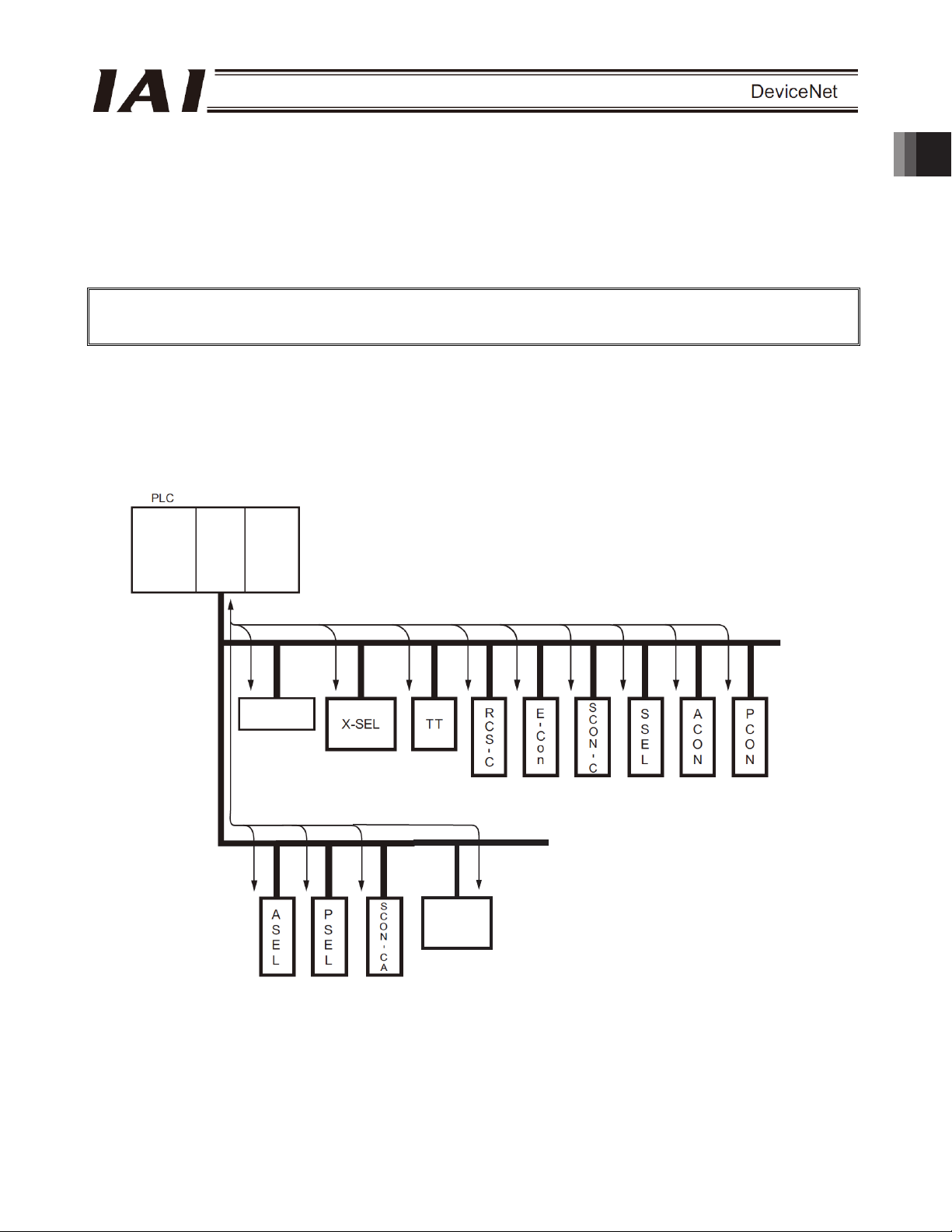
The open field network DeviceNet is a multi-bit, multi-vendor network for communication of both control and data
signals of the machine/line control level.
A wire-saving system can be built by connecting IAI’s X-SEL, TT, RCS-C, E-Con, ASEL, PSEL, SSEL, SCON,
ACON and PCON controllers (hereinafter collectively and individually referred to as “Each Controller”) to a
DeviceNet network.
Each controller is treated as a slave station in DeviceNet and can be used to exchange I/O data.
This Operation Manual covers the ACON, PCON, PCON-CA/CFA and SCON-CA series.
* For details on DeviceNet, refer to the operation manual for the programmable controller (hereinafter referred to
as “PLC”) in which the master unit is installed.
This operation manual should be used in conjunction with the operation manual for each controller.
You should also assume that any usage not specifically permitted in this operation manual is prohibited.
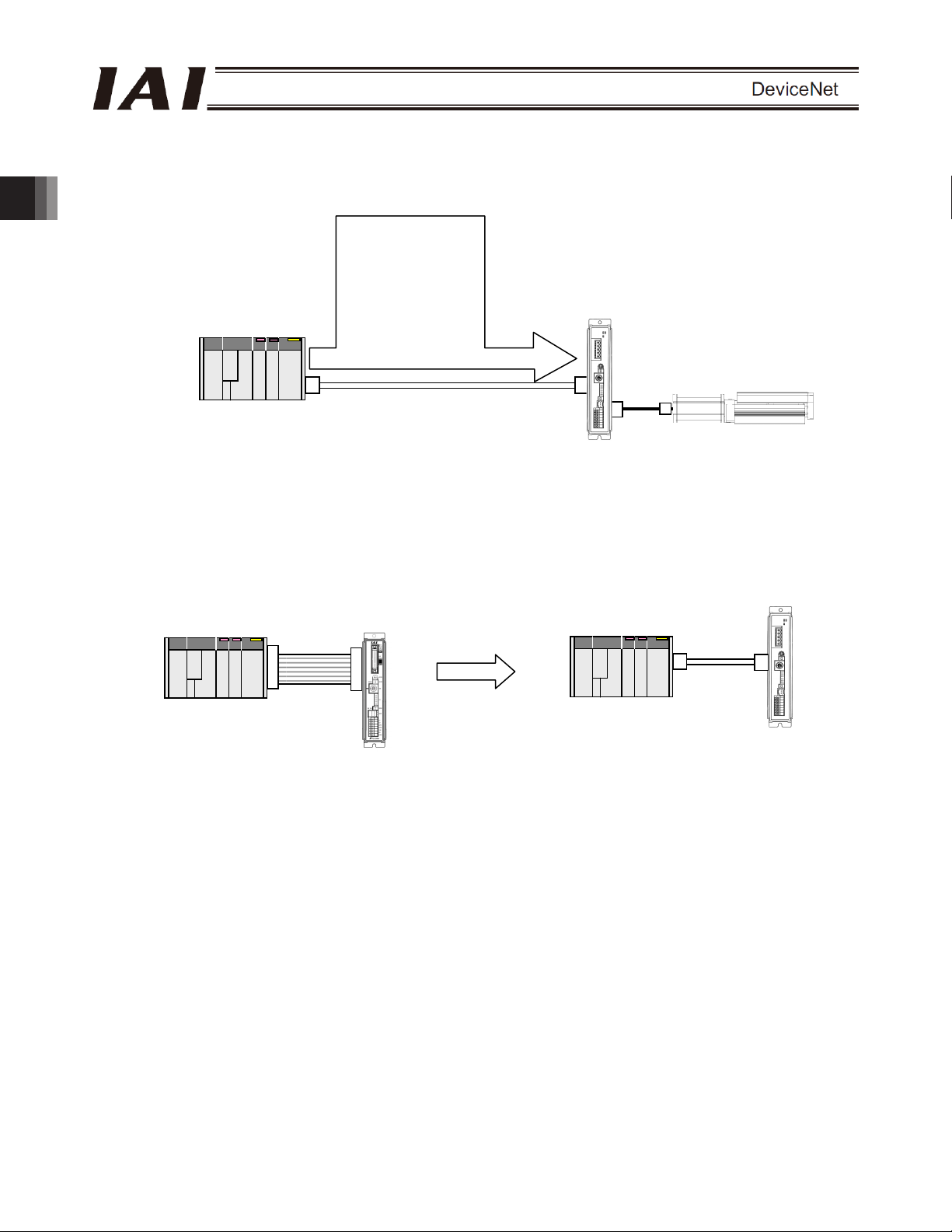
System configuration example
1. Overview
/8
/8
97
/8 /8
/
'+'
/8
/8 /8 /8
/8 /8 /8
/8 /8 /8
9
Page 16
A
A
2. ACON-C/CG, PCON-C/CG
2.1 Operation Modes and Functions
ACON and PCON controllers supporting DeviceNet can be operated in a desired operation mode selected from
the following five modes.
Operation Modes and Key Functions
Number of occupied
Operation by position
data specification
2. ACON-C/CG, PCON-C/CG
Direct
speed/acceleration
specification
Push-motion
operation
Current position read x
Current speed read x x
Operation by position
number specification
Completed position
number read
Maximum position
table size
(*1) The actuator is operated by specifying all position data, other than positions, using position numbers.
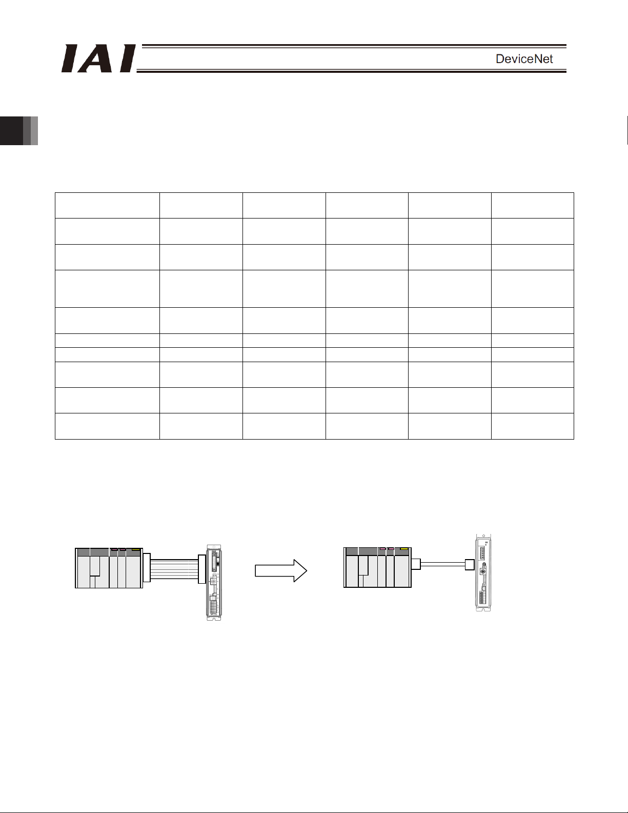
[1] Remote I/O mode: In this mode, the actuator is operated by PIOs (24-V I/Os) via DeviceNet communication.
Key function
bytes
PLC
PIO connection
Remote I/O
mode
Position/simple
direct mode
1CH 4CH 8CH 16CH CH
x { (*1)
x x
{ { { { {
{ { { {
{ {
{ {
512 768 Not used Not used 512
Number of occupied bytes: 1CH
CON/PCON not
supporting
Flat cable
DeviceNet
Half direct mode Full direct mode
{ {
{ {
{ {
x x
x x
CON/PCON supporting
DeviceNet
PLC
Communication
cable
DeviceNet connection
Remote I/O
mode 2
x
x
x
{
{
10
Page 17
A
A
r
A
A
A
A
r
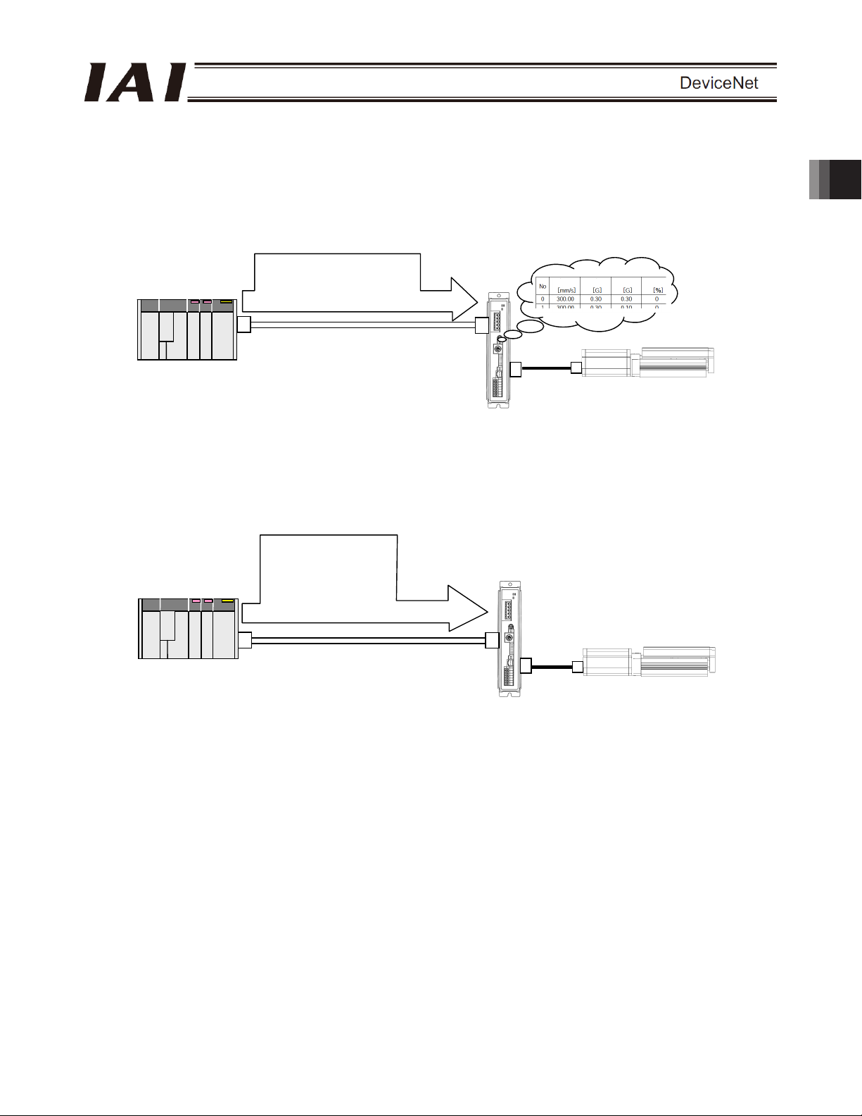
[2] Position/simple direct mode: In this mode, the actuator is operated by specifying position numbers.
You can select whether to specify the target position directly as a value, or use
a value registered in the position data table, by switching a control signal.
For the speed, acceleration/deceleration, positioning band, etc., values
preregistered in the position data table are used. Up to 768 position data points
can be set.
Number of occupied bytes: 4CH
PLC
䎃
Target position: 100.00 mm
+
Position No. 0
Speed
cceleration
Deceleration
Push
CON/PCON supporting
DeviceNet
ctuato
[3] Half direct mode: In this mode, the actuator is operated by specifying the speed, acceleration/deceleration
and push current, in addition to the target position, directly as values.
Number of occupied bytes: 8CH
PLC
䎃
Target position: 100.00 mm
Positioning band: 0.10 mm
Speed specification: 100.0
mm/sec
cceleration/deceleration:
0.30 G
Push current: 50%
CON/PCON supporting
DeviceNet
ctuato
2. ACON-C/CG, PCON-C/CG
11
Page 18
A
A
A
r
A
A
[4] Full direct mode: In this mode, the actuator is operated by specifying all values relating to position control
2. ACON-C/CG, PCON-C/CG
[5] Remote I/O mode 2: In this mode, the actuator is operated by PIOs (24-V I/Os) via DeviceNet
PLC
(target position, speed, acceleration/deceleration, etc.) directly as values.
Number of occupied bytes: 16CH
Target position: 100.00 mm
Positioning band: 0.10 mm
Speed specification:
100.0 mm/sec
cceleration: 0.30 G
Deceleration: 0.30 G
Push current: 50%
䎳䎯䎦䎃
Load current threshold: 0
Zone+: 50.00 mm
Zone-: 30.00 mm
CON/PCON supporting
DeviceNet
communication.
The current-position and command-current read functions are available in addition to
the functions provided in mode [1].
Number of occupied bytes: 6CH
CON/PCON not
supporting DeviceNet
Flat cable
PIO connection
PLC
DeviceNet connection
ctuato
CON/PCON supporting
DeviceNet
Communication
cable
12
Page 19
2.2 Model Numbers
The model numbers of ACON and PCON controller supporting DeviceNet are indicated as follows, respectively:
z ACON-C/CG--DV-
z PCON-C/CG--DV-
Printed series name
z ACON
z PCON
Front panel color
z ACON: Dark blue
z PCON: Dark green
2. ACON-C/CG, PCON-C/CG
13
Page 20

2.3 Interface Specifications
Communication protocol
Baud rate Automatically set to the same value as the band rate set in the master
Communication cable length
2. ACON-C/CG, PCON-C/CG
Communication power supply 24 VDC (supplied from DeviceNet)
Consumption current of
communication power supply
Number of occupied nodes 1 node
Connector MSTBA2.5/5-G-5.08AU M (*1) by Phoenix Contact
(*1) The cable-end connector is a standard accessory.
Item Specification
DeviceNet 2.0
Group 2 only server
Network-powered isolation node
Baud rate Maximum network length Maximum branch
500 kbps 100 m 39 m
250 kbps 250 m 78 m
125 kbps 500 m
Note) When a large-size DeviceNet cable is used.
60 mA
SMSTB2.5/5-ST-5.08AU by Phoenix Contact
Bit strobe Communication specification Master-slave connection
Polling
line length
6 m
Total branch
line length
156 m
14
Page 21

2.4 DeviceNet Interface
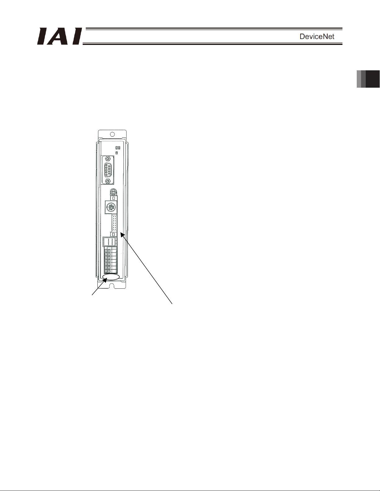
2.4.1 Name of Each Part
The name of each part relating to DeviceNet is shown.
Status LEDs
Monitor LEDs
Red
White
Light blue
Black
DeviceNet communication connector
PCB side : MSTBA2.5/5-G-5.08AUM
Cable side : SMSTB2.5/5-ST-5.08AU
2. ACON-C/CG, PCON-C/CG
(PHOENIX CONTACT)
(PHOENIX CONTACT)
15
Page 22

2.4.2 Monitor LED Indicators
The two LEDs, MS and NS, provided on the front panel of the controller are used to check the node (controller)
condition and network condition.
The LEDs illuminate in two colors (orange and green), and you can monitor the conditions listed in the table below
based on the illumination status and color of each LED.
MS (Module Status) LED: Condition of the node (controller)
NS (Network Status) LED: Condition of the network
LED Color
2. ACON-C/CG, PCON-C/CG
{ : Steady light, X : Off, ڏ : Blinking
Illumination
status
{
Green
MS
Orange
- X DeviceNet is initializing or the power is not supplied.
Green
NS
Orange
- X
Self test is performed when the power is turned on.
During the test, the monitor LEDs cycle in the following sequence:
[1] NS turns off.
[2] MS illuminates in steady green (approx. 0.25 second).
[3] MS illuminates in steady orange (approx. 0.25 second).
[4] MS illuminates in steady green.
[5] NS illuminates in steady green (approx. 0.25 second).
[6] NS illuminates in steady orange (approx. 0.25 second).
[7] NS turns off.
When the self test is finished and the board starts communicating normally, both the MS and NS LEDs
change to steady green.
ڏ
{
ڏ
{
ڏ
{
ڏ
The board is operating normally.
A hardware error occurred. The error may be reset by
reconnecting the power.
A hardware error occurred. The board must be replaced.
A user setting error, configuration error or other minor error is
present. These errors can be reset by setting the applicable item
again, etc.
Network connection has been established and the board is
communicating normally.
The board is online, but network connection is not yet established.
Communication is stopped. (The network is normal.)
Node address duplication or bus-off state was detected.
Communication is not possible.
A communication error occurred (communication time-out
occurred).
The board is not online.
DeviceNet power is not supplied.
Description (meaning)
16
Page 23

2.5 Selecting (Setting) the Operation Mode
The operation mode is set using a parameter.
Set the mode selector switch on the front panel of the controller to the MANU position, and set parameter No. 84,
“FMOD: Fieldbus operation mode” using the RC PC software (V6.00.05.00 or later). (Refer to 2.10, “DeviceNet
Parameters.”)
Set value Operation mode
0 (Factory setting) Remote I/O mode 1CH
1 Position/simple direct mode 4CH
2 Half direct mode 8CH
3 Full direct mode 16CH
4 Remote I/O mode 2 6CH
* If any other value is entered, an excessive input error will occur.
Number of occupied
stations
2.6 Setting the Node Address
The node address is set using a parameter.
Set parameter No. 85, “NADR: Fieldbus node address” using the RC PC software. (Refer to 2.10, “DeviceNet
Parameters.”)
Allowable setting range: 0 to 63 (The parameter has been set to “63” at the factory.)
(Note) Exercise caution to avoid node address duplication.
The nodes (controllers) are assigned in the order of their node address in the remote I/O address areas of
the PLC. (This is when the mount assignment mode is selected. A different rule applies when a
configurator is used.)
For details, refer to the operation manuals of the master unit and PLC installed in the master unit.
(Note) The baud rate is automatically set to the same value as the baud rate set in the master. Accordingly, you
need not set the baud rate.
(Note) After you have set the parameter, reconnect the controller power and return the mode selector switch on
the front panel of the controller to the AUTO position. If the switch remains in the MANU position,
operation by the PLC cannot be performed.
2. ACON-C/CG, PCON-C/CG
17
Page 24
2.7 Communicating with the Master Station
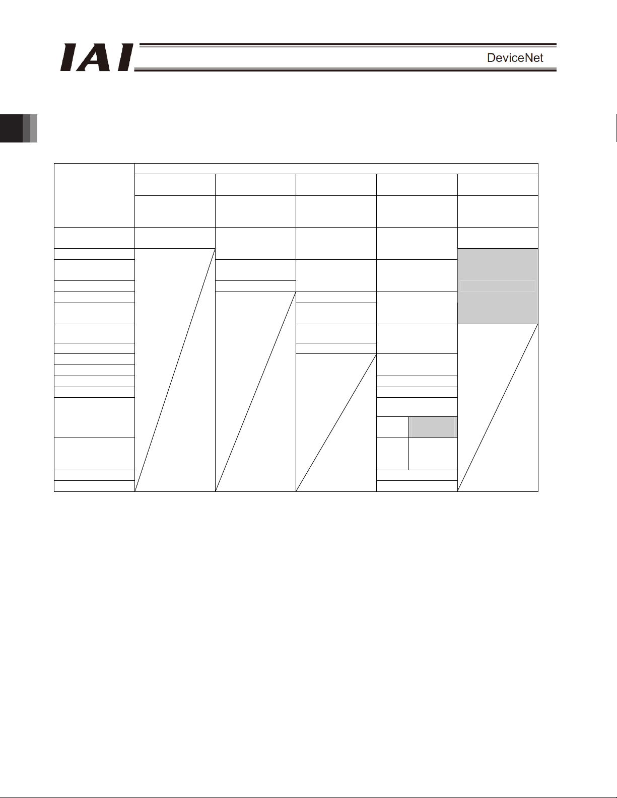
2.7.1 Operation Modes and Corresponding PLC I/O Areas
The channel assignments in each mode are shown below.
x PLC output o ACON or PCON input (* n indicates the node address of each axis.)
PLC output area
2. ACON-C/CG, PCON-C/CG
(Note) The areas denoted by “occupied area” are occupied according to the operation mode setting.
ACON,PCON DI and input data register
Remote I/O mode
(channel)
n
n+1
n+2
n+3 Control signal
n+4 Speed
n+5
n+6
n+7 Control signal
n+8
n+9
n+10 Acceleration
n+11 Deceleration
n+12
ACON
n+13 PCON
n+14 Control signal 1
n+15
Number of
occupied
channels: 1CH
Port number 0 to
15
Position/simple
direct mode
Number of
occupied
channels: 4CH
Target position Target position Target position
Specified position
number
Half direct mode Full direct mode
Number of
occupied
channels: 8CH
Positioning band Positioning band
Acceleration/
deceleration
Push-motion
current-limiting value
Number of
occupied
channels: 16CH
Speed
specification
Zone boundary+
Zone boundary-
Push-motion
current-limiting value
Occupied
area
Load
current
threshold
Control signal 2
Remote I/O mode
2
Number of
occupied
channels: 6CH
Port number 0 to
15
Occupied area
These areas cannot be used for any other purpose. Also exercise caution to avoid node address
duplication.
18
Page 25

x ACON or PCON output o PLC input side (* n indicates the node address of each axis.)
ACON or PCON DO and output data register
PLC input area
(channel)
n
n+1
n+2
n+3
n+4 Status signal
n+5
n+6
n+7 Alarm code Alarm code
n+8 Status signal
n+9
n+10
n+11
n+12
n+13
n+14
n+15
Remote I/O mode
Number of
occupied
channels: 1CH
Port number 0 to
15
Position/simple
direct mode
Number of
occupied
channels: 4CH
Current position Current position Current position
Completed
position number
(simple alarm ID)
Half direct mode Full direct mode
Number of
occupied
channels: 8CH
Command current Command current Current position
Current speed Current speed Command current
Number of
occupied
channels: 16CH
Occupied area
Status signal
Remote I/O mode
2
Number of
occupied
channels: 6CH
Port number 0 to
15
Occupied area
(Note) The areas denoted by “occupied area” are occupied according to the operation mode setting.
These areas cannot be used for any other purpose. Also exercise caution to avoid node address
duplication.
2. ACON-C/CG, PCON-C/CG
19
Page 26

2.7.2 Remote I/O Mode (Number of Occupied Channel: 1)
In this mode, the actuator is operated by specifying position numbers, just like you do when PIOs (24-V I/Os) are
used.
Set position data using the RC PC software or teaching pendant.
The number of available positions is determined by the setting of parameter No. 25, “PIO pattern.”
The I/O specifications for each PIO pattern are shown below. (For details, refer to the operation manual for the
controller.)
parameter No. 25
2. ACON-C/CG, PCON-C/CG
The key ROBO Cylinder functions that can be controlled in this mode are summarized in the table below.
Home-return operation
Positioning operation
Speed and
acceleration/deceleration setting
Pitch feed (inching)
Push-motion operation
Speed change during movement
Operation at different
acceleration and deceleration
Pause
Zone signal output
PIO pattern selection (set by a
parameter)
(*1) This function is supported when parameter No. 27, “Move command type” is set to “0.”
Value set in
0 Positioning mode 64 positioning points and two zone output points are available.
1 Teaching mode 64 positioning points and one zone output point is available.
2 256-point mode 256 positioning points and one zone output point is available.
3 512-point mode 512 positioning points are available. There are no zone outputs.
4 Solenoid mode 1 7 positioning points and two zone output points are available.
5 Solenoid mode 2 3 positioning points and two zone output points are available.
ROBO Cylinder function
The actuator can be paused by turning the move command OFF.
Operation mode I/O specification
Positioning operation and jog operation are supported.
The current position can be written to a specified position.
A direct operation command can be issued for each position
number.
A position complete signal is output for each position number.
The actuator is operated by specifying forward, backward and
intermediate position commands.
A position complete signal is output separately for the front end,
rear end and intermediate position.
{: Supported / X: Not supported
PIO patterns
0:
Positioning
mode
{ { { { {
{ { { { { {
{ { { { { {
{ { { { { {
{ { { { {
{ { { { { {
{ { { { { {
{ { { { {
{ { {
{ { { { { {
1:
Teaching
mode
2:
256-point
mode
3:
512-point
mode
X
4:
Solenoid
mode 1
{ {
5:
Solenoid
mode 2
X
X
{ (*1)
20
Page 27
(1) PLC channel configuration (* n indicates the node address of each axis.)
Parameter No.
84
ACON or PCON DI
(port number)
PLC output channel
ACON or PCON DO
(port number)
PLC input channel
0 0~15 n+0 0~15 n+0
(Note) Exercise caution to avoid node address duplication.
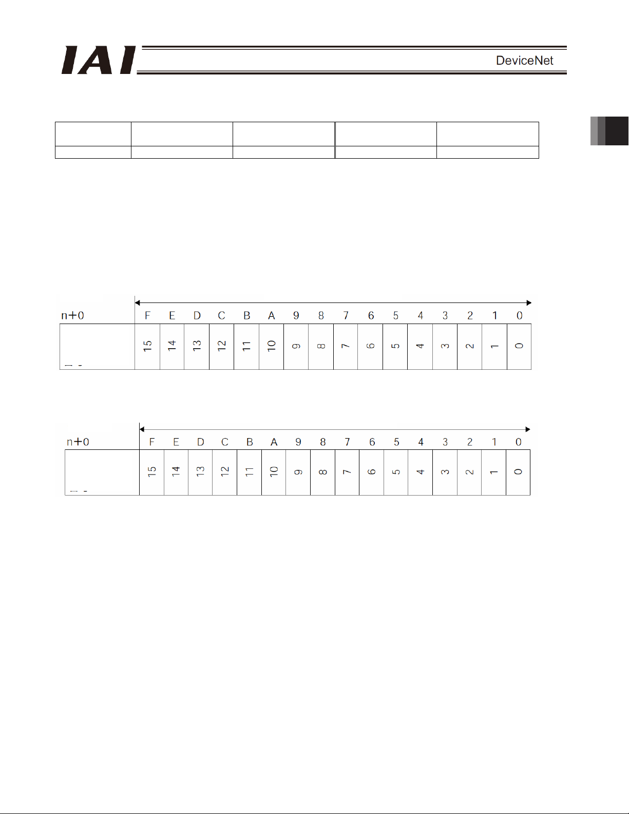
(2) I/O signal assignments for each axis
The I/O signals of each axis consist of one input word (channel) and one output word (channel) in the I/O areas.
z Each channel is controlled by ON/OFF bit signals.
PLC output
Channel (* n indicates the node address of each axis.)
Controller
input port
number
PLC input
Channel (* n indicates the node address of each axis.)
Controller
output port
number
1 word (channel) = 16 bits
1 word (channel) = 16 bits
2. ACON-C/CG, PCON-C/CG
21
Page 28

(3) I/O signal assignments
The signals assigned to the controller’s I/O ports vary depending on the setting of parameter No. 25.
(For details, refer to the operation manual for the controller.)
ACON
Category
2. ACON-C/CG, PCON-C/CG
PLC
output o
ACON
input
ACON
output o
PLC input
The signals indicated by * are ON in a normal state.
The signals denoted by “Not available” are not controlled (their ON/OFF status is indeterminable).
Setting of Parameter No. 25
Port
No.
0 PC1 PC1 PC1
1 PC2 PC2 PC2
2 PC4 PC4 PC4
3 PC8 PC8 PC8
4 PC16 PC16 PC16
5 PC32
6 - MODE
7 - JISL Jog/inch switching PC128
8 9 BKRL
10 RMOD Operation mode RMOD Operation mode RMOD Operation mode
11 HOME Home return HOME Home return HOME Home return
12 *STP Pause *STP Pause *STP Pause
13 CSTR Positioning start
14 RES Reset RES Reset RES Reset
15 SON Servo ON command SON Servo ON command SON Servo ON command
0 PM1 PM1 PM1
1 PM2 PM2 PM2
2 PM4 PM4 PM4
3 PM8 PM8 PM8
4 PM16 PM16 PM16
5 PM32
6 MOVE Moving signal MOVE Moving signal PM64
7 ZONE1 Zone 1 MODES
8 PZONE Position zone PZONE Position zone PZONE Position zone
9 RMDS
10 HEND
11 PEND
12 SV Ready SV Ready SV Ready
13 *EMGS Emergency stop *EMGS Emergency stop *EMGS Emergency stop
14 *ALM Alarm *ALM Alarm *ALM Alarm
15 - Not available. - Not available. - Not available.
Positioning mode Teaching mode 256-point mode
0 1 2
Symbol Signal name Symbol Signal name Symbol Signal name
Command position
number
Not available.
Forced brake
release
Completed position
number
Operation mode
status
Home return
complete
Position complete
signal
PC32
JOG+ +Jog - Not available.
JOG- -Jog BKRL
CSTR/
PWRT
PM32
RMDS
HEND
PEND/
WEND
Command position
number
Teaching mode
command
Positioning
start/position-data
read command
Completed position
number
Teaching mode
signal
Operation mode
status
Home return
complete
Position complete
signal/position-data
read complete
Command position
PC32
PC64
CSTR Positioning start
PM32
PM128
RMDS
HEND
PEND
number
Forced brake
release
Completed position
number
Operation mode
status
Home return
complete
Position complete
signal
22
Page 29

ACON
Setting of Parameter No. 25
Category
PLC
output o
ACON
input
ACON
output o
PLC input
Port
No.
0 PC1 ST0 Start position 0 ST0 Start position 0
1 PC2 ST1 Start position 1 ST1 Start position 1
2 PC4 ST2 Start position 2 ST2 Start position 2
3 PC8 ST3 Start position 3 4 PC16 ST4 Start position 4 5 PC32 ST5 Start position 5 6 PC64 ST6 Start position 6 7 PC128 - 8 PC256
9 BKRL
10 RMOD Operation mode RMOD Operation mode RMOD Operation mode
11 HOME Home return HOME Home return 12 *STP Pause *STP Pause 13 CSTR Positioning start - Not available. 14 RES Reset RES Reset RES Reset
15 SON Servo ON command SON Servo ON command SON Servo ON command
0 PM1 PE0 Position 0 complete LS0
1 PM2 PE1 Position 1 complete LS1
2 PM4 PE2 Position 2 complete LS2
3 PM8 PE3 Position 3 complete -
4 PM16 PE4 Position 4 complete 5 PM32 PE5 Position 5 complete 6 PM64 PE6 Position 6 complete 7 PM128 ZONE1 Zone 1 ZONE1 Zone 1
8 PM256
9 RMDS
10 HEND
11 PEND
12 SV Ready SV Ready SV Ready
13 *EMGS Emergency stop *EMGS Emergency stop *EMGS Emergency stop
14 *ALM Alarm *ALM Alarm *ALM Alarm
15 - Not available. - Not available. - Not available.
512-point mode Solenoid mode 1 Solenoid mode 2
3 4 5
Symbol Signal name Symbol Signal name Symbol Signal name
Command position
number
Not available.
Not available.
Forced brake
release
Operation mode
status
Home return
complete
Position complete
signal
-
BKRL
RMDS
HEND
-
Forced brake
release
Not available.
Rear end move
command 0
Rear end move
command 1
Rear end move
command 2
Not available.
Operation mode
status
Home return
complete
Position complete
signal
Forced brake
release
Completed position
number
Operation mode
status
Home return
complete
Position complete
signal
-
BKRT
PZONE Position zone PZONE Position zone
RMDS
HEND
PEND
The signals indicated by * are ON in a normal state.
The signals denoted by “Not available” are not controlled (their ON/OFF status is indeterminable).
2. ACON-C/CG, PCON-C/CG
23
Page 30

PCON
Category
2. ACON-C/CG, PCON-C/CG
PLC
output o
PCON
input
PCON
output o
PLC input
The signals indicated by * are ON in a normal state.
The signals denoted by “Not available” are not controlled (their ON/OFF status is indeterminable).
Setting of Parameter No. 25
Port
No.
0 PC1 PC1 PC1
1 PC2 PC2 PC2
2 PC4 PC4 PC4
3 PC8 PC8 PC8
4 PC16 PC16 PC16
5 PC32
6 - MODE
7 - JISL Jog/inch switching PC128
8 -
9 BKRL
10 RMOD Operation mode RMOD Operation mode RMOD Operation mode
11 HOME Home return HOME Home return HOME Home return
12 *STP Pause *STP Pause *STP Pause
13 CSTR Positioning start
14 RES Reset RES Reset RES Reset
15 SON Servo ON command SON Servo ON command SON Servo ON command
0 PM1 PM1 PM1
1 PM2 PM2 PM2
2 PM4 PM4 PM4
3 PM8 PM8 PM8
4 PM16 PM16 PM16
5 PM32
6 MOVE Moving signal MOVE Moving signal PM64
7 ZONE1 Zone 1 MODES
8 PZONE Position zone PZONE Position zone PZONE Position zone
9 RMDS
10 HEND
11 PEND
12 SV Ready SV Ready SV Ready
13 *EMGS Emergency stop *EMGS Emergency stop *EMGS Emergency stop
14 *ALM Alarm *ALM Alarm *ALM Alarm
15
Positioning mode (standard)
0 1 2
Symbol Signal name Symbol Signal name Symbol Signal name
Command position
number
Not available.
Forced brake
release
Completed position
number
Operation mode
status
Home return
complete
Position complete
signal
LOAD/
TRQS
Load output
judgment/torque
level
Teaching mode
(teaching type)
Command position
number
PC32
Teaching mode
command (operation
mode)
JOG+ +Jog - Not available.
JOG- -Jog BKRL
CSTR/
PWRT
PM32
RMDS
HEND
PEND/
WEND
- Not available.
Positioning
start/position-data
read command
Completed position
number
Teaching mode
signal
Operation mode
status
Home return
complete
Position complete
signal/position-data
read complete
256-point mode
(256-point type)
Command position
PC32
PC64
CSTR Positioning start
PM32
PM128
RMDS
HEND
PEND
LOAD/
TRQS
number
Forced brake
release
Completed position
number
Operation mode
status
Home return
complete
Position complete
signal
Load output
judgment/torque
level
24
Page 31

PCON
Setting of Parameter No. 25
Category
PLC
output o
PCON
input
PCON
output o
PLC input
Port
No.
0 PC1 ST0 Start position 0 ST0 Start position 0
1 PC2 ST1 Start position 1 ST1 Start position 1
2 PC4 ST2 Start position 2 ST2 Start position 2
3 PC8 ST3 Start position 3 4 PC16 ST4 Start position 4 5 PC32 ST5 Start position 5 6 PC64 ST6 Start position 6 7 PC128 - 8 PC256
9 BKRL
10 RMOD Operation mode RMOD Operation mode RMOD Operation mode
11 HOME Home return HOME Home return 12 *STP Pause *STP Pause 13 CSTR Positioning start - Not available. 14 RES Reset RES Reset RES Reset
15 SON Servo ON command SON Servo ON command SON Servo ON command
0 PM1 PE0 Position 0 complete LS0
1 PM2 PE1 Position 1 complete LS1
2 PM4 PE2 Position 2 complete LS2
3 PM8 PE3 Position 3 complete -
4 PM16 PE4 Position 4 complete 5 PM32 PE5 Position 5 complete 6 PM64 PE6 Position 6 complete 7 PM128 ZONE1 Zone 1 ZONE1 Zone 1
8 PM256
9 RMDS
10 HEND
11 PEND
12 SV Ready SV Ready SV Ready
13 *EMGS Emergency stop *EMGS Emergency stop *EMGS Emergency stop
14 *ALM Alarm *ALM Alarm *ALM Alarm
15
512-point mode Solenoid mode 1 Solenoid mode 2
3 4 5
Symbol Signal name Symbol Signal name Symbol Signal name
Command position
number
Not available.
Not available.
Forced brake
release
Operation mode
status
Home return
complete
Position complete
signal
Load output
judgment/torque
level
-
BKRL
RMDS
HEND
-
- Not available.
Forced brake
release
Not available.
Rear end move
command 0
Rear end move
command 1
Rear end move
command 2
Not available.
Operation mode
status
Home return
complete
Position complete
signal
LOAD/
TRQS
Forced brake
release
Completed position
number
Operation mode
status
Home return
complete
Position complete
signal
Load output
judgment/torque
level
-
BKRT
PZONE Position zone PZONE Position zone
RMDS
HEND
PEND
LOAD/
TRQS
The signals indicated by * are ON in a normal state.
The signals denoted by “Not available” are not controlled (their ON/OFF status is indeterminable).
2. ACON-C/CG, PCON-C/CG
25
Page 32

2.7.3 Position/Simple Direct Mode (Number of Occupied Channels: 4)
In this mode, the actuator is operated by specifying position numbers. You can switch the control signal (PMOD)
to select whether to specify the target position directly and numerically or by using a value registered in the
position data table.
Data other than the target position, such as speed, acceleration/deceleration and positioning band, are set using
values in the position table stored in the controller. Set position data by referring to the operation manual for the
controller.
Up to 768 sets of positioning data can be specified.
The key ROBO Cylinder functions that can be controlled in this mode are summarized in the table below.
Home-return operation
Positioning operation
2. ACON-C/CG, PCON-C/CG
Speed and acceleration/deceleration setting U
Pitch feed (inching) U
Push-motion operation U
Speed change during movement U
Operation at different acceleration and deceleration U
Pause
Zone signal output
PIO pattern selection X
(1) PLC channel configuration (* n indicates the node address of each axis.)
ROBO Cylinder function
{: Direct control
U: Indirect control
X: Invalid
{
{
{
U Zones are set using
Remarks
These items must be
set in the position data
table.
parameters.
Parameter No.
84
1
(Note) Exercise caution to avoid node address duplication.
ACON or PCON
input register
Target position
Specified position
number
Control signal n+3 Status signal n+3
PLC output channel
n+0 n+0
n+1
n+2
ACON or PCON
output register
Current position
Completed position
number (simple
alarm code)
PLC input channel
n+1
n+2
26
Page 33

(2) I/O signal assignments for each axis
The I/O signals of each axis consist of four input words (channels) and four output words (channels) in the I/O
areas.
z Control signals and status signals are ON/OFF bit signals.
z The target position and current position are 2-word (32-bit) binary data. Although values from -999999 to
+999999 (unit: 0.01 mm) can be handled by the PLC for these items, set position data within the soft stroke
range (0 to the effective stroke) of the applicable actuator.
z The specified position number and completed position number are 1-word (16-bit) binary data. Although
values from 0 to 767 can be handled by the PLC for these items, use the PC software or teaching pendant to
specify position numbers associated with predefined operating conditions
PLC output
Channel (* n indicates the node address of each axis.)
Target position
(lower word)
Target position
(upper word)
Specified
position
number
Control signal
If the target position is a negative value, it is indicated by a 2’s complement.
1 word (channel) = 16 bits
.
2. ACON-C/CG, PCON-C/CG
27
Page 34

PLC input
Channel (* n indicates the node address of each axis.)
Current
position (lower
word)
Current
position
(upper word)
2. ACON-C/CG, PCON-C/CG
Completed
position
number
Status signal
1 word (channel) = 16 bits
If the current position is a negative value, it is indicated by a 2’s complement.
28
Page 35

(3) I/O signal assignments
(* In the table, ON indicates that the applicable bit is “1,” while OFF indicates that the bit is “0.”)
Signal type Bits Symbol Description Details
32-bit signed integer.
Specify the target position as a position in the absolute
coordinate system.
The setting unit is 0.01 mm and the allowable specification range
Target
position
Specified
position
number
PLC output
Control
signal
32-bit data -
16-bit data
b15 BKRL
b14 RMOD
b13
b12
b11 PMOD
b10 MODE
b9 PWRT
b8 JOG+
b7 JOG-
b6 JVEL
b5 JISL
b4 SON
b3 RES Reset: A reset is performed when this signal turns ON. 2.7.7 (4)
b2 STP Pause: A pause command is issued when this signal turns ON. 2.7.7 (11)
b1 HOME
b0 CSTR
PC1 ~
PC512
is -999999 to 999999.
(Example) To set “+25.40 mm,” specify “2540.”
If the entered value exceeds the range between the soft limits
(0.2 mm inside the limits) set by the parameters, the movement
will be limited to the soft limit (0.2 mm inside the limit).
* If target positions are entered as hexadecimals, enter negative
values using 2’s complements.
16-bit integer.
To operate the actuator, you must set position data associated
with predefined operating conditions using the PC software or
teaching pendant.
Use one of these registers to specify the position number for
which the desired data has been input.
The allowable specification range is 0 to 767.
If the specified value is outside the above range or corresponds
to a position not yet set, an alarm will occur when the start signal
is turned ON.
Forced brake release: The brake is released when this signal
turns ON.
Operation mode: The AUTO mode is selected when this signal is
OFF, and the MANU mode is selected when the signal is ON.
- Not available. -
Position/simple-direct switching: The position mode is selected
when this signal is OFF, and the simple direct mode is selected
when the signal is ON.
Teaching mode command: The normal mode is selected when
this signal is OFF, and the teaching mode is selected when the
signal is ON.
Position-data read command: Position data is read when this
signal is ON.
+Jog: The actuator moves in the direction opposite home when
this signal is ON.
-Jog: The actuator moves in the direction of home when this
signal is ON.
Jog-speed/inch-distance switching: The values set in parameter
No. 26, “Jog speed” and parameter No. 48, “Inch distance” are
used when this signal is OFF, and the values set in parameter
No. 47, “Jog speed 2” and parameter No. 49, “Inch distance 2”
are used when the signal is ON.
Jog/inch switching: Jog operation is performed when this signal
is OFF, and inch operation is performed when the signal is ON.
Servo ON command: The servo turns ON when this signal turns
ON.
Home return: A home-return command is issued when this signal
turns ON.
Positioning start: A move command is issued when this signal
turns ON.
2.9 (1)
2.9 (1)
2.7.7 (18)
2.7.7 (19)
2.7.7 (20)
2.7.7 (16)
2.7.7 (17)
2.7.7 (13)
2.7.7 (13)
2.7.7 (14)
2.7.7 (15)
2.7.7 (5)
2.7.7 (6)
2.7.7 (7)
2. ACON-C/CG, PCON-C/CG
29
Page 36

(* In the table, ON indicates that the applicable bit is “1,” while OFF indicates that the bit is “0.”)
Signal type Bits Symbol Description Details
2. ACON-C/CG, PCON-C/CG
PLC input
Current
position
Completed
position
number
(simple
alarm
code)
Status
signal
32-bit signed integer indicating the current position.
The setting unit is 0.01 mm.
32 bits -
16 bits
b15 EMGS
b14 PWR
b13 ZONE2
b12 ZONE1
b11 PZONE
b10 MODES
b9 WEND
b8 RMDS
b7
b6
b5 PSFL
b4 SV Ready: This signal turns ON when the servo turns ON. 2.7.7 (5)
b3 ALM Alarm: This signal turns ON when an alarm occurs. 2.7.7 (3)
b2 MOVE
b1 HEND
b0 PEND
PM 1 ~
PM512
(Example) Reading: 000003FFH = 1023 (decimal)
= 10.23 mm
* If current positions are read as hexadecimals, negative values
are indicated by 2’s complements.
16-bit integer.
When the actuator has moved to the target position and entered
the positioning band, the position number corresponding to the
completed position is output.
“0” is output when no position movement has been performed
yet or while the actuator is moving.
If an alarm occurs (the status signal ALM turns ON), a
corresponding simple alarm code (refer to the operation manual
for the controller) will be output.
Emergency stop: An emergency stop is actuated when this
signal turns ON.
Controller ready: This signal turns ON when the controller
becomes ready.
Zone 2: This signal turns ON when the current position is inside
the specified zone.
Zone 1: This signal turns ON when the current position is inside
the specified zone.
Position zone: This signal turns ON when the current position is
inside the specified position zone.
Teaching mode signal: This signal is ON while the teaching
mode is selected.
Position data read complete: This signal turns ON when reading
is complete.
Operation mode status: This signal is OFF when the current
mode is AUTO, or ON when the current mode is MANU.
- Not available. -
Load missed in push motion: This signal turns ON when the
actuator missed the load in push-motion operation.
Moving signal: This signal remains ON while the actuator is
moving.
Home return complete: This signal turns ON when home return
is completed.
Position complete signal: This signal turns ON when positioning
is completed.
2.9 (1)
2.9 (1)
2.7.7 (2)
2.7.7 (1)
2.7.7 (12)
2.7.7 (12)
2.7.7 (12)
2.7.7 (16)
2.7.7 (17)
2.7.7 (19)
2.7.7 (23)
2.7.7 (9)
2.7.7 (6)
2.7.7 (10)
30
Page 37

2.7.4 Half Direct Mode (Number of Occupied Channels: 8)
In this mode, the target position, positioning band, speed, acceleration/deceleration and push-motion current are
specified directly and numerically from the PLC.
Set each value in the I/O areas. To use the zone function, set appropriate values in parameter Nos. 1, 2, 23 and
24.
The key ROBO Cylinder functions that can be controlled in this mode are summarized in the table below.
{: Direct control
ROBO Cylinder function
Home-return operation
Positioning operation
Speed and acceleration/deceleration setting
Pitch feed (inching)
Push-motion operation
Speed change during movement
Operation at different acceleration and deceleration X
Pause
Zone signal output
PIO pattern selection X
U: Indirect control
X: Invalid
{
{
{
{
{
{
{
U Parameters must be
Remarks
set
(1) PLC channel configuration (* n indicates the node address of each axis.)
2. ACON-C/CG, PCON-C/CG
Parameter No.
84
2
(Note) Exercise caution to avoid node address duplication.
ACON or PCON
input register
Target position
Positioning band
Speed n+4 n+4
Acceleration/
deceleration
Push-motion
current-limiting value
Control signal n+7 Status signal n+7
PLC output channel
n+0 n+0
n+1
n+2 n+2
n+3
n+5
n+6 Alarm code n+6
ACON or PCON
output register
Current position
Command current
Current speed
PLC input channel
n+1
n+3
n+5
31
Page 38

g
(2) I/O signal assignments for each axis
The I/O signals of each axis consist of eight input words (channels) and eight output words (channels) in the I/O
areas.
z Control signals and status signals are ON/OFF bit signals.
z The target position and current position are 2-word (32-bit) binary data. Although values from -999999 to
z Specify the positioning band. The positioning band is a 2-word (32-bit) binary data. For the positioning band,
z The speed is a 1-word (16-bit) binary data. For the specified speed, the PLC can handle values from 0 to
z The acceleration/deceleration is a 1-word (16-bit) binary data. For the acceleration/deceleration, the PLC can
2. ACON-C/CG, PCON-C/CG
z The push-motion current-limiting value is a 1-word (16-bit) binary data. For the push-motion current-limiting
z The command current is a 2-word (32-bit) binary data (unit: 1 mA).
z The current speed is a 2-word (32-bit) binary data (unit: 0.01 mm/sec).
z The alarm code is a 1-word (16-bit) binary data.
+999999 (unit: 0.01 mm) can be handled by the PLC for these items, set position data within the soft stroke
range (0 to the effective stroke) of the applicable actuator.
the PLC can handle values from 1 to +999999 (unit: 0.01 mm).
+65535 (unit: 1.0 mm/sec). Take note, however, that the set value should not exceed the maximum speed
supported by the applicable actuator.
handle values from 1 to 300 (unit: 0.01 G). Take note, however, that the set value should not exceed the
maximum acceleration or maximum deceleration supported by the applicable actuator.
value, the PLC can handle values from 0 (0%) to 255 (100%). Take note, however, that the setting should be
inside the allowable specification range of push-motion current-limiting values
actuator (refer to the catalog or operation manual for the actuator).
Set value
Push-motion
current-limitin
value
supported by the applicable
32
Page 39

PLC output
Channel (* n indicates the node address of each axis.)
1 word (channel) = 16 bits
Target position
(lower word)
Target position
(upper word)
If the target position is a negative value, it is indicated by a 2’s complement.
Positioning
band (lower
word)
Positioning
band (upper
word)
Speed
Acceleration/
deceleration
Push-motion
current-limiting
value
Control signal
2. ACON-C/CG, PCON-C/CG
33
Page 40

r
PLC input
Channel (* n indicates the node address of each axis.)
Current
position (lower
word)
Current
position (uppe
word)
2. ACON-C/CG, PCON-C/CG
Command
current (lower
word)
Command
current (upper
word)
Current speed
(lower word)
Current speed
(upper word)
Alarm code
Status signal
1 word (channel) = 16 bits
If the current position is a negative value, it is indicated by a 2’s complement.
If the current speed is a negative value, it is indicated by a 2’s complement.
34
Page 41

(3) I/O signal assignments
(* In the table, ON indicates that the applicable bit is “1,” while OFF indicates that the bit is “0.”)
Signal type Bits Symbol Description Details
32-bit signed integer.
Specify the target position as a position in the absolute
coordinate system.
The setting unit is 0.01 mm and the allowable specification range
Target
position
Positioning
band
PLC output
Speed 16-bit data -
Acceleration/
deceleration
32-bit data -
32-bit data -
16-bit data -
is -999999 to 999999.
(Example) To set “+25.41 mm,” specify “2541.”
If the entered value exceeds the range between the soft limits
(0.2 mm inside the limits) set by the parameters, the movement
will be limited to the soft limit (0.2 mm inside the limit).
* If target positions are entered as hexadecimals, enter negative
values using 2’s complements.
32-bit integer.
The setting unit is 0.01 mm and the allowable specification range
is 1 to 999999.
(Example) To set “+25.40 mm,” specify “2540.”
This register has one of two meanings depending on the
operation type.
[1] In positioning operation, this register defines the permissible
range from the target position in which positioning will be
deemed to have completed.
[2] In push-motion operation, this register defines the
push-motion band. Whether to perform normal operation or
push-motion operation is set using the control signal PUSH.
16-bit integer.
Specify the speed at which to move the actuator.
The setting unit is 1.0 mm/sec and the allowable specification
range is 0 to 65535.
(Example) To set “254.0 mm/sec,” specify “254.”
If a move command is issued by specifying a value exceeding
the maximum speed, an alarm will occur.
16-bit integer.
Specify the acceleration/deceleration at which to move the
actuator (the acceleration and deceleration will be the same
value).
The setting unit is 0.01 G and the allowable specification range is
1 to 300.
(Example) To set “0.30 G,” specify “30.”
If a move command is issued by specifying “0” or any value
exceeding the maximum acceleration or deceleration, an alarm
will occur.
2.9 (2)
2.9 (2)
2.9 (2)
2.9 (2)
2. ACON-C/CG, PCON-C/CG
35
Page 42

(* In the table, ON indicates that the applicable bit is “1,” while OFF indicates that the bit is “0.”)
Signal type Bits Symbol Description Details
2. ACON-C/CG, PCON-C/CG
PLC output
value
Push-motion
current-limiting
Control
signal
16-bit integer.
Specify the current-limiting value to be used during push-motion
operation.
The allowable specification range is 0 (0%) to 255 (100%).
16-bit data -
b15 BKRL
b14 RMOD
b13 DIR
b12 PUSH
b11
b10
b9
b8 JOG+
b7 JOG-
b6 JVEL
b5 JISL
b4 SON
b3 RES Reset: A reset is performed when this signal turns ON. 2.7.7 (4)
b2 STP Pause: A pause command is issued when this signal turns ON. 2.7.7 (11)
b1 HOME
b0 DSTR
The actual allowable specification range varies from one
actuator to another. (Refer to the catalog or operation manual for
each actuator.)
If a move command is issued by specifying a value exceeding
the maximum push-motion current, an alarm will occur.
Forced brake release: The brake is released when this signal
turns ON.
Operation mode: The AUTO mode is selected when this signal is
OFF, and the MANU mode is selected when the signal is ON.
Push direction specification:
When this signal is OFF, push-motion operation is performed in
the direction of the position determined by subtracting the
positioning band from the target position.
When the signal is ON, push-motion operation is performed in
the direction of the position determined by adding the positioning
band to the target position.
Push-motion specification: Positioning operation is performed
when this signal is OFF, and push-motion operation is performed
when the signal is ON.
- Not available. -
+Jog: The actuator moves in the direction opposite home when
this signal is ON.
-Jog: The actuator moves in the direction of home when this
signal is ON.
Jog-speed/inch-distance switching: The values set in parameter
No. 26, “Jog speed” and parameter No. 48, “Inch distance” are
used when this signal is OFF, and the values set in parameter
No. 47, “Jog speed 2” and parameter No. 49, “Inch distance 2”
are used when the signal is ON.
Jog/inch switching: Jog operation is performed when this signal
is OFF, and inch operation is performed when the signal is ON.
Servo ON command: The servo turns ON when this signal turns
ON.
Home return: A home-return command is issued when this signal
turns ON.
Positioning start: A move command is issued when this signal
turns ON.
2.9 (2)
2.7.7 (18)
2.7.7 (19)
2.7.7 (22)
2.7.7 (21)
2.7.7 (13)
2.7.7 (13)
2.7.7 (14)
2.7.7 (15)
2.7.7 (5)
2.7.7 (6)
2.7.7 (8)
36
Page 43

(* In the table, ON indicates that the applicable bit is “1,” while OFF indicates that the bit is “0.”)
Signal type Bits Symbol Description Details
32-bit signed integer indicating the current position.
The setting unit is 0.01 mm.
Current
position
Command
current
Current
speed
Alarm
code
PLC input
Status
signal
32-bit data -
32-bit data -
32-bit data -
16-bit data -
b15 EMGS
b14 PWR
b13 ZONE2
b12 ZONE1
b11
b10
b9
b8 RMDS
b7
b6
b5 PSFL
b4 SV Ready: This signal turns ON when the servo turns ON. 2.7.7 (5)
b3 ALM Alarm: This signal turns ON when an alarm occurs. 2.7.7 (3)
b2 MOVE
b1 HEND
b0 PEND
(Example) Reading: 000003FFH = 1023 (decimal)
= 10.23 mm
* If current positions are read as hexadecimals, negative values
are indicated by 2’s complements.
32-bit integer.
The electrical current presently specified by a command is
indicated.
The setting unit is mA.
(Example) Reading: 000003FFH = 1023 (decimal)
= 1023 mA
32-bit signed integer.
Indicate the current speed.
Positive value: The actuator is moving in the direction opposite
home.
Negative value: The actuator is moving in the direction of home.
32-bit integer.
The current speed is indicated.
The setting unit is 0.01 mm/sec.
(Example) Reading: 000003FFH = 1023 (decimal)
= 10.23 mm/sec
* If this data is read as a hexadecimal, a negative value is
indicated as a 2’s complement.
16-bit integer.
If an alarm occurred, a corresponding alarm code is output.
If no alarm is present, “0H” is set.
For details on alarms, refer to the operation manual for the
controller.
Emergency stop: An emergency stop is actuated when this
signal turns ON.
Controller ready: This signal turns ON when the controller
becomes ready.
Zone 2: This signal turns ON when the current position is inside
the specified zone.
Zone 1: This signal turns ON when the current position is inside
the specified zone.
- Not available. -
Operation mode status: This signal is OFF when the current
mode is AUTO, or ON when the current mode is MANU.
- Not available. -
Load missed in push motion: This signal turns ON when the
actuator missed the load in push-motion operation.
Moving signal: This signal remains ON while the actuator is
moving.
Home return complete: This signal turns ON when home return
is completed.
Position complete signal: This signal turns ON when positioning
is completed.
2.9 (2)
2.9 (2)
2.9 (2)
2.9 (2)
2.7.7 (2)
2.7.7 (1)
2.7.7 (12)
2.7.7 (12)
2.7.7 (19)
2.7.7 (23)
2.7.7 (9)
2.7.7 (6)
2.7.7 (10)
2. ACON-C/CG, PCON-C/CG
37
Page 44

2.7.5 Full Direct Mode (Number of Occupied Channels: 16)
In this mode, the actuator is operated by specifying all values relating to positioning control (target position, speed,
etc.) directly from the PLC.
Set each value in the I/O area.
The key ROBO Cylinder functions that can be controlled in this mode are summarized in the table below.
Home-return operation
Positioning operation
Speed and acceleration/deceleration setting
Pitch feed (inching)
Push-motion operation
Speed change during movement
Operation at different acceleration and deceleration
2. ACON-C/CG, PCON-C/CG
Pause
Zone signal output
PIO pattern selection X
(1) PLC channel configuration (* n indicates the node address of each axis.)
ROBO Cylinder function
{: Direct control
X: Invalid
{
{
{
{
{
{
{
{
{
Parameter No.
84
3
ACON or PCON
input register
Target position
Positioning band
Speed
Zone boundary+
Zone boundary-
PLC output channel
n+0 n+0
n+1
n+2 n+2
n+3
n+4 n+4
n+5
n+6 Alarm code n+6
n+7
n+8 n+8
n+9
ACON or PCON
output register
Current position
Command current
Current speed
PLC input channel
n+1
n+3
n+5
n+7
n+9
Acceleration n+10 n+10
Deceleration n+11 n+11
Push-motion
current-limiting value
ACON
PCON
Occupied
area
Load current
threshold
Control signal 1 n+14
n+12
n+13
Occupied area
n+12
n+13
n+14
Control signal 2 n+15 Status signal n+15
(Note) The areas denoted by “occupied area” cannot be used for any other purpose. Also exercise caution to
avoid node address duplication.
38
Page 45

g
(2) I/O signal assignments for each axis
The I/O signals of each axis consist of sixteen input words (channels) and sixteen output words (channels) in the
I/O areas.
z Control signals 1 and 2 and status signals are ON/OFF bit signals.
z The target position and current position are 2-word (32-bit) binary data. Although values from -999999 to
+999999 (unit: 0.01 mm) can be handled by the PLC for these items, set position data within the soft stroke
range (0 to the effective stroke) of the applicable actuator.
z Specify the positioning band. The positioning band is a 2-word (32-bit) binary data. For the positioning band,
the PLC can handle values from 1 to +999999 (unit: 0.01 mm).
z The speed is a 2-word (32-bit) binary data. For the specified speed, the PLC can handle values from 0 to
+999999 (unit: 0.01 mm/sec). Take note, however, that the set value should not exceed the maximum speed
supported by the applicable actuator.
z The acceleration/deceleration is a 1-word (16-bit) binary data. For the acceleration/deceleration, the PLC can
handle values from 1 to 300 (unit: 0.01 G). Take note, however, that the set value should not exceed the
maximum acceleration or maximum deceleration supported by the applicable actuator.
z The push-motion current-limiting value is a 1-word (16-bit) binary data. For the push-motion current-limiting
value, the PLC can handle values from 0 (0%) to 255 (100%). Take note, however, that the setting should be
inside the allowable specification range of push-motion current-limiting values
actuator (refer to the catalog or operation manual for the actuator).
Set value
Push-motion
current-limitin
z Set the load current threshold. The load current threshold is a 1-word (16-bit) binary data. For the load current
threshold, the PLC can handle values from 0 (0%) to 255 (100%). (Refer to the graph of push-motion
current-limiting value (above graph).)
z The zone boundary+ and zone boundary- are 2-word (32-bit) binary data. For the zone boundary+ and zone
boundary-, the PLC can handle values from -999999 to +999999 (unit: 0.01 mm). Take note, however, that the
value of zone boundary- must be smaller than the value of zone boundary+.
z The command current is a 2-word (32-bit) binary data (unit: 1 mA).
z The current speed is a 2-word (32-bit) binary data (unit: 0.01 mm/sec).
z The alarm code is a 1-word (16-bit) binary data.
value
supported by the applicable
2. ACON-C/CG, PCON-C/CG
39
Page 46

PLC output
Channel (* n indicates the node address of each axis.)
Target position
(lower word)
Target position
(upper word)
2. ACON-C/CG, PCON-C/CG
Positioning
band (lower
word)
Positioning
band (upper
word)
Speed (lower
word)
Speed (upper
word)
Zone
boundary+
(lower word)
Zone
boundary+
(upper word)
1 word (channel) = 16 bits
If the target position is a negative value, it is indicated by a 2’s complement.
If the zone boundary is a negative value, it is indicated by a 2’s complement.
40
Page 47

Channel (* n indicates the node address of each axis.)
1 word (channel) = 16 bits
Zone
boundary(lower word)
Zone
boundary(upper word)
If the zone boundary is a negative value, it is indicated by a 2’s complement.
Acceleration
Deceleration
Push-motion
current-limiting
value
Load current
threshold (*3)
Control signal
1
ASO1
ASO0
Control signal
2
(*1) Signal assignment for b10 of n+14 (*2) Signal assignments for b7 and b6 of n+14
Symbol Symbol
Controller ACON PCON Controller ACON PCON
b10 - SMOD b7 MOD1 -
b6 MOD0 -
(*3) This is a dedicated function for PCON controllers. It is not available with ACON controllers.
2. ACON-C/CG, PCON-C/CG
41
Page 48

(
(upp
(upp
(
PLC input
Channel (* n indicates the node address of each axis.)
2. ACON-C/CG, PCON-C/CG
(*1) Signal assignments for b10 and b9 of n+15
1 word (channel) = 16 bits
Current
position
lower word)
Current
position
er word)
If the current position is a negative value, it is indicated by a 2’s complement.
Command
current
(lower word)
Command
current
er word)
Current
speed
lower word)
Current
speed (upper
If the current speed is a negative value, it is indicated by a 2’s complement.
Alarm code
Not available.
Status signal
Symbol
Controller ACON PCON
b10 - LOAD
b9 - TRQS
42
Page 49

(3) I/O signal assignments
(* In the table, ON indicates that the applicable bit is “1,” while OFF indicates that the bit is “0.”)
Address Bits Symbol Function Details
32-bit signed integer.
Specify the target position as a position in the absolute
coordinate system.
The setting unit is 0.01 mm and the allowable specification range
Target
position
Positioning
band
PLC output
Speed 32-bit data -
Zone
boundary+
/zone
boundary-
32-bit data -
32-bit data -
32-bit data -
is -999999 to 999999.
(Example) To set “+25.41 mm,” specify “2541.”
If the entered value exceeds the range between the soft limits
(0.2 mm inside the limits) set by the parameters, the movement
will be limited to the soft limit (0.2 mm inside the limit).
* If target positions are entered as hexadecimals, enter negative
values using 2’s complements.
32-bit integer.
The setting unit is 0.01 mm and the allowable specification range
is 1 to 999999.
(Example) To set “+25.40 mm,” specify “2540.”
This register has one of two meanings depending on the
operation type.
[1] In positioning operation, this register defines the permissible
range from the target position in which positioning will be
deemed to have completed.
[2] In push-motion operation, this register defines the
push-motion band. Whether to perform normal operation or
push-motion operation is set using the control signal PUSH.
32-bit integer.
Specify the speed at which to move the actuator.
The setting unit is 1.0 mm/sec and the allowable specification
range is 0 to 999999.
(Example) To set “25.41 mm/sec,” specify “2541.”
If a move command is issued by specifying a value exceeding
the maximum speed, an alarm will occur.
32-bit signed integer.
After completion of home return, an effective zone signal can be
output separately from the zone boundaries specified by
parameters.
The status signal PZONE turns ON when the current position is
inside these +/- boundaries.
(Example) To set “+25.40 mm,” specify “2540.”
The setting unit is 0.01 mm and the specification range is
-999999 to 999999.
Enter a value that satisfies the relationship of “Zone boundary+ >
Zone boundary-.”
If this function is not used, enter the same value for both the
positive and negative boundaries.
* If the boundaries are entered as hexadecimals, enter negative
values using 2’s complements.
2.9 (3)
2.9 (3)
2.9 (3)
2.9 (3)
2. ACON-C/CG, PCON-C/CG
43
Page 50

(* In the table, ON indicates that the applicable bit is “1,” while OFF indicates that the bit is “0.”)
2. ACON-C/CG, PCON-C/CG
PLC output
Address Bits Symbol Function Details
16-bit integer.
Acceleration
16-bit data -
Specify the acceleration and deceleration at which to move the
actuator.
The setting unit is 0.01 G and the allowable specification range is
2.9 (3)
16-bit data -
Deceleration
1 to 300.
(Example) To set “0.30 G,” specify “30.”
If a move command is issued by specifying “0” or any value
exceeding the maximum acceleration or deceleration, an alarm
will occur.
16-bit integer.
Specify the current-limiting value to be used during push-motion
operation.
The allowable specification range is 0 (0%) to 255 (100%).
16-bit data -
value
Push-motion
current-limiting
The actual allowable specification range varies from one
actuator to another. (Refer to the catalog or operation manual for
each actuator.)
If a move command is issued by specifying a value exceeding
2.9 (3)
the maximum push-motion current, an alarm will occur.
16-bit integer.
If you want the controller to determine whether or not the load
16-bit data -
threshold
Load current
current has exceeded the set value, specify the current threshold
using this register.
The allowable specification range is 0 (0%) to 255 (100%).
If threshold judgment is not required, enter “0.”
2.9 (3)
b15
b14
b13
- Not available. b12
b11
- Not available. -
b10
ACON
SMOD
PCON
Stopping control mode: When this signal is ON, servo control is
performed during stopping.
2.7.7 (28)
Select stop mode while standing by
ASO1 ASO0 Functions
OFF OFF
OFF ON
ON OFF
ON ON
Disable
(Servo is ON at all times)
Sever turns OFF in time set
in Parameter No. 36
Sever turns OFF in time set
in Parameter No. 37
Sever turns OFF in time set
in Parameter No. 38
2.7.7 (30)
Control
signal 1
b9
b8
ASO1
ASO0
Stop
Mode 1
Stop
Mode 0
Acceleration/deceleration mode:
b7 MOD1
b6
b7
b6
b5
b4
ACON
MOD0
- Not avalable. -
PCON
- Not available. -
MOD1 MOD0 Function
OFF OFF Trapezoid pattern
OFF ON
ON OFF
S-motion
Primary delay filter
2.7.7 (29)
Incremental specification: Absolute position commands are
b3 INC
issued when this signal is OFF, and incremental position
2.7.7 (24)
commands are issued when the signal is ON.
44
Page 51

(* In the table, ON indicates that the applicable bit is “1,” while OFF indicates that the bit is “0.”)
Address Bits Symbol Function Details
Push direction specification:
When this signal is OFF, push-motion operation is performed in
the direction of the position determined by subtracting the
Control
signal 1
PLC output
Control
signal 2
b2 DIR
b1 PUSH
b0 - Not available. -
b15 BKRL
b14 RMOD
b13
b12
b11
b10
b9
b8 JOG+
b7 JOG-
b6 JVEL
b5 JISL
b4 SON
b3 RES Reset: A reset is performed when this signal turns ON. 2.7.7 (4)
b2 STP Pause: A pause command is issued when this signal turns ON. 2.7.7 (11)
b1 HOME
b0 DSTR
positioning band from the target position.
When the signal is ON, push-motion operation is performed in
the direction of the position determined by adding the positioning
band to the target position.
Push-motion specification: Positioning operation is performed
when this signal is OFF, and push-motion operation is performed
when the signal is ON.
Forced brake release: The brake is released when this signal
turns ON.
Operation mode: The AUTO mode is selected when this signal is
OFF, and the MANU mode is selected when the signal is ON.
- Not available. -
+Jog: The actuator moves in the direction opposite home when
this signal is ON.
-Jog: The actuator moves in the direction of home when this
signal is ON.
Jog-speed/inch-distance switching: The values set in parameter
No. 26, “Jog speed” and parameter No. 48, “Inch distance” are
used when this signal is OFF, and the values set in parameter
No. 47, “Jog speed 2” and parameter No. 49, “Inch distance 2”
are used when the signal is ON.
Jog/inch switching: Jog operation is performed when this signal
is OFF, and inch operation is performed when the signal is ON.
Servo ON command: The servo turns ON when this signal turns
ON.
Home return: A home-return command is issued when this signal
turns ON.
Positioning start: A move command is issued when this signal
turns ON.
2.7.7 (22)
2.7.7 (21)
2.7.7 (18)
2.7.7 (19)
2.7.7 (13)
2.7.7 (13)
2.7.7 (14)
2.7.7 (15)
2.7.7 (5)
2.7.7 (6)
2.7.7 (8)
2. ACON-C/CG, PCON-C/CG
45
Page 52

(* In the table, ON indicates that the applicable bit is “1,” while OFF indicates that the bit is “0.”)
Signal type Bits Symbol Description Details
2. ACON-C/CG, PCON-C/CG
PLC input
Current
position
Command
current
Current
speed
Alarm
code
Status
signal
32-bit signed integer indicating the current position.
The setting unit is 0.01 mm.
32-bit data -
(Example) Reading: 000003FFH = 1023 (decimal)
= 10.23 mm
* If current positions are read as hexadecimals, negative values
are indicated by 2’s complements.
32-bit integer.
The electrical current presently specified by a command is
32-bit data -
indicated.
The setting unit is mA.
(Example) Reading: 000003FF
= 1023 (decimal)
H
= 1023 mA
32-bit integer.
The current speed is indicated.
32-bit data -
The setting unit is 0.01 mm/sec.
(Example) Reading: 000003FF
= 1023 (decimal)
H
= 10.23 mm/sec
16-bit integer.
If an alarm occurred, a corresponding alarm code is output.
16-bit data -
If no alarm is present, “0” is set.
For details on alarms, refer to the operation manual for the
controller.
b15 EMGS
b14 PWR
b13 ZONE2
b12 ZONE1
b11 PZONE
ACON -
Emergency stop: An emergency stop is actuated when this
signal turns ON.
Controller ready: This signal turns ON when the controller
becomes ready.
Zone 2: This signal turns ON when the current position is inside
the specified zone.
Zone 1: This signal turns ON when the current position is inside
the specified zone.
Position zone: This signal turns on when the current position is
inside the position zone.
Not available (ON/OFF status is indeterminable). Load output judgment:
b10
PCON LOAD
When this signal is ON, the specified load has been reached.
When the signal is OFF, the load has not been reached yet.
(For details, refer to the operation manual for the controller.)
ACON -
Not available (ON/OFF status is indeterminable). Torque level: When this signal is ON, the specified torque has
b9
PCON TRQS
been reached. When the signal is OFF, the torque has not been
reached yet.
(For details, refer to the operation manual for the controller.)
b8 RMDS
b7 GHMS
b6 PUSHS
b5 PSFL
Operation mode status: This signal is OFF when the current
mode is AUTO, or ON when the mode is MANU.
Home return in progress: This signal remains ON while home
return is in progress.
Push motion in progress: This signal remains ON while
push-motion operation is in progress.
Load missed in push motion: This signal turns ON when the
actuator missed the load in push-motion operation.
b4 SV Ready: This signal turns ON when the servo turns ON. 2.7.7 (5)
b3 ALM Alarm: This signal turns ON when an alarm occurs. 2.7.7 (3)
b2 MOVE
b1 HEND
b0 PEND
Moving signal: This signal remains ON while the actuator is
moving.
Home return complete: This signal turns ON when home return
is completed.
Position complete signal: This signal turns ON when positioning
is completed.
2.9 (3)
2.9 (3)
2.9 (3)
2.9 (3)
2.7.7 (2)
2.7.7 (1)
2.7.7 (12)
2.7.7 (12)
2.7.7 (12)
2.7.7 (26)
2.7.7 (27)
2.7.7 (19)
2.7.7 (6)
2.7.7 (25)
2.7.7 (23)
2.7.7 (9)
2.7.7 (6)
2.7.7 (10)
46
Page 53

2.7.6 Remote I/O Mode 2 (Number of Occupied Channels: 6)
In this mode, the actuator is operated by specifying position numbers, just like you do when PIOs (24-V I/Os) are
used.
Set position data using the RC PC software or teaching pendant.
The number of available positions is determined by the setting of parameter No. 25, “PIO pattern.”
This mode is the same as the remote I/O mode, but the current-position read function and command-current read
function are also available.
The features of each PIO pattern are shown below. (For details, refer to the operation manual for the controller.)
Value set in
parameter No. 25
0 Positioning mode 64 positioning points and two zone output points are available.
1 Teaching mode 64 positioning points and one zone output point is available.
2 256-point mode 256 positioning points and one zone output point is available.
3 512-point mode 512 positioning points are available. There are no zone outputs.
4 Solenoid mode 1 7 positioning points and two zone output points are available.
5 Solenoid mode 2 3 positioning points and two zone output points are available.
The key ROBO Cylinder functions that can be controlled in this mode are summarized in the table below.
ROBO Cylinder function
Home-return operation
Positioning operation
Speed and
acceleration/deceleration setting
Pitch feed (inching)
Push-motion operation
Speed change during movement
Operation at different
acceleration and deceleration
Pause
Zone signal output
PIO pattern selection (set by a
parameter)
(*1) This function is supported when parameter No. 27, “Move command type” is set to “0.”
The actuator can be paused by turning the move command OFF.
Operation mode I/O specification
Positioning operation and jog operation are supported.
The current position can be written to a specified position.
A direct operation command can be issued for each position
number.
A position complete signal is output for each position number.
The actuator is operated by specifying forward, backward and
intermediate position commands.
A position complete signal is output separately for the front end,
rear end and intermediate position.
{: Supported / X: Not supported
PIO patterns
0:
Positioning
mode
{ { { { {
{ { { { { {
{ { { { { {
{ { { { { {
{ { { { {
{ { { { { {
{ { { { { {
{ { { { {
{ { {
{ { { { { {
1:
Teaching
mode
2:
256-point
mode
3:
512-point
mode
X
4:
Solenoid
mode 1
{ {
5:
Solenoid
mode 2
X
X
{ (*1)
2. ACON-C/CG, PCON-C/CG
47
Page 54

(1) PLC channel configuration (* n indicates the node address of each axis.)
Parameter No.
(Note) The areas denoted by “occupied area” cannot be used for any other purpose. Also exercise caution to
(2) I/O signal assignments for each axis
2. ACON-C/CG, PCON-C/CG
The I/O signals of each axis consist of six input words (channels) and six output words (channels) in the I/O
areas.
z The channels controlled by port number are controlled using ON/OFF bit signals.
z The current position is a 2-word (32-bit) binary data (unit: 0.01 mm).
z The command current is a 2-word (32-bit) binary data (unit: 1 mA).
PLC output (* n indicates the node address of each axis.)
Channel
Controller
input port
number
ACON or PCON DI
84
4
avoid node address duplication.
and input register
Port number 0 to 15 n+0 Current position n+0
Occupied area
PLC output channel
n+1 Occupied area n+1
n+2 n+2
n+3
n+4 n+4
n+5
1 word (channel) = 16 bits
ACON or PCON DO
and output register
Current position
Command current
PLC input channel
n+3
n+5
48
Page 55

PLC input (* n indicates the node address of each axis.)
Channel
1 word (channel) = 16 bits
Controller
output port
number
Not available.
Current
position (lower
word)
Current
position
(upper word)
If the current position is a negative value, it is indicated by a 2’s complement.
Command
current
(lower word)
Command
current
(upper word)
2. ACON-C/CG, PCON-C/CG
49
Page 56

(3) I/O signal assignments
For the signal assignments corresponding to each PIO pattern, refer to the I/O signal assignments for the remote
I/O mode explained in 2.7.2 (3).
Signal assignments under the command-current read function and current-position read function are shown
below.
Signal type Bits Symbol Description Details
PLC input
2. ACON-C/CG, PCON-C/CG
Current
position
Command
current
32-bit data -
32-bit data -
32-bit signed integer indicating the current position.
The setting unit is 0.01 mm.
(Example) Reading: 000003FF
= 10.23 mm
* If current positions are read as hexadecimals, negative values
are indicated by 2’s complements.
32-bit integer.
Indicate the value of electrical current specified by the current
command.
The setting unit is 1 mA.
(Example) Reading: 000003FF
= 1023 mA
= 1023 (decimal)
H
= 1023 (decimal)
H
-
-
50
Page 57

2.7.7 I/O Signal Controls and Functions
* ON indicates that the applicable bit signal is “1,” while OFF indicates that the bit signal is “0.”
How the I/O signals used in the position/simple direct mode, half direct mode and full direct mode are controlled,
as well as the functions provided by these signals, are explained below. For the I/O signals used in the remote I/O
mode and remote I/O mode 2, refer to the operation manual for the controller.
(1) Controller ready (PWR) [PLC input signal]
This signal turns ON when the controller has become ready to perform control following the power on.
Function
The PWR signal turns ON when the controller has been initialized successfully and become ready to perform
control following the power on, regardless of the alarm status, servo status or any other condition.
Even when an alarm is present, the PWR signal turns ON as long as the controller is ready.
(2) Emergency stop (EMGS) [PLC input signal]
This signal turns ON when the controller has entered the emergency stop mode.
Function
The EMGS signal turns ON when the controller has entered the emergency stop mode (motor drive power has
been cut off). The signal will turn OFF once the emergency stop is cancelled.
(3) Alarm (ALM) [PLC input signal]
2. ACON-C/CG, PCON-C/CG
This signal turns ON when the controller’s protective circuit (function) has detected an error.
Function
The ALM signal turns ON when the controller’s protective circuit (function) has actuated following an error
detection.
When the cause of the alarm is removed and the reset (RES) signal is turned ON, the ALM signal will turn OFF if
the applicable alarm is an operation-reset alarm. (To reset cold-start alarms, the power must be reconnected.)
When an alarm is detected, the status indicator LED (refer to 2.4, “DeviceNet Interface”) on the front panel of the
controller will illuminate in red.
(4) Reset (RES) [PLC output signal]
This signal has two functions. One is to reset controller alarms, and the other is to cancel the remaining travel
while the actuator is paused.
Function
[1] Turning the RES signal from OFF to ON after removing the cause of the present alarm will reset the alarm
(ALM) signal. (To reset cold-start alarms, the power must be reconnected.)
[2] Turning the RES signal from OFF to ON while the actuator is paused will cancel the remaining travel.
51
Page 58

(5) Servo ON command (SON) [PLC output signal]
When the SON signal is turned ON, the servo will turn on.
When the servo turns on, the status indicator LED (refer to 2.4, “DeviceNet Interface”) on the front panel of the
controller will illuminate in green.
The SV signal is synchronized with this LED.
Function
The controller servo can be turned on/off using the SON signal.
While the SV signal is ON, the controller servo remains on and the actuator can be operated.
The relationship of the SON signal and SV signal is shown below.
2. ACON-C/CG, PCON-C/CG
Ready (SV) [PLC input signal]
52
Page 59

(6) Home return (HOME) [PLC output signal]
Home return complete (HEND) [PLC input signal]
Home return in progress (GHMS) [PLC input signal]
When the HOME signal is turned ON, the HOME command will be processed at the leading (ON) edge of the
signal and home-return operation will be performed automatically. The GHMS signal turns ON while the home
return is in progress.
Once the home return has completed, the HEND signal turns ON and the GHMS signal turns OFF.
Program the controller so that the HOME signal will turn OFF after the HEND signal turns ON. Once it is turned
ON, the HEND signal will not turn OFF until the power is turned off or a HOME signal is input again.
After a home return has been performed once, another home return can be performed by turning ON the HOME
signal.
Actuator operation
Mechanical end
Stopped at the
home position
2. ACON-C/CG, PCON-C/CG
Caution: In the remote I/O mode, remote I/O mode 2 or position/simple direct mode, issuing a
positioning command to a given position following the power on, without performing a
home return first, will cause the actuator to automatically return home and then perform the
positioning. Take note that this applies only to the first positioning command following the
power on.
Exercise caution that in the half direct mode or full direct mode
command to a given position following the power on, without performing a home return
first, will generate an alarm (“Error Code 83: Alarm home ABS (absolute position move
command when home return is not yet completed)” (operation-reset alarm).
, issuing a positioning
53
Page 60

(7) Positioning start (CSTR): Used in the position/simple direct mode [PLC output signal]
The CSTR command is processed at the leading (ON) edge of the signal, upon which the actuator will move to
the position set by the target position corresponding to the specified position number or by the target position
channel of the PLC.
Whether to use the target position corresponding to the specified position number or the target position channel of
the PLC is determined by control signal b11 (position/simple-direct switching (PMOD) signal).
x PMOD = OFF: Use the target position data corresponding to the specified position number
x PMOD = ON: Use the value set to the target position channel of the PLC.
If this command is issued when no home-return operation has been performed yet after the power on (= while the
HEND signal is OFF), the actuator will automatically return home and then move to the target position.
Program the controller so that the CSTR signal will be turned OFF after the position complete (PEND) signal turns
OFF.
2. ACON-C/CG, PCON-C/CG
(8) Positioning command (DSTR): Used in the half direct mode and full direct mode
Target position
[PLC output signal]
The DSTR command is processed at the leading (ON) edge of the signal, upon which the actuator will move to
the target position input to the target position channel of the PLC. If this command is issued when no home-return
operation has been performed yet after the power on (= while the HEND signal is OFF), an alarm (operation-reset
alarm) will occur.
Program the controller so that this signal will be turned OFF after the position complete (PEND) signal turns OFF.
Target position
(9) Moving signal (MOVE) [PLC input signal]
This signal turns ON while the actuator slider or rod is moving (also while home-return operation, push-motion
operation or jog operation is in progress).
The MOVE signal turns OFF upon completion of positioning, home-return or push-motion operation or while the
actuator is paused.
54
Page 61

(10) Position complete signal (PEND) [PLC input signal]
This signal turns ON after the actuator has moved to the target position and entered the positioning band or
completed the push-motion operation.
Speed
Travel
When the servo turns on, positioning is performed based on the current position set as the target position.
Accordingly, the PEND signal turns ON and will turn OFF when a positioning operation is started thereafter with
the home return (HOME) signal, positioning start (CSTR) signal or positioning command (DSTR) signal.
Caution: If the servo turns off or an emergency stop is actuated while the actuator is stopped at the
target position, the PEND signal will turn OFF.
When the servo subsequently turns on, the PEND signal will turn ON if the current position
is inside the positioning band.
Also take note that the PEND signal will not turn ON if the CSTR or DSTR signal remains
ON.
Timing at which the position
complete signal turns ON
Target position
Positioning band
Time
2. ACON-C/CG, PCON-C/CG
(11) Pause (STP) [PLC output signal]
When this signal is turned ON, the moving axis will decelerate to a stop. If the signal is turned OFF thereafter, the
axis movement will resume.
The acceleration used immediately after resumption of operation, and deceleration used when the actuator stops,
conform to the acceleration/deceleration value corresponding to the position number set by the specified position
number channel in the position/simple direct mode, or to the value of the acceleration/deceleration channel in the
half direct mode.
In the full direct mode, the acceleration and deceleration conform to the values of the acceleration channel and
deceleration channel.
55
Page 62

A
(12) Zone 1 (ZONE1) [PLC input signal]
Each signal turns ON when the current position of the actuator is inside the specified zone, and turns OFF when
the current position is outside the zone.
[1] Zone 1, zone 2
Each zone is set by user parameters.
The ZONE1 signal is set by parameter No. 1, “Zone boundary 1+” and No. 2, “Zone boundary 1-.”
The ZONE2 signal is set by parameter No. 23, “Zone boundary 2+” and No. 24, “Zone boundary 2-.”
The ZONE1 and ZONE2 signals become effective following a completion of home return, after which they will
remain effective even while the servo is turned off.
[2] Position zone
Each zone is set in the position table or using the zone boundary channels.
In the position/simple direct mode, the PZONE signal is set in the position table.
In the full direct mode, the PZONE signal is set using the zone boundary channels.
2. ACON-C/CG, PCON-C/CG
(*) The PZONE signal is not available in the half direct mode.
The PZONE signal becomes effective when a move command is issued following a completion of home return,
after which it will remain effective even while the servo is turned off.
Zone 2 (ZONE2) [PLC input signal]
Position zone (PZONE) [PLC input signal]
Zone signal
ctuator operation
Home
Zone setting- Zone setting+
+ direction
56
Page 63

(13) +Jog (JOG+) [PLC output signal]
-Jog (JOG-) [PLC output signal]
These signals are used as starting commands for jog operation or inch operation.
If a + command is issued, the actuator will operate in the direction opposite home. When a – command is issued,
the actuator will operate in the direction of home.
[1] Jog operation
Jog operation can be performed when the jog/inch switching (JISL) signal is OFF.
The actuator will operate in the direction opposite home while the JOG+ is ON, and decelerate to a stop once
the signal turns OFF.
The actuator will operate in the direction of home while the JOG- is ON, and decelerate to a stop once the
signal turns OFF.
The specific operation follows the values set in the following parameters:
x The speed conforms to the value of the parameter set by the jog-speed/inch-distance switching (JVEL)
signal.
If the JVEL signal is OFF, the actuator operates according to parameter No. 26, “PIO jog speed.”
If the JVEL signal is ON, the actuator operates according to parameter No. 47, “PIO jog speed 2.”
x The acceleration/deceleration conforms to the rated acceleration/deceleration (the specific value varies
depending on the actuator).
x If both the JOG+ and JOG- signals turn ON, the actuator will decelerate to a stop.
[2] Inch operation
Inch operation can be performed when the JISL signal is ON.
The actuator moves by the inch distance every time this signal turns ON.
The actuator will operate in the direction opposite home when the JOG+ is ON, or in the direction of home
when the JOG- is ON.
The specific operation follows the values set in the following parameters:
x The speed conforms to the value of the parameter specified by the JVEL signal.
If the JVEL signal is OFF, the actuator operates according to parameter No. 26, “PIO jog speed.”
If the JVEL signal is ON, the actuator operates according to parameter No. 47, “PIO jog speed 2.”
x The travel conforms to the value of the parameter specified by the JVEL signal.
If the JVEL signal is OFF, the actuator operates according to parameter No. 48, “PIO inch distance.”
If the JVEL signal is ON, the actuator operates according to parameter No. 49, “PIO inch distance 2.”
x The acceleration/deceleration conforms to the rated acceleration/deceleration (the specific value varies
depending on the actuator).
While performing a normal operation, the actuator will continue with the normal operation even after the +jog or
-jog signal is turned ON (the jog signal will be ignored).
While the actuator is paused, turning ON the +jog or -jog signal will not cause the actuator to operate.
(Note) Since the software stroke limits are invalid before a home return is completed, the actuator may collide
with the mechanical end. Exercise caution.
2. ACON-C/CG, PCON-C/CG
57
Page 64

(14) Jog-speed/inch-distance switching (JVEL) [PLC output signal]
This signal is used to switch between the jog speed parameter when jog operation is selected, and the inch
distance parameter when inch operation is selected.
(15) Jog/inch switching (JISL) [PLC output signal]
This signal is used to switch between jog operation and inch operation.
JISL = OFF: Jog operation
2. ACON-C/CG, PCON-C/CG
JISL = ON: Inch operation
If the JISL signal turns ON (inch) while the actuator is moving by jogging, the actuator will decelerate to a stop and
then switch to the inch function.
If the JISL signal turns ON (jog) while the actuator is moving by inching, the actuator will complete the movement
and then switch to the jog function.
The table below summarizes the relationship of the ON/OFF statuses of the JISL signal and
jog-speed/inch-distance switching (JVEL) signal.
JVEL=OFF
JVEL=ON
JVEL signal Jog operation: JISL = OFF Inch operation: JISL = ON
OFF Parameter No. 26, “Jog speed”
ON Parameter No. 47, “Jog speed 2”
Jog operation Inch operation
JISL OFF ON
Speed Parameter No. 26, “Jog speed” Parameter No. 26, “Jog speed”
Travel - Parameter No. 48, “Inch distance”
Acceleration/
deceleration
Speed Parameter No. 47, “Jog speed 2” Parameter No. 47, “Jog speed 2”
Travel - Parameter No. 49, “Inch distance 2”
Acceleration/
deceleration
Operation When the JOG+/JOG- signal is ON
Rated value (The specific value
varies depending on the actuator.)
Rated value (The specific value
varies depending on the actuator.)
Parameter No. 26, “Jog speed”
Parameter No. 48, “Inch distance”
Parameter No. 47, “Jog speed 2”
Parameter No. 49, “Inch distance 2”
Rated value (The specific value
varies depending on the actuator.)
Rated value (The specific value
varies depending on the actuator.)
Upon detection of the leading (ON)
edge of the JOG+/JOG- signal
58
Page 65

(16) Teaching command (MODE) [PLC output signal]
Teaching mode signal (MODES) [PLC input signal]
When the MODE signal is turned ON, the actuator mode will switch from normal operation to teaching.
Upon switching to the teaching mode, the controller of each axis will turn the MODES signal ON.
Program the PLC so that teaching operation will be performed after the MODES signal turns ON.
(Note) For the actuator mode to switch from normal operation to teaching, the following conditions must be
satisfied:
x The actuator (motor) is stopped.
x The +jog (JOG+) signal and -jog (JOG-) signal are turned OFF.
x The position-data read command (PWRT) signal and positioning start (CSTR) signal are turned OFF.
(Note) The actuator will not return to the normal operation mode unless the PWRT signal is OFF.
(17) Position-data read command (PWRT) [PLC output signal]
Position-data read complete (WEND) [PLC input signal]
The PWRT signal is effective when the teaching mode (MODES) signal is ON.
Turn the PWRT signal ON (*1), and the data of the current position will be written to the “Position” field under the
position number set to the specified position number channel of the PLC. (*2)
The WEND signal will turn ON once reading is complete.
Program the host PLC so that the PWRT signal will be turned OFF after the WEND signal turns ON.
If the PWRT signal is turned OFF before the WEND signal turns ON, the WEND signal will not turn ON.
When the PWRT signal is turned OFF, the WEND signal will turn OFF.
(*1) Keep the PWRT signal OFF for at least 20 msec. If the signal remains ON for less than 20 msec, the position
may not be written.
(2) If any data other than the position is not yet defined, the default value of the corresponding parameter will be
written. (refer to the operation manual for the controller.)
At least 20 msec
(18) Forced brake release (BKRL) [PLC output signal]
2. ACON-C/CG, PCON-C/CG
The brake can be forcibly released by turning this signal ON.
59
Page 66

(19) Operation mode (RMOD) [PLC output signal]
The operation mode is selected as shown below based on the RMOD signal and the MODE switch on the front
panel of the controller.
Whether the current mode is AUTO or MANU can be checked using the RMDS signal.
The combinations of RMOD signal and MODE switch settings and the corresponding operation modes are shown
below.
2. ACON-C/CG, PCON-C/CG
(Note) In the MANU mode, operation from the PLC cannot be performed.
(20) Position/simple-direct switching (PMOD) [PLC output signal]
This signal is used to switch between the mode where the target position is set using a value registered in the
position table stored in the controller, and the mode where a value specified by the target position channel of the
PLC is used.
PMOD = OFF: Use the position table
PMOD = ON: Use the value of the target position channel
(21) Push-motion specification (PUSH) [PLC output signal]
Operation mode status (RMDS) [PLC input signal]
Controller MODE switch = AUTO Controller MODE switch = MANU
RMOD signal = OFF
(AUTO mode is specified)
RMOD signal = ON
(MANU mode is specified)
AUTO mode
(RMDS=OFF)
MANU mode
(RMDS=ON)
MANU mode
(RMDS=ON)
MANU mode
(RMDS=ON)
Push-motion operation can be performed when a move command is issued after turning this signal ON.
Normal positioning operation is performed if this signal is set to OFF.
(For the timing of setting this signal, refer to (2), “Operation in the half direct mode” under 2.9, “Operation.”)
(22) Push direction specification (DIR) [PLC output signal]
This signal specifies the direction in which the actuator pushes the load.
When the DIR signal is turned OFF, the actuator will push the load in the direction of the value determined by
subtracting the positioning band from the target position.
When the DIR signal is turned ON, the actuator will push the load in the direction of the value determined by
adding the positioning band to the target position.
The DIR signal is invalid during normal positioning operation.
(For the timing of setting this signal, refer to (2), “Operation in the half direct mode” under 2.9, “Operation.”)
Speed
Travel
Positioning band Positioning band Positioning band
DIR = OFF Target position DIR = ON
60
Page 67

(23) Load missed in push motion (PSFL) [PLC input signal]
This signal turns ON when the actuator has not contacted the load in push-motion operation after having moved
the distance set by the “Positioning band” field in the position table stored in the controller or by the positioning
band channel of the PLC.
(For the timing of setting this signal, refer to (2), “Operation in the half direct mode” under 2.9, “Operation.”)
(24) Incremental specification (INC) [PLC output signal]
If a move command is issued while this signal is ON, the actuator will move from the current position by the value
input to the target position channel of the PLC. (Incremental move)
If the INC signal is OFF, the actuator will move to the position corresponding to the value of the target position
channel of the PLC.
(25) Push motion in progress (PUSHS) [PLC input signal]
This signal turns ON while push-motion operation is in progress.
Speed
Travel
The PUSHS signal will turn OFF once the actuator misses the load in push-motion operation, a pause command
or the next move command is issued, or the servo turns off.
(For the timing of setting this signal, refer to (2), “Operation in the half direct mode” under 2.9, “Operation.”)
Target position
Positioning band
2. ACON-C/CG, PCON-C/CG
61
Page 68

j
(26) Load output judgment (LOAD) [PLC input signal] [Dedicated PCON function]
This signal is effective only during push-motion operation.
To use the LOAD signal in a press-fit application, the controller must know whether the specified load threshold
has been reached during push-motion operation.
The load threshold and check range are set by the PLC, and the LOAD signal will turn ON when the command
torque (motor current) exceeds the threshold inside the check range.
Under the LOAD signal, judgment is made based on whether the command torque has exceeded the threshold
for the specified time cumulatively.
The processing procedure is the same as the procedure applicable to push judgment. The time of load output
judgment can be changed freely using parameter No. 50, “Load output judgment time.”
The status of this signal will be retained until the next move command is received.
2. ACON-C/CG, PCON-C/CG
The LOAD signal turns ON when the
command torque exceeds the threshold
inside the torque check range.
Speed
Check range
Travel
Target position
The position complete signal turns ON upon
udgment of completion of push-motion operation
after the actuator contacted the load.
Positioning band (maximum push distance)
x The push speed is set by parameter No. 34, “Push speed.”
The factory setting varies with an individual actuator based on the characteristics of the actuator.
Specify an appropriate speed by considering the material and shape of the load, etc.
x Set parameter No. 50, “Load output judgment time.”
x Set parameter No. 51, “Torque check range” to “0 [Enable].”
x The threshold check range is set by the zone boundary+ channel and zone boundary- channel of the
PLC.
x The threshold is set by the load current threshold channel of the PLC.
x The positioning band is set by the positioning band channel of the PLC.
Set a positioning band slightly longer than the last position, by considering the mechanical variation of the
load.
For details, refer to the operation manual for the controller.
Warning: x If the actuator contacts the load before the target position is reached, a servo error will
occur. Pay extra attention to the positioning between the target position and the load.
x The actuator continues to push the load at the push current at standstill determined by
the current limiting value.
Since the actuator is not stopped, exercise due caution when handling the actuator or
load in this condition.
62
Page 69

j
(27) Torque level (TRQS) [PLC input signal] [Dedicated PCON function]
This signal is effective only during push-motion operation.
If the motor current reaches the load threshold during push-motion operation (= while the actuator is moving
within the positioning band), the TRQS signal will turn ON.
Since the level of current is monitored, the ON/OFF status of this signal will also change when the current
changes.
The speed at which the actuator can push the load varies depending on the motor and lead. To set a desired
speed, therefore, the applicable parameters must be adjusted.
Speed
Travel
Target position
x The push speed is set by parameter No. 34, “Push speed.”
The factory setting varies with an individual actuator based on the characteristics of the actuator.
Specify an appropriate speed by considering the material and shape of the load, etc.
x Set parameter No. 50, “Load output judgment time.”
x Set parameter No. 51, “Torque check range” to “1 [Invalid].”
x The threshold is set by the load current threshold channel of the PLC.
x The positioning band is set by the positioning band channel of the PLC.
Set a positioning band slightly longer than the last position, by considering the mechanical variation of the
load.
For details, refer to the operation manual for the controller.
The position complete signal turns ON upon
udgment of completion of push-motion
operation after the actuator contacted the load.
Range where the TRQS signal is
output
Positioning band (maximum push dimension)
2. ACON-C/CG, PCON-C/CG
Warning: x If the actuator contacts the load before the target position is reached, a servo error will
occur. Pay extra attention to the positioning between the target position and the load.
x The actuator continues to push the load at the push current at standstill determined by
the current limiting value.
Since the actuator is not stopped, exercise due caution when handling the actuator or
load in this condition.
63
Page 70

(28) Stopping control mode (SMOD) [PLC output signal] [Dedicated PCON function]
One general characteristic of pulse motors is that their holding current at standstill is greater compared to AC
servo motors. Accordingly, an energy-saving mode is provided to help reduce the power consumption in a
standstill state in applications where the actuator remains stationary for a long period at standby positions.
SMOD = ON: Use the full-servo control mode while standing by
SMOD = OFF: Do not use the full-servo control mode while standing by
x Full-servo control mode
2. ACON-C/CG, PCON-C/CG
Use this mode after confirming that it will not negatively affect any part of the whole system.
The pulse motor is servo-controlled to reduce the holding current.
Although the specific level of current reduction varies depending on the actuator model, load condition, etc.,
the holding current generally drops to approx. 1/2 to 1/4.
The actual holding current can be checked on the current monitor screen of the PC software.
(Note) Micro-vibration or noise may generate in conditions where an external force is applied and also
depending on the position at which the actuator is stopped.
64
Page 71

A
(29) Acceleration/deceleration mode (MOD1, MOD0)
[PLC output signal] [Dedicated ACON function]
These signals are used to select the acceleration/deceleration pattern characteristics. Select a desired mode
before issuing an actuator move command.
MOD1 MOD0 Pattern name Remarks
OFF OFF Trapezoid pattern Factory setting
OFF ON S-motion
ON OFF Primary delay filter
ON ON Not available.
Trapezoid pattern
Speed
cceleration Deceleration
Time
* The acceleration and deceleration are set in the “Acceleration” and “Deceleration” fields of the
position data table.
S-motion
The actuator accelerates along a curve that increases gradually at first and then rises rapidly in the
middle.
Use this mode if you want to set a high acceleration/deceleration to meet the tact time, but also want the
actuator to accelerate/decelerate gradually at start of movement and immediately before stopping.
Speed
Time
* The S-motion level is set by parameter No. 56, “S-motion ratio setting.” The setting unit is % and the
setting range is 0 to 100.
(The above graph assumes a S-motion ratio of 100 %.)
If “0” is set, the S-motion mode will become invalid.
Take note that this mode will not be reflected in jog or inch operation performed from a PC or
teaching pendant.
Primary delay filter
The acceleration/deceleration curve is more gradual than that of linear acceleration/deceleration
(trapezoid pattern). Use this mode if you don’t want the load to receive micro-vibration during
acceleration/deceleration.
Speed
Time
* The primary delay level is set by parameter No. 55, “Primary filter time constant for position
command.” The minimum input unit is 0.1 msec and the setting range is 0.0 to 100.0.
If “0” is set, the primary delay mode will become invalid.
Take note that this mode will not be reflected in jog or inch operation performed from a PC or
teaching pendant.
2. ACON-C/CG, PCON-C/CG
65
Page 72

'
(30) Stop Mode Selection (ASO1, ASO0) [PLC Output Signal]
Select the stop mode for the duration before the movement to the next position after a positioning is completed.
If the duration for a stop is long, the system automatically turns the servo OFF to reduce the power consumption.
Refer to the instruction manual for the controller for more information.
2. ACON-C/CG, PCON-C/CG
ASO1 ASO0 Functions Reference
OFF OFF Disabled Set in delivery
OFF ON
ON OFF
ON ON
>
8
1>
8
7
>:
1>/
8
Automatic Servo OFF Method
Parameter No. 36 is valid for T
Automatic Servo OFF Method
Parameter No. 37 is valid for T
Automatic Servo OFF Method
Parameter No. 38 is valid for T
7>++8
,.*)6<
2:
2&4:769>
2
8++9;=:7=8
66
Page 73

A
2.8 I/O Signal Timings
The maximum response time after a control signal is turned ON to operate the ROBO Cylinder in a PLC
sequence program, until a corresponding response (status) signal is returned to the PLC, is expressed by the
formula below:
Maximum response time (msec) = Yt + Xt + 3 + command processing time (operation time, etc.)
Yt: Master station o node transmission delay
Xt: Node o master station transmission delay
For the master station o node transmission delay (Yt) and node o master station transmission delay (Xt),
refer to the operation manuals for the DeviceNet master unit and PLC installed in the master unit.
PLC sequence program
Control signal
Status signal
Master station o node
transmission delay (Yt)
CON, PCON
Control signal
Status signal
Command processing time
Field network transmission delay
Node o master station
transmission delay (Xt)
2. ACON-C/CG, PCON-C/CG
67
Page 74

2.9 Operation
This section describes the timings of basic operations in the position/simple direct mode, half direct mode and full
direct mode by using examples.
For the operation timings in the remote I/O mode and remote I/O mode 2, refer to the operation manual for the
controller.
(In remote I/O mode 2, read the current position and current speed from the respective channels of the PLC, as
deemed appropriate.)
(1) Operation in the position/simple direct mode
The actuator is operated by writing the position data to the target position channel of the PLC and specifying the
speed, acceleration/deceleration, positioning band, push-motion current-limiting value, etc., using the position
table.
z Example of operation (normal positioning operation)
(Preparation) Set all position data other than the target position (speed, acceleration/deceleration, positioning
2. ACON-C/CG, PCON-C/CG
[1] Set the target position data to the target position channel.
[2] Set the position number under which the position, acceleration/deceleration, etc., were set, to the specified
[3] Turn the positioning start (CSTR) signal ON while the position complete (PEND) signal is ON or moving
[4] The PEND turns OFF upon an elapse of tpdf after the CSTR signal has turned ON.
[5] Turn the CSTR signal OFF after confirming that the PEND signal is OFF or MOVE signal is ON. Do not
[6] The MOVE signal turns ON simultaneously as the PEND signal turns OFF.
[7] The current position data is constantly updated. Once the remaining travel has fallen within the positioning
[8] The target position data can be changed while the actuator is moving.
z Example of operation (push-motion operation)
In the case of push-motion operation, the current-limiting value is set in the “Push” field of the position data table
in the preparation stage.
Perform positioning to the position number under which the value was set in the “Push” field, and the actuator will
perform push-motion operation.
band, etc.) in the position table.
Turn the position/simple-direct switching (PMOD) signal ON.
position number channel.
(MOVE) signal is OFF.
The data set in [1] and [2] are read by the controller at the leading edge of the CSTR signal.
change the value of the target position channel until the CSTR signal is turned OFF.
band set by the position data, the PEND signal turns ON if the CSTR signal is OFF, and the completed
position number is output to the completed position number channel.
If the completed position number channel is to be read upon completion of positioning, therefore, wait for an
appropriate period (= until the actuator moves by the remaining travel) after the PEND signal has turned ON.
Also take note that the current position data may change slightly due to vibration, etc., even while the
actuator is stopped.
To change the target position, change the target position data, wait for at least the scan time of the PLC, and
then turn the CSTR signal ON.
Change the CSTR signal after an elapse of at least the scan time of the PLC.
68
Page 75

A
Set value of target
position data
Specified position
number
Positioning start
Position complete
Current position
Moving
ctuator movement
[1]
2. ACON-C/CG, PCON-C/CG
[2]
[3]
[4]
[6]
[5]
[7]
Positioning band
*T1: Make sure “T1 t 0 ms” is
satisfied by considering the scan
time of the host controller.
*Yt + Xt d tdpf d Yt + Xt + 3 (msec)
69
Page 76

(2) Operation in the half direct mode
The actuator is operated by specifying the data to the target position channel, positioning band channel, specified
speed channel, acceleration/deceleration channel and push-motion current-limiting value channel of the PLC.
z Example of operation (push-motion operation)
[1] Set the target position data to the target position channel.
[2] Set the positioning band data to the positioning band channel.
[3] Set the speed data to the speed channel.
[4] Set the acceleration/deceleration data to the acceleration/deceleration channel.
[5] Set the push-motion current-limiting data to the push-motion current-limiting value channel.
[6] Turn the push direction (PUSH) signal ON.
[7] Specify the push direction using the push direction specification (DIR) signal. (Refer to 2.7.7 (22).)
[8] Turn the positioning command (DSTR) signal ON while the position complete (PEND) signal is ON or moving
[9] The PEND turns OFF upon an elapse of tpdf after the DSTR signal has turned ON.
2. ACON-C/CG, PCON-C/CG
[10] Turn the DSTR signal OFF after confirming that the PEND signal is OFF or MOVE signal is ON. Do not
[11] The MOVE signal turns ON simultaneously as the PEND signal turns OFF.
[12] The current position data is constantly updated.
[13] The PEND signal turns ON when the motor current has reached the current-limiting value set in [5] while the
[14] Turn the PUSH signal OFF after the PEND or PSFL signal has turned ON.
z Example of operation (normal positioning operation)
For normal positioning operation, set the signal in [6] to OFF.
Once the remaining travel has fallen within the positioning band set by the position data, the PEND signal turns
ON if the DSTR signal is OFF.
(MOVE) signal is OFF.
The data set in [1] to [5] are read by the controller at the leading edge of the DSTR signal.
change the value of each channel until the DSTR signal is turned OFF.
DSTR signal is OFF. (Completion of push-motion operation)
Even when the positioning band set in [2] has been reached, the load missed in push motion (PSFL) signal
does not turn ON if the motor current has yet to reach the current-limiting value set in [5]. In this case, the
PEND signal does not turn ON. (The actuator missed the load in push-motion operation.)
70
Page 77

(
g)
Set value of target
position data
Set value of positioning
band data
Set value of
speed data
Set value of acceleration/
deceleration data
Set value of push-motion
current-limiting value
Push-motion specification
Push direction specification
Positioning command
Position complete/load
missed in push motion
Current position
Moving
Actuator operation
(push motion)
Actuator operation
Normal positionin
[1]
[2]
2. ACON-C/CG, PCON-C/CG
[3]
[4]
[5]
[6]
[7]
[14]
[8]
[9]
[10]
[13]
[11]
[12]
Push
Positioning
band
*T1: Make sure “T1 t 0 ms” is satisfied by
considering the scan time of the host controller.
*Yt + Xt d tdpf d Yt + Xt + 3 (msec)
71
Page 78

(3) Operation in the full direct mode
The actuator is operated by specifying all conditions required for positioning to channels such as the target
position channel and positioning band channel of the PLC.
z Example of operation (push-motion operation)
[1] Set the target position data to the target position channel.
[2] Set the positioning band data to the positioning band channel.
[3] Set the speed data to the speed channel.
[4] Set the boundary data for position zone output to the zone boundary+ channel and zone boundary- channel.
[5] Set the acceleration data to the acceleration channel.
[6] Set the deceleration data to the deceleration channel.
[7] Set the push-motion current-limiting data to the push-motion current-limiting value channel.
[8] Set the load current threshold data to the specification channel for load current threshold.
[9] Turn the push direction (PUSH) signal ON.
[10] Specify the push direction using the push direction specification (DIR) signal. (Refer to 2.7.7 (22).)
[11] Turn the positioning command (DSTR) signal ON while the position complete (PEND) signal is ON or moving
2. ACON-C/CG, PCON-C/CG
[12] The PEND turns OFF upon an elapse of tpdf after the DSTR signal has turned ON.
[13] Turn the DSTR signal OFF after confirming that the PEND signal is OFF or MOVE signal is ON. Do not
[14] The MOVE signal turns ON simultaneously as the PEND signal turns OFF.
[15] The current position data is constantly updated.
[16] The PEND signal turns ON when the motor current has reached the current-limiting value set in [7] while the
[17] Turn the PUSH signal OFF after the PEND or PSFL signal has turned ON.
z Example of operation (normal positioning operation)
For normal positioning operation, set the signal in [9] to OFF.
Once the remaining travel has fallen within the positioning band set by the position data, the PEND signal turns
ON if the DSTR signal is OFF.
(MOVE) signal is OFF.
The data set in [1] to [8] are read by the controller at the leading edge of the DSTR signal.
change the value of each channel until the DSTR signal is turned OFF.
DSTR signal is OFF. (Completion of push-motion operation)
Even when the positioning band set in [2] has been reached, the load missed in push motion (PSFL) signal
does not turn ON if the motor current has yet to reach the current-limiting value set in [7]. In this case, the
PEND signal does not turn ON. (The actuator missed the load in push-motion operation.)
72
Page 79

Set value of target
position data
Set value of positioning
band data
Set value of
speed data
Set value of position
zone boundary data
Set value of
acceleration data
Set value of
deceleration data
Set value of push-motion
current-limiting value
Set value of load current
threshold data
[1]
2. ACON-C/CG, PCON-C/CG
[2]
[3]
[4]
[5]
[6]
[7]
[8]
73
Page 80

Push-motion specification
Push direction specification
Positioning command
2. ACON-C/CG, PCON-C/CG
Position complete/load
missed in push motion
Current position
Moving
Actuator operation
(push motion)
Actuator operation
(Normal positioning)
[9]
[10]
[11]
[12]
[14]
[17]
[13]
[16]
[15]
Push
Positioning
band
*T1: Make sure “T1 t 0 ms” is satisfied by considering
the scan time of the host controller.
*Yt + Xt d tdpf d Yt + Xt + 3 (msec)
74
Page 81

(4) Data change during movement
In the half direct mode or full direct mode, the value currently set to a given channel among the channels for target
position data, acceleration/deceleration data, speed data, positioning band and push-motion current-limiting value,
can be changed while the actuator is moving.
After a desired data has been changed, keep the positioning command (DSTR) signal “ON” for at least tdpf.
Also make sure that after the DSTR is turned “OFF,” the signal will not be turned “ON” again until at least a time
corresponding to “twcsON + twcsOFF” elapses.
An example of changing the speed or acceleration/deceleration is shown in the figure below.
Set value of speed or
acceleration/deceleration
Actuator speed
[1]
[2]
[3]
Speed n3
Speed n2
2. ACON-C/CG, PCON-C/CG
Caution
1. If the speed is not set or “0” speed is set, the actuator will remain stationary and no alarm will
generate.
2. If the speed is changed to “0” while the actuator is moving, the actuator will decelerate to a stop and
no alarm will generate.
3. Even when the acceleration/deceleration or speed data alone is changed while the actuator is
moving, the target position data must also be set.
4. Even when the target position alone is changed while the actuator is moving, the
acceleration/deceleration and speed data must also be set.
75
Page 82

2.10 DeviceNet Parameters
Parameters relating to DeviceNet are Nos. 84 to 87 and 90.
No. Category Symbol Name Factory-set default
1
83
84 C FMOD Fieldbus operation mode 0
85 C NADR Fieldbus node address 63
86 C FBRS Field bus baud rate 0
87 C NTYP Network type 2
90 C FMIO Fieldbus I/O format 3
z Fieldbus operation mode (No. 84, FMOD)
2. ACON-C/CG, PCON-C/CG
Specify the operation mode in parameter No. 84 using a value between 0 and 4.
parameter No. 84
0 (Factory setting) Remote I/O mode 1CH
z Fieldbus node address (No. 85, NADR)
Specify the node address of the remote station in parameter No. 85.
Setting range: 0 to 63 (The factory setting is “63.”)
z Fieldbus baud rate (No. 86, FBRS)
The baud rate is automatically set to the same value as the baud rate set in the master. Accordingly, you need not
set the baud rate.
Category: C: External interface parameter
~
Value set in
1
2 Half direct mode 8CH
3 Full direct mode 16CH
4
Position/simple
direct mode
Remote I/O mode
2
For parameter Nos. 1 to 83, refer to the
operation manual for the controller.
Mode
Number of
occupied channels
4CH
6CH
Description
Operation using PIOs (24-V I/Os) is performed
via DeviceNet.
The actuator can be operated by specifying the
target position directly and numerically or
based on a value in the position data table.
Other values required for operation are set in
the position data table.
The actuator is operated by specifying all data
other than the target position, such as speed,
acceleration/deceleration, push-motion current,
directly and numerically.
The actuator is operated by directly specifying
all values relating to position control.
The functions available in the remote I/O mode
are combined with the current-position read
mode and current-speed read mode.
76
Page 83

g
r
z Network type (No. 87, NTYP)
The network module type is specified in parameter No. 87. Do not change the default setting.
z Fieldbus I/O format (No. 90, FMIO)
Addresses in the PLC are assigned in units of 16 points (1 channel) based on the node address set in the
controller and number of occupied channels in each operation mode.
By changing the setting of parameter No. 90, data elements can be swapped within a boundary of two words or
less in units of bytes during communication using the I/O areas of the PLC.
Value set in
parameter No. 90
Description
0 Data is not swapped. The data is sent directly to the PLC. (Refer to Example i.)
The upper byte and lower byte comprising the upper word are swapped, and the
1
upper byte and lower byte comprising the lower word are also swapped. (Refer to
Example ii.)
2
The upper word and lower word are swapped for word registers. (Refer to Example
iii.)
The upper byte and lower byte comprising the upper word are swapped, and the
3 (factory setting)
upper byte and lower byte comprising the lower word are also swapped. In addition,
the upper word and lower word are swapped for word registers. (Refer to Example
iv.)
(Example i) Set value = “0” z indicates ON, while O indicates OFF.
Input
re
iste
Hexa
decimal data
Output
channel
Hexa
decimal data
Output
register
Hexa
decimal data
Input
channel
Hexa
decimal data
2. ACON-C/CG, PCON-C/CG
77
Page 84

(Example ii) Set value = “1” z indicates ON, while O indicates OFF.
Input
register
Hexa
decimal data
Output
channel
Hexa
decimal data
2. ACON-C/CG, PCON-C/CG
Output
register
Hexa
decimal data
Input
channel
Hexa
decimal data
78
Page 85

(Example iii) Set value = “2” z indicates ON, while O indicates OFF.
Input
register
Hexa
decimal data
Output
channel
Hexa
decimal data
Output
register
Hexa
decimal data
Input
channel
Hexa
decimal data
2. ACON-C/CG, PCON-C/CG
79
Page 86

(Example iv) Set value = “3” z indicates ON, while O indicates OFF.
Input
register
Hexa
decimal data
Output
channel
Hexa
decimal data
2. ACON-C/CG, PCON-C/CG
Output
register
Hexa
decimal data
Input
channel
Hexa
decimal data
80
Page 87

2.11 Troubleshooting
z Alarm messages, causes and remedial actions
If an alarm occurs, a corresponding simple alarm code will be indicated by the completed position number (four
bits of PM1 to PM8) in the remote I/O mode and remote I/O mode 2.
In the position/simple direct mode, this simple alarm code is output to the (n+2) channel.
In the half direct mode and full direct mode, this simple alarm code is output to the (n+6) channel.
[1] Check the generated alarm code using the monitor function of the PLC, etc., or connect the RC PC software
or teaching pendant and check the code on the status monitor screen.
[2] Look up the applicable alarm code in the alarm list provided in the operation manual for the controller.
[3] Take appropriate actions according to the explanation given for the applicable code.
For the alarm codes listed in the table below, take the specified action.
Code Error name
0F2 Fieldbus module error 05 X
0F3
(*1) ID o Simple alarm code
(*2) RES o Whether or not the alarm can be reset = O: Alarm can be set / X: Alarm cannot be reset
Fieldbus module not
detected
ID
(*1)
04 X
RES
(*2)
Cause/action
Cause: A fieldbus module error has been detected.
Action: Check the parameter.
Cause: The module could not be detected.
Action: Reconnect the power. If the error persists,
contact IAI.
2. ACON-C/CG, PCON-C/CG
81
Page 88

2.12 CE Mark
If a compliance with the CE Marking is required, please follow Overseas Standards Compliance Manual
(ME0287) that is provided separately.
2. ACON-C/CG, PCON-C/CG
82
Page 89

3. PCON-CA/CFA
3.1 Operation Modes and Functions
PCON-CA/CFA controllers supporting DeviceNet can be operated in a desired operation mode selected from the
following five modes.
Operation Modes and Key Functions
Key function
Number of occupied
bytes
Operation by position
data specification
Remote I/O
mode
1CH 4CH 8CH 16CH CH
x { (*1)
Direct
speed/acceleration
x x
specification
Push-motion
operation
{ { { { {
Current position read x
Current speed read x x
Operation by position
number specification
Completed position
number read
Maximum position
table size
{ {
{ {
512 768 Not used Not used 512
(*1) The actuator is operated by specifying all position data, other than positions, using position numbers.
[1] Remote I/O mode: In this mode, the actuator is operated by PIOs (24-V I/Os) via DeviceNet communication.
Number of occupied bytes: 1CH
PLC
PCON-CA/CFA not
supporting
Flat cable
PIO connection
Position/simple
direct mode
DeviceNet
Half direct mode Full direct mode
{ {
{ {
Remote I/O
mode 2
x
x
{ { { {
{ {
x x
x x
PCON-CA/CFA supporting
x
{
{
DeviceNet
PLC
Communication
cable
DeviceNet connection
3. PCON-CA/CFA
83
Page 90

A
r
A
A
A
r
[2] Position/simple direct mode: In this mode, the actuator is operated by specifying position numbers.
You can select whether to specify the target position directly as a value, or use
a value registered in the position data table, by switching a control signal.
For the speed, acceleration/deceleration, positioning band, etc., values
preregistered in the position data table are used. Up to 768 position data points
can be set.
Number of occupied bytes: 4CH
PLC
䎃
Target position: 100.00 mm
+
Position No. 0
Speed
cceleration
Deceleration
Push
3. PCON-CA/CFA
PCON-CA/CFA supporting
DeviceNet
ctuato
[3] Half direct mode: In this mode, the actuator is operated by specifying the speed, acceleration/deceleration
and push current, in addition to the target position, directly as values.
Number of occupied bytes: 8CH
PLC
䎃
Target position: 100.00 mm
Positioning band: 0.10 mm
Speed specification: 100.0
mm/sec
cceleration/deceleration:
0.30 G
Push current: 50%
PCON-CA/CFA supporting
DeviceNet
ctuato
84
Page 91

A
A
r
[4] Full direct mode: In this mode, the actuator is operated by specifying all values relating to position control
(target position, speed, acceleration/deceleration, etc.) directly as values.
Number of occupied bytes: 16CH
䎳䎯䎦䎃
Target position: 100.00 mm
Positioning band: 0.10 mm
Speed specification:
100.0 mm/sec
cceleration: 0.30 G
Deceleration: 0.30 G
Push current: 50%
Load current threshold: 0
Zone+: 50.00 mm
Zone-: 30.00 mm
PCON-CA/CFA supporting
DeviceNet
ctuato
[5] Remote I/O mode 2: In this mode, the actuator is operated by PIOs (24-V I/Os) via DeviceNet
communication.
The current-position and command-current read functions are available in addition to
the functions provided in mode [1].
Number of occupied bytes: 6CH
PLC
PCON-CA/CFA not
supporting DeviceNet
PLC
PCON-CA/CFA supporting
DeviceNet
Flat cable
PIO connection
DeviceNet connection
Communication
cable
3. PCON-CA/CFA
85
Page 92

3.2 Model Numbers
The model numbers of PCON-CA/CFA controller supporting DeviceNet are indicated as follows, respectively:
z PCON-CA--DV-
z PCON-CFA--DV-
3. PCON-CA/CFA
Printed series name
z PCON
Front panel color
z PCON-CA : Dark blue
z PCON-CFA : Light green
86
Page 93

3.3 Interface Specifications
Item Specification
Communication protocol
Baud rate Automatically set to the same value as the band rate set in the master
Communication cable length
Communication power supply 24 VDC (supplied from DeviceNet)
Consumption current of
communication power supply
Number of occupied nodes 1 node
Connector MSTBA2.5/5-G-5.08AU M (*1) by Phoenix Contact
(*1) The cable-end connector is a standard accessory.
SMSTB2.5/5-ST-5.08AU by Phoenix Contact
DeviceNet 2.0
Group 2 only server
Network-powered isolation node
Bit strobe Communication specification Master-slave connection
Polling
Baud rate Maximum network length Maximum branch
line length
500 kbps 100 m 39 m
250 kbps 250 m 78 m
125 kbps 500 m
Note) When a large-size DeviceNet cable is used.
60 mA
6 m
Total branch
line length
156 m
3. PCON-CA/CFA
87
Page 94

3.4 DeviceNet Interface
3.4.1 Name of Each Part
The name of each part relating to DeviceNet is shown.
Red
3. PCON-CA/CFA
White
Blue
Black
SV/ALM Status Indicator LEDs
NS
Monitor LED
MS
DeviceNet communication connector
PCB side : MSTB2.5/5-GF-5.08AU
(PHOENIX CONTACT)
Cable side : MSTB2.5/5-STF-5.08AUM
(PHOENIX CONTACT)
88
Page 95

3.4.2 Monitor LED Indicators
The two LEDs, MS and NS, provided on the front panel of the controller are used to check the node (controller)
condition and network condition.
The LEDs illuminate in two colors (orange and green), and you can monitor the conditions listed in the table below
based on the illumination status and color of each LED.
MS (Module Status) LED: Condition of the node (controller)
NS (Network Status) LED: Condition of the network
{ Steady light, X : Off, ڏ : Blinking
LED Color
Green
MS
Orange
- X DeviceNet is initializing or the power is not supplied.
Green
NS
Orange
- X
Self test is performed when the power is turned on.
During the test, the monitor LEDs cycle in the following sequence:
[1] NS turns off.
[2] MS illuminates in steady green (approx. 0.25 second).
[3] MS illuminates in steady orange (approx. 0.25 second).
[4] MS illuminates in steady green.
[5] NS illuminates in steady green (approx. 0.25 second).
[6] NS illuminates in steady orange (approx. 0.25 second).
[7] NS turns off.
When the self test is finished and the board starts communicating normally, both the MS and NS LEDs
change to steady green.
Illumination
status
{
ڏ
{
ڏ
{
ڏ
{
ڏ
Description (meaning)
The board is operating normally.
A hardware error occurred. The error may be reset by
reconnecting the power.
A hardware error occurred. The board must be replaced.
A user setting error, configuration error or other minor error is
present. These errors can be reset by setting the applicable item
again, etc.
Network connection has been established and the board is
communicating normally.
The board is online, but network connection is not yet established.
Communication is stopped. (The network is normal.)
Node address duplication or bus-off state was detected.
Communication is not possible.
A communication error occurred (communication time-out
occurred).
The board is not online.
DeviceNet power is not supplied.
3. PCON-CA/CFA
89
Page 96

3.5 Selecting (Setting) the Operation Mode
The operation mode is set using a parameter.
Set the mode selector switch on the front panel of the controller to the MANU position, and set parameter No. 84,
“FMOD: Fieldbus operation mode” using the RC PC software
“DeviceNet Parameters.”)
(Note 1) Refer to operation manual of RC PC Software for the applicable version.
Set value Operation mode
0 (Factory setting) Remote I/O mode 1CH
1 Position/simple direct mode 4CH
2 Half direct mode 8CH
3. PCON-CA/CFA
* If any other value is entered, an excessive input error will occur.
3 Full direct mode 16CH
4 Remote I/O mode 2 6CH
(Note 1)
(V6.00.05.00 or later). (Refer to 3.10,
Number of occupied
stations
3.6 Setting the Node Address
The node address is set using a parameter.
Set parameter No. 85, “NADR: Fieldbus node address” using the RC PC software. (Refer to 3.10, “DeviceNet
Parameters.”)
Allowable setting range: 0 to 63 (The parameter has been set to “63” at the factory.)
(Note) Exercise caution to avoid node address duplication.
The nodes (controllers) are assigned in the order of their node address in the remote I/O address areas of
the PLC. (This is when the mount assignment mode is selected. A different rule applies when a
configurator is used.)
For details, refer to the operation manuals of the master unit and PLC installed in the master unit.
(Note) The baud rate is automatically set to the same value as the baud rate set in the master. Accordingly, you
need not set the baud rate.
(Note) After you have set the parameter, reconnect the controller power and return the mode selector switch on
the front panel of the controller to the AUTO position. If the switch remains in the MANU position,
operation by the PLC cannot be performed.
90
Page 97

3.7 Communicating with the Master Station
3.7.1 Operation Modes and Corresponding PLC I/O Areas
The channel assignments in each mode are shown below.
x PLC output o PCON-CA/CFA input (* n indicates the node address of each axis.)
PCON-CA/CFA DI and input data register
PLC output area
(channel)
n
n+1
n+2
n+3 Control signal
n+4 Speed
n+5
n+6
n+7 Control signal
n+8
n+9
n+10 Acceleration
n+11 Deceleration
n+12
n+13
n+14 Control signal 1
n+15
Remote I/O mode
Number of
occupied
channels: 1CH
Port number 0 to
15
Position/simple
direct mode
Number of
occupied
channels: 4CH
Target position Target position Target position
Specified position
number
Half direct mode Full direct mode
Number of
occupied
channels: 8CH
Positioning band Positioning band
Acceleration/
deceleration
Push-motion
current-limiting value
Number of
occupied
channels: 16CH
Speed
specification
Zone boundary+
Zone boundary-
Push-motion
current-limiting value
Load current
threshold
Control signal 2
Remote I/O mode
2
Number of
occupied
channels: 6CH
Port number 0 to
15
Occupied area
(Note) The areas denoted by “occupied area” are occupied according to the operation mode setting.
These areas cannot be used for any other purpose. Also exercise caution to avoid node address
duplication.
3. PCON-CA/CFA
91
Page 98

x PCON-CA/CFA output o PLC input side (* n indicates the node address of each axis.)
PCON-CA/CFA DO and output data register
PLC input area
(channel)
n
n+1
n+2
n+3
n+4 Status signal
3. PCON-CA/CFA
n+5
n+6
n+7 Alarm code Alarm code
n+8 Status signal
n+9
n+10
n+11
n+12
n+13
n+14 Status Signal 1
n+15
Remote I/O mode
Number of
occupied
channels: 1CH
Port number 0 to
15
Position/simple
direct mode
Number of
occupied
channels: 4CH
Current position Current position Current position
Completed
position number
(simple alarm ID)
Half direct mode Full direct mode
Number of
occupied
channels: 8CH
Command current Command current Current position
Current speed Current speed Command current
Number of
occupied
channels: 16CH
Occupied area
Total moving
count
Total moving
distance
Status Signal 2
Remote I/O mode
2
Number of
occupied
channels: 6CH
Port number 0 to
15
Occupied area
(Note) The areas denoted by “occupied area” are occupied according to the operation mode setting.
These areas cannot be used for any other purpose. Also exercise caution to avoid node address
duplication.
92
Page 99

3.7.2 Remote I/O Mode (Number of Occupied Channel: 1)
In this mode, the actuator is operated by specifying position numbers, just like you do when PIOs (24-V I/Os) are
used.
Set position data using the RC PC software or teaching pendant.
The number of available positions is determined by the setting of parameter No. 25, “PIO pattern.”
The I/O specifications for each PIO pattern are shown below. (For details, refer to the operation manual for the
controller.)
Value set in
parameter No. 25
0 Positioning mode 64 positioning points and two zone output points are available.
1 Teaching mode 64 positioning points and one zone output point is available.
2 256-point mode 256 positioning points and one zone output point is available.
3 512-point mode 512 positioning points are available. There are no zone outputs.
4 Solenoid mode 1 7 positioning points and two zone output points are available.
5 Solenoid mode 2 3 positioning points and two zone output points are available.
The key ROBO Cylinder functions that can be controlled in this mode are summarized in the table below.
ROBO Cylinder function
Home-return operation
Positioning operation
Speed and
acceleration/deceleration setting
Pitch feed (inching)
Push-motion operation
Speed change during movement
Operation at different
acceleration and deceleration
Pause
Zone signal output
PIO pattern selection (set by a
parameter)
(*1) This function is supported when parameter No. 27, “Move command type” is set to “0.”
The actuator can be paused by turning the move command OFF.
Operation mode I/O specification
Positioning operation and jog operation are supported.
The current position can be written to a specified position.
A direct operation command can be issued for each position
number.
A position complete signal is output for each position number.
The actuator is operated by specifying forward, backward and
intermediate position commands.
A position complete signal is output separately for the front end,
rear end and intermediate position.
{: Supported / X: Not supported
PIO patterns
0:
Positioning
mode
{ { { { {
{ { { { { {
{ { { { { {
{ { { { { {
{ { { { {
{ { { { { {
{ { { { { {
{ { { { {
{ { {
{ { { { { {
1:
Teaching
mode
2:
256-point
mode
3:
512-point
mode
X
4:
Solenoid
mode 1
{ {
5:
Solenoid
mode 2
X
X
{ (*1)
3. PCON-CA/CFA
93
Page 100

(1) PLC channel configuration (* n indicates the node address of each axis.)
Parameter No.
84
PCON-CA/CFA DI
(port number)
PLC output channel
PCON-CA/CFA DO
(port number)
PLC input channel
0 0~15 n+0 0~15 n+0
(Note) Exercise caution to avoid node address duplication.
(2) I/O signal assignments for each axis
The I/O signals of each axis consist of one input word (channel) and one output word (channel) in the I/O areas.
z Each channel is controlled by ON/OFF bit signals.
3. PCON-CA/CFA
PLC output
Channel (* n indicates the node address of each axis.)
1 word (channel) = 16 bits
Controller
input port
number
PLC input
Channel (* n indicates the node address of each axis.)
1 word (channel) = 16 bits
Controller
output port
number
94
 Loading...