

Page 1
PCON-C/CG/CF
Controller
Positioner Type
Operation Manual Seventeenth Edition
Page 2

Page 3

Please Read Before Use
Thank you for purchasing our product.
This Operation Manual explains the handling methods, structure and maintenance of this product, among others,
providing the information you need to know to use the product safely.
Before using the product, be sure to read this manual and fully understand the contents explained herein to
ensure safe use of the product.
The CD or DVD that comes with the product contains operation manuals for IAI products.
When using the product, refer to the necessary portions of the applicable operation manual by printing them out
or displaying them on a PC.
After reading the Operation Manual, keep it in a convenient place so that whoever is handling this product can
reference it quickly when necessary.
[Important]
x This Operation Manual is original.
x The product cannot be operated in any way unless expressly specified in this Operation Manual. IAI
shall assume no responsibility for the outcome of any operation not specified herein.
x Information contained in this Operation Manual is subject to change without notice for the purpose of
product improvement.
x If you have any question or comment regarding the content of this manual, please contact the IAI
sales office near you.
x Using or copying all or part of this Operation Manual without permission is prohibited.
x The company names, names of products and trademarks of each company shown in the sentences
are registered trademarks.
Page 4

Page 5
CAUTION
x Changes to Zone Function
Applicable application versions: V0016 and later
Among the zone signal settings, those that result in “Zone setting+ < Zone setting-” are now effective.
V0015 and earlier: “Zone setting+ d Zone setting-” o A zone signal is not output.
V0016 and later: “Zone setting+ = Zone setting-” o This is the only condition in which a zone signal is not output.
Accordingly, you can now output a zone signal even when a rotary actuator is operated over the 0q position in
the index mode.
An example is given below.
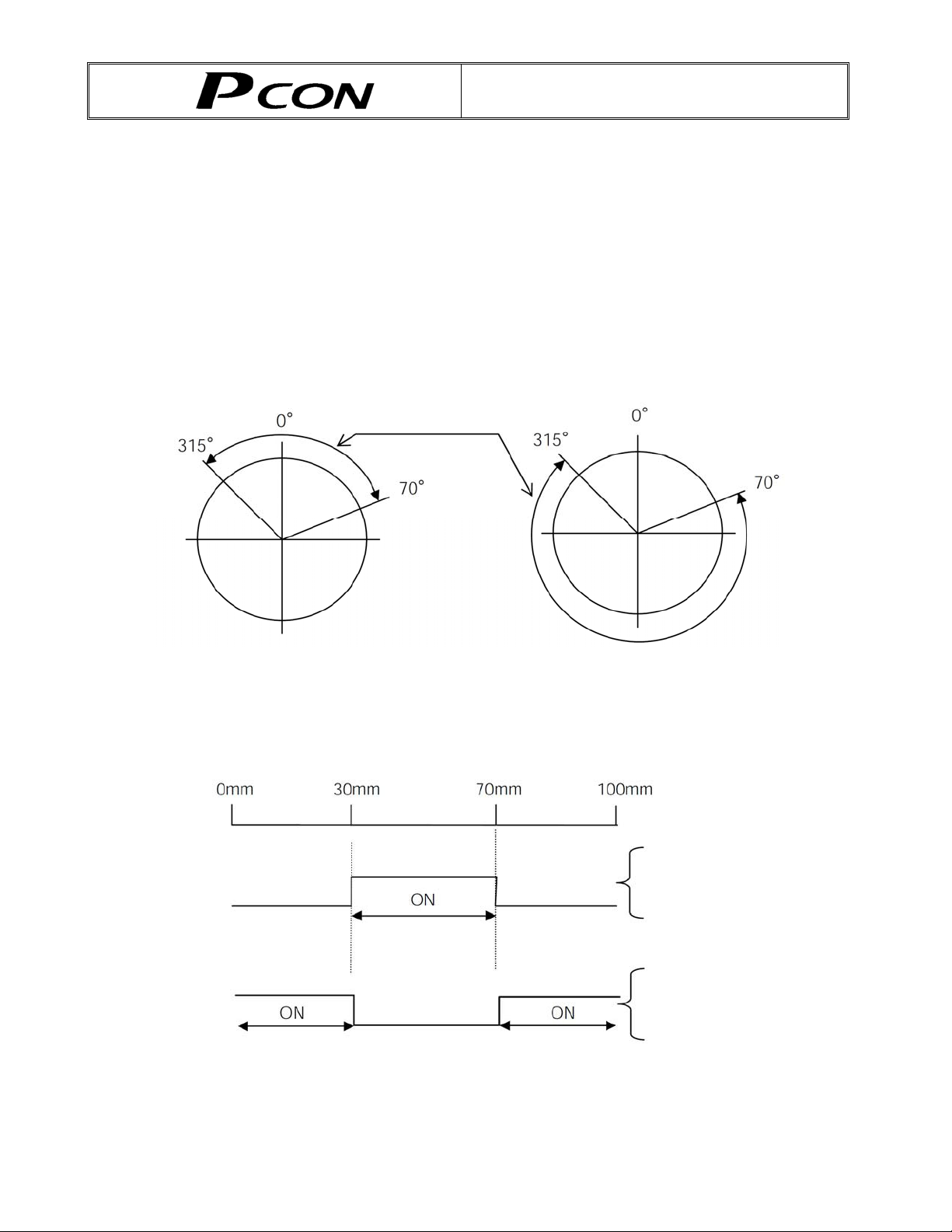
[Rotary actuator in index mode]
Zone signal ON range
Set value Set value
Zone setting+: 70q Zone setting+: 315q
Zone setting-: 315q Zone setting-: 70q
[Linear axis]
Current position
Zone signal output
Zone signal output
Set value
Zone setting+: 70 mm
Zone setting-: 30 mm
Set value
Zone setting+: 30 mm
Zone setting-: 70 mm
Page 6

Page 7

CAUTION
1. Use Environment
PCON controllers can be used in an environment of pollution degree 2 or equivalent.
2. PC Software and Teaching Pendant Models
New functions have been added to the entire PCON controller series.
To support these new features, the communication protocol has been changed to the general Modbus
(Modbus-compliant) mode. As a result, the existing PC software programs and teaching pendants
compatible with RCP2 controllers can no longer be used.
If you are using this controller, use a compatible PC software program and/or teaching pendant selected
from the following models.
skrameRrebmunledoM
PC software RCM-101-***
Teaching pendant CON-T, RCM-T
Simple teaching pendant RCM-E
Data setting unit RCM-P
Touch panel display RCM-PM-01 Not compatible with RCP2 controllers
All are compatible with existing RCP2
controllers
3. Recommendation for Backing up Latest Data
This product uses nonvolatile memory to store the position table and parameters. Normally the memory will
retain the stored data even after the power is disconnected. However, the data may be lost if the nonvolatile
memory becomes faulty.
We strongly recommend that the latest position table and parameter data be backed up so that the data
can be restored quickly when the controller must be replaced for a given reason.
The data can be backed up using the following methods:
[1] Save to a CD or FD from the PC software.
[2] Create a position table sheet or parameter sheet and keep a written record of backup.
Page 8

CAUTION
4. Initial Parameter Settings at Startup
After applying power, at least the three parameters specified below must be set in accordance with the
specific application.
Inappropriate settings of these parameters will prevent the controller from operating properly, so exercise
due caution.
For details on how to set the parameters, refer to “Parameter Settings” in the operation manual for the PC
or teaching pendant.
[1] Selecting the PIO pattern
This controller provides six PIO pattern types to meet the needs of various applications.
To select a desired type, set a corresponding value from 0 to 5 in parameter No. 25 (PIO pattern
selection).
The factory setting is “0 [Standard type].”
Parameter No.
25 setting
0 Standard type
A basic type supporting 64 positioning points and two zone outputs.
* How to set zone boundaries within which to output a zone signal:
Zone boundaries are set using parameter Nos. 1 and 2 for one zone output, and in
the position table for another zone output.
1 Teaching type
In this type, 64 positioning points and one zone output (boundaries are set in the
position table) are supported.
In addition to the normal positioning mode, the user can also select the teaching
mode in which the actuator can be jogged via commands from a PLC and the
current actuator position can be written to a specified position.
(Note 1) Jog commands from a PLC are also accepted in the positioning mode.
(Note 2) Positions can be rewritten by approximately 100,000 times.
2 256-point positioning type
The number of positioning points is increased to 256, so only one zone output is
available (boundaries are set in the position table).
3 512-point positioning type
The number of positioning points is increased to 512, so no zone output is available.
4 7-point type
The number of positioning points is limited to seven to offer separate direct
command inputs and position complete outputs for respective positions.
PLC ladder sequence circuits can be designed easily.
Feature of PIO pattern
5 3-point type
Use of the controller as an air cylinder is assumed in this type.
Position complete output signals function differently in this type, compared to the 7point type.
Specifically, the signal functions not only to “indicate position complete,” but also to
“detect a position” in the same manner as auto-switches of an air cylinder.
Page 9

CAUTION
[2] Enabling/disabling the servo ON input signal (SON)
The servo ON input signal has been added to allow for servo ON/OFF control on the PLC side.
Depending on the needs, therefore, the user must enable/disable this signal.
To select a desired setting, set “0” or “1” in parameter No. 21 (Servo ON input disable selection).
Enable (use) 0
Disable (do not use) 1
The factory setting is “0 [Enable].”
[3] Enabling/disabling the pause signal (*STP)
The pause signal uses the contact b logic to provide a failsafe function.
Therefore, this signal must remain ON in normal conditions of use.
Since there are applications where this signal is not used, a parameter is provided to disable the pause
signal so it doesn’ t have to be turned ON.
To select a desired setting, set “0” or “1” in parameter No. 15 (Pause input disable selection).
Enable (use) 0
Disable (do not use) 1
The factory setting is “0 [Enable].”
5. Using a Rotary Actuator in Multi-rotation Specification
Rotary actuators of multi-rotation specification models let you select multi-rotation operation or limited-rotation
operation using a parameter.
5.1 Notes
Pay attention to the setting of the PIO pattern parameter for the controllers specified below.
Each controller does not support relative coordination specification in the PIO pattern specified.
[1] PCON-C/CG: PIO pattern = 5 (User parameter No. 25)
[2] PCON-CY: PIO pattern = 0 (User parameter No. 25)
5.2 Applicable Models
Actuators
RCP2-RTCL-I-28P-30-360-*
Controllers
*-IP82-C-NOCP*-063-02-P82-I-LBTR-2PCR
*-IP82-GC-NOCP*-063-03-P82-I-LBTR-2PCR
*-IP82-YC-NOCP*-063-02-P82-I-LCTR-2PCR
PCON-SE-28PI-*
Page 10

Page 11

CE Marking
If a compliance with the CE Marking is required, please follow Overseas Standards Compliance Manual
(ME0287) that is provided separately.
Page 12

Page 13

Table of Contents
Safety Guide .................................................................................................................... 1
1. Overview ................................................................................................................... 9
1.1 Introduction..........................................................................................................................9
1.2 How to Read the Model Specification................................................................................10
1.3 System Configuration ........................................................................................................ 11
1.3.1 Internal Drive-Power Cutoff Relay Type (PCON-C/CF)................................................ 11
1.3.2 External Drive-Power Cutoff Relay Type (PCON-CG).................................................. 12
1.4 Procedure from Unpacking to Test Operation and Adjustment ..........................................13
1.5 Warranty............................................................................................................................ 15
1.5.1 Warranty Period.............................................................................................................15
1.5.2 Scope of Warranty.........................................................................................................15
1.5.3 Honoring the Warranty...................................................................................................15
1.5.4 Limited Liability..............................................................................................................15
1.5.5 Conditions of Conformance with Applicable Standards/Regulations, Etc.,
and Applications ........................................................................................................... 16
1.5.6 Other Items Excluded from Warranty............................................................................ 16
2. Specifications .......................................................................................................... 17
2.1 Basic Specifications...........................................................................................................17
2.2 Name and Function of Each Part of the Controller ............................................................18
2.3 External Dimensions..........................................................................................................20
3. Installation and Noise Elimination............................................................................ 21
3.1 Installation Environment ....................................................................................................21
3.2 Power Supply ....................................................................................................................21
3.3 Noise Elimination and Grounding ......................................................................................22
3.4 Heat Radiation and Installation..........................................................................................23
4. Wiring ...................................................................................................................... 24
4.1 Internal Drive-Power Cutoff Relay Type (PCON-C/CF) .....................................................24
4.1.1 External Connection Diagram....................................................................................... 24
4.1.2 Wiring the Power Supply/Emergency-Stop Switch....................................................... 25
4.2 External Drive-Power Cutoff Relay Type (PCON-CG) .......................................................32
4.2.1 External Connection Diagram....................................................................................... 32
4.2.2 Wiring the Power Supply/Emergency-Stop Switch....................................................... 33
4.3 Connecting the I/O Cables ................................................................................................36
z PIO pattern 0 [Standard Type].............................................................................................. 36
z PIO pattern 1 [Teaching Type] ............................................................................................. 37
z PIO pattern 2 [256-piont mode] ............................................................................................ 38
z PIO pattern 3 [512-piont mode] ............................................................................................ 39
z PIO pattern 4 [Solenoid valve mode 1]................................................................................. 40
z PIO pattern 5 [Solenoid valve mode 2]................................................................................. 41
4.4 Connecting the Actuator ....................................................................................................43
4.4.1 Connecting the PCON-C/CG and Actuator................................................................... 43
4.4.2 Connecting the PCON-CF and Actuator....................................................................... 45
4.5 Connecting the Communication Cable ..............................................................................46
Page 14

5. I/O Signal Control and Signal Functions.................................................................. 47
5.1 Interface Circuit
5.1.1 External Input Specifications......................................................................................... 47
5.1.2 External Output Specifications...................................................................................... 48
5.2 PIO Patterns and Signal Assignments
5.2.1 Explanation of Signal Names........................................................................................ 50
z PIO pattern = 0: Positioning mode [Standard type]..............................................................50
PIO pattern = 1: Teaching mode [Teaching type] ................................................................ 51
z
z PIO pattern = 2: 256-point mode [256-point type]................................................................ 52
z PIO pattern = 3: 512-point mode [512-point type]................................................................ 53
z PIO pattern = 4: Solenoid valve mode 1 [7- point type]........................................................54
z PIO pattern = 5: Solenoid valve mode 2 [3-point type].........................................................55
5.2.2 Signal Assignment Table for Respective PIO Patterns................................................. 56
.................................................................................................................47
...............................................................................49
5.3 Details of I/O Signal Functions ..........................................................................................57
5.3.1. Details of Each Input Signal.......................................................................................... 57
Operating mode (RMOD) ..................................................................................................... 57
Start (CSTR) ......................................................................................................................... 57
Command position number (PC1 to PC256)........................................................................ 57
Pause (*STP)........................................................................................................................ 58
Home return (HOME) ...........................................................................................................58
Servo ON (SON)................................................................................................................... 58
Alarm reset (RES) ................................................................................................................ 58
Brake release (BKRL)........................................................................................................... 59
Operation mode (MODE)...................................................................................................... 59
Current-position write (PWRT) ............................................................................................. 59
Manual operation switching (JISL) ....................................................................................... 59
Jog (JOG+, JOG-) ................................................................................................................60
Direct position command (ST0 to ST6) [7-point type] .......................................................... 60
Movement to each position (ST0 to ST2) [3-point type]....................................................... 61
5.3.2 Details of Each Output Signal....................................................................................... 62
Operating mode status (RMDS) ...........................................................................................62
Completed position number (PM1 to PM256) ...................................................................... 62
Moving (MOVE) ....................................................................................................................62
Position complete (PEND).................................................................................................... 62
Home return completion (HEND) ......................................................................................... 63
Zone (ZONE1, ZONE2) ........................................................................................................ 63
Current operation mode (MODES)....................................................................................... 63
Write completion (WEND) ....................................................................................................63
Movement complete at each position (PE0 to PE6) [7-point type]....................................... 64
Position detection output at each position (LS0 to LS2) [3-point type] ................................ 64
Ready (SV) ........................................................................................................................... 64
Alarm (*ALM) ........................................................................................................................ 64
Emergency stop (*EMGS) .................................................................................................... 65
Load output judgment status (LOAD)................................................................................... 65
Torque level status (TRQS).................................................................................................. 65
Output Signal Changes in Each Mode ................................................................................. 65
Page 15

6. Data Entry <Basics>................................................................................................ 66
6.1 Description of Position Table .............................................................................................66
6.1.1 Relationship of Push Force at Standstill and Current-Limiting Value ...........................70
6.2 Explanation of Modes ........................................................................................................70
6.2.1 Positioning Mode Push = 0........................................................................................... 70
6.2.2 Push & Hold Mode Push = Other than 0 ...................................................................... 70
6.2.3 Torque Check Function in Push & Hold Operation .......................................................73
6.2.4 Speed Change during Movement ................................................................................. 75
6.2.5 Operation at Different Acceleration and Deceleration Settings .................................... 75
6.2.6 Pause............................................................................................................................ 76
6.2.7 Zone Signal Output ....................................................................................................... 76
6.2.8 Home Return.................................................................................................................77
6.2.9
6.2.10 Overview of 7-point Type .............................................................................................. 79
6.2.11 Overview of 3-point Type .............................................................................................. 81
Overview of Teaching Type........................................................................................... 78
6.3 Notes on the ROBO Gripper..............................................................................................83
6.4 Power-saving Modes at Standby Positions........................................................................85
6.5 Using a Rotary Actuator in Multi-rotation Specification ......................................................88
6.5.1 How to Use ...................................................................................................................88
7. Operation <Practical Steps> .................................................................................... 89
7.1 How to S
7.1.1 Timings after Power On ................................................................................................ 89
Procedure after initial startup until actuator adjustment .................................................... 89
Procedure of Normal Operation......................................................................................... 91
7.1.2 Position Table and Parameter Settings Required for Operation................................... 93
Startup adjustment............................................................................................................. 93
Full-scale operation............................................................................................................ 94
tart.......................................................................................................................89
Safety speed during manual feed ...................................................................................... 93
Speed override for movement commands from the PLC .................................................. 93
Saving energy when the actuator stands by for a long time
after the power has been turned on................................................................................... 94
Saving energy when the actuator stands by after completing
the home return operation effected by the HOME input signal.......................................... 94
Saving energy when the actuator stands by for a long time at the target position............ 94
Output mode of complete signal ........................................................................................ 94
7.2 Home Return Operation ....................................................................................................95
7.2.1 Method Using the HOME Input Signal (PIO Pattern = 0 to 4) ...................................... 95
7.2.2 Method Used When No HOME Input Signal Is Available (PIO Pattern = 5)................. 97
7.3 Positioning Mode (Back and Forth Movement between Two Points) .................................98
7.4 Push & Hold Mode...........................................................................................................
7.4.1 Return Action after Push & Hold by Relative Coordinate Specification......................
100
102
7.5 Speed Change during Movement ....................................................................................103
7.6 Operation at Different Acceleration and Deceleration Settings ........................................105
7.7 Pause ..............................................................................................................................107
7.8 Zone Signal Output..........................................................................................................109
7.9 Incremental Moves .......................................................................................................... 112
7.9.1 Judgment Method of End Position.............................................................................. 114
7.9.2 Notes on Incremental Mode........................................................................................ 115
7.10 Jogging/Teaching Using PIO ...........................................................................................118
7.11 Operation in 7-point Type ................................................................................................ 120
7.12 Operation in 3-point Type ................................................................................................124
Page 16

8. Parameter Settings................................................................................................ 128
8.1 Parameter Table ..............................................................................................................128
8.2 Detail Explanation of Parameters ....................................................................................130
8.2.1 Parameters Relating to the Actuator Stroke Range.................................................... 130
z Soft limit (No.3/4 LIMM/LIML) ..................................................................................... 130
z Software limit margin (No. 88 SWLM) ........................................................................ 130
z Zone boundary (1: No.1/2 ZONM/ZONL 2: No.23/24 ZNM2/ZNL2)........................... 131
z Home return direction (No.5 ORG)............................................................................. 132
z Home return offset (No.22 OFST) .............................................................................. 132
8.2.2 Parameters Relating to the Actuator Operating Characteristics................................. 132
z PIO jog speed (No.26 IOJV) ....................................................................................... 132
z Software limit margin (No. 88 SWLM) ........................................................................ 130
z Zone boundary (1: No.1/2 ZONM/ZONL 2: No.23/24 ZNM2/ZNL2)........................... 131
z Home return direction (No.5 ORG)............................................................................. 132
Home return offset (No.22 OFST) .............................................................................. 132
z
8.2.2 Parameters Relating to the Actuator Operating Characteristics................................. 132
z PIO jog speed (No.26 IOJV) ....................................................................................... 132
PIO inching distance (No.48 IOID) ............................................................................. 132
z
z Default speed (No.8 VCMD) ....................................................................................... 132
z Default acceleration/deceleration (No.9 ACMD)......................................................... 133
z Default positioning band (in-position) (No.10 INP) ..................................................... 133
z Current-limiting value at standstill during positioning (No.12 SPOW) ........................ 133
z Current-limiting value during home return (No.13 ODPW)......................................... 133
z Home sensor input polarity (No. 18, LS)..................................................................... 133
z Speed override (No.46 OVRD) ................................................................................... 133
z Default direction of excited-phase signal detection (No.28 PHSP) ............................ 134
z Excited-phase signal detection time (No.29 PHSP) ................................................... 134
z Safety speed (No.35 SAFV) ....................................................................................... 134
z Automatic servo-off delay time (No.36 ASO1/No.37 ASO2/No.38 ASO3)................. 135
z Default standstill mode (No.53 HSTP)........................................................................ 135
z Push speed (No.34 PSHV) ......................................................................................... 136
z Push completion judgment time (No.6 PSWT)........................................................... 136
z Enable function (No.42 FDIO4) ..................................................................................137
z Polarity of home check sensor input (No.43 AIOF) ....................................................137
z Load output judgment time (No.50 LDWT)................................................................. 137
z Torque check range (No.51 TRQZ)............................................................................ 138
z Ball screw lead length (No.77 LEAD) ......................................................................... 138
z Axis operation type (No.78 ATYP).............................................................................. 138
z Rotational axis mode selection (No.79 ATYP) ...........................................................138
z Shortcut selection for rotational axis (No.80 ATYP) ...................................................138
z Absolute unit (No.83 ETYP)........................................................................................ 139
z Current-limiting value at standstill after missing work part in push & hold operation
(No. 91 PSFC)................................................................................................................. 139
8.2.3 Parameters Relating to the External Interface............................................................ 140
z PIO pattern selection (No.25 IOPN) ........................................................................... 140
z Movement command type (No.27 FPIO).................................................................... 141
z Pause input disable selection (No.15 FPIO)............................................................... 142
z Servo ON input disable selection (No.21 FPIO) ......................................................... 142
z Home-return input disable selection (No.40 FPIO)..................................................... 142
z Operating-mode input disable selection (No.41 FPIO)............................................... 142
z Output mode of position complete signal (No.39 FPIO)............................................. 143
z SIO communication speed (No.16 BRSL) ..................................................................143
z Minimum delay time for slave transmitter activation (No.17 RTIM)............................ 143
z Silent interval multiplier (No.45 SIVM)........................................................................ 144
Page 17

8.2.4 Servo Gain Adjustment............................................................................................... 145
z Servo gain number (No.7 PLG0) ................................................................................ 145
z Speed loop proportional gain (No.31 VLPG) .............................................................. 145
z Speed loop integral gain (No.32 VLPT)...................................................................... 146
z Torque filter time constant (No.33 TRQF) .................................................................. 146
9. PC/Teaching Pendant Connection Method in Multi-axis Configurations ................ 147
9.1 Connection Example .......................................................................................................147
9.2 SIO Converter (Optional).................................................................................................148
9.3 Address Switch................................................................................................................150
9.4 Connection Cables ..........................................................................................................150
9.5 Detail Connection Diagram..............................................................................................151
10. Troubleshooting..................................................................................................... 152
10.1 Action to Be Taken upon Occurrence of Problem ............................................................152
10.2 Alarm Level Classification ...............................................................................................153
10.3 Alarm Description Output Using PIO ...............................................................................154
10.4 Alarm Description and Cause/Action ...............................................................................155
(1) Message level alarms......................................................................................................... 155
(2) Cold-start level alarms........................................................................................................ 160
10.5 Messages Displayed during Operation Using the Teaching Pendant ..............................162
10.6 Specific Problems............................................................................................................165
z I/O signals cannot be exchanged with the PLC.................................................................. 165
z
The ALM lamp illuminates when the power is input. .......................................................... 165
z The SV lamp does not illuminate when the servo ON signal is
input after the power was input.
z Home return ends in the middle in a vertical application....................................................166
z Noise occurs during downward movements in a vertical application................................. 166
z Vibration occurs when the actuator is stopped................................................................... 166
z The actuator overshoots when decelerated to a stop. ....................................................... 166
z The home and target positions sometimes shift................................................................. 166
z The speed is slow during push & hold operation................................................................ 166
z The actuator moves only a half of, or twice as much as, the specified movement............ 166
z A servo error occurred while the actuator was moving (ROBO Gripper)........................... 167
z Abnormal operation results when the servo is turned ON after the power ON.................. 168
z The SV lamp blinks............................................................................................................. 168
......................................................................................... 165
* Appendix.................................................................................................................... 169
List of Specifications of Connectable Actuators.........................................................................169
Correlation diagram of speed and loading capacity for the slider type (motor-straight type).....181
Correlation diagram of speed and loading capacity for the slider type (motor-reversing type)..182
Correlation diagram of speed and loading capacity for the standard rod type...........................183
Correlation diagram of speed and loading capacity for the single-guide type ...........................184
Correlation diagram of speed and loading capacity for the double-guide type..........................185
Correlation diagram of speed and loading capacity for the dustproof/splash-proof type ...........186
Correlation diagram of speed and load capacity for the high-thrust type ..................................187
Correlation diagram of speed and loading capacity for the RCP3 slider type............................188
Correlation diagram of speed and loading capacity for the RCP3 table type ............................189
Page 18

Push Force and Current-limiting Value......................................................................................190
Fault check and replacement of the cooling fan ........................................................................198
Example of Basic PCON Positioning Sequence........................................................................200
Recording of Parameters ..........................................................................................................203
Change History ..........................................................................................................................205
Page 19

1
Safety Guide
“Safety Guide” has been written to use the machine safely and so prevent personal injury or property
damage beforehand. Make sure to read it before the operation of this product.
Safety Precautions for Our Products
The common safety precautions for the use of any of our robots in each operation.
No.
1 Model
Operation
Description
Selection
Description
Ɣ This product has not been planned and designed for the application where
high level of safety is required, so the guarantee of the protection of
human life is impossible. Accordingly, do not use it in any of the following
applications.
1) Medical equipment used to maintain, control or otherwise affect human
life or physical health.
2) Mechanisms and machinery designed for the purpose of moving or
transporting people (For vehicle, railway facility or air navigation facility)
3) Important safety parts of machinery (Safety device, etc.)
Ɣ Do not use the product outside the specifications. Failure to do so may
considerably shorten the life of the product.
Ɣ Do not use it in any of the following environments.
1) Location where there is any inflammable gas, inflammable object or
explosive
2) Place with potential exposure to radiation
3) Location with the ambient temperature or relative humidity exceeding
the specification range
4) Location where radiant heat is added from direct sunlight or other large
heat source
5) Location where condensation occurs due to abrupt temperature
changes
6) Location where there is any corrosive gas (sulfuric acid or hydrochloric
acid)
7) Location exposed to significant amount of dust, salt or iron powder
8) Location subject to direct vibration or impact
Ɣ For an actuator used in vertical orientation, select a model which is
equipped with a brake. If selecting a model with no brake, the moving part
may drop when the power is turned OFF and may cause an accident such
as an injury or damage on the work piece.
Page 20

No.
Operation
Description
Description
2 Transportation Ɣ When carrying a heavy object, do the work with two or more persons or
utilize equipment such as crane.
Ɣ When the work is carried out with 2 or more persons, make it clear who is
to be the leader and who to be the follower(s) and communicate well with
each other to ensure the safety of the workers.
Ɣ When in transportation, consider well about the positions to hold, weight
and weight balance and pay special attention to the carried object so it
would not get hit or dropped.
Ɣ Transport it using an appropriate transportation measure.
The actuators available for transportation with a crane have eyebolts
attached or there are tapped holes to attach bolts. Follow the instructions
in the operation manual for each model.
Ɣ Do not step or sit on the package.
Ɣ Do not put any heavy thing that can deform the package, on it.
Ɣ When using a crane capable of 1t or more of weight, have an operator
who has qualifications for crane operation and sling work.
Ɣ When using a crane or equivalent equipments, make sure not to hang a
load that weighs more than the equipment’s capability limit.
Ɣ Use a hook that is suitable for the load. Consider the safety factor of the
hook in such factors as shear strength.
Ɣ Do not get on the load that is hung on a crane.
Ɣ Do not leave a load hung up with a crane.
Ɣ Do not stand under the load that is hung up with a crane.
3 Storage and
Preservation
Ɣ The storage and preservation environment conforms to the installation
environment. However, especially give consideration to the prevention of
condensation.
Ɣ Store the products with a consideration not to fall them over or drop due to
an act of God such as earthquake.
4 Installation
and Start
(1) Installation of Robot Main Body and Controller, etc.
Ɣ Make sure to securely hold and fix the product (including the work part). A
fall, drop or abnormal motion of the product may cause a damage or injury.
Also, be equipped for a fall-over or drop due to an act of God such as
earthquake.
Ɣ Do not get on or put anything on the product. Failure to do so may cause
an accidental fall, injury or damage to the product due to a drop of
anything, malfunction of the product, performance degradation, or
shortening of its life.
Ɣ When using the product in any of the places specified below, provide a
sufficient shield.
1) Location where electric noise is generated
2) Location where high electrical or magnetic field is present
3) Location with the mains or power lines passing nearby
4) Location where the product may come in contact with water, oil or
chemical droplets
2
Page 21

3
No.
Operation
Description
4 Installation
and Start
Description
(2) Cable Wiring
Ɣ Use our company’s genuine cables for connecting between the actuator
and controller, and for the teaching tool.
Ɣ Do not scratch on the cable. Do not bend it forcibly. Do not pull it. Do not
coil it around. Do not insert it. Do not put any heavy thing on it. Failure to
do so may cause a fire, electric shock or malfunction due to leakage or
continuity error.
Ɣ Perform the wiring for the product, after turning OFF the power to the unit,
so that there is no wiring error.
Ɣ When the direct current power (+24V) is connected, take the great care of
the directions of positive and negative poles. If the connection direction is
not correct, it might cause a fire, product breakdown or malfunction.
Ɣ Connect the cable connector securely so that there is no disconnection or
looseness. Failure to do so may cause a fire, electric shock or malfunction
of the product.
Ɣ Never cut and/or reconnect the cables supplied with the product for the
purpose of extending or shortening the cable length. Failure to do so may
cause the product to malfunction or cause fire.
(3) Grounding
Ɣ The grounding operation should be performed to prevent an electric shock
or electrostatic charge, enhance the noise-resistance ability and control
the unnecessary electromagnetic radiation.
Ɣ For the ground terminal on the AC power cable of the controller and the
grounding plate in the control panel, make sure to use a twisted pair cable
with wire thickness 0.5mm
2
(AWG20 or equivalent) or more for grounding
work. For security grounding, it is necessary to select an appropriate wire
thickness suitable for the load. Perform wiring that satisfies the
specifications (electrical equipment technical standards).
Ɣ Perform Class D Grounding (former Class 3 Grounding with ground
resistance 100: or below).
Page 22

No.
4 Installation
Operation
Description
and Start
Description
(4) Safety Measures
Ɣ When the work is carried out with 2 or more persons, make it clear who is
to be the leader and who to be the follower(s) and communicate well with
each other to ensure the safety of the workers.
Ɣ When the product is under operation or in the ready mode, take the safety
measures (such as the installation of safety and protection fence) so that
nobody can enter the area within the robot’s movable range. When the
robot under operation is touched, it may result in death or serious injury.
Ɣ Make sure to install the emergency stop circuit so that the unit can be
stopped immediately in an emergency during the unit operation.
Ɣ Take the safety measure not to start up the unit only with the power turning
ON. Failure to do so may start up the machine suddenly and cause an
injury or damage to the product.
Ɣ Take the safety measure not to start up the machine only with the
emergency stop cancellation or recovery after the power failure. Failure to
do so may result in an electric shock or injury due to unexpected power
input.
Ɣ When the installation or adjustment operation is to be performed, give
clear warnings such as “Under Operation; Do not turn ON the power!” etc.
Sudden power input may cause an electric shock or injury.
Ɣ Take the measure so that the work part is not dropped in power failure or
emergency stop.
Ɣ Wear protection gloves, goggle or safety shoes, as necessary, to secure
safety.
Ɣ Do not insert a finger or object in the openings in the product. Failure to do
so may cause an injury, electric shock, damage to the product or fire.
Ɣ When releasing the brake on a vertically oriented actuator, exercise
precaution not to pinch your hand or damage the work parts with the
actuator dropped by gravity.
5 Teaching Ɣ When the work is carried out with 2 or more persons, make it clear who is
to be the leader and who to be the follower(s) and communicate well with
each other to ensure the safety of the workers.
Ɣ Perform the teaching operation from outside the safety protection fence, if
possible. In the case that the operation is to be performed unavoidably
inside the safety protection fence, prepare the “Stipulations for the
Operation” and make sure that all the workers acknowledge and
understand them well.
Ɣ When the operation is to be performed inside the safety protection fence,
the worker should have an emergency stop switch at hand with him so that
the unit can be stopped any time in an emergency.
Ɣ When the operation is to be performed inside the safety protection fence,
in addition to the workers, arrange a watchman so that the machine can
be stopped any time in an emergency. Also, keep watch on the operation
so that any third person can not operate the switches carelessly.
Ɣ Place a sign “Under Operation” at the position easy to see.
Ɣ When releasing the brake on a vertically oriented actuator, exercise
precaution not to pinch your hand or damage the work parts with the
actuator dropped by gravity.
* Safety protection Fence : In the case that there is no safety protection
fence, the movable range should be indicated.
4
Page 23

5
No.
Operation
Description
Description
6 Trial Operation Ɣ When the work is carried out with 2 or more persons, make it clear who is
to be the leader and who to be the follower(s) and communicate well with
each other to ensure the safety of the workers.
Ɣ After the teaching or programming operation, perform the check operation
one step by one step and then shift to the automatic operation.
Ɣ When the check operation is to be performed inside the safety protection
fence, perform the check operation using the previously specified work
procedure like the teaching operation.
Ɣ Make sure to perform the programmed operation check at the safety
speed. Failure to do so may result in an accident due to unexpected
motion caused by a program error, etc.
Ɣ Do not touch the terminal block or any of the various setting switches in
the power ON mode. Failure to do so may result in an electric shock or
malfunction.
7 Automatic
Operation
Ɣ Check before starting the automatic operation or rebooting after operation
stop that there is nobody in the safety protection fence.
Ɣ Before starting automatic operation, make sure that all peripheral
equipment is in an automatic-operation-ready state and there is no alarm
indication.
Ɣ Make sure to operate automatic operation start from outside of the safety
protection fence.
Ɣ In the case that there is any abnormal heating, smoke, offensive smell, or
abnormal noise in the product, immediately stop the machine and turn
OFF the power switch. Failure to do so may result in a fire or damage to
the product.
Ɣ When a power failure occurs, turn OFF the power switch. Failure to do so
may cause an injury or damage to the product, due to a sudden motion of
the product in the recovery operation from the power failure.
Page 24

No.
8 Maintenance
Operation
Description
and Inspection
Description
Ɣ When the work is carried out with 2 or more persons, make it clear who is
to be the leader and who to be the follower(s) and communicate well with
each other to ensure the safety of the workers.
Ɣ Perform the work out of the safety protection fence, if possible. In the case
that the operation is to be performed unavoidably inside the safety
protection fence, prepare the “Stipulations for the Operation” and make
sure that all the workers acknowledge and understand them well.
Ɣ When the work is to be performed inside the safety protection fence,
basically turn OFF the power switch.
Ɣ When the operation is to be performed inside the safety protection fence,
the worker should have an emergency stop switch at hand with him so that
the unit can be stopped any time in an emergency.
Ɣ When the operation is to be performed inside the safety protection fence,
in addition to the workers, arrange a watchman so that the machine can
be stopped any time in an emergency. Also, keep watch on the operation
so that any third person can not operate the switches carelessly.
Ɣ Place a sign “Under Operation” at the position easy to see.
Ɣ For the grease for the guide or ball screw, use appropriate grease
according to the Operation Manual for each model.
Ɣ Do not perform the dielectric strength test. Failure to do so may result in a
damage to the product.
Ɣ When releasing the brake on a vertically oriented actuator, exercise
precaution not to pinch your hand or damage the work parts with the
actuator dropped by gravity.
Ɣ The slider or rod may get misaligned OFF the stop position if the servo is
turned OFF. Be careful not to get injured or damaged due to an
unnecessary operation.
Ɣ Pay attention not to lose the cover or untightened screws, and make sure
to put the product back to the original condition after maintenance and
inspection works.
Use in incomplete condition may cause damage to the product or an injury.
* Safety protection Fence : In the case that there is no safety protection
fence, the movable range should be indicated.
9 Modification
and Dismantle
Ɣ Do not modify, disassemble, assemble or use of maintenance parts not
specified based at your own discretion.
10 Disposal Ɣ When the product becomes no longer usable or necessary, dispose of it
properly as an industrial waste.
Ɣ When removing the actuator for disposal, pay attention to drop of
components when detaching screws.
Ɣ Do not put the product in a fire when disposing of it.
The product may burst or generate toxic gases.
11 Other Ɣ Do not come close to the product or the harnesses if you are a person
who requires a support of medical devices such as a pacemaker. Doing so
may affect the performance of your medical device.
Ɣ See Overseas Specifications Compliance Manual to check whether
complies if necessary.
Ɣ For the handling of actuators and controllers, follow the dedicated
operation manual of each unit to ensure the safety.
6
Page 25
7
Alert Indication
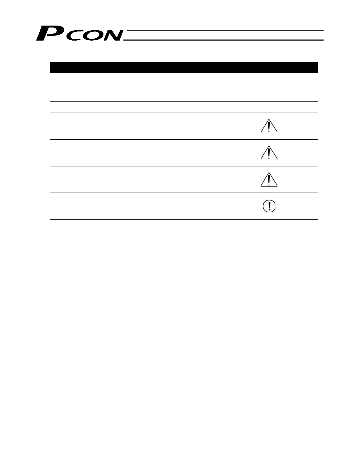
The safety precautions are divided into “Danger”, “Warning”, “Caution” and “Notice” according to the
warning level, as follows, and described in the Operation Manual for each model.
Level Degree of Danger and Damage Symbol
Danger
Warning
Caution
Notice
This indicates an imminently hazardous situation which, if the
product is not handled correctly, will result in death or serious injury.
This indicates a potentially hazardous situation which, if the product
is not handled correctly, could result in death or serious injury.
This indicates a potentially hazardous situation which, if the product
is not handled correctly, may result in minor injury or property
damage.
This indicates lower possibility for the injury, but should be kept to
use this product properly.
Danger
Warning
Caution
Notice
Page 26

8
Page 27

9
1. Overview
1.1 Introduction
This product is a dedicated RCP2 / RCP3 actuator controller that provides the same functions of the RCP2
controller as well as a set of new functions designed to achieve greater convenience and safety.
The product also provides a power-saving function in response to growing energy-saving needs.
The key features and functions are listed below.
z More positioning points
The standard type supports up to 64 points, while the extended types can handle up to 512 points. Availability
of more positioning points is ideal for production lines where many types of products are produced in small
volumes.
z Setting of zone output boundaries for each position in the position table
Before, zone output boundaries were set by parameters and therefore fixed. To add flexibility, new fields
have been added to the position table so that different boundaries can be set for each position.
This feature is useful in preventing contact with surrounding equipment and reducing the tact time, among
others.
z Separate acceleration/deceleration settings
Acceleration and deceleration are now set in separate fields of the position table.
Depending on the material or shape of the load, it is desirable to reduce shock and vibration when the
actuator stops.
Since acceleration and deceleration can be set differently, only the deceleration value can be reduced to
make the deceleration curve more gradual.
z Limitation of feed speed in test operation and adjustment
The feed speed to be used in test operation and adjustment can be limited for added safety.
z Power-saving measures
In general, pulse motors consume more holding current in standstill state than AC servo motors. This product
provides a power-saving means to support situations where the actuator must stand by for a long period.
1. Overview
When actually starting up your system or if you have encountered any problem, also refer to the operation
manuals for the actuator, teaching pendant, PC software and other components used with the system, in
addition to this manual.
This manual does not cover all possible operations other than normal operations, or unexpected events
such as complex signal changes resulting from use of critical timings.
Accordingly, you should consider items not specifically explained in this manual as “prohibited.”
* We have made every effort to ensure precision of the information provided in this manual. Should you find an
error, however, or if you have any comment, please contact IAI.
Keep this manual in a convenient place so it can be referenced readily when necessary.
Page 28

1.2 How to Read the Model Specification
PCON - C - 56PI - NP - 2 - 0 - ABU - H
1. Overview
<Series>
<Type>
C: Positioner type with internal drive-
power cutoff relay
CG: Positioner type with external drive-
power cutoff relay
CF: High-output positioner type with internal
drive-power cutoff relay
<Actuator type>
[Motor flange size]
20P: 20, square
28P: 28, square
28SP: 28, square (RA3 type only)
42P: 42, square
56P: 56, square
86P: 86 square
[Encoder type]
I: Incremental
High-acceleration, loading
specification
Specified for connecting the
simple absolute unit
<Power-supply voltage>
0: 24 VDC
<I/O flat cable length>
0: No cable
2: 2 m
3: 3 m
5: 5 m
<Input/output signal pattern>
NP: NPN (Sink type)
PN: PNP (Source type)
DV: DeviceNet connection specification
CC: CC-Link connection specification
PR: PROFIBUS connection specification
CN: CompoNet connection specification
ML: MECHATROLINK connection
specification
EC: EtherCAT connection specification
EP: EtherNet/IP connection
specification
10
Page 29

11
1. Overview
1.3 System Configuration
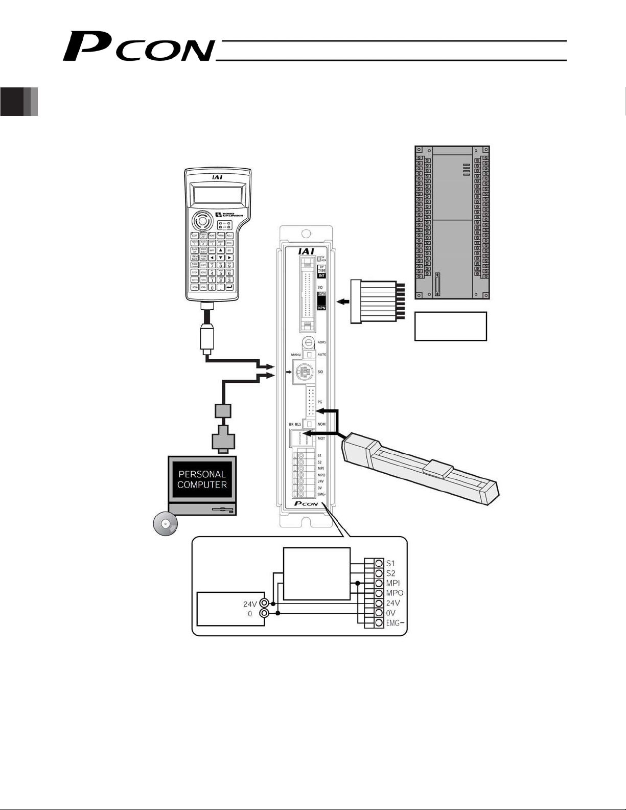
1.3.1 Internal Drive-Power Cutoff Relay Type (PCON-C/CF)
Standard teaching
pendant
<CON-T, RCM-T>
Supplied flat
cable
Host system <PLC>
24-VDC I/O
power supply
PC software
(optional)
RS232C type <RCM-101-MW>
USB type <RCM 101-USB>
PC
Input power
supply
24 VDC
RCP2 actuator
External EMG switch
24 V
0 V
Caution: Connect one end of the EMG switch to the 24-V output of the input power supply and the
other end to the S1 terminal. Also short the S2 and EMG terminals using a jumper wire.
Page 30
1.3.2 External Drive-Power Cutoff Relay Type (PCON-CG)
1. Overview
Standard teaching
pendant
<CON-t, RCM-T>
Host system <PLC>
Supplied flat
cable
24-VDC I/O
power supply
PC software
PC
(optional)
RS232C type <RCM-101-MW>
USB type <RCM 101-USB>
Input power
supply 24
VDC
RCP2 actuator
Motor drivepower cutoff
circuit
Safety relay
Contactor
12
Page 31

13
1. Overview
1.4 Procedure from Unpacking to Test Operation and Adjustment
If you are using this product for the first time, carry out each step by referring to the procedure below to ensure
that all necessary items are checked and all wires are connected correctly.
Check the content in the package
1
If you found any missing part or part specified for a different model, please contact your dealer.
z Controller
PCON-C
PCON-CG
PCON-CF
z Operation manual
<Options>
z Teaching pendant z PC software
RCM-T (standard) RC232C type <RCM-101-MW>
RCM-E (simple) RC232 type <RCM-101-USB>
RCM-P (data setting unit) (Software comes with connection cables.)
2
[1] Affix the actuator first, and then install the robot hand. o Refer to the operation manual for the applicable
[2] Install the controller. o Chapter 3, “Installation”
3
Installation
Wiring/connection
z Actuator z I/O flat cable
CB-PAC PIO* * *
z Motor cable
CB-RCP2-MA* * *
actuator.
z Encoder cable
CB-RCP2-PA* * *
x Wire the 24-V power supply.
x Connect the grounding wire to ground.
x Wire the emergency stop circuit and motor drive power supply.
x Connect the motor cable and encoder cable.
x Connect the I/O flat cable.
Turn on the power and check for alarms
4
Supply the 24-V power after confirming that the emergency stop circuit is not actuated.
If the monitor LED [SV/ALM] on the front face of the controller illuminates for two seconds and then turns off, the
controller is functioning properly. If [SV/ALM] illuminates in red, it means an alarm has generated. Connect a PC
or teaching pendant to check the nature of the alarm, and remove the cause by referring to Chapter 10,
“Troubleshooting.”
Set the PIO pattern/safety speed
5
Set the mode selector switch on the front face of the controller to the “MANU” side.
On the PC screen or teaching pendant, set the MANU operating mode to [Teaching mode: Enable safety
speed/Inhibit PIOs].
In this condition, set appropriate values in parameter No. 25 (PIO pattern selection) and parameter No. 35
(Safety speed).
* The factory-set PIO pattern and safety speed are “standard type” and “100 mm/s or less,” respectively. o
Chapter 8, “Parameter Settings”
Page 32

6
Confirm that the slider or rod is not contacting a mechanical end.
If the slider/rod is contacting a mechanical end, move it away from the mechanical end.
If the actuator is equipped with a brake, turn on the brake forced-release switch to forcibly release the brake
before moving the actuator.
The load may suddenly drop when the brake is released, so exercise due caution not to pinch your hand or
1. Overview
damage the robot hand by the falling load.
Turn on the servo from the PC or teaching pendant.
If the actuator enters a servo lock mode and the monitor LED [SV/ALM] on the front face of the controller
illuminates in green, the controller is functioning properly.
7
Confirm that the emergency stop circuit (or motor drive-power cutoff circuit) operates properly.
8
Perform home return first, and then set a target position in the “Position” field for each position in the position
table. Determine a desired position by finely adjusting the load or robot hand.
* Once a target position is set, all other fields (speed, acceleration/deceleration, positioning band, etc.) will be
* To ensure safety, it is recommended that the safety speed be enabled during initial movements.
Turn on the servo
Check the operation of the safety circuit
o Chapter 4, “Wiring”
Set a target position
automatically populated with their default values. o Chapter 6, “Position Table Settings”
To move the actuator at the actual speed set in the “Speed” field of the position table, change the MANU
operating mode to [Teaching mode 2: Disable safety speed/Inhibit PIOs].
Trial operation and adjustment
9
Set the mode selector switch on the front panel of the controller to the “AUTO” side.
Input a movement command from the PLC to perform positioning.
If necessary, perform fine adjustments including the items specified below:
x Vibration or noise may generate depending on the weight, material or shape of the load. If vibration or noise
is observed, lower the speed, acceleration and/or deceleration.
x To prevent contact with surrounding equipment or reduce the tact time, adjust the boundaries for each zone
output signal and also adjust the positioning band.
x Adjust the current-limiting value, judgment time and push speed to be used in push & hold operation.
Caution: Before changing any parameter, set the mode selector switch to the “MANU” side. Or,
keep the mode selector switch on the “AUTO” side and turn on the MODE input signal.
14
Page 33

15
1. Overview
1.5 Warranty
1.5.1 Warranty Period
One of the following periods, whichever is shorter:
18 months after shipment from our factory
12 months after delivery to a specified location
1.5.2 Scope of Warranty
Our products are covered by warranty when all of the following conditions are met. Faulty products covered
by warranty will be replaced or repaired free of charge:
(1) The breakdown or problem in question pertains to our product as delivered by us or our authorized dealer.
(2) The breakdown or problem in question occurred during the warranty period.
(3) The breakdown or problem in question occurred while the product was in use for an appropriate purpose
under the conditions and environment of use specified in the operation manual and catalog.
(4) The breakdown or problem in question was caused by a specification defect or problem, or by the poor
quality of our product.
Note that breakdowns due to any of the following reasons are excluded from the scope of warranty:
[1] Anything other than our product
[2] Modification or repair performed by a party other than us (unless we have approved such
modification or repair)
[3] Anything that could not be easily predicted with the level of science and technology available at the
time of shipment from our company
[4] A natural disaster, man-made disaster, incident or accident for which we are not liable
[5] Natural fading of paint or other symptoms of agin
[6] Wear, depletion or other expected result of use
[7] Operation noise, vibration or other subjective sensation not affecting function or maintenance
Note that the warranty only covers our product as delivered and that any secondary loss arising from a
breakdown of our product is excluded from the scope of warranty.
1.5.3 Honoring the Warranty
As a rule, the product must be brought to us for repair under warranty.
1.5.4 Limited Liability
[1] We shall assume no liability for any special damage, consequential loss or passive loss such as a loss of
expected profit arising from or in connection with our product.
[2] We shall not be liable for any program or control method created by the customer to operate our product
or for the result of such program or control method.
Page 34

1.5.5 Conditions of Conformance with Applicable Standards/Regulations, Etc., and Applications
(1)
(2) Our product is for general industrial use. It is not intended or designed for the applications specified below,
1. Overview
(3)
1.5.6 Other Items Excluded from Warranty
The price of the product delivered to you does not include expenses associated with programming, the dispatch
of engineers, etc. Accordingly, a separate fee will be charged in the following cases even during the warranty
period:
[1] Guidance for installation/adjustment and witnessing of test operation
[2] Maintenance and inspection
[3] Technical guidance and education on operating/wiring methods, etc.
[4] Technical guidance and education on programming and other items related to programs
If our product is combined with another product or any system, device, etc., used by the customer, the
customer must first check the applicable standards, regulations and/or rules. The customer is also
responsible for confirming that such combination with our product conforms to the applicable standards, etc.
In such a case we will not be liable for the conformance of our product with the applicable standards, etc.
which require a high level of safety. Accordingly, as a rule our product cannot be used in these applications.
Contact us if you must use our product for any of these applications:
[1] Medical equipment pertaining to maintenance or management of human life or health
[2] A mechanism or mechanical equipment intended to move or transport people (such as a vehicle,
railway facility or aviation facility)
[3] Important safety parts of mechanical equipment (such as safety devices)
[4] Equipment used to handle cultural assets, art or other irreplaceable items
Contact us at the earliest opportunity if our product is to be used in any condition or environment that
differs from what is specified in the catalog or operation manual.
16
Page 35

17
2. Specifications
2.1 Basic Specifications
Specification item
(Internal Drive-Power Cutoff
PCON-C
Relay Type)
PCON-CG
(External Drive-Power Cutoff
Relay Type)
PCON-CF
(Internal Drive-Power Cutoff
Relay Type)
Number of controlled axes 1 axis/unit
Supply voltage
Power-source
capacity
Actuator Rated Max. *2 Rated Max. *2 Rated Max. *3
20, 28P motor 0.4 A 0.4 A
35, 42, 56P motor 1.2 A
24 VDC r 10%
2.0 A
1.2 A
2.0 A
86P motor 4.2 A 6.0 A
Heat output 9.6 W 9.6 W 26.4 W
Control method Weak field-magnet vector control
Encoder resolution Incremental specification 800 Puls/rev
Positioning command Number of positioning points: 64 points (standard) to 512 points (maximum)
* The number of positioning points varies depending on the selected PIO
pattern.
Backup memory
Position data and parameters are saved in nonvolatile memory.
Serial EEPROM can be rewritten approx. 100,000 times.
PIO interface 24-VDC I/O
LED indicators SV (green) --- Servo on, ALM (red) --- Alarm present
Serial communication RS485, 1 channel (conforming to the Modbus protocol)
Electromagnetic-brake forced
release function
Cable length
NOM/BK RLS switch (front panel)
Actuator cable: 20 m or less
I/O flat cable: 5 m or less
Isolation strength
Environment
Surrounding air
temperature
Surrounding
humidity
Surrounding
environment
Storage
temperature
500 VDC, 10 M:
0to40qC
85%RH or less (non-condensing)
Refer to 3.1 Installation Environment
-10 to 65qC
Storage humidity 90%RH or less (non-condensing)
Vibration
resistance
10 to 57 Hz in XYZ directions / Pulsating amplitude: 0.035 mm (continuous),
0.075 mm (intermittent)
57 to 150 Hz in XYZ directions: 4.9 m/s
2
(continuous), 9.8 m/s
2
Protection class IP20
Cooling method Natural air cooling Forced air cooling
Weight 300 g or less 300 g or less 320 g or less
External dimensions 35 W x 175.5 H x 68.1 D mm
6SHFL¿FDWLRQV
*1 Rush current of around 5 to 12 times the rated current flows for approx. 1 to 2 msec
after the power is turned on. Take note that the value of rush current varies
according to the impedance of the power-supply line.
*2 Excitation detection operation is performed after the power is turned on. The
maximum current flows during this operation (normally for 100 msec).
Note, however, that approx. 6.0 A of current flows (for approx. 1 to 2 msec) if the
motor drive source is cut off and then turned on again.
*3 Excitation detection operation is performed after the power is turned on. The
maximum current flows during this operation (normally for 100 msec).
Note, however, that approx. 10.0 A of current flows (for approx. 1 to 2 msec) if the
motor drive source is cut off and then turned on again.
Caution: Position data, parameters, etc., are written to the EEPROM. Take note
that the EEPROM can be rewritten for up to approx. 100,000 times.
For the +24-V DC power supply,
select a unit of the “peak load
accommodation” specification or
having a sufficient allowance with
respect to the peak load. In
particular, exercise caution when
your system has a remote sensing
function.
Page 36

2.2 Name and Function of Each Part of the Controller
A
Connects the PLC and PIOs.
6SHFL¿FDWLRQV
Connects the teaching
pendant/PC.
Motor connector
Connects the motor cable.
PIO connector
Mode selector switch
SIO connector
The model name of the actuator to
be connected is indicated here.
Status indicator LEDs
SV (green) --- The servo is on
A blinking green light indicates
that the automatic servo-off
mode is active.
LM (red) --- An alarm is present.
The motor drive-power cutoff
circuit is indicated here.
The PIO pattern number is specified here.
The input/output signal pattern is indicated
here.
Address switch
Encoder connector
Connects the encoder cable.
Brake release switch
Power-supply
terminal block
Indication of PIO pattern number
If you have multiple systems and a different PIO pattern is used for each system, it is recommended that you
specify an applicable PIO pattern number on each controller to prevent confusion.
Explanation of input/output signal pattern
NPN --- Sink type
PNP --- Source type
Explanation of motor drive-power cutoff circuit
INT --- PCON-C/CF [Internal drive-power cutoff relay type]
EXT --- PCON-CG [External drive-power cutoff relay type]
Indication of model name of actuator to be connected
The type name, ball screw lead length and stroke of the applicable actuator are indicated. When connecting
the cables, check this information to confirm that they are connected to the correct actuator.
Example of indication:
RA4C
L: 5 mm
ST: 200
m The actuator type is RA4C.
m The ball screw lead length is 5 mm.
m The stroke is 200 mm.
18
Page 37

19
6SHFL¿FDWLRQV
Explanation of each switch
[1] Address switch
If multiple axes are used, the PC/teaching pendant must be plugged into/out of different connectors to
communicate with different axes.
To save the hassle, you can use link cables to connect all axes via SIO converters.
Under this method, however, the PC/teaching pendant must be able to identify each axis by the number
assigned to the axis.
This switch is used to set this number.
For details, refer to Chapter 9, “How to Connect a PC/Teaching Pendant to Multiple Axes.”
[2] Mode selector switch
This interlock switch is used to prevent unexpected movement or data rewrite as a result of duplicate
operation in which a movement command is input from the PLC and operation using the PC/teaching
pendant is performed at the same time.
AUTO: Always set to the “AUTO” side during auto operation using PIO signals from the PLC.
MANU: Always set to the “MANU” side during operation using the PC/teaching pendant.
[3] Brake release switch
When the actuator is equipped with a brake, this switch is used to forcibly release the brake.
RLS: Forcibly release the brake
NOR: Normal setting (The brake is released by the controller.)
U Warning: The load may suddenly drop when the brake is forcibly released, so exercise due caution
not to pinch your hand or damage the work part or robot hand by the falling load.
Explanation of power-supply terminal block
[1] PCON-C/CF [Internal drive-power cutoff relay type]
Provide a contact output for the emergency-stop button on the teaching pendant.
S1, S2
* Whether or not a teaching pendant is connected is determined by an internal
circuit. If no teaching pendant is connected, the S1 and S2 terminals are closed.
Provide a contact for cutting off the motor drive power. MPI and MPO represent the
MPI, MPO
input side and output side of the motor power supply, respectively. (Short these
terminals using a jumper wire if not used. The controller is shipped with MPI and MPO
shorted.)
24V Positive side of the 24-VDC input power supply
0V Negative side of the 24-VDC input power supply
EMG- Emergency-stop input
[2] PCON-CG [External driver-power cutoff relay type]
Provide a contact output for the emergency-stop button on the teaching pendant.
S1, S2
* Whether or not a teaching pendant is connected is determined by an internal
circuit. If no teaching pendant is connected, the S1 and S2 terminals are closed.
Motor drive-power cutoff contacts conforming to safety category 1
MPI, MPO
MPI and MPO represent the input side and output side of the motor power supply,
respectively. (Connect an external safety circuit.)
24V Positive side of the 24-VDC input power supply
0V Negative side of the 24-VDC input power supply
EMG- Emergency stop signal detection
Page 38

2.3 External Dimensions
An external view and dimensions of the product are shown below.
6SHFL¿FDWLRQV
178.5
5
1705 (Mounting dimension)
84
68.1
20
5
35
Page 39

21
3. Installation and Noise Elimination
Pay due attention to the installation environment of the controller.
3.1 Installation Environment
This product is capable for use in the environment of pollution degree 2
*1 Pollution Degree 2 : Environment that may cause non-conductive pollution or transient conductive pollution
by frost (IEC60664-1)
[1] Installation Environment
Do not use this product in the following environment.
• Location where the surrounding air temperature exceeds the range of 0 to 40°C
• Location where condensation occurs due to abrupt temperature changes
• Location where relative humidity exceeds 85%RH
• Location exposed to corrosive gases or combustible gases
• Location exposed to significant amount of dust, salt or iron powder
• Location subject to direct vibration or impact
• Location exposed to direct sunlight
• Location where the product may come in contact with water, oil or chemical droplets
• Environment that blocks the air vent [Refer to 3.3 Noise Elimination and Grounding]
When using the product in any of the locations specified below, provide a sufficient shield.
• Location subject to electrostatic noise
• Location where high electrical or magnetic field is present
• Location with the mains or power lines passing nearby
[2] Storage and Preservation Environment
• Storage and preservation environment follows the installation environment. Especially, when the product is
to be left for a long time, pay special attention to condensed water.
Unless specially specified, moisture absorbency protection is not included in the package when the machine
is delivered. In the case that the machine is to be stored in an environment where dew condensation is
anticipated, take the condensation preventive measures from outside of the entire package, or directly after
opening the package.
*1
or equivalent.
3. Installation and Noise Elimination
3.2 Power Supply
The power supply specification is 24 VDC r 10%.
(Supply current: 2 A max.: C/CG, 6 A: CF)
Page 40

3.3 Noise Elimination and Grounding
This section explains how to eliminate noise in the use of the controller.
(1) Wiring and power supply
[1] Provide a dedicated class D grounding using a wire with a size of 2.0 to 5.5 mm2or larger.
Controller
Use a cable of a
maximum possible
size and keep the
wiring length at a
minimum.
Metal frame
Class D grounding Good Avoid this grounding method.
3. Installation and Noise Elimination
[2] Precautions regarding wiring method
Use a twisted cable for connection to the 24-VDC external power supply.
Separate the controller cables from high-power lines such as a cable connecting to a power circuit. (Do not
bundle together the controller cables with high-power lines or place them in the same cable duct.)
When extending the supplied motor cable or encoder cable, consult IAI’s Technical Support.
(2) Noise sources and elimination
Among the numerous noise sources, solenoid valves, magnet switches and relays are of particular concern
when building a system. Noise from these sources can be eliminated by implementing the measures specified
below.
Other
equipment
Controller
Other
equipment
[1] AC solenoid valves, magnet switches and relays
Measure: Install a surge absorber in parallel with the coil.
Å Point
Install a surge absorber to each coil over a minimum wiring
length.
Installing a surge absorber to the terminal block or other part will
be less effective because of a longer distance from the coil.
22
Page 41

23
3. Installation and Noise Elimination
[2] DC solenoid valves, magnet switches and relays
Measure: Install a diode in parallel with the coil. Determine the diode capacity in accordance with the load
capacity.
In a DC circuit, connecting a diode in reverse polarity will damage the
diode, internal parts of the controller and/or DC power supply, so exercise
due caution.
3.4 Heat Radiation and Installation
Design the control panel size, controller layout and cooling method in such a way that the temperature around
the controller will not exceed 40qC.
Install the controller vertically on a wall, as shown below. Since cooling is provided by way of natural convection,
always observe this installation direction and provide a minimum clearance of 50 mm above and below the
controller to ensure sufficient natural airflows.
When installing multiple controllers side by side, providing a ventilation fan or fans above the controllers will help
maintain a uniform temperature around the controllers.
Keep the front panel of the controller away from the wall (enclosure) by at least 95 mm.
Fan
Regardless of whether your system consists of a single controller or multiple controllers, provide sufficient
clearances around each controller so that it can be installed/removed easily.
50 mm or more
50 mm or more
95 mm
or more
Airflow
Page 42

4. Wiring
4. Wiring
4.1 Internal Drive-Power Cutoff Relay Type (PCON-C/CF)
4.1.1 External Connection Diagram
An example of standard wiring is shown below.
(Note) The encoder cable shown in the example is the standard cable.
As for the robot cable, refer to 4.4.1 as the color of the cable is different.
Controller
Connection
detection circuit
Connected to teaching
pendant or PC
External EMG switch
Input power
supply 24
VDC
I/O flat cable
0 V (NPN
specification)
24 V (PNP
specification)
24 V (NPN
specification)
0 V (PNP
specification)
24-VDC power for
input/output signals
For details on I/O signal connection, refer
to 4.3, “Connecting the I/O Cables.”
Load
Load
Terminal block
Input
Output
Motor extension
Orange
Gray
White
Yellow
Pink
Yellow (Green)
Encoder extension
Yellow
Blue
Orange
Pink
Purple
Green
Brown
Gray
Red
Actuator
Motor
Encoder
Holding
brake
24
Brake release switch
Tighten together with the
mounting screw.
Page 43

25
4. Wiring
4.1.2 Wiring the Power Supply/Emergency-Stop Switch
(1) Wiring the power supply
S1
S2
Input power supply
24 VDC
(2 A max. per controller)
24V
0V
FG
To connect multiple controllers, provide a relay terminal block.
Use a power cable satisfying the following specifications:
Item Specification
Applicable wire length
Single wire: 1.0 / Stranded: 0.8 mm
Stripped wire length 10 mm
Temperature rating of
isolated sheath
60qC or above
* Use a flathead screwdriver with a blade tip of approx. 2.6 mm to push in the wire.
MPI
MPO
24V
0V
EMG-
2
, AWG size 18, (copper wire)
Page 44

(2) Wiring the emergency-stop switch
In many cases multiple controllers are used in a single system.
To provide an emergency-stop function for the entire system, the controller circuit is designed in such a way that
a single EMG switch is able to actuate an emergency stop in all connected controllers.
[Internal emergency-stop circuit]
Teaching pendant
PCON-C controller
4. Wiring
EMG signal
S1
S2
MPI
Input power supply
(2 A max.)
24V
0V
MPO
24V
0V
EMG-
Controller power
supply
(Note) The current consumption of the internal relay is 10 mA or less.
(Reference) Cutoff voltage Cutoff current
EMG switch on teaching pendant 30 VDC 3 A
[Example of recommended circuit]
24V
External EMG
reset switch
CR
External EMG circuit
PCON-C controller
EMG switch on
teaching pendant
(3A)
Connection detection circuit
Relay
0V
S2S1
CR
Coil current:
0.1 A or less
Motor power
supply
0V
Connection detection circuit
MP1
MPO
CR
EMG-
24V
Relay
0V
(Note) To cut off the motor drive power supply in conformance with safety category 2, connect 24V to the EMG
terminal and a contactor or other contact device to the MPI/MPO terminals. (Refer to 4.2.3; rush current:
8 A.)
26
Page 45

27
4. Wiring
Representative connection examples are explained below.
z Connecting the teaching pendant directly to the controller
[1] Connecting multiple controllers (8 units or less) using a single power supply
x Short the MPI and MPO terminals using a jumper wire. (The controller is shipped with these terminals
shorted.)
x Connect one end of the EMG signal to the 24-V output of the input power supply and the other end to the S1
terminal.
Then, provide connections by sequentially connecting the S2 terminal of controller 1 to the S1 terminal of
controller 2, the S2 terminal of controller 2 to the S1 terminal of controller 3, and so on, and connect the S2
terminal on the last controller to the EMG terminals on all controllers.
Use a relay terminal block for connection to the EMG terminals.
(Note) Do not connect two or more wires to one terminal.
Page 46

24V
EMG signal
S1
[Controller 1]
Teaching pendant
0V
S2
4. Wiring
MPI
MPO
24V
EMG-
Teaching pendant
S1
MPI
MPO
24V
EMG-
Teaching pendant
S1
Connection
detection circuit
Relay
[Controller 2]
Connection
detection circuit
Relay
[Controller 3]
0V
S2
0V
S2
28
MPI
MPO
24V
EMG-
Teaching pendant
S1
MPI
MPO
24V
EMG-
Connection
detection circuit
Relay
[Controller 4]
Connection
detection circuit
Relay
0V
S2
0V
Page 47

29
4. Wiring
©
[2] Using a power supply other than the input power supply
(Note) Use an auxiliary relay with a coil current of 0.1 A or less and connect a diode for coil surge absorption.
control
0V
EMG signal
S1
MPI
MPO
24V
0V
EMG-
MPI
MPO
24V
0V
EMG-
[Controller 1]
Teaching pendant
Connection
detection circuit
Relay
[Controller 2]
Teaching pendant
Connection
detection circuit
Relay
© 24V
S2
S2S1
[Controller 3]
Teaching pendant
MPI
MPO
24V
0V
EMG-
Connection
detection circuit
Relay
S2S1
CR
Page 48

[3] Enabling the EMG switch on the teaching pendant for the connected axis or axes only
4. Wiring
24V
EMG signal
CR
[Controller 1]
Teaching pendant
S1
MPI
MPO
detection circuit
24V
EMG-
[Controller 2]
Teaching pendant
S1
Connection
Relay
0V
S2
S2
CR
CR
0V
MPI
MPO
24V
EMG-
Teaching pendant
S1
MPI
MPO
24V
EMG-
Connection
detection circuit
Relay
[Controller 3]
Connection
detection circuit
Relay
0V
S2
0V
30
Page 49

31
4. Wiring
z Connecting the teaching pendant to a SIO converter
Configure the contact circuit for the EMG switch on the teaching pendant using EMG1/EMG2 on the
power/emergency-stop terminal block on the SIO converter.
(S1/S2 on the controller’s terminal block are not used.)
24V 0V
SIO converter
EMG signal
EMG2 EMG1
CR
Teaching pendant
MPI
MPO
24V
EMG-
CR
ON
OFF
Port switch
[Controller 1]
0V
Relay
MPI
MPO
24V
EMG-
MPI
MPO
24V
EMG-
[Controller 2]
0V
Relay
[Controller 3]
0V
Relay
Page 50

4. Wiring
4.2 External Drive-Power Cutoff Relay Type (PCON-CG)
4.2.1 External Connection Diagram
An example of standard wiring is shown below.
(Note) The encoder cable shown in the example is the standard cable.
As for the robot cable, refer to 4.4.1 as the color of the cable is different.
Controller
Connection
Connected to teaching
pendant or PC
Terminal block
Motor drivepower cutoff
circuit
Input power
supply 24
VDC
I/O flat cable
Motor extension
Orange
Gray
White
Yellow
Pink
Yellow (Green)
Encoder extension
cable
Actuator
Motor
0 V (NPN
specification)
24 V (PNP
specification)
24 V (NPN
specification)
0 V (PNP
specification)
24-VDC power for
input/output signals
For details on I/O signal connection, refer to
4.3, “Connecting the I/O Cables.”
Input
Output
Yellow
Blue
Orange
Pink
Purple
Green
Brown
Gray
Red
Brake release switch
Encoder
Holding brake
32
Page 51

33
4. Wiring
4.2.2 Wiring the Power Supply/Emergency-Stop Switch
(1) Wiring the power supply
S1
S2
Input power supply
24 VDC
(2 A max. per controller)
24V
0V
FG
To connect multiple controllers, provide a relay terminal block.
Use a power cable satisfying the following specifications:
Item Specification
Applicable wire length
Single wire: 1.0 / Stranded: 0.8 mm
Stripped wire length 10 mm
Temperature rating of
isolated sheath
60qC or above
* Use a flathead screwdriver with a blade tip of approx. 2.6 mm to push in the wire.
MPI
MPO
24V
0V
EMG-
2
, AWG size 18, (copper wire)
Page 52

4. Wiring
(2) Wiring the motor power cutoff relay
Explained below is a safety circuit conforming to safety category 2.
The user is responsible for implementing additional safety measures in the actual circuit configuration, such as
providing double contactor contacts to prevent fusing.
The circuit illustrated below is for reference purposes only.
x The input side of the motor drive power supply is connected to the MPI terminal, while the output side is
connected to the MPO terminal. Connect a contactor or other contact device to these terminals.
(Note) The rush current must be 8 A or less. The rated current is 2 A.
x The contact for the EMG switch on the teaching pendant is provided by the S1/S2 terminals.
(Note) When connecting the teaching pendant to a SIO converter, the contact for the EMG switch on the
teaching pendant is provided by the EMG1/EMG2 terminals on the SIO converter.
[Example of basic circuit]
Teaching pendant
EMG switch
(3A)
24V
0V
External EMG
reset switch
External EMG
circuit
S1
Connection
detection circuit
MC
Coil current: 0.1 A or less
MC
MC
(Rush-in current: 8 A,
rated current: 2 A)
(MAX. 2A)
S2
MPI
MPO
24V
0V
EMG-
Motor power
supply
Controller power
supply
PCON-CG controller
34
Page 53

35
4. Wiring
[Connection example of a multiple-axis configuration]
Input power supply
24V
0V
EMG signal
Connect to 24-V terminal
Connect to 0-V terminal
[Controller 1] [Controller 2] [Controller 3]
S1
S2
MPI
MPO
24V
0V
EMG-
S1
S2
MPI
MPO
24V
0V
EMG-
S1
S2
MPI
MPO
24V
0V
EMG-
Contactor
External reset switch
Safety relay unit
Phoenix contact (PSR-SCP-24UC-/ESA2/4X1/1X2/B)
Page 54

4.3 Connecting the I/O Cables
z PIO pattern 0 [Standard Type]
4. Wiring
Host system <PLC> end
+24 [V]
+24 [V]
Command position 1
Command position 2
Command position 4
Command position 8
Command position 16
Command position 32
Output side
Brake release
Operating mode
Home return
Pause
Start
Alarm reset
Servo ON
Completed position 1
Completed position 2
Completed position 4
Completed position 8
Completed position 16
Completed position 32
Moving
Zone output
Input side
Position zone output
Operating mode status
Home return completion
Position complete
Ready
Emergency stop
Alarm
0 [V]
0 [V]
Upper
stage
Lower
stage
Brown 1
Red 1
Orange 1
Yellow 1
Green 1
Blue 1
Purple 1
Gray 1
White 1
Black 1
Brown 2
Red 2
Orange 2
Yellow 2
Green 2
Blue 2
Purple 2
Gray 2
White 2
Black 2
Brown 3
Red 3
Orange 3
Yellow 3
Green 3
Blue 3
Purple 3
Gray 3
White 3
Black 3
Brown 4
Red 4
Orange 4
Yellow 4
Green 4
Blue 4
Purple 4
Gray 4
White 4
Black 4
Controller end
(signal abbreviation)
PIO
LOAD/TRQS
(Note) *STP, *ALM and *EMGS are based on the negative logic.
36
Page 55

37
4. Wiring
z PIO pattern 1 [Teaching Type]
Host system <PLC> end
+24 [V]
+24 [V]
Command position 1
Command position 2
Command position 4
Command position 8
Command position 16
Command position 32
Operation mode
Manual operation
switching
Output side
Operating mode
Completed position 1
Completed position 2
Completed position 4
Completed position 8
Completed position 16
Completed position 32
Current operation mode
Input side
Position zone output
Operating mode status
Home return completion
Position complete/write
Emergency stop
Jog+
Jog-
Home return
Pause
Start/currentposition write
Alarm reset
Servo ON
Moving
completion
Ready
Alarm
0 [V]
0 [V]
Upper
stage
Lower
stage
Brown 1
Red 1
Orange 1
Yellow 1
Green 1
Blue 1
Purple 1
Gray 1
White 1
Black 1
Brown 2
Red 2
Orange 2
Yellow 2
Green 2
Blue 2
Purple 2
Gray 2
White 2
Black 2
Brown 3
Red 3
Orange 3
Yellow 3
Green 3
Blue 3
Purple 3
Gray 3
White 3
Black 3
Brown 4
Red 4
Orange 4
Yellow 4
Green 4
Blue 4
Purple 4
Gray 4
White 4
Black 4
Controller end
(signal abbreviation)
PIO
(Note) *STP, *ALM and *EMGS are based on the negative logic.
Page 56

z PIO pattern 2 [256-piont mode]
4. Wiring
Host system <PLC> end
Upper
stage
+24 [V]
+24 [V]
Command position 1
Command position 2
Command position 4
Command position 8
Command position 16
Command position 32
Command position 64
Command position 128
Output side
Brake release
Operating mode
Home return
Pause
Start
Alarm reset
Servo ON
Completed position 1
Completed position 2
Completed position 4
Completed position 8
Completed position 16
Completed position 32
Completed position 64
Completed position 128
Input side
Position zone output
Operating mode status
Home return completion
Position complete
Emergency stop
Ready
Alarm
0 [V]
0 [V]
Lower
stage
Brown 1
Red 1
Orange 1
Yellow 1
Green 1
Blue 1
Purple 1
Gray 1
White 1
Black 1
Brown 2
Red 2
Orange 2
Yellow 2
Green 2
Blue 2
Purple 2
Gray 2
White 2
Black 2
Brown 3
Red 3
Orange 3
Yellow 3
Green 3
Blue 3
Purple 3
Gray 3
White 3
Black 3
Brown 4
Red 4
Orange 4
Yellow 4
Green 4
Blue 4
Purple 4
Gray 4
White 4
Black 4
Controller end
PIO (signal abbreviation)
LOAD/TRQS
38
(Note) *STP, *ALM and *EMGS are based on the negative logic.
Page 57

39
4. Wiring
z PIO pattern 3 [512-piont mode]
Host system <PLC> end
Upper
stage
Command position 1
Command position 2
Command position 4
Command position 8
Command position 16
Command position 32
Command position 64
Command position 128
Command position 256
Output side
Brake release
Operating mode
Home return
Pause
Start
Alarm reset
Servo ON
Completed position 1
Completed position 2
Completed position 4
Completed position 8
Completed position 16
Completed position 32
Completed position 64
Completed position 128
Input side
Completed position 256
Operating mode status
Home return completion
Position complete
Emergency stop
Ready
Alarm
Lower
stage
Brown 1
Red 1
Orange 1
Yellow 1
Green 1
Blue 1
Purple 1
Gray 1
White 1
Black 1
Brown 2
Red 2
Orange 2
Yellow 2
Green 2
Blue 2
Purple 2
Gray 2
White 2
Black 2
Brown 3
Red 3
Orange 3
Yellow 3
Green 3
Blue 3
Purple 3
Gray 3
White 3
Black 3
Brown 4
Red 4
Orange 4
Yellow 4
Green 4
Blue 4
Purple 4
Gray 4
White 4
Black 4
Controller end
(signal abbreviation)
PIO
LOAD/TRQS
(Note) *STP, *ALM and *EMGS are based on the negative logic.
Page 58

z PIO pattern 4 [Solenoid valve mode 1]
4. Wiring
Host system <PLC> end
Direct position command 0
Direct position command 1
Direct position command 2
Direct position command 3
Direct position command 4
Direct position command 5
Direct position command 6
Output side
Input side
Brake release
Operating mode
Home return
Pause
Alarm reset
Servo ON
Movement complete 0
Movement complete 1
Movement complete 2
Movement complete 3
Movement complete 4
Movement complete 5
Movement complete 6
Zone output
Position zone output
Operating mode status
Home return completion
Position complete
Ready
Emergency stop
Alarm
Upper
stage
Lower
stage
Brown 1
Red 1
Orange 1
Yellow 1
Green 1
Blue 1
Purple 1
Gray 1
White 1
Black 1
Brown 2
Red 2
Orange 2
Yellow 2
Green 2
Blue 2
Purple 2
Gray 2
White 2
Black 2
Brown 3
Red 3
Orange 3
Yellow 3
Green 3
Blue 3
Purple 3
Gray 3
White 3
Black 3
Brown 4
Red 4
Orange 4
Yellow 4
Green 4
Blue 4
Purple 4
Gray 4
White 4
Black 4
Controller end
(signal abbreviation)
PIO
LOAD/TRQS
40
(Note) *STP, *ALM and *EMGS are based on the negative logic.
Page 59

41
4. Wiring
z PIO pattern 5 [Solenoid valve mode 2]
Host system <PLC> end
Upper
stage
Rear end move
Front end move
Intermediate point move
Output side
Brake release
Operating mode
Alarm reset
Servo ON
Rear end detected
Front end detected
Intermediate point
Zone output
Input side
Position zone output
Operating mode status
Home return completion
Emergency stop
detected
Ready
Alarm
Lower
stage
Brown 1
Red 1
Orange 1
Yellow 1
Green 1
Blue 1
Purple 1
Gray 1
White 1
Black 1
Brown 2
Red 2
Orange 2
Yellow 2
Green 2
Blue 2
Purple 2
Gray 2
White 2
Black 2
Brown 3
Red 3
Orange 3
Yellow 3
Green 3
Blue 3
Purple 3
Gray 3
White 3
Black 3
Brown 4
Red 4
Orange 4
Yellow 4
Green 4
Blue 4
Purple 4
Gray 4
White 4
Black 4
Controller end
(signal abbreviation)
PIO
(Note) *STP, *ALM and *EMGS are based on the negative logic.
Page 60

Caution: When performing a continuity check of the flat cable, pay due attention not to expand the female
pins in the connector. It may cause contact failure and disable normal operation of the controller.
Black 4
4. Wiring
Brown 3
Black 2
Brown 1
Lower stage
Upper stage
20A
1A
20B
1B
42
Page 61

43
4. Wiring
r
r
r
4.4 Connecting the Actuator
4.4.1 Connecting the PCON-C/CG and Actuator
Use dedicated extension cables to wire the controller and actuator.
(1) RCP2 motor cable
Model: CB-RCP2-MA
( indicates the cable length L. Example. 080 = 8 m)
Pin layout
Pin layout
(Front view)
Cable model marking
Controller end
Signal name
Pin No.
Cable colo
Orange
Gray
White
Yellow
Pink
Yellow (Green)
Housing: 1-1318119-3 (AMP)
Contact: 1318107-1
(2) RCP2 encoder cable/encoder robot cable
Model for standard cable: CB-RCP2-PB
Model for robot cable: CB-RCP2-PB-RB (optional)
( indicates the cable length L. Example. 080 = 8 m)
Pin layout
(Front view) Cable model marking
Controller end
Pin No.
Signal
name
Cable colo
Standard cable
Blue (Red 1)
White
Red
Gray
Brown
Green
Purple
Pink
Robot cable
Orange (Black 2)
Orange (Red 2)
Orange (Black 1)
Orange (Red 1)
Light gray (Black 1)
Light gray (Red 1)
White (Black 1)
White (Red 1)
Description
Home check
sensor
Brake power
Encoder phase
A signal
Encoder phase
B signal
(Front view)
Actuator end
Pin No.
Housing: SLP-06V (J.S.T. Mfg.)
Socket contact: BSF-21T-P1.4
Pin layout
(Front view)
Actuator end
Signal
Pin No.
name
Yellow
Orange
Blue
Ground
Housing: PHDR-16VS (J.S.T. Mfg.)
Contact: SPHD-001T-P0.5
Yellow (Black 1)
Pink (Red 1)
Pink (Black 1)
Ground
Encoder control signal
Encoder powe
Shield
Housing: XMP-18V (J.S.T. Mfg.)
Contact: BXA-001T-P0.6
Retainer: XMS-09V
Page 62

4. Wiring
)
)
)
)
(3) RCP3 motor/encoder integrated cable
Model: CB-PCS-MPA
( indicates the cable length L. Example. 080 = 8 m)
(Front view)
Controller end
Housing: D-2100D 1-1318119-3 (Hirose)
Contact: D-2 1318105-1
Cable model marking
Actuator end
Pin No.
Pin No.
Signal
name
Signal
name
Cable name
Black
White
Red
Green
Yellow
Brown
Description
Home check
sensor
Brake power
Encoder phase A
signal
Encoder phase B
signal
Encoder control signal
Encoder power
Cable name
Pink (red dots)
Pink (blue dots)
White (red dots)
White (blue dots)
Pink (red dots)
Orange (blue dots)
Gray (red dots)
Gray (blue dots)
Orange (continuous
red dots
Orange (continuous
blue dots
Gray (continuous
red dots
Gray (continuous
blue dots
Pin No.
Shield
Housing: PHDR-16VS (J.S.T. Mfg.)
Contact: SPHD-001T-P0.5
Shield
Housing: D-1100D1-1827863-1 (AMP)
Contact: D-1 1827570-2
44
Page 63

45
4. Wiring
r
4.4.2 Connecting the PCON-CF and Actuator
r
r
Use dedicated extension cables to wire the controller and actuator.
(1) RCP2 motor cable
Model: CB-RCP2-MA
( indicates the cable length L. Example. 080 = 8 m)
Pin layout
(Front view)
Cable model marking
Controller end
Signal name
Pin No.
Housing: 1-1318119-3 (AMP)
Contact: 1318107-1
Cable colo
Orange
Gray
White
Yellow
Pink
Yellow
(Green)
Housing: SLP-06V (J.S.T. Mfg.)
Socket contact: BSF-21T-P1.4
(2) RCP2 encoder cable/encoder robot cable (dedicated cable for PCON-CF)
Model for standard cable: CB-RFA-PA
Model for robot cable: CB-RF-PA -RB (optional)
( indicates the cable length L. Example. 080 = 8 m)
Pin layout
(Front view)
Controller end
Cable model marking
Pin No.
(Front view)
Actuator end
(Front view)
Actuator end
Pin layout
Pin layout
Signal
Pin No.
name
Housing: PHDR-16VS (J.S.T. Mfg.)
Contact: SPHD-001T-P0.5
Cable colo
Standard cable
Red
Gray
Brown
Green
Purple
Pink
Yellow
Blue
Orange
Ground
Robot cable
Purple
White
Blue
White
Yellow
White
Green
White
Red
Ground
Description
Brake power
Encoder phase
A signal
Encoder phase
B signal
Encoder control signal
Encoder powe
Shield
Signal
Pin No.
name
Housing: XMP-18V (J.S.T. Mfg.)
Contact: BXA-001T-P0.6
Retainer: XMS-09V
Page 64

4.5 Connecting the Communication Cable
Connect the communication cable to the SIO connector.
Pin assignments of the
cable-end connector
4. Wiring
RS485 conversion adapter end
Brown
Yellow
Red
Orange
Blue
Green
Signal name
5V
SGA
GND
SGB
GND
5V
Pin No.
1
2
3
4
5
6
Cable color
Shorting wire UL1004AWG28 (black)
Shielded, not connected
CB-RCA-SIO***
Pin No.
1
2
3
4
5
6
7
8
Signal name
EMGS
EMGA
EMGB
FG
SGA
SGB
5V
24V
GND
Controller end
Cable color
Centered
Orange
Brown/Green
-
Black
-
Red/Blue
Black
Shielded
6
3
1
8
5
2
46
Page 65

47
5. I/O Signal Control and Signal Functions
5.1 Interface Circuit
The standard interface specification of the controller is NPN, but the PNP specification is also available as an
option.
To prevent confusion during wiring, the NPN and PNP specifications use the same power line configuration.
Accordingly, there is no need to reverse the power signal assignments for a PNP controller.
5.1.1 External Input Specifications
Item Specification
Number of input points 16 points
Input voltage
Input current 5 mA/point
Operating voltage
Leak current 1 mA or less/point
Isolation method Photocoupler
Internal circuit configuration
[NPN specification]
External power supply
+24V
Each input
24 VDC r 10%
ON voltage: Min. 18 V (3.5 mA)
OFF voltage: Max. 6 V (1 mA)
Controller
P24V
R=680 :
R=5.6 k:
5. I/O Signal Control and Signal Functions
Internal circuit
R =22 k:
C=0.1 PF
[PNP specification]
External power supply
+24V
Each input
Controller
N
R=68 :
R=5.6 k:
Internal circuit
R=22 k:
C=0.1 PF
Page 66

5.1.2 External Output Specifications
Item Specification
Number of output points 16 points
Rated load voltage 24 VDC
Maximum current 50 mA/point
Residual voltage 2 V or less
Isolation method Photocoupler
Internal circuit configuration
[NPN specification]
Controller
P24V
Load
Internal circuit
5. I/O Signal Control and Signal Functions
[PNP specification]
Internal circuit
Controller
Each output
Each output
N
P24V
Load
Load
Load
External power
supply
+24V
External power
supply
+24V
48
N
Page 67

49
5. I/O Signal Control and Signal Functions
5.2 PIO Patterns and Signal Assignments
This controller provides six PIO pattern types to meet the needs of various applications.
To select a desired type, set a corresponding value from 0 to 5 in parameter No. 25 (PIO pattern selection).
The features of each PIO pattern are explained below:
Parameter No.
25 setting
0
1
2
3
4
5
Feature of PIO pattern
Positioning mode (Standard type)
A basic type supporting 64 positioning points and two zone outputs.
* How to set zone boundaries within which to output a zone signal:
Zone boundaries are set using parameter Nos. 1 and 2 for one zone output, and in the
position table for another zone output.
Teaching mode (Teaching type)
In this type, 64 positioning points and one zone output (boundaries are set in the
position table) are supported.
In addition to the normal positioning mode, the user can also select the teaching mode
in which the actuator can be jogged via I/Os and the current actuator position can be
written to a specified position.
(Note) Positions can be rewritten by approximately 100,000 times.
256-point mode (256-point positioning type)
The number of positioning points is increased to 256, so only one zone output is
available (boundaries are set in the position table).
512-point mod (512-point positioning)
The number of positioning points is increased to 512, so no zone output is available.
Solenoid valve mode 1 (7-point type)
The number of positioning points is limited to seven to offer separate direct command
inputs and movement complete outputs.
PLC ladder sequence circuits can be designed easily.
Solenoid valve mode 2 (3-point type)
Use of the controller as an air cylinder is assumed in this type.
Movement complete output signals function differently in this type, compared to the 7point type.
Specifically, the signal functions not only to “indicate movement complete,” but also to
“detect a position” in the same manner as auto-switches of an air cylinder. Push & hold
operation cannot be performed.
Quick reference table for functions available under each PIO pattern ({: Available, X: Not available)
Number of
No. 25
positioning
points
0 64 points
1 64 points x
2 256 points
3 512 points
4 7 points
5 3 points
Brake
release
{{
{{
{{
{{
{
Input signals Output signals
Home
return
{{{
x x x
Jog
x x
x x x
x x x x x
x x
Current-
position
write
Zone
{{{
x
{{
{{
Position
zone
{{
{
Ready
x
x
x
(Note) For “Zone” and “Position zone,” different methods are used to set boundaries defining the range within
which the zone signal will turn ON.
“Zone” is set by parameter Nos. 1 and 2, and thus its setting will become effective after home return is
completed.
“Position zone” is set in the “Zone+” and “Zone-“ fields for each position number in the position table,
and thus its setting will become effective after a movement command is input.
Page 68

5.2.1 Explanation of Signal Names
The following explains the signal names, and gives a function overview of each signal.
In the explanation of operation timings provided in a later section, each signal is referenced by its selfexplanatory name for clarity. If necessary, however, such as when marker tubes are inserted as a termination of
the flat cable, use the signal abbreviations.
z PIO pattern = 0: Positioning mode [Standard type]
Category Signal name
Command position
number
Input
Brake release BKRL
Operating mode RMDO
Home return HOME
*Pause *STP
Start CSTR
Alarm reset RES
Servo ON SON
Completed position
number
5. I/O Signal Control and Signal Functions
Moving MOVE
Zone ZONE1
Position zone PZONE
Output
Operating mode status RMDS
Home return
completion
Position complete PEND
Ready SV
*Emergency stop *EMGS
*Alarm *ALM
Load output judgment
status
Torque level status TRQS
abbreviation
PC1
PC2
PC4
PC8
PC16
PC32
PM1
PM2
PM4
PM8
PM16
PM32
HEND
LOAD
Signal
Function overview
The target position number is input.
A command position number must be specified by 6 ms before the
start signal (CSTR) turns ON.
This signal is used on an actuator equipped with a brake to forcibly
release the brake.
This signal switches the operating mode between AUTO and MANU.
Home return operation is started at a rise edge of this signal.
ON: Actuator can be moved, OFF: Actuator decelerates to a stop
The actuator will start moving at a rise edge of this signal.
An alarm is reset at a rise edge of this signal.
The servo remains ON while this signal is ON.
The servo remains OFF while this signal is OFF.
The relevant position number is output when positioning has
completed.
The signal will turn OFF when the next start signal is received.
It is used by the PLC to check if the commanded position has
definitively been reached, and also to provide a position interlock, etc.
This signal will remain ON while the actuator is moving, and OFF
while the actuator is standing still.
It is used to determine whether the actuator is moving or paused.
This signal becomes effective after home return. It will turn ON when
the current actuator position enters the range set by the parameters
and remain ON until the actuator exits the range.
This signal becomes effective after a position movement command is
input. It will turn ON when the current actuator position enters the
range specified in the position table and remain ON until the actuator
exits the range.
This signal will remain OFF during the AUTO mode, and ON during
the MANU mode.
This signal is OFF immediately after the power is input, and turns ON
when home return has completed.
This signal turns ON when the target position was reached and the
actuator has entered the specified in-position range.
It is used to determine whether positioning has completed.
This signal is always output once the servo is turned ON and the
controller is ready to operate.
When this signal is OFF, it means that an emergency stop is being
actuated.
This signal remains ON in normal conditions of use and turns OFF
when an alarm generates.
This signal will turn ON when the command torque exceeds the
threshold while the actuator is inside the check range.
Note) Dedicated output signal for the PCON-CF
This signal will turn ON when the motor current reaches the
threshold.
Note) Dedicated output signal for the PCON-CF
50
Page 69

51
5. I/O Signal Control and Signal Functions
z PIO pattern = 1: Teaching mode [Teaching type]
Category Signal name
Command position
number
Operation mode MODE Mode selection (ON: Teaching mode, OFF: Normal mode)
Jog/inching switching JISL OFF: Jog, ON: Inching
+jog/inching movement JOG+
-jog/inching movement JOG-
Input
Operating mode RMDO This signal switches the operating mode between AUTO
Signal
abbreviation
PC1
PC2
PC4
PC8
PC16
PC32
The target position number is input.
A command position number must be specified by 6 ms before
the start signal (CSTR) turns ON.
The actuator will start jogging or inching in the positive
direction at an ON edge of this signal.
The actuator will start jogging or inching in the negative
direction at an ON edge of this signal.
and MANU.
Home return HOME Home return operation is started at a rise edge of this signal.
ON: Actuator can be moved, OFF: Actuator decelerates to a
stop
When this signal has remained ON for 20 msec or longer, the
current position will be stored under the position number
selected by PC1 to PC32.
The servo remains ON while this signal is ON.
The servo remains OFF while this signal is OFF.
The relevant position number is output when positioning has
completed.
The signal will turn OFF when the next start signal is received.
It is used by the PLC to check if the commanded position has
definitively been reached, and also to provide a position
interlock, etc.
This signal will remain ON while the actuator is moving, and
OFF while the actuator is standing still.
It is used to determine whether the actuator is moving or
paused.
This signal becomes effective after a position movement
command is input. It will turn ON when the current actuator
position enters the range specified in the position table and
remain ON until the actuator exits the range.
This signal will remain OFF during the AUTO mode, and ON
during the MANU mode.
This signal is OFF immediately after the power is input, and
turns ON when home return has completed.
This signal turns ON when the target position was reached
and the actuator has entered the specified in-position range.
It is used to determine whether positioning has completed.
This signal is output upon completion of writing to the
nonvolatile memory in response to a current-position write
command (PWRT).
This signal is always output once the servo is turned ON and
the controller is ready to operate.
This signal remains ON in normal conditions of use and turns
OFF when an alarm generates.
Output
*Pause *STP
Start CSTR The actuator will start moving at a rise edge of this signal.
Current-position write PWRT
Alarm reset RES An alarm is reset at a rise edge of this signal.
Servo ON SON
PM1
PM2
Completed position
number
Moving MOVE
Mode status MODES ON: Teaching mode, OFF: Normal mode
Position zone PZONE
Operating mode status RMDS
Home return
completion
Position complete PEND
Write completion WEND
Ready SV
*Emergency stop *EMGS OFF: Emergency stop has been actuated
*Alarm *ALM
PM4
PM8
PM16
PM32
HEND
Function overview
Page 70

z PIO pattern = 2: 256-point mode [256-point type]
Category Signal name
PC1
PC2
PC4
Command position
number
Input
5. I/O Signal Control and Signal Functions
Output
Brake release BKRL
Operating mode RMDO
Home return HOME Home return operation is started at a rise edge of this signal.
*Pause *STP
Start CSTR The actuator will start moving at a rise edge of this signal.
Alarm reset RES An alarm is reset at a rise edge of this signal.
Servo ON SON
Completed position
number
Position zone PZONE
Operating mode status RMDS
Home return
completion
Position complete PEND
Ready SV
*Emergency stop *EMGS OFF: Emergency stop has been actuated
*Alarm *ALM
Load output judgment
status
Torque level status TRQS
PC8
PC16
PC32
PC64
PC128
PM1
PM2
PM4
PM8
PM16
PM32
PM64
PM128
HEND
LOAD
Signal
abbreviation
Function overview
The target position number is input.
A command position number must be specified by 6 ms before
the start signal (CSTR) turns ON.
This signal is used on an actuator equipped with a brake to
forcibly release the brake.
This signal switches the operating mode between AUTO and
MANU.
ON: Actuator can be moved, OFF: Actuator decelerates to a
stop
The servo remains ON while this signal is ON.
The servo remains OFF while this signal is OFF.
The relevant position number is output when positioning has
completed.
The signal will turn OFF when the next start signal is received.
It is used by the PLC to check if the commanded position has
definitively been reached, and also to provide a position
interlock, etc.
This signal becomes effective after a position movement
command is input. It will turn ON when the current actuator
position enters the range specified in the position table and
remain ON until the actuator exits the range.
This signal will remain OFF during the AUTO mode, and ON
during the MANU mode.
This signal is OFF immediately after the power is input, and
turns ON when home return has completed.
This signal turns ON when the target position was reached
and the actuator has entered the specified in-position range.
It is used to determine whether positioning has completed.
This signal is always output once the servo is turned ON and
the controller is ready to operate.
This signal remains ON in normal conditions of use and turns
OFF when an alarm generates.
This signal will turn ON when the command torque exceeds
the threshold while the actuator is inside the check range.
Note) Dedicated output signal for the PCON-CF
This signal will turn ON when the motor current reaches the
threshold.
Note) Dedicated output signal for the PCON-CF
52
Page 71

53
5. I/O Signal Control and Signal Functions
z PIO pattern = 3: 512-point mode [512-point type]
Category Signal name
Command position
number
Input
Output
Brake release BKRL
Operating mode RMDO
Home return HOME Home return operation is started at a rise edge of this signal.
*Pause *STP
Start CSTR The actuator will start moving at a rise edge of this signal.
Alarm reset RES An alarm is reset at a rise edge of this signal.
Servo ON SON
Completed position
number
Operating mode status RMDS
Home return
completion
Position complete PEND
Ready SV
*Emergency stop *EMGS OFF: Emergency stop has been actuated
*Alarm *ALM
Load output judgment
status
Torque level status TRQS
Signal
abbreviation
PC1
PC2
PC4
PC8
PC16
PC32
PC64
PC128
PC256
PM1
PM2
PM4
PM8
PM16
PM32
PM64
PM128
PC256
HEND
LOAD
The target position number is input.
A command position number must be specified by 6 ms before
the start signal (CSTR) turns ON.
This signal is used on an actuator equipped with a brake to
forcibly release the brake.
This signal switches the operating mode between AUTO and
MANU.
ON: Actuator can be moved, OFF: Actuator decelerates to a
stop
The servo remains ON while this signal is ON.
The servo remains OFF while this signal is OFF.
The relevant position number is output when positioning has
completed.
The signal will turn OFF when the next start signal is received.
It is used by the PLC to check if the commanded position has
definitively been reached, and also to provide a position
interlock, etc.
This signal will remain OFF during the AUTO mode, and ON
during the MANU mode.
This signal is OFF immediately after the power is input, and
turns ON when home return has completed.
This signal turns ON when the target position was reached
and the actuator has entered the specified in-position range.
It is used to determine whether positioning has completed.
This signal is always output once the servo is turned ON and
the controller is ready to operate.
This signal remains ON in normal conditions of use and turns
OFF when an alarm generates.
This signal will turn ON when the command torque exceeds
the threshold while the actuator is inside the check range.
Note) Dedicated output signal for the PCON-CF
This signal will turn ON when the motor current reaches the
threshold.
Note) Dedicated output signal for the PCON-CF
Function overview
Page 72

z PIO pattern = 4: Solenoid valve mode 1 [7- point type]
Category Signal name
Direct position
command 0
Direct position
command 1
Direct position
command 2
Direct position
command 3
Direct position
command 4
Input
Direct position
command 5
Direct position
command 6
Brake release BKRL
Operating mode RMDO
Home return HOME
*Pause *STP
Alarm reset RES
Servo ON SON
Movement complete 0 PE0
Movement complete 1 PE1
Movement complete 2 PE2
Movement complete 3 PE3
Movement complete 4 PE4
5. I/O Signal Control and Signal Functions
Movement complete 5 PE5
Movement complete 6 PE6
Zone ZONE1
Position zone PZONE
Output
Operating mode status RMDS
Home return completion HEND
Position complete PEND
Ready SV
*Emergency stop *EMGS
*Alarm *ALM
Load output judgment
status
Torque level status TRQS
ST0
ST1
ST2
ST3
ST4
ST5
ST6
LOAD
Signal
abbreviation
Function overview
The actuator will start moving to position No. 0 at a rise edge of this
signal.
The actuator will start moving to position No. 1 at a rise edge of this
signal.
The actuator will start moving to position No. 2 at a rise edge of this
signal.
The actuator will start moving to position No. 3 at a rise edge of this
signal.
The actuator will start moving to position No. 4 at a rise edge of this
signal.
The actuator will start moving to position No. 5 at a rise edge of this
signal.
The actuator will start moving to position No. 6 at a rise edge of this
signal.
This signal is used on an actuator equipped with a brake to forcibly
release the brake.
This signal switches the operating mode between AUTO and MANU.
Home return operation is started at a rise edge of this signal.
ON: Actuator can be moved, OFF: Actuator decelerates to a stop
An alarm is reset at a rise edge of this signal.
The servo remains ON while this signal is ON.
The servo remains OFF while this signal is OFF.
This signal will turn ON when the actuator completes moving to
position No. 0.
This signal will turn ON when the actuator completes moving to
position No. 1.
This signal will turn ON when the actuator completes moving to
position No. 2.
This signal will turn ON when the actuator completes moving to
position No. 3.
This signal will turn ON when the actuator completes moving to
position No. 4.
This signal will turn ON when the actuator completes moving to
position No. 5.
This signal will turn ON when the actuator completes moving to
position No. 6.
This signal becomes effective after home return. It will turn ON when
the current actuator position enters the range set by the parameters
and remain ON until the actuator exits the range.
This signal becomes effective after a position movement command is
input. It will turn ON when the current actuator position enters the
range specified in the position table and remain ON until the actuator
exits the range.
This signal will remain OFF during the AUTO mode, and ON during
the MANU mode.
This signal is OFF immediately after the power is input, and turns ON
when home return has completed.
This signal is used to determine if the controller is ready following the
power on.
The controller is ready to perform operation if an emergency stop is
not actuated, motor drive power is not cut off (= the servo is on) and
the pause signal is input.
This signal is always output once the servo is turned ON and the
controller is ready to operate.
OFF: Emergency stop has been actuated
This signal remains ON in normal conditions of use and turns OFF
when an alarm generates.
This signal will turn ON when the command torque exceeds the
threshold while the actuator is inside the check range.
Note) Dedicated output signal for the PCON-CF
This signal will turn ON when the motor current reaches the threshold.
Note) Dedicated output signal for the PCON-CF
54
Page 73

55
5. I/O Signal Control and Signal Functions
z PIO pattern = 5: Solenoid valve mode 2 [3-point type]
Category Signal name
Rear end move
command
Front end move
command
Intermediate point
move command
Input
Output
Brake release BKRL
Operating mode RMDO
Alarm reset RES An alarm is reset at a rise edge of this signal.
Servo ON SON
Rear end detected LS0 This signal will remain ON while the rear end is recognized.
Front end detected LS1 This signal will remain ON while the front end is recognized.
Intermediate point
detected
Zone ZONE1
Position zone PZONE
Operating mode status RMDS
Home return
completion
Ready SV
*Emergency stop *EMGS OFF: Emergency stop has been actuated
*Alarm *ALM
Load output judgment
status
Torque level status TRQS
Signal
abbreviation
ST0
ST1
ST2
LS2 This signal will remain ON while the intermediate point is
HEND
LOAD
The actuator will move toward the rear end while this signal
remains at ON level.
The actuator will move toward the front end while this signal
remains at ON level.
The actuator will move toward the intermediate point while this
signal remains at ON level.
This signal is used on an actuator equipped with a brake to
forcibly release the brake.
This signal switches the operating mode between AUTO and
MANU.
The servo remains ON while this signal is ON.
The servo remains OFF while this signal is OFF.
(This signal is not output during push & hold operation.)
(This signal is not output during push & hold operation.)
recognized. (This signal is not output during push & hold
operation.)
This signal becomes effective after home return. It will turn ON
when the current actuator position enters the range set by the
parameters and remain ON until the actuator exits the range.
This signal becomes effective after a position movement
command is input. It will turn ON when the current actuator
position enters the range specified in the position table and
remain ON until the actuator exits the range.
This signal will remain OFF during the AUTO mode, and ON
during the MANU mode.
This signal is OFF immediately after the power is input, and
turns ON when home return has completed.
This signal is always output once the servo is turned ON and
the controller is ready to operate.
This signal remains ON in normal conditions of use and turns
OFF when an alarm generates.
This signal will turn ON when the command torque exceeds
the threshold while the actuator is inside the check range.
Note) Dedicated output signal for the PCON-CF
This signal will turn ON when the motor current reaches the
threshold.
Note) Dedicated output signal for the PCON-CF
Function overview
Page 74

5.2.2 Signal Assignment Table for Respective PIO Patterns
When creating a PLC sequence or wiring signals, assign each pin correctly by referring to the assignment table
below.
When “1 [Teaching type]” is selected, the meaning of each pin number will vary depending on the mode.
Accordingly, also pay due attention to the mode switch timings.
Category Wire color
No.
Upper stage
1A +24V
2A Red - 1
3A Orange - 1 (Not used)
4A Yellow - 1 (Not used)
5A Green - 1 PC1 PC1 PC1 PC1 ST0 ST0
6A Blue - 1 PC2 PC2 PC2 PC2 ST1 ST1 (JOG+)
7A Purple - 1 PC4 PC4 PC4 PC4 ST2 ST2 (-)
8A Gray - 1 PC8 PC8 PC8 PC8 ST3 9A White - 1 PC16 PC16 PC16 PC16 ST4 -
10A Black - 1 PC32 PC32 PC32 PC32 ST5 11A Brown - 2 - MODE PC64 PC64 ST6 12A Red - 2 - JISE PC128 PC128 - 13A Orange - 2 - JOG+ - PC256 - 14A Yellow - 2 BKRL JOG- BKRL BKRL BKRL BKRL
15A Green - 2 RMOD
16A Blue - 2 HOME 17A Purple - 2 *STP 18A Gray - 2 CSTR
19A White - 2 RES
20A
1B
5. I/O Signal Control and Signal Functions
2B Red - 3 PM2 PM2 PM2 PM2 PE1 LS1 (TRQS)
3B Orange - 3 PM4 PM4 PM4 PM4 PE2 LS2 (-)
4B Yellow - 3 PM8 PM8 PM8 PM8 PE3 5B Green - 3 PM16 PM16 PM16 PM16 PE4 6B Blue - 3 PM32 PM32 PM32 PM32 PE5 7B Purple - 3 MOVE MOVE PM64 PM64 PE6 8B Gray - 3 ZONE1 MODES PM128 PM128 ZONE1 ZONE1
9B White - 3 PZONE PZONE PZONE PM256 PZONE PZONE
10B Black - 3 RMDS
11B Brown - 4 HEND
12B Red - 4 PEND PEND/WND PEND PEND PEND 13B Orange - 4 SV
14B Yellow - 4 *EMGS
15B Green - 4 *ALM
16B
17B Purple -4 (Not used)
18B Gray - 4 (Not used)
19B White - 4
20B
Input
Output
0V
Brown - 1
Black - 2 SON
Lower stage
Brown - 3
Blue - 4
Black - 4
PM1 PM1 PM1 PM1 PE0 LS0
LOAD/TRQS
Parameter No. 25 setting Pin
0 1 2 3 4 5
P24
CSTR/PWRT
-
CSTR CSTR - -
LOAD/TRQS LOAD/TRQS LOAD/TRQS
0V
-
Caution: [1] The signals indicated by * in the table (*ALM, *STP and *EMGS) are based on the
negative logic, meaning that they remain ON in normal conditions of use.
[2] Do not connect pins denoted by “Not used” (orange-1, yellow-1, blue-4, purple-4, gray-
4), but insulate them instead.
[3] The NPN and PNP specifications use the same power line configuration, so there is no
need to reverse the power signal assignments for a PNP controller.
( ) indicates signals before home return.
56
Page 75

57
5. I/O Signal Control and Signal Functions
5.3 Details of I/O Signal Functions
An input time constant is provided for the input signals of this controller, in order to prevent malfunction due to
chattering, noise, etc.
Except for certain signals, switching of each input signal will be effected when the signal has been received
continuously for at least 6 msec. For example, when an input is switched from OFF to ON, the controller will only
recognize that the input signal is ON after 6 msec. The same applies to switching of input signals from ON to
OFF (Fig. 1).
Input signal
Not recognized
Recognition by controller
6 [msec] 6 [msec]
Fig. 1 Recognition of Input Signal
5.3.1. Details of Each Input Signal
Operating mode (RMOD)
This controller has a mode selector switch on the front panel of the controller to prevent malfunction and data
loss due to duplicate operations.
Normally this switch should be set to the “AUTO” position when the actuator is operated in the auto mode using
I/O signals exchanged with a PLC, or to the “MANU” position when the actuator is operated manually using a PC
or teaching pendant.
If the controller is mounted in a control panel, however, this switch is not readily accessible. Accordingly, a
function has been added to allow the setting of this switch to be changed from a PLC for added convenience.
Specifically, the internal operating mode of the controller will become “AUTO” when this signal is turned OFF, or
“MANU” when this signal is turned ON, if the mode selector switch is set to the “AUTO” position.
If the mode selector switch is set to the “MANU” position, the internal operating mode of the controller will remain
“MANU” regardless of the status of this signal.
Use this signal in applications where the operation mode must be switched frequently between auto and manual
and the selector switch is provided on the equipment side.
Not recognized
Start (CSTR)
Upon detecting an OFF Æ ON rise edge of this signal, the controller will read, as a binary code, the target
position number consisting of six bits from PC1 to PC32 (or eight bits from PC1 to PC128 when the PIO pattern
is “256-point type,” or nine bits from PC1 to PC256 when the PIO pattern is “512-point type”), and execute
positioning to the target position of the corresponding position data.
Before executing this command, the target position, speed and other operation data must be set in the position
table using a PC/teaching pendant.
If a start command is issued when home return operation has not been performed yet after the power was input
(the HEND output signal is OFF), the controller will automatically perform home return operation before
positioning to the target position.
Command position number (PC1 to PC256)
When a movement command is effected upon OFF o ON of the start signal, the nine-bit binary code consisting
of signals PC1 to PC256 will be read as the command position number.
In the standard or teaching type, six bits of PC1 through PC32 are used. In the 256-point type, eight bits of PC1
to PC128 are used. In the 512-point type, nine bits of PC1 through PC256 are used.
The weight of each bit is as follows: 2
0
for PC1, 21 for PC2, 22 for PC4, …, and 29 for PC256. A desired position
number between 0 and 511 (maximum) can be specified.
Page 76

Pause (*STP)
When this signal turns OFF while the actuator is moving, the actuator will decelerate to a stop.
The remaining movement is retained and will be resumed when the signal is turned ON again.
To abort the movement command, turn ON the alarm reset signal while this signal is OFF to cancel the
remaining movement.
The *STP signal can be used for the following purposes:
[1] Provide a low-level safety measure to stop the axis while the servo is ON, such as a sensor that detects a
person approaching the system
[2] Prevent contact with other equipment
[3] Perform positioning based on sensor or LS detection
(Note) If the *STP signal is input while the actuator is performing home return, the movement command will be
retained if the actuator is yet to contact a mechanical end. If the signal is input after the actuator has
reversed upon contacting a mechanical end, home return will be performed again from the beginning.
Home return (HOME)
The controller will start home return operation upon detection of an OFF o ON edge of this signal.
When the home return is complete, the HEND signal will be output. The HOME signal can be input as many
times as required.
Servo ON (SON)
The servo remains ON while this signal is ON.
When the power is turned on, make sure this signal will turn ON after the safety of the entire equipment is
ensured, i.e., after a confirmation that the actuator will not contact surrounding equipment.
If the SON signal need not be used in view of the nature of the equipment, you can disable the signal using
parameter No. 21.
When this signal is disabled, the servo will turn on automatically after the power is turned on.
The factory setting is to enable the SON signal.
5. I/O Signal Control and Signal Functions
Alarm reset (RES)
This signal provides two functions.
[1] Reset the alarm output signal (*ALM) that turned OFF due to an alarm
If an alarm has generated, turn ON this signal after confirming the nature of the alarm.
The controller will reset the alarm upon detection of a rise edge of the RES signal.
(Note) Certain alarms cannot be reset by the RES signal. For details, refer to 10, “Troubleshooting.”
[2] Cancel the remaining movement when the pause signal is OFF
This function is used when the remaining movement must be cancelled to allow for incremental moves
(movements at a constant increment) from the position where the actuator stopped following a sensor
detection.
58
Page 77

59
5. I/O Signal Control and Signal Functions
Brake release (BKRL)
When the actuator is equipped with a brake, you may want to forcibly release the brake in certain situations such
as when starting up the system for the first time. Normally the brake release switch on the front panel of the
controller is set to the “RLS” side to release the brake. For added convenience, the brake can now be released
from the PLC.
If this signal is ON while the servo is off, the brake is released.
Use this signal to provide a release switch near the actuator when the actuator is located away from the
controller.
Operation mode (MODE)
This signal is effective when the teaching type is selected.
When this signal is turned ON while the actuator is standing still, the normal operation mode will change to the
teaching mode.
The controller will turn ON the MODES output signal upon receiving this signal.
Program the PLC so that it will accept a current-position write command after confirming that the MODES output
signal is ON.
When this signal is turned OFF, the controller will return to the normal operation mode.
Current-position write (PWRT)
This signal is enabled when the aforementioned MODES output signal is ON.
When this signal has remained ON for 20 msec or longer, the controller will read the position number specified
by a binary code consisting of PC1 through PC32 as currently detected, and write the current position data in the
“Position” field of the corresponding position number.
If data of other items (speed, acceleration/deceleration, positioning band, etc.) are yet to be defined, the default
settings of the corresponding parameters will be written.
When the writing completes successfully, the WEND output signal will turn ON.
Configure the system in such a way that the PLC will turn OFF the PWRT signal when WEND turns ON. The
controller will turn OFF WEND once the PWRT signal turns OFF.
(Note) An alarm will generate if a write command is issued when home return has not been performed yet or
while the actuator is moving.
Manual operation switching (JISL)
This signal is enabled when the teaching type is selected.
The JISL signal is used to switch operations in the manual mode. Specifically, the actuator will jog when this
signal is OFF, or inch when this signal is ON.
If this signal is turned ON while the actuator is jogging, the actuator will decelerate to a stop.
If this signal is turned OFF while the actuator is inching, the actuator will continue with its inching movement.
Page 78

Jog (JOG+, JOG-)
This signal is enabled when the teaching type is selected.
When the actuator is jogging (i.e., the JISL signal is OFF), it will jog toward the +/- software stroke limit upon
detection of an OFF Æ ON rise edge of this signal.
If an ON Æ OFF fall edge of this signal is detected while the actuator is moving, the actuator will decelerate to a
stop.
The jogging speed is defined by parameter No. 26, “PIO jog speed.”
* If any of the following input signal changes occurs while the actuator is jogging, the actuator will decelerate to a
stop:
[1] Both the JOG+ and JOG- signals have turned ON.
[2] The JISL signal has turned ON (i.e., the operation mode has changed to inching).
[3] The CSTR signal has turned ON (i.e., a positioning command has been input).
Upon detection of an OFF Æ ON rise edge of this signal while the actuator is inching (i.e., the JISL signal is ON),
the actuator will travel the distance defined in parameter No. 48, “PIO inching distance.”
The actuator will continue with its inching movement if this signal is switched while the actuator is inching.
Caution: If jogging or inching is performed before a home return is completed, the actuator may
collide with a mechanical end because the software stroke limits are not yet effective.
Exercise due caution.
Direct position command (ST0 to ST6) [7-point type]
These signals are effective when “4” is set in parameter No. 25.
Upon detection of an OFF Æ ON rise edge of this signal or detection of the ON level of the signal, the actuator
will move to the target position set in the corresponding position data.
Before executing this command, the target position, speed and other operation data must be set in the position
table using a PC/teaching pendant.
5. I/O Signal Control and Signal Functions
If ON edges of two or more signals are detected at the same time, priority will be given to the position command
of the smallest number among all detected command signals. (Example: If ON edges of ST0 and ST1 signals
are detected at the same time, the actuator will start moving to position 0.)
Although commands are executed upon detection of an ON signal edge, priority is given to the command that
was specified the earliest. In other words, a signal input will not be accepted while the actuator is moving. Even if
a different position signal is turned ON while the actuator is moving, the actuator will not commence moving to
the new position after reaching the target position.
Correspondence table of input signals and command positions
Input signal Command position
ST0 Position No. 0
ST1 Position No. 1
ST2 Position No. 2
ST3 Position No. 3
ST4 Position No. 4
ST5 Position No. 5
ST6 Position No. 6
If a movement command is issued when the first home return is not yet completed after the power was input,
home return will be performed automatically to establish the coordinates first, after which the actuator will move
to the target position.
60
Page 79

61
5. I/O Signal Control and Signal Functions
Movement to each position (ST0 to ST2) [3-point type]
Since the number of positioning points is limited to three, the actuator can be controlled just like an air cylinder.
While this signal is ON, the actuator will move toward the target position.
If the signal turns OFF while the actuator is moving, the actuator will decelerate to a stop.
Before executing this command, enter a target position in the “Position” field for position No. 0, 1 or 2 in the
position table.
Input signal Target position Remarks
ST0 Rear end The target position is defined in the “Position” field for position No. 0.
ST1 Front end The target position is defined in the “Position” field for position No. 1.
ST2 Intermediate point The target position is defined in the “Position” field for position No. 2.
Page 80

5.3.2 Details of Each Output Signal
Operating mode status (RMDS)
The internal operating mode of the controller is output based on the AUTO/MANU selector switch on the
controller and the RMOD signal received by the input port. If the selector switch is set to “AUTO” and the RMOD
signal is OFF (AUTO), the controller is in the AUTO (OFF) mode. If the selector switch is set to “MANU” and/or
the RMOD signal is ON (MANU), the controller is in the MANU (ON) mode.
Completed position number (PM1 to PM256)
These signals can be used to check the completed position number when the PEND signal turns ON.
The signals are output as a binary code.
Immediately after the power is input, all of the PM1 to PM256 signals are OFF.
In the standard or teaching type, six bits of PM1 through PM32 are used. In the 256-point type, eight bits of PM1
through PM128 are used. In the 512-point type, nine bits of PM1 through PM256 are used.
All of these signals are OFF also when the actuator is moving.
As described above, this signal is output only when positioning is completed.
(Note) All of these signals will turn OFF when the servo is turned OFF or an emergency stop is actuated. They
will return to the ON status when the servo is turned ON again, provided that the current position is
inside the in-position range with respect to the target position. If the current position is outside the range,
the signals will remain OFF.
When the power is input, the PEND signal will turn ON. These signals are all OFF, this condition is the
same as one achieved after positioning to position “0” is completed.
Check the position of position 0 after the movement command has completed.
If an alarm is present, the corresponding alarm code (abbreviated form) consisting of four bits from PM1 to PM8
will be output.
The meanings of these signals vary between the normal condition and the alarm condition, so be careful not to
use them wrongly in the sequence.
5. I/O Signal Control and Signal Functions
Moving (MOVE)
This signal is output while the servo is ON and the actuator is moving (also during home return, push & hold
operation or jogging).
Use the MOVE signal together with the PEND signal to allow the PLC to determine the actuator status.
The MOVE signal will turn OFF after positioning or home return is completed or a judgment is made during push
& hold operation that the work part is being contacted.
Position complete (PEND)
This signal indicates that the target position was reached and positioning has completed.
Use the PEND signal together with the MOVE signal to allow the PLC to determine the positioning status.
When the controller becomes ready after the power was input and the servo has turned ON, this signal will turn
ON if the position deviation is within the in-position range.
Then, when a movement command is issued by turning ON the start signal, the PEND signal will turn OFF. It will
turn ON again when the deviation from the target position falls within the in-position range.
Once turned ON, the PEND signal will not turn OFF even when the position deviation subsequently exceeds the
in-position range.
(Note) If the start signal remains ON, the PEND signal will not turn OFF even when the deviation from the target
position falls within the in-position range: it will turn ON when the start signal turns OFF.
Even when the motor is stopped, the PEND signal will remain OFF if the pause signal is input or the
servo is OFF.
62
Page 81

63
5. I/O Signal Control and Signal Functions
Home return completion (HEND)
This signal is OFF immediately after the power is input, and turns ON in either of the following two conditions:
[1] Home return operation has completed with respect to the first movement command issued with the start
signal.
[2] Home return operation has completed following an input of the home return signal.
Once turned ON, the HEND signal will not turn OFF unless the input power supply is cut off, a soft reset is
executed, or the home return signal is input again.
The HEND signal can be used for the following purposes:
[1] Check prior to establishing the home if movement toward the home direction is permitted, in cases where
an obstacle is located in the direction of the home
[2] Use as a condition for writing the current position in the teaching mode
[3] Use as a condition for enabling the zone output signal
Zone (ZONE1, ZONE2)
[1] ZONE1
This signal will remain ON while the current actuator position is inside the zone specified by Parameter No. 1,
“Zone boundary+” and Parameter No. 2, “Zone boundary-,” or OFF while the actuator is outside this range. This
signal is always effective once home return has been completed and is not affected by the servo status or
presence of an alarm.
(Note) This signal becomes effective only after the coordinate system has been established following a
completion of home return. It will not be output immediately after the power is turned on.
[2] PZONE
This signal will turn ON when the current actuator position enters the area between the zone boundaries set in
the position table. After the current position movement command is completed, the signal will remain effective
until the next position movement command is received.
Current operation mode (MODES)
This signal is enabled when the teaching type is selected.
The MODES signal will turn ON when the teaching mode is enabled upon selection of the teaching mode via the
operation mode input signal (MODE signal ON).
Thereafter, the MODES signal will remain ON until the MODE signal turns OFF.
Configure the system in such a way that the PLC will start teaching operation after confirming that the MODES
signal has turned ON.
Write completion (WEND)
This signal is enabled only when the teaching type is selected.
The WEND signal is OFF immediately after the controller has switched to the teaching mode. It will turn ON
when the writing of position data in response to the current-position write signal is completed.
When the current-position write signal turns OFF, this signal will also turn OFF.
Configure the system in such a way that the PLC will acknowledge completion of writing when the WEND signal
turns OFF.
Page 82

Movement complete at each position (PE0 to PE6) [7-point type]
When PIO pattern is “4,” a position number (0 through 6) corresponding to each movement command will be
output upon completion of positioning. Simple alarm-code output function is not provided for these signals. If an
alarm generates, only the *ALM signal will turn OFF. Check the details of the alarm code using each tool.
Correspondence table of output signals and positions completed
Output signal Position completed
Note) These signals turn OFF when the servo is turned OFF or an emergency stop is actuated. They will return
to the ON status when the servo is turned ON again, provided that the current position is inside the inposition range with respect to the target position. If the current position is outside the range, the signals
will remain OFF.
Position detection output at each position (LS0 to LS2) [3-point type]
These signals have the same meanings as the LS signals of an air cylinder. Each signal will turn ON when the
current position enters the positioning band of the target position.
(Note) Even if the servo turns off or an emergency stop is actuated while the actuator is stopped at the target
position, the signal will remain ON as long as the actuator is inside the positioning band.
5. I/O Signal Control and Signal Functions
Output signal Position detected Remarks
LS0 Rear end
LS1 Front end
LS2 Intermediate point
PE0 Position No. 0
PE1 Position No. 1
PE2 Position No. 2
PE3 Position No. 3
PE4 Position No. 4
PE5 Position No. 5
PE6 Position No. 6
The detection position is defined in the “Position” and “Positioning
band” fields for position No. 0.
The detection position is defined in the “Position” and “Positioning
band” fields for position No. 1.
The detection position is defined in the “Position” and “Positioning
band” fields for position No. 2.
Ready (SV)
This is a monitor signal indicating that the servo is ON and the motor is ready.
Use this signal as a condition for starting a movement command on the PLC side.
Alarm (*ALM)
This signal remains ON while the controller is operating properly, and turns OFF when an alarm has generated.
Provide an appropriate safety measure for the entire system by allowing the PLC to monitor the OFF status of
this signal.
For details of alarms, refer to 10, “Troubleshooting.”
64
Page 83

65
5. I/O Signal Control and Signal Functions
Emergency stop (*EMGS)
This signal remains ON while the controller is normal, and will turn OFF if the emergency stop circuit is cut off.
Program the PLC so that it will monitor this signal and implement appropriate safety measures for the entire
system if the signal turns OFF.
Load output judgment status (LOAD)
* This is a dedicated signal available only with the PCON-CF.
If used in a press-fitting application, the controller must be able to know if the specified load threshold was
reached during push & hold operation.
A desired load threshold and check band range are set in the position table, and this signal will turn ON when
the command torque exceeds the threshold while the actuator is inside the check band range.
With the LOAD signal, judgment is made based on whether the total duration of periods in which the command
torque has exceeded the threshold corresponds at least to a specified time. The specific processing procedure is
the same as the one used when determining a completion of push action. The time used for judgment of load
output can be changed freely using user parameter No. 50, “Load output judgment time.”
Torque level status (TRQS)
* This is a dedicated signal available only with the PCON-CF.
If a load threshold is set, this signal will turn ON when the motor current reaches the load threshold while the
actuator is moving.
Since the level of current is monitored, the ON/OFF status of this signal will change when the current changes.
In the weak field-magnet vector control used for stepping motors, the balance of current and torque will be lost
once a specific speed is exceeded. To use the command current to determine if the threshold has been reached,
therefore, the push speed must be limited. Note, however, that the range of permissible push speeds varies
depending on the motor and lead, which means that the push speed set in user parameter No. 34 must also be
adjusted according to the applicable motor and lead.
Output Signal Changes in Each Mode
Mode classification MOVE PEND SV HEND
Actuator is stopped with the servo ON after the power
was input
Home return is in progress following an input of the
home return signal
Home return has completed following an input of the
home return signal
Actuator is moving in the positioning/push & hold mode ON OFF ON ON OFF
Actuator is paused in the positioning/push & hold mode OFF OFF ON ON OFF
Positioning has completed in the positioning mode OFF ON ON ON ON
Actuator has stopped after contacting the work part in
the push & hold mode
Actuator has stopped after missing the work part (no
work part) in the push & hold mode
Actuator is stopped with the servo ON in the teaching
mode
Actuator is jogging in the teaching mode ON ON ON
Actuator is being moved by hand with the servo OFF in
the teaching mode
Servo is OFF after home return OFF OFF OFF ON OFF
Emergency stop has been actuated after home return OFF OFF OFF ON
OFF ON ON OFF OFF
ON OFF ON OFF OFF
OFF ON ON ON OFF
OFF ON ON ON ON
OFF OFF ON ON ON
OFF ON ON
OFF
OFF ON
PM1 ~
PM256
(Note) Determine whether the actuator has stopped after contacting the work part or missing the work part from
the signal statuses of MOVE, PEND and PM1 to PM256.
Page 84

6. Data Entry <Basics>
To move the actuator to a specified position, a target position must be entered in the “Position” field.
A target position can be specified in the absolute mode where a distance from the home is entered, or in the
incremental mode where a relative travel from the current position is entered.
Once a target position is entered, all other fields will be automatically populated with their default values set by
the applicable parameters.
The default values vary depending on the characteristics of the actuator.
6.1 Description of Position Table
The position table is explained using an example on the PC software screen.
(The items displayed on the teaching pendant are different.)
No.
6. Data Entry <Basics>
(1) No.
(2) Position
Position
[mm]
0 5.00 300.00 0.30 0.30 0 0 0.10
1 380.00 300.00 0.30 0.10 0 0 0.10
2 200.00 300.00 0.30 0.10 0 0 0.10
Zone+
[mm]
100.00 0.00 0 0 0 4
400.00 300.00 0 0 0 0
250.00 150.00 0 0 0 0
Speed
[mm/s]
Zone-
[mm]
Acceleration
[G]
Acceleration/
deceleration
mode
x Indicate the position data number.
x Enter the target position to move the actuator to, in [mm].
Absolute mode: Enter a distance from the actuator home.
Incremental mode: Enter a relative travel from the current position based
No
0
1
=
2
=
* On the teaching pendant, this sign indicates that
the position is set in the incremental mode.
Position
[mm]
30.00
10.00
-10.00
Deceleration
[G]
Incremental
on constant-pitch feed.
Absolute mode The target position is 30 mm from
Incremental mode +10 mm from the current position
Incremental mode -10 mm from the current position
Push
[%]
Command
mode
the home.
Threshold
[%]
Standstill
mode
Positioning
band [mm]
Comment
Standby
position
(3) Speed
66
x Enter the speed at which the actuator will be moved, in [mm/sec].
The default value varies depending on the actuator type.
Page 85

67
6. Data Entry <Basics>
(4) Acceleration/deceleration
A
x Enter the acceleration/deceleration at which to move the actuator, in
[G].
Basically, the acceleration and deceleration should be inside the rated
acceleration/deceleration range specified in the catalog.
The input range is greater than the rated range in the catalog to
accommodate situations where you want to “reduce the tact time when
the transferring mass is significantly smaller than the rated value.”
If vibration of the load causes problem during acceleration/deceleration,
decrease the set value.
Speed
cceleration Deceleration
Starting
position
Increasing the set value makes the acceleration/deceleration
quicker while decreasing the value makes it more gradual.
Target
position
Time
Caution: Refer to the attached list of supported actuator specifications and set appropriate speed
and acceleration/deceleration so that the actuator will not receive excessive impact or
vibration under the applicable installation condition and for the load of the specific shape.
Increasing the speed and acceleration/deceleration may significantly impact the actuator
depending on the transferring mass, and the actuator characteristics also vary from one
model to another. Contact IAI for the maximum limits that can be entered in your specific
application.
(5) Push
(6) Threshold
(7) Positioning band
x Select “positioning operation” or “push & hold operation.”
The factory setting is “0.”
0: Normal positioning operation
Other than 0: Push & hold operation, where the entry indicates a
current-limiting value.
x This field sets the threshold for motor current. The factory setting is “0.”
x The meaning of this field varies
between “positioning operation”
and “push & hold operation.”
“Positioning operation”
This field defines how much before
the target position the completion
The position
complete signal
turns ON here.
signal will turn ON.
Increasing the positioning band
allows the next operation in the
sequence to be started early, and
consequently the tact time can be
Positioning band
reduced. Set an optimal value by
checking the overall balance of the
system.
Target
position
Page 86

“Push & hold operation”
This field defines the maximum push distance after reaching the target
position in push & hold operation.
Consider possible mechanical variation of the work part and set an
appropriate positioning band that will prevent the positioning from
completing before the work part is contacted.
The position complete signal turns ON here, as completion of
push action is recognized after the load has been contacted.
Load
(8) Zone +/-
6. Data Entry <Basics>
Target position
x This field defines the zone within which the position zone output signal
(PZONE) will turn ON. To add flexibility, a different zone can now be set
for each target position.
[Setting example]
No.
Position
[mm]
0 5.00 100.00 0.00
1 380.00 400.00 300.00
2 200.00 250.00 150.00
Movement command to position No. 0
Position zone output signal
Movement command to position No. 1
ON
OFF
Positioning band (maximum push distance)
Zone+
[mm]
Home
Target
0 mm 5 mm 100 mm
Zone-
[mm]
position
68
Position zone output signal
Movement command to position No. 2
Position zone output signal
ON
OFF
ON
OFF
Target
position
300 mm 380 mm 400 mm
Target
position
150 mm 200 mm 250 mm
+ limit
Page 87

69
6. Data Entry <Basics>
(9) Acceleration/deceleration
A
A
mode
x This field is not used for this controller.
The factory setting is “0.”
(10) Incremental
x This field defines whether the position is specified in the absolute mode
or incremental mode.
The factory setting is “0.”
0: Absolute mode
1: Incremental mode
(11) Command mode
x This field is not used for this controller.
The factory setting is “0.”
(12) Standstill mode
x This field defines the power-saving mode to be applied while the
actuator is standing by after completing its movement to the target
position set in the “Position” field for the applicable position number.
0: Disable all power-saving modes * The factory setting is “0”
(Disable).
1: Automatic servo-off mode, with the delay time defined by parameter
No. 36
2: Automatic servo-off mode, with the delay time defined by parameter
No. 37
3: Automatic servo-off mode, with the delay time defined by parameter
No. 38
4: Full servo control mode
Full servo control mode
Holding current can be reduced by servo-controlling the pulse motor.
Although the exact level of current reduction varies depending on the actuator model, load condition, etc., the
holding current will decrease by approx. 1/2 to 1/4.
Since the servo remains on, position deviation will not occur.
The actual holding current can be checked in the current monitor screen of the PC software.
Automatic servo-off mode
After positioning is completed, the servo will turn off automatically upon elapse of a specified time.
(Since no holding current generates, power consumption will decrease.)
When the next movement command is received from the PLC, the servo will turn on and the actuator will start
moving.
Movement
command
utomatic servo-off mode
Servo status
Servo on
ctuator
movement
Target position
(Green LED blinks.)
T: Delay time (seconds) after positioning
is completed until the servo turns off
T is set by a parameter.
Page 88

6.1.1 Relationship of Push Force at Standstill and Current-Limiting Value
When performing operation in the push & hold mode, enter the current-limiting value (%) in the push column of
the position-data table.
Determine the current-limiting value (%) from the push force to be applied to the work part at standstill.
For the relationship of push force at standstill and current-limiting value for each actuator type, refer to the
Appendix.
6.2 Explanation of Modes
6.2.1 Positioning Mode Push = 0
The actuator moves to the target position set in the “Position” field of the position table.
6. Data Entry <Basics>
Speed
The position complete
signal turns ON here.
Target position
Moving distance
Time
Positioning band
6.2.2 Push & Hold Mode Push = Other than 0
(1) Work part was contacted successfully
Upon reaching the target position set in the “Position” field of the position table, the actuator moves at the push
speed for the distance set in the “Positioning band” field.
If the actuator contacts the work part while moving and the controller recognizes that “push action has
completed,” the position complete signal will turn ON.
Speed
Moving distance
The position complete signal turns ON here,
as completion of push action is recognized
after the load has been contacted.
Positioning band
Target position
(maximum push distance)
The push speed is set by parameter No. 34.
The factory setting varies with each actuator in accordance with the actuator’s characteristics.
Set an appropriate speed by considering the material and shape of the work part, among others.
Since the maximum speed is 20 mm/s, operate the actuator at a speed not exceeding this value.
Set a positioning band slightly longer than the last position, in order to absorb possible mechanical variation
of the work part.
70
Page 89

71
6. Data Entry <Basics>
“Completion of push action” is determined based on a combination of the current-limiting value set in the
“Push” field of the position table and the push completion judgment time set by parameter No. 6.
Set an appropriate condition by considering the material and shape of the work part, among others.
For details, refer to Chapter 8, “Parameter Settings.”
x If the actuator contacts the work part before reaching the target position, a servo error
alarm will generate. Pay due attention to the relationship of the target position and the
Warning
work part position.
x The actuator continues to push the work part at the push force at standstill determined
by the current-limiting value. Since the actuator is not inactive, exercise due caution
when handling the machine in this condition.
(2) Work part was not contacted (missed)
If the actuator does not still contact the work part after having moved the distance specified in the “Positioning
band” field, the position complete signal will not turn ON.
Therefore, include timeout check processing in the sequence circuit on the PLC side.
x It is recommended that a zone signal be also used as a “simple ruler” to supplement the judgment of missed
work part.
Speed
The position complete signal will not turn
ON if the load has not been contacted.
Moving distance
Target position
Positioning band
(maximum push distance)
Page 90

(3) Work part moves during push & hold operation
[1] Work part moves in the pushed direction
If the work part moves in the pushed direction after completion of push action, the actuator will chase the
work part within the positioning band.
If the current drops to below the current-limiting value set in the “Push” field of the position table while the
actuator is moving, the position complete signal will turn OFF. The position complete signal will turn ON
when the current-limiting value increases to the specified level again.
Speed
[2] Work part moves in the opposite direction
(Actuator is pushed back by the strong reactive force of the work part)
If the actuator is pushed back after completion of push action because the reactive force of the work part is
greater than the thrust force of the actuator, the actuator will be pushed back until its push force balances
out with the reactive force of the work part.
6. Data Entry <Basics>
The position complete signal will remain ON.
Speed
Completion of push action
is recognized here.
Moving distance
Target position
Completion of push action
is recognized here.
If the load moves in the pushed
direction, the actuator will chase
it within the positioning band.
Positioning band
(maximum push distance)
Moving distance
Positioning band
Target position
(Note) If the actuator is pushed back to the target position, an alarm will generate.
(maximum push distance)
Caution: As the maximum push distance is approached during push-motion operation, the actuator
decelerates by assuming that it has missed the work part and stops at the position corresponding
to the maximum push distance. If the speed drops significantly immediately before the actuator
stops, the set push force cannot be maintained. For this reason, do not perform any push-motion
operation where the entire range of the maximum push distance is used.
72
Page 91

73
6. Data Entry <Basics>
(4) Positioning band was entered with a wrong sign
A
Take note that if a value with a wrong sign is set in the “Positioning band” field of the position table, the operation
will deviate by a distance corresponding to “positioning band x 2,” as shown below.
Speed
Moving
distance
Positioning
band
ctual position
reached (the load
was missed)
Positioning
band
Target position
Positioning
band
6.2.3 Torque Check Function in Push & Hold Operation
(1) Torque check function when a check band is set
The position complete signal turns ON here,
as completion of push action is recognized
after the load has been contacted.
The load output turns ON here when the
command torque has exceeded the
threshold inside the torque check range.
Speed
Moving
distance
Check band
Positioning band
(maximum push distance)
Target position
After reaching the target position set in the “Position” field of the position table, the actuator moves at the push
speed by the distance set in the “Positioning band” field. If the command torque reaches the threshold before the
specified distance is traveled and while the actuator is inside the threshold check band, the load output will turn
ON.
The push speed is set by parameter No. 34, “Push speed.”
The factory setting varies with each actuator in accordance with the characteristics of the actuator.
Set an appropriate speed by considering the material and shape of the work part, among others.
Take note, however, that the maximum speed is limited to 10 mm/s.
Set parameter No. 51, “Torque check range” to “0 [Enable].”
Set a threshold check band in the "zone + or zone -" filed of the position table.
Set a desired threshold in the “Threshold” field of the position table (input range: a desired value within the
specified push force range).
Set a desired positioning band in the “Positioning band” field of the position table.
Set a positioning band slightly longer than the last position, in order to absorb possible mechanical variation
of the work part.
For details, refer to Chapter 8, “Parameter Settings.”
Page 92

x If the actuator contacts the work part before reaching the target position, a servo error
alarm will generate. Pay due attention to the relationship of the target position and the
Warning
work part position.
x The actuator continues to push the work part at the push force at standstill determined
by the current-limiting value. Since the actuator is not inactive, exercise due caution
when handling the equipment in this condition.
(2) Torque check function when a check band is not used
The position complete signal turns ON here,
as completion of push action is recognized
after the load has been contacted.
Speed
6. Data Entry <Basics>
After reaching the target position set in the “Position” field of the position table, the actuator moves at the push
speed by the distance set in the “Positioning band” field. If the command torque reaches the threshold before the
end of the positioning band is reached, the load output will turn ON. The load output will turn OFF once the
command torque drops to below the threshold.
The push speed is set by parameter No. 34, “Push speed.”
The factory setting varies with each actuator in accordance with the characteristics of the actuator.
Set an appropriate speed by considering the material and shape of the work part, among others.
Take note, however, that the maximum speed is limited to 10 mm/s.
Set parameter No. 51, “Torque check range” to “1 [Disable].”
Set a desired threshold in the “Threshold” field of the position table (input range: a desired value within the
specified push force range).
Set a desired positioning band in the “Positioning band” field of the position table.
Set a positioning band slightly longer than the last position, in order to absorb possible mechanical variation
of the work part.
For details, refer to Chapter 8, “Parameter Settings.”
Moving
distance
The load output turns ON inside this range.
Positioning band
(maximum push distance)
Target position
Warning
74
x If the actuator contacts the work part before reaching the target position, a servo error
alarm will generate. Pay due attention to the relationship of the target position and the
work part position.
x The actuator continues to push the work part at the push force at standstill determined
by the current-limiting value. Since the actuator is not inactive, exercise due caution
when handling the equipment in this condition.
Page 93

75
6. Data Entry <Basics>
6.2.4 Speed Change during Movement
A
Speed control involving multiple speed levels is possible in a single operation. The actuator speed can be
decreased or increased at a certain point during movement.
However, the position at which to implement each speed change must be set.
Position 1 Position 2 Position 1 Position 2 Position 1 Position 2 Position 3
6.2.5 Operation at Different Acceleration and Deceleration Settings
If the work part is a CCD camera or other precision equipment, the deceleration curb at stop must be made as
gradual as possible.
To accommodate these sensitive applications, the position table has separate fields for “acceleration” and
“deceleration.”
For example, you can set the deceleration differently from the acceleration, such as setting 0.3 G (rated
acceleration) in “Acceleration” and 0.1 G in “Deceleration.”
Speed
cceleration:
0.3 G
Starting
position
Deceleration:
0.1 G
Time
Target
position
Caution: Basically, the acceleration and deceleration should be inside the rated
acceleration/deceleration range specified in the catalog.
The input range is greater than the rated range in the catalog, but this is only to
accommodate situations where you want to “reduce the tact time when the transferring
mass is significantly smaller than the rated value.”
If you want to use acceleration/deceleration settings greater than the rating, consult IAI
beforehand because it may affect the life of the actuator.
Page 94

A
6.2.6 Pause
A
The actuator can be paused during movement using an external input signal (*STP).
The pause signal uses the contact b logic (always ON) to ensure safety.
Turning the *STP signal OFF causes the actuator to decelerate to a stop. When *STP is turned ON subsequently,
the actuator will resume the remaining movement.
Actuator operation
(Note) The deceleration corresponds to the value set in the “Deceleration” field for the current position number
in the position table.
6.2.7 Zone Signal Output
The zone output is suitable for the following applications, because a signal can be output when the actuator
enters a specified zone during movement:
6. Data Entry <Basics>
[1] Issue a trigger signal to surrounding equipment to reduce the tact time
[2] Prevent contact with surrounding equipment
[3] Use as a “simple ruler” in push & hold operation
*STP
ON ON
OFF
Target position
A different method is used for the zone output signal, and for the position zone output signal, to set the zone
within which the signal will turn ON.
Zone output signal (ZONE1)
Set the signal ON zone using parameters.
Parameter No. 1 = Zone boundary+, Parameter No. 2 = Zone boundary-
Zone output (ZONE1)
ctuator operation
Home
Value set in
parameter No. 2
Value set in
parameter No. 1
+ direction
Position zone output signal (PZONE)
Set the signal ON zone using the “Zone boundary-“ and “Zone boundary+” fields of the position table.
Zone output (PZONE)
ctuator operation
Home
Value set in
“Zone boundary-”
Value set in
“Zone boundary+”
+ direction
76
Page 95

77
6. Data Entry <Basics>
6.2.8 Home Return
After the power is turned on, home return must be performed to establish the home position.
The method of home return varies depending on the PIO pattern.
z When a dedicated input is used [PIO pattern z 5]
Home return is performed using the home return (HOME) input.
The actuator will return home regardless of whether or not home return has been completed once before.
When home return is completed, the home return complete (HEND) output signal will turn ON.
z When a dedicated input is not used [PIO pattern = 5]
When a rear end move command is input while home return is not yet completed, the actuator will perform
home return first and then move to the rear end.
For details, refer to 7.2, “How to Execute Home Return.”
Page 96

6.2.9 Overview of Teaching Type
Depending on your system, it may be desirable to be able to use a touch panel, etc., to perform jogging
operation or write the current position to the “Position” field of the position table, without using a PC or teaching
pendant.
The teaching type is provided to support these applications.
The features of the teaching type are summarized below:
[1] The actuator can be jogged using I/O signals input from the PLC.
Continuous jog feed or inching feed can be selected by the manual switching signal to facilitate fine position
adjustment.
* This function is effective regardless of the ON/OFF state of the operation mode input (MODE) signal.
[2] The current position can be written to the “Position” field of the position table using I/O signals input from
the PLC.
* This function is effective only when the operation mode input (MODE) signal is ON.
(Note) The number of I/O points is limited, so some I/O ports are used in both the teaching type and the normal
positioning type. Remember this when creating a sequence circuit for the PLC.
Operation mode input (MODE)
* Signal for switching to the teaching mode
Current operation mode output (MODES)
* Monitor output indicating the internal
mode of the controller
6. Data Entry <Basics>
Meaning of I/O connector pin 18A
Meaning of I/O connector pin 12B
Warning: Jog commands are effective even before home return is completed, but the soft stroke
ON (teaching mode) OFF (positioning mode)
ON (teaching mode) OFF (positioning mode)
Current-position write
input (PWRT)
Write completion output
(WEND)
checks are not performed prior to home return. Accordingly, the actuator may move all
the way to the mechanical end if the jog command (JOG+/JOG-) signal remains ON.
Exercise caution not to let the actuator hit the mechanical end.
Start input (CSTR)
Position complete output
(PEND)
78
Page 97

79
6. Data Entry <Basics>
6.2.10 Overview of 7-point Type
A
The number of positioning points is kept small, or specifically to seven or less. This type assumes simple
applications where the PLC ladder sequence only requires a simple circuit configuration.
I/O signals provide separate command inputs and movement complete outputs for respective position numbers.
Accordingly, the signal pattern is different from the one in the 64-point positioning type (PIO pattern = 0).
Example) The differences are explained by using an example of moving the actuator to the target position for
position No. 5.
[1] 7-point type
Direct position command
5 input (ST5)
Movement complete 5
output (PE5)
Position complete output
(PEND)
No more than 6 msec
ctuator movement
Starting position
of movement
Target position
Combination of dedicated
movement command input
and complete output
* In the 64-point type, a position command input (binary) signal and a start input signal must be turned ON at
staggered timings to initiate movement (refer to the next page). In this type, however, there is only one input
signal that needs to be turned ON.
Explanation of I/O signals
Signal name Category Function explanation
Direct position command 0 (ST0) Movement command to the target position for position No. 0
Direct position command 1 (ST1) Movement command to the target position for position No. 1
Direct position command 2 (ST2) Movement command to the target position for position No. 2
Direct position command 3 (ST3) Movement command to the target position for position No. 3
Direct position command 4 (ST4) Movement command to the target position for position No. 4
Direct position command 5 (ST5) Movement command to the target position for position No. 5
Direct position command 6 (ST6)
Movement complete 0 (PE0)
Movement complete 1 (PE1)
Movement complete 2 (PE2)
Movement complete 3 (PE3)
Movement complete 4 (PE4)
Movement complete 5 (PE5)
Movement complete 6 (PE6)
Input
Output
Movement command to the target position for position No. 6
Indicates that the actuator reached the target position for
position No. 0.
Indicates that the actuator reached the target position for
position No. 1.
Indicates that the actuator reached the target position for
position No. 2.
Indicates that the actuator reached the target position for
position No. 3.
Indicates that the actuator reached the target position for
position No. 4.
Indicates that the actuator reached the target position for
position No. 5.
Indicates that the actuator reached the target position for
position No. 6.
Page 98

[2] 64-point type
A
A
Command position 1
input (PC1)
Command position 2
input (PC2)
Command position 4
input (PC4)
* All other command position inputs (PC8, PC16 and PC32) turn OFF.
Start input (CSTR)
Completed position 1
output (PM1)
6. Data Entry <Basics>
Completed position 2
output (PM2)
“5” is indicated by a binary code.
t least 6 msec of delay time is needed
(ensured by a timer setting on the PLC side).
(Remains OFF)
The PLC checks these 3 signals
to confirm that the completed
position number is “5.”
Completed position 4
output (PM4)
Position complete
output (PEND)
Not to exceed
6 msec
ctuator movement
Starting position
of movement
Target position
80
Page 99

81
6. Data Entry <Basics>
6.2.11 Overview of 3-point Type
This type provides a control method adjusted to that of an air cylinder by assuming that the controller is used as
an air cylinder.
The key differences between this controller and an air cylinder are summarized in the table below. Program
appropriate controls by referring to this table.
* Do not use this mode for push & hold operation.
Item Air cylinder PCON
Drive method Air pressure supplied
via electromagnetic
valve control
Target
position
setting
Mechanical stopper
(including shock
absorber)
Ball-screw or timing-belt drive using a pulse motor
Desired coordinates are entered in the [Position] field of the
position table.
Coordinates can be entered from the PC/teaching pendant
using the keyboard/keys, or the actuator can be moved to the
desired position to read the achieved coordinates directly.
Example) 400-mm stroke
Position No. Position
0 5 (mm) Rear end
1 400 (mm) Front end
2 200 (mm) Intermediate point
Target
position
detection
An external detection
sensor, such as a reed
switch, is installed.
Speed setting Adjusted by a speed
controller.
Acceleration/
deceleration
setting
Determined in
accordance with the
load, supplied air
volume, as well as the
performance of the
speed controller and
electromagnetic valve.
Determined based on the internal coordinates provided by the
position information from the position detector (encoder).
Accordingly, external detection sensor is not required.
A desired feed speed is entered in the [Speed] field of the
position table (unit: mm/sec).
Note that the rated speed is automatically set as the initial
value.
Desired acceleration/deceleration are entered in the
[Acceleration] and [Deceleration] fields of the position table
(minimum setting unit: 0.01 G).
Reference: 1 G = Gravitational acceleration
Note that the rated acceleration/deceleration is automatically set
as the initial value.
Since the acceleration/deceleration can be set in fine steps, a
gradual acceleration/deceleration curve can be programmed.
Acceleration
0.3G
Starting position
of movement
Deceleration
0.1G
Ending position
Setting a larger value makes the curve steeper, while setting a
smaller value makes the curb more gradual.
Page 100

Item Air cylinder RCP2
Position
check upon
power ON
Determined by an
external detection
sensor, such as a reed
switch.
Immediately after the power is turned on, the controller cannot
identify the current position because the mechanical coordinates
have been lost.
Accordingly, a rear end command must always be executed
after the power is turned on, to establish the coordinates.
The actuator will perform home-return operation first, and then
move to the rear end.
[1]
6. Data Entry <Basics>
The relationship of each movement command input/position detected and corresponding position number is shown
below.
The input/output signals are given easy-to-identify names by following the naming convention of air-cylinder switches.
However, the target position is determined by the value set in the [Position] field for each position number. Therefore,
changing the magnitude relationships of settings under position Nos. 0, 1 and 2 will change the meanings of
input/output signals.
For this reason, it is recommended that you always use the signals under their names defined in this manual, unless
doing so presents problem, so that the signals have the same meanings at all time.
Input signal Output signal Target position
Rear end move (ST0)
Front end move (ST1)
Intermediate point
move (ST2)
[1] The actuator moves at the home return speed toward the
[2] The actuator contacts the mechanical end and turns back,
[3] The actuator moves to the rear end at the speed set in the
(Note) Pay attention not to allow any obstacle in the travel path
Rear end detected (LS0)
Front end detected (LS1)
Intermediate point detected
(LS2)
[2]
[3]
Home position
Power is turned on
here.
Rear and position
mechanical end on the motor side.
and then stops temporarily at the home position.
[Speed] field of the position table.
of the actuator during home return.
Value set in the [Position] field for position No. 0 Example) 5 mm
Value set in the [Position] field for position No. 1 Example) 390 mm
Value set in the [Position] field for position No. 2 Example) 200 mm
z Positioning relationship on the ROBO Cylinder
An example of a slider type with a stroke of 400 mm is explained.
[Motor side] [Counter-motor side]
Home position (0 mm)
Rear end detected (5 mm)
Intermediate point detected (200mm)
Front end detected (390 mm)
z Position table (Enter in the fields indicated in bold)
No.
0 5.00 500.00 0.30 0.30 0 0.10
1 390.00 500.00 0.30 0.30 0 0.10
2 200.00 500.00 0.30 0.30 0 0.10
Position
[mm]
Speed
[mm/s]
Acceleration
[G]
Deceleration
[G]
Push
[%]
Positioning band
[mm]
82
 Loading...