

Page 1

MSEP Controller
Instruction Manual Fourth Edition
Page 2

Page 3

Please Read Before Use
Thank you for purchasing our product.
This Instruction Manual describes all necessary information items to operate this product safely
such as the operation procedure, structure and maintenance procedure.
To ensure the safe operation of this product, please read and fully understand this manual.
The enclosed DVD in this product package includes the Instruction Manual for this product.
For the operation of this product, print out the necessary sections in the Instruction Manual or
display them using the personal computer.
After reading through this manual, keep this Instruction Manual at hand so that the operator of this
product can read it whenever necessary.
[Important]
x This Instruction Manual is original.
x The product cannot be operated in any way unless expressly specified in this Instruction
Manual. IAI shall assume no responsibility for the outcome of any operation not specified
herein.
x Information contained in this Instruction Manual is subject to change without notice for the
purpose of product improvement.
x If you have any question or comment regarding the content of this manual, please contact
the IAI sales office near you.
x Using or copying all or part of this Instruction Manual without permission is prohibited.
x The company names, names of products and trademarks of each company shown in the
sentences are registered trademarks.
x DeviceNet is a registered mark of ODVA.
x CC-Link is a registered mark of Mitsubishi Electric Corporation.
x PROFIBUS is a registered mark of Siemens.
x CompoNet is the registered trademark of OMRON Corporation.
x MECHATROLINK is a registered trademark of MECHATROLINK Members Association.
x EtherCAT® is a registered mark of Beckoff Automation GmbH.
x EtherNet/IP is a trademark used under the license of ODVA.
Page 4

Page 5

Table of Contents
Safety Guide ·····················································································································1
Precautions in Operation ··································································································8
International Standards Compliances············································································· 11
Name for Each Parts and Their Functions······································································12
Actuator Axes··················································································································16
Starting Procedures ········································································································18
Chapter 1 Specifications Check ···················································································19
1.1 Product Check ············································································································19
1.1.1 Parts ····················································································································19
1.1.2 Teaching Tool······································································································· 19
1.1.3 Instruction manuals related to this product, which are contained in the
instruction manual (DVD). ··················································································· 20
1.1.4 How to read the model plate················································································20
1.1.5 How to read the model························································································· 21
1.2 List of Basic Specifications ························································································· 22
1.3 Calculation for Power Capacity··················································································· 23
1.4 Specifications for each Fieldbus ················································································· 24
1.4.1 Specifications of DeviceNet Interface··································································24
1.4.2 Specifications of CC-Link Interface······································································24
1.4.3 Specifications of PROFIBUS-DP Interface·························································· 25
1.4.4 Specifications of CompoNet Interface ·································································25
1.4.5 Specifications of MECHATROLINK-I/II Interface················································· 25
1.4.6 Specifications of EtherNet/IP Interface ································································26
1.4.7 Specifications of EtherCAT Interface ··································································· 26
1.4.8 PIO Input and Output Interface············································································27
1.5 External Dimensions··································································································· 28
1.5.1 Controller Main Unit·····························································································28
1.5.2 Absolute Battery Box ···························································································29
1.6 Option ························································································································· 30
1.6.1 Absolute Battery Box ···························································································30
1.6.2 Regenerative Resistor Unit··················································································31
1.7 Installation and Storage Environment········································································· 32
1.8 Noise Elimination and Mounting Method ···································································· 33
Chapter 2 Wiring ·········································································································· 35
2.1 Wiring Diagram (Connection of construction devices)················································ 35
2.1.1 For PIO Control····································································································35
2.1.2 When Controlled by Fieldbus ·············································································· 36
2.1.3 For RC Gateway Control ·····················································································37
2.2 Operation Pattern Selected ························································································ 38
2.2.1 Outline for Operation Patterns············································································· 38
2.2.2 PIO Pattern Selection and PIO Signal································································· 39
2.3 Circuit Diagram ··········································································································· 42
2.4 Wiring Method············································································································· 56
2.4.1 Connection to Power Input Connector································································· 56
2.4.2 Wiring Layout of System I/O Connector ······························································ 57
2.4.3 Connection of Drive Cutoff/Emergency Stop Input Connector ···························· 58
2.4.4 Connecting with Actuator ·····················································································59
2.4.5 Connection of Absolute Battery Connector·························································· 60
2.4.6 Connection of External Brake Connector ···························································· 61
2.4.7 Connection of SIO Connector··············································································62
2.4.8 Connection of PIO (for PIO Type)········································································63
2.4.9 Wiring Layout of Fieldbus Connector ··································································64
Page 6

Chapter 3 Operation·····································································································69
3.1 Basic Operation ··········································································································69
3.1.1 Basic Operation Methods ···················································································· 69
3.1.2 Parameter Settings······························································································75
3.2 Initial Setting ···············································································································76
3.3 Setting of Position Data ······························································································ 85
3.4 Fieldbus Type Address Map························································································90
3.4.1 PLC Address Construction by each Operation Mode·········································· 90
3.4.2 Example for each Fieldbus Address Map····························································92
3.4.3 Gateway Control Signals (in common for all operation modes) ························ 104
3.4.4 Control Signals for Positioner 1/Simple Direct Mo ············································ 107
3.4.5 Control Signals for Direct Indication Mode ························································ 112
3.4.6 Control Signals for Positioner 2 Mode······························································· 119
3.4.7 Control Signals for Positioner 3 Mode·······························································123
3.4.8 Control Signals for SEP I/O Mode ·····································································126
3.4.9 About Commands (Position Data Read/Write and Alarm Axis Read) ··············· 128
3.5 Control Signals for PIO Operation ············································································143
3.6 Control of Input Signal ······························································································ 146
3.6.1 PIO Input Signal Process··················································································· 146
3.6.2 Input and Output Signal Process for Fieldbus Type ··········································147
3.7 Power Supply············································································································149
3.8 I/O Signal Controls and Function··············································································150
3.8.1 Input and Output Signal for Fieldbus Type (except for SEP I/O Mode)············· 150
3.8.2 SEP I/O Mode and PIO Operation for Fieldbus Type········································163
3.9 About Gateway Parameter Setting Tool····································································175
3.9.1 Startup of Tool ···································································································· 175
3.9.2 Explanation of each Menu················································································· 176
3.9.3 Description of Functions ····················································································178
3.9.4 Operation Mode Setting·····················································································185
3.10 Status LED ················································································································185
Chapter 4 Absolute Reset and Absolute Battery························································ 195
4.1 Absolute Reset··········································································································195
4.2 Absolute Battery········································································································ 198
4.2.1 Absolute encoder backup specifications ···························································199
4.2.2 Absolute Battery Charge···················································································· 199
4.2.3 Absolute Battery Voltage Drop Detection ·························································· 200
Chapter 5 I/O Parameter ···························································································· 201
5.1 I/O Parameter List····································································································· 202
5.2 Detail Explanation of Parameters ·············································································204
5.3 Servo Adjustment······································································································ 215
Chapter 6 Troubleshooting·························································································217
6.1 Action to Be Taken upon Occurrence of Problem·····················································217
6.2 Fault Diagnosis ·········································································································218
6.2.1 Impossible operation of controller······································································218
6.2.2 Positioning and speed of poor precision (incorrect operation)·························· 219
6.2.3 Generation of noise and/or vibration ·································································220
6.2.4 Impossible Communication ··············································································· 220
6.3 Alarm Level ···············································································································221
6.4 Alarm List ·················································································································· 222
6.4.1 Gateway Alarm Codes ·······················································································222
6.4.2 Simple Alarm Code···························································································· 225
6.4.3 Alarm Codes for Driver Board (Each Axis) ························································227
Page 7

Chapter 7 Appendix····································································································237
7.1 Fan Replacement······································································································ 237
7.2 List of Specifications of Connectable Actuators························································ 238
7.2.1 Specifications for Servo Motor Type Actuator···················································· 238
7.2.2 Specifications for Pulse Motor Type Actuator ····················································250
Chapter 8 Warranty ···································································································· 283
8.1 Warranty Period········································································································283
8.2 Scope of the Warranty ······························································································ 283
8.3 Honoring the Warranty······························································································ 283
8.4 Limited Liability ·········································································································283
8.5 Conditions of Conformance with Applicable Standards/Regulations,
Etc., and Applications································································································ 284
8.6 Other Items Excluded from Warranty········································································ 284
Change History ············································································································· 285
Page 8

Page 9

1
Safety Guide
“Safety Guide” has been written to use the machine safely and so prevent personal injury or
property damage beforehand. Make sure to read it before the operation of this product.
Safety Precautions for Our Products
The common safety precautions for the use of any of our robots in each operation.
No.
Operation
Description
Description
1 Model
Selection
Ɣ This product has not been planned and designed for the application
where high level of safety is required, so the guarantee of the protection
of human life is impossible. Accordingly, do not use it in any of the
following applications.
1) Medical equipment used to maintain, control or otherwise affect
human life or physical health.
2) Mechanisms and machinery designed for the purpose of moving or
transporting people (For vehicle, railway facility or air navigation
facility)
3) Important safety parts of machinery (Safety device, etc.)
Ɣ Do not use the product outside the specifications. Failure to do so may
considerably shorten the life of the product.
Ɣ Do not use it in any of the following environments.
1) Location where there is any inflammable gas, inflammable object or
explosive
2) Place with potential exposure to radiation
3) Location with the ambient temperature or relative humidity exceeding
the specification range
4) Location where radiant heat is added from direct sunlight or other
large heat source
5) Location where condensation occurs due to abrupt temperature
changes
6) Location where there is any corrosive gas (sulfuric acid or
hydrochloric acid)
7) Location exposed to significant amount of dust, salt or iron powder
8) Location subject to direct vibration or impact
Ɣ For an actuator used in vertical orientation, select a model which is
equipped with a brake. If selecting a model with no brake, the moving
part may drop when the power is turned OFF and may cause an
accident such as an injury or damage on the work piece.
Page 10

2
No.
Operation
Description
Description
2 Transportation Ɣ When carrying a heavy object, do the work with two or more persons or
utilize equipment such as crane.
Ɣ When the work is carried out with 2 or more persons, make it clear who
is to be the leader and who to be the follower(s) and communicate well
with each other to ensure the safety of the workers.
Ɣ When in transportation, consider well about the positions to hold, weight
and weight balance and pay special attention to the carried object so it
would not get hit or dropped.
Ɣ Transport it using an appropriate transportation measure.
The actuators available for transportation with a crane have eyebolts
attached or there are tapped holes to attach bolts. Follow the
instructions in the instruction manual for each model.
Ɣ Do not step or sit on the package.
Ɣ Do not put any heavy thing that can deform the package, on it.
Ɣ When using a crane capable of 1t or more of weight, have an operator
who has qualifications for crane operation and sling work.
Ɣ When using a crane or equivalent equipments, make sure not to hang a
load that weighs more than the equipment’s capability limit.
Ɣ Use a hook that is suitable for the load. Consider the safety factor of the
hook in such factors as shear strength.
Ɣ Do not get on the load that is hung on a crane.
Ɣ Do not leave a load hung up with a crane.
Ɣ Do not stand under the load that is hung up with a crane.
3 Storage and
Preservation
Ɣ The storage and preservation environment conforms to the installation
environment. However, especially give consideration to the prevention
of condensation.
Ɣ Store the products with a consideration not to fall them over or drop due
to an act of God such as earthquake.
4 Installation
and Start
(1) Installation of Robot Main Body and Controller, etc.
Ɣ Make sure to securely hold and fix the product (including the work part).
A fall, drop or abnormal motion of the product may cause a damage or
injury.
Also, be equipped for a fall-over or drop due to an act of God such as
earthquake.
Ɣ Do not get on or put anything on the product. Failure to do so may cause
an accidental fall, injury or damage to the product due to a drop of
anything, malfunction of the product, performance degradation, or
shortening of its life.
Ɣ When using the product in any of the places specified below, provide a
sufficient shield.
1) Location where electric noise is generated
2) Location where high electrical or magnetic field is present
3) Location with the mains or power lines passing nearby
4) Location where the product may come in contact with water, oil or
chemical droplets
Page 11

3
No.
Operation
Description
Description
(2) Cable Wiring
Ɣ Use our company’s genuine cables for connecting between the actuator
and controller, and for the teaching tool.
Ɣ Do not scratch on the cable. Do not bend it forcibly. Do not pull it. Do not
coil it around. Do not insert it. Do not put any heavy thing on it. Failure to
do so may cause a fire, electric shock or malfunction due to leakage or
continuity error.
Ɣ Perform the wiring for the product, after turning OFF the power to the
unit, so that there is no wiring error.
Ɣ When the direct current power (+24V) is connected, take the great care
of the directions of positive and negative poles. If the connection
direction is not correct, it might cause a fire, product breakdown or
malfunction.
Ɣ Connect the cable connector securely so that there is no disconnection
or looseness. Failure to do so may cause a fire, electric shock or
malfunction of the product.
Ɣ Never cut and/or reconnect the cables supplied with the product for the
purpose of extending or shortening the cable length. Failure to do so
may cause the product to malfunction or cause fire.
4 Installation
and Start
(3) Grounding
Ɣ The grounding operation should be performed to prevent an electric
shock or electrostatic charge, enhance the noise-resistance ability and
control the unnecessary electromagnetic radiation.
Ɣ For the ground terminal on the AC power cable of the controller and the
grounding plate in the control panel, make sure to use a twisted pair
cable with wire thickness 0.5mm
2
(AWG20 or equivalent) or more for
grounding work. For security grounding, it is necessary to select an
appropriate wire thickness suitable for the load. Perform wiring that
satisfies the specifications (electrical equipment technical standards).
Ɣ Perform Class D Grounding (former Class 3 Grounding with ground
resistance 100: or below).
Page 12

4
No.
Operation
Description
Description
4 Installation
and Start
(4) Safety Measures
Ɣ When the work is carried out with 2 or more persons, make it clear who
is to be the leader and who to be the follower(s) and communicate well
with each other to ensure the safety of the workers.
Ɣ When the product is under operation or in the ready mode, take the
safety measures (such as the installation of safety and protection fence)
so that nobody can enter the area within the robot’s movable range.
When the robot under operation is touched, it may result in death or
serious injury.
Ɣ Make sure to install the emergency stop circuit so that the unit can be
stopped immediately in an emergency during the unit operation.
Ɣ Take the safety measure not to start up the unit only with the power
turning ON. Failure to do so may start up the machine suddenly and
cause an injury or damage to the product.
Ɣ Take the safety measure not to start up the machine only with the
emergency stop cancellation or recovery after the power failure. Failure
to do so may result in an electric shock or injury due to unexpected
power input.
Ɣ When the installation or adjustment operation is to be performed, give
clear warnings such as “Under Operation; Do not turn ON the power!”
etc. Sudden power input may cause an electric shock or injury.
Ɣ Take the measure so that the work part is not dropped in power failure or
emergency stop.
Ɣ Wear protection gloves, goggle or safety shoes, as necessary, to secure
safety.
Ɣ Do not insert a finger or object in the openings in the product. Failure to
do so may cause an injury, electric shock, damage to the product or fire.
Ɣ When releasing the brake on a vertically oriented actuator, exercise
precaution not to pinch your hand or damage the work parts with the
actuator dropped by gravity.
5 Teaching Ɣ When the work is carried out with 2 or more persons, make it clear who
is to be the leader and who to be the follower(s) and communicate well
with each other to ensure the safety of the workers.
Ɣ Perform the teaching operation from outside the safety protection fence,
if possible. In the case that the operation is to be performed unavoidably
inside the safety protection fence, prepare the “Stipulations for the
Operation” and make sure that all the workers acknowledge and
understand them well.
Ɣ When the operation is to be performed inside the safety protection
fence, the worker should have an emergency stop switch at hand with
him so that the unit can be stopped any time in an emergency.
Ɣ When the operation is to be performed inside the safety protection
fence, in addition to the workers, arrange a watchman so that the
machine can be stopped any time in an emergency. Also, keep watch on
the operation so that any third person can not operate the switches
carelessly.
Ɣ Place a sign “Under Operation” at the position easy to see.
Ɣ When releasing the brake on a vertically oriented actuator, exercise
precaution not to pinch your hand or damage the work parts with the
actuator dropped by gravity.
* Safety protection Fence : In the case that there is no safety protection
fence, the movable range should be indicated.
Page 13

5
No.
Operation
Description
Description
6 Trial
Operation
Ɣ When the work is carried out with 2 or more persons, make it clear who
is to be the leader and who to be the follower(s) and communicate well
with each other to ensure the safety of the workers.
Ɣ After the teaching or programming operation, perform the check
operation one step by one step and then shift to the automatic
operation.
Ɣ When the check operation is to be performed inside the safety
protection fence, perform the check operation using the previously
specified work procedure like the teaching operation.
Ɣ Make sure to perform the programmed operation check at the safety
speed. Failure to do so may result in an accident due to unexpected
motion caused by a program error, etc.
Ɣ Do not touch the terminal block or any of the various setting switches in
the power ON mode. Failure to do so may result in an electric shock or
malfunction.
7 Automatic
Operation
Ɣ Check before starting the automatic operation or rebooting after
operation stop that there is nobody in the safety protection fence.
Ɣ Before starting automatic operation, make sure that all peripheral
equipment is in an automatic-operation-ready state and there is no
alarm indication.
Ɣ Make sure to operate automatic operation start from outside of the
safety protection fence.
Ɣ In the case that there is any abnormal heating, smoke, offensive smell,
or abnormal noise in the product, immediately stop the machine and
turn OFF the power switch. Failure to do so may result in a fire or
damage to the product.
Ɣ When a power failure occurs, turn OFF the power switch. Failure to do
so may cause an injury or damage to the product, due to a sudden
motion of the product in the recovery operation from the power failure.
Page 14

6
No.
Operation
Description
Description
8 Maintenance
and
Inspection
Ɣ When the work is carried out with 2 or more persons, make it clear who
is to be the leader and who to be the follower(s) and communicate well
with each other to ensure the safety of the workers.
Ɣ Perform the work out of the safety protection fence, if possible. In the
case that the operation is to be performed unavoidably inside the safety
protection fence, prepare the “Stipulations for the Operation” and make
sure that all the workers acknowledge and understand them well.
Ɣ When the work is to be performed inside the safety protection fence,
basically turn OFF the power switch.
Ɣ When the operation is to be performed inside the safety protection
fence, the worker should have an emergency stop switch at hand with
him so that the unit can be stopped any time in an emergency.
Ɣ When the operation is to be performed inside the safety protection
fence, in addition to the workers, arrange a watchman so that the
machine can be stopped any time in an emergency. Also, keep watch on
the operation so that any third person can not operate the switches
carelessly.
Ɣ Place a sign “Under Operation” at the position easy to see.
Ɣ For the grease for the guide or ball screw, use appropriate grease
according to the Instruction Manual for each model.
Ɣ Do not perform the dielectric strength test. Failure to do so may result in
a damage to the product.
Ɣ When releasing the brake on a vertically oriented actuator, exercise
precaution not to pinch your hand or damage the work parts with the
actuator dropped by gravity.
Ɣ The slider or rod may get misaligned OFF the stop position if the servo
is turned OFF. Be careful not to get injured or damaged due to an
unnecessary operation.
Ɣ Pay attention not to lose the cover or untightened screws, and make
sure to put the product back to the original condition after maintenance
and inspection works.
Use in incomplete condition may cause damage to the product or an
injury.
* Safety protection Fence : In the case that there is no safety protection
fence, the movable range should be indicated.
9 Modification
and Dismantle
Ɣ Do not modify, disassemble, assemble or use of maintenance parts not
specified based at your own discretion.
10 Disposal Ɣ When the product becomes no longer usable or necessary, dispose of it
properly as an industrial waste.
Ɣ When removing the actuator for disposal, pay attention to drop of
components when detaching screws.
Ɣ Do not put the product in a fire when disposing of it.
The product may burst or generate toxic gases.
11 Other Ɣ Do not come close to the product or the harnesses if you are a person
who requires a support of medical devices such as a pacemaker. Doing
so may affect the performance of your medical device.
Ɣ See Overseas Specifications Compliance Manual to check whether
complies if necessary.
Ɣ For the handling of actuators and controllers, follow the dedicated
instruction manual of each unit to ensure the safety.
Page 15

7
Alert Indication
The safety precautions are divided into “Danger”, “Warning”, “Caution” and “Notice” according to the
warning level, as follows, and described in the Instruction Manual for each model.
Level Degree of Danger and Damage Symbol
Danger
This indicates an imminently hazardous situation which, if the
product is not handled correctly, will result in death or serious
injury.
Danger
Warning
This indicates a potentially hazardous situation which, if the
product is not handled correctly, could result in death or serious
injury.
Warning
Caution
This indicates a potentially hazardous situation which, if the
product is not handled correctly, may result in minor injury or
property damage.
Caution
Notice
This indicates lower possibility for the injury, but should be kept to
use this product properly.
Notice
Page 16

8
Precautions in Operation
1. Make sure to follow the usage condition, environment and specification range
of the product.
Not doing so may cause a drop of performance or malfunction of the product.
2. Use an appropriate teaching tool.
Use the PC Software for RoboCylinder or an appropriate teaching pendant to interface with this
controller.
[Refer to 1.1.2 Teaching Tool]
3. Create a secure data backup for use in case of a breakdown.
A non-volatile memory is used as the backup memory for this controller. All the registered
position data and parameters are written into this memory and backed-up at the same time.
Therefore, you will not usually lose the data even if the power is shut down. However, make
sure to save the latest data so a quick recovery action can be taken in case the controller is
broken and needs to be replaced with another one.
How to Save Data
(1) Save the data to CD-R or hard disk using the PC software
(2) Hard-copy the information of position tables and parameters on paper
4. Set the operation patterns.
This product can be applied an various ways according to application requirements. It can be
controlled via PIO or a fieldbus, with multiple patterns of operation available in either mode.
The setup can be performed in the initial setting. [Refer to Chapter 3 Operation and Chapter 5
Parameter]
The PIO pattern is set to “0” (Standard Type) when the unit is delivered. Set the operation
pattern setting to the logic that suits your use after the power is turned ON.
Warning : Please note it is very risky when the control sequence and PIO pattern setting do
not match each other. The normal operation might not occur. There may be no
movement, or there may be unexpected movement.
Page 17

9
5. Actuator would not operate without servo-on and pause signals.
(1) Servo ON Signal (SON)
The servo-on signal (SON) is available to select whether to enable or disable in the initial
setting process “Servo Control”.
If it is set to “Enable”, the actuator would not operate unless turning this signal ON.
If parameter No.21 is set to “Not to use”, SON is made disable. If it is set to “Disable”, the
servo becomes on and the actuator operation becomes enabled as soon as the power
supply to the controller is turned ON and the emergency stop signal is cancelled.
Have the setting that suits to the desirable control logic.
(2) Pause Signal (STP, *STP)
If Single Solenoid is selected and the stop signal is set to “Use” in the initial setting, unless
this signal is enabled, the actuator would not operate.
If this signal is not to be used, set the stop signal to “Not to use” in the initial setting
process.
If not in use, the operation of the actuator is available even with this signal not being
enabled.
6. Clock Setting in Calendar Function
There may be a case in the first time to supply the power after delivery that Gateway Error
Code 4A “Real Time Clock Vibration Stop Detected” is generated. In the case this happens, set
the current time with a teaching tool.
If the battery is fully charged, the clock data is retained for approximately 10 days after the
power is turned OFF.
Even though the time setting is conducted before the product is shipped, the battery is not fully
charged. Therefore, there may be a case that the clock data is lost even if the days described
above have not passed.
7. Rotary actuator cannot be set to Multi-Rotation Specification.
Rotary actuator cannot be set to Multi-Rotation Specification since the index mode setting
cannot be performed.
8. The controller is not applicable for the high output function.
This controller does not respond to the high output even if it is connected to an actuator that is
applicable for the high output function. It provides the operation in normal output.
Page 18

10
9. According to Sequence Program Creation
Please note the following things when creating a sequence program.
When data transfer is necessary between two devices that have a different scan time from
each other, duration more than the longer scan time is required to certainly read the signal. (It is
recommended to have a timer setting of at least twice as long as the scan time in order for the
PLC to adequately perform the reading process.)
䎃
Ɣ Operation Image
䎃
䎃
䎃
䎃
䎃
䎃
䎃
䎃
䎃
䎃
䎃
䎃
䎃
䎃
䎃
䎃
䎃
䎃
䎃
䎃
䎃
䎃
Also, if one tries to read the signal that is being re-written by the other, the signal may be read wrong.
Make sure to read the signal after the rewriting is complete. (It is recommended to have more than 2 scan
periods to wait.) Make sure not to have the output side to change the output until the other side completes
the reading. Also, a setting is made on the input area not to receive the signal less than a certain time to
prevent a wrong reading of noise. This duration also needs to be considered.
10. PLC Timer Setting
Do not have the PLC timer setting to be done with the minimum setting.
Setting to “1” for 100msec timer turns ON at the timing from 0 to 100msec while 10msec timer
from 0 to 10msec for some PLC.
Therefore, the same process as when the timer is not set is held and may cause a failure such
as the actuator cannot get positioned to the indicated position number in Positioner Mode.
Set “2” as the minimum value for the setting of 10msec timer and when setting to 100msec, use
10msec timer and set to “10”.
This controller
(scan time 1msec)
PLC
(e.g. scan time is 20msec)
Output
Process
Input
Process
As shown in the diagram, the input and output
timings of two devices that have different scan
time do not match, when transferring a signal.
There is no guarantee that PLC would read the
signal as soon as this controller signal turns ON.
In such a case, make the setting to read the
signal after a certain time that is longer than the
longer scan time to ensure the reading process
succeeds on the PLC side.
It is the same in the case this controller side
reads the signal.
In such a case, it is recommended to ensure 2 to
4 times of the scan time for the timer setting
margin.
It is risky to have the setting below the scan time
since the timer is also processed in the scan
process.
In the diagram, PLC can only read the input once
in 20msec even though this controller output
once in 1msec.
Because PLC only conducts output process once
in 20msec, this controller identifies the same
output status for that entire time period.
Page 19

11
International Standards Compliances
MSEP with the following overseas standard.
Refer to Overseas Standard Compliance Manual (ME0287) for more detailed information.
RoHS Directive CE Marking UL
{
To be scheduled To be scheduled
Page 20

12
Name for Each Parts and Their Functions
9) Operation Mode
Setting Switch
10) SIO Connector
17) Slot 0
Actuator Connector
Upper side (1st axis) : Axis No.0 (AX0)
Lower side (2nd axis) : Axis No.1 (AX1)
7) Status LEDs for Driver
6) Absolute Battery Connector
5) External Brake Input
Connector
4) Drive Cutoff/Emergency
Stop Input Connector
2) Power Line Input Connector
1) FG Terminal Block
3) Model Code Record Card
11) System I/O
Connector
12) Status LED
13) Fieldbus
/PIO Connector
8) Fan Unit
16) Slot 1
Actuator Connector
Upper side (3rd axis) : Axis No.2 (AX2)
Lower side (4th axis) : Axis No.3 (AX3)
15) Slot 2
Actuator Connector
Upper side (5th axis) : Axis No.4 (AX4)
Lower side (6th axis) : Axis No.5 (AX5)
14) Slot 3
Actuator Connector
Upper side (7th axis) : Axis No.6 (AX6)
Lower side (8th axis) : Axis No.7 (AX7)
Page 21

13
1) FG Terminal Block
This is the terminal block for frame grounding. Since this controller is made of plastic, it is
necessary to ground from this terminal block. Ground Type should be Class D (formally
Class 3 grounding = ground resistance 100ȍ or less).
2) Power Line Input Connector
This is the connector to supply 24V DC power supply to the controller. The control power
supply and the motor power supply are to be input separately. This enables external drive
cutoff that cuts only the motor power supply.
3) Model Code Record Card
This is a card with information of the connected axes recorded on for eight axes at the
maximum. It is available to pull out from the controller and check the information.
4) Drive Cutoff/Emergency Stop Input Connector
External drive cutoff and emergency stop can be performed individually for each slot (2
axes).
5) Compulsory Brake Release Signal Input Connector
An external compulsory brake release can be performed on each axis. The brake is
ordinarily released with the servo ON and activated with the servo OFF. In the tuning at the
startup or in the maintenance work, have a brake release switch for each axis connected to
this connector to make a compulsory brake release available, and the actuator can be
moved manually while the servo is OFF.
6) Absolute Battery Connector
This connector is mounted on the absolute type. An external absolute battery box for eight
axes can be connected with one cable. This is not mounted on the incremental type.
7) Status LEDs for Driver
These lamps indicate the status of the driver and that for absolute type for each slot (in 2
axes unit). There is no absolute status display for the incremental type.
Part Name Description
SYS I System status of driver for axis connected to
upper connector
(Servo ON: GN,
Servo OFF: OFF,
Alarm generated: RD)
SYS II System status of driver for axis connected to
lower connector
(Servo ON: GN,
Servo OFF: OFF,
Alarm generated: RD)
I–0 Absolute status of driver for axis connected
to upper connector 0
I–1 Absolute status of driver for axis connected
to upper connector 1
I–2 Absolute status of driver for axis connected
to upper connector 2
II–0 Absolute status of driver for axis connected
to lower connector 0
II–1 Absolute status of driver for axis connected
to lower connector 1
II–2 Absolute status of driver for axis connected
to lower connector 2
SYS
I II
0
1
2
0
1
2
I
II
Page 22

14
8) Fan Unit
This is the fan unit to cool down the controller. This unit can be detached from the controller
for maintenance by removing the screw on the hook in the front of the controller.
9) Operation Mode Setting Switch
This is a switch to change the operation mode between Automatic Operation (AUTO) and
Manual Operation (MANU). The operation modes are provided to avoid the duplication of
the SIO (Serial) communication operation using PC software or a teaching pendant
(described as teaching tool from now on) and the operation with Fieldbus or PIO (Parallel
I/O)
For the details of the mode selection, refer to 11) System I/O Connector.
10) SIO Connector
This is a connector dedicated for the teaching tool connection.
11) System I/O Connector
This is a connector for additional devices for the input of all-axes external emergency stop,
AUTO/MANU switchover and external regenerative resistor.
It is connected in a series with the operation mode setting switch (AUTO/MANU) on the front
panel. The controller can be in the following modes by the mode selection on each switch
and teaching tool.
Condition
MSEP status
Switch on Front Panel Teaching Tool
Note 1
Operation Mode
Switchover Input
Note 2
AUTO Prohibit PIO Startup OFF (Input 0V)
AUTO Accept PIO Startup OFF (Input 0V)
AUTO Accept PIO Startup ON (Release)
MANU Accept PIO Startup ON (Release)
AUTO
MANU Accept PIO Startup OFF (Input 0V)
AUTO Prohibit PIO Startup ON (Release)
MANU Prohibit PIO Startup ON (Release)
MANU
MANU Prohibit PIO Startup OFF (Input 0V)
Note 1 : “Accept PIO Startup” and “Prohibit PIO Startup” are the functions to select the
operation mode of when the teaching tool is connected.
Note 2 : Refer to 2.3 [4] for the details.
Caution : (1) If “Accept PIO Startup” is selected on the teaching tool, the AUTO operation
becomes available no matter the condition of the front panel or external
switchover signal input, thus attention may have to be paid. In such a
condition, the actuator may get activated by following the signal from the host.
(2) The information of “Accept PIO Startup” or “Prohibit PIO Startup” is remained
when the teaching tool is removed from the controller. Do not fail to select
“Prohibit PIO Startup” when removing the teaching tool after finishing the
teaching operation or debugging.
Page 23

15
12) Status LED
They are the LED lamps to show the status of the controller and PIO or Fieldbus.
The layout and the content of LED display differ depending on PIO or each Fieldbus.
Refer to the operation of each mode for the details.
[Refer to 3.10 Status LEDs.]
13) Fieldbus/PIO Connector
A connector for Fieldbus connection is mounted for the Fieldbus. Type while PIO connector
is equipped for PIO Type.
14) to 17) Slot 0 to 3 Actuator Connector
Insert one driver board to one slot each. (Four driver boards are available to insert at the
maximum.)
Each driver board can control two axes.
Caution : (1) There are two types of driver board, one is for the pulse motor and the other
for the 24V servo motor, and each board is available for the connection of
different actuators.
(2) Do not attempt to insert the driver board to a slot other than the one that the
board was originally inserted to.
The parameter dedicated for the indicated actuator is already written to the
driver board at the purchase order. Inserting the driver board to another slot
may lead to a wrong wiring.
(3) On the slot without a driver board inserted, there is a face plate attached.
Caution : Cutoff/boot of driving source is to be done on each driver board (2 axes) (control
by one axis to another cannot be performed). Therefore, when Cold Start Level
(Drive Cutoff) Alarm is generated on one axis out of two, the other axis with the
alarm not being generated will also stop. Consider this when constructing the
system.
Driver Board
For pulse motor or 24V servo motor
(to be indicated at the purchase order considering
the connected actuator type)
Page 24

16
Actuator Axes
Refer to the pictures below for the actuator axes that can be controlled by MSEP.
0 defines the home position, and items in ( ) are for the home-reversed type (option).
(1) Rod Type
(2) Slider Type
(3) Table Type
(4) Arm Type
Caution: There are some actuators that are not applicable to the origin reversed type.
Check further on the catalog or the Instruction Manual of the actuator.
+
(0)
0
(+)
0
(+)
+
(0)
+
(0)
0
(+)
+
(0)
0
(+)
Page 25

17
(5) Gripper Type
(3-Finger Gripper)
Note Finger attachment is not included in the actuator package. Please prepare separately.
(6) Rotary Type
(330q Rotation Type) (360q Rotation Type)
For 360q Rotation Type with the origin reversed type, the directions of + and – are the other way
around.
0
330°
㧙
+
+
+
+
Finger Attachment
(Note)
Page 26

18
Starting Procedures
When using this product for the first time, make sure to avoid mistakes and incorrect wiring by
referring to the procedure below. “PC” stated in this section means “PC software”.
Ļ
ĺ
No ĺ
ω
ĺ
No ĺ
Contact your local IAI distributor.
ĻYes
No ĺ
ĺ
Check Item
Is SYS in Status LEDs turned
ON in green?
Connect the teaching tool,
such as the PC software,
confirm the alarm code,
and remedy the indicated
situation.
Check Item
Is SYS* on the status LED display for the driver
on the axis number indicated for the servo-on
turned ON in green?
Safety Circuit Check
Does the emergency stop circuit (drive
cutoff circuit) work properly and turn the
servo OFF?
Target Position Setting [Except for simple direct mode and direct
numerical specification mode: Chapter 3]
Set the target position in “Position” Box in each position table.
ĸ
ĻYes
Test Run Adjustment 1
Cancel the emergency stop, remove the
work piece, set to low speed and check
the operation in the command of the host
controller (PLC, XSEL, etc.).
After doing so, set the speed back to the
indicated, put back the work piece and
check the operation.
Check if there is any problem with the
installation of the actuator and the condition of
the actuator use exceeds the ranges of the rated
values.
Adjust the servo if necessary.
Connect the teaching tool, such as the PC
software, confirm the alarm code, and
remedy the indicated situation.
ĻYes
ĸYes
Test Run Adjustment 2
1) Put the operation mode setting switch to AUTO side.
2) Output the operation command from PLC to the controller and check the system operation.
Check Item
Any vibration or
abnormal noise?
No ĺ
ĻYes
Check of Packed Items
Have all the items been delivered?
Installation and Wiring [Refer to Chapter 1,
Section 2 1 and 2.3]
Perform the installation of and wiring for the actuator
and controlle
r
.
Point Check Item
• Is frame ground (FG) connected?
• Has the noise countermeasure been taken?
Power Supply and Alarm Check
Connect a teaching tool such as the PC software, set
the operation mode setting switch to “MANU” side and
turn the power ON.
Select “Teach Mode 1 Safety Speed Effective/Prohibit
PIO Startup” on a teaching tool such as the PC
software.
Initial setting and operation mode select [Refer to Section 3.2]
Conduct the initial setting using the PC software, and make the operation mode select and
other necessary selections.
Register the operation mode selected in the initial setting to MSEP Gateway using
Gateway Parameter Setting Tool.
Servo ON
Turn the servo ON for all the connected axes by operating a teaching tool such as PC.
Check the emergency stop circuit.
Caution
Please perform this process with the actuator away from the mechanical end or
interfering objects as much as possible.
Move the actuator away from interfering surroundings. It may generate an alarm if the
actuator hit the mechanical end or interfering objects when the servo is turned ON.
The slider may get slightly dropped by self-weight if servo ON and OFF is repeatedly
performed at the same position. Be careful not to pinch the hand or damage the work.
No ĺ
ĻYes
Ļ
Page 27

Chapter 1 Specications Check
19
Chapter 1 Specifications Check
1.1 Product Check
1.1.1 Parts
The standard configuration of this product is comprised of the following parts.
If you find any faulty or missing parts, contact your local IAI distributor.
No. Part Name Model Remarks
1 Controller Main Body
Refer to “How to read the model plate”,
“How to read the model”.
Accessories
2 Power Connector
FKC2.5HC/4-ST-5.08
(Supplier : PHOENIX CONTACT)
3
External Brake Input
Connector
FMCD1.5/5-ST-3.5
(Supplier : PHOENIX CONTACT)
4
Drive Cutoff/Emergency
Stop Input Connector
FMCD1.5/8-ST-3.5
(Supplier : PHOENIX CONTACT)
5 System I/O Connector
FMCD1.5/4-ST-3.5
(Supplier : PHOENIX CONTACT)
6
I/O Flat Cable
(For PIO Type)
CB-MSEP-PIO***
***shows the cable length
(Example) *** : 020 = 2 [m]
7
CC-Link Connector
(For CC-Link Type)
MSTB2.5/5-ST-5.08 ABGY AU
(Supplier : PHOENIX CONTACT)
8
DeviceNet Connector
(For DeviceNet Type)
MSTB2.5/5-ST-5.08 ABGY AU
(Supplier : PHOENIX CONTACT)
9
Absolute Battery Box
(Option)
MSEP-ABU (Battery AB-7) For Simple Absolute Type
10 First Step Guide
11 Instruction Manual (DVD)
12 Safety Guide
1.1.2 Teaching Tool
A teaching tool such as PC software is necessary when performing the setup for position
setting, parameter setting, etc. that can only be done on the teaching tool.
Please prepare either of the following teaching tools.
No. Part Name Model
1
PC Software
(Includes RS232C Exchange Adapter + Peripheral Communication
Cable)
RCM-101-MW
2
PC Software
(Includes USB Exchange Adapter + USB Cable + Peripheral
Communication Cable)
RCM-101-USB
3 Teaching Pendant (Touch Panel Teaching) CON-PTA
4
Teaching Pendant
(Touch Panel Teaching with deadman switch)
CON-PDA
5
Teaching Pendant
(Touch Panel Teaching with deadman switch + TP Adapter
(RCB-LB-TG))
CON-PGA
Page 28

Chapter 1 Specications Check
20
1.1.3 Instruction manuals related to this product, which are contained in the
instruction manual (DVD).
No. Name Manual No.
1 MSEP Controller Instruction Manual ME0299
2
PC Software
RCM-101-MW/RCM-101-USB Instruction Manual
ME0155
3 Touch Panel Teaching CON-PTA/PDA/PGA Instruction Manual ME0295
4 X-SEL Controller RC Gateway Function Instruction Manual ME0188
1.1.4 How to read the model plate
Model ĺ
MODEL MSEP-C-5-20PI–N-42PI–PI-10I-20ILA-DV-2-0-ABB
Sereial No.ĺ
SERIAL No. 200307221
Manufactured date ĺ
PRODUCT DATE 2012/02/01
Manual No. ĺ
MANUAL No. MJ0299
CP INPUT DC24V 2.0A
Input power supply ĺ
MP INPUT DC24V 7.6A
AXIS No. /OUTPUT
0 0-24Vac 3ph 0-333Hz 1.0A
1
2 0-24Vac 3ph 0-333Hz 2.0A
3 0-24Vac 3ph 0-333Hz 2.0A
4 0-24Vac 3ph 0-333Hz 1.3A
5 0-24Vac 3ph 0-333Hz 1.3A
6
Information of the
connected axes ĺ
(Axis No.0 to 7)
7
CAUTION: Connect the wiring correctly and properly.
Use IAI Corporation specified cables.
Made In Japan
Page 29

Chapter 1 Specications Check
21
1.1.5 How to read the model
(Example) Consists of 5 axes: Axes No.0, 2, 3 : Pulse motor type
Axes No.4, 5 : Servo motor type
Axis No.1 : Not connected
Axis No.3 : Inactive Axis
MSEP – C – 5 – 20PI–N–42PI–PI–10I–20ILA – DV – 2 – 0 – ABB – **
<Type>
C : Standard Type
<Connected Axes>
1 to 8 : Number of driver axes
<Detail of Connected Axis>
[Motor Type]
20P : Applicable for 20Ƒ pulse motor
28SP: Applicable for 20Ƒ pulse motor
28P : Applicable for 28Ƒ pulse motor
28SP : Applicable for 28Ƒ pulse motor
35P : Applicable for 35Ƒ pulse motor
42P : Applicable for 42Ƒ pulse motor
56P : Applicable for 56Ƒ pulse motor
2 : Applicable for 2W servo motor
5 : Applicable for 5W servo motor
5S : Applicable for 5W servo motor
10 : Applicable for 10W servo motor
20 : Applicable for 20W servo motor
20S : Applicable for 20W servo motor
30 : Applicable for 30W servo motor
A : Ineffective axis (equipped with pulse motor driver)
P : Ineffective axis (equipped with servo motor driver)
N : Not connected (not equipped with motor driver)
[Encoder Type]
I : Incremental
[Option (if servo motor is selected)]
HA : High Acceleration/Deceleration Type
LA : Low Power Consumption Type
<Identification for IAI use only>
* There is no identification in some
cases
<Applicable for Simple Absolute Type>
ABB : Simple Absolute Type
(with absolute battery)
ABBN : Simple Absolute Type
(with no absolute battery)
No description : Incremental Type
<Power Voltage>
0: 24V DC
<I/O Cable Length>
0 : No cable 2 : 2m (Standard)
3 : 3m 5 : 5m
<I/O Type>
NP : NPN PIO Type (Sink type)
PN : PNP PIO Type (Source type)
DV : DeviceNet Type
CC : CC-Link Type
PR : PROFIBUS-DP Type
CN : CompoNet Type
ML : MECHATROLINK Type
EC : EtherCAT Type
EP : EtherNet/IP Type
C
Page 30

Chapter 1 Specications Check
22
1.2 List of Basic Specifications
Specification Item Driver for Servo Motor Driver for Pulse Motor
Number of Controlled Axes MAX. 8 axis
Control/Motor Power Supply Voltage 24V DC ±10%
Brake Power Supply 0.15A × Number of axes
Control Power Current Consumption 0.8A
Control Power In-Rush Current MAX. 5A 30ms or less
Motor type Rated
Low
power
MAX.
(Note 1)
Motor flange
size
Rated MAX.
(Note 2)
2W 0.8A 4.6A 20P 1.0A 2.0A
5W 1.0A 6.4A 28P 1.0A 2.0A
10W (RCL) 6.4A
10W (RCA/RCA2)
1.3A
2.5A 4.4A
35P 2.0A 2.0A
20W 1.3A 2.5A 4.4A
20W (20S type) 1.7A 3.4A 5.1A
42P 2.0A 2.0A
Motor Current Consumption
30W 1.3A 2.2A 4.4A 56P 2.0A 2.0A
Motor Power In-Rush Current Number of slots × MAX. 10A 5ms or less
Controller Heat Generation 26W
Control System Vector control Weak field-magnet vector control
RCA, RCP2, RCP3, RCP4
All types 800Pulse/rev
RCA2-ƑƑƑN 1048Pulse/rev RCA2
Other than RCA2-ƑƑƑN 800Pulse/rev
RA1L • SA1L • SA4L • SM4L 715Pulse/rev
RA2L • SA2L • SA5L • SM5L 855Pulse/rev
Encoder
Resolution
RCL
RA3L • SA3L • SA6L • SM6L 1145Pulse/rev
Actuator Cable Length MAX. 20m (Note) 10m maximum for Simple Absolute type
Serial Communication
(SIO Port: Only for teaching)
RS485 1CH (complying with Modbus Protocol) Speed 9.6 to 230.4kbps
PIO Type
PIO Type: Signal I/O dedicated for 24V DC (to be selected when purchased NPN/PNP)
Number of max. input: 4 points per axis, Number of max. output: 4 points per axis
Cable length MAX. 10m
External Interface
Fieldbus Type
DeviceNet
(Note)
, CC-Link, PROFIBUS-DP, CompoNet, MECHATROLINK, EtherNet/IP
and EtherCAT [Refer to Section 1.4 Specifications for each Fieldbus.]
An operation by RC Gateway Function is available. Refer to the other instruction
manual for more details.
Data Setting and Input PC software, Touch panel teaching, Gateway parameter setting tool
Data Retention Memory
Position data and parameters are saved in the nonvolatile memory. (There is no
limitation in number of writing)
Positioning Points
PIO Type: 2 or 3 points
Fieldbus Type: 256 points (There is no limit for simple direct and direct indication modes)
(Note) The number of positioning points differs depending on the operation mode
select by the parameter setting.
LED Display (mounted on Front
Panel)
8 LED lamps for driver status display (for each driver board)
Status LED 4 points (PIO type), 7 points (Fieldbus type)
Forcibly Releasing of Electromagnetic
Brake
Can be released with the forcibly releasing signal input (24V DC input) to each axis
Protective Functions
(Note 3)
Overcurrent Protection (Equipped with a built-in cutoff circuit using a semiconductor
for each slot)
Protection Function against Electric Shock
Class I basic insulation
Insulation Resistance
500V DC 10M:
Weight
620g, For simple absolute type, 690g plus 1950g for absolute battery box (for 8-axis type)
Cooling Method Forced air-cooling
External Dimensions 123W × 115H × 95D
Page 31

Chapter 1 Specications Check
23
Specification Item Driver for Servo Motor Driver for Pulse Motor
Ambient Temperature
0 to 40qC
Ambient Humidity 85%RH or less (non-condensing)
Ambient Environment [Refer to Installation Environment]
Ambient Storage
Temperature
-20 to 70qC (0 to 40qC for absolute battery)
Ambient Storage Humidity
85%RH or less (non-condensing)
Usable Altitude 1000m or lower above sea level
Vibration Durability
Frequency 10 to 57Hz / Swing width: 0.075mm
Frequency 57 to 150Hz / Acceleration: 9.8m/s
2
XYZ Each direction Sweep time: 10 min. Number of sweep: 10 times
Shock Resistance 150mm/s2 11ms Semi-sine wave pulse three times to each of the directions X, Y and Z
Environment
Protection Class IP20
Note 1 Maximum current draw is realized during the excitation phase following the initial servo power ON. (Normal: Approx.
1 to 2 sec, MAX: 10 sec).
Note 2 The current is maximized at the excitation phase detection conducted in the first servo-on process after the power is
supplied (ordinary 100ms). However, approximately 6A current flows at the recovery (when the drive power is
supplied) from an emergency stop (approx. 1 to 2ms).
Note 3 For servo motor, the over-current protection is triggered at 1.4 times the maximum load current.
Note 4 It is not applicable for the high output setting even if RCP4 is connected.
1.3 Calculation for Power Capacity
For the calculation of 24V DC power capacity, figure out the numbers for (1) to (6) below, and
then follow Step (7).
(1) Control Power Current Consumption : 0.8A ·······································································1)
(2) Motor Power Current Consumption :
Add the total motor current consumption of all connected actuators.·································2)
(3) Current Consumption at Excitation Phase Detection :
Add the inrush current for all connected axes. ···································································3)
(4) Add the Control Power Inrush Current : Number of slots × 5A each.·································4)
(5) Add the Motor Power Inrush Current : Number of slots × 10A each. ·································5)
(6) Current consumption of brake power supply : Number of actuators with brake × 0.15A····6)
(7) Selection of Power Supply :
Usually, the rated current is to be approximately 1.3 times higher than the total of Control
Power (1) and Motor Power (2) and brake power (6) above considering approximately 30%
of margin to the load current. However, considering the inrush currents [excitation (3),
control (4) and motor power (5)], even though it is a short time, select a power supply with
“sufficient peak load capacity. High cumulative inrush currents can be avoided by taking
precautions to phase the initial servo ON condition and e-stop recovery so that they occur
at different times. If a power supply with insufficient peak capacity is utilized, voltage
drooping may occur. This may present issues with power supplies providing remote sensing
functionality.
(Note) Ensure motor and control power supplies reference the same potential when using
multiple power supplies.
(Reference) Selection of Power Supply Protection Circuit Breaker
It is recommended that the power supply protection is conducted on the primary side (AC
power side) of the 24V DC power supply unit.
When selecting the protection breaker, consider the rated cutoff current of the circuit breaker so
a cutoff is surely performed even in the case of inrush current of 24V DC power supply unit or a
short-circuit of the power supply.
• Rated Breaking Current > Short-circuit Current = Primary Power Supply Capacity/Power
Voltage
• (Reference) In-rush Current of IAI Power Supply Unit PS241 = 50 to 60A, 3msec
Page 32

Chapter 1 Specications Check
24
1.4 Specifications for each Fieldbus
1.4.1 Specifications of DeviceNet Interface
Item Specification
DeviceNet2.0
Group 2 Dedicated Server
Communication Protocol
Network-Powered Insulation Node
Baud Rate Automatically follows the master
Communication System Master-Slave System (Polling)
Number of Occupied Channels Refer to 3.4.1 PLC Address Construction by each Operation Mode
Number of Occupied Nodes 1 Node
Baud Rate
Max. Network
Length
Total Branch Line
Length
Max. Branch Line
Length
500kbps 100m 39m
250kbps 250m 78m
Communication Cable Length
(Note 2)
125kbps 500m 156m
6m
Communications Cable Use the dedicated cable.
Connector
(Note 1)
MSTBA2.5/5-G-5.08-ABGY AU (Manufactured by PHOENIX CONTACT or equivalent)
Consumption Current of
Communication Power Supply
60mA
Communication Power Supply 24V DC (Supplied from DeviceNet)
Note 1 The cable-side connector is a standard accessory. (PHOENIX CONTACT MSTB2.5/5-ST-5.08ABGY AU)
Note 2 For T branch communication, refer to the Instruction Manuals for the master unit and programmable controller (PLC)
to be mounted.
1.4.2 Specifications of CC-Link Interface
Item Specification
Communication Protocol CC-Link ver1.1 or ver2
Station Type Remote Device Station (MAX. four stations occupied)
Baud Rate 10M/5M/2.5M/625k/156kbps
Communication System Broadcast Polling System
Number of occupied stations Refer to 3.4.1 PLC Address Construction by each Operation Mode
Baud Rate (bps) 10M 5M 2.5M 625k 156k Communication Cable Length
(Note 2)
Total Cable Length (m) 100 160 400 900 1200
Communications Cable Apply the dedicated cable
Connector
(Note 1)
MSTBA2.5/5-G-5.08-ABGY AU (Manufactured by PHOENIX CONTACT or equivalent)
Note 1 The cable-side connector is a standard accessory. (PHOENIX CONTACT MSTBA2.5/5-ST-5.08-ABGY AU)
Note 2 For T branch communication, refer to the Instruction Manuals for the master unit and PLC to be mounted.
Page 33

Chapter 1 Specications Check
25
1.4.3 Specifications of PROFIBUS-DP Interface
Item Specification
Communication Protocol PROFIBUS-DP
Baud Rate Automatically follows the master
Communication System Hybrid System (Master-Slave System or Token Passing System)
Number of occupied stations Refer to 3.4.1 PLC Address Construction by each Operation Mode
MAX. Total Network Baud Rate Cable Type
100m 12,000/6,000/3,000kbps
200m 1,500kbps
400m 500kbps
1000m 187.5kbps
Communication Cable Length
1200m 9.6/19.2/93.75kbps
Type A Cable
Communications Cable STP cable AWG18
Connector
(Note 1)
9-pin female D-sub Connector
Transmission Path Format Bus/Tree/Star
Note 1 Please prepare a 9-pin male D-sub connector for the cable-end connector.
1.4.4 Specifications of CompoNet Interface
Item Specification
Communication System CompoNet dedicated protocol
Communication Type Remote I/O communication
Baud Rate Automatically follows the master
Communication Cable Length Follows CompoNet specifications
Slave Type Word-Mixed Slave
Available Node Addresses for Setting 0 to 63 (Setting conducted on controller parameter)
Number of occupied channels Refer to 3.4.1 PLC Address Construction by each Operation Mode
Communications Cable
(Note 1)
Round Cable (JIS C3306, VCTF2-core)
Flat cable I (with no sheathed)
Flat cable II (sheathed)
Connector (Controller Side) XW7D-PB4-R (Manufactured by OMRON or equivalent)
Note 1 Prepare the communication cable separately.
1.4.5 Specifications of MECHATROLINK-II Interface
Item Specification
Slave Type Intelligent I/O
Baud Rate MECHATROLINK II 10Mbps
Max. Transmittable Distance 50m
Min. Distance between Stations 0.5m
Number of occupied bytes Refer to 3.4.1 PLC Address Construction by each Operation Mode
Transmission Frequency 1 to 8ms
Data Length MECHATROLINK II 32 bytes
Settable Node Address Range 61 to 7F [hex.]
Communications Cable
(Note 1)
STP cable with a Shield (characteristic impedance 130:)
Connector Controller Side DUSB-ARB82-T11A-FA (Manufactured by DDK or equivalent)
Note 1 Prepare the communication cable separately.
Page 34

Chapter 1 Specications Check
26
1.4.6 Specifications of EtherNet/IP Interface
Item Specification
Communication Protocol IEC61158 (IEEE802.3)
Baud Rate 10BASE-T/100BASE-T (Autonegotiation setting is recommended)
Communication Cable Length
Follows EtherNet/IP specifications (Distance between hub and each node: 100m
max.)
Number of Connection Master Unit
Available Node Addresses for Setting 0.0.0.0 to 255.255.255.255
Communications Cable
(Note 1)
Category 5e or more
(Double shielded cable braided with aluminum foil recommended)
Connector RJ45 Connector × 1pc
Note 1 Prepare separately for the communication cable.
1.4.7 Specifications of EtherCAT Interface
Item Specification
Communication Protocol IEC61158 type 12
Physical Layer 100Base-TX (IEEE802.3)
Baud Rate Automatically follows the master
Communication Cable Length Follows EtherCAT® specifications (Distance between each node: 100m max.)
Slave Type I/O slave
Available Node Addresses for Setting
0 to 127 (17 to 80: When connected to the master (CJ1W-NC*82) manufactured by
OMRON)
Communications Cable
(Note 1)
Category 5e or more
(Double shielded cable braided with aluminum foil recommended)
Connector RJ45 Connector × 2pcs (Input × 1, Output × 1)
Connect Daisy chain only
Note 1 Prepare separately for the communication cable.
Page 35

Chapter 1 Specications Check
27
1.4.8 PIO Input and Output Interface
Input section Output section
Input Voltage
24V DC r10%
Load Voltage
24V DC r10%
Input Current 5mA 1 circuit
Peak Load
Electric Current
50mA 1 circuit
ON/OFF
voltage
ON voltage MIN. 18V DC
OFF voltage MAX. 6V DC
Leak Current MAX 2mA/1 point
Specification
External circuit insulation with Photocoupler
NPN
Internal
Power Source
680
5.6K
P24
MSEP
Input
Terminal
External
Power Source
24V DC
15
P24
N
MSEP
Internal
Power Source
External
Power Source
24V DC
Output
Terminal
Load
PNP
680
5.6K
N
MSEP
Internal
Power Source
Input
Terminal
External
Power Source
24V DC
15
P24
N
MSEP
Internal
Power Source
External
Power Source
24V DC
Output
Terminal
Load
I/O Cable Refer to 2.4.7 Connection of PIO
24V NPN Type 0V 24V PNP Type 0V
Pin No.
A1
A2
A3
A16
A17
A18
A19
A32
A33
A34
B1
B2
B3
B16
B17
B18
B19
B32
B33
B34
Pin No.
A1
A2
A3
A16
A17
A18
A19
A32
A33
A34
B1
B2
B3
B16
B17
B18
B19
B32
B33
B34
Load
Load
Load
Load
Page 36

Chapter 1 Specications Check
28
1.5 External Dimensions
1.5.1 Controller Main Unit
123
115
95
111
108
7.5
59 from DIN rail center
10.5
φ5
φ
5
5
5
(4)
4
10.5
Front View
Rear View
Side View
Page 37

Chapter 1 Specications Check
29
1.5.2 Absolute Battery Box
111
108
59 from DIN rail center
10.5
φ
5
φ
5
5
5
(4)
4
123
115
98
Front View
Rear View
Side View
Page 38

Chapter 1 Specications Check
30
1.6 Option
1.6.1 Absolute Battery Box
For Simple Absolute type, an absolute battery box capable for the batteries for 8 axes is used.
The battery is to be attached only to the axes for Simple Absolute Type.
The connection to MSEP controller is to be made with the dedicated cable
(CB-MSEP-AB005).
(Note) Cable length: 0.5m
Front View when Cover ON
#:
#:
#:
#:#:#:#:
#:#: #:#:
#:
#:
#:
#:
#:
5th Axis Battery
(Axis No.4)
7th Axis Battery
(Axis No.6)
1st Axis Battery
(Axis No.0)
3rd Axis Battery
(Axis No.2)
6th Axis Battery
(Axis No.5)
8th Axis Battery
(Axis No.7)
2nd Axis Battery
(Axis No.1)
4th Axis Battery
(Axis No.3)
Front View when Cover OFF
Connector to connect with
MSEP
(Note) Do not apply force
not being
perpendicular to
the connector when
insert or detach the
cable.
Page 39

Chapter 1 Specications Check
31
1.6.2 Regenerative Resistor Unit
This unit is necessary to be connected in the case that the regenerative energy cannot be
consumed by the regenerative resistor built into the MSEP controller.
It is necessary to connect the unit in the following case:
φ
4.2
8
12
3
6
9.5
9.5
14
0.6
48
(25) (20)
500
(20) (30)
0.3SQ SPMCU-2(K) (Kaneko Cord)
Cable Diameter φ4.6
2.8
Rectangular Wire-wound Resistor:
BGR10THA12RJ (KOA)
Condition to Require Regenerative Units
Number of Connected Actuator 3 to 8 units of high acceleration/deceleration type
actuators
Number of Regenerative Unit 1
Caution: The regenerative resistor consumes regenerative current and converts it to heat.
Therefore, the temperature may get high in some operational conditions.
Attach on the metal part of the device with a screw to radiate the heat.
Page 40

Chapter 1 Specications Check
32
1.7 Installation and Storage Environment
This product is capable for use in the environment of pollution degree 2*1 or equivalent.
*1 Pollution Degree 2 : Environment that may cause non-conductive pollution or transient
conductive pollution by frost (IEC60664-1)
[1] Installation Environment
Do not use this product in the following environment.
x Location where the surrounding air temperature exceeds the range of 0 to 40qC
x Location where condensation occurs due to abrupt temperature changes
x Location where relative humidity exceeds 85%RH
x Location exposed to corrosive gases or combustible gases
x Location exposed to significant amount of dust, salt or iron powder
x Location subject to direct vibration or impact
x Location exposed to direct sunlight
x Location where the product may come in contact with water, oil or chemical droplets
x Environment that blocks the air vent [Refer to 1.8 Noise Elimination and Mounting Method]
When using the product in any of the locations specified below, provide a sufficient shield.
x Location subject to electrostatic noise
x Location where high electrical or magnetic field is present
x Location with the mains or power lines passing nearby
[2] Storage and Preservation Environment
x Storage and preservation environment follows the installation environment. Especially, when the
product is to be left for a long time, pay special attention to condensed water.
Unless specially specified, moisture absorbency protection is not included in the package when
the machine is delivered. In the case that the machine is to be stored in an environment where
dew condensation is anticipated, take the condensation preventive measures from outside of the
entire package, or directly after opening the package.
Page 41

Chapter 1 Specications Check
33
1.8 Noise Elimination and Mounting Method
(1) Noise Elimination Grounding (Frame Ground)
(2) Precautions regarding wiring method
1) Wire is to be twisted for the power supply.
2) Separate the signal and encoder lines from the power supply and power lines.
(3) Noise Sources and Elimination
Carry out noise elimination measures for electrical devices on
the same power path and in the same equipment.
The following are examples of measures to eliminate noise
sources.
1) AC solenoid valves, magnet switches and relays
[Measure] Install a Surge absorber parallel with the coil.
2) DC solenoid valves, magnet switches and relays
[Measure] Mount the windings and diodes in parallel.
Select a diode built-in type for the DC relay.
Earth Terminal
Class D grounding
(Formerly Class-III grounding :
Grounding resistance at 100: or less)
Copper wire: Connect a ground
wire with a diameter of 1.6 mm
(2mm
2
: AWG14) or larger.
Connect the ground line to
the FG terminal block on the
controller unit.
Controller
Do not share the ground wire with or connect
to other equipment. Ground each controller.
Controller
Other
equipment
Controller
Other
equipment
Other
equipment
Surge absorber
Relay
coil
Relay coil
R
C
+24V 0V
+24V 0V
+ -
Page 42

Chapter 1 Specications Check
34
(4) Cooling Factors and Installation
Design and Build the system considering the size of the controller box, location of the controller
and cooling factors to keep the ambient temperature around the controller below 40qC.
Pay a special attention to the battery unit since the performance of it would drop both in the low
and high temperatures. Keep it in a room temperature environment as much as possible.
(Approximately 20qC is the recommended temperature.)
20mm
or more
20mm
or more
20mm
or more
20mm
or more
20mm or more
50mm
or more
Ensure
enough space
for wiring.
50mm or more
Air outlet
(Heat
Radiation)
Air outlet
(Heat
Radiation)
Air inlet
Air inlet
For the attachment of the unit, use the fixture holes on the four corners or attach on the DIN rail.
(Attachment should be the same for the absolute battery box.)
Rear View
I5 fixture hole
I5 fixture hole
DIN rail
I5 fixture hole
I5 fixture hole
Lever for attachment to DIN rail
Page 43

Chapter 2 Wiring
35
Chapter 2 Wiring
2.1 Wiring Diagram (Connection of construction devices)
2.1.1 For PIO Control
Caution: Make sure to turn the power to the controller OFF when inserting or removing the
connector that connects the PC software or teaching pendant to the controller.
(For touch panel teaching (CON-PTA), insertion and removal of the active line is
available.)
Inserting or removing the connector while the power is turned ON causes a
controller failure.
Teaching Pendant
Touch Panel Teaching
(to be purchased separately)
Host System
(PLC, etc.…Please prepare separately)
Power Supply for I/O
(24V DC
…Please prepare
separately)
A
ctuato
r
Emergency Stop
Circuit
PC software
(to be purchased separately)
A
bsolute Battery Box
Control/Drive Power
Supply
(24V DC
…Please prepare
separately)
CB-MSEP
-AB005
Flat Cable
(Accessories)
Page 44
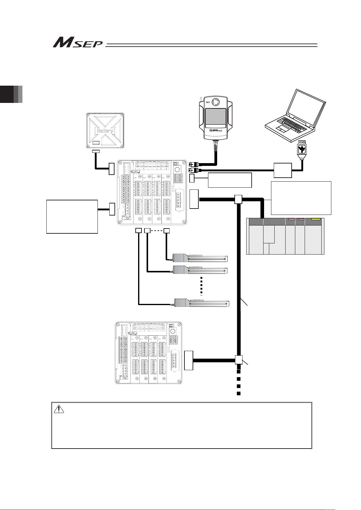
Chapter 2 Wiring
36
2.1.2 When Controlled by Fieldbus
Caution: Make sure to turn the power to the controller OFF when inserting or removing the
connector that connects the PC software or teaching pendant to the controller.
(For touch panel teaching (CON-PTA), insertion and removal of the active line is
available.)
Inserting or removing the connector while the power is turned ON causes a
controller failure.
Teaching Pendant
Touch Panel Teaching
(to be purchased separately)
Host System (Master Unit)
(PLC, etc.…Please prepare separately)
Communication power
supply (if necessary)
(24V DC
…Please prepare
separately)
A
ctuator
Emergency Stop
Circuit
Control/Drive Power
Supply
(24V DC
…Please prepare
separately)
PC software
(to be purchased separately)
A
bsolute Battery Box
Each Fieldbus
communication cable
Follow the specifications of
each Fieldbus for how to
lay out wiring.
CB-MSEP
-AB005
Page 45

Chapter 2 Wiring
37
2.1.3 For RC Gateway Control
This product is capable for the connection to RC Gateway Function (Fieldbus type) equipped in
XSEL controller to make an operation in harmony with XSEL controller.
XSEL-P/Q
MSEP
24V DC Power Supply
When RC controller
is connected additionally
PCON-DV
ACON-DV
Junction Unit for DeviceNet
Page 46

Chapter 2 Wiring
38
2.2 Operation Pattern Selected
2.2.1 Outline for Operation Patterns
PIO type MSEP units provide 6 varying patterns of PIO operation. Fieldbus type MSEP units
provide 6 varying modes of fieldbus operation. Select an appropriate pattern or fieldbus mode
based upon your application requirements. See Section 3 Operation for the details of the
operation patterns.
Interface Operation Pattern Number of position points Description Details
Single
Solenoid
System
Control is performed with one input signal as it is done
for the single solenoid.
0 : Point-to-Point
Movement
2
(Forward end,
Backward
end)
Double
Solenoid
System
Control is performed with two input signals as it is
done for the double solenoid.
Single
Solenoid
System
Speed is available to change during a movement.
Control is performed with one input signal as it is done
for Single Solenoid, however, the speed can be
changed while in move if a movement speed change
signal is input.
1 : Point-to-Point
Movement,
Movement Speed
Setting
2
(Forward end,
Backward
end)
Double
Solenoid
System
Speed is available to change during a movement.
Control is performed with two input signals as it is
done for Double Solenoid, however, the speed can be
changed while in move if a movement speed change
signal is input.
Single
Solenoid
System
Control is performed with one input signal as it is done
for Single Solenoid, however, the target position and
operational condition can be changed while in move if
a target position change signal is input.
2 : Point-to-Point
Movement, Target
Position Change
2
(Forward end,
Backward
end)
Double
Solenoid
System
Control is performed with two input signals as it is
done for Double Solenoid, however, the target position
and operational condition can be changed while in
move if a target position change signal is input.
3 : 2-Input, 3-Point
Movement
3
(Forward end, Backward
end, Intermediate)
Movement is made among three points with the
combination of two input signals.
4 : 3-Input, 3-Point
Movement
3
(Forward end, Backward
end, Intermediate)
Movement is made among three points with three
input signals.
PIO
Type
5 : Continuous
Reciprocating
Operation
2
(Forward end, Backward
end)
Movement is made between the forward end and
backward end repeatedly while one input signal is ON.
3.1.1 (1)
0 to 5 SEP I/O 2 or 3 The same control as PIO stated previously is available
if the interface is Fieldbus.
Positioner 1 256 The position data can be registered at 256 points at
the maximum and a stop can be made at the
registered points. Monitoring of the current position is
also available.
Simple
Direct
The target position can be indicated directly with
inputting a number. Monitoring of the current position
is also available.
Number of
direct
numerical
specification
The target position, speed acceleration/deceleration
and pressing current limit can be indicated with
inputting a number. Monitoring of not only the current
position, but also the current speed and indicated
current are available.
Positioner 2 256 The position data can be registered at 256 points at
the maximum and a stop can be made at the
registered points. The monitoring of the current
position is not available.
This mode is that the transferred data is reduced from
Positioner 1 Mode.
Fieldbus
Type
6
Positioner 3 256 The position data can be registered at 256 points at
the maximum and a stop can be made at the
registered points. The monitoring of the current
position is not available.
This mode is that the transferred data is reduced from
Positioner 2 Mode to control only the minimum signals
necessary only for the movement operation.
3.1.1 (2)
Page 47

Chapter 2 Wiring
39
2.2.2 PIO Pattern Selection and PIO Signal
1) PIO Patterns and Signal Assignment
The signal assignment of I/O flat cable by the PIO pattern is as shown below. Follow the
following table to connect the external equipment (such as PLC).
Operation Pattern (PIO pattern)
0 1 2 3 4 5
Category
PIO
Functions
Point-to-Point
Movement
Movement speed
setting
Target position
change
2-Input,
3-Point
Movement
3-Input,
3-Point
Movement
Continuous
reciprocating
operation
Fieldbus
connection
Number of
positioning
points
2 points 2 points 2 points 3 points
3 points 2 points
Home return
signal
× (Home-return operation at the power-on or the first movement operation)
Servo ON
signal
ż (Automatic servo-on is also available at the power-on)
Movement
speed
setting
× ż × × × ż
Input
Target
position
change
× × ż × × ×
Servo ON
signal
ż (Selection available in the initial setting whether to use)
Homing
completion
signal
ż (Selection available in the initial setting whether to
use)
×
ż (Selection available in
the initial setting
whether to use)
Output
Zone signal,
Position
zone sig
× × × × × ×
Pin
No.
Solenoid
system
Single Double Single Double Single Double
– Double –
A1 – COM 24V
A2 IN0 ST0 ST0 ST0 ST0 ST0 ST0 ST0 ST0 ASTR
A3 IN1 *STP
ST1
(Note 1)
*STP
ST1
(Note 1)
*STP
ST1
(Note 1)
ST1
(Note 1)
ST1
(Note 1)
*STP
A4 IN2 RES SPDC(RES)
(Note 2)
CN1(RES)
(Note 2)
RES
ST2(RES)
(Note 2)
RES
A5
Input
(Axis
No.0)
IN3 –/SON –/SON –/SON –/SON –/SON –/SON
A6 IN0 ST0 ST0 ST0 ST0 ST0 ST0 ST0 ST0 ASTR
A7 IN1 *STP
ST1
(Note 1)
*STP
ST1
(Note 1)
*STP
ST1
(Note 1)
ST1
(Note 1)
ST1
(Note 1)
*STP
A8 IN2 RES SPDC(RES)
(Note 2)
CN1(RES)
(Note 2)
RES
ST2(RES)
(Note 2)
RES
A9
Input
(Axis
No.1)
IN3 –/SON –/SON –/SON –/SON –/SON –/SON
A10 IN0 ST0 ST0 ST0 ST0 ST0 ST0 ST0 ST0 ASTR
A11 IN1 *STP
ST1
(Note 1)
*STP
ST1
(Note 1)
*STP
ST1
(Note 1)
ST1
(Note 1)
ST1
(Note 1)
*STP
A12 IN2 RES SPDC(RES)
(Note 2)
CN1(RES)
(Note 2)
RES
ST2(RES)
(Note 2)
RES
A13
Input
(Axis
No.2)
IN3 –/SON –/SON –/SON –/SON –/SON –/SON
A14 IN0 ST0 ST0 ST0 ST0 ST0 ST0 ST0 ST0 ASTR
A15 IN1 *STP
ST1
(Note 1)
*STP
ST1
(Note 1)
*STP
ST1
(Note 1)
ST1
(Note 1)
ST1
(Note 1)
*STP
A16 IN2 RES SPDC(RES)
(Note 2)
CN1(RES)
(Note 2)
RES
ST2(RES)
(Note 2)
RES
A17
Input
(Axis
No.3)
IN3 –/SON –/SON –/SON –/SON –/SON –/SON
A18 OUT0 LS0/PE0 LS0/PE0 LS0/PE0 LS0/PE0 LS0/PE0 LS0/PE0
A19 OUT1 LS1/PE1 LS1/PE1 LS1/PE1 LS1/PE1 LS1/PE1 LS1/PE1
A20 OUT2 HEND/SV HEND/SV HEND/SV LS2/PE2 LS2/PE2 HEND/SV
A21
Output
(Axis
No.0)
OUT3 *ALM/SV *ALM/SV *ALM/SV *ALM/SV *ALM/SV *ALM/SV
A22 OUT0 LS0/PE0 LS0/PE0 LS0/PE0 LS0/PE0 LS0/PE0 LS0/PE0
A23 OUT1 LS1/PE1 LS1/PE1 LS1/PE1 LS1/PE1 LS1/PE1 LS1/PE1
A24 OUT2 HEND/SV HEND/SV HEND/SV HEND/SV LS2/PE2 LS2/PE2
A25
Output
(Axis
No.1)
OUT3 *ALM/SV *ALM/SV *ALM/SV *ALM/SV *ALM/SV *ALM/SV
A26 OUT0 LS0/PE0 LS0/PE0 LS0/PE0 LS0/PE0 LS0/PE0 LS0/PE0
A27 OUT1 LS1/PE1 LS1/PE1 LS1/PE1 LS1/PE1 LS1/PE1 LS1/PE1
A28 OUT2 HEND/SV HEND/SV HEND/SV HEND/SV LS2/PE2 LS2/PE2
A29
Output
(Axis
No.2)
OUT3 *ALM/SV *ALM/SV *ALM/SV *ALM/SV *ALM/SV *ALM/SV
A30 OUT0 LS0/PE0 LS0/PE0 LS0/PE0 LS0/PE0 LS0/PE0 LS0/PE0
A31 OUT1 LS1/PE1 LS1/PE1 LS1/PE1 LS1/PE1 LS1/PE1 LS1/PE1
A32 OUT2 HEND/SV HEND/SV HEND/SV HEND/SV LS2/PE2 LS2/PE2
A33
Output
(Axis
No.3)
OUT3 *ALM/SV *ALM/SV *ALM/SV *ALM/SV *ALM/SV *ALM/SV
Refer to 3.4
Fieldbus
Type
Address
Map
A34 – COM 0V
(Note) “*” in codes above shows the signal of the active low.
Note 1 It is invalid before home-return operation.
Note 2 The description in the brackets shows the condition before the home return operation.
Page 48

Chapter 2 Wiring
40
Operation Pattern
0 1 2 3 4 5 6
Category
PIO
Functions
Point-to-Point
Movement
Movement speed
setting
Target position
change
2-Input,
3-Point
Movement
3-Input,
3-Point
Movement
Continuous
reciprocating
operation
Fieldbus
connection
Pin
No.
Solenoid
system
Single Double Single Double Single Double – Double –
B1 – COM 24V
B2 IN0 ST0
ST0
ST0 ST0 ST0 ST0 ST0 ST0 ASTR
B3 IN1 *STP
ST1
(Note 1)
*STP
ST1
(Note 1)
*STP
ST1
(Note 1)
ST1
(Note 1)
ST1
(Note 1)
*STP
B4 IN2 RES
SPDC(RES)
(Note 2)
CN1(RES)
(Note 2)
RES
ST2(RES)
(Note 2)
RES
B5
Input
(Axis
No.4)
IN3 –/SON –/SON –/SON –/SON –/SON –/SON
B6 IN0 ST0 ST0 ST0 ST0 ST0 ST0 ST0 ST0 ASTR
B7 IN1 *STP
ST1
(Note 1)
*STP
ST1
(Note 1)
*STP
ST1
(Note 1)
ST1
(Note 1)
ST1
(Note 1)
*STP
B8 IN2 RES
SPDC(RES)
(Note 2)
CN1(RES)
(Note 2)
RES
ST2(RES)
(Note 2)
RES
B9
Input
(Axis
No.5)
IN3 –/SON –/SON –/SON –/SON –/SON –/SON
B10 IN0 ST0 ST0 ST0 ST0 ST0 ST0 ST0 ST0 ASTR
B11 IN1 *STP
ST1
(Note 1)
*STP
ST1
(Note 1)
*STP
ST1
(Note 1)
ST1
(Note 1)
ST1
(Note 1)
*STP
B12 IN2 RES
SPDC(RES)
(Note 2)
CN1(RES)
(Note 2)
RES
ST2(RES)
(Note 2)
RES
B13
Input
(Axis
No.6)
IN3 –/SON –/SON –/SON –/SON –/SON –/SON
B14 IN0 ST0 ST0 ST0 ST0 ST0 ST0 ST0 ST0 ASTR
B15 IN1 *STP
ST1
(Note 1)
*STP
ST1
(Note 1)
*STP
ST1
(Note 1)
ST1
(Note 1)
ST1
(Note 1)
*STP
B16 IN2 RES
SPDC(RES)
(Note 2)
CN1(RES)
(Note 2)
RES
ST2(RES)
(Note 2)
RES
B17
Input
(Axis
No.7)
IN3 –/SON –/SON –/SON –/SON –/SON –/SON
B18 OUT0 LS0/PE0 LS0/PE0 LS0/PE0 LS0/PE0 LS0/PE0 LS0/PE0
B19 OUT1 LS1/PE1 LS1/PE1 LS1/PE1 LS1/PE1 LS1/PE1 LS1/PE1
B20 OUT2 HEND/SV HEND/SV HEND/SV HEND/SV LS2/PE2 LS2/PE2
B21
Output
(Axis
No.4)
OUT3 *ALM/SV *ALM/SV *ALM/SV *ALM/SV *ALM/SV *ALM/SV
B22 OUT0 LS0/PE0 LS0/PE0 LS0/PE0 LS0/PE0 LS0/PE0 LS0/PE0
B23 OUT1 LS1/PE1 LS1/PE1 LS1/PE1 LS1/PE1 LS1/PE1 LS1/PE1
B24 OUT2 HEND/SV HEND/SV HEND/SV HEND/SV LS2/PE2 LS2/PE2
B25
Output
(Axis
No.5)
OUT3 *ALM/SV *ALM/SV *ALM/SV *ALM/SV *ALM/SV *ALM/SV
B26 OUT0 LS0/PE0 LS0/PE0 LS0/PE0 LS0/PE0 LS0/PE0 LS0/PE0
B27 OUT1 LS1/PE1 LS1/PE1 LS1/PE1 LS1/PE1 LS1/PE1 LS1/PE1
B28 OUT2 HEND/SV HEND/SV HEND/SV HEND/SV LS2/PE2 LS2/PE2
B29
Output
(Axis
No.6)
OUT3 *ALM/SV *ALM/SV *ALM/SV *ALM/SV *ALM/SV *ALM/SV
B30 OUT0 LS0/PE0 LS0/PE0 LS0/PE0 LS0/PE0 LS0/PE0 LS0/PE0
B31 OUT1 LS1/PE1 LS1/PE1 LS1/PE1 LS1/PE1 LS1/PE1 LS1/PE1
B32 OUT2 HEND/SV HEND/SV HEND/SV HEND/SV LS2/PE2 LS2/PE2
B33
Output
(Axis
No.7)
OUT3 *ALM/SV *ALM/SV *ALM/SV *ALM/SV *ALM/SV *ALM/SV
Refer to 3.4
Fieldbus
Type
Address
Map
B34 – COM 0V
(Note) Change the output and class considering the initial setting.
[Refer to [Step 5] in 3.2 Initial Setting for the settings, and 3.8.2 Fieldbus SEP I/O Mode and PIO Operation for the
details of the signals.]
Note 1 It is invalid before home-return operation.
Note 2 The description in the brackets shows the condition before the home return operation.
(Reference) Signal of Active Low
Signal with “*” expresses the signal of active low. A signal of active low is a signal that the input
signal is processed when it is turned OFF, output signal is ordinary on while the power is ON, and
turns OFF when the signal is output.
Page 49

Chapter 2 Wiring
41
2) List of PIO Signals
The table below lists the functions of PIO signals. Refer to the section shown in Relevant
Sections for the details of the control of each signal.
Category
Signal
Abbreviation
Signal Name Function Description
Relevant
Sections
ST0
• Moving Signal
(Single Solenoid
System)
• Backward End
Movement Signal
(Double Solenoid
System)
• Move Signal 1
(PIO Pattern 3)
ST1
• Forward End
Movement Signal
• Move Signal 2
(PIO Pattern 3)
ST2
• Intermediate Point
Movement Signal
The positioning to the corresponding target position is
performed, when the signal leading edge created in the
mode change from OFF to ON, or ON level is detected.
3.8.2
[4] [5]
*STP Pause
When this signal is turned OFF while in move, the
actuator decelerates and then stops. The remaining
movement is in a hold while the actuator is stopped and
will resume when the signal turns back ON.
3.8.2 [3]
RES Reset
An alarm will be reset when this signal is turned ON.
(Note) Depending on the alarm level, alarm reset might
not be available. Refer to the Trouble Shooting for
the details.
3.8.2 [3]
SON Servo ON
The servo remains ON while this signal is ON, or OFF
while this signal is OFF.
3.8.2 [1]
SPDC
Movement Speed
Change
To change the speed during a movement operation, input
the movement signal while this signal is ON.
(Note) This signal is available only in the operation
pattern 1.
3.8.2 [10]
CN1 Target Position Change
Turn this signal ON when an operation is made with a
change to the operation condition.
When this signal is turned ON or OFF during the
operation, the position data is changed.
(Note) This signal is available only in the operation
pattern 2.
3.8.2 [11]
Input
ASTR
Continuous
Reciprocating Operation
A back and forth movement is performed repeatedly
between the forward end and the backward end while this
signal is ON. When this signal is turned OFF during the
movement operation, after the actuator is positioned to
the current target, it is stopped.
(Note) This signal is available only in the operation
pattern 5.
3.8.2 [13]
LS0
Backward End Position
Detection
LS1
Forward End Position
Detection
LS2
Intermediate Point
Detection
The same operation as of the limit switch of the air
cylinder is performed.
It is turned ON when the current position is within the
positioning width for each position detection output.
3.8.2 [5]
PE0
Backward End Point
Positioning Completion
PE1
Forward End Point
Positioning Completion
PE2
Intermediate Point
Positioning Completion
This signal is turned ON when the current position goes
within the positioning width, and the positioning to the
target position is complete.
It is turned OFF in the Servo-Motor OFF mode or the
Emergency Stop Mode.
3.8.2 [4]
HEND
Home Return
Completion
This signal will turn ON when home return has been
completed.
It will be kept ON unless the home position is lost.
3.8.2 [6]
SV Servo ON This signal will remain ON while the servo is ON. 3.8.2 [1]
Output
*ALM Alarm Output
This signal remains ON in normal conditions of use and
turns OFF when an alarm is generated.
3.8.2 [2]
Signal with “*” expresses the signal of active low. In the controller, the process is held when the input signal is turned OFF.
Page 50

Chapter 2 Wiring
42
2.3 Circuit Diagram
Sample circuit diagrams are shown below.
[1] Power Supply and Emergency Stop
The diagram shown below is an example of a circuit for when reflecting the emergency stop
switch on a teaching pendant to the emergency stop circuit of the system.
Note 1 When the teaching pendant is not connected, S1 and S2 become short-circuited inside the controller.
Note 2 When the motor power must be disconnected externally for safety category compliance, apply a safety rated
contactor between MPISLOT* and MPOSLOT*. Choose one that is capable to open and close with the motor
current consumption of the connected actuator [Refer to 1.2 List of Basic Specifications.].
Note 3 The rating for the emergency stop signal (EMG-) to turn ON/OFF at contact CR1 is 24V DC and 10mA.
Note 4 For CR1, select the one with coil current 0.1A or less.
Note 5 If supplying power with using a 24V DC, having it turned ON/OFF, keep the 0V connected and have the +24V
supplied/cut (cut one side only).
Note 6 By cutting out the connection between EMG+SLOT* and EMGINSLOT*, only the disconnected slot number can be
made in the condition of an emergency stop. (*: Slot Number)
EMGINSLOT0
EMGINSLOT1
EMGINSLOT2
EMGINSLOT3
Emergency Stop
Reset Switch
Emergency Stop
Switch
CR1
SIO Connector
CR1
24V
0V
Emergency Stop Control Circuit
Motor Power Supply (Slot 3)
(Axis No.6 and 7)
MPISLOT3
MPOSLOT3
CR2
(Note2)
MPISLOT2
MPOSLOT2
CR2
(Note2
)
MPOSLOT1
MPISLOT1
CR2
(Note2)
MPISLOT0
MPOSLOT0
CR2
(Note2)
Motor Power Supply (Slot 2)
(Axis No.4 and 5)
Motor Power Supply (Slot 1)
(Axis No.2 and 3)
Motor Power Supply (Slot 0)
(Axis No.0 and 1)
MP+24V
0V
CP+24V 0V
Control
Powe
r
External Drive Cutoff •
Emergency Stop Input Connector
Power Line Input Connecto
r
EMG+SLOT0
(Note6
)
S1
4
3
2
1
12
11
10
9
7
8
5
6
15
16
13
14
1
3
4
2
Emergency Stop Switch on
Teaching Pendant
S2
(Note1)
EMG A EMG B
MSEP
85
EMG-
EMG+SLOT1
(Note6
)
EMG+SLOT2
(Note6
)
EMG+SLOT3
(Note6
)
3
2
4
CR1
(Note4
)
CR2
(Note2
)
CR1
System I/O Connector
Page 51

Chapter 2 Wiring
43
Check the previous page for Notes 1 to 6.
EMGINSLOT0
EMGINSLOT1
EMGINSLOT2
EMGINSLOT3
Emergency Stop
Reset Switch
Emergency Stop
Switch
CR1
SIO Connector
CR1
24V 0V
S1
Emergency Stop Control Circuit
Motor Power Supply (Slot 3)
(Axis No.6 and 7)
MPISLOT3
MPOSLOT3
CR2
(Note2)
MPISLOT2
MPOSLOT2
CR2
(Note2)
MPOSLOT1
MPISLOT1
CR2
(Note2)
MPISLOT0
MPOSLOT0
CR2
(Note2)
Motor Power Supply (Slot 2)
(Axis No.4 and 5)
Motor Power Supply (Slot 1)
(Axis No.2 and 3)
Motor Power Supply (Slot 0)
(Axis No.0 and 1)
MP+24V 0V
CP+24V 0V
Control
Powe
r
External Drive Cutoff •
Emergency Stop Input Connector
Power Line Input Connecto
r
System I/O Connector
MSEP
MPISLOT3
MPOSLOT3
CR2
(Note 2)
MPISLOT2
MPOSLOT2
CR2
(Note 2)
MPOSLOT1
MPISLOT1
CR2
(Note 2)
MPISLOT0
MPOSLOT0
CR2
(Note 2)
MP+24V 0V
CP+24V 0V
EMG+SLOT0
(Note6
)
EMG+SLOT0
EMGINSLOT0
EMG+SLOT1
EMGINSLOT1
EMG+SLOT2
EMGINSLOT2
EMG+SLOT3
EMGINSLOT3
S1
4
3
2
1
12
11
10
9
7
8
5
6
15
16
13
14
1
3
4
2
3
4
3
2
1
12
11
10
9
7
8
5
6
15
16
13
14
1
3
4
2
External Drive Cutoff • Emergency Stop Input Connecto
r
Power Line Input Connecto
r
Emergency Stop Switch on
Teaching Pendant
(Note6
)
S2
(Note1)
EMG A EMG B
MSEP
85
EMG-
EMG+SLOT2
(Note6
)
EMG+SLOT3
(Note6
)
3
2
4
SIO Connector
S2
EMG-
2
4
85
(Note1)
(Note6
)
(Note6
)
(Note6
)
CR1
(Note4
)
CR2
(Note2
)
CR1
System I/O Connector
EMG+SLOT1
(Note6
)
Page 52

Chapter 2 Wiring
44
Motor • Encoder Circuit
There is an axis number (AX0 to AX7) shown on the actuator cables. Refer to the figure below to
plug the actuators correctly.
Wrong connection will issue an error such as the encoder wire breakage.
Check in the instruction manual of each actuator for the details (connection layout diagram) of
each cable.
1) Connection to RCP2 Series
2) Connection to RCP3, RCP4, RCA2 and RCL Series
3) Connection to RCP2 Small Rotary Series
MSEP
AX0 to 7
Actuator
Connector
Connection
Cable
(Note 1)
MSEP
AX0 to 7
Actuator
Connector
Connection
Cable
(Note 1)
MSEP
AX0 to 7
Actuator
Connector
Connection
Cable
(Note 1)
AX0
(1st axis)
AX1
(2nd axis)
AX2
(3rd axis)
AX3
(4th axis)
AX4
(5th axis)
AX5
(6th axis)
AX6
(7th axis)
AX7
(8th axis)
Page 53

Chapter 2 Wiring
45
4) Connection to RCA Series
Note 1 Applicable Connection Cable Model Codes ƑƑƑ: Cable length Example) 030 = 3m
Model Cable Remarks
RCP2
(Except for small rotary)
CB-PSEP-MPAƑƑƑ Robot cable from 0.5 to 20m
Small rotary type
RCP2-RTBL/RTCL
/RTBSL/RTCSL
/RTBBL/RTCBL
CB-RPSEP-MAƑƑƑ Robot cable from 0.5 to 20m
RCA CB-ASEP-MPAƑƑƑ Robot cable from 0.5 to 20m
RCP3, RCA2, RCL CB-APSEP-MPAƑƑƑ Robot cable from 0.5 to 20m
RCP3, RCA2, RCL CB-APSEP-MPAƑƑƑ-LC Standard cable from 0.5 to 20m
RCP4 CB-CA-MPAƑƑƑ-RB Robot cable from 0.5 to 20m
RCP4 CB-CA-MPAƑƑƑ Standard cable from 0.5 to 20m
[2] Connection to Absolute Battery Unit (for Simple Absolute Type Only)
(Note) Do not apply force not being perpendicular to the connector when insert or detach the
cable.
[3] Layout for Mode Switchover (AUTO/MANU) Circuit
When a switchover of the operation modes (AUTO/MANU) is required with an external input,
connect a device such as a switch between AUTO/MANU + terminal and AUTO/MANU –
terminal.
If not switching externally, apply a jumper on AUTO/MANU + terminal and AUTO/MANU –
terminal.
MSEP
AX0 to 7
Actuator
Connector
Connection
Cable
(Note 1)
MSEP
A
bsolute Battery
Connector
Absolute Battery
Box
CB-MSEP-AB005
The cable length should
be 0.5m.
MSEP
A
UTO/MANU-
A
UTO/MANU+
System I/O Connector
Operation Mode Setting
(AUTO/MANU) Switch
MANU
20K:
A
UTO
100K:
24V
External
Operation Mode
Setting
(AUTO/MANU)
Switch
5.6K:
OFF: AUTO
ON : MANU
Internal
Power
Supply
5
6
Page 54

Chapter 2 Wiring
46
[4] Layout for External Brake Input Circuit
Lay out the circuit when an external compulsory brake release with using an actuator equipped
with a brake is desired. It is not necessary if an external release is not required.
It is possible to release the brake as long as the control power is supplied to MSEP even without
the main power being supplied to the controller.
[5] Layout of Regenerative Resistor (Option)
Condition to Require Regenerative Units
Number of Connected Actuator 3 to 8 units of high acceleration/deceleration type
actuators
Number of Regenerative Unit 1
Caution: The regenerative resistor consumes regenerative current and converts it to heat.
Therefore, the temperature may get high in some operational conditions.
Attach on the metal part of the device with a screw to radiate the heat.
A
xis No.0 Brake Release Input Circuit
A
xis No.7 Brake Release Input Circuit
A
xis No.6 Brake Release Input Circuit
A
xis No.4 Brake Release Input Circuit
A
xis No.5 Brake Release Input Circuit
A
xis No.3 Brake Release Input Circuit
A
xis No.2 Brake Release Input Circuit
A
xis No.1 Brake Release Input Circuit
MSEP
GND for Brake Release
BKRLS AXIS No.3
BKRLS AXIS No.0
BKRLS AXIS No.2
0V
0V
BKRLS AXIS No.5
BKRLS AXIS No.1
BKRLS AXIS No.4
BKRLS AXIS No.7
BKRLS AXIS No.6
24V
0V
External Brake Input Connector
MSEP
RB-
RB+
System I/O
Connector
External Regenerative
Resistor Units
(
RER-1
)
4
3
2
1
9
8
7
6
5
10
7
8
Page 55
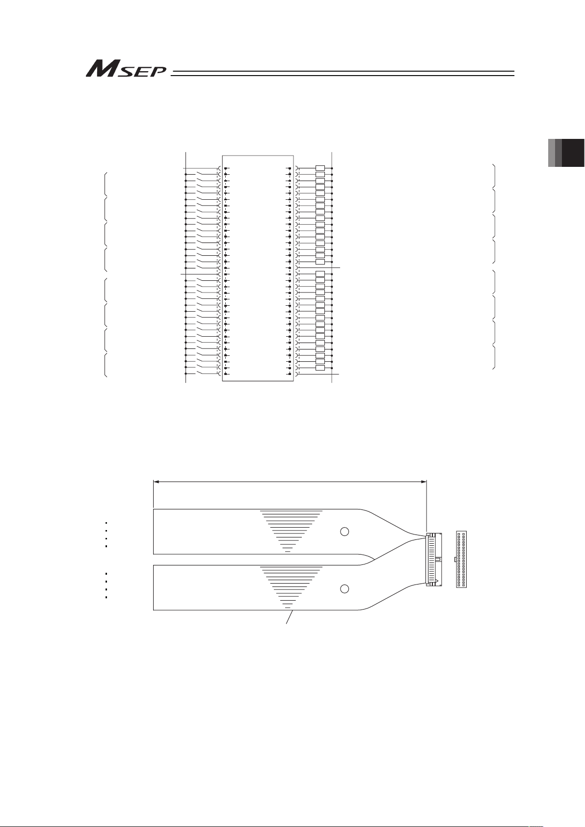
Chapter 2 Wiring
47
[6] Wiring Layout for PIO (lay out the circuit for PIO type)
Ɣ Operation pattern 0 ······Point-to-Point Movement (Standard)
A1
0V (NPN Type)
24V DC (PNP Type)
24V DC (NPN Type)
0V (PNP Type)
24V Supply (for I/O)
Movement/Backward End Movement
Pause/Forward End Movement
Reset
No function/Servo ON
Movement/Backward End Movement
Pause/Forward End Movement
Reset
No function/Servo ON
Movement/Backward End Movement
Pause/Forward End Movement
Reset
No function/Servo ON
Movement/Backward End Movement
Pause/Forward End Movement
Reset
No function/Servo ON
Backward End Position Detection/Backward End Point Positioning Completion
Forward End Position Detection/Forward End Point Positioning Completion
Home Return Completion/Servo ON
Alarm Output/Servo ON
Backward End Position Detection/Backward End Point Positioning Completion
Forward End Position Detection/Forward End Point Positioning Completion
Home Return Completion/Servo ON
Alarm Output/Servo ON
Backward End Position Detection/Backward End Point Positioning Completion
Forward End Position Detection/Forward End Point Positioning Completion
Home Return Completion/Servo ON
Alarm Output/Servo ON
Backward End Position Detection/Backward End Point Positioning Completion
Forward End Position Detection/Forward End Point Positioning Completion
Home Return Completion/Servo ON
Alarm Output/Servo ON
0V Supply (for I/O)
Backward End Position Detection/Backward End Point Positioning Completion
Forward End Position Detection/Forward End Point Positioning Completion
Home Return Completion/Servo ON
Alarm Output/Servo ON
Backward End Position Detection/Backward End Point Positioning Completion
Forward End Position Detection/Forward End Point Positioning Completion
Home Return Completion/Servo ON
Alarm Output/Servo ON
Backward End Position Detection/Backward End Point Positioning Completion
Forward End Position Detection/Forward End Point Positioning Completion
Home Return Completion/Servo ON
Alarm Output/Servo ON
Backward End Position Detection/Backward End Point Positioning Completion
Forward End Position Detection/Forward End Point Positioning Completion
Home Return Completion/Servo ON
Alarm Output/Servo ON
0V Supply (for I/O)
A18
MSEP
24V
ST0
*STP/ST1
RES
-/SON
ST0
*STP/ST1
RES
-/SON
ST0
*STP/ST1
RES
-/SON
ST0
*STP/ST1
RES
-/SON
24V
ST0
*STP/ST1
RES
-/SON
ST0
*STP/ST1
RES
-/SON
ST0
*STP/ST1
RES
-/SON
ST0
*STP/ST1
RES
-/SON
PIO Connector
A2
A3
A4
A5
A6
A7
A8
A9
A10
A11
A12
A13
A14
A15
A16
A17
B2
B1
B3
B4
B5
B6
B7
B8
B9
B10
B11
B12
B13
B14
B15
B16
B17
A19
A20
A21
A22
A23
A24
A25
A26
A27
A28
A29
A30
A31
A32
A33
B18
B19
B20
B21
B22
B23
B24
B25
B26
B27
B28
B29
B30
B31
B32
B33
B34
A34
A
xis No.0
A
xis No.1
A
xis No.2
A
xis No.3
A
xis No.4
A
xis No.5
A
xis No.6
A
xis No.7
Axis No.0
Axis No.1
Axis No.2
Axis No.3
Axis No.4
Axis No.5
Axis No.6
Axis No.7
LS0/PE0
LS1/PE1
HEND/SV
*ALM/SV
LS0/PE0
LS1/PE1
HEND/SV
*ALM/SV
LS0/PE0
LS1/PE1
HEND/SV
*ALM/SV
LS0/PE0
LS1/PE1
HEND/SV
*ALM/SV
0V
LS0/PE0
LS1/PE1
HEND/SV
*ALM/SV
LS0/PE0
LS1/PE1
HEND/SV
*ALM/SV
LS0/PE0
LS1/PE1
HEND/SV
*ALM/SV
LS0/PE0
LS1/PE1
HEND/SV
*ALM/SV
0V
“*” in codes above shows the signal of the active low. Processing occurs when an input signal
of the type is turned OFF. An output signal of the type is normally ON in the power-on status
and turned OFF at signal output.
Use the attached cable for the I/O connection.
Model : CB-MSEP-PIOƑƑƑ (ƑƑƑ indicates the cable length L. Example. 020 = 2m)
Flat Cable (34-core) × 2
YW-8 (34B)
BR-5 (1B)
YW-4 (34A)
BR-1 (1A)
34A 34B
1A 1B
Half Pitch MIL Socket
HIF6-68D-1.27R (Hirose Electric)
A
B
L
No treatment
conducted
No treatment
conducted
Page 56

Chapter 2 Wiring
48
Ɣ Operation pattern 1 ······Point-to-Point Movement (Moving Speed Setting)
A1
0V (NPN Type)
24V DC (PNP Type)
24V DC (NPN Type)
0V (PNP Type)
24V Supply (for I/O)
Movement/Backward End Movement
Pause/Forward End Movement
Movement Speed Change/Reset
No function
/Servo ON
Movement/Backward End Movement
Pause/Forward End Movement
Movement Speed Change/Reset
No function
/Servo ON
Movement/Backward End Movement
Pause/Forward End Movement
Movement Speed Change/Reset
No function
/Servo ON
Movement/Backward End Movement
Pause/Forward End Movement
Movement Speed Change/Reset
No function
/Servo ON
Backward End Position Detection/Backward End Point Positioning Completion
Forward End Position Detection/Forward End Point Positioning Completion
Home Return Completion/Servo ON
Alarm Output/Servo ON
Backward End Position Detection/Backward End Point Positioning Completion
Forward End Position Detection/Forward End Point Positioning Completion
Home Return Completion/Servo ON
Alarm Output/Servo ON
Backward End Position Detection/Backward End Point Positioning Completion
Forward End Position Detection/Forward End Point Positioning Completion
Home Return Completion/Servo ON
Alarm Output/Servo ON
Backward End Position Detection/Backward End Point Positioning Completion
Forward End Position Detection/Forward End Point Positioning Completion
Home Return Completion/Servo ON
Alarm Output/Servo ON
0V Supply (for I/O)
Backward End Position Detection/Backward End Point Positioning Completion
Forward End Position Detection/Forward End Point Positioning Completion
Home Return Completion/Servo ON
Alarm Output/Servo ON
Backward End Position Detection/Backward End Point Positioning Completion
Forward End Position Detection/Forward End Point Positioning Completion
Home Return Completion/Servo ON
Alarm Output/Servo ON
Backward End Position Detection/Backward End Point Positioning Completion
Forward End Position Detection/Forward End Point Positioning Completion
Home Return Completion/Servo ON
Alarm Output/Servo ON
Backward End Position Detection/Backward End Point Positioning Completion
Forward End Position Detection/Forward End Point Positioning Completion
Home Return Completion/Servo ON
Alarm Output/Servo ON
0V Supply (for I/O)
A18
MSEP
24V
ST0
*STP/ST1
SPDC(RES)
-/SON
ST0
*STP/ST1
SPDC(RES)
-/SON
ST0
*STP/ST1
SPDC(RES)
-/SON
ST0
*STP/ST1
SPDC(RES)
-/SON
24V
ST0
*STP/ST1
SPDC(RES)
-/SON
ST0
*STP/ST1
SPDC(RES)
-/SON
ST0
*STP/ST1
SPDC(RES)
-/SON
ST0
*STP/ST1
SPDC(RES)
-/SON
PIO Connector
A2
A3
A4
A5
A6
A7
A8
A9
A10
A11
A12
A13
A14
A15
A16
A17
B2
B1
B3
B4
B5
B6
B7
B8
B9
B10
B11
B12
B13
B14
B15
B16
B17
A19
A20
A21
A22
A23
A24
A25
A26
A27
A28
A29
A30
A31
A32
A33
B18
B19
B20
B21
B22
B23
B24
B25
B26
B27
B28
B29
B30
B31
B32
B33
B34
A34
A
xis No.0
A
xis No.1
A
xis No.2
A
xis No.3
A
xis No.4
A
xis No.5
A
xis No.6
A
xis No.7
Axis No.0
Axis No.1
Axis No.2
Axis No.3
Axis No.4
Axis No.5
Axis No.6
Axis No.7
LS0/PE0
LS1/PE1
HEND/SV
*ALM/SV
LS0/PE0
LS1/PE1
HEND/SV
*ALM/SV
LS0/PE0
LS1/PE1
HEND/SV
*ALM/SV
LS0/PE0
LS1/PE1
HEND/SV
*ALM/SV
0V
LS0/PE0
LS1/PE1
HEND/SV
*ALM/SV
LS0/PE0
LS1/PE1
HEND/SV
*ALM/SV
LS0/PE0
LS1/PE1
HEND/SV
*ALM/SV
LS0/PE0
LS1/PE1
HEND/SV
*ALM/SV
0V
“*” in codes above shows the signal of the active low. Processing occurs when an input signal
of the type is turned OFF. An output signal of the type is normally ON in the power-on status
and turned OFF at signal output.
Use the attached cable for the I/O connection.
Model : CB-MSEP-PIOƑƑƑ (ƑƑƑ indicates the cable length L. Example. 020 = 2m)
Flat Cable (34-core) × 2
YW-8 (34B)
BR-5 (1B)
YW-4 (34A)
BR-1 (1A)
34A 34B
1A 1B
Half Pitch MIL Socket
HIF6-68D-1.27R (Hirose Electric)
A
B
L
No treatment
conducted
No treatment
conducted
Page 57
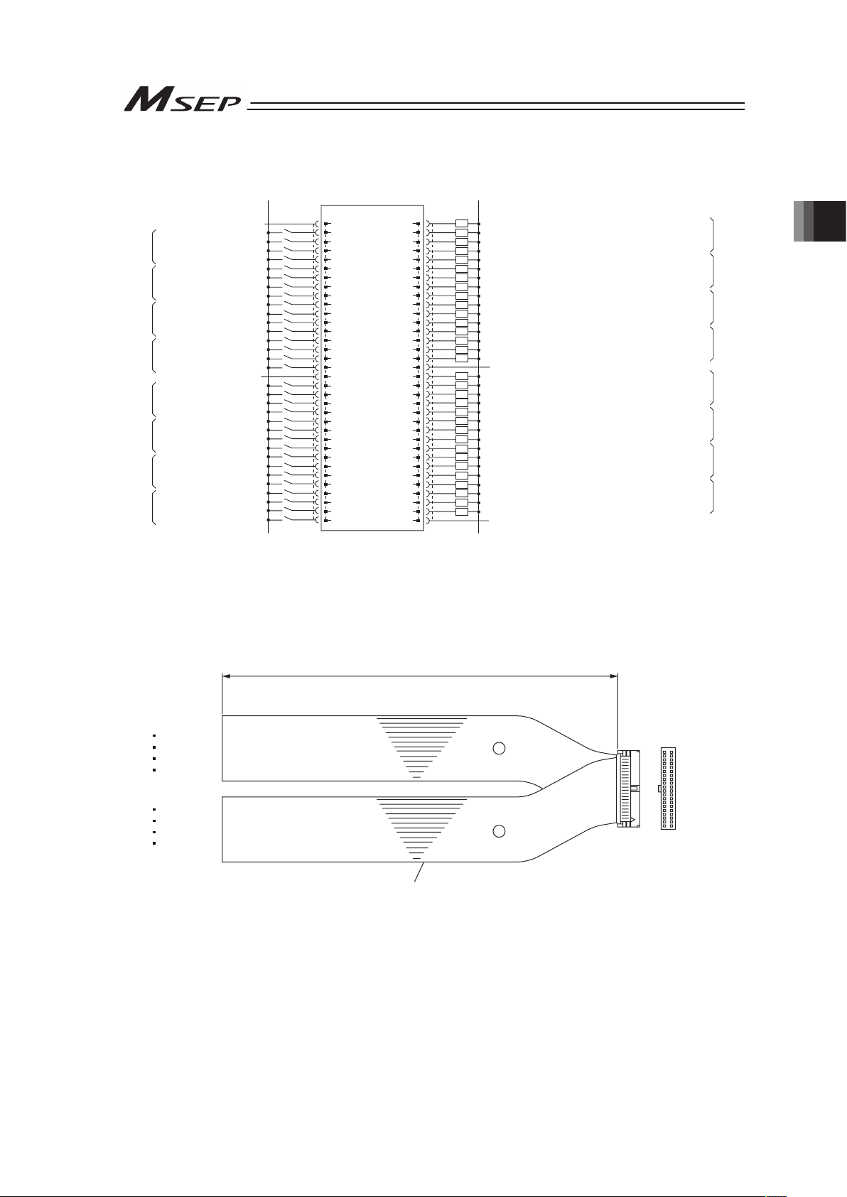
Chapter 2 Wiring
49
Ɣ Operation pattern 2 ······Point-to-Point Movement (Target Position Change)
A1
0V (NPN Type)
24V DC (PNP Type)
24V DC (NPN Type)
0V (PNP Type)
24V Supply (for I/O)
Movement/Backward End Movement
Pause/Forward End Movement
Target Position Change/Reset
No function/Servo ON
Movement/Backward End Movement
Pause/Forward End Movement
Target Position Change/Reset
No function/Servo ON
Movement/Backward End Movement
Pause/Forward End Movement
Target Position Change/Reset
No function/Servo ON
Movement/Backward End Movement
Pause/Forward End Movement
Target Position Change/Reset
No function/Servo ON
Backward End Position Detection/Backward End Point Positioning Completion
Forward End Position Detection/Forward End Point Positioning Completion
Home Return Completion/Servo ON
Alarm Output/Servo ON
Backward End Position Detection/Backward End Point Positioning Completion
Forward End Position Detection/Forward End Point Positioning Completion
Home Return Completion/Servo ON
Alarm Output/Servo ON
Backward End Position Detection/Backward End Point Positioning Completion
Forward End Position Detection/Forward End Point Positioning Completion
Home Return Completion/Servo ON
Alarm Output/Servo ON
Backward End Position Detection/Backward End Point Positioning Completion
Forward End Position Detection/Forward End Point Positioning Completion
Home Return Completion/Servo ON
Alarm Output/Servo ON
0V Supply (for I/O)
Backward End Position Detection/Backward End Point Positioning Completion
Forward End Position Detection/Forward End Point Positioning Completion
Home Return Completion/Servo ON
Alarm Output/Servo ON
Backward End Position Detection/Backward End Point Positioning Completion
Forward End Position Detection/Forward End Point Positioning Completion
Home Return Completion/Servo ON
Alarm Output/Servo ON
Backward End Position Detection/Backward End Point Positioning Completion
Forward End Position Detection/Forward End Point Positioning Completion
Home Return Completion/Servo ON
Alarm Output/Servo ON
Backward End Position Detection/Backward End Point Positioning Completion
Forward End Position Detection/Forward End Point Positioning Completion
Home Return Completion/Servo ON
Alarm Output/Servo ON
0V Supply (for I/O)
A18
MSEP
24V
ST0
*STP/ST1
CN1(RES)
-/SON
ST0
*STP/ST1
CN1(RES)
-/SON
ST0
*STP/ST1
CN1(RES)
-/SON
ST0
*STP/ST1
CN1(RES)
-/SON
24V
ST0
*STP/ST1
CN1(RES)
-/SON
ST0
*STP/ST1
CN1(RES)
-/SON
ST0
*STP/ST1
CN1(RES)
-/SON
ST0
*STP/ST1
CN1(RES)
-/SON
PIO Connector
A2
A3
A4
A5
A6
A7
A8
A9
A10
A11
A12
A13
A14
A15
A16
A17
B2
B1
B3
B4
B5
B6
B7
B8
B9
B10
B11
B12
B13
B14
B15
B16
B17
A19
A20
A21
A22
A23
A24
A25
A26
A27
A28
A29
A30
A31
A32
A33
B18
B19
B20
B21
B22
B23
B24
B25
B26
B27
B28
B29
B30
B31
B32
B33
B34
A34
A
xis No.0
A
xis No.1
A
xis No.2
A
xis No.3
A
xis No.4
A
xis No.5
A
xis No.6
A
xis No.7
Axis No.0
Axis No.1
Axis No.2
Axis No.3
Axis No.4
Axis No.5
Axis No.6
Axis No.7
LS0/PE0
LS1/PE1
HEND/SV
*ALM/SV
LS0/PE0
LS1/PE1
HEND/SV
*ALM/SV
LS0/PE0
LS1/PE1
HEND/SV
*ALM/SV
LS0/PE0
LS1/PE1
HEND/SV
*ALM/SV
0V
LS0/PE0
LS1/PE1
HEND/SV
*ALM/SV
LS0/PE0
LS1/PE1
HEND/SV
*ALM/SV
LS0/PE0
LS1/PE1
HEND/SV
*ALM/SV
LS0/PE0
LS1/PE1
HEND/SV
*ALM/SV
0V
“*” in codes above shows the signal of the active low. Processing occurs when an input signal
of the type is turned OFF. An output signal of the type is normally ON in the power-on status
and turned OFF at signal output.
Use the attached cable for the I/O connection.
Model : CB-MSEP-PIOƑƑƑ (ƑƑƑ indicates the cable length L. Example. 020 = 2m)
Flat Cable (34-core) × 2
YW-8 (34B)
BR-5 (1B)
YW-4 (34A)
BR-1 (1A)
34A 34B
1A 1B
Half Pitch MIL Socket
HIF6-68D-1.27R (Hirose Electric)
A
B
L
No treatment
conducted
No treatment
conducted
Page 58

Chapter 2 Wiring
50
Ɣ Operation pattern 3 ······2-Input, 3-Point Movement
A1
0V (NPN Type)
24V DC (PNP Type)
24V DC (NPN Type)
0V (PNP Type)
24V Supply (for I/O)
Movement Command 1
Movement Command 2
Reset
No function
/Servo ON
Movement Command 1
Movement Command 2
Reset
No function
/Servo ON
Movement Command 1
Movement Command 2
Reset
No function
/Servo ON
Movement Command 1
Movement Command 2
Reset
No function
/Servo ON
24V Supply (for I/O)
Movement Command 1
Movement Command 2
Reset
No function
/Servo ON
Movement Command 1
Movement Command 2
Reset
No function
/Servo ON
Movement Command 1
Movement Command 2
Reset
No function
/Servo ON
Movement Command 1
Movement Command 2
Reset
No function
/Servo ON
Backward End Position Detection/Backward End Point Positioning Completion
Forward End Position Detection/Forward End Point Positioning Completion
Intermediate Point Detection/Intermediate Point Positioning Completion Signal
Alarm Output/Servo ON
Backward End Position Detection/Backward End Point Positioning Completion
Forward End Position Detection/Forward End Point Positioning Completion
Intermediate Point Detection/Intermediate Point Positioning Completion Signal
Alarm Output/Servo ON
Backward End Position Detection/Backward End Point Positioning Completion
Forward End Position Detection/Forward End Point Positioning Completion
Intermediate Point Detection/Intermediate Point Positioning Completion Signal
Alarm Output/Servo ON
Backward End Position Detection/Backward End Point Positioning Completion
Forward End Position Detection/Forward End Point Positioning Completion
Intermediate Point Detection/Intermediate Point Positioning Completion Signal
Alarm Output/Servo ON
0V Supply (for I/O)
Backward End Position Detection/Backward End Point Positioning Completion
Forward End Position Detection/Forward End Point Positioning Completion
Intermediate Point Detection/Intermediate Point Positioning Completion Signal
Alarm Output/Servo ON
Backward End Position Detection/Backward End Point Positioning Completion
Forward End Position Detection/Forward End Point Positioning Completion
Intermediate Point Detection/Intermediate Point Positioning Completion Signal
Alarm Output/Servo ON
Backward End Position Detection/Backward End Point Positioning Completion
Forward End Position Detection/Forward End Point Positioning Completion
Intermediate Point Detection/Intermediate Point Positioning Completion Signal
Alarm Output/Servo ON
Backward End Position Detection/Backward End Point Positioning Completion
Forward End Position Detection/Forward End Point Positioning Completion
Intermediate Point Detection/Intermediate Point Positioning Completion Signal
Alarm Output/Servo ON
0V Supply (for I/O)
A18
MSEP
24V
ST0
ST1
RES
-/SON
ST0
ST1
RES
-/SON
ST0
ST1
RES
-/SON
ST0
ST1
RES
-/SON
24V
ST0
ST1
RES
-/SON
ST0
ST1
RES
-/SON
ST0
ST1
RES
-/SON
ST0
ST1
RES
-/SON
PIO Connector
A2
A3
A4
A5
A6
A7
A8
A9
A10
A11
A12
A13
A14
A15
A16
A17
B2
B1
B3
B4
B5
B6
B7
B8
B9
B10
B11
B12
B13
B14
B15
B16
B17
A19
A20
A21
A22
A23
A24
A25
A26
A27
A28
A29
A30
A31
A32
A33
B18
B19
B20
B21
B22
B23
B24
B25
B26
B27
B28
B29
B30
B31
B32
B33
B34
A34
A
xis No.0
A
xis No.1
A
xis No.2
A
xis No.3
A
xis No.4
A
xis No.5
A
xis No.6
A
xis No.7
Axis No.0
Axis No.1
Axis No.2
Axis No.3
Axis No.4
Axis No.5
Axis No.6
Axis No.7
LS0/PE0
LS1/PE1
LS2/PE2
*ALM/SV
LS0/PE0
LS1/PE1
LS2/PE2
*ALM/SV
LS0/PE0
LS1/PE1
LS2/PE2
*ALM/SV
LS0/PE0
LS1/PE1
LS2/PE2
*ALM/SV
0V
LS0/PE0
LS1/PE1
LS2/PE2
*ALM/SV
LS0/PE0
LS1/PE1
LS2/PE2
*ALM/SV
LS0/PE0
LS1/PE1
LS2/PE2
*ALM/SV
LS0/PE0
LS1/PE1
LS2/PE2
*ALM/SV
0V
“*” in codes above shows the signal of the active low. Processing occurs when an input signal
of the type is turned OFF. An output signal of the type is normally ON in the power-on status
and turned OFF at signal output.
Use the attached cable for the I/O connection.
Model : CB-MSEP-PIOƑƑƑ (ƑƑƑ indicates the cable length L. Example. 020 = 2m)
Flat Cable (34-core) × 2
YW-8 (34B)
BR-5 (1B)
YW-4 (34A)
BR-1 (1A)
34A 34B
1A 1B
Half Pitch MIL Socket
HIF6-68D-1.27R (Hirose Electric)
A
B
L
No treatment
conducted
No treatment
conducted
Page 59

Chapter 2 Wiring
51
Ɣ Operation pattern 4 ······3-Input, 3-Point Movement
A1
0V (NPN Type)
24V DC (PNP Type)
24V DC (NPN Type)
0V (PNP Type)
24V Supply (for I/O)
Movement Command 1
Movement Command 2
Intermediate Point Movement/Reset
No function
/Servo ON
Movement Command 1
Movement Command 2
Intermediate Point Movement/Reset
No function
/Servo ONN
Movement Command 1
Movement Command 2
Intermediate Point Movement/Reset
No function
/Servo ON
Movement Command 1
Movement Command 2
Intermediate Point Movement/Reset
No function
/Servo ON
24V Supply (for I/O)
Movement Command 1
Movement Command 2
Intermediate Point Movement/Reset
No function
/Servo ON
Movement Command 1
Movement Command 2
Intermediate Point Movement/Reset
No function
/Servo ON
Movement Command 1
Movement Command 2
Intermediate Point Movement/Reset
No function
/Servo ON
Movement Command 1
Movement Command 2
Intermediate Point Movement/Reset
No function
/Servo ON
Backward End Position Detection/Backward End Point Positioning Completion
Forward End Position Detection/Forward End Point Positioning Completion
Intermediate Point Detection/Intermediate Point Positioning Completion Signal
Alarm Output/Servo ON
Backward End Position Detection/Backward End Point Positioning Completion
Forward End Position Detection/Forward End Point Positioning Completion
Intermediate Point Detection/Intermediate Point Positioning Completion Signal
Alarm Output/Servo ON
Backward End Position Detection/Backward End Point Positioning Completion
Forward End Position Detection/Forward End Point Positioning Completion
Intermediate Point Detection/Intermediate Point Positioning Completion Signal
Alarm Output/Servo ON
Backward End Position Detection/Backward End Point Positioning Completion
Forward End Position Detection/Forward End Point Positioning Completion
Intermediate Point Detection/Intermediate Point Positioning Completion Signal
Alarm Output/Servo ON
0V Supply (for I/O)
Backward End Position Detection/Backward End Point Positioning Completion
Forward End Position Detection/Forward End Point Positioning Completion
Intermediate Point Detection/Intermediate Point Positioning Completion Signal
Alarm Output/Servo ON
Backward End Position Detection/Backward End Point Positioning Completion
Forward End Position Detection/Forward End Point Positioning Completion
Intermediate Point Detection/Intermediate Point Positioning Completion Signal
Alarm Output/Servo ON
Backward End Position Detection/Backward End Point Positioning Completion
Forward End Position Detection/Forward End Point Positioning Completion
Intermediate Point Detection/Intermediate Point Positioning Completion Signal
Alarm Output/Servo ON
Backward End Position Detection/Backward End Point Positioning Completion
Forward End Position Detection/Forward End Point Positioning Completion
Intermediate Point Detection/Intermediate Point Positioning Completion Signal
Alarm Output/Servo ON
0V Supply (for I/O)
A18
MSEP
24V
ST0
ST1
ST2(RES)
-/SON
ST0
ST1
ST2(RES)
-/SON
ST0
ST1
ST2(RES)
-/SON
ST0
ST1
ST2(RES)
-/SON
24V
ST0
ST1
ST2(RES)
-/SON
ST0
ST1
ST2(RES)
-/SON
ST0
ST1
ST2(RES)
-/SON
ST0
ST1
ST2(RES)
-/SON
PIO Connector
A2
A3
A4
A5
A6
A7
A8
A9
A10
A11
A12
A13
A14
A15
A16
A17
B2
B1
B3
B4
B5
B6
B7
B8
B9
B10
B11
B12
B13
B14
B15
B16
B17
A19
A20
A21
A22
A23
A24
A25
A26
A27
A28
A29
A30
A31
A32
A33
B18
B19
B20
B21
B22
B23
B24
B25
B26
B27
B28
B29
B30
B31
B32
B33
B34
A34
A
xis No.0
A
xis No.1
A
xis No.2
A
xis No.3
A
xis No.4
A
xis No.5
A
xis No.6
A
xis No.7
Axis No.0
Axis No.1
Axis No.2
Axis No.3
Axis No.4
Axis No.5
Axis No.6
Axis No.7
LS0/PE0
LS1/PE1
LS2/PE2
*ALM/SV
LS0/PE0
LS1/PE1
LS2/PE2
*ALM/SV
LS0/PE0
LS1/PE1
LS2/PE2
*ALM/SV
LS0/PE0
LS1/PE1
LS2/PE2
*ALM/SV
0V
LS0/PE0
LS1/PE1
LS2/PE2
*ALM/SV
LS0/PE0
LS1/PE1
LS2/PE2
*ALM/SV
LS0/PE0
LS1/PE1
LS2/PE2
*ALM/SV
LS0/PE0
LS1/PE1
LS2/PE2
*ALM/SV
0V
“*” in codes above shows the signal of the active low. Processing occurs when an input signal
of the type is turned OFF. An output signal of the type is normally ON in the power-on status
and turned OFF at signal output.
Use the attached cable for the I/O connection.
Model : CB-MSEP-PIOƑƑƑ (ƑƑƑ indicates the cable length L. Example. 020 = 2m)
Flat Cable (34-core) × 2
YW-8 (34B)
BR-5 (1B)
YW-4 (34A)
BR-1 (1A)
34A 34B
1A 1B
Half Pitch MIL Socket
HIF6-68D-1.27R (Hirose Electric)
A
B
L
No treatment
conducted
No treatment
conducted
Page 60

Chapter 2 Wiring
52
Ɣ Operation pattern 5 ······Continuous Reciprocating Operation
A1
0V (NPN Type)
24V DC (PNP Type)
24V DC (NPN Type)
0V (PNP Type)
24V Supply (for I/O)
Continuous Reciprocating Operation
Pause
Reset
No function
/Servo ON
Continuous Reciprocating Operation
Pause
Reset
No function
/Servo ON
Continuous Reciprocating Operation
Pause
Reset
No function
/Servo ON
Continuous Reciprocating Operation
Pause
Reset
No function
/Servo ON
24V Supply (for I/O)
Continuous Reciprocating Operation
Pause
Reset
No function/
Servo ON
Continuous Reciprocating Operation
Pause
Reset
No function
/Servo ON
Continuous Reciprocating Operation
Pause
Reset
No function
/Servo ON
Continuous Reciprocating Operation
Pause
Reset
No function
/Servo ON
Backward End Position Detection/Backward End Point Positioning Completion
Forward End Position Detection/Forward End Point Positioning Completion
Home Return Completion/Servo ON
Alarm Output/Servo ON
Backward End Position Detection/Backward End Point Positioning Completion
Forward End Position Detection/Forward End Point Positioning Completion
Home Return Completion/Servo ON
Alarm Output/Servo ON
Backward End Position Detection/Backward End Point Positioning Completion
Forward End Position Detection/Forward End Point Positioning Completion
Home Return Completion/Servo ON
Alarm Output/Servo ON
Backward End Position Detection/Backward End Point Positioning Completion
Forward End Position Detection/Forward End Point Positioning Completion
Home Return Completion/Servo ON
Alarm Output/Servo ON
0V Supply (for I/O)
Backward End Position Detection/Backward End Point Positioning Completion
Forward End Position Detection/Forward End Point Positioning Completion
Home Return Completion/Servo ON
Alarm Output/Servo ON
Backward End Position Detection/Backward End Point Positioning Completion
Forward End Position Detection/Forward End Point Positioning Completion
Home Return Completion/Servo ON
Alarm Output/Servo ON
Backward End Position Detection/Backward End Point Positioning Completion
Forward End Position Detection/Forward End Point Positioning Completion
Home Return Completion/Servo ON
Alarm Output/Servo ON
Backward End Position Detection/Backward End Point Positioning Completion
Forward End Position Detection/Forward End Point Positioning Completion
Home Return Completion/Servo ON
Alarm Output/Servo ON
0V Supply (for I/O)
A18
MSEP
24V
ASTR
*STP
RES
-/SON
ASTR
*STP
RES
-/SON
ASTR
*STP
RES
-/SON
ASTR
*STP
RES
-/SON
24V
ASTR
*STP
RES
-/SON
ASTR
*STP
RES
-/SON
ASTR
*STP
RES
-/SON
ASTR
*STP
RES
-/SON
PIO Connector
A2
A3
A4
A5
A6
A7
A8
A9
A10
A11
A12
A13
A14
A15
A16
A17
B2
B1
B3
B4
B5
B6
B7
B8
B9
B10
B11
B12
B13
B14
B15
B16
B17
A19
A20
A21
A22
A23
A24
A25
A26
A27
A28
A29
A30
A31
A32
A33
B18
B19
B20
B21
B22
B23
B24
B25
B26
B27
B28
B29
B30
B31
B32
B33
B34
A34
A
xis No.0
A
xis No.1
A
xis No.2
A
xis No.3
A
xis No.4
A
xis No.5
A
xis No.6
A
xis No.7
Axis No.0
Axis No.1
Axis No.2
Axis No.3
Axis No.4
Axis No.5
Axis No.6
Axis No.7
LS0/PE0
LS1/PE1
HEND/SV
*ALM/SV
LS0/PE0
LS1/PE1
HEND/SV
*ALM/SV
LS0/PE0
LS1/PE1
HEND/SV
*ALM/SV
LS0/PE0
LS1/PE1
HEND/SV
*ALM/SV
0V
LS0/PE0
LS1/PE1
HEND/SV
*ALM/SV
LS0/PE0
LS1/PE1
HEND/SV
*ALM/SV
LS0/PE0
LS1/PE1
HEND/SV
*ALM/SV
LS0/PE0
LS1/PE1
HEND/SV
*ALM/SV
0V
“*” in codes above shows the signal of the active low. Processing occurs when an input signal
of the type is turned OFF. An output signal of the type is normally ON in the power-on status
and turned OFF at signal output.
Use the attached cable for the I/O connection.
Model : CB-MSEP-PIOƑƑƑ (ƑƑƑ indicates the cable length L. Example. 020 = 2m)
Flat Cable (34-core) × 2
YW-8 (34B)
BR-5 (1B)
YW-4 (34A)
BR-1 (1A)
34A 34B
1A 1B
Half Pitch MIL Socket
HIF6-68D-1.27R (Hirose Electric)
A
B
L
No treatment
conducted
No treatment
conducted
Page 61

Chapter 2 Wiring
53
[7] Wiring Layout for Fieldbus (for Fieldbus Type)
Follow the instruction manual of the master unit for each Fieldbus and the constructing PLC for
the details of how to connect the cables.
1) DeviceNet Type
Slave Devices
MSEP-DeviceNet Type
V+
Drain
(Shield)
CAN_H
CAN_L
V-
RD
WT
BL
BK
RD
WT
BL
BK
V+
Drain
(Shield)
CAN_H
CAN_L
Class D grounding
(Formerly Class-III grounding: Grounding resistance at 100Ω or less)
V+
Drain
(Shield)
CAN_H
CAN_L
V-
RD
WT
BL
BK
Communication power needs to be
supplied by an external device.
Terminal Resistance is required
to be mounted on the terminal.
V-
Terminal Resistance
121
Ω
Master Unit
Terminal Resistance
121
Ω
24V
Power Supply
2) CC-Link Type
Slave Devices
MSEPCC-Link
Type
SLD and FG are internally connected.
Terminal Resistance is required
to be mounted on the terminal.
The terminal resistor differs depending on the type
of the dedicated cable for CC-Link.
• Cable FANC-SBH···130Ω1/2W
(High Performance Cable
dedicated for CC-Link)
• Cable FANC-SB······110Ω1/2W
(CC-Link Dedicated Cable)
Master Unit
Terminal
Resistance
Terminal
Resistance
Class D grounding
(Formerly Class-III grounding:
Grounding resistance at 100Ω or less)
3) PROFIBUS-DP Type
MSEP-PROFIBUS Type
Slave Devices
Master Unit
Terminal Resistance is required
to be mounted on the terminal.
Class D grounding
(Formerly Class-III grounding: Grounding resistance at 100Ω or less)
Page 62

Chapter 2 Wiring
54
4) CompoNet Type
5) EtherNet/IP Type
Master Unit
Switching Hub
Slave Devices
EtherNet Straight Cable, Category 5e or more
Double shielded cable braided with aluminum foil
recommended
MSEP Unit
EtherNet/IP Type
BS+
BDL
BDH
BS-
BS+
BDL
BDH
BS-
BS+
BDL
BDH
BS-
Master Unit
Slave Devices
Terminal
Resistance
121
Ω
MSEPCompoNet Type
Connect the terminal
resistor if the unit is
placed at the end of
the network.
24V
Power Supply
Supply power separately to the slave devices
that requires the communication power supply.
It is not necessary to supply communication power
to MSEP Unit, however, there is no problem
even if communication power is supplied.
Page 63
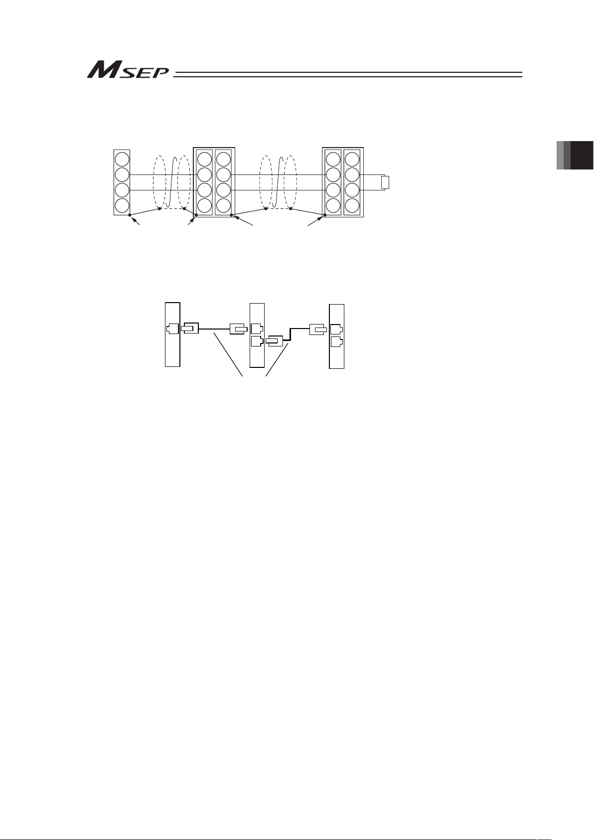
Chapter 2 Wiring
55
6) MECHATROLINK Type
7) EtherNetCAT Type
4
3
2
1
4
3
2
1
4
3
2
1
A4
A3
A2
A1
B4
B3
B2
B1
Master Unit
Slave Devices
MECHATROLINK
Cable
MECHATROLINK Cable
MSEP
MECHATROLINK Type
Terminal Resistance
JEPMC-W6022
Connect the terminal resistor
if the unit is placed at the end
of the network.
130
Ω
SH
DATA
/DATA
NC
Connect shield to
connector shell
Connect shield to
connector shell
SH
DATA
/DATA
NC
SH
DATA
/DATA
NC
Master Unit
Slave Devices
EtherNet Straight Cable
Category 5e or more
Double shielded cable braided with aluminum
foil recommended
(Note) Terminal resistance is not required
MSEP Unit
EtherCAT Type
Page 64

Chapter 2 Wiring
56
2.4 Wiring Method
2.4.1 Connection to Power Input Connector
The wire of the power supply is to be connected to the enclosed connector (plug).
Strip the sheath of the applicable wires for 10mm and insert them to the connector. Push a
protrusion beside the cable inlet with a small slotted screwdriver to open the inlet. Once the
cable is inserted, take the slotted screwdriver OFF the protrusion to fix the cable to the terminal.
㩷
Connector Name Power Line Input Connector
Cable Side FKC2.5HC/4-ST-5.08 Enclosed in standard
package
Manufactured by
PHOENIX CONTACT
Controller Side MSTBA2.5HC/4-G-5.08
Pin No. Signal Name Description Applicable cable diameter
1 0V
1
2
3
4
2 CP+24V
Power Input for Control
(24V DC ±10%)
KIV0.3mm
2
(AWG22)
3 0V
Front view of
connector on
controller side
4 MP+24V
Power Input for Motor
Drive
(24V DC ±10%)
KIV2.5 to 0.5mm
2
(AWG12 to 20)
Select the cable thickness
allowable for the current
figured out in the power
capacity.
(Note) If supplying power with using a 24V DC, having it turned ON/OFF, keep the 0V
connected and have the +24V supplied/cut (cut one side only).
Accessory
Connector
(Plug)
Page 65

Chapter 2 Wiring
57
2.4.2 Wiring Layout of System I/O Connector
The connector consists of the emergency stop input for the whole controller, changeover of the
operation modes (AUTO/MANU) externally and the external regenerative resistor connection
terminals.
Insert the wires to the enclosed connector (plug). Strip the sheath of the applicable wires for
10mm and insert them to the connector. Push a protrusion beside the cable inlet with a small
slotted screwdriver to open the inlet. Once the cable is inserted, take the slotted screwdriver
OFF the protrusion to fix the cable to the terminal.
Connector Name System I/O Connector
Cable Side FMCD1.5/4-ST-3.5 Enclosed in standard
package
Manufactured by
PHOENIX CONTACT
1
2
3
4
6
7
8
5
Controller Side
MCDN1.5/4-G1-3.5P26THR
Pin No. Signal Name Description Applicable cable diameter
1 EMG+24V
+24V power output for
emergency stop
2 S2
For external emergency
stop signal input
3 S1
For external emergency
stop signal output
4 EMG-
Emergency Stop Input
(available for all the
slots)
5 AUTO/MANU+
For operation mode
(AUTO/MANU)
switchover
6 AUTO/MANU-
Operation mode
(AUTO/MANU)
switchover signal input
KIV0.5 to 0.2mm
(AWG20 to 24)
7 RB+
Regenerative resistor
connection +
Front view of
connector on
controller side
8 RB-
Regenerative resistor
connection -
Dedicated regenerative
resistor connection
Page 66
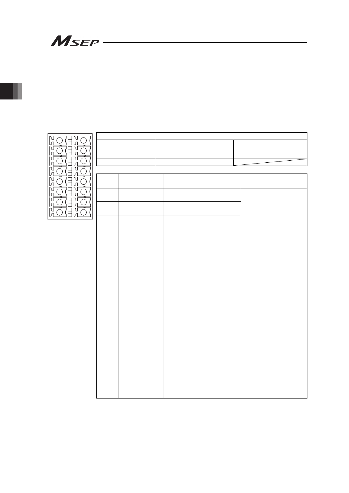
Chapter 2 Wiring
58
2.4.3 Connection of Drive Cutoff/Emergency Stop Input Connector
Insert wires if an emergency stop input is desired individually for each slot or drive cutoff for
each slot. Unless it is desired, the controller can be used in the condition that the enclosed
short-circuit line is connected.
Insert the wires to the enclosed connector (plug). Strip the sheath of the applicable wires for
10mm and insert them to the connector. Push a protrusion beside the cable inlet with a small
slotted screwdriver to open the inlet. Once the cable is inserted, take the slotted screwdriver
OFF the protrusion to fix the cable to the terminal.
㩷
㩷
Connector Name Drive Cutoff/Emergency Stop Input Connector
Cable Side
FMCD1.5/8-ST-3.5
Enclosed in standard package
Manufactured by PHOENIX
CONTACT
Controller Side MCDN1.5/8-G1-3.5P26THR
Pin No. Signal Name Description
Applicable cable
diameter
1 MPOSLOT1
For motor power output slot 1
(Axis No. 2 and 3)
2 MPISLOT1
For motor power input slot 1
(Axis No. 2 and 3)
3 MPOSLOT0
For motor power output slot 0
(Axis No. 0 and 1)
4 MPISLOT0
For motor power input slot 0
(Axis No. 0 and 1)
KIV1.25 to 0.5mm
2
(AWG16 to 20)
Select the cable
thickness allowable for
the current figured out in
the power capacity.
1
2
3
4
5
7
8
6
9
10
11
12
13
14
15
16
Front view of connector
on controller side
5
EMG+24VSLOT1
For emergency stop power
output slot 1 (Axis No. 2 and 3)
6 EMGINSLOT1
For emergency stop power
input slot 1 (Axis No. 2 and 3)
7
EMG+24VSLOT0
For emergency stop power
output slot 0 (Axis No. 0 and 1)
8 EMGINSLOT0
For emergency stop power
input slot 0 (Axis No. 0 and 1)
KIV0.5 to 0.2mm
(AWG20 to 24)
9 MPOSLOT3
For motor power output slot 3
(Axis No. 6 and 7)
10 MPISLOT3
For motor power input slot 3
(Axis No. 6 and 7)
11 MPOSLOT2
For motor power output slot 2
(Axis No. 4 and 5)
12 MPISLOT2
For motor power input slot 2
(Axis No. 4 and 5)
KIV1.25 to 0.5mm
2
(AWG16 to 20)
Select the cable
thickness allowable for
the current figured out in
the power capacity.
13
EMG+24VSLOT3
For emergency stop power
output slot 3 (Axis No. 6 and 7)
14 EMGINSLOT3
For emergency stop power
input slot 3 (Axis No. 6 and 7)
15
EMG+24VSLOT2
For emergency stop power
output slot 2 (Axis No. 4 and 5)
16 EMGINSLOT2
For emergency stop power
input slot 2 (Axis No. 4 and 5)
KIV0.5 to 0.2mm
(AWG20 to 24)
Page 67

Chapter 2 Wiring
59
2.4.4 Connecting with Actuator
Connect the relay cables to the actuator connectors.
Check in the instruction manual of each actuator for the details of the relay cables.
㩷
Connector Name Actuator Connector
Cable Side PADP-24V-1-S
Controller Side S24B-PADSS-1
Pin No. Signal Name Description Applicable cable diameter
1
IA
Motor Driving A-phase
2 VMM Motor Power
3
IB
Motor Driving B-phase
4 VMM Motor Power
5
I/A
Motor Driving /A-phase
6
I/B
Motor Driving /B-phase
7 LS+
Limit Switch Positive
Side
8 LS-
Limit Switch Negative
Side
9 BK+
Brake Release Positive
Side
10 BK-
Brake Release Negative
Side
11 NC Not for use
12 NC Not for use
13 A+
Encoder A-phase
differential + input
14 A-
Encoder A-phase
differential - input
15 B+
Encoder B-phase
differential + input
16 B-
Encoder B-phase
differential - input
17 5V Encoder Power Supply
18 /PS
Encoder Line Driver
Enable Output
19 GND Ground
20 LSGND Ground for Limit Switch
21 NC Disconnected
22 NC Disconnected
23 NC Disconnected
Front view of
connector on
controller side
24 FG Grounding
Cable dedicated for IAI
products
Page 68

Chapter 2 Wiring
60
2.4.5 Connection of Absolute Battery Connector
Connect the absolute battery unit to the controller for Simple Absolute Type.
㩷
Connector Name Absolute Battery Connector
Cable Side CZHR-20V-S
Controller Side S20B-CZWHS-B-1
Pin No. Signal Name Description Applicable cable diameter
A1 GND 0V
A2
BATTMP AXIS
No.0
Axis No.0 Absolute Battery
Temperature Sensor
A3
BATTMP AXIS
No.1
Axis No.1 Absolute Battery
Temperature Sensor
A4
BATTMP AXIS
No.2
Axis No.2 Absolute Battery
Temperature Sensor
A5
BATTMP AXIS
No.3
Axis No.3 Absolute Battery
Temperature Sensor
A6 GND 0V
A7
BATTMP AXIS
No.4
Axis No.4 Absolute Battery
Temperature Sensor
A8
BATTMP AXIS
No.5
Axis No.5 Absolute Battery
Temperature Sensor
A9
BATTMP AXIS
No.6
Axis No.6 Absolute Battery
Temperature Sensor
A10
BATTMP AXIS
No.7
Axis No.7 Absolute Battery
Temperature Sensor
B10 GND 0V
B9 BAT AXIS No.0 Axis No.0 Absolute Battery
B8 BAT AXIS No.1 Axis No.1 Absolute Battery
B7 BAT AXIS No.2 Axis No.2 Absolute Battery
B6 BAT AXIS No.3 Axis No.3 Absolute Battery
B5 GND 0V
B4 BAT AXIS No.4 Axis No.4 Absolute Battery
B3 BAT AXIS No.5 Axis No.5 Absolute Battery
B2 BAT AXIS No.6 Axis No.6 Absolute Battery
A1
A2
A3
A4
A9
A10
A6
A7
A8
A5
B10
B9
B8
B7
B6
B5
B4
B3
B2
B1
Front view of
connector on
controller side
B1 BAT AXIS No.7 Axis No.7 Absolute Battery
Cable dedicated for IAI
products
Page 69

Chapter 2 Wiring
61
2.4.6 Connection of External Brake Connector
Connection needs to be established when an external brake release is required for the actuator.
The brake can be released if the power (24V DC 150mA/axis) is supplied to this connector even
without the main power supplied to the controller.
㩷
Connector Name System I/O Connector
Cable Side FMCD1.5/5-ST-3.5 Enclosed in standard
package
Manufactured by
PHOENIX CONTACT
Controller Side MCDN1.5/5-G1-3.5P26THR
Pin No. Signal Name Description Applicable cable diameter
1 BKRLS AXIS No.3
Axis No.3 Brake
Release Input
2 BKRLS AXIS No.2
Axis No.2 Brake
Release Input
3 BKRLS AXIS No.1
Axis No.1 Brake
Release Input
4 BKRLS AXIS No.0
Axis No.0 Brake
Release Input
5 GND 0V
6 BKRLS AXIS No.7
Axis No.7 Brake
Release Input
7 BKRLS AXIS No.6
Axis No.6 Brake
Release Input
8 BKRLS AXIS No.5
Axis No.5 Brake
Release Input
9 BKRLS AXIS No.4
Axis No.4 Brake
Release Input
1
2
3
4
5
7
8
9
10
6
Front view of
connector on
controller side
10 GND 0V
KIV0.5 to 0.2mm
(AWG20 to 24)
Page 70

Chapter 2 Wiring
62
2.4.7 Connection of SIO Connector
Connect an teaching tool such as the PC software.
(Note) Do not attempt connect the device to the same SIO network as the CON related
controllers such as PCON.
Teaching Pendant
PC Software
MSEP
㩷
Connector Name SIO Connector
Cable Side miniDIN 8-pin
Controller Side TCS7587-0121077
Pin No. Signal Name Description Applicable cable diameter
1
SGA
Teaching Tool Signal +
2
SGB
Teaching Tool Signal -
3
5V
Power supply for teaching tool
4
ENB
Enable signal input
5 EMGA Emergency Stop Signal A
6 24V Power supply for teaching tool
7 0V 0V
8 EMGB Emergency Stop Signal B
Shell 0V 0V
Cable dedicated for IAI
products
Page 71

Chapter 2 Wiring
63
2.4.8 Connection of PIO (for PIO Type)
The connection of I/O to the controller is to be carried out using the dedicated I/O cable. The
cable length is shown in the model code of the controller. There are 2m for standard, 3m and
5m as an option. 10m is also applicable at maximum if purchased separately. [Refer to 1.1.5
How to read the model]
Also, the end of the cable harness to be connected to the host controller (PLC, etc.) is just cut
and no treatment is conducted so the wiring layout can be performed freely.
Model: CB-MSEP-PIOƑƑƑ (ƑƑƑ indicates the cable length L. Example. 020 = 2m)
Flat Cable (34-core) × 2
YW-8 (34B)
BR-5 (1B)
YW-4 (34A)
BR-1 (1A)
34A 34B
1A 1B
Half Pitch MIL Socket
HIF6-68D-1.27R (Hirose Electric)
A
B
L
No treatment
conducted
No treatment
conducted
No. Cable Color Wiring No. Cable Color Wiring
1A BR-1 1B BR-5
2A RD-1 2B RD-5
3A OR-1 3B OR-5
4A YW-1 4B YW-5
5A GN-1 5B GN-5
6A BL-1 6B BL-5
7A PL-1 7B PL-5
8A GY-1 8B GY-5
9A WT-1 9B WT-5
10A BK-1 10B BK-5
11A BR-2 11B BR-6
12A RD-2 12B RD-6
13A OR-2 13B OR-6
14A YW-2 14B YW-6
15A GN-2 15B GN-6
16A BL-2 16B BL-6
17A PL-2 17B PL-6
18A GY-2 18B GY-6
19A WT-2 19B WT-6
20A BK-2 20B BK-6
21A BR-3 21B BR-7
22A RD-3 22B RD-7
23A OR-3 23B OR-7
24A YW-3 24B YW-7
25A GN-3 25B GN-7
26A BL-3 26B BL-7
27A PL-3 27B PL-7
28A GY-3 28B GY-7
29A WT-3 29B WT-7
30A BK-3 30B BK-7
31A BR-4 31B BR-8
32A RD-4 32B RD-8
33A OR-4 33B OR-8
34A YW-4
Flat CableżA
(Press Welding)
AWG28
34B YW-8
Flat Cable
ż
B
(Press Welding)
AWG28
Page 72

Chapter 2 Wiring
64
2.4.9 Wiring Layout of Fieldbus Connector
Check the instruction manuals for each Fieldbus master unit and mounted PLC for the details.
1) DeviceNet Type
Shield
BL (CAN L)
RD (V+)
WT (CAN H)
BK (V-)
Connector Name DeviceNet Connector
Cable Side MSTB2.5/5-ST-5.08 ABGY AU Enclosed in standard
package
Manufactured by
PHOENIX CONTACT
Controller Side MSTBA2.5/5-G-5.08 ABGY AU
Pin No.
Signal Name
(Color)
Description
Applicable cable
diameter
1
2
3
4
5
1 V- (BK)
Power Supply Cable
Negative Side
Front view of connector
on controller side
2 CAN L (BL)
Communication Data
Low Side
3 Shield (None) Shield
4 CAN H (WT)
Communication Data
High Side
5 V+ (RD)
Power Supply Cable
Positive Side
Dedicated cable for
DeviceNet
Note Connect a terminal resistor (121:) between CAN L and CAN H if
the unit comes to the end of the network. [Refer to 2.3 [8] Wiring
Layout for Fieldbus.]
Page 73
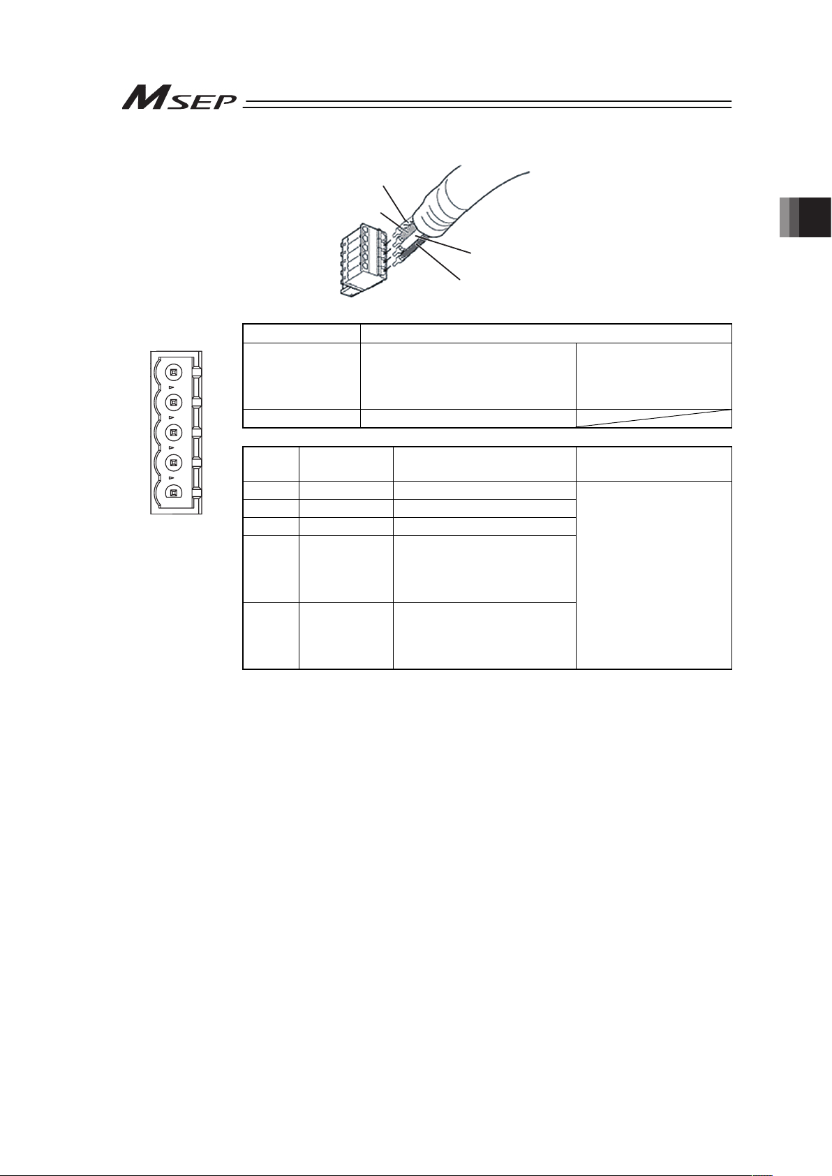
Chapter 2 Wiring
65
2) CC-Link Type
WT (DB)
BL (DA)
Shield (SLD)
YW (DG)
Connector Name CC-Link Connector
Cable Side MSTB2.5/5-ST-5.08 ABGY AU Enclosed in standard
package
Manufactured by
PHOENIX CONTACT
Controller Side MSTBA2.5/5-G-5.08AU
Pin No.
Signal Name
(Color)
Description
Applicable cable
diameter
1 DA (BL) Communication Line A
1
2
3
4
5
2 DB (WT) Communication Line B
3 DG (YW) Digital GND
4
SLD Connect the shield of the
shielded cable (Connect the
FG of the 5 pins and
controller FG internally)
Front view of
connector on
controller side
5
FG Frame Ground
(Connect the SLD of the 4
pins and controller FG
internally)
Dedicated cable for
CC-Link
Note Connect a terminal resistor between DA and DB if the unit comes to the
end of the network. [Refer to 2.3 [8] Wiring Layout for Fieldbus.]
Page 74

Chapter 2 Wiring
66
3) PROFIBUS-DP Type
5 1
9 6
Cable
Shield
Red B line (Positive side)
Use the type A cable for PROFIBUS-DP (EN5017).
Green A line (Negative side)
Connector Name PROFIBUS-DP Connector
Cable Side 9-pin D-sub Connector (Male) Please prepare separately
Controller Side 9-pin D-sub Connector (Female)
Pin No. Signal Name Description
Applicable cable
diameter
1 NC Disconnected
2 NC Disconnected
1
6
9
5
3
B-Line Communication Line B
(RS485)
4 RTS Request for Sending
5 GND Signal GND (Insulation)
Front view of
connector on
controller side
6 +5V +5V Output (Insulation)
7 NC Disconnected
8
A-Line Communication Line A
(RS485)
9 NC Disconnected
PROFIBUS-DP
Dedicated Cable
Note Connect a terminal resistor (220:) between A-line and B-line if the unit
comes to the end of the network. [Refer to 2.3 [8] Wiring Layout for
Fieldbus.]
Page 75

Chapter 2 Wiring
67
4) CompoNet Type
Connector Name CompoNet Connector
Cable Side Prepare a connector complied with CompoNet standards.
Controller Side XW7D-PB4-R Produced by OMRON
Pin No.
Signal Name
(Color)
Description
Applicable cable
diameter
1 BS+ (RD)
Communication Power
Supply +
(Note 1)
2 BDH (WT) Signal line H side
3 BDL (BL) Signal line L side
Front view of
connector on
controller side
4 BS- (BK)
Communication Power
Supply -
(Note 1)
CompoNet Dedicated
Cable
Note 1 It is not necessary to supply the communication power. (Internal
power source is used.)
If conducting multi power supply to other slave devices via
communication cables, there is no problem with connecting the
power supply to BS+ and BS- terminals.
Note 2 Connect a terminal resistor (121:) between BDH and BDL if the unit
comes to the end of the network. [Refer to 2.3 [8] Wiring Layout for
Fieldbus.]
5) EtherNet/IP Type
Connector Name EtherNet/IP Connector
Cable Side 8P8C Modular Plug
Controller Side 8P8C Modular Jack
Pin No. Signal Name Description
Applicable cable
diameter
1 TD+ Data sending +
2 TD- Data sending 3 RD+ Data receiving +
Front view of
connector on
controller side
4 – Disconnected
5 – Disconnected
6 RD- Data receiving 7 – Disconnected
8 – Disconnected
For EtherNet cable, use
a straight STP cable
that possesses the
performance of
Category 5e or more.
BK (BS-)
BL (BDL)
RD (BS+)
WT (BDH)
1
2
3
4
1
8
Page 76

Chapter 2 Wiring
68
6) MECHATROLINK Type
Connector Name MECHATROLINK Connector
Cable Side Prepare a connector complied with MECHATROLINK
standards.
Controller Side DUSB-ARB82-T11A-FA Produced by DDK
Pin No. Signal Name Description
Applicable cable
diameter
A1/B1 NC Disconnected
A2/B2 /DATA Signal line - side
A3/B3 DATA Signal line + side
Front view of
connector on
controller side
A4/B4 SH Shield
MECHATROLINK
Dedicated Cable
Note Connect a terminal resistor unit (JEPMC-W6022) between DATA and
/DATA if the unit comes to the end of the network. [Refer to 2.3 [8]
Wiring Layout for Fieldbus.]
7) EtherCAT Type
Connector Name EtherCAT Connector
Cable Side 8P8C Modular Plug
Controller Side 8P8C Modular Jack
Pin No. Signal Name Description
Applicable cable
diameter
1 TD+ Data sending +
2 TD- Data sending 3 RD+ Data receiving +
4 – Disconnected
5 – Disconnected
6 RD- Data receiving 7 – Disconnected
Front view of
connector on
controller side
8 – Disconnected
For EtherNet cable, use
a straight STP cable
that possesses the
performance of
Category 5e or more.
B1
A1
A4
B4
8
1
8
1
Page 77
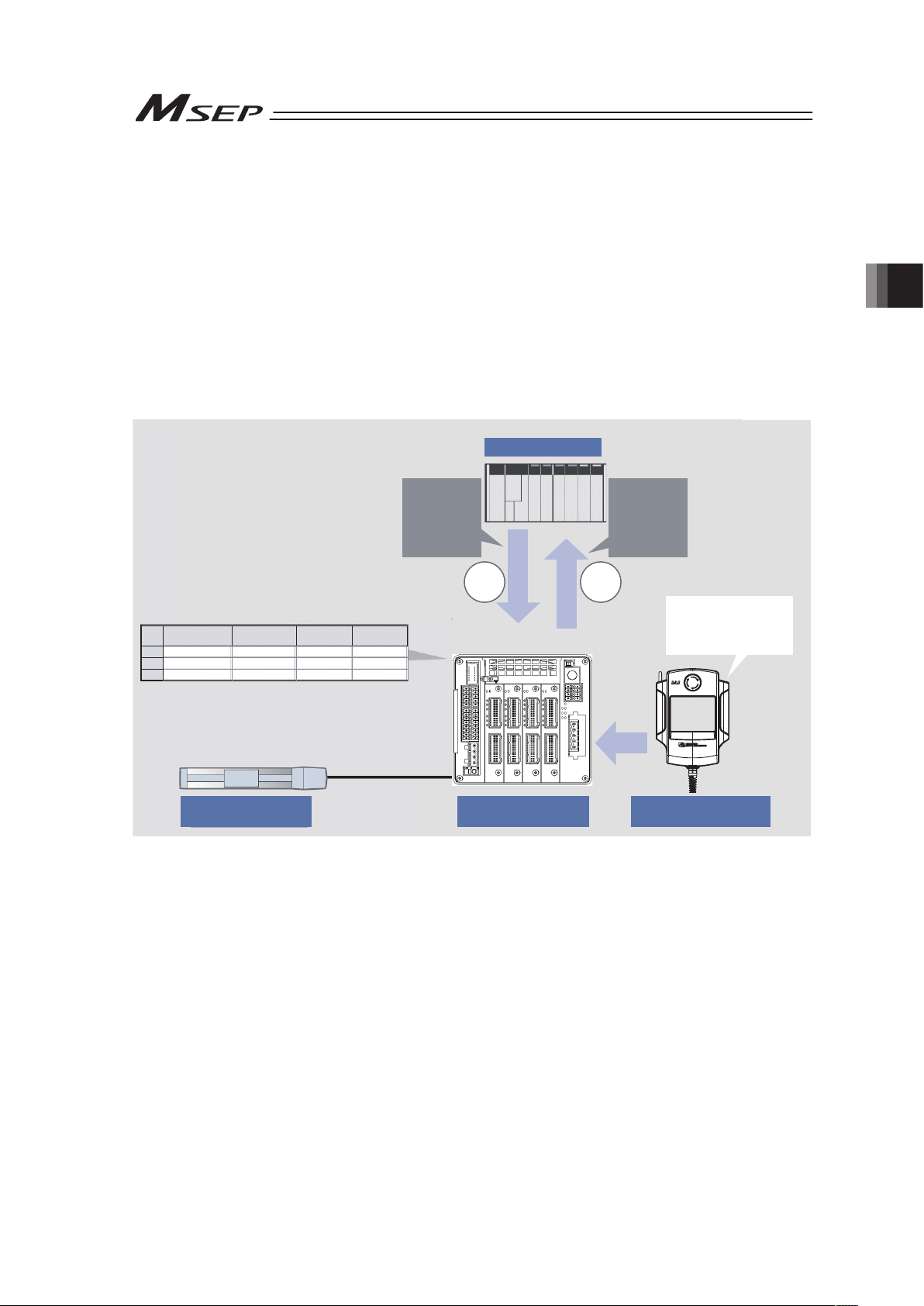
Chapter 3 Operation
69
Chapter 3 Operation
3.1 Basic Operation
3.1.1 Basic Operation Methods
There are two ways for the operation; one is to control with PIO and the other with Fieldbus.
Check the model code described on the model code record card inserted on the front panel of
the unit to find which way is to be applied for your product. [Refer to 1.1.5]
Even though there are several types for an actuator, such as slider type, rod type, rotary type,
gripper type, etc., the method to control the operation is the same unless otherwise specified in
this manual.
(1) Control with PIO
Edit Position
Table of
controller
Actuator
Controller
PLC
Teaching Tool
Complete
Signal
SignalSignal
Move
Signal
Enter a data including
position, speed,
acceleration or
deceleration, etc.
No.
[G]
0
1 100.00 0.30 0.30
2 200.00 0.30 0.30
100.00
200.00
Acceleration DecelerationSpeed
[mm] [mm/s]
[G]
Position
1) Conduct the settings for the target position (such as forward end or backward end), speed
and acceleration/deceleration data that are necessary to be filled in the position table using
a teaching tool such as PC software.
2) Turn ON the movement signal of the target position from PLC.
3) The actuator is placed at the proper coordinate value according to the positioning
information in the specified target position.
4) The complete signal or position detection signal is output once the positioning is complete.
That is all for the basic operation method to control with PIO.
Page 78

3.1 Basic Operation
70
ƔOperation Mode Available in PIO Type
6 types of operation modes (PIO Patterns) are available to select from.
Explained below is the outline. Also, in the table below, provides the relevant air cylinder circuit
for reference.
Operation Pattern Description
Example for Electric Cylinder
Connection
Example for Air Cylinder
Connection (Reference)
PIO Pattern 0
Single Solenoid System
(Standard Point-to-Point
Movement)
PLC
+24V
Movement Signal
(ST0)
Backward
Position Detection
(LS0)
Forward
Position Detection
(LS1)
Dedicated
Cable
Electric Cylinder
MSEP
R2 R1
B A
Spring
Solenoid
Air Cylinder
PLC
Movement Signal
(ST0)
P(Air)
Forward
Position Detection
(LS1)
Backward
Position Detection
(LS0)
PIO Pattern 0
Double Solenoid System
(Standard Point-to-Point
Movement)
The actuator
point-to-point movement
is available using the
same control function as
for the air cylinder.
The target position setting
(forward position and
backward position) is
available.
Speed and acceleration
settings in the actuator
movement are available.
The pressing operation is
available.
+24V
PLC
Backward Position
Movement Signal
(ST0)
Forward Position
Movement Signal
(ST1)
Backward
Position Detection
(LS0)
Forward
Position Detection
(LS1)
Dedicated
Cable
Electric Cylinder
MSEP
R2 R1
B A
Solenoid
Solenoid
Air Cylinder
PLC
P(Air)
Movement Signal
(ST0)
Forward Position
Movement Signal
(ST1)
Backward
Position Detection
(LS0)
Forward
Position Detection
(LS1)
PIO Pattern 1
Single Solenoid System
(Point-to-Point Movement,
Movement Speed Setting)
+24V
PLC
Movement Signal
(ST0)
Movement Speed
Change Signal
(SPDC)
Backward
Position Detection
(LS0)
Forward
Position Detection
(LS1)
Dedicated
Cable
Electric Cylinder
MSEP
Spring
R2
R1
B A
Solenoid
Air Cylinder
PLC
P(Air)
Movement Signal
(ST0)
Movement Speed
Change Signal
(SPDC)
Backward
Position Detection
(LS0)
Forward
Position Detection
(LS1)
PIO Pattern 1
Double Solenoid System
(Point-to-Point Movement,
Movement Speed Setting)
The actuator
point-to-point movement
is available using the
same control function as
for the air cylinder.
The movement speed can
be changed while the
actuator is moving if the
movement speed change
signal is input.
The target position setting
(forward position and
backward position) is
available.
Speed and acceleration
settings in the actuator
movement are available.
The pressing operation is
available.
+24V
PLC
Backward Position
Movement Signal
(ST0)
Forward Position
Movement Signal
(ST1)
Movement Speed
Change Signal
(SPDC)
Backward
Position Detection
(LS0)
Forward
Position Detection
(LS1)
Dedicated
Cable
Electric Cylinder
MSEP
R2
R1
B A
Solenoid
Solenoid
Air Cylinder
PLC
P(Air)
Backward Position
Movement Signal
(ST0)
Forward Position
Movement Signal
(ST1)
Movement Speed
Change Signal
(SPDC)
Backward
Position Detection
(LS0)
Forward
Position Detection
(LS1)
Page 79
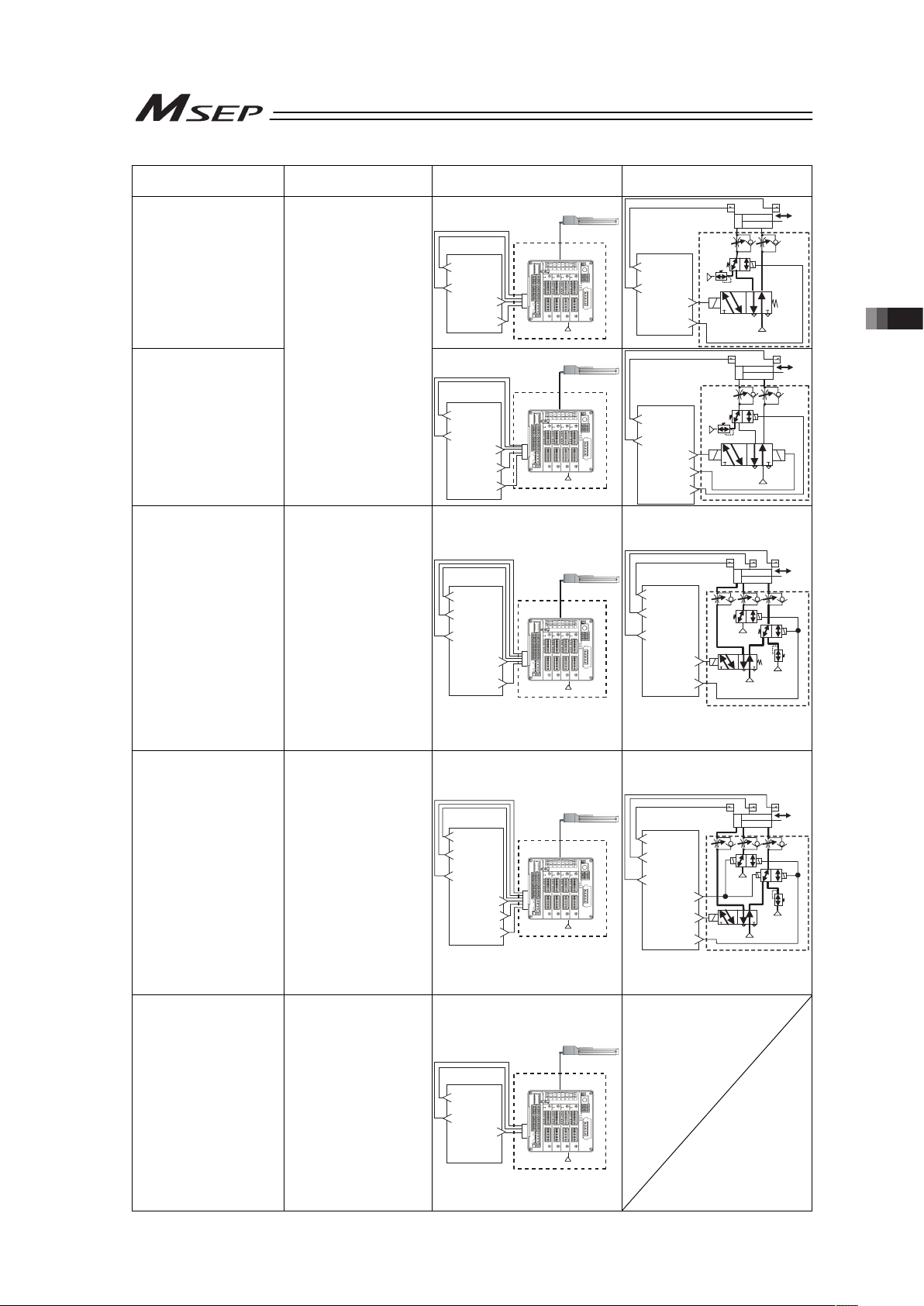
3.1 Basic Operation
71
Operation Pattern Description
Example for Electric Cylinder
Connection
Example for Air Cylinder
Connection (Reference)
PIO Pattern 2
Single Solenoid System
(Point-to-Point Movement,
Target Position Setting
(Position Data) Change)
+24V
PLC
Movement Signal
(ST0)
Target Position
Change Signal
(CN1)
Backward
Position Detection
(LS0)
Forward
Position Detection
(LS1)
Dedicated
Cable
Electric Cylinder
MSEP
R2
R1
B A
Air Cylinder
PL C
P(Air)
P(Air)
Movement Signal
(ST0)
Target Position
Change Signal
(CN1)
Backward
Position Detection
(LS0)
Forward
Position Detection
(LS1)
PIO Pattern 2
Double Solenoid System
(Point-to-Point Movement,
Target Position Setting
(Position Data) Change)
The actuator
point-to-point movement
is available using the
same control function as
for the air cylinder.
The target position and
operation condition can
be changed while the
actuator is moving if the
target position change
signal is input.
The target position setting
(forward position and
backward position) is
available.
Speed and acceleration
settings in the actuator
movement are available.
The pressing operation is
available.
+24V
PLC
Backward Position
Movement Signal
(ST0)
Forward Position
Movement Signal
(ST1 )
Target Position
Change Signal
(CN1)
Backward
Position Detection
(LS0)
Forward
Position Detection
(LS1)
Dedicated
Cable
Electric Cylinder
MSEP
R2
R1
B
A
Air Cylinder
PLC
P(Air)
P(Air)
Backward Position
Movement Signal
(ST0)
Forward Position
Movement Signal
(ST1 )
Target Position
Change Signal
(CN1)
Backward
Position Detection
(LS0)
Forward
Position Detection
(LS1)
PIO Pattern 3
(2-Input, 3-Point
Movement)
The actuator 3-Point
Movement is available
using the same control
function as for the air
cylinder.
The target position setting
(forward position,
backward position and
intermediate position) is
available.
Speed and acceleration
settings in the actuator
movement are available.
Pressing operation is
available at the points
except for the
intermediate point.
+24V
PLC
Movement
Signal 1
(ST0)
Movement
Signal 2
(ST1 )
Backward
Position Detection
(LS0)
Forward
Position Detection
(LS1)
Intermediate
Position Detection
(LS2)
Dedicated
Cable
Electric Cylinder
MSEP
Air Cylinder
PLC
P(Air)
P(Air)
P(Air)
Movement
Signal 1
(ST0)
Movement
Signal 2
(ST1 )
Backward
Position Detection
(LS0)
Forward
Position Detection
(LS1)
Intermediate
Position Detection
(LS2)
PIO Pattern 4
(3-Input, 3-Point
Movement)
The actuator 3-Point
Movement is available
using the same control
function as for the air
cylinder.
The target position setting
(forward position,
backward position and
intermediate position) is
available.
Speed and acceleration
settings in the actuator
movement are available.
Pressing operation is
available at the points
except for the
intermediate point.
+24V
Dedicated
Cable
PLC
Electric Cylinder
Intermediate Position
Movement Signal
(ST2)
Backward Position
Movement Signal
(ST0)
Forward Position
Movement Signal
(ST1)
Backward
Position Detection
(LS0)
Forward
Position Detection
(LS1)
Intermediate
Position Detection
(LS2)
MSEP
Air Cylinder
PLC
P(Air)
P(Air)
P(Air)
Intermediate Position
Movement Signal
(ST2)
Backward Position
Movement Signal
(ST0)
Forward Position
Movement Signal
(ST1)
Backward
Position Detection
(LS0)
Forward
Position Detection
(LS1)
Intermediate
Position Detection
(LS2)
PIO Pattern 5
(Continuous Reciprocating
Operation)
The actuator’s point-topoint reciprocating
operation is performed
between the forward
position and backward
position.
The target position setting
(forward position and
backward position) is
available.
Speed and acceleration
settings in the actuator
movement are available.
The pressing operation is
available.
+24V
PLC
Continuous
Reciprocating
Operation Signal
(ASTR)
Backward
Position Detection
(LS0)
Forward
Position Detection
(LS1)
Dedicated
Cable
Electric Cylinder
MSEP
Page 80

3.1 Basic Operation
72
(2) Fieldbus Type
Slave
Slave
Transfer data
with Fieldbus
Actuator Controller
PLC
position, speed, etc.
Command target
Confirmation of
movement complete
(read status signal)
Page 81

3.1 Basic Operation
73
[Basic Procedures for Operation]
[1] Establish the driver parameters with using a teaching tool such as PC software.
1) If using SEP I/O Mode in the operation modes [refer to the next page], set the
operation pattern in the initial setting. [Refer to 3.2 for details.]
2) Establish such settings as the zone (Parameter No.21 to 24) and the soft limit
(Parameter No.15) considering the system to be used.
[Refer to chapter 5 I/O Parameter for details.]
[2] Initial Setting [Refer to 3.2 and 3.9.]
Establish the settings such as the slave addresses for the field network using Gateway
Parameter Setting Tool. Set operation modes for all the connected axes.
1) Establish the settings by following the steps stated in Section 3.2.
2) Set the gateway parameters considering the system to be used.
Establish such settings as whether to use the calendar function (clock setting) and
the speed unit change during Direct Indication Mode.
[3] Setting of Position Data [Refer to 3.3.]
(Note) Setting is not necessary for Direct Indication Mode.
Set the information such as the target position and speed to be used in the position data.
[4] Field Network Settings [Refer to 3.4.1 and 3.4.2.]
Assign MSEP as the PLC (Master Unit).
[Refer to the instruction manuals of the master unit and PLC.]
[5] Link to Network
1) Set the operation mode setting switch on the front panel of MSEP to AUTO side, and
reboot the power. (Field network line becomes valid by setting the switch to AUTO)
2) Once the link with the PLC (Master Unit) is established
(Note 1)
, turn ON MON signal in
the gateway control signals
(Note 2)
. While MON Signal is ON, control from field network
is available.
Note 1 Confirm the communication is established in normal condition by referring to
Display of Field Network LEDs shown in the section of Name and Function of
Each Component in earlier pages of this manual.
Note 2 Refer to 3.4.3 Gateway Control Signals.
[6] Operation Control with Each Operation Mode [Refer to 3.4.4 to 3.5.]
1) Send the information of the target position, speed, acceleration/deceleration, etc.
from PLC (Master Unit) to MSEP.
2) The actuator follows the received information of the target position, speed,
acceleration/deceleration, etc. to perform a positioning at the specific coordinates.
3) Confirm the status of positioning complete.
Page 82

3.1 Basic Operation
74
ƔOperation Mode Available in Fieldbus Type
6 types of operation modes are available to select from.
Explained below is the outline.
Operation Pattern Description Overview
Positioner 1 Mode In Positioner 1 Mode, 256
points of position data can be
registered at the maximum
and is able to stop at the
registered positions.
Monitoring of the current
position is also available.
Simple Direct
Mode
In Simple Direct Mode, the
target position can be indicated
directly by inputting a value.
Monitoring of the current
position is also available.
Communication with Fieldbus
Dedicated Cable
+24V
Target Position
Target Position No.
Control Signal
PLC
Current Position
Completed Position No.
Status Signal
Electric Cylinder
Direct Numeric
Specification
Mode
The target position, speed
acceleration/deceleration
and pressing current limit can
be indicated with inputting a
number. Monitoring of not
only the current position, but
also the current speed and
indicated current are
available.
Communication with Fieldbus
+24V
Target Position
Positioning Width
Speed
Acceleration/Deceleration
Push %
Control Signal
PLC
Current Position
Current Value
(Command Value)
Current Speed
(Command Value)
Alarm Code
Status Signal
Dedicated Cable
Electric Cylinder
Positioner 2 Mode This is the operation mode of
the position data of 256
points at maximum set in the
position table. The
monitoring of the current
position is not available
This mode is that the
transferred data is reduced
from Positioner 1 Mode.
Communication with Fieldbus
+24V
Target Position No.
Control Signal
PLC
Completed Position No.
Status Signal
Dedicated Cable
Electric Cylinder
Positioner 3 Mode This is the operation mode of
the position data of 256
points at maximum set in the
position table. The
monitoring of the current
position is not available.
This is the mode to control
with the minimized number of
signals to perform the
positioning operation by
reducing the amount of sent
and received data from
Positioner 2 Mode.
Communication with Fieldbus
+24V
Target Position No.
Control Signal
PLC
Completed Position No.
Status Signal
Dedicated Cable
Electric Cylinder
SEP I/O The same control as PIO is
available.
Refer to PIO type
Page 83

3.1 Basic Operation
75
3.1.2 Parameter Settings
Parameter data should be set appropriately according to the applicaiton requirements.
(Example)
Software Stroke Limit : Set a proper operation range for definition of the stroke end, prevention
of interferences with peripherals and safety.
Zone Output : Set to require signal outputs in an arbitrary position zone within the
operation zone.
Parameters should be set to meet the use of the controller prior to operation. Once set, they
may not set every operation.
Check the Chapter 5 for the parameter types and the details.
Page 84

3.2 Initial Setting
76
3.2 Initial Setting
For this controller, it is necessary to have the initial setting and Gateway operation mode setting
done in the axes one by one.
The initial setting is to be performed using RC PC Software
(Note)
or touch panel teaching
(CON-PTA
(Note)
). And the operation mode is to be set using Gateway Parameter Setting Tool
(Ver. 1.1.0.0 or later).
(Note) See the instruction manuals of the RC PC software and the touch panel teaching for the
applicable version.
Shown below is the process for the setup. Follow the instruction to conduct the setting properly.
[Preparation] Install RC PC Software and Gateway Parameter Setting Tool. For Gateway
Parameter Setting Tool, install the file stored in the CD-ROM for PC software, or
download from our website, intelligentactuator.com.
[Refer to the instruction manual of the PC software for the details of the PC software.]
Make sure the power, system I/O connector wires and operation mode setting switch are in MANU
condition when having the setting done.
[Step 1] Connect the PC and SIO connector on MSEP with using the cable enclosed in RC PC
Software and start up the PC software.
[Step 2] Select the initial setting of SEP from the controller menu.
[Step 3] Select the axis number which the setting is to be conducted.
Page 85

3.2 Initial Setting
77
[Step 4] Select the operation pattern.
There are Operation Patterns 0 to 5 available for PIO Type.
Select Operation Pattern 6 if Fieldbus Type and a mode other than SEP I/O Mode
.
Select either of Operation Patterns 0 to 5 if Fieldbus Type and SEP I/O Mode
since control
is the same as PIO Type.
By pressing OK after the selection is made, the display proceeds to the next step for
Operation Patterns 0 to 5, and the initial setting data is sent to the controller for Operation
Pattern 6.
[Step 5] (Note) For Operation Pattern 6, proceed to Step 7.
If the operation pattern is either of 0 to 5, have the following setting. The items to set vary
depending on the operation pattern you have chosen, and will be some items that are not
shown.
Set the displayed item and click on OK button.
Statement in a bracket is the setting at the delivery.
Operation Pattern
({ : Available for Setting)
No. Setting Item
Setting Range
(Set in delivery)
Description
0 1 2 3 4 5
1 Solenoid
System
Single/Double
(Double)
Single : Actuator is operated with a control
same as Single Solenoid.
Double : Actuator is operated with a control
same as Double Solenoid System.
{ { {
2 Stop Signal Use/
Not to Use
(Not to Use)
This is available only if Single is selected in
No.1.
When the PAUSE signal (*STP) is used,
select “Use”.
{ { { {
3 Input Signal
System
Continuous
Operation Type
/Momentary
Operation Type
(Continuous
Operation
Type)
This is available only if Double is selected in
No.1.
For the signal sent from PLC to MSEP, select
“Continuous Operation” (level signal) or
“Momentary Operation” (edge signal).
(Reference) Double Solenoid Circuit
A B
R1 R2
Solenoid B
T T
Solenoid A
Solenoid A Control Signal
Solenoid B Control Signal
P (Air)
{ { { {
For Operation Pattern 6
For Operation Pattern 0 to 5
[Refer to Step 5 for the details]
Page 86

3.2 Initial Setting
78
Operation Pattern
({ : Available for Setting)
No. Setting Item
Setting Range
(Set in delivery)
Description
0 1 2 3 4 5
4 Intermediate
Stop System
Both Solenoid
ON/
Both Solenoid
OFF
(Both Solenoid
OFF)
This is available only if Operation Pattern 3 is
selected. Select whether to have the
movement to the intermediate point
performed with the forward end movement
command and backward end movement
command both being turned OFF or both
turned ON.
In the case the same use procedure as for
5-port 3-position electromagnetic valve is
applied, select “Both Solenoid OFF”.
In the case that the same use procedure as
the time when two units of the 3-port single
solenoid electromagnetic valve, are used,
select “Both Solenoid ON”.
{
5 Servo
Control
Use/
Not to Use
(Not to Use)
When “Not to Use” is selected, the
servo-motor is automatically turned ON after
the power input.
When “Use” is selected, servo is turned ON
only while CON signal of the input IN3 is ON.
{ { { { { {
6 Home
Position
Operation
AUTO/MANU
(MANU)
If AUTO is selected, the home-return
operation is started automatically when the
servo is turned for the first time after the
power is supplied.
“MANU” is selected, the home return
operation is performed with the first
movement signal (ST0) input.
{ { { { { {
7 Output
Signal Type
Limit Switch
Output/
Completed
Position Output
(Limit Switch)
Select the output system for the positioning
complete signal.
• Limit Switch Output
After home return operation, it turns ON
when in the range of
forward/intermediate/backward
positioning width no matter of servo
ON/OFF or the movement if there is ore
there is not.
Intermediate Point is reached : LS2 ON
Forward End is reached. : LS1 ON
Backward End is reached. : LS0 ON
• Completed Position Output
When the actuator reaches the target
position, it is turned ON. This signal
turns OFF with the servo being OFF.
When the servo-motor is turned ON
again and the current position is within
the positioning width, it is turned ON.
Intermediate Point is reached : PE2 ON
Forward End is reached. : PE1 ON
Backward End is reached. : PE0 ON
(Note) It becomes OFF before home return
operation no matter which output
method.
[Refer to Section 3.8.2 for the details.]
{ { { { { {
Page 87

3.2 Initial Setting
79
Operation Pattern
({ : Available for Setting)
No. Setting Item
Setting Range
(Set in delivery)
Description
0 1 2 3 4 5
8 Output
Signal
Selection
0 to 2
(0)
If “Use” is selected in No. 5 Servo Control,
select the combination of the used output
signals considering the operation pattern.
Select 0 if “Not to Use” is selected.
• For Operation Patterns 0 to 2 and 5,
select from the combinations 0 to 2 below.
0 : OUT2 = HEND
OUT3 = *ALM
(No servo-on signal output)
1 : OUT2 = SV
OUT3 = *ALM
2 : OUT2 = HEND
OUT3 = SV
• For Operation Patterns 3 and 4,
select from the combinations 0 and 1
below.
0 : OUT3 = *ALM
(No servo-on signal output)
1 : OUT3 = SV
[Refer to Section 3.8.2 for the details.]
{ { { { { {
Page 88

3.2 Initial Setting
80
[Step 6] The confirmation window for controller reboot opens. Click “Yes”.
[Step 7] The initial setting needs to be held on all the MSEP composition axes. In the case that
multiple axes are connected, repeat the Steps 2 to 6.
Once the setting on all the connected axes is finished, close RC PC Software.
We now move on the Gateway operation mode setting.
[Step 8] Start up Gateway Parameter Setting Tool.
The following window appears. Select MSEP GW and click OK.
[Step 9] The connected MSEP (unit number) becomes available to select. Select the unit number to
be connected and click on the OK button.
Page 89

3.2 Initial Setting
81
[Step 10] Main Window is displayed.
[Step 11] Reading is started from MSEP to PC. Click on the “Read” button and a confirmation
window appears. Click on the “Yes” button.
Once the parameter reading is completed in normal condition, the reading complete
window opens. Click OK.
Page 90
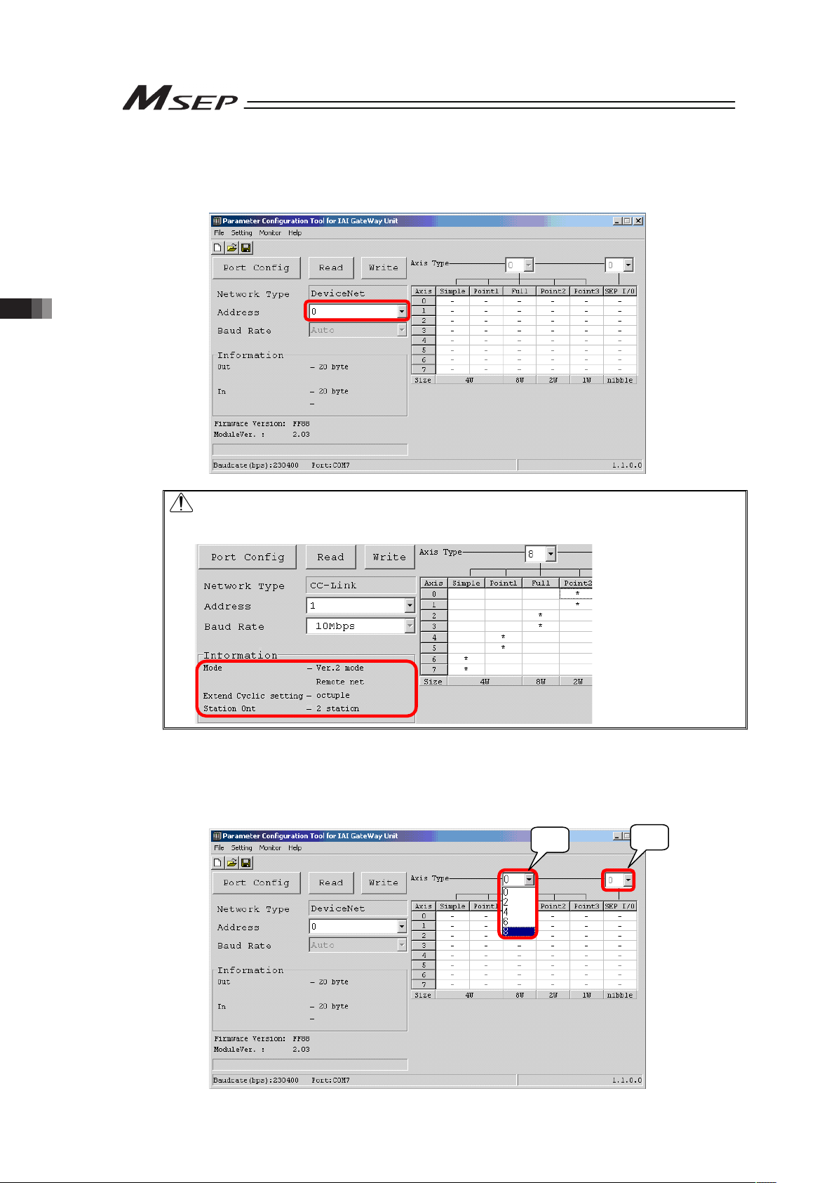
3.2 Initial Setting
82
[Step 12] For PIO Type, proceed to Step 13.
The parameters input to MSEP are listed as shown below. Indicate the node address
(station) of MSEP on field network in Address.
Caution for CC-Link Type station setting
In the following slave, set the value the number of occupied station is added to the
current station number.
[Step 13] Set the number of axes (two axes in unit) used in each operation mode. If the system is
used in Positioner Modes 1 to 3, Simple Direct Mode or Positioning Mode, input the total
number of the axes in 1) in the figure below. Input the total number of axes in 2) if using in
SEP I/O Mode. Note that 1) and 2) cannot be used at the same time.
1)
2)
Page 91

3.2 Initial Setting
83
[Step 14] Once the setting of the number of axes is done, the cells for the operation mode settable to
each axis turn to blank in response. For PIO Type and SEP I/O Mode, “*” is displayed for a
number equals to the number of set axis.
[Step 15] Click on a blank cell and “*” shows up. “*” mark means that an operation mode is selected
for each axis.
Select an operation mode [refer to top in Chapter 3] for 2 axes in a unit. If clicking on a cell,
“*” shows up for 2 axes together. If clicking a cell showing “*”, the mark turns to “(*)”. “(*)”
means it is a reserved axis, which is to be set when not using even though the actuator is
connected.
If clicking on a cell with “(*)” mark for the reserved axes shown on the two axes, the cell
turns back to blank.
(Note) Even if the total number of the used axes is an odd number, make the last axis in
reservation to get an even number.
[Step 16] To be conducted only for EtherNet/IP type (If not applied, go to Step 17)
Click on Setting in the menu and select EtherNet/IP Setting, and the setting window of the
IP addresses, subnet mask and default gateway. Establish the setting that suits to your
use.
Page 92

3.2 Initial Setting
84
[Step 17] Write the edited operation mode setting parameters to MSEP. Click on the “Write” button
shown below and a confirmation window pops up. Click on the “Yes” button.
If the writing is finished in normal condition, writing complete window appears. Click OK.
[Step 18] A confirmation window for Gateway Unit reboot opens. Click “Yes” to accept the reboot.
[Step 19] After rebooting, a confirmation window for parameter reading appears for confirmation of
the written contents. Click “Yes” to accept the reading.
Once the reading process is complete, confirm that the written contents are reflected.
If not written properly, do the process again from Step 1.
Reference:
The settings are conducted in the special parameters for the process of communication error,
change in pressing method for Fieldbus Type and speed unit change for Direct Indication Mode.
Refer to 3.9 About Gateway Parameter Setting Tool for the details.
Page 93
3.3 Setting of Position Data
85
3.3 Setting of Position Data
PIO Type makes an operation based on the position data (position, speed, etc.) set in advance
in the position table. Set the target position (forward end, backward end and intermediate point
(Note)
) first.
(Note) The setting may not be made for some operation modes.
The values in the position table can be set as shown below.
[1] Settings in common for all operation patterns
For Operation Patterns 1 and 2, there are additional settings to be conducted separately in
[2] and [3] to be referred for the setting process.
Example for Position Table Setting (when Operation Patterns 0 to 5 and Operation Pattern 6 of SEP
I/O Mode)
1) Position Name
2) Position
[mm]
3) Speed
[mm/s]
4) Pressing
Force
[%]
5) Pressing
Width
[mm]
6) Acceleration
[G]
7) Deceleration
[G]
8) Energy-Saving
Setting
Backward End
Position
0.00 50.00 0 0 0.1 0.1 0
Forward End
Position
200.00 50.00 70 1.00 0.1 0.1 1
Intermediate
Point Position
100.00 50.00 0 0 0.1 0.1 0
Example for Position Table Setting (when Operation Pattern 6 and except for SEP I/O Mode)
1) Position Name
2) Position
[mm]
3) Speed
[mm/s]
4) Pressing
Force
[%]
5) Pressing
Width
[mm]
6) Acceleration
[G]
7) Deceleration
[G]
8) Energy-Saving
Setting
0 0.00 50.00 0 0 0.1 0.1 0
1 50.00 50.00 70 1.00 0.1 0.1 1
2 100.00 50.00 0 0 0.1 0.1 0
•
•
•
255
Caution: The input value is treated as the angle for the rotary actuator and lever type
gripper.
Therefore;
[mm] ĺ[deg] ······· 1.2 = 1.2deg
[mm/s] ĺ[deg/s] ···· 100 = 100deg/s
They are treated as above.
Please note that the display on the screen of a teaching tool such as the PC
software is in [mm].
Forward End
Position
Intermediate
Point Position
Backward End
Position
Actuator
Page 94

3.3 Setting of Position Data
86
1) Position Name (No.)·······It shows the position the actuator moves towards.
2) Position [mm] ·················It is the coordinate value for positioning. Input the position from the
home position.
Caution: (1) For gripper type
Setting is to be conducted with the basis on one finger. Set the value for the
movement of one finger from the home position. Stroke information in the
specification is shown in the total value of movement distance of the two
fingers.
Therefore, the stroke is 1/2 of what is described in the specifications.
(2) For rotary type
Set the coordinates from the home position in angle.
3) Speed [mm/s]·················Set the speed in the operation.
Do not attempt to input a value more than the maximum speed
[refer to the caution note below] or minimum speed
(Note 1)
.
(Note 1) The minimum speed differs depending on the type of the
actuator. Refer to the values stated in the Chapter 7
appendix or the following for the calculation.
Minimum speed [mm/s] = Lead length [mm] / No. of Encoder Pluses /
0.001 [s]
4) Pressing Force [%]·········Set a value other than 0 here and the pressing operation is
available. Set a pressing torque (limit current value) in %. The
setting range differs depending on the actuator. Refer to the
instruction manual of each actuator or the section for pressing force
and current limit in the appendix for the details. If the value is set to
0, the normal positioning operation is performed.
The speed for the pressing operation is set in Parameter No.7.
If the setting of 3) is lower than the pressing speed, the pressing
process will be conducted with the speed of 3).
Caution: If the pressing speed is changed, the pressing force may differ from that
specified in 7.2 List of Specifications of Connectable Actuators.
When the pressing speed is changed, make sure to measure the actual
pressing force before start using.
5) Pressing Width [mm]······ Set the width for the pressing operation.
The amount of the pressing width in front of the movement target
position (forward end and backward end) is the point to start
pressing operation.
A
ctuator Operation
3) Set it as the “Speed”
2) Set is as the “Position”
Set the pressing speed in Parameter No. 7
When the pressing force set within
the pressing width, reaches,
the pressing operation is completed.
Pressing Width
Page 95
3.3 Setting of Position Data
87
[Pressing towards Forward End or Intermediate Position]
Pressing Complete
(Position complete
signal output)
Speed
Backward End Pressing
Start Position
Forward End
(Intermediate)
Time
Pressing Width
[Pressing towards Backward End or Intermediate Position = Pulling Action]
Speed
Backward End
(Intermediate)
Pressing
Start Position
Forward End
Time
Pressing Width
Pressing Complete
(Position complete
signal output)
Backward
Page 96

3.3 Setting of Position Data
88
6) Acceleration [G]··············Set the acceleration at operation.
7) Deceleration [G] ·············Set the deceleration at stop.
(Reference) How to set the acceleration is described below. The same idea
can be applied to the deceleration.
1G=9800mm/s
2
: Acceleration capable to accelerate up to
9800mm/s per second
0.3G: Acceleration capable to accelerate up to 9800mm/s × 0.3 =
2940mm/s per second
Caution: (1) Set the speed, acceleration and deceleration so that they do not exceed the
rating values described in the brochure or the instruction manual of the
actuator. The setting that exceeds the rated acceleration/deceleration
speed may shorten the actuator life remarkably.
(2) Consider to lower the acceleration/deceleration speed when a shock or
vibration is applied to the actuator or work. In such cases, do not continue
the use of the actuator, otherwise the product life may be shortened
extremely fast.
(3) For the gripper type, have the setting done for the speed and
acceleration/deceleration in the basis of one finger. Therefore, note that the
relative speed and acceleration/deceleration speed become twice as it is
set for the two fingers.
8) Energy-Saving Setting ··· Set this to 1 (effective) and the servo is turned OFF automatically in
a certain time after the positioning is completed for power saving.
The time setting is to be conducted in Parameter No.10 Automatic
Servo-OFF Delay Time, and the time setting can be selected from 1
to 9999 [sec.].
Setting
Operation after Positioning
Complete
Parameter No.
0
Keep the servo ON
–
1
Automatic servo-OFF in a certain
time
10
Caution: • No retaining torque is provided in automatic servo OFF. Pay sufficient
attention to the setting because the actuator may be moved by external force
applied to it.
• Do not use the automatic servo OFF in pressing. If used, the pressing force is
lost.
• Automatic Servo OFF would not function in the operation with teaching mode
of PC software.
Speed
Time
9800mm/s
1s
1G
2940mm/s
0.3G
Page 97

3.3 Setting of Position Data
89
[2] Additional Setting Items for Operation Pattern 1
Set the position and speed for the speed change as well as the position data.
Example for Position Table Setting
Position Name 9) Speed Change
Position
[mm]
10) Changed Speed
[mm/s]
Backward End
Position
60.00 Input changed speed
Forward End Position 40.00 Input changed speed
9) Speed Change Position [mm] ····· It is the coordinates to change the speed during the
movement to the forward end or backward end, which the
value is to be input from the home position.
10) Changed Speed [mm/s] ············ Set the speed after change.
[3] Additional Setting Items for Operation Pattern 2
Forward End Position 2 and Backward End Position 2 after the target position change can be
additionally set.
Example for Position Table Setting
1) Position Name
2) Position
[mm]
3) Speed
[mm/s]
4) Pressing
Force
[%]
5) Pressing
Width
[mm]
6) Acceleration
[G]
7) Deceleration
[G]
8) Energy-Saving
Setting
Backward End
Position 1
0.00 50.00 0 0.00 0.10 0.10 1
Forward End
Position 1
200.00 50.00 70 30.00 0.10 0.10 0
11) Backward
End Position 2
10.00 50.00 0 0.00 0.10 0.10 1
12) Forward End
Position 2
100.00 50.00 60 10.00 0.10 0.10 0
11) 12) Backward End Position 2, Forward End Position 2
················ The target position changes as shown below depending on
ON/OFF of the target position changeover signal (CN1).
Target Position Change Signal (CN1)
ON OFF
At movement towards
forward end
Forward End Position 2 Forward End Position 1
At movement towards
backward end
Backward End Position 2 Backward End Position 1
Page 98

3.4 Fieldbus Type Address Map
90
3.4 Fieldbus Type Address Map
3.4.1 PLC Address Construction by each Operation Mode
The PLC address domain to be occupied differs depending on the operation mode.
Refer to the example in Section 3.4.2 for the assignment.
• PLC Output ĺ MSEP Input (n is PLC output top word address to MSEP)
(Note 1)
PLC Output
Area
Simple Direct
Mode
Positioner 1
Mode
Direct
Indication
Mode
Positioner 2
Mode
Positioner 3
Mode
SEP I/O
Mode
(Note 2)
Details
n Gateway Control 0
n+1 Gateway Control 1
3.4.3
n+2 Demand Command
n+3 Data 0
n+4 Data 1
n+5 Data 2
n+6 Data 3
MSEP Gateway
Control Area
n+7 Occupied Domain
(Note 3)
3.4.9
n+8
Specified
Position No.
(Axis No.0)
Control
Signal/
Position No.
(Axis No.0)
n+9
Target
Position
(Axis No.0)
Occupied
Domain
(Note 3)
Target
Position
(Axis No.0)
Control
Signal
(Axis No.0)
Assignment
Domain for
Axis No.1
Each axis
input port
number
0 to 4
(Axis No.0 to
7)
n+10
Specified
Position No.
(Axis No.0)
Specified
Position No.
(Axis No.0)
n+11
Control
Signal
(Axis No.0)
Control
Signal
(Axis No.0)
Positioning
Width
(Axis No.0)
Assignment
Domain for
Axis No.1
n+12
Speed
(Axis No.0)
n+13
Occupied
Domain
(Note 3)
Acceleration/
Deceleration
(Axis No.0)
n+14
Pressing
Current Limit
(Axis No.0)
n+15
Assignment
Domain for
Axis No.1
Assignment
Domain for
Axis No.1
Control
Signal
(Axis No.0)
Assignment
Domain for
Axis No.2 to 7
n+16 to
n+23
Assignment
Domain for
Axis No.1
Connected Axes Control Area
n+24 to
n+71
Assignment
Domain for
Axis No.2
and later
Assignment
Domain for
Axis No.2
and later
Assignment
Domain for
Axis No.2
and later
Assignment
Domain for
Axis No.2
and later
3.4.4
to
3.4.8
Note 1 For CC-Link, n and n+1 are for input and output bit addresses, and n+8 is for the top
address of data register.
Note 2 SEP I/O Mode occupies 10 words no matter how many axes are connected.
Note 3 This is the domain occupied unconditionally. Therefore, this domain cannot be used for any
other purpose.
Caution: The mode can be selected for each slot, however, SEP I/O Mode cannot used
together with other modes.
Caution: For MECHATROLINK and CompoNet, only Positioner 3 Mode and SEP I/O Mode
are available for selection.
Page 99
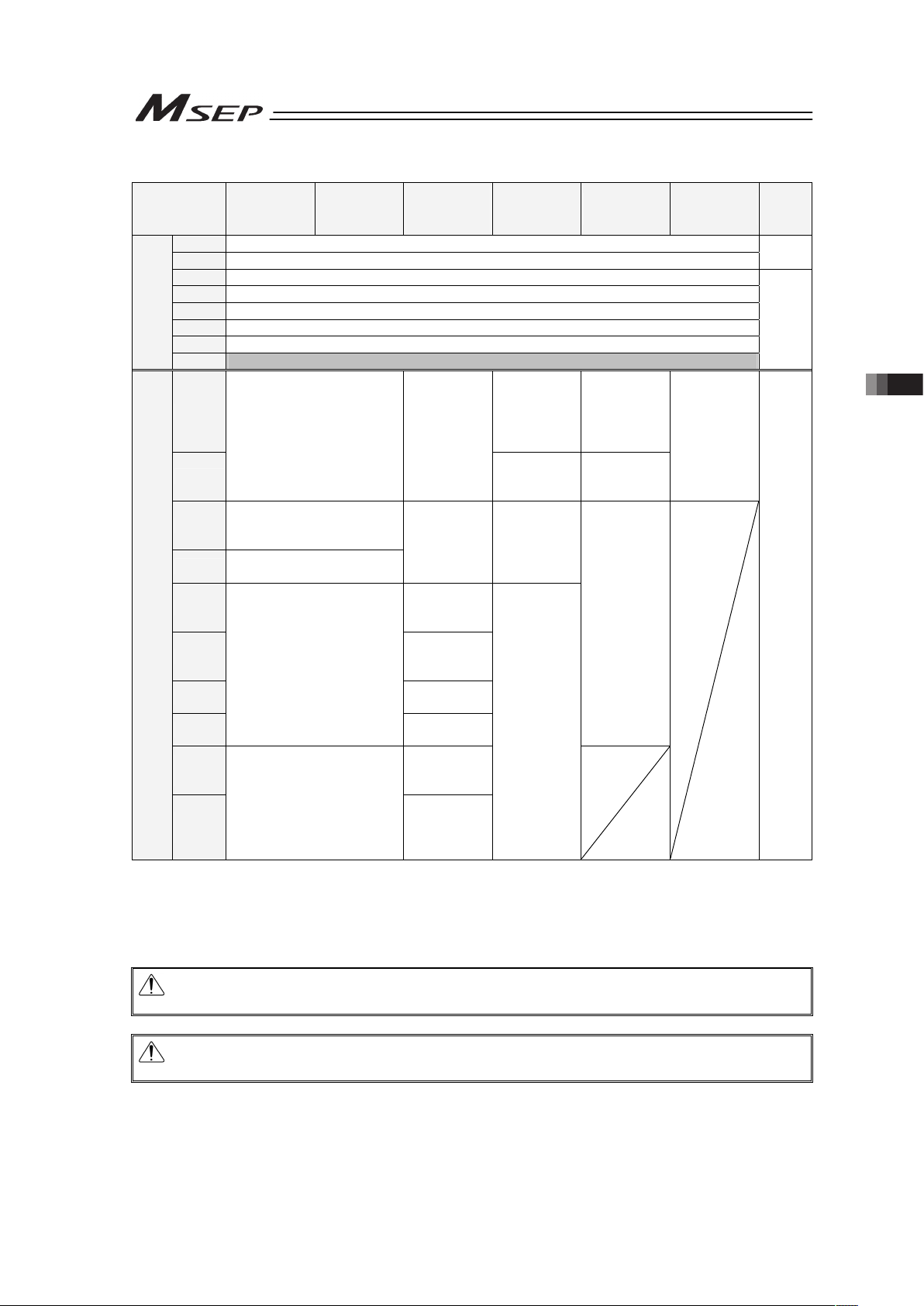
3.4 Fieldbus Type Address Map
91
• MSEP Output ĺ PLC Input (n is PLC input top word address from MSEP)
(Note 1)
PLC Intput
Area
Simple Direct
Mode
Positioner 1
Mode
Direct
Indication
Mode
Positioner 2
Mode
Positioner 3
Mode
SEP I/O
Mode
(Note 2)
Details
n Gateway Status 0
n+1 Gateway Status 1
3.4.3
n+2 Response Command
n+3 Data 0
n+4 Data 1
n+5 Data 2
n+6 Data 3
MSEP Gateway
Response Area
n+7 Occupied Domain
(Note 3)
3.4.9
n+8
Completed
Position No./
Simple Alarm
ID
(Axis No.0)
Status
Signal/
Completed
Position No.
(Axis No.0)
n+9
Current Position
(Axis No.0)
Current
Position
(Axis No.0)
Status Signal
(Axis No.0)
Assignment
Domain for
Axis No.1
Each axis
output port
number 0 to
4
(Axis No.0 to
7)
n+10
Completed Position No./
Simple Alarm ID
(Axis No.0)
n+11
Status Signal
(Axis No.0)
Command
Current
(Axis No.0)
Assignment
Domain for
Axis No.1
n+12
Current
Speed
(Axis No.0)
n+13
Occupied
Domain
(Axis No.0)
n+14
Alarm Code
(Axis No.0)
n+15
Assignment Domain for
Axis No.1
Status Signal
(Axis No.0)
Assignment
Domain for
Axis No.2 to
7
n+16 to
n+23
Assignment
Domain for
Axis No.1
Connected Axes Response Area
n+24 to
n+71
Assignment Domain for
Axis No.2 and later
Assignment
Domain for
Axis No.2
and later
Assignment
Domain for
Axis No.2
and later
3.4.4
to
3.4.8
Note 1 For CC-Link, n and n+1 are for input and output bit addresses, and n+8 is for the top
address of data register.
Note 2 SEP I/O Mode occupies 10 words no matter how many axes are connected.
Note 3 This is the domain occupied unconditionally. Therefore, this domain cannot be used for any
other purpose.
Caution: The mode can be selected for each slot, however, SEP I/O Mode cannot used
together with other modes.
Caution: For MECHATROLINK and CompoNet, only Positioner 3 Mode and SEP I/O Mode
are available for selection.
Page 100
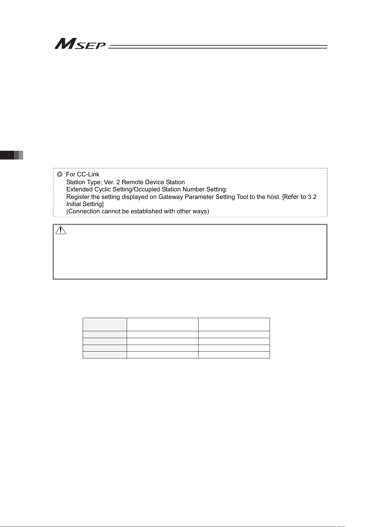
3.4 Fieldbus Type Address Map
92
3.4.2 Example for each Fieldbus Address Map
Shown below is an example for the address map by the combination of operation modes for
each Fieldbus.
Refer to it for the address assignment.
The examples for the address map constructions shown below are provided for each field
network, however is described together
(Note)
for the networks of the same address assignment.
Note Order of address maps for each field network
1) DeviceNet and CompoNet
(Note 1)
2) CC-Link
3) PROFIBUS, EtherNet/IP, MECHATROLINK
(Note 1)
, EtherCAT
Note 1 For MECHATROLINK and CompoNet, only Positioner 3 Mode and SEP I/O
Mode are available for selection.
٧ For CC-Link
Station Type: Ver. 2 Remote Device Station
Extended Cyclic Setting/Occupied Station Number Setting:
Register the setting displayed on Gateway Parameter Setting Tool to the host. [Refer to 3.2
Initial Setting]
(Connection cannot be established with other ways)
Caution:
• If SEP I/O Mode is selected, all the axes connected to MSEP are involved in SEP I/O Mode.
• This controller is able to control 2 axes with one driver board (1 slot), however, different
operation mode cannot be selected in the same driver board.
Example Set the 1st axis in Slot 1 to Positioner 1 Mode and 2nd to Simple Direct Mode
• Even if only one axis is used in the two axes on the same slot, it requires the address space
for 2 axes.
[1] Address Map with Combination of Simple Direct Mode and Direct Indication Mode
In the table below, shows the address map when eight axes of MSEP are operated with a
combination of Simple Direct Mode and Direct Indication Mode in four types of construction for
each Fieldbus as an example.
Combination
Example
Number of Simple Direct
Mode Axes
Number of Direct Indication
Mode Axes
1 8 0
2 6 2
3 2 6
4 0 8
 Loading...