

Page 1

MSCON Controller
Instruction Manual First Edition
Page 2

Page 3

[Important]
x This Instruction Manual is original.
x The product cannot be operated in any way unless expressly specified in this Instruction Manual.
IAI shall assume no responsibility for the outcome of any operation not specified herein.
x Information contained in this Instruction Manual is subject to change without notice for the
purpose of product improvement.
x If you have any question or comment regarding the content of this manual, please contact the
IAI sales office near you.
x Using or copying all or part of this Instruction Manual without permission is prohibited.
x The company names, names of products and trademarks of each company shown in the
sentences are registered trademarks.
x DeviceNet is a registered mark of ODVA.
x CC-Link is a registered mark of Mitsubishi Electric Corporation.
x PROFIBUS is a registered mark of SIEMENS.
x CompoNet is a registered trademark of OMRON Corporation.
x MECHATROLINK is a registered trademark of MECHATROLINK Members Association.
x EtherCAT® is a registered mark of Beckoff Automation GmbH.
x EtherNet/IP is a trademark used under the license of ODVA.
Please Read Before Use
Thank you for purchasing our product.
This Instruction Manual describes all necessary information items to operate this product safely
such as the operation procedure, structure and maintenance procedure.
Before the operation, read this manual carefully and fully understand it to operate this product safely.
The enclosed CD or DVD in this product package includes the Instruction Manual for this product.
For the operation of this product, print out the necessary sections in the Instruction Manual or
display them using the personal computer.
After reading through this manual, keep this Instruction Manual at hand so that the operator of this
product can read it whenever necessary.
Page 4

Page 5

Contents
Safety Guide ·····················································································································1
Precautions in Operation ·································································································· 8
International Standards Compliances············································································· 11
Name for Each Parts and Their Functions······································································ 13
Actuator Axes··················································································································17
Starting Procedures ········································································································ 19
Chapter 1 Specifications Check······················································································ 21
1.1 Product Check ············································································································ 21
1.1.1 Parts····················································································································· 21
1.1.2 Teaching Tool ·······································································································21
1.1.3 Instruction Manuals related to this product,
which are contained in the DVD. ······························································ 22
1.1.4 How to read the model plate················································································ 22
1.1.5 How to read the model·························································································23
1.2 Basic Specifications ···································································································· 24
1.3 Selection of Power Source and Power Supply Supportive Devices··························· 26
1.3.1 Power Capacity and Heat Generation ·······························································26
1.3.2 Selection of Circuit Breaker ················································································· 26
1.3.3 Selection of Leak Current Breaker ······································································27
1.3.4 Control Power (24V DC) Capacity······································································· 27
1.4 Specifications for each Fieldbus ·················································································28
1.4.1 Specifications of DeviceNet Interface·································································· 28
1.4.2 Specifications of CC-Link Interface······································································28
1.4.3 Specifications of PROFIBUS-DP Interface·························································· 29
1.4.4 Specifications of CompoNet Interface ·································································29
1.4.5 Specifications of MECHATROLINK II Interface ··················································· 30
1.4.6 Specifications of EtherNet/IP Interface································································ 30
1.4.7 Specifications of EtherCAT Interface ··································································· 30
1.5 External Dimensions··································································································· 31
1.5.1 Incremental Type ·································································································31
1.5.2 Absolute Type ······································································································32
1.6 Option·························································································································· 33
1.6.1 Regenerative Resistor Unit·················································································· 33
1.7 Installation and Storage Environment ········································································· 35
1.8 Noise Elimination and Mounting Method ····································································36
Chapter 2 Wiring·············································································································39
2.1 Wiring Diagram (Connection of construction devices)················································39
2.2 Circuit Diagram ··········································································································· 39
2.3 Wiring Method·············································································································47
2.3.1 Wiring of Control Power Supply and Drive Power Supply Input Connector ········ 47
2.3.2 Wiring Layout of System I/O Connector ······························································49
2.3.3 Actuator Connection ···························································································· 50
2.3.4 Battery Connection (For Absolute Type)······························································ 52
2.3.5 Connection of Regenerative Resistance Unit······················································ 53
2.3.6 Connection of SIO Connector··············································································55
2.3.7 Wiring Layout of Field Network Connector·························································· 56
Page 6

Chapter 3 Operation ······································································································· 61
3.1 Basic Operation ·········································································································· 61
3.1.1 Basic Operation Methods ···················································································· 61
3.1.2 Parameter Settings······························································································ 65
3.2 Initial Setting ··············································································································· 66
3.3 Setting of Position Data ······························································································71
3.4 Fieldbus Type Address Map························································································ 77
3.4.1 PLC Address Construction by each Operation Mode··········································77
3.4.2 Example for Address Map Construction for each Field Network························· 80
3.4.3 Gateway Control Signals (in common for all operation modes)·························· 90
3.4.4 Control Signals for Direct Simple Direct ······························································93
3.4.5 Control Signals for Positioner 1 Mode································································· 98
3.4.6 Control Signals for Direct Indication Mode ························································103
3.4.7 Control Signals for Direct Indication Mode 2 ····················································· 110
3.4.8 Control Signals for Positioner 2 Mode······························································· 117
3.4.9 Control Signals for Positioner 3 Mode·······························································121
3.4.10 Control Signals for Remote I/O Mode································································ 124
3.4.11 About Commands (Position Data Read/Write and Alarm Axis Read) ··············· 128
3.5 Input and Output Signal Process for Field Network··················································143
3.6 Power Supply and Cutoff ·························································································· 145
3.7 Control and functions of Input and output signals of Modes
other than Remote I/O Mode······ 147
3.8 Control and functions of Input and output signals of Remote I/O Mode··················· 169
3.8.1 Operation Supportive Signal = Patterns 0 to 2, 4 and 5 in common ················· 169
3.8.2 Operation with the Position No. Input = Operations of PIO Patterns 0 to 2········· 177
3.8.3 Direct Position Specification (Solenoid Valve Mode 1)
= Operation of PIO Pattern 4 ········197
3.8.4 Direct Position Specification (Solenoid Valve Mode 2)
= Operation of PIO Pattern 5 ········209
3.9 About Gateway Parameter Setting Tool····································································217
3.9.1 Startup of Tool···································································································· 217
3.9.2 Explanation of each Menu ················································································· 218
3.9.3 Description of Functions ···················································································· 220
3.9.4 Operation Mode Setting·····················································································226
3.10 Field network status LEDs ························································································227
3.10.1 DeviceNet ··········································································································227
3.10.2 CC-Link·············································································································· 227
3.10.3 PROFIBUS ········································································································228
3.10.4 CompoNet··········································································································228
3.10.5 Mechatrolink ······································································································229
3.10.6 EtherNet/IP ········································································································229
3.10.7 EtherCAT ··········································································································· 230
3.11 Gateway status LED ·································································································231
Chapter 4 Vibration Suppress Control Function ···························································233
4.1 Setting Procedure ····································································································· 235
4.2 Settings of Parameters for Vibration Suppress Control············································236
4.3 Setting of Position Data ····························································································237
Chapter 5 Power Saving Function (Automatic Servo-off Function) ······························239
Page 7

Chapter 6 Absolute Reset and Absolute Battery ··························································241
6.1 Absolute Reset··········································································································241
6.2 Absolute Battery········································································································243
6.2.1 Absolute encoder backup specifications ··························································· 243
6.2.2 Replacement of absolute battery······································································· 245
Chapter 7 Parameter ···································································································· 247
7.1 Parameter List···········································································································248
7.2 Detail Explanation of Parameters ·············································································253
7.3 Servo Adjustment······································································································280
Chapter 8 Troubleshooting ··························································································· 283
8.1 Action to Be Taken upon Occurrence of Problem····················································· 283
8.2 Fault Diagnosis ········································································································· 285
8.2.1 Impossible operation of controller······································································285
8.2.2 Positioning and speed of poor precision (incorrect operation) ·························· 286
8.2.3 Generation of noise and/or vibration ································································· 287
8.2.4 Impossible Communication ··············································································· 287
8.3 Alarm························································································································· 288
8.3.1 Gateway Alarm Codes ·······················································································288
8.3.2 Alarm Code for Each Axis··················································································290
8.4 Noise Prevention·······································································································301
Chapter 9 Appendix ······································································································ 302
9.1 List of Specifications of Connectable Actuators························································ 302
Chapter 10 Warranty ····································································································347
10.1 Warranty Period········································································································ 347
10.2 Scope of the Warranty ······························································································ 347
10.3 Honoring the Warranty······························································································ 347
10.4 Limited Liability ·········································································································347
10.5 Conditions of Conformance with Applicable Standards
/Regulations, Etc., and Applications·········· 348
10.6 Other Items Excluded from Warranty········································································ 348
Change History ············································································································· 349
Page 8

Page 9

1
Safety Guide
“Safety Guide” has been written to use the machine safely and so prevent personal injury or
property damage beforehand. Make sure to read it before the operation of this product.
Safety Precautions for Our Products
The common safety precautions for the use of any of our robots in each operation.
No.
Operation
Description
Description
1 Model
Selection
Ɣ This product has not been planned and designed for the application
where high level of safety is required, so the guarantee of the protection
of human life is impossible. Accordingly, do not use it in any of the
following applications.
1) Medical equipment used to maintain, control or otherwise affect
human life or physical health.
2) Mechanisms and machinery designed for the purpose of moving or
transporting people (For vehicle, railway facility or air navigation
facility)
3) Important safety parts of machinery (Safety device, etc.)
Ɣ Do not use the product outside the specifications. Failure to do so may
considerably shorten the life of the product.
Ɣ Do not use it in any of the following environments.
1) Location where there is any inflammable gas, inflammable object or
explosive
2) Place with potential exposure to radiation
3) Location with the ambient temperature or relative humidity exceeding
the specification range
4) Location where radiant heat is added from direct sunlight or other
large heat source
5) Location where condensation occurs due to abrupt temperature
changes
6) Location where there is any corrosive gas (sulfuric acid or
hydrochloric acid)
7) Location exposed to significant amount of dust, salt or iron powder
8) Location subject to direct vibration or impact
Ɣ For an actuator used in vertical orientation, select a model which is
equipped with a brake. If selecting a model with no brake, the moving
part may drop when the power is turned OFF and may cause an
accident such as an injury or damage on the work piece.
Page 10

2
No.
Operation
Description
Description
2 Transportation Ɣ When carrying a heavy object, do the work with two or more persons or
utilize equipment such as crane.
Ɣ When the work is carried out with 2 or more persons, make it clear who
is to be the leader and who to be the follower(s) and communicate well
with each other to ensure the safety of the workers.
Ɣ When in transportation, consider well about the positions to hold, weight
and weight balance and pay special attention to the carried object so it
would not get hit or dropped.
Ɣ Transport it using an appropriate transportation measure.
The actuators available for transportation with a crane have eyebolts
attached or there are tapped holes to attach bolts. Follow the
instructions in the instruction manual for each model.
Ɣ Do not step or sit on the package.
Ɣ Do not put any heavy thing that can deform the package, on it.
Ɣ When using a crane capable of 1t or more of weight, have an operator
who has qualifications for crane operation and sling work.
Ɣ When using a crane or equivalent equipments, make sure not to hang a
load that weighs more than the equipment’s capability limit.
Ɣ Use a hook that is suitable for the load. Consider the safety factor of the
hook in such factors as shear strength.
Ɣ Do not get on the load that is hung on a crane.
Ɣ Do not leave a load hung up with a crane.
Ɣ Do not stand under the load that is hung up with a crane.
3 Storage and
Preservation
Ɣ The storage and preservation environment conforms to the installation
environment. However, especially give consideration to the prevention
of condensation.
Ɣ Store the products with a consideration not to fall them over or drop due
to an act of God such as earthquake.
4 Installation
and Start
(1) Installation of Robot Main Body and Controller, etc.
Ɣ Make sure to securely hold and fix the product (including the work part).
A fall, drop or abnormal motion of the product may cause a damage or
injury.
Also, be equipped for a fall-over or drop due to an act of God such as
earthquake.
Ɣ Do not get on or put anything on the product. Failure to do so may cause
an accidental fall, injury or damage to the product due to a drop of
anything, malfunction of the product, performance degradation, or
shortening of its life.
Ɣ When using the product in any of the places specified below, provide a
sufficient shield.
1) Location where electric noise is generated
2) Location where high electrical or magnetic field is present
3) Location with the mains or power lines passing nearby
4) Location where the product may come in contact with water, oil or
chemical droplets
Page 11

3
No.
Operation
Description
Description
(2) Cable Wiring
Ɣ Use our company’s genuine cables for connecting between the actuator
and controller, and for the teaching tool.
Ɣ Do not scratch on the cable. Do not bend it forcibly. Do not pull it. Do not
coil it around. Do not insert it. Do not put any heavy thing on it. Failure to
do so may cause a fire, electric shock or malfunction due to leakage or
continuity error.
Ɣ Perform the wiring for the product, after turning OFF the power to the
unit, so that there is no wiring error.
Ɣ When the direct current power (+24V) is connected, take the great care
of the directions of positive and negative poles. If the connection
direction is not correct, it might cause a fire, product breakdown or
malfunction.
Ɣ Connect the cable connector securely so that there is no disconnection
or looseness. Failure to do so may cause a fire, electric shock or
malfunction of the product.
Ɣ Never cut and/or reconnect the cables supplied with the product for the
purpose of extending or shortening the cable length. Failure to do so
may cause the product to malfunction or cause fire.
4 Installation
and Start
(3) Grounding
Ɣ The grounding operation should be performed to prevent an electric
shock or electrostatic charge, enhance the noise-resistance ability and
control the unnecessary electromagnetic radiation.
Ɣ For the ground terminal on the AC power cable of the controller and the
grounding plate in the control panel, make sure to use a twisted pair
cable with wire thickness 0.5mm
2
(AWG20 or equivalent) or more for
grounding work. For security grounding, it is necessary to select an
appropriate wire thickness suitable for the load. Perform wiring that
satisfies the specifications (electrical equipment technical standards).
Ɣ Perform Class D Grounding (former Class 3 Grounding with ground
resistance 100: or below).
Page 12

4
No.
Operation
Description
Description
4 Installation
and Start
(4) Safety Measures
Ɣ When the work is carried out with 2 or more persons, make it clear who
is to be the leader and who to be the follower(s) and communicate well
with each other to ensure the safety of the workers.
Ɣ When the product is under operation or in the ready mode, take the
safety measures (such as the installation of safety and protection fence)
so that nobody can enter the area within the robot’s movable range.
When the robot under operation is touched, it may result in death or
serious injury.
Ɣ Make sure to install the emergency stop circuit so that the unit can be
stopped immediately in an emergency during the unit operation.
Ɣ Take the safety measure not to start up the unit only with the power
turning ON. Failure to do so may start up the machine suddenly and
cause an injury or damage to the product.
Ɣ Take the safety measure not to start up the machine only with the
emergency stop cancellation or recovery after the power failure. Failure
to do so may result in an electric shock or injury due to unexpected
power input.
Ɣ When the installation or adjustment operation is to be performed, give
clear warnings such as “Under Operation; Do not turn ON the power!”
etc. Sudden power input may cause an electric shock or injury.
Ɣ Take the measure so that the work part is not dropped in power failure or
emergency stop.
Ɣ Wear protection gloves, goggle or safety shoes, as necessary, to secure
safety.
Ɣ Do not insert a finger or object in the openings in the product. Failure to
do so may cause an injury, electric shock, damage to the product or fire.
Ɣ When releasing the brake on a vertically oriented actuator, exercise
precaution not to pinch your hand or damage the work parts with the
actuator dropped by gravity.
5 Teaching Ɣ When the work is carried out with 2 or more persons, make it clear who
is to be the leader and who to be the follower(s) and communicate well
with each other to ensure the safety of the workers.
Ɣ Perform the teaching operation from outside the safety protection fence,
if possible. In the case that the operation is to be performed unavoidably
inside the safety protection fence, prepare the “Stipulations for the
Operation” and make sure that all the workers acknowledge and
understand them well.
Ɣ When the operation is to be performed inside the safety protection
fence, the worker should have an emergency stop switch at hand with
him so that the unit can be stopped any time in an emergency.
Ɣ When the operation is to be performed inside the safety protection
fence, in addition to the workers, arrange a watchman so that the
machine can be stopped any time in an emergency. Also, keep watch on
the operation so that any third person can not operate the switches
carelessly.
Ɣ Place a sign “Under Operation” at the position easy to see.
Ɣ When releasing the brake on a vertically oriented actuator, exercise
precaution not to pinch your hand or damage the work parts with the
actuator dropped by gravity.
* Safety protection Fence : In the case that there is no safety protection
fence, the movable range should be indicated.
Page 13

5
No.
Operation
Description
Description
6 Trial
Operation
Ɣ When the work is carried out with 2 or more persons, make it clear who
is to be the leader and who to be the follower(s) and communicate well
with each other to ensure the safety of the workers.
Ɣ After the teaching or programming operation, perform the check
operation one step by one step and then shift to the automatic
operation.
Ɣ When the check operation is to be performed inside the safety
protection fence, perform the check operation using the previously
specified work procedure like the teaching operation.
Ɣ Make sure to perform the programmed operation check at the safety
speed. Failure to do so may result in an accident due to unexpected
motion caused by a program error, etc.
Ɣ Do not touch the terminal block or any of the various setting switches in
the power ON mode. Failure to do so may result in an electric shock or
malfunction.
7 Automatic
Operation
Ɣ Check before starting the automatic operation or rebooting after
operation stop that there is nobody in the safety protection fence.
Ɣ Before starting automatic operation, make sure that all peripheral
equipment is in an automatic-operation-ready state and there is no
alarm indication.
Ɣ Make sure to operate automatic operation start from outside of the
safety protection fence.
Ɣ In the case that there is any abnormal heating, smoke, offensive smell,
or abnormal noise in the product, immediately stop the machine and
turn OFF the power switch. Failure to do so may result in a fire or
damage to the product.
Ɣ When a power failure occurs, turn OFF the power switch. Failure to do
so may cause an injury or damage to the product, due to a sudden
motion of the product in the recovery operation from the power failure.
Page 14

6
No.
Operation
Description
Description
8 Maintenance
and
Inspection
Ɣ When the work is carried out with 2 or more persons, make it clear who
is to be the leader and who to be the follower(s) and communicate well
with each other to ensure the safety of the workers.
Ɣ Perform the work out of the safety protection fence, if possible. In the
case that the operation is to be performed unavoidably inside the safety
protection fence, prepare the “Stipulations for the Operation” and make
sure that all the workers acknowledge and understand them well.
Ɣ When the work is to be performed inside the safety protection fence,
basically turn OFF the power switch.
Ɣ When the operation is to be performed inside the safety protection
fence, the worker should have an emergency stop switch at hand with
him so that the unit can be stopped any time in an emergency.
Ɣ When the operation is to be performed inside the safety protection
fence, in addition to the workers, arrange a watchman so that the
machine can be stopped any time in an emergency. Also, keep watch on
the operation so that any third person can not operate the switches
carelessly.
Ɣ Place a sign “Under Operation” at the position easy to see.
Ɣ For the grease for the guide or ball screw, use appropriate grease
according to the Instruction Manual for each model.
Ɣ Do not perform the dielectric strength test. Failure to do so may result in
a damage to the product.
Ɣ When releasing the brake on a vertically oriented actuator, exercise
precaution not to pinch your hand or damage the work parts with the
actuator dropped by gravity.
Ɣ The slider or rod may get misaligned OFF the stop position if the servo
is turned OFF. Be careful not to get injured or damaged due to an
unnecessary operation.
Ɣ Pay attention not to lose the cover or untightened screws, and make
sure to put the product back to the original condition after maintenance
and inspection works.
Use in incomplete condition may cause damage to the product or an
injury.
* Safety protection Fence : In the case that there is no safety protection
fence, the movable range should be indicated.
9 Modification
and Dismantle
Ɣ Do not modify, disassemble, assemble or use of maintenance parts not
specified based at your own discretion.
10 Disposal Ɣ When the product becomes no longer usable or necessary, dispose of it
properly as an industrial waste.
Ɣ When removing the actuator for disposal, pay attention to drop of
components when detaching screws.
Ɣ Do not put the product in a fire when disposing of it.
The product may burst or generate toxic gases.
11 Other Ɣ Do not come close to the product or the harnesses if you are a person
who requires a support of medical devices such as a pacemaker. Doing
so may affect the performance of your medical device.
Ɣ See Overseas Specifications Compliance Manual to check whether
complies if necessary.
Ɣ For the handling of actuators and controllers, follow the dedicated
instruction manual of each unit to ensure the safety.
Page 15

7
Alert Indication
The safety precautions are divided into “Danger”, “Warning”, “Caution” and “Notice” according to the
warning level, as follows, and described in the Instruction Manual for each model.
Level Degree of Danger and Damage Symbol
Danger
This indicates an imminently hazardous situation which, if the
product is not handled correctly, will result in death or serious
injury.
Danger
Warning
This indicates a potentially hazardous situation which, if the
product is not handled correctly, could result in death or serious
injury.
Warning
Caution
This indicates a potentially hazardous situation which, if the
product is not handled correctly, may result in minor injury or
property damage.
Caution
Notice
This indicates lower possibility for the injury, but should be kept to
use this product properly.
Notice
Page 16

8
Precautions in Operation
1. Make sure to follow the usage condition, environment and specification range
of the product.
Not doing so may cause a drop of performance or malfunction of the product.
2. Use the following teaching tools.
Use the PC software and the teaching pendant stated in the next clause as applicable for this
controller.
[Refer to 1.1.2 Teaching Tool.]
3. Backup the data to secure for breakdown.
A non-volatile memory is used as the backup memory for this controller. All the registered
position data and parameters are written into this memory and backed-up at the same time.
Therefore, you will not usually lose the data even if the power is shut down. However, make
sure to save the latest data so a quick recovery action can be taken in case when the controller
is broken and needs to be replaced with another one.
How to Save Data
(1) Save the data to CD-R or hard disk with using the PC software
(2) Hard-copy the information of position tables and parameters on paper
4. Set the operation patterns.
To be applied to variety ways of use, this controller corresponds to the control by each fieldbus
and, in addition, it possesses multiple operation (PIO) patterns.
Setting can be established in the parameters. [Refer to Chapter 3 Operation and Chapter 7
Parameter.]
Set the operation pattern setting to the logic that suits to your use after the power is turned ON.
5. The actuators listed below cannot be connected:
1) Actuator with its motor capacity more than 200W
2) Linear Actuator
3) NS-S Type (Nut rotary actuator)
4) RCS2-SRA7BD
5) Slim Small ROBO Cylinder
(RCS2-RN5N/RP5N/GS5N/GD5N/SD5N/TCA5N/TWA5N/TFA5N)
6) When the total of the motor capacity of the connected actuators exceeds 900W for 200V
motor power or 450W for 100V type
6. Clock setting in calendar function
There may be a case that Gateway Error Code 84A “Real Time Clock Vibration Stop Detect” is
issued at the first time to turn the power ON after the product is delivered. In such a case, set
the current time with a teaching tool.
If the battery is fully charged, the clock data is retained for approximately 10 days after the
power is turned OFF.
Even though the time setting is conducted before the product is shipped out, the battery is not
fully charged. Therefore, the clock data may be already lost even in 10 days after the product is
shipped out.
Warning: Please note it is very risky when the control sequence and PIO pattern setting do not
match to each other. It may not only cause the normal operation disabled, but also
may cause an unexpected operation.
Page 17

9
7. For the rotary actuator, it is necessary to pay attention to cable breakage due to
twisting and other factors.
Especially for the type with a through hole in the center of rotation, and when using it with
cables going through the hole, and also for the actuator with 360q rotation, special care is
required because there is no limit to the rotation in one direction.
8. Limitations on operation of rotary actuator in index mode
Rotary actuators of 360q specification can select the normal mode for finite rotations or the
index mode enabling multi-rotation control by using parameter No.79 “Rotational axis mode
selection”.
[Refer to Chapter 7 Parameter.]
The following limitations are applied to the index mode:
1) Index Mode cannot be selected in the absolute type controllers. It will issue Alarm Code
0A1 “Parameter Data Error”.
2) In the JOG operation by PC software, a teaching pendant or PIO Signal, the indicated
range in one time is from 0 to 360.00q and that makes one turn.
3) Pressing is unavailable. The pressing torque can only be set to 0.
4) Do not issue positioning command around 0q repeatedly during movement near 0°. Failure
to follow this may cause the actuator to rotate in the direction reverse to the specified
rotation direction or operate indefinitely.
5) Soft stroke limit is invalid in the index mode.
9. According to sequence program creation
Please note the following things when creating a sequence program.
When data transfer is necessary between two devices that have a different scan time from each
other, duration more than the longer scan time is required to certainly read the signal. (To have
the loading process on PLC side safely, it is recommended to set the timer to at least twice
longer than the long scanning time.)
䎃
䧎䎃 Operation Image䎃
䎃
䎃
䎃
䎃
䎃
䎃
䎃
䎃
䎃
䎃
䎃
䎃
䎃
䎃
䎃
䎃
䎃
䎃
䎃
䎃
䎃
This controller
(scan time 1msec)
PLC (Programmable Logic Controller)
(example: scan time is 20msec)
Output
Process
Input
Process
As shown in the diagram, the input and output
timings of two devices that have different scan
time do not match, of course, when transferring
a signal.
There is no guarantee that PLC would read the
signal as soon as this controller signal turns
ON.
In such a case, make the setting to read the
signal after a certain time that is longer than the
longer scan time to ensure the reading process
to succeed on the PLC side.
It is the same in the case this controller side
reads the signal.
In such a case, it is recommended to ensure 2
to 4 times of the scan time for the timer setting
margin.
It is risky to have the setting below the scan
time since the timer is also processed in the
scan process.
In the diagram, PLC can only read the input
once in 20msec even though this controller
output once in 1msec.
Because PLC only conducts output process
once in 20msec, this controller identifies the
same out
p
ut status for that while.
Page 18

10
Also, if one tries to read the signal that is being re-written by the other, the signal may be read wrongly.
Make sure to read the signal after the rewriting is complete. (It is recommended to have more than 2 scan
periods to wait.) Make sure not to have the output side to change the output until the other side completes
the reading. Also, a setting is made on the input area not to receive the signal less than a certain time to
prevent a wrong reading of noise. This duration also needs to be considered.
10. PLC Timer Setting
Do not have the PLC timer setting to be done with the minimum setting.
Setting to “1” for 100msec timer turns ON at the timing from 0 to 100msec while 10msec timer
from 0 to 10msec for some PLC.
Therefore, the same process as when the timer is not set is held and may cause a failure such
as the actuator cannot get positioned to the indicated position number in Positioner Mode.
Set “2” as the minimum value for the setting of 10msec timer and when setting to 100msec, use
10msec timer and set to “10”.
Page 19

11
International Standards Compliances
MSCON comply with the following overseas standards.
RoHS Directive CE Marking UL
٤
To be scheduled Compliance not planned
Page 20

12
Page 21

13
Name for Each Parts and Their Functions
No.0
No.1
No.2
No.3
No.4
No.5
16) Absolute Battery Unit
1) Control power
supply
input connector
3) Regenerative
resistor unit
connector
4) Motor power supply
input connector
6) Fan unit
2) Power supply
status LED
5) Screw terminal
for protective
grounding
7) Driver for Axis No.0 and No.1
10) Operation mode
setting switch
13) Gateway
status LED
11) SIO connector
12) System I/O
connector
15) Fieldbus
connector
14) Field network
status LED
8) Driver for Axis No.2 and No.3
9) Driver for Axis No.4 and No.5
Page 22

14
1) Control power supply input connector
[Refer to 2.2 [2] Power Supply Circuit and Brake Circuit]
Supply 24V DC power for control. For an actuator equipped with a brake, also supply 24V DC
power for brake control. (Do not attempt to connect it when there is no actuator with a brake.)
2) Power supply status LED
It shows the status of control power source and driving source.
[Refer to 3.6 Power Supply and Cutoff for the details.]
3) Regenerative resistor unit connector
[Refer to 2.2 [6] Regenerative Resistor Circuit]
This is a connector to plug in the external regenerative unit.
4) Motor power supply input connector
This is a connector to supply power to MSCON.
5) Screw terminal for protective grounding
It is the terminal for the connection of ground cable to prevent electric shock and noise.
It connects to the PE terminal on the motor power supply connector inside MSCON.
6) Fan unit
This is the fan unit to cool down the controller. This unit can be detached from the controller
for maintenance by removing the two screw in the front of the controller.
Page 23

15
7) Actuator driver for Axis No.0 and No.1
8) Actuator driver for Axis No.2 and No.3
9) Actuator driver for Axis No.4 and No.5
One piece of a driver CPU board and one piece of a power stage board make one pair. It is
possible to control two axes with one set. Three classes are available to insert at the
maximum.
Caution: Do not attempt to insert the driver CPU board to position other than the one that
the board was originally inserted to.
The parameter dedicated for the indicated actuator is already written to the driver
CPU board at the purchase order. Proper operation cannot be performed with it
inserted in a wrong position. It is the same for the power stage board. Also, it may
cause such malfunctions as the board being burned down.
Driver
CPU Board
x Brake Release Switch (BK RLS/NOM)
This is a switch to compulsorily release the brake of the actuator
equipped with a brake.
Warning: In normal operation, make sure to set this
switch to NOM side. The brake would not work
even with the servo OFF condition if the switch
is on the RLS side. In the vertical type, the
work may drop and cause an injury or the work
to be damaged.
x Encoder Connector (PG)
It is the connector to connect the actuator encoder cable.
[Refer to Section 2.4.3 Actuator Connection for the details of
how to connect.]
x Motor Cable Connector (M)
It is the connector to connect the actuator motor cable.
[Refer to Section 2.4.3 Actuator Connection for the details of
how to connect.]
x Absolute Battery Connector
Connect an absolute battery if absolute type.
x Driver Status LED
These show the current condition of the drivers.
Upper one shows the status of even axis numbers (0, 2 and 4),
and lower shows the status of odd axis numbers (1, 3 and 5).
Note: The axis number is determined by the slot the driver
board is inserted.
{: Illuminating, ×: OFF, : Flashing
LED (SV*/ALM*)
*: Axis No. = 0 to 5
Lamp status Color
Driver status
{ Green Servo ON
Green During automatic servo OFF
× – Servo OFF
{ Red
Alarm generated, Emergency-stop input,
Motor driving power OFF
Power
Stage
Board
Brake for
even axis
numbers
Brake for
odd axis
numbers
Page 24

16
10) Operation mode setting switch
This is a switch to change the operation mode between Automatic Operation (AUTO) and
Manual Operation (MANU). The operation modes are provided to avoid the duplication of
the operation using PC software or a teaching pendant (described as teaching tool from
now on) and the operation with Fieldbus.
For the details of the mode selection, refer to 12) System I/O connector.
11) SIO connector
This is a connector dedicated for the teaching tool connection.
12) System I/O connector
This is a connector for additional devices for the input of all-axes external emergency stop
and AUTO/MANU switchover.
It is connected in a series with the operation mode setting switch (AUTO/MANU) on the
front panel. The controller can be in the following modes by the mode selection on each
switch and teaching tool.
Condition
MSCON
status
Switch on front panel
Operation mode switchover input
Note 1
AUTO AUTO Short-circuit A/M- and A/M+
AUTO Open A/M- and A/M+ terminals
MANU
MANU Short-circuit A/M- and A/M+
Note 1: Refer to Sections 2.2 [3] Emergency Circuit and 2.2 [7] Mode Switchover Circuit
for the details.
13) Gateway status LED
Gateway condition (status) is displayed.
[Refer to 3.11 Gateway status LED for the details.]
14), 15) Field network connector and field network status LED
Connect the field network cable to connector. [Refer to 2.2 [8] Wiring for Field Network
for details.]
Field network status LEDs show the status (condition) of the fieldbus.
[Refer to 3.10 Field network status LEDs for the details.]
16) Absolute Battery Unit [Refer to Chapter 6.]
If the actuator is the absolute encoder type, set one unit of this battery unit per unit of
actuator to the base frame on the bottom of MSCON, and connect it to the battery
connector
(Note)
on the driver board.
Note : There is an indication of axis number to the battery connectors. Connect Absolute
Battery Unit to the battery connector of the axis number that an absolute encoder
type actuator is connected. [Refer to 2.4.4 Battery Connection.]
Caution: When in MANU Mode of the teaching tool, select “PIO startup prohibited” for the
operation mode.
Page 25

17
Actuator Axes
Refer to the pictures below for the actuator axes that can be controlled.
0 defines the home position, and items in ( ) are for the home-reversed type (option).
Caution: There are some actuators that are not applicable to the origin reversed type. Check
further on the catalog or the Instruction Manual of the actuator.
(1) Rod Type
(2) Slider Type
(3) Flat Type
(4) Arm Type
Page 26

18
300°0°
-
+
+
(5) Gripper Type
(6) Rotary Type
(300q Rotation Specification) (360qRotation Specification)
(360qRotation Specification)
For Multiple Rotation Type with the origin reversed type, the directions of + and – are the other way
around.
Finger Attachment
Page 27

19
Starting Procedures
When using this product for the first time, work while making sure to avoid omission and incorrect
wiring by referring to the procedure below. “PC” stated in this section means “PC software”.
No ψ
ω
ω
No ψ
Contact your local IAI distributor.
ωYes
No ψ
ω
Check Item
Is RDY in Gateway Status LEDs turned ON in green?
Connect the PC software, confirm the alarm code,
and remedy the indicated situation.
Check Item
Is SV* on the status LED display for the driver on the axis
number indicated for the servo-on turned ON in green?
Check of Safety Circuit
Does the emergency stop circuit (drive cutoff circuit) work
properly and turn the servo OFF?
Target Position Setting [Except for simple direct mode and direct numerical specification mode: Chapter 3]
Set a target position in the “Position” field for each position in the position table.
ω
ωYes
Check if there is any problem with the installation of the actuator and the
condition of the actuator use exceeds the ranges of the rated values. Adjust
the servo if necessary.
If an alarm is generated, check the detail of the
alarm on the PC and have an appropriate
treatment.
ωYes
ωYes
Check Item
Any vibration or abnormal noise?
No ψ
Check of Packed Items
Are all the delivered items present?
Installation and Wiring [Refer to 1. and 2.]
Install the controller and actuator and perform wiring according.
Important Check Item
• Is frame ground (FG) connected? • Has the noise countermeasure been taken?
Power Supply and Alarm Check
Connect the PC software, set the operation mode setting switch to “MANU” side and turn the power ON.
Select [Teaching Mode 1 Safety Speed Activated / Prohibit PIO Startup] in the PC software.
Initial Setting and PIO Pattern Select =Refer to 3.2
?
Conduct the initial selection for those such as PIO Patterns for each axis from the PC.
Register the operation mode to MSCON using Gateway Parameter Setting Tool.
Servo ON
Turn the servo ON for all the connected axes by operating the PC.
Check the emergency stop circuit.
Caution
Please perform this process with the actuator away from the mechanical end or interfering objects as much as possible. Move the
actuator away from interfering surroundings.
It may generate an alarm if the actuator hit the mechanical end or interfering objects when
the servo is turned ON.
The slider may get slightly dropped by self-weight if servo ON and OFF is repeatedly performed at the same position. Be careful not to
pinch the hand or damage the work.
No ψ
ωYes
ω
ω
ω
Test Run Adjustment 1
1) Cancel the emergency stop, do not put a work piece on, set to low speed and check the operation with commands from
the PC.
2) Check the operation (of communication) with commands from the host system (PLC, etc.).
Test Run Adjustment 2
Check the system operation conducted.
ω
Establish Link to Field Network
1) Assign MSCON as the host controller [Refer to the instruction manual of the master unit].
2) Put the operation mode setting switch on the front panel of MSCON to AUTO side, and reboot the power.
3) Once the link with the master unit is established, turn ON MON signal in the gateway control signals.
(While MON Signal is ON, control from field network is available.)
Page 28

20
Page 29

21
Chapter 1 Specifications Check
1.1 Product Check
1.1.1 Parts
The standard configuration of this product is comprised of the following parts.
If you find any fault in the contained model or missing parts, contact us or our distributor.
No. Part Name Model Quantity Remarks
1 Controller
Refer to “How to read the model
plate”, “How to read the model”
1
Accessories
2
Control Power Supply
Connector
MC1.5/5-STF-3.81
(Supplier: PHOENIX CONTACT)
1
3
Motor Power Supply
Connector
GMSTB2.5/3-STF-7.62
(Supplier: PHOENIX CONTACT)
1
4 System I/O Connector
FMCD1.5/4-ST-3.5
(Supplier: PHOENIX CONTACT)
1
5
CC-Link Connector
(For CC-Link Type)
SMSTB2.5/5-ST-5.08 AU
(Supplier: PHOENIX CONTACT)
1
6
DeviceNet Connector
(For DeviceNet Type)
SMSTB2.5/5-ST-5.08 AU
(Supplier: PHOENIX CONTACT)
1
7
Absolute Battery Unit
(Absolute Type)
(Battery AB-5) 1
Number of batteries is
determined by the number
of axes to be connected.
8 First Step Guide 1
9 Instruction Manual (DVD) 1
10 Safety Guide 1
1.1.2 Teaching Tool
For the setup operation such as position setting and parameter setting by a teaching, conduct it
on PC software.
Prepare a teaching tool such as PC software and so on for the operations and tunings.
No. Part Name Model
1
PC Software
(Includes RS232C Exchange Adapter + Peripheral Communication
Cable)
RCM-101-MW
2
PC Software
(Includes USB Exchange Adapter + USB Cable + Peripheral
Communication Cable)
RCM-101-USB
3 Teaching Pendant (Touch panel teaching) CON-PTA
4
Teaching Pendant
(Touch panel teaching equipped with a deadman switch)
CON-PDA
5
Teaching Pendant
(Touch panel teaching equipped with a deadman switch + TP adapter
(RCB-LB-TG))
CON-PGA
6 Teaching Pendant CON-T
7
Teaching Pendant (equipped with dead man’s switch + TP adapter
(RCB-LB-TG))
CON-TG
8 Gateway Parameter Setting Tool –
Chapter 1 Specications Check
Page 30

Chapter 1 Specications Check
22
1.1.3 Instruction Manuals related to this product, which are contained in the DVD.
No. Name Manual No.
1 MSCON Controller Instruction Manual ME0304
2
PC software
RCM-101-MW/ RCM-101-USB Instruction Manual
ME0155
3 Touch panel teaching CON-PTA/PDA/PGA Instruction Manual ME0295
4 Teaching Pendant CON-T/TG Instruction Manual ME0178
1.1.4 How to read the model plate
Actuetor Type / SERIAL No.
No. 0
No. 1
No. 2
No. 3
No. 4
No. 5
Connected actuator
type
RCS3-SA6C-I-150-20-500-T2
RCS3-SA6C-I-150-20-500-T2
RCS2-SA6C-I-20-6-200-T2-B
RCS2-SA6C-I-20-6-200-T2-B
RCS2-SA6C-I-20-6-200-T2-B
RCS2-SA6C-I-20-6-200-T2-B
Model
Serial numbe
r
MODEL MSCON-C-6-150I -150I -20I -20I -20I -20I -DV-0-1
SERIAL No. *********
MADE IN JAPAN
Page 31

23
1.1.5 How to read the model
(Example) Consists of 5 axes : Axis No.0, 2, 3 : 60W actuators to be connected
Axis No.4, 5 : 100W actuators to be connected
Axis No.1 : Not connected
MSCON
– C – 5 - 60I–N–60I–60I–100I–100IHA – DV - 0 – 2 –**
<Type Name>
C : Standard Type
<Connected Axes>
1 to 6 : Number of driver axes
<Detail of Connected Axis>
[Motor Type]
12 : 12W Servo Motor
20 : 20W Servo Motor
30D : 30W Servo Motor
30R : 30W Servo Motor (for RS Series)
60 : 60W Servo Motor
100 : 100W Servo Motor
150 : 150W Servo Motor
200 : 200W Servo Motor
N : Not connected (not equipped with motor driver)
[Encoder Type]
I : Incremental
A : Absolute
[Option]
HA : High Accel/Decel Type
L : Home Sensor/Limit Switch Type
C : Creep Sensor Type
B : Brake Type
<Identification for IAI use only>
*There is no identification in some cases
<Power-supply Voltage>
1 : 100V AC
2 : 200V AC
<I/Ocable Length>
0 : No cable
<I/O Type>
DV : DeviceNet Type
CC : CC-Link Type
PR : PROFIBUS-DP Type
CN : CompoNet Type
ML : MECHATROLINK Type
EP : EtherNet/IP Type
EC : EtherCAT Type
A
xis No.
0 1 2 3 4 5
Chapter 1 Specications Check
Page 32

Chapter 1 Specications Check
24
1.2 Basic Specifications
Number of Controlled Axes Max. 6-axis
Control Power Voltage
24V DC r10%
Control Power Current Consumption Max. 2.4A
Add the Control Power In Rush Current
(Note1)
Max. 7A 5msec or less
Driving Source Voltage
100V AC Specification
AC100 to 115V r10%
Drive (Motor)
Power Supply
Voltage
Driving Source Voltage
200V AC Specification
AC200 to 230V r10%
Driving Source Voltage
100V AC Specification
10A max. with 20A for 80msec
(driving source voltage 100V in ambient temp. 25qC)
10A max. with 45A for 80msec
(driving source voltage 115V × 10% in ambient temp. 40qC)
Drive (Motor)
Power Supply
In-Rush Current
(Note1)
Driving Source Voltage
200V AC Specification
10A max. with 45A for 40msec
(driving source voltage 200V in ambient temp. 25qC)
10A max. with 95A for 40msec
(driving source voltage 230V × 10% in ambient temp. 40qC)
Driving Source Voltage
100V AC Specification
Max. 200W/axis (up to 450W in total for six axes)
Motor Capacity of
Connectable
Actuators
Driving Source Voltage
200V AC Specification
Max. 200W/axis (up to 900W in total for six axes)
Electromagnetic Brake Power Supply
Voltage
(when brake-equipped actuator
connected)
24V DC r10%
Brake Power Supply Current Max. 1A/axis (0.5A/axis at steady state)
Brake Power Supply In-Rush Current
(Note1)
Max. 10A 10msec or less
Drive (Motor) Power Capacity Refer to 1.3.1 Power Capacity and Heat Generation.
Leak Current
3.5mA (Motor power supply)
٧ There is no leak current of control power supply and brake power supply.
Heat Generation Refer to 1.3.1 Power Capacity and Heat Generation.
Drive (Motor) Frequency
50/60Hz r5%
Transient Power Cutoff Durability
1msec (Control Power Supply), 20msec (Drive (Motor) Power Supply), 5msec
(Brake Power Supply)
Motor Control System Sinusoidal Wave PWM Vector Current Control
Applicable Encoder Incremental Serial Encoder
Absolute Serial Encoder
Actuator Cable Length Max. 20m
Serial Communication
(SIO Port: For Teaching)
RS485 1ch (complying with Modbus Protocol) Speed : 9.6 to 230.4kbps
External Interface
DeviceNet
(Note)
, CC-Link, PROFIBUS-DP, CompoNet, MECHATROLINK II,
EtherNet/IP, EtherCAT [Refer to Section 1.4. Fieldbus Type]
Data Setting and Input PC software, Teaching pendant, Gateway parameter setting tool
Data Retention Memory
Position data and parameters are saved in the nonvolatile memory.
(There is no limitation in number of writing)
Number of Positioning Points
Max. 256 points (There is no limit for simple direct and direct indication modes)
Note: The number of positioning points differs depending on the operation mode
select by the parameter setting.
LED Indication (Mounted on Front Panel)
LED lamp for driver status display 2 points
Gateway Status LED 5 points
Fieldbus Status LED 2 points
Power Supply Status LED 2 points
Forcibly Releasing of Electromagnetic
Brake
(Mounted on Front Panel)
Switching NOM (standard)/RLS (compulsory release)
Protective Functions Overload, overcurrent, overvoltage, etc.
Protection Function against Electric Shock Class I
Insulation Resistance (Between
secondary power source and FG)
500V DC 10M: or more
Page 33

25
Withstanding Voltage (Between primary
and secondary power sources, Between
primary power source and PE)
1500V AC for 1 min.
(for MSCON individually)
Cooling Method Forced air-cooling
External Dimensions 225W × 154H × 115D
Incremental Type Approx. 1900g
Weight
(when
drivers for
6 axes
mounted)
Absolute Type Approx. 2000g (including batteries)
Surrounding air temperature
0 to 40 qC
Surrounding humidity 85%RH or less (non-condensing)
Surrounding environment [Refer to 1.7 Installation and Storage Environment.]
Surrounding storage
temperature
20 to 70
qC
Note: 0 to 40 qC for absolute battery.
Surrounding storage humidity 85%RH or less (non-condensing)
Usable Altitude 1000m or lower above sea level
Vibration Durability
Frequency 10 to 57Hz/
Swing width: 0.075mm
Frequency 57 to 150Hz/
Acceleration 9.8m/s
2
XYZ Each direction Sweep time: 10 min. Number of sweep: 10 times
Package Drop Dropping height 800mm, 1 corner, 3 edges and 6 surfaces
Protection Class IP20
Pollution Degree II
Environment
Overvoltage Category III
Note1: The rush current value varies depending on the impedance of the power line.
Chapter 1 Specications Check
Page 34

Chapter 1 Specications Check
26
1.3 Selection of Power Source and Power Supply Supportive Devices
1.3.1 Power Capacity and Heat Generation
Shown in the table is the relation between the motor wattage and motor power capacity of an
actuator that can be connected to MSCON.
Actuator Motor
Wattage
Motor Power Capacity
[VA]
Peek Max. Motor
Power Capacity [VA]
Heat Generation [W]
12 41 123 1.7
20 50 150 2.0
30D (
Excluding RS
) 47 141 2.0
30R (for RS) 138 414 4.0
60 146 438 4.8
100 238 714 7.0
150 328 984 8.3
200 421 1263 9.2
RS : Rotary Shaft
1.3.2 Selection of Circuit Breaker
For the selection of the circuit breaker, perform it according to the following items.
• 3 times of the rated current flows to the controller during the acceleration/deceleration. Select an
interrupter that does not trip with this value of current. If a trip occurs, select an interrupter that
possesses the rated current of one grade higher. (Check the operation characteristics curves in
the product catalog.)
• Select an interrupter that does not trip with the in-rush current. (Check the operation
characteristics curves in the product catalog.)
• Consider the current that enables to cutoff the current even when a short circuit current is flown
for the rated cutoff current.
Rated Interrupting Current > Short Circuit Current = Circuit Breaker Primary Power Capacity /
Power Voltage
Consider margin for the rated current on the circuit breaker.
Rated Current for Circuit Interrupter >
Total capacity of motor power for all the connected actuators / AC input voltage
× Safety margin (1.2 to 1.3 for
reference)
Page 35

27
1.3.3 Selection of Leak Current Breaker
• It may be mandatory by law to install a leakage breaker.
• A ground fault circuit interrupter needs to be selected carefully considering the purposes of
prevention of fire and protection of human (Determined by law).
• Leak current varies depending on the capacity of connected motor, cable length and the
surrounding environment. Measure the leak current at the point where a ground fault circuit
interrupter is to be installed when leakage protection is conducted.
• Use the harmonic type (for inverter) for the ground fault circuit interrupter.
1.3.4 Control Power (24V DC) Capacity
Follow the description below for the calculation of 24V DC power capacity.
(1) Control Power Current Consumption :
Select from control power supply current in the table below ·················································· 1)
Number of Controlled
Axes
(Note1)
1 axis 2 axis 3 axis 4 axis 5 axis 6 axis
Control Power Unit
Heating Value [W]
25.5 31.5 38.2 44.2 50.9 56.9
Control Power
Capacity [A]
1.1 1.3 1.6 1.8 2.1 2.4
Note 1: See the line of max. number of controlled axes connectable to corresponding
MSCON.
It can be defined on the manufacturing name plate.
MSCON-C-*-• • • •: “*” is the maximum number of connectable axes.
(2) Current Consumption of Brake Power Supply:
1A or 0.5A
(Note 2)
× number of brake-equipped actuators························································ 2)
Note 2: The maximum current of 1A per actuator runs for approximately 100ms when a brake
is released. The current consumption after the release is 0.5A per unit.
Calculate the capacity with 0.5A per unit when a 24V DC power supply corresponding
to transient load change such as peak load appliance is used and capable for the
maximum current described above. For other cases, calculate with 1A per unit.
(3) Add the Control Power In Rush Current: 7A ·········································································· 3)
[Selection of Power Supply]
Usually, the rated current is to be approximately 1.3 times higher than the total of Control
Power 1) and Motor Power 2) above considering approximately 30% of margin to the load
current. However, considering the inrush currents [excitation (3)], even though it is a short
time, select a power supply with sufficient “peak load capacity”. If a power supply with
insufficient peak capacity is utilized, a transient voltage drop or cutoff may occur. This may
present issues with power supplies providing remote sensing functionality.
(Remark) Selection of Power Supply Protection Circuit Breaker
It is recommended that the power supply protection is conducted on the primary side (AC
power side) of the 24V DC power supply unit.
If having 24V DC turned ON/OFF, keep the 0V connected and have the +24V ON/OFF
(cut one side only).
Be careful to the in-rush current of the 24V DC power supply unit when making a
selection. (Check it in the operation characteristics curve graph in a catalog provided by
the supplier.)
Consider the current that enables to cutoff the current even when a short circuit current is
flown for the rated cutoff current.
y Rated Interrupting Current > Short Circuit Current = Circuit Breaker Primary Power
Capacity / Power Voltage
y (Remark) In-rush Current of IAI Power Supply Unit PS241 = 50 to 60A, 3msec
Chapter 1 Specications Check
Page 36

Chapter 1 Specications Check
28
1.4 Specifications for each Fieldbus
1.4.1 Specifications of DeviceNet Interface
Item Specification
DeviceNet2.0
Group 2 Dedicated Server
Communication Protocol
Network-Powered Insulation Node
Baud Rate Automatically follows the master
Communication System Master-Slave System (Polling)
Number of Occupied
Channels
Refer to 3.4.1 PLC Address Construction by each Operation Mode
Number of Occupied
Nodes
1 Node
Baud Rate Max. Network Length
Total Branch
Line Length
Max. Branch Line
Length
500kbps 100m 39m
250kbps 250m 78m
Communication Cable
Length
(Note2)
125kbps 500m 156m
6m
Communications Cable Use the dedicated cable.
Connector
(Note1)
MSTBA2.5/5-G-5.08-ABGY AU (Manufactured by PHOENIX CONTACT or
equivalent)
Consumption Current of
Communication Power
Supply
60mA
Communication Power
Supply
24V DC (Supplied from DeviceNet)
Note1: The cable-side connector is a standard accessory. (SMSTB2.5/5-ST-5.08 AU by PHOENIX CONTACT)
Note2: For T branch communication, refer to the Instruction Manuals for the master unit and programmable logic
controller (stated as PLC from now on) to be mounted.
1.4.2 Specifications of CC-Link Interface
Item Specification
Communication
Protocol
CC-Link Ver1.1 or Ver2
Station Type Remote device station (4 stations max. to occupy)
Baud Rate 10M/5M/2.5M/625K/156kbps
Communication
System
Broadcast Polling System
Number of
Occupied Stations
Refer to 3.4.1 PLC Address Construction by each Operation Mode
Baud Rate [bps] 10M 5M 2.5M 625k 156k Communication
Cable Length
(Note2)
Total Cable
Length [m]
100 160 400 900 1200
Communications
Cable
Use the dedicated cable.
Connector
(Note1)
MSTBA2.5/5-G-5.08 AU (Manufactured by PHOENIX CONTACT or equivalent)
Note1: The cable-side connector is a standard accessory. (SMSTBA2.5/5-ST-5.08 AU by PHOENIX CONTACT)
Note2: For T branch communication, refer to the Instruction Manuals for the master unit and PLC to be mounted.
Page 37

29
1.4.3 Specifications of PROFIBUS-DP Interface
Item Specification
Communication
Protocol
PROFIBUS-DP
Baud Rate Automatically follows the master
Communication
System
Hybrid System (Master-Slave System or Token Passing System)
Number of
Occupied Stations
Refer to 3.4.1 PLC Address Construction by each Operation Mode
Max. Total Network Length Baud Rate Cable Type
100m 12,000/6,000/3,000kbps
200m 1,500kbps
400m 500kbps
1000m 187.5kbps
Communication
Cable Length
1200m 9.6/19.2/93.75kbps
Type A Cable
Communications
Cable
STP cable AWG18
Connector
(Note1)
9 pin female D-sub Connector
Transmission Path
Format
Bus/Tree/Star
Note 1: Prepare the 9-pin male D-sub connector as the connector on the cable side.
1.4.4 Specifications of CompoNet Interface
Item Specification
Communication System CompoNet specialized protocol
Communication Type Remote I/O Communication
Baud Rate Automatically follows the master
Communication Cable Length Follows CompoNet Type
Slave Type Word Mixed Slave
Available Node Addresses for
Setting
0 to 63 (Setting conducted on controller parameter)
Number of Occupied Channels Refer to 3.4.1 PLC Address Construction by each Operation Mode
Communications cable
(Note1)
Round-type cable (JIS C3306, VCTF2 conductors)
Flat cable I (with no sheathed)
Flat cable II (sheathed)
Connector (Controller side) XW7D-PB4-Rmanufactured by OMRON or equiv.
Note1: Prepare a communication cable separately.
Chapter 1 Specications Check
Page 38

Chapter 1 Specications Check
30
1.4.5 Specifications of MECHATROLINK II Interface
Item Specification
Slave Type Intelligent I/O
Baud Rate MECHATROLINK II 10Mbps
Max. Transmittable Distance 50m
Min. Distance between Stations 0.5m
Number of Occupied Bytes Refer to 3.4.1 PLC Address Construction by each Operation Mode
Transmission Frequency 1 to 8ms
Data Length MECHATROLINK II 32 bytes
Settable Node Address Range 61 to 7F [hex.]
Communications Cable
(Note1)
STP Cable (characteristic impedance 130:)
Connector Controller Side DUSB-ARB82-T11A-FA (Manufactured by DDK or equivalent)
Note1: Prepare the communication cable separately.
1.4.6 Specifications of EtherNet/IP Interface
Item Specification
Communication Protocol IEC61158 (IEEE802.3)
Baud Rate 10BASE-T/100BASE-T (Autonegotiation setting is recommended)
Communication Cable Length
EtherNet/IP Specifications (Distance between hub and each node: 100m or
less)
Number of Connection Master Unit
Available Node Addresses for
Setting
0.0.0.0 to 255.255.255.255
Communications Cable
(Note1)
Category 5e or higher
(Double shielded cable braided with aluminum foil recommended)
Connector RJ45 Connector × 1pc
Note1: Please prepare a communication cable separately.
1.4.7 Specifications of EtherCAT Interface
Item Specification
Communication Protocol IEC61158 type12
Physical Layer 100Base-TX (IEEE802.3)
Baud Rate Automatically follows the master
Communication Cable Length
Depends on EtherCAT® Specification (Distance between each node:
100m or less)
Slave Type I/O slave
Available Node Addresses for
Setting
0 to 127 (17 to 80 : When connected to the master (CJ1W-NC*82)
manufactured by OMRON)
Communications Cable
(Note1)
Category 5e or more
(Double shielded cable braided with aluminum foil recommended)
Connector RJ45 Connector × 2pcs (Input×1, Output×1)
Connection Daisy chain only
Note1: Please prepare a communication cable separately.
Page 39

31
1.5 External Dimensions
1.5.1 Incremental Type
102
204
225
102
99
136
10.510.5
10.5
10.5
5
154
145
4.54.5
4
5
(9)
3-φ5
Front View
10.5
10.5
(77 from DIN rail center)
115
4
Side View
Chapter 1 Specications Check
Page 40

Chapter 1 Specications Check
32
1.5.2 Absolute Type
102
204
225
102
9
9
136
10.5
10.5
10.5
10.5
5
154
145
4.5
4.5
4
5
(9)
(22.3)
3-φ5
Front View
10.5
115
10.5
(77 from DIN rail center)
(134)
4
Side View
Page 41

33
1.6 Option
1.6.1 Regenerative Resistor Unit
This unit is necessary to be connected in the case that the regenerative energy cannot be
consumed by the regenerative resistor built into the MSCON.
[Specification]
Item Specifications
RESU-2
(Screw
Attachment Type)
First Unit
RESUD-2
(DIN Rail
Attachment Type)
MSCON Connection Cable
(Model CB-SC-REU010) 1m enclosed
RESU-1
(Screw
Attachment Type)
Model
2nd unit
or later
RESUD-1
(DIN Rail
Attachment Type)
Regenerative unit connection cable
(Model CB-ST-REU010) 1m enclosed
Dimensions W35.6 × H136 × D115
Body Weight Approx. 0.7kg
Built-in Regeneration Resistor
220: 80W
[Reference for connectable number of units]
Total Wattage for Motors of 6 Axes
Actuator horizontally
oriented
Actuator vertically oriented
No. of Connected
Regenerative Resistance
Units
to 450 to 200 0
to 900 to 600 1
– to 800 2
– to 900 3
Caution : The number of connectable units is a reference for when operation is made
under the following condition;
[Condition] When 1,000mm of back and forth operation is made under the
actuator maximum speed, acceleration/deceleration 0.3G and
rated load with the duty 50%.
In some operational conditions, gateway alarm “0A2 Motor Power Voltage
Error” or “0AB Estimated Regenerative Discharge Power Excess” may be
generated, and it may require more regenerative resistor that described in
the table above. In such cases, add more regenerative resistance units.
However, please note the number of maximum connectable regenerative
resistance units is 4. It is not effective even with connection more than
necessary. Consider to change the operational conditions (to reduce the
load) or to use a higher specification actuator.
Chapter 1 Specications Check
Page 42

Chapter 1 Specications Check
34
[RESU-*Type External Dimensions: Screw Attachment Type]
16.85
17.15
30.7
34
106.5
4.5
1.5
φ
5
1.5
5
4.5
R2.5
145
154
136
[RESUD-*Type External Dimensions: DIN Rail Attachment Type]
φ
5
(77 from DIN rail center)
4.5
4.5
145
154
30.7
34
5
R2.5
4
(9)
136
1.5
1.5
8.5
4
115
Page 43

35
1.7 Installation and Storage Environment
This product is capable for use in the environment of pollution degree 2
*1
or equivalent.
*1 Pollution Degree 2: Environment that may cause non-conductive pollution or transient
conductive pollution by frost (IEC60664-1)
[1] Installation Environment
Do not use this product in the following environment.
• Location where the surrounding air temperature exceeds the range of 0 to 40°C
• Location where condensation occurs due to abrupt temperature changes
• Location where relative humidity exceeds 85%RH
• Location exposed to corrosive gases or combustible gases
• Location exposed to significant amount of dust, salt or iron powder
• Location subject to direct vibration or impact
• Location exposed to direct sunlight
• Location where the product may come in contact with water, oil or chemical droplets
• Environment that blocks the air vent [Refer to 1.8 Noise Elimination and Mounting Method]
When using the product in any of the locations specified below, provide a sufficient shield.
• Location subject to electrostatic noise
• Location where high electrical or magnetic field is present
• Location with the mains or power lines passing nearby
[2] Storage Environment
• Storage environment follows the installation environment. Especially in a long-term storage,
consider to avoid condensation of surrounding air.
Unless specially specified, moisture absorbency protection is not included in the package when
the machine is delivered. In the case that the machine is to be stored in an environment where
dew condensation is anticipated, take the condensation preventive measures from outside of the
entire package, or directly after opening the package.
Chapter 1 Specications Check
Page 44

Chapter 1 Specications Check
36
1.8 Noise Elimination and Mounting Method
(1) Noise Elimination Grounding (Frame Ground)
(2) Precautions regarding wiring method
1) Wire is to be twisted for the power supply.
2) Separate the signal and encoder lines from the power supply and power lines.
(3) Noise Sources and Elimination
Carry out noise elimination measures for electrical devices
on the same power path and in the same equipment. The
following are examples of measures to eliminate noise
sources.
1) AC solenoid valves, magnet switches and relays
[Measure] Install a Surge absorber parallel with the
coil.
2) DC solenoid valves, magnet switches and relays
[Measure] Mount the windings and diodes in parallel.
Select a diode built-in type for the DC
relay.
Earth Terminal
Class D grounding
(Formerly Class-III grounding:
Grounding resistance at 100: or less)
Copper Wire:
Connect to an ground cable with
diameter 1.6mm (2mm
2
: AWG14) or
more.
Connect using FG connection
terminal on the main unit.
MSCON
0V
R
C
+24V
0V+24V
Relay
coil
Relay coil
Surge absorber
Do not share the ground wire with or connect
to other equipment. Ground each controller.
Controller
Other
equipment
Controller
Other
equipment
Other
equipment
Page 45

37
(4) Heat Radiation and Installation
Design and Build the system considering the size of the controller box, location of the controller
and cooling factors to keep the ambient temperature around the controller below 40qC
Pay a special attention to the battery unit since the performance of it would drop both in the low
and high temperatures. Keep it in a room temperature environment as much as possible.
(Approximately 20qC is the recommended temperature.)
To install the unit, use the attachment holes on the top and bottom of the main body and affix
with screws, or attach to DIN rails. (Regenerative resistance unit is separated to screw
attachment type and DIN rail attachment type. Have an appropriate way to affix the unit for
each type.)
20mm or more
50mm or more
20mm
or more
20mm or more
30mm
or more
20mm or more
10mm or more
10mm
or more
50mm or more
150mm or more
Waste
Heat
Chapter 1 Specications Check
Page 46

Chapter 1 Specications Check
38
Page 47
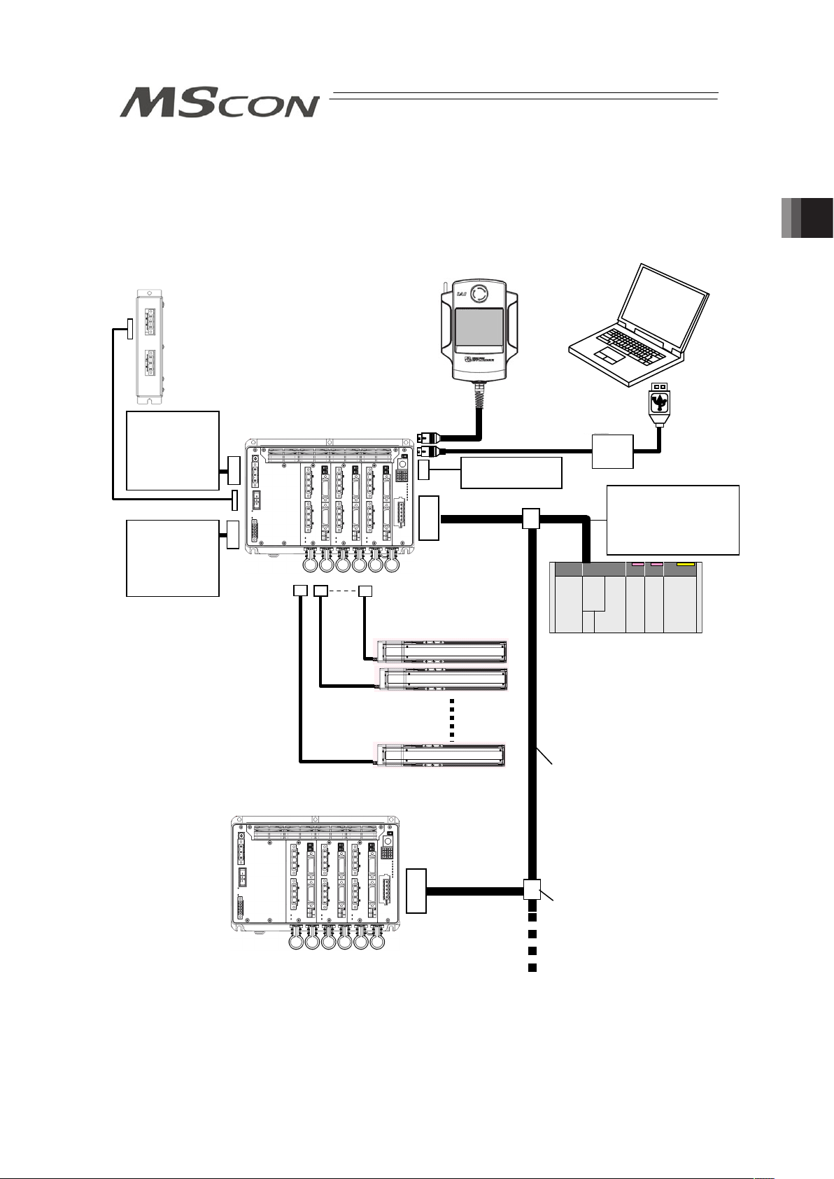
39
Chapter 2 Wiring
2.1 Wiring Diagram (Connection of construction devices)
Teaching Pendant
Touch Panel Teaching
(to be purchased separately)
Host System (Master Unit)
(PLC, etc.…Please prepare separately)
Communication power
supply (if necessary)
(24V DC
Please prepare
se
p
aratel
y)
A
ctuato
r
Emergency Stop
Circuit
PC software
(to be purchased separately)
Regenerative Resistor Unit
Each Fieldbus
communication cable
Follow the specifications of
each Fieldbus for how to
lay out wiring.
Control Power
Supply
(24V DC
Please prepare
separately)
Drive Power
Supply
(100/200V AC
Please prepare
separately)
Chapter 2 Wiring
Page 48

Chapter 2 Wiring
40
2.2 Circuit Diagram
Sample circuit diagrams are shown below.
[1] Drive (Motor) Power Supply Circuit
Note: Drive power supply voltage (100V/200V AC) cannot be changed after the product is
delivered.
L
Circuit
Breaker
Leak Current
Noise
Filter
Surge Absorber
MSCON
L
N
PE
(Earth on either
of them)
Class D grounding
(Formerly Class-III grounding:
Grounding resistance at 100Ω or less)
Motor power supply
connector
Screw terminal for
protective grounding
N
[2] Control Power Supply and Brake Power Supply Circuit
Caution: • When using an actuator equipped with a brake, supply a brake power (24V DC).
With the power not being supplied, 0A5 Electromagnetic Brake Non-Release
Error will occur. Do not attempt to supply a brake power if there is no actuator
with a brake.
• If having the control power supplied/cut on the 24V DC side, keep the 0V
connected and have the +24V supplied/cut (cut one side only). If cut also on 0V
side (cut both sides), it may damage the internal circuit.
Brake Power
Su
pply
Control Power
Supply
FG
24V
+24V
+ -
0V
0V
MSCON
Control Power Supply
Connector
Page 49

41
[3] Emergency Stop Circuit
It is the example of circuit layout when an emergency switch of the teaching pendant is used to
the emergency stop circuit of the equipment.
Note 1: When the teaching pendant is not connected, S1 and S2 become short-circuited
inside the controller.
Note 2: When the motor power must be disconnected externally for safety category
compliance, apply a safety rated contactor between L and N.
Note 3: The rating for the emergency stop signal (EMG-) to turn ON/OFF at contact CR1 is
24V DC and 30mA.
Note 4: For CR1, select the one with coil current 0.1A or less.
+24V
0V
CR1
Emergency
stop reset
switch
Emergency
stop switch
Emergency stop switch
for the teaching pendant
(Note 1)
S1
S2
CR1
(Note 4)
MC1
(Note 1)
MSCON
L
N
+24V
Motor Power Cutoff Relay
Motor power supply
A
C100V
A
C200V
CR1
(Note 3)
MC1
(Note 2)
EMG+
EMG–
MSCON
Second unit
CR1
System I/O Connector
Motor Power Input Connector
System I/O Connector
SIO Connector
SIO Connector
S1
S2
(Note 1)
L
N
+24V
Motor Power Cutoff Relay
A
C100V
A
C200V
CR1
(Note 3)
MC1
(Note 2)
EMG+
EMG–
Motor Power Input Connector
Motor power supply
Chapter 2 Wiring
Page 50

Chapter 2 Wiring
42
[4] Motor • Encoder Circuit
MSCON
Note 1: Applicable Moter Cable types ƑƑƑ: cable length Example) 030 = 3m
Model Name Cable Reference
CB-RCC-MAƑƑƑ-RB Robot cable from 0.5 to 20m
CB-RCC-MAƑƑƑ Standard cable from 0.5 to 20m
CB-X-MAƑƑƑ-RB Robot cable from 0.5 to 20m
For Single Axis Robot
Connection
CB-X-MAƑƑƑ Standard cable from 0.5 to 20m
Note 2: Applicable Encoder Cable types ƑƑƑ: cable length Example) 030 = 3m
Model Name Cable Reference
For Single Axis Robot
Connection
CB-X1-PAƑƑƑ Robot cable from 0.5 to 20m
For Connection of
Single Axis Robot
Equipped with LS
(Option)
CB-X1-PLAƑƑƑ Robot cable from 0.5 to 20m
CB-X3-PAƑƑƑ Robot cable from 0.5 to 20m For RCS2 [models
equipped with LS and
rotary models (RT*) are
excluded]
CB-RCS2-PAƑƑƑ Standard cable from 0.5 to 20m
CB-X2-PLAƑƑƑ Robot cable from 0.5 to 20m RCS2 [for models
equipped with LS and
rotary models (RT*)]
CB-RCS2-PLAƑƑƑ Standard cable from 0.5 to 20m
[5] Absolute Battery Circuit (for Absolute Type Only)
MSCON
BAT*
A
bsolute Battery
Connector
(AX0 to AX5)
Motor
Cable
(Note 1)
Encoder
Cable
(Note 2)
M0 to 5
Motor
Connector
PG0 to 5
Encoder
Connector
Absolute Battery
(AB-5)
Page 51

43
[6] Regenerative Resistance Circuit
MSCON
[7] Mode Switchover (AUTO/MANU) Circuit
When a switchover of the operation modes (AUTO/MANU) is required with an external input,
connect a device such as a switch between A/M + terminal and A/M – terminal.
If not switching externally, apply a jumper on A/M + terminal and A/M – terminal.
A
/M-
A
/M+
System I/O Connector
External
Operation Mode
Setting
(AUTO/MANU)
Switch
ON : AUTO
OFF : MANU
Operation Mode Setting
(AUTO/MANU)
Switch
MANU
A
UTO
24V
5.6K:
Inner
Circuit
MSCON
RB IN
RB OUT
RB IN
RB OUT
Regenerative Resistor Unit
(RESU-2, RESUD-2)
Regenerative Resistor Unit
(RESU-1,RESUD-1)
CB-SC-REU010
CB-ST-REU010
Caution:
Do not attempt to
connect 5 units or
more of the
regenerative
resistance unit.
(4 units at maximum)
RB
Regenerative
Resistor Unit
Connector
Chapter 2 Wiring
Page 52

Chapter 2 Wiring
44
[8] Field Network Circuit (For Field Network Type)
Refer to the instruction manual of the master unit for each field network and constructed PLC
for the details of the circuit.
1) DeviceNet Type
MSCON
DeviceNet Type
V+
Drain
(Shield)
CAN_H
CAN_L
V-
RD
WT
BL
BK
RD
WT
BL
BK
V+
Drain
(Shield)
CAN_H
CAN_L
V+
Drain
(Shield)
CAN_H
CAN_L
V-
RD
WT
BL
BK
Communication power needs to be
supplied by an external device.
Connect the terminal resistor if the unit is
placed at the end of the network.
V-
Terminal Resistance
121
Ω
Terminal Resistance
121
Ω
24V
Power Supply
Class D grounding
(Formerly Class-III grounding : Grounding resistance at 100Ω or less)
Master Unit Slave Device
2) CC-Link Type
MSCON
CC-Link Type
SLD and FG are internally connected.
Connect the terminal resistor if the unit is
placed at the end of the network.
The terminal resistor differs depending on the type
of the dedicated cable for CC-Link.
• Cable FANC-SBH··· 130Ω1/2W
(High Performance Cable
dedicated for CC-Link)
• Cable FANC-SB······ 110Ω1/2W
(CC-Link Dedicated Cable)
Class D grounding
(Formerly Class-III grounding:
Grounding resistance at 100Ω or less)
Master Unit Slave Device
Terminal
Resistance
Terminal
Resistance
3) PROFIBUS-DP Type
MSCON
PROFIBUS Type
Terminal Resistance is required
to be mounted on the terminal.
Master Unit Slave Device
Class D grounding
(Formerly Class-III grounding : Grounding resistance at 100Ω or less)
Page 53

45
4) CompoNet Type
BS+
BDL
BDH
BS-
BS+
BDL
BDH
BS-
BS+
BDL
BDH
BS-
Master Unit Slave Device
Terminal Resistance
121
Ω
MSCON
CompoNet Type
Connect the terminal
resistor if the unit is
placed at the end
of the network.
24V
Power Supply
Supply power separately to the slave devices
that requires the communication power supply.
It is not necessary to supply communication power
to MSCON, however, there is no problem even if
communication power is supplied.
5) EtherNet/IP Type
Master Unit
Switching Hub
Slave Device
EtherNet Straight Cable
Category 5e or more
Double shielded cable braided with aluminum
foil recommended
MSCON
EtherNet/IP Type
Chapter 2 Wiring
Page 54

Chapter 2 Wiring
46
6) MECHATROLINK Type
4
3
2
1
4
3
2
1
4
3
2
1
A4
A3
A2
A1
B4
B3
B2
B1
Master Unit Slave Device
MECHATROLINK
Cable
MECHATROLINK Cable
MSCON
MECHATROLINK Type
Terminal Resistance
JEPMC-W6022
Connect the terminal
resistor if the unit is
placed at the end
of the network.
130
Ω
SH
DATA
/DATA
NC
Connect shield to
connector shell
SH
DATA
/DATA
NC
SH
DATA
/DATA
NC
Connect shield to
connector shell
7) EtherCAT Type
Note: Terminal resistor is not required.
Master Unit
Slave Device
EtherNet Straight Cable
Category 5e or more
Double shielded cable braided with aluminum foil
recommended
MSCON
EtherCAT Type
Page 55

47
2.3 Wiring Method
2.3.1 Wiring of Control Power Supply and Drive Power Supply Input Connector
Insert the wires to the enclosed connector (plug).
Strip the sheath of the applicable wires for 7mm and insert them to the connector. When
inserting, twist the affixing screw on the side of the inlets to the left with a slotted screw driver to
open an inlet. After inserting a cable, twist the affixing screw to the right to hold the cable.
(1) Control Power Supply Input Connector
㩷
㩷
㩷
Power Supply Input
Connector
Model Remarks
Cable Side MC1.5/5-STF-3.81 Enclosed in standard
package
Manufactured by PHOENIX
CONTACT
Controller Side MC1.5/5-GF-3.81
Pin
No.
Signal
Name
Contents Applicable Cable
1 BK PWR+
2 BK PWR-
Brake Power Input
(24V DC ±10%)
KIV0.75mm
2
(AWG19)
3 24V
4 0V
Control Power Input
(24V DC ±10%)
KIV3.5 to 0.75mm2 (AWG 12 to 19)
Select the cable thickness allowable
for the current figured out in the power
capacity.
If supplying power with using a 24V
DC, having it turned ON/OFF, keep the
0V connected and have the +24V
supplied/cut (cut one side only).
5 FG
Functional Ground
Cable
It is connected to the shield of the
encoder connector and fieldbus frame
ground terminal inside the unit.
Front view of
connector on
controller side
Accessory
Connector
(Plug)
BK
PWR
+
-
24V
0V
FG
Chapter 2 Wiring
Page 56

Chapter 2 Wiring
48
(2) Drive (Motor) Power Supply Input Connector
㩷
㩷
㩷
Power Supply Input
Connector
Model Remarks
Cable Side MC2.5/3-STF-7.62 Enclosed in standard
package
Manufactured by
PHOENIX CONTACT
Controller Side MC2.5/3-GF-7.62
Pin No.
Signal
Name
Contents Applicable Cable
1 N
2 L
Motor Power Input
(100V AC or 200V AC …
to be determined when
ordered)
KIV3.5 to 1.25mm2 (AWG12 to16)
Select the cable thickness
allowable for the current figured
out in the power capacity.
3 PE
Functional Ground
Cable
It is connected to the shield of
the encoder connector and
fieldbus frame ground terminal
inside the unit.
Front view of
connector on
controller side
PE
L
N
Page 57

49
2.3.2 Wiring Layout of System I/O Connector
This consists of the emergency stop input and cable terminals for the operation mode
(AUTO/MANU) switch.
Strip the sheath of the applicable wires for 10mm and insert them to the connector. Push a
protrusion beside the cable inlet with a small slotted screwdriver to open the inlet. Once the
cable is inserted, take the slotted screwdriver off the protrusion to fix the cable to the terminal.
㩷
㩷
System I/O
Connector
Model Remarks
Cable Side FMCD1.5/4-ST-3.5 Enclosed in standard
package
Manufactured by PHOENIX
CONTACT
Controller Side MCDN1.5/4-G1-3.5P26THR
Pin
No.
Signal
Name
Contents
Applicable
Cable
1 EMG+ +24V power output for emergency stop
2 S2 For external emergency stop signal input
3 S1 For external emergency stop signal output
4 EMG- Emergency-stop input
5 A/M+
+24V output for operation mode
(AUTO/MANU) switchover
6 A/M-
Operation mode (AUTO/MANU)
switchover signal input
KIV1.25 to
0.2mm
(AWG16 to
24)
7 NC
8 NC
Connection is not required
Accessory
Connector
(Plug)
Emergency Stop
Circuit
Front view of
connector on
controller side
A/M-
A/M+
EMG-
S1
S2
EMG+
Chapter 2 Wiring
Page 58

Chapter 2 Wiring
50
2.3.3 Actuator Connection
To the encoder connector and motor connector on each actuator, connect the relay cables.
[Refer to the Note.]
Check in the instruction manual of each actuator for the details of the relay cables.
(1) Encoder Connector
㩷
Encoder Connector Model Remarks
Cable Side 10126-3000PE
Controller Side 10226-52A2PL
Pin
No.
Signal
Name
Contents Applicable Cable
1 NC
2 NC
3 NC
4 NC
5 NC
6 NC
Unconnected
7 SRD+ Serial Encoder Communication+
8 SRD- Serial Encoder Communication9 LC_SD+
10 LC_SD-
For future extension (Reserved)
11 NC Unconnected
12 24VOUT
13 0V
24V power supply for sensors
14 BATT
15 BATTGND
Battery power supply for ABS
16 VCC
17 GND
Encoder Power Supply
18 LC_VCC
19 LC_GND
For future extension (Reserved)
20 BK21 BK+
Brake Power Supply
22 NC Unconnected
23 RSV Sensor Input (Reserve)
24 OT Sensor Input (Over Travel)
25 CREEP Sensor Input (Creep Sensor)
26 LS Sensor Input (Limit Switch)
Cable dedicated for
IAI products
PG
Front view of
connector on
controller side
Page 59

51
(2) Motor Connector
㩷
㩷
㩷
Motor Connector Model Remarks
Cable Side GIC2.5/4-STF-7.62
Controller Side GIC2.5/4-GF-7.62
Pin No.
Signal
Name
Contents Applicable Cable
1 PE
Protective ground terminal
2 U Motor cable U-phase
3 V Motor cable V-phase
4 W Motor cable W-phase
Cable dedicated for IAI products
Caution: There is an axis number shown on the actuator cables (Encoder Cable: PG0 to 5,
Motor Cable: M0 to 5). Refer to the figure below to plug the actuators correctly. Also,
there are the model code and manufacturing number of the connected actuator
printed on the front panel that you can refer to.
There is a risk of wrong operation or operation out of control of actuators if the
connectors are plugged in to the wrong positions.
Check in the instruction manual of each actuator for the details (connection layout
diagram) of each cable.
If an actuator is purchased individually, there is no axis number written on the
connection cable. Check the actuator model code on the front panel and plug in the
connector.
1st Axis
M0 PG0
2nd Axis
M1 PG1
3rd Axis
M2 PG2
4th Axis
M3 PG3
5th Axis
M4 PG4
6th Axis
M5 PG5
Front view of
connector on
controller side
A
xis number,
actuator model
code and
manufacturing
numbe
r
PE
U
V
W
M
Chapter 2 Wiring
Page 60

Chapter 2 Wiring
52
2.3.4 Battery Connection (For Absolute Type)
If the actuator is the absolute type, connect the harness of the absolute battery unit laid on the
bottom of the main unit to the specified absolute battery connector.
㩷
Absolute Battery Connector Model Remarks
Cable Side IL-2S-S3L-(N) Already connected to battery
Controller Side IL-2P-S3FP2-1
Pin
No.
Signal Name
Contents Applicable Cable
1 BAT- Battery Negative Side
2 BAT+ Battery Positive Side
Already connected to
battery (AB-5)
Top:
for Axis No.0
Bottom:
for Axis No.1
Top:
for Axis No.2
Bottom:
for Axis No.3
Top:
for Axis No.4
Bottom:
for Axis No.5
Front view of
connector on
controller side
BAT
Page 61

53
2.3.5 Connection of Regenerative Resistance Unit
Connect the regenerative resistance unit with a cable enclosed with it referring to the figure
below. The cable to connect with MSCON and that to connect each regenerative resistance
unit differ to each other in the model code.
㩷
Regenerative Resistance Unit Connector Model Remarks
Cable Side 1-178128-3
Controller Side 1-178138-5
Pin
No.
Signal Name Contents Applicable Cable
1 RB+ Regenerative Resistance +
2 RB- Regenerative Resistance -
3 PE Protective Ground Terminal
Dedicate cable
enclosed with
regenerative
resistance unit
Refer to the table below to connect the necessary number of units.
Total Wattage for Motors of 6 Axes
Actuator horizontally
oriented
Actuator vertically oriented
No. of Connected
Regenerative Resistance
Units
to 450 to 200 0
to 900 to 600 1
- to 800 2
- to 900 3
Caution : The number of connectable units is a reference for when operation is made
under the following condition;
[Condition] When 1,000mm of back and forth operation is made under the
actuator maximum speed, acceleration/deceleration 0.3G and
rated load with the duty 50%.
In some operational conditions, gateway alarm “0A2 Motor Power Voltage
Error” or “0AB Estimated Regenerative Discharge Power Excess” may be
generated, and it may require more regenerative resistor that described in
the table above. In such cases, add more regenerative resistance units.
However, please note the number of maximum connectable regenerative
resistance units is 4. It is not effective even with connection more than
necessary. Consider to change the operational conditions (to reduce the
load) or to use a higher specification actuator.
1) CB-SC-REU010 2) CB-ST-REU010
(2nd unit or later)
Front view of
connector on
controller side
RB+
RB-
PE
Chapter 2 Wiring
Page 62

Chapter 2 Wiring
54
Connection Cable
1) Regenerative resistance connection cable for SCON (CB-SC-REU010)
Cable length : 1m
Regenerative Resistor
Unit Side
3
1
1
3
Display of Cable Mode Code
Controller Side
KIV
1.0mm
2
(AWG17)
Light Blue
Brown
Green/Yellow
RB+
RBPE
1
2
3
Wiring Color Signal No.
KIV
1.0mm
2
(AWG17)
Light Blue
Brown
Green/Yellow
RB+
RBPE
1
2
3
No. Signal Coler Wiring
2) Regenerative resistance connection cable for XSEL (CB-ST-REU010)
Cable length : 1m
Regenerative Resistor
Unit Side
Regenerative Resistor
Unit Side
3
1
KIV
1.0mm
2
(AWG17)
1
3
Display of Cable Mode Code
Light Blue
Brown
Green/Yellow
RB+
RBPE
1
2
3
Wiring Color Signal No.
KIV
1.0mm
2
(AWG17)
Light Blue
Brown
Green/Yellow
RB+
RBPE
1
2
3
No. Signal Coler Wiring
Page 63

55
2.3.6 Connection of SIO Connector
Connect an applicable teaching tool such as the PC software.
㩷
SIO connector Model Remarks
Cable Side miniDIN 8 Pin
Controller Side TCS7587-0121077
Pin No.
Signal
Name
Contents Applicable Cable
1 SGA Teaching Tool Signal +
2 SGB Teaching Tool Signal 3 5V Power Supply for Teaching Tool
4 ENB Enable Signal Input
5 EMGA Emergency Stop Signal A
6 24V Power Supply for Teaching Tool
7 0V 0V
8 EMGB Emergency Stop Signal B
Shell 0V 0V
Cable dedicated for
IAI products
Chapter 2 Wiring
Page 64

Chapter 2 Wiring
56
2.3.7 Wiring Layout of Field Network Connector
Check the instruction manuals for each Field Network master unit and mounted PLC for the
details.
1) DeviceNet Type
Shield
BL (CAN L)
RD (V+)
WT (CAN H)
BK (V-)
DeviceNet
Connector
Model Remarks
Cable Side SMSTB2.5/5-ST-5.08 AU Enclosed in standard package
Manufactured by PHOENIX
CONTACT
Controller
Side
MSTBA2.5/5-G-5.08 ABGY AU
Pin No. Signal Name Contents Applicable Cable
1 V- (BK)
Power Supply Cable
Negative Side
2 CAN L (BL)
Communication Data Low
Side
3 Shield (None)
Shield
4 CAN H (WT)
Communication Data High
Side
5 V+ (RD)
Power Supply Cable
Positive Side
DeviceNet
Dedicated Cable
(Note): Connect a terminal resistor (121:) between CAN L and CAN H
to the end of the network. [Refer to 2.2 [8] Field Network Circuit
(For Field network Type)]
Blue
Black
Red
White
Front view of
connector on
controller side
Page 65

57
2) CC-Link Type
WT (DB)
BL (DA)
Shield (SLD)
YW (DG)
㩷
CC-Link Connector Model Remarks
Cable Side SMSTB2.5/5-ST-5.08 AU Enclosed in standard
package
Manufactured by PHOENIX
CONTACT
Controller Side MSTBA2.5/5-G-5.08 AU
Pin No.
Signal Name
(Color)
Contents
Applicable
Cable
1 DA (BL) Communications Line A
2 DB (WT) Communications Line B
3 DG (YW) Digital GND
4 SLD
Connect the shield of the shielded
cable (Connect the FG of the 5 pins
and controller FG internally)
5 FG
Frame Ground
(Connect the SLD of the 4 pins and
controller FG internally)
CC-Link
Dedicated
Cable
(Note): Connect a terminal resistor (121:) between DA and DB to the
end of the network. [Refer to 2.2 [8] Field network Circuit (For
Field network Type)]
Front view of
connector on
controller side
DA
DB
SLD
FG
DG
Chapter 2 Wiring
Page 66

Chapter 2 Wiring
58
3) PROFIBUS-DP Type
5 1
9 6
Cable
Shield
Red B line (Positive side)
Use the type A cable for PROFIBUS-DP (EN5017).
Green A line (Negative side)
㩷
PROFIBUS-DP
Connector
Model Remarks
Cable Side D-sub 9-pin connector (Male) Please prepare separately
Controller Side D-sub 9-pin connector (Female)
Pin
No.
Signal Name Contents Applicable Cable
1 NC Unconnected
2 NC Unconnected
3 B-Line
Communications Line B
(RS485)
4 RTS Request for Sending
5 GND Signal GND (Insulated)
6 +5V +5V Output (Insulated)
7 NC Unconnected
8 A-Line
Communications Line A
(RS485)
9 NC Unconnected
PROFIBUS-DP
Dedicated Cable
(Note): Connect a terminal resistor (220:) between A-Line and B-Line to
the end of the network. [Refer to 2.2 [8] Field network Circuit (For
Field network Type)]
1
5
6
9
Front view of
connector on
controller side
Page 67

59
4) CompoNet Type
㩷
㩷
CompoNet Connector Model Remarks
Cable Side
Connector that
complies with
CompoNet standards
Please prepare separately
Controller Side XW7D-PB4-R Manufactured by OMRON
Pin
No.
Signal Name
(Color)
Contents Applicable Cable
1 BS+ (RD)
Communication Power
Supply +
(Note 1)
2 BDH (WT) Signal Cable H Side
3 BDL (BL) Signal Cable L Side
4 BS- (BK)
Communication Power
Supply -
(Note 1)
CompoNet
Dedicated Cable
Note 1: It is unnecessary to supply the communication power. (Internal
power source is used.)
If conducting multi power supply to other slave devices via
communication cables, there is no problem with connecting the
power supply to BS+ and BS- terminals.
(Note): Connect a terminal resistor (121:) between BDH and BDL to
the end of the network. [Refer to 2.2 [8] Field network Circuit
(For Field network Type)]
5) EtherNet/IP Type
㩷
EtherNet/IP Connector Model Remarks
Cable Side 8P8C Modular Plug
Controller Side 8P8C Modular Jack
Pin No.
Signal Name
(Color)
Contents Applicable Cable
1 TD+ Sent data +
2 TD- Sent data 3 RD+ Received data +
4 ʊ Not used
5 ʊ Not used
6 RD- Received data 7 ʊ Not used
8 ʊ Not used
For EtherNet cable,
use a straight STP
cable that
possesses the
performance of
Category 5e or
more.
Front view of
connector on
controller side
1
2
3
4
Front view of
connector on
controller side
BK (BS-)
BL (BDL)
RD (BS+)
WT (BDH)
8
1
Chapter 2 Wiring
Page 68

60
6) MECHATROLINK Type
㩷
MECHATROLINK Connector Model Remarks
Cable Side Connector that
complies with
MECHATROLINK
standards
Controller Side DUSB-ARB82-T11A-FA Manufactured by DDK
Pin
No.
Signal Name
(Color)
Contents Applicable Cable
A1/B1 NC Unconnected
A2/B2
/DATA Signal Cable - Side
A3/B3 DATA Signal Cable + Side
A4/B4 SH Shield
MECHATROLINK
Dedicated Cable
(Note): Connect a terminal resistor (JEPMC-W6022) between DATA and
DATA if the unit comes to the end of the network. [Refer to 2.2 [8]
Field network Circuit (For Field network Type)]
7) EtherCAT Type
㩷
EtherCAT Connector Model Remarks
Cable Side 8P8C Modular Plug
Controller Side 8P8C Modular Jack
Pin No.
Signal Name
(Color)
Contents Applicable Cable
1 TD+ Sent data +
2 TD- Sent data 3 RD+ Received data +
4 ʊ Not used
5 ʊ Not used
6 RD- Received data 7 ʊ Not used
8 ʊ Not used
For EtherNet cable,
use a straight STP
cable that
possesses the
performance of
Category 5e or
more.
Front view of
connector on
controller side
B1
A1
Front view of
connector on
controller side
B4
A4
1
8
1
8
Chapter 2 Wiring
Page 69

61
Chapter 3 Operation
3.1 Basic Operation
3.1.1 Basic Operation Methods
This controller is to be controlled with fieldbus. Even though there are several types for an
actuator, such as slider type, rod type, rotary type, gripper type, etc., the method to control the
operation is the same unless otherwise specified in this manual.
PLC (Master)
Actuator
Controller (Slave)
Transfer data
with Fieldbus
Teaching pendant
Slave
Command target position,
speed, etc.
Confirmation of movement
complete (read status
si
g
nal
)
Slave
Chapter 3 Operation
Page 70

3.1 Basic Operation
62
[Basic Operation Procedures]
[1] Establish the parameter settings on all the connected axes by using a teaching tool such
as the PC software.
1) When using an operation pattern in those described in the next page except for
Remote I/O Mode, set the Parameter No. 25 PIO Pattern to 8. When using
Remote I/O Mode
(Note 1)
, establish the setting in Parameter No. 25 PIO Pattern
considering the suitable operation mode to be used.
[Refer to 3.4.10 Control Signals in Remote I/O Mode.]
Note 1: It is necessary to set all the axes of MSCON to Remote I/O Mode.
2) Set the zone (Parameters No.1 and 2) and soft limit (Parameter No.3 and 4) that
suit to the system.
[Refer to Chapter 7 Parameter Setting]
[2] Initial Setting [Refer to Sections 3.2 and 3.9]
Establish the settings for those such as the slave addresses in the field network using
Gateway Parameter Setting Tool. Establish the settings of the motions for all the axes.
1) Establish the setting following the procedure described in Section 3.2.
2) Set the gateway parameters to suit the system to be used.
Establish such settings as the calendar function (clock setting) use or the speed unit
change in Direct Indication Mode.
[3] Setting of Position Data [Refer to Sections 3.3]
(Note) Setting of Direct Indication Mode is not necessary.
Set the data for those to be used such as target position, speed, etc. to the position data.
[4] Field Network Settings [Refer to Sections 3.4.1 and 3.4.2]
Assign MSCON to PLC (master unit).
[Refer to the instruction manuals for the master unit and PLC]
[5] Link to Network
1) Put the operation mode setting switch on the front panel of MSCON to AUTO side and
reboot the power. (By putting to AUTO, field network line activates.)
2) Once the link to PLC (master unit) is established
(Note 2)
, turn ON MON Signal of the
gateway control signals
(Note 3)
. While MON Signal is ON, control from field network is
available.
Note 2: By referring to 3.10 Field network status LEDs display, confirm that the
communication is established in the normal condition.
Note 3: Refer to 3.4.3 Control Signals of Gateway.
[6] Operation Control in Each Operation Mode [Refer to Sections 3.4.4 to 3.4.10]
1) Send the information of the target position, speed, acceleration/deceleration, etc. from
PLC (master unit) to the MSCON.
2) The actuator follows the received information of the target position, speed,
acceleration/deceleration, etc. to perform a positioning at the specific coordinates.
3) Confirm the status of positioning complete.
Page 71

63
Ɣ Operation Mode Available
7 types of operation modes are available to select from. The settings are to be established
with Gateway Parameter Setting Tool.
Shown below are the outline.
Operation
Pattern
Contents Overview
Positioner 1
In Positioner 1 Mode, 256
points of position data can
be registered at the
maximum and is able to stop
at the registered positions.
Monitoring of the current
position is also available.
Simple Direct
Mode
In Simple Direct Mode, the
target position can be
indicated directly by
inputting a value. Monitoring
of the current position is also
available.
Those other than the target
position are to be indicated
in the position table, and the
setting can be done for 256
points at maximum.
Communication with Fieldbus
Dedicated Cable
100V/200V AC+24V
Target Position
Target Position No.
Control Signal
PLC
Current Position
Completed Position No.
Status Signal
Electric Cylinder
Direct Indication
Mode
Direct Indication 2
Mode
The target position, speed
acceleration/deceleration
and pressing current limit
can be indicated with
inputting a number.
Monitoring of not only the
current position, but also the
current speed and indicated
current are available.
In Direct Indication 2 Mode,
anti-vibration control is
available instead of JOG
operation.
+24V 100V/200V AC
Target Position
Positioning Width
Speed
Acceleration/Deceleration
Push %
Control Signal
PLC
Current Position
Current Value
(Command Value)
Current Speed
(Command Value)
Alarm Code
Status Signal
Communication with Field Network
Dedicated Cable
Electric Cylinder
Position 2 Mode
This is the operation mode
of the position data of 256
points at maximum set in the
position table. The
monitoring of the current
position is not available
This mode is that the
transferred data is reduced
from Positioner 1 Mode.
+24V 100V/200V AC
Target Position No.
Control Signal
PLC
Completed Position No.
Status Signal
Communication with Fieldbus
Dedicated Cable
Electric Cylinder
Position 3 Mode
This is the operation mode
of the position data of 256
points at maximum set in the
position table. The
monitoring of the current
position is not available
This is the mode to control
with the minimized number
of signals to perform the
positioning operation by
reducing the amount of sent
and received data from
Positioner 2 Mode.
+24V 100V/200V AC
Target Position No.
Control Signal
PLC
Completed Position No.
Status Signal
Communication with Fieldbus
Dedicated Cable
Electric Cylinder
3.1 Basic Operation
Page 72

3.1 Basic Operation
64
Operation
Pattern
Contents Overview
Remote I/O
Five types
(Note 1)
of control
same for PIO are available.
Note : It is to be switched
with PIO patterns
(driver board
parameters)
+24V 100V/200V AC
Target Position No.
Control Signal
PLC
Completed Position No.
Status Signal
Communication with Fieldbus
Dedicated Cable
Electric Cylinder
Note 1: Available PIO pattern numbers: 0, 1, 2, 4 and 5
[See 3.4.10 Control Signal for Remote I/O Mode.]
Page 73

65
3.1.2 Parameter Settings
Parameter data should be set appropriately according to the applicaiton requirements.
Parameters are variables to be set to meet the use of the controller in the similar way as
settings of the ringtone and silent mode of a cell phone and settings of clocks and calendars.
(Example)
Software Stroke Limit : Set a proper operation range for definition of the stroke end, prevention
of interferences with peripherals and safety.
Zone Output : Set to require signal outputs in an arbitrary position zone within the
operation zone.
Parameters should be set to meet the use of the controller prior to operation. Once set, they
may not set every operation.
Refer to Chapter 7 for the parameter types and the details.
3.1 Basic Operation
Page 74

3.2 Initial Setting
66
3.2 Initial Setting
The operation mode is to be set using Gateway Parameter Setting Tool (Ver. 1.2.0.0 or later).
Registration of positions and setting of parameters are to be conducted on RC PC
Software
(Note1)
.
Note1: See the instruction manual of the PC software for the applicable version.
Shown below is the process for the setup. Follow the instruction to conduct the setting properly.
(Preparation) Install RC PC Software and Gateway Parameter Setting. For Gateway
Parameter Setting Tool, install the file stored in the CD-ROM for PC software, or
download from our website, intelligentactuator.com.
[Refer to the instruction manual of the PC software for the details of the PC
software.]
Make sure the system I/O connector wires and operation mode setting switch are in MANU
condition when having the setting done.
[Step 1] Join the PC and SIO connector of MSCON with using the cable enclosed in RC PC
Software, and start up RC PC Software. Establish the setting in Parameter No. 25 PIO
Pattern. [Refer to 3.1.1 Selectable Operation Patterns.]
Operation Pattern PIO Pattern Setting
Types other than Remote I/O Mode 8
Remote I/O Mode 0, 1, 2, 4, 5 (select number referring to
Section 3.4.10)
[Step 2] Close RC PC Software and open Gateway Parameter Setting Tool.
The following window appears. Select “MSCON” GW and click OK.
[Step 3] Once MSCON is detected the detected unit numbers become available to select. Select
the unit number to be connected and click the OK button.
MSCON being detected Select the unit number to be connected
Page 75

67
[Step 4] The main window opens. The main window opens even when MSCON could not be
detected.
Main windows (Initial condition)
[Step 5] Reading is started from MSCON to PC. Click on the Read button and a confirmation
window appears. Click on the “Yes” button.
If the writing is finished in normal condition, writing complete window appears. Click
OK.
3.2 Initial Setting
Page 76

3.2 Initial Setting
68
[Step 6] The parameters input to MSCON are listed as shown below. Indicate the Field Network
node addresses in Address.
Caution
In the following slave, set the value the number of occupied station is
added to the current station number.
[Step 7] Select whether to use Remote I/O Mode or any other mode (such as Positioner Mode).
When Remote I/O Mode is selected, any other mode except for Remote I/O Mode
cannot be selected for all the axes on MSCON.
Page 77

69
[Step 8] Select an operation mode for each drive unit (in 2 axes unit).
Select an operation mode for Drive Unit 0 (AX0: 1st axis, AX1: 2nd axis) first. (Only
Remote I/O Mode can be selected if Remote I/O Mode was selected in Step 7.)
[Step 9] For MSCON with the number of driver axes 3 or more, select the operation mode of
Drive Unit 1 (AX2: 3rd axis, AX3: 4th axis).
(Note) By selecting the operation mode for Drive Unit 0 [Refer to Step 8], the
operation mode for Drive Unit 1 becomes available to be selected.
[Step 10] For MSCON with the number of driver axes 5 or more, select the operation mode of
Drive Unit 2 (AX4: 5th axis, AX5: 6th axis).
(Note) By selecting the operation mode for Drive Unit 1 [Refer to Step 9], the
operation mode for Drive Unit 2 becomes available to be selected.
[Step 11] In case there is an actuator that is connected but not to be activated (reserved axis),
tick on “Axis n Reserved” beside the operation mode setting box for each drive unit. (n
indicate the axis number)
(Note) An error will be issued if an actuator is not connected.
Caution: If set as the reserved axis, but an actuator not to be connected, set as the
invalid axis in Parameter No. 158 Invalid Axis Setting.
Even if the total number of the used axes is an odd number, make the last
axis in reservation to get an even number. It is necessary to secure as much
area as when not set as reserved even if set as the reserved axis.
[Step 12] Conduct only for EtherNet/IP Type (move onto Step 13 if not applied)
Click on Setting in the menu and select EtherNet/IP Setting, and the setting window for
the IP address, subnet mask and default gateway opens. Establish the settings to suit
your system.
3.2 Initial Setting
Page 78

70
[Step 13] Write the edited operation mode setting parameters to MSCON. Click on the “Transfer”
button shown below and a confirmation window pops up. Click on the “Yes” button.
If the writing is finished in normal condition, writing complete window appears. Click
OK.
[Step 14] A confirmation window for Gateway Unit reboot opens. Click “Yes” to accept the reboot.
[Step 15] After rebooting, a confirmation window for parameter reading appears for confirmation
of the written contents. Click “Yes” to accept the reading.
Once the reading process is complete, confirm that the written contents are reflected.
If not written properly, do the process again from Step 2.
Reference: The settings are conducted in the special parameters for the process
of communication error, change in pressing method for Fieldbus Type
and speed unit change for Direct Indication Mode. Refer to 3.9. About
Gateway Parameter Setting Tool for the details.
3.2 Initial Setting
Page 79

71
3.3 Setting of Position Data
The values in the position table can be set as shown below. In the case that only positioning is
necessary, all you have to do is to input the position data, and nothing else is required as long
as the indication of acceleration and deceleration is needed. For the speed and
acceleration/deceleration, the data set to the parameters is automatically reflected to the
setting. Therefore, the work can be simple if you put the speed and acceleration/deceleration
data to the parameter setting.
1) 2) 3) 4) 5) 6) 7) 8) 9) 10) 11) 12) 13) 14) 15)
No.
Position
[mm]
Velocity
[mm/s]
Accele-
ration
[G]
Decele-
ration
[G]
Pressing
[%]
Thresh-
old
[%]
Positioning
width
[mm]
Zone+
[mm]
Zone-
[mm]
Acceleration/
Deceleration
mode
Incre-
mental
Gain
set
Stop
mode
Vibration
suppress
No.
Comment
0 0.00 100.00 0.30 0.30 0.00 0.00 0.10 0.00 0.00 0 0 0 0 0
1 100.00 100.00 0.30 0.30 0.00 0.00 0.10 0.00 0.00 0 0 0 0 0
2 150.00 200.00 0.30 0.30 50.00 0.00 30.00 0.00 0.00 0 0 0 0 0
3 200.00 400.00 1.00 1.00 0.00 0.00 0.10 0.00 0.00 0 0 0 0 1
4 200.00 200.00 0.30 0.30 0.00 0.00 0.10 250.00 230.00 0 0 0 0 2
5 500.00 50.00 0.10 0.10 0.00 0.00 0.10 0.00 0.00 0 0 0 0 0
6
7
Caution: The input value is treated as the angle for the rotary actuator.
Therefore;
[mm]ĺ[deg] ············· 1.2=1.2deg
[mm/s]ĺ[deg/s]········ 100=100deg/s
They are treated as above.
Please note that the display on the screen of a teaching tool such as the
PC software is in [mm].
1) Position No.········· It is the number commanded by PLC in operation command.
Caution: Do not use position No.0 if available positions remains enough.
At the first servo ON after power ON, the completed position No. output is
0 even if the actuator is not located at position No.0. The actuator enters
into the same state as that at positioning to position No.0. The completed
position No. output is 0 during movement of the actuator. To use position
No.0, get the command history by using the sequence program to check
completed position No.0 based on the history.
2) Position [mm] ······ Positioning coordinate value. Enter it as the distance from the home
position.
For pitch feed (relative movement = incremental feed), enter the pitch
width.
A value with – indicates that the actuator moves toward the home
position. A value without – indicates that the actuator moves to be away
from the home position.
Caution: (1) In the case of a Gripper Type:
Set the coordinate value on the single finger basis. Set the value for
the movement of one finger from the home position. Stroke
information in the specification is shown in the total value of
movement distance of the two fingers.
Therefore, the stroke is 1/2 of what is described in the specifications.
(2) In the case of a Rotary Type
Set the coordinate value by an angle from the home.
3.3 Setting of Position Data
Page 80

3.3 Setting of Position Data
72
3) Velocity [mm/s]···· Set the velocity in the operation.
Do not attempt to input a value more than the maximum velocity or less
than the minimum velocity
*1
.
*1 Minimum velocity [mm/sec] =
Lead length [mm] / Number of encoder pulse / 0.001 [sec]
4) Acceleration [G] ·· Set the acceleration at start.
5) Deceleration [G] ·· Set the deceleration at stop.
(Reference) How to set the acceleration is described below The same idea
can be applied to the deceleration.
1G=9800mm/s
2
: Acceleration capable to accelerate up to
9800mm/s per second
0.3G : Acceleration capable to accelerate up to 9800mm/s × 0.3
= 2940mm/s per second
Caution: (1) Set the velocity, acceleration and deceleration so that they do not
exceed the rating values described in the brochure or the catalog or
instruction manual of the actuator. The setting that exceeds the rated
acceleration/deceleration speed may shorten the actuator life
remarkably.
(2) Consider to lower the acceleration/deceleration speed when a shock
or vibration is applied to the actuator or work. In such cases, do not
continue the use of the actuator, otherwise the product life may be
shortened extremely fast.
(3) If the payload is extremely lighter than the rated payload, increase
acceleration/deceleration to larger than their rated values to shorten
the tact time. Contact our company. Inform us of the weight, shape and
mounting method of the work and the installation conditions of the
actuator.
(4) For the gripper type, have the setting done for the speed and
acceleration/deceleration in the basis of one finger. Therefore, note
that the relative speed and acceleration/deceleration speed become
twice as it is set for the two fingers.
6) Pressing [%] ······· Setting proper data here allows pressing to be done.
Set a pressing torque (limit current value) in %. If the value is set to 0,
the normal positioning operation is performed.
The speed for the pressing operation is set in Parameter No.34.
If the setting done in 3) is less than the pressing speed setting value, the
pressing operation is performed at this setting value.
7) Threshold [%] ····· Set the threshold value of the pressing torque in %.
If the torque (load current) becomes larger than this setting value during
pressing, the detection signal is output. This feature is used to monitor
the load current and judge whether the operation is good or not in such
an operation as press fitting in pressing.
Velocity
Time
9800mm/s
1s
1G
2940mm/s
0.3G
Page 81

73
8) Positioning width [mm] ··In Positioner * Mode, Simple Direct Mode and PIO patterns*1 0 to
2 and 4 in Remote I/O Mode, the positioning complete signal is
output if the remaining moving distance is entered within the zone
set here when positioning is performed.
For pressing, the actuator is moved at the setup velocity and
acceleration/deceleration in the same way as normal positioning
to the position of the coordinate value set in 2) and then performs
pressing movement by the data set here. For PIO pattern 5, the
positioning band is not the complete signal output range against
positioning command. Despite the specified position number, the
relevant output signal (LS*) is turned ON when the actuator
reaches the setting range. The operation is accomplished as if a
sensor were installed to detect the actuator. PIO pattern 5 does
not correspond to the pressing operation.
Set the positioning band more than the minimum unit of the
movement amount (movement amount for one pulse of an
encoder) of the used actuator.
*1 PIO pattern: This is the operation pattern of Remote I/O Mode.
[Refer to 3.8 Control and functions of Input and
output signals of Remote I/O Mode]
9) Zone + [mm]
(Note)
········· Set the coordinate value on the positive side at which position
zone output signal PZONE is turned ON. PZONE is set to ON in
the zone between this value and the coordinate value on the
negative side set in 10).
The feature follows the specified position number. It is valid only
when the position is specified but invalid in another position
operation.
[Example of PIO pattern 5]
The figure below shows the position table and the position at which each of the LS signals is
turned ON. If the actuator passes any of the positioning bands in the operation by another
position number or manual operation in the servo-off state, the relevant LS signal is always
turned ON.
No.
Position
[mm]
Velocity
[mm/s]
Accele-
ration
[G]
Decele-
ration
[G]
Pressing
[%]
Thresh-
old
[%]
Positioning
width
[mm]
Zone+
[mm]
Zone-
[mm]
Acceleration/
Deceleration
mode
Incre-
mental
Gain
set
Stop
mode
0 0.00 250.00 0.20 0.20 0 0 5.00 0.00 0.00 0 0 0 0
1 70.00 250.00 0.20 0.20 0 0 10.00 0.00 0.00 0 0 0 0
2 150.00 250.00 0.20 0.20 0 0 5.00 0.00 0.00 0 0 0 0
Home=0mm
70mm
150mm
LS0 is ON
0 r5mm
LS1 is ON
70 r10mm
LS2 is ON
150 r5mm
3.3 Setting of Position Data
Page 82

3.3 Setting of Position Data
74
10) Zone - [mm]
(Note)
·········· Set the coordinate value on the negative side at which position
zone output signal PZONE is turned ON.
Note: If set to Zone + < Zone -, PZONE Signal turns ON out of the ranges of Zone + and Zone -.
11) Acceleration/deceleration mode ········ Select a proper acceleration/deceleration pattern
depending on the load.
Set
value
Acceleration/Deceleration
Pattern
Operation
0 Trapezoid
Velocity
Time
1 S-shaped Motion
(Refer to Caution at
S-shaped Motion)
Velocity
Time
Set the S-motion rate with parameter No.56.
2 First-Order Delay Filter
(Refer to Caution at
First-order Delay Filter)
Velocity
Time
Set the delay time constant with parameter
No.55.
Caution at S-shaped Motion
1) Since it requires a speed change during the operation, even if having the position
command or direct command that S-shaped motion is set while the actuator is moving,
S-shaped motion control cannot be performed and will be the trapezoid control.
Make sure to make a command while the actuator is stopped.
2) S-shaped motion control is invalid in the index mode of the rotary actuator.
It will be the trapezoid control even if S-shaped acceleration/deceleration control is
indicated.
3) Do not use S-shaped acceleration/deceleration control if the setting of the acceleration
time or the deceleration time exceeds 2 seconds. It will be the trapezoid control.
4) Do not pause on the move during acceleration or deceleration. It will change the speed
(acceleration) and may cause a danger.
Caution at First-order Delay Filter:
1) Since it requires a speed change during the operation, even if having the position
command or direct command that first-order delay filter is set while the actuator is
moving, first-order delay filter control cannot be performed and will be the trapezoid
control.
Make sure to make a command while the actuator is stopped.
2) First-order delay filter control is invalid in the index mode of the rotary actuator.
It will be the trapezoid control even if first-order delay filter control is indicated
Page 83

75
12) Incremental········· Set to 1 for pitch feed (relative movement = incremental feed).
The value set for the position in 1) indicates the pitch feed distance.
With the value set to 0, positioning is defined to the position in 1) based
on the absolute coordinate system.
Caution: In the pitch feed, do not perform a command with a pitch smaller than the
minimum encoder resolution (lead/encoder pulse number) or that less than
positioning accuracy repeatability.
There would be no deviation to occur even with the command because it is an
operation command to the same position as the positioning complete condition,
but the positioning control cannot be performed properly.
When solenoid valve mode 2 is selected, set this to 0. Setting this to 1 causes the
position data error to occur.
13) Gain set ·············· Six parameters required for servo gain adjustment are collected to be a
single set. 4 types of settings are able to be registered and the servo
gains can be switched over for each positioning operation. By utilizing
Smart Tuning Function
(Note)
in the PC software, the setting close to the
optimum can be obtained.
(Note) Refer to Chapter 9 Appendix Connectable Actuators for the
applicable models.
It may require the setting of the gain set dedicated for the
home-return operation in the case this function is used to have
the high-speed setting or the setting to apply a transported
weight more than the ratings.
For how to set up and the caution items, refer to the instruction
manual for RC PC Software.
[Parameters constructed in 1 set]
y Servo Gain Number (Position Gain)
y Position Feed Forward Gain
y Speed Loop Proportional Gain
y Speed Loop Integral Gain
y Torque Filter Time Constant
y Current Control Band Number
It is able to establish the gain set that corresponds to the position
number to be operated to the indicated gain set.
[Refer to “Servo Adjustment” in Section 7.3 for each gain parameter
details.]
Setting Parameter Set Select Parameter No.
0 Gain Set 0 7, 71, 31 to 33, 54
1 Gain Set 1 120 to 125
2 Gain Set 2 126 to 131
3 Gain Set 3 132 to 137
14) Stop mode ·········· Automatic servo OFF is enabled after a certain period from the
completion of positioning for power saving.
A proper period can be selected from three parameters.
Setting
Operation after Positioning
Complete
Parameter No.
0 Keep the servo ON ʊ
1 Automatic servo-off in a
certain time
36
2 Automatic servo-off in a
certain time
37
3 Automatic servo-off in a
certain time
38
3.3 Setting of Position Data
Page 84

76
Caution: y No retaining torque is provided in automatic servo OFF. Pay sufficient
attention to the setting because the actuator may be moved by external force
applied to it.
y Do not use the automatic servo OFF if the next moving command is relative
distance specification (pitch feed). Failure to follow it may cause position shift
to occur.
y Do not use the automatic servo OFF in pressing. If used, the pressing force is
lost.
y Automatic Servo OFF would not function in the operation with teaching mode
of PC software.
15)Vibration suppress No.····· Suppresses vibration (sympathetic vibration) of the load
installed on the actuator.
It possesses a capacity to deal with 3 types of vibration.
There are 4 parameters corresponds to 1 type of vibration and
they are compiled in 1 set.
Set the parameter set corresponds to the position number
necessary for the vibration control in the position table.
[Refer to Chapter 5 Vibration Suppress Control Function.
Setting
Vibration Control Frequency
(Specific Frequency)
Parameter No.
0 Vibration suppress frequency
(Natural frequency)
ʊ
1 Vibration Control Parameter
Set 1
97 to 100
2 Vibration Control Parameter
Set 2
101 to 104
3 Vibration Control Parameter
Set 3
105 to 108
Caution: (1) The vibration frequency that can be controlled (applicable specific
frequency) is from 0.5 to 30Hz.
(2) The vibration control is applicable only for the vibration generated by the
load of the actuator connected to this controller.
Other vibrations cannot be controlled.
(3) The vibration control is applicable only for the vibration in the direction of the
actuator operation. Vibration in other directions cannot be controlled.
(4) The vibration control is not applicable for home-return and pressing
operations.
(5) If the vibration frequency setting is low, the takt time may become long. The
value below approximately 6Hz makes the positioning finishing to take more
than 150ms.
3.3 Setting of Position Data
Page 85

77
3.4 Fieldbus Type Address Map
3.4.1 PLC Address Construction by each Operation Mode
The address domain to be occupied differs depending on the operation mode.
Refer to the example in Section 3.4.2 for the assignment.
y PLC Output ĺ MSCON Input (n is PLC output top word address to MSCON)
(Note 1)
PLC output
Area
Simple
Direct
Mode
Positioner 1
Mode
Direct
Indication
Mode
Direct
Indication
Mode 2
Positioner 2
Mode
Positioner 3
Mode
Remote I/O
Mode
Details
n Gateway Control 0
n+1 Gateway Control 1
3.4.3
n+2 Demand Command
n+3 Data 0
n+4 Data 1
n+5 Data 2
n+6 Data 3
MSCON Gateway
Control Area
n+7 Occupied Area
(Note 2)
3.4.11
n+8
Specified
Position No.
(Axis No.0)
Control
Signal/
Position No.
(Axis No.0)
Assignment
Area for
Axis No.0
n+9
Target
Position
(Axis No.0)
Occupied
Area
(Note 2)
Target
Position
(Axis No.0)
Target
Position
(Axis No.0)
Control
Signal
(Axis No.0)
Assignment
Area for
Axis No.1
Assignment
Area for
Axis No.1
n+10
Specified
Position No.
(Axis No.0)
Specified
Position No.
(Axis No.0)
Assignment
Area for
Axis No.2
Assignment
Area for
Axis No.2
n+11
Control
Signal
(Axis No.0)
Control
Signal
(Axis No.0)
Positioning
Width
(Axis No.0)
Positioning
Width
(Axis No.0)
Assignment
Area for
Axis No.1
Assignment
Area for
Axis No.3
Assignment
Area for
Axis No.3
n+12
Velocity
(Axis No.0)
Velocity
(Axis No.0)
Assignment
Area for
Axis No.4
Assignment
Area for
Axis No.4
n+13
Occupied
Area
(Note 2)
Acceleration/
Deceleration
(Axis No.0)
Acceleration/
Deceleration
(Axis No.0)
Assignment
Area for
Axis No.5
Assignment
Area for
Axis No.5
n+14
Current
Limitation
Value
(Axis No.0)
Current
Limitation
Value
(Axis No.0)
n+15
Assignment
Area for
Axis No.1
Assignment
Area for
Axis No.1
Control
Signal
(Axis No.0)
Control Signal
(Axis No.0)
n+16
to
n+23
Assignment
Area for
Axis No.1
Assignment
Area for
Axis No.1
Connected Axes Control Area
n+24
to
n+71
Assignment
Area for
Axis No.2
and later
Assignment
Area for
Axis No.2
and later
Assignment
Area for
Axis No.2
and later
Assignment
Area for
Axis No.2
and later
Assignment
Area for
Axis No.2
and later
3.4.4
to
3.4.10
3.4 Fieldbus Type Address Map
Page 86

3.4 Fieldbus Type Address Map
78
Note1: For CC-Link, n and n+1 are for input and output bit addresses, and n+8 is for the top
address of data register.
Note2: This is the domain occupied unconditionally. Therefore, this domain cannot be used for
any other purpose.
٧ In the case of CC-Link
Station Type: Ver.2 Remote device station
Extended Cyclic Setting/Occupied Station Number Setting:
Register the information of the occupations displayed on Gateway Parameter Setting Tool to the
master unit. Connection cannot be established if information other than occupation is set.
[Refer to 3.2 Initial Setting.]
Caution: Ɣ Remote I/O Mode cannot be used together with other modes.
Ɣ Only Positioner 3 Mode and Remote I/O Mode are available to be selected in
MECHATROLINK and CompoNet. (CompoNet occupies 32 bytes no matter of
the number of axes.)
Page 87

79
y MSCON Output ĺ PLC Input (n is PLC input top word address from MSCON)
(Note 1)
PLC
Input Area
Simple
Direct
Mode
Positioner 1
Mode
Direct
Indication
Mode
Direct
Indication
Mode 2
Positioner 2
Mode
Positioner 3
Mode
Remote I/O
Mode
Details
n Gateway Status 0
n+1 Gateway Status 1
3.4.3
n+2 Response Command
n+3 Data 0
n+4 Data 1
n+5 Data 2
n+6 Data 3
MSCON Gateway
Response Area
n+7 Occupied Area
(Note 2)
3.4.11
n+8
Completed
Position No./
Simple
Alarm ID
(Axis No.0)
Status
Signal/
Completed
Position
(Axis No.0)
Assignment
Area for
Axis No.0
n+9
Current Position
(Axis No.0)
Current
Position
(Axis No.0)
Current
Position
(Axis No.0)
Status
Signal
(Axis No.0)
Assignment
Area for
Axis No.1
Assignment
Area for
Axis No.1
n+10
Completed Position No./
Simple Alarm ID
(Axis No.0)
Assignment
Area for
Axis No.2
Assignment
Area for
Axis No.2
n+11
Status Signal
(Axis No.0)
Command
Current
(Axis No.0)
Command
Current
(Axis No.0)
Assignment
Area for
Axis No.1
Assignment
Area for
Axis No.3
Assignment
Area for
Axis No.3
n+12
Current
Speed
(Axis No.0)
Current
Speed
(Axis No.0)
Assignment
Area for
Axis No.4
Assignment
Area for
Axis No.4
n+13
Occupied
Area
(axis No.0)
Occupied
Area
(Axis No.0)
Assignment
Area for
Axis No.5㩷
Assignment
Area for
Axis No.5
n+14
Alarm Code
(Axis No.0)
Alarm Code
(Axis No.0)
n+15
Assignment
Area for
Axis No.1
Status
Signal
(Axis No.0)
Status
Signal
(Axis No.0)
n+16
to
n+23
Assignment
Area for
Axis No.1
Assignment
Area for
Axis No.1
Connected Axes Response Area
n+24
to
n+71
Assignment
Area for
Axis No.2
Assignment
Area for
Axis No.2
and later
Assignment
Area for
Axis No.2
and later
Assignment
Area for
Axis No.2
and later
3.4.4
to
3.4.10
Note1: For CC-Link, n and n+1 are for input and output bit addresses, and n+8 is for the top
address of data register.
Note2: This is the domain occupied unconditionally. Therefore, this domain cannot be used for
any other purpose.
٧ In the case of CC-Link
Station Type: Ver.2 Remote device station
Extended Cyclic Setting/Occupied Station Number Setting:
Register the information of the occupations displayed on Gateway Parameter Setting Tool to the
master unit. Connection cannot be established if information other than occupation is set.
[Refer to 3.2 Initial Setting.]
Caution: Ɣ Remote I/O Mode cannot be used together with other modes.
Ɣ Only Positioner 3 Mode and Remote I/O Mode are available to be selected in
MECHATROLINK and CompoNet. (CompoNet occupies 32 bytes no matter of
the number of axes.)
3.4 Fieldbus Type Address Map
Page 88

3.4 Fieldbus Type Address Map
80
3.4.2 Example for Address Map Construction for each Field Network
Shown below is an example for the address map by the combination of operation modes for
each Fieldnetwork. Refer to it for the address assignment.
The example for the address map shown below is provided for each field network, however is
described together for the networks of the same address assignment.
Note In the order of each field network address map description
1) DeviceNet and CompoNet
2) CC-Link
3) PROFIBUS, EtherNet/IP, MECHATROLINK, EtherCAT
٧ In the case of CC-Link
Station Type: Ver.2 Remote device station
Extended Cyclic Setting/Occupied Station Number Setting:
Register the information of the occupations displayed on Gateway Parameter Setting Tool to
the master unit. Connection cannot be established if information other than occupation is set.
[Refer to 3.2 Initial Setting.]
Caution: Ɣ Remote I/O Mode is selected, all the axes connected to MSCON are involved in
Remote I/O Mode.
Ɣ Only Positioner 3 Mode and Remote I/O Mode are available to be selected in
MECHATROLINK and CompoNet. (CompoNet occupies 32 bytes no matter of the
number of axes.)
[1] Address Map with Combination of Positioner 1/Simple Direct Modes and
Direct Indication Mode
3 types of examples are shown below for the contraction of the address maps when operation
is made with the combination of Simple Direct Mode and Direct Indication Mode for six axes for
each field network.
Example of
Combinations
Number of Simple Direct
Mode Axes
Number of Direct Indication
Mode Axes
1 6 0
2 4 2
3 0 6
1) DeviceNet (CompoNet is not applicable for this mode)
[Combination Example 1] When number of Simple Direct Mode axes is 6 and number of Direct
Indication Mode 0
(n is the top channel number for each PLC input and output between
MSCON and PLC)
PLCĺMSCON MSCONĺPLC
CH No. Contents CH No. Contents
n to n+1 Gateway Control n to n+1 Gateway Status
n+2 to n+7
Demand
Command
n+2 to n+7
Response
Command
n+8 to n+11
Axis No.0 Control
Information
n+8 to n+11
Axis No.0 Status
Information
n+12 to n+15
Axis No.1 Control
Information
n+12 to n+15
Axis No.1 Status
Information
n+16 to n+19
Axis No.2 Control
Information
n+16 to n+19
Axis No.2 Status
Information
n+20 to n+23
Axis No.3 Control
Information
n+20 to n+23
Axis No.3 Status
Information
n+24 to n+27
Axis No.4 Control
Information
n+24 to n+27
Axis No.4 Status
Information
n+28 to n+31
Axis No.5 Control
Information
n+28 to n+31
Axis No.5 Status
Information
Page 89

81
[Combination Example 2] When number of Simple Direct Mode axes is 4 (axis No.0 to No.3)
and number of Direct Indication Mode 2 (axis No.4, No.5)
(n is the top channel number for each PLC input and output between
MSCON and PLC)
PLCĺMSCON MSCONĺPLC
CH No. Contents CH No. Contents
n to n+1 Gateway Control n to n+1 Gateway Status
n+2 to n+7
Demand
Command
n+2 to n+7
Response
Command
n+8 to n+11
Axis No.0 Control
Information
n+8 to n+11
Axis No.0 Status
Information
n+12 to n+15
Axis No.1 Control
Information
n+12 to n+15
Axis No.1 Status
Information
n+16 to n+19
Axis No.2 Control
Information
n+16 to n+19
Axis No.2 Status
Information
n+20 to n+23
Axis No.3 Control
Information
n+20 to n+23
Axis No.3 Status
Information
n+24 to n+27 n+24 to n+27
n+28 to n+31
Axis No.4 Control
Information
n+28 to n+31
Axis No.4 Status
Information
n+32 to n+35 n+32 to n+35
n+36 to n+39
Axis No.5 Control
Information
n+36 to n+39
Axis No.5 Status
Information
[Combination Example 3] When number of Simple Direct Mode axes is 0 and number of Direct
Indication Mode 6
(n is the top channel number for each PLC input and output between
MSCON and PLC)
PLCĺMSCON MSCONĺPLC
CH No. Contents CH No. Contents
n to n+1 Gateway Control n to n+1 Gateway Status 0
n+2 to n+7
Demand
Command
n+2 to n+7
Response
Command
n+8 to n+11 n+8 to n+11
n+12 to n+15
Axis No.0 Control
Information
n+12 to n+15
Axis No.0 Status
Information
n+16 to n+19 n+16 to n+19
n+20 to n+23
Axis No.1 Control
Information
n+20 to n+23
Axis No.1 Status
Information
n+24 to n+27 n+24 to n+27
n+28 to n+31
Axis No.2 Control
Information
n+28 to n+31
Axis No.2 Status
Information
n+32 to n+35 n+32 to n+35
n+36 to n+39
Axis No.3 Control
Information
n+36 to n+39
Axis No.3 Status
Information
n+40 to n+43 n+40 to n+43
n+44 to n+47
Axis No.4 Control
Information
n+44 to n+47
Axis No.4 Status
Information
n+48 to n+51 n+48 to n+51
n+52 to n+55
Axis No.5 Control
Information
n+52 to n+55
Axis No.5 Status
Information
3.4 Fieldbus Type Address Map
Page 90

3.4 Fieldbus Type Address Map
82
2) CC-Link
[Combination Example 1] When number of Simple Direct Mode axes is 6 and number of Direct
Indication Mode 0
(Extended Cyclic Setting/Number of Occupied Stations 4 times/2
stations)
PLCĺMSCON MSCONĺPLC
Address Contents Address Contents
RY 00 to 1F Gateway Control RX 00 to 1F Gateway Status
RY 20 to 6F
Demand
Command
RX 20 to 6F
Response
Command
RY 70 to 7F Unavailable RX 70 to 7F Unavailable
RY 80 to BF Unavailable RX 80 to BF Unavailable
RWw 00 to 03
Axis No.0 Control
Information
RWr 00 to 03
Axis No.0 Status
Information
RWw 04 to 07
Axis No.1 Control
Information
RWr 04 to 07
Axis No.1 Status
Information
RWw 08 to 0B
Axis No.2 Control
Information
RWr 08 to 0B
Axis No.2 Status
Information
RWw 0C to 0F
Axis No.3 Control
Information
RWr 0C to 0F
Axis No.3 Status
Information
RWw 10 to 13
Axis No.4 Control
Information
RWr 10 to 13
Axis No.4 Status
Information
RWw 14 to 17
Axis No.5 Control
Information
RWr 14 to 17
Axis No.5 Status
Information
[Combination Example 2] When number of Simple Direct Mode axes is 2 (axis No.0 to No.3)
and number of Direct Indication Mode 2 (axis No.4, No.5)
(Extended Cyclic Setting/Number of Occupied Stations: 4 times/2
stations)
PLCĺMSCON MSCONĺPLC
Address Contents Address Contents
RY 000 to 01F Gateway Control RX 000 to 01F Gateway Status
RY 020 to 06F
Demand
Command
RX 020 to 06F
Response
Command
RY 070 to 07F Unavailable RX 070 to 07F Unavailable
RY 080 to 0BF Unavailable RX 080 to 0BF Unavailable
RWw 00 to 03
Axis No.0 Control
Information
RWr 00 to 03
Axis No.0 Status
Information
RWw 04 to 07
Axis No.1 Control
Information
RWr 04 to 07
Axis No.1 Status
Information
RWw 08 to 0B
Axis No.2 Control
Information
RWr 08 to 0B
Axis No.2 Status
Information
RWw 0C to 0F
Axis No.3 Control
Information
RWr 0C to 0F
Axis No.3 Status
Information
RWw 10 to 13 RWr 10 to 13
RWw 14 to 17
Axis No.4 Control
Information
RWr 14 to 17
Axis No.4 Status
Information
RWw 18 to 1B RWr 18 to 1B
RWw 1C to 1F
Axis No.5 Control
Information
RWr 1C to 1F
Axis No.5 Status
Information
Page 91

83
[Combination Example 3] When number of Simple Direct Mode axes is 0 and number of Direct
Indication Mode 6
(Extended Cyclic Setting/Number of Occupied Stations: 8 times/2
stations)
PLCĺMSCON MSCONĺPLC
Address Contents Address Contents
RY 000 to 01F Gateway Control RX 000 to 01F Gateway Status
RY 020 to 06F
Demand
Command
RX 020 to 06F
Response
Command
RY 070 to 07F Unavailable RX 070 to 07F Unavailable
RY 080 to 17F Unavailable RX 080 to 17F Unavailable
RWw 00 to 03 RWr 00 to 03
RWw 04 to 07
Axis No.0 Control
Information
RWr 04 to 07
Axis No.0 Status
Information
RWw 08 to 0B RWr 08 to 0B
RWw 0C to 0F
Axis No.1 Control
Information
RWr 0C to 0F
Axis No.1 Status
Information
RWw 10 to 13 RWr 10 to 13
RWw 14 to 17
Axis No.2 Control
Information
RWr 14 to 17
Axis No.2 Status
Information
RWw 18 to 1B RWr 18 to 1B
RWw 1C to 1F
Axis No.3 Control
Information
RWr 1C to 1F
Axis No.3 Status
Information
RWw 20 to 23 RWr 20 to 23
RWw 24 to 27
Axis No.4 Control
Information
RWr 24 to 27
Axis No.4 Status
Information
RWw 28 to 2B RWr 28 to 2B
RWw 2C to 2F
Axis No.5 Control
Information
RWr 2C to 2F
Axis No.5 Status
Information
3) PROFIBUS-DP, EtherNet/IP, EtherCAT
(MECHATROLINK is not applicable for this mode)
[Combination Example 1] When number of Simple Direct Mode axes is 4 and number of Direct
Indication Mode 0
(n is the top channel number for each PLC input and output between
MSCON and PLC)
PLCĺMSCON MSCONĺPLC
Node address
(Byte Address)
Contents
Node address
(Byte Address)
Contents
n to n+3 Gateway Control n to n+3 Gateway Status
n+4 to n+15
Demand
Command
n+4 to n+15
Response
Command
n+16 to n+23
Axis No.0 Control
Information
n+16 to n+23
Axis No.0 Status
Information
n+24 to n+31
Axis No.1 Control
Information
n+24 to n+31
Axis No.1 Status
Information
n+32 to n+39
Axis No.2 Control
Information
n+32 to n+39
Axis No.2 Status
Information
n+40 to n+47
Axis No.3 Control
Information
n+40 to n+47
Axis No.3 Status
Information
3.4 Fieldbus Type Address Map
Page 92

3.4 Fieldbus Type Address Map
84
[Combination Example 2] When number of Simple Direct Mode axes is 4 (axis No.0 to No.3)
and number of Direct Indication Mode 2 (axis No.4, No.5)
(n is the top channel number for each PLC input and output between
MSCON and PLC)
PLCĺMSCON MSCONĺPLC
Node address
(Byte Address)
Contents
Node address
(Byte Address)
Contents
n to n+3 Gateway Control n to n+3 Gateway Status
n+4 to n+15
Demand
Command
n+4 to n+15
Response
Command
n+16 to n+23
Axis No.0 Control
Information
n+16 to n+23
Axis No.0 Status
Information
n+24 to n+31
Axis No.1 Control
Information
n+24 to n+31
Axis No.1 Status
Information
n+32 to n+39
Axis No.2 Control
Information
n+32 to n+39
Axis No.2 Status
Information
n+40 to n+47
Axis No.3 Control
Information
n+40 to n+47
Axis No.3 Status
Information
n+48 to n+55 n+48 to n+55
n+56 to n+63
Axis No.4 Control
Information
n+56 to n+63
Axis No.4 Status
Information
n+64 to n+71 n+64 to n+71
n+72 to n+79
Axis No.5 Control
Information
n+72 to n+79
Axis No.5 Status
Information
[Combination Example 3] When number of Simple Direct Mode axes is 0 and number of Direct
Indication Mode 6
(n is the top channel number for each PLC input and output between
MSCON and PLC)
PLCĺMSCON MSCONĺPLC
Node address
(Byte Address)
Contents
Node address
(Byte Address)
Contents
n to n+3 Gateway Control n to n+3 Gateway Status
n+4 to n+15
Demand
Command
n+4 to n+15
Response
Command
n+16 to n+23 n+16 to n+23
n+24 to n+31
Axis No.0 Control
Information
n+24 to n+31
Axis No.0 Status
Information
n+32 to n+39 n+32 to n+39
n+40 to n+47
Axis No.1 Control
Information
n+40 to n+47
Axis No.1 Status
Information
n+48 to n+55 n+48 to n+55
n+56 to n+63
Axis No.2 Control
Information
n+56 to n+63
Axis No.2 Status
Information
n+64 to n+71 n+64 to n+71
n+72 to n+79
Axis No.3 Control
Information
n+72 to n+79
Axis No.3 Status
Information
n+80 to n+87 n+80 to n+87
n+88 to n+95
Axis No.4 Control
Information
n+88 to n+95
Axis No.4 Status
Information
n+96 to n+103 n+96 to n+103
n+104 to n+111
Axis No.5 Control
Information
n+104 to n+111
Axis No.5 Status
Information
Page 93

85
[2] Address Map for Positioner 2 Mode
Shown below is the address map for each Field network when six axes of MSCON are
operated in Positioner 2 Mode.
1) DeviceNet (CompoNet is not applicable for this mode)
(n is the top channel number for each PLC input and output between MSCON and PLC)
PLCĺMSCON MSCONĺPLC
CH No. Contents CH No. Contents
n to n+1 Gateway Control n to n+1 Gateway Status
n+2 to n+7
Demand
Command
n+2 to n+7
Response
Command
n+8 to n+9
Axis No.0 Control
Information
n+8 to n+9
Axis No.0 Status
Information
n+10 to n+11
Axis No.1 Control
Information
n+10 to n+11
Axis No.1 Status
Information
n+12 to n+13
Axis No.2 Control
Information
n+12 to n+13
Axis No.2 Status
Information
n+14 to n+15
Axis No.3 Control
Information
n+14 to n+15
Axis No.3 Status
Information
n+16 to n+17
Axis No.4 Control
Information
n+16 to n+17
Axis No.4 Status
Information
n+18 to n+19
Axis No.5 Control
Information
n+18 to n+19
Axis No.5 Status
Information
2) CC-Link
(Extended Cyclic Setting/Number of Occupied Stations: 1 times/4 stations)
PLCĺMSCON MSCONĺPLC
Address Contents Address Contents
RY 00 to 1F Gateway Control RX 00 to 1F Gateway Status
RY 20 to 6F
Demand
Command
RX 20 to 6F
Response
Command
RY 70 to 7F Unavailable RX 70 to 7F Unavailable
RWw 00 to 01
Axis No.0 Control
Information
RWr 00 to 01
Axis No.0 Status
Information
RWw 02 to 03
Axis No.1 Control
Information
RWr 02 to 03
Axis No.1 Status
Information
RWw 04 to 05
Axis No.2 Control
Information
RWr 04 to 05
Axis No.2 Status
Information
RWw 06 to 07
Axis No.3 Control
Information
RWr 06 to 07
Axis No.3 Status
Information
RWw 08 to 09
Axis No.4 Control
Information
RWr 08 to 09
Axis No.4 Status
Information
RWw 0A to 0B
Axis No.5 Control
Information
RWr 0A to 0B
Axis No.5 Status
Information
3.4 Fieldbus Type Address Map
Page 94

3.4 Fieldbus Type Address Map
86
3) PROFIBUS-DP, EtherNet/IP, EtherCAT
(MECHATROLINK is not applicable for this mode)
(n is the top node address for each PLC input and output between MSCON and PLC)
PLCĺMSCON MSCONĺPLC
Node address
(Byte Address)
Contents
Node address
(Byte Address)
Contents
n to n+3 Gateway Control n to n+3 Gateway Status
n+4 to n+15
Demand
Command
n+4 to n+15
Response
Command
n+16 to n+19
Axis No.0 Control
Information
n+16 to n+19
Axis No.0 Status
Information
n+20 to n+23
Axis No.1 Control
Information
n+20 to n+23
Axis No.1 Status
Information
n+24 to n+27
Axis No.2 Control
Information
n+24 to n+27
Axis No.2 Status
Information
n+28 to n+31
Axis No.3 Control
Information
n+28 to n+31
Axis No.3 Status
Information
n+32 to n+35
Axis No.4 Control
Information
n+32 to n+35
Axis No.4 Status
Information
n+36 to n+39
Axis No.5 Control
Information
n+36 to n+39
Axis No.5 Status
Information
[3] Address Map for Positioner 3 Mode
Shown below is the address map for each Field network when six axes of MSCON are
operated in Positioner 3 Mode.
1) DeviceNet, CompoNet
(n is the top channel number for each PLC input and output between MSCON and PLC)
PLCĺMSCON MSCONĺPLC
CH No. Contents CH No. Contents
n to n+1 Gateway Control n to n+1 Gateway Status
n+2 to n+7
Demand
Command
n+2 to n+7
Response
Command
n+8
Axis No.0 Control
Information
n+8
Axis No.0 Status
Information
n+9
Axis No.1 Control
Information
n+9
Axis No.1 Status
Information
n+10
Axis No.2 Control
Information
n+10
Axis No.2 Status
Information
n+11
Axis No.3 Control
Information
n+11
Axis No.3 Status
Information
n+12
Axis No.4 Control
Information
n+12
Axis No.4 Status
Information
n+13
Axis No.5 Control
Information
n+13
Axis No.5 Status
Information
Page 95

87
2) CC-Link
(Extended Cyclic Setting/Number of Occupied Stations: 1 times/4 stations)
PLCĺMSCON MSCONĺPLC
Address Contents Address Contents
RY 00 to 1F Gateway Control RX 00 to 1F Gateway Status
RY 20 to 6F
Demand
Command
RX 20 to 6F
Response
Command
RY 70 to 7F Unavailable RX 70 to 7F Unavailable
RWw 00
Axis No.0 Control
Information
RWr 00
Axis No.0 Status
Information
RWw 01
Axis No.1 Control
Information
RWr 01
Axis No.1 Status
Information
RWw 02
Axis No.2 Control
Information
RWr 02
Axis No.2 Status
Information
RWw 03
Axis No.3 Control
Information
RWr 03
Axis No.3 Status
Information
RWw 04
Axis No.4 Control
Information
RWr 04
Axis No.4 Status
Information
RWw 05
Axis No.5 Control
Information
RWr 05
Axis No.5 Status
Information
3) PROFIBUS-DP, EtherNet/IP, MECHATROLINK, EtherCAT
(n is the top node address for each PLC input and output between MSCON and PLC)
PLCĺMSCON MSCONĺPLC
Node address
(Byte Address)
Contents
Node address
(Byte Address)
Contents
n to n+3 Gateway Control n to n+3 Gateway Status
n+4 to n+15
Demand
Command
n+4 to n+15
Response
Command
n+16, n+17
Axis No.0 Control
Information
n+16, n+17
Axis No.0 Status
Information
n+18, n+19
Axis No.1 Control
Information
n+18, n+19
Axis No.1 Status
Information
n+20, n+21
Axis No.2 Control
Information
n+20, n+21
Axis No.2 Status
Information
n+22, n+23
Axis No.3 Control
Information
n+22, n+23
Axis No.3 Status
Information
n+24, n+25
Axis No.4 Control
Information
n+24, n+25
Axis No.4 Status
Information
n+26, n+27
Axis No.5 Control
Information
n+26, n+27
Axis No.5 Status
Information
3.4 Fieldbus Type Address Map
Page 96

3.4 Fieldbus Type Address Map
88
[4] Address Maps in Remote I/O Mode
Shown below are the address maps when operation of 6-axis MSCON is made with Remote
I/O Mode.
1) DeviceNet, CompoNet
(n is the top channel number for each PLC input and output between MSCON and PLC)
PLCĺMSCON MSCONĺPLC
CH No. Contents CH No. Contents
n to n+1 Gateway Control n to n+1 Gateway Status
n+2 to n+7
Demand
Command
n+2 to n+7
Response
Command
n+8
Axis No.0 Control
Information
n+8
Axis No.0 Status
Information
n+9
Axis No.1 Control
Information
n+9
Axis No.1 Status
Information
n+10
Axis No.2 Control
Information
n+10
Axis No.2 Status
Information
n+11
Axis No.3 Control
Information
n+11
Axis No.3 Status
Information
n+12
Axis No.4 Control
Information
n+12
Axis No.4 Status
Information
n+13
Axis No.5 Control
Information
n+13
Axis No.5 Status
Information
2) CC-Link
(Extended Cyclic Setting/Number of Occupied Stations: 1 times/4 stations)
PLCĺMSCON MSCONĺPLC
Address Contents Address Contents
RY 00 to 1F Gateway Control RX 00 to 1F Gateway Status
RY 20 to 6F
Demand
Command
RX 20 to 6F
Response
Command
RY 70 to 7F Unavailable RX 70 to 7F Unavailable
RWw 00
Axis No.0 Control
Information
RWr 00
Axis No.0 Status
Information
RWw 01
Axis No.1 Control
Information
RWr 01
Axis No.1 Status
Information
RWw 02
Axis No.2 Control
Information
RWr 02
Axis No.2 Status
Information
RWw 03
Axis No.3 Control
Information
RWr 03
Axis No.3 Status
Information
RWw 04
Axis No.4 Control
Information
RWr 04
Axis No.4 Status
Information
RWw 05
Axis No.5 Control
Information
RWr 05
Axis No.5 Status
Information
Page 97

89
3) PROFIBUS-DP, EtherNet/IP, MECHATROLINK, EtherCAT
(n is the top node address for each PLC input and output between MSCON and PLC)
PLCĺMSCON MSCONĺPLC
Node address
(Byte Address)
Contents
Node address
(Byte Address)
Contents
n to n+3 Gateway Control n to n+3 Gateway Status
n+4 to n+15
Demand
Command
n+4 to n+15
Response
Command
n+16, n+17
Axis No.0 Control
Information
n+16, n+17
Axis No.0 Status
Information
n+18, n+19
Axis No.1 Control
Information
n+18, n+19
Axis No.1 Status
Information
n+20, n+21
Axis No.2 Control
Information
n+20, n+21
Axis No.2 Status
Information
n+22, n+23
Axis No.3 Control
Information
n+22, n+23
Axis No.3 Status
Information
n+24, n+25
Axis No.4 Control
Information
n+24, n+25
Axis No.4 Status
Information
n+26, n+27
Axis No.5 Control
Information
n+26, n+27
Axis No.5 Status
Information
3.4 Fieldbus Type Address Map
Page 98

3.4 Fieldbus Type Address Map
90
3.4.3 Gateway Control Signals (in common for all operation modes)
When operating the system with Fieldbus, the axes are controlled via MSCON. The top 2 words
of input and output in each operation mode are the signals Gateway control and status
monitoring.
(n is the top word address for each PLC input and output between MSCON and PLC)
PLCĺMSCON (PLC Output) MSCONĺPLC (PLC Input)
Control Signal 0 n Status Signal 0 n
Control Signal 1 n+1 Status Signal 1 n+1
(1) PLC I/O Signal
PLC Output
Address n
b15 b14 b13 b12 b11 b10 b9 b8 b7 b6 b5 b4 b3 b2 b1 b0
Control
Signal 0
MON
–
RTE
–
–
–
–
–
–
–
–
–
–
–
–
–
Address n+1
b15 b14 b13 b12 b11 b10 b9 b8 b7 b6 b5 b4 b3 b2 b1 b0
Control
Signal 1
(to be fixed to
0)䎃
0
0
0
0
0
0
0
0
0
0
0
0
0
0
0
0
䎃
䎃
PLC Input
䎃
Address n
b15 b14 b13 b12 b11 b10 b9 b8 b7 b6 b5 b4 b3 b2 b1 b0
Status
Signal 0
RUN
LERC
ERRT
MOD
ALMH
ALML
–
EMG
ALMC128
ALMC64
ALMC32
ALMC16
ALMC8
ALMC4
ALMC2
ALMC1
䎃
䎃
䎃
䎃
䎃
Address n+1
b15 b14 b13 b12 b11 b10 b9 b8 b7 b6 b5 b4 b3 b2 b1 b0
Status
Signal 1
–
–
MNT5
MNT4
MNT3
MNT2
MNT1
MNT0
–
–
LNK5
LNK4
LNK3
LNK2
LNK1
LNK0
䎃
Output of communication available axis number
Output of alarm-issued axis number
1 word=16 bit
Signal to cancel the remained condition of communication error
(ERR-T/ERR-C) during an operation
Signal to activate operation control by communication
1 word=16 bit
Each type of control status monitoring output signals
Page 99

91
(2) List for Input and Output Signal
(ON = Applicable bit is “1”, OFF = Applicable bit is “0”)
Signal Type Bit Symbol Contents Details
b15 MON
Operation control with communication is
available while it is ON
–
b14
–
Unavailable
–
b13 RTE
Retained condition of ERR-T or ERR-C during
an operation is cancelled if it is ON
It is the cancel signal when ERR-T or ERR-C
occurrence is set to latch in Gateway Parameter
Setting Tool
–
b12
b11
b10
b9
b8
b7
b6
b5
b4
b3
b2
b1
Control
Signal 0
b0
–
Unavailable
–
b15
b14
b13
b12
b11
b10
b9
b8
b7
b6
b5
b4
b3
b2
b1
PLC Output
Control
Signal 1
b0
–
Unavailable
(Make it to all.)
–
䎃
3.4 Fieldbus Type Address Map
Page 100

3.4 Fieldbus Type Address Map
92
(ON = Applicable bit is “1”, OFF = Applicable bit is “0”)
Signal Type Bit Symbol Contents Details
b15 RUN
This signal turns ON when Gateway is in normal
operation.
–
b14 LERC
This signal turns ON if the ERR-T or ERR-C
occurred during an operation is retained and
turns OFF if cancel signal RTE is turn ON.
It is effective when ERR-T or ERR-C occurrence
is set to latch in Gateway Parameter Setting
Tool.
–
b13 ERRT
This signal turns ON when a communication
error is detected between the Gateway and
each axis.
–
b12 MOD
This signal turns ON if the operation mode
switch on the front of the unit is selected to be
on MANU side, and turns OFF if on AUTO side.
–
b11 ALMH
This signal turns ON when an error
(Note 1)
caused by the Gateway that requires a reboot is
occurred.
(A wrong setting in the parameters can be
considered. Check the parameters settings.)
–
b10 ALML
This signal turns ON when a light error
(Note 1)
caused by the Gateway is occurred.
(It is considered that there shall be a loss of the
calendar data. Check the parameters settings.)
–
b9 㧙
Unavailable
–
b8 EMG
This signal turns ON when EMG- input of the
system I/O connector is OFF (emergency stop).
In case this bit turns ON, all the connected axes
perform an emergency stop.
–
b7
b6
b5
b4
b3
b2
b1
Status
Signal 0
b0
ALMC1 to 128
It is an output of an alarm code caused by the
Gateway.
[Refer to Gateway alarm codes in Chapter 8.
Troubleshooting for details.]
–
b15 –
b14 –
b13 MNT5
b12 MNT4
b11 MNT3
b10 MNT2
b9 MNT1
b8 MNT0
The bit of an axis number that a light
malfunction alarm is generated turns ON.
Axis No.0=MNT0 to Axis No.5=MNT5
–
b7 –
b6 –
b5 LNK5
b4 LNK4
b3 LNK3
b2 LNK2
b1 LNK1
PLC Input
Status
Signal 1
b0 LNK0
The bit of an axis number that is identified as
effective by Gateway turns ON.
Axis No.0=LNK0 to Axis No.5=LNK5
–
Note 1: Refer to Chapter 8. Troubleshooting for the details of the errors.
 Loading...