

Page 1

IAI America, Inc.
Linear Servo Actuator
LSA Series
Shaft Type
Operating Manual
Third Edition
LSA-S6, S8, S10
Page 2

Page 3

Please Read Before Use
Thank you for purchasing our product.
This operating manual explains the handling methods, structure and maintenance of this product,
among others, providing the information you need to know to use the product safely.
Before using the product, be sure to read this manual and fully understand the contents explained
herein to ensure safe use of the product.
The DVD that comes with the product contains operating manuals for IAI products.
When using the product, refer to the necessary portions of the applicable instruction manual by
printing them out or displaying them on a PC.
After reading the operating manual, keep it in a convenient place so that whoever is handling this
product can reference it quickly when necessary.
[Important]
� This operating manual is original.
� This product is not to be used for any other purpose from what is noted in this operating manual.
IAI shall not be liable whatsoever for any loss or damage arising from the result of using the
product for any other purpose from what is noted in the manual.
� The information contained in this operating manual is subject to change without notice for the
purpose of production improvement.
� If you have any question or finding regarding the information contained in this operating manual,
contact our customer center or our sales office near you.
� Using or copying all or a part of this operating manual without permission is prohibited.
� The company names, names of products and trademarks of each company shown in the
sentences are registered trademarks.
Page 4

Page 5

Table of Contents
Safety Guide........................................................................................................... 1
Caution in Handling ................................................................................................ 8
International Standards Compliances..................................................................... 9
Names of the Parts............................................................................................... 10
1. Specifications Check .......................................................................................11
1.1 Checking the Product.........................................................................................................11
1.1.1 Parts......................................................................................................................11
1.1.2 Operating Manuals for the Controllers Related to this Product ............................11
1.1.3 How to Read the Model Nameplate..................................................................... 12
1.1.4 How to Read the Model Number.......................................................................... 13
1.2 Specification ...................................................................................................................... 14
1.2.1 Speed................................................................................................................... 14
1.2.2 Maximum acceleration/deceleration, Maximum load capacity and Rated thrust. 16
1.2.3 No. of Encoder Pulses ......................................................................................... 17
1.2.4 Positioning Precision............................................................................................ 17
1.2.5 Allowable Load Moments of the Actuator ............................................................ 18
1.2.6 Duty Ratio in Continuous Operation .................................................................... 18
1.3 Operating conditions ......................................................................................................... 19
1.3.1 Available Conditions for Operation ...................................................................... 19
1.3.2 Availability Judgment for each Operational Condition ......................................... 20
1.3.3 Example for Judging Operation Availability by Operational Conditions............... 22
1.4 Option................................................................................................................................ 24
1.4.1 Cable Track Attachment Orientations 2 to 6 (Model: CT2 to CT6) ...................... 24
1.4.2 Cable Track for User S Type Attachment Orientations 1 to 6
(Model: US1 to US6)............................................................................................ 25
1.4.3 Cable Track for User M Type Attachment Orientations 1 to 6
(Model: UM1 to UM6)........................................................................................... 26
1.5 Motor • Encoder Cables .................................................................................................... 27
1.5.1 Motor • Encoder Cables for Linear Servo Actuator.............................................. 27
1.5.2 Cable in the bearer .............................................................................................. 29
2. Installation ...................................................................................................... 30
2.1 Transportation ................................................................................................................... 30
2.2 Installation and Storage • Preservation Environment........................................................ 32
2.3 How to Install..................................................................................................................... 33
2.3.1 Installation............................................................................................................ 33
2.3.2 Installation of Main Unit........................................................................................ 34
2.3.3 Attachment of Transported Object ....................................................................... 36
2.3.4 Installation Surface............................................................................................... 37
2.3.5 Mount of Connector Box and Others ................................................................... 38
3. Connecting with the Controller ....................................................................... 39
4. Operation........................................................................................................ 43
4.1 Home Return..................................................................................................................... 43
4.1.1 Principle of Home-Return Operation.................................................................... 43
4.1.2 Fine-tuning the Home Position............................................................................. 43
4.1.3 Changing the Home Direction.............................................................................. 43
5. Troubleshooting.............................................................................................. 44
5.1 Encoder Open Error (Error Code: D12) ............................................................................ 44
5.2 Driver Overload Error (Error Code: D0A).......................................................................... 45
5.3 Deviation Overflow Error (Error Code: C6B)..................................................................... 46
Page 6

6. Maintenance and Inspection........................................................................... 47
6.1 Inspection Items and Schedule......................................................................................... 47
6.2 Visually Inspecting the Exterior......................................................................................... 47
6.3 Cleaning ............................................................................................................................ 47
6.4 Interior Inspection.............................................................................................................. 48
6.5 Cleaning the Interior.......................................................................................................... 48
6.6 Procedures for Replacement and Adjustment of Stainless Steel Sheet ........................... 49
6.6.1 Replacement Procedure for Stainless Sheet ........................................................... 50
6.6.2 Adjusting the Stainless Sheet Tension................................................................. 51
6.6.3 Operation Check .................................................................................................. 53
7. Life.................................................................................................................. 54
8. External Dimensions....................................................................................... 55
8.1 S6SS ................................................................................................................................. 55
8.1.1 Standard Type...................................................................................................... 55
8.1.2 Horizontally Oriented Wall Mount Type (Standard)(Option)................................. 56
8.1.3 Horizontally Oriented Wall Mount Type (Cable Track Opposite Type) (Option)... 57
8.2 S6SM................................................................................................................................. 58
8.2.1 Standard Type...................................................................................................... 58
8.2.2 Horizontally Oriented Wall Mount Type (Option).................................................. 59
8.3 S8SS ................................................................................................................................. 60
8.3.1 Standard Type...................................................................................................... 60
8.3.2 Horizontally Oriented Wall Mount Type (Standard)(Option)................................. 61
8.3.3 Horizontally Oriented Wall Mount Type (Cable Track Opposite Type) (Option)... 62
8.4 S8HS ................................................................................................................................. 63
8.4.1 Standard Type...................................................................................................... 63
8.4.2 Horizontally Oriented Wall Mount Type (Standard)(Option)................................. 64
8.4.3 Horizontally Oriented Wall Mount Type (Cable Track Opposite Type) (Option)... 65
8.5 S8SM................................................................................................................................. 66
8.5.1 Standard Type...................................................................................................... 66
8.5.2 Horizontally Oriented Wall Mount Type (Option).................................................. 67
8.6 S8HM ................................................................................................................................ 68
8.6.1 Standard Type...................................................................................................... 68
8.6.2 Horizontally Oriented Wall Mount Type (Option).................................................. 69
8.7 S10SS ............................................................................................................................... 70
8.7.1 Standard Type...................................................................................................... 70
8.7.2 Horizontally Oriented Wall Mount Type (Option).................................................. 71
8.7.3 Horizontally Oriented Wall Mount Type (Cable Track Opposite Type) (Option)... 72
8.8 S10HS............................................................................................................................... 73
8.8.1 Standard Type...................................................................................................... 73
8.8.2 Horizontally Oriented Wall Mount Type (Standard) (Option)................................ 74
8.8.3 Horizontally Oriented Wall Mount Type (Cable Track Opposite Type) (Option)... 75
8.9 S10SM............................................................................................................................... 76
8.9.1 Standard Type...................................................................................................... 76
8.9.2 Horizontally Oriented Wall Mount Type (Option).................................................. 77
8.10 S10HM .............................................................................................................................. 78
8.10.1 Standard Type ...................................................................................................... 78
8.10.2 Horizontally Oriented Wall Mount Type (Option).................................................. 79
9. Warranty......................................................................................................... 80
9.1 Warranty Period ................................................................................................................ 80
9.2 Scope of the Warranty....................................................................................................... 80
9.3 Honoring the Warranty...................................................................................................... 80
9.4 Limited Liability.................................................................................................................. 80
9.5 Conditions of Conformance with Applicable Standards/Regulations, Etc.,
and Applications ................................................................................................................ 81
9.6 Other Items Excluded from Warranty................................................................................ 81
Change History..................................................................................................... 82
Page 7

1
Safety Guide
“Safety Guide” has been written to use the machine safely and so prevent personal injury or
property damage beforehand. Make sure to read it 1before the operation of this product.
Safety Precautions for Our Products
The common safety precautions for the use of any of our robots in each operation.
No.
Operation
Description
Description
1 Model
Selection
� This p
roduct has not been planned and designed for the application
where high level of safety is required, so the guarantee of the protection
of human life is impossible. Accordingly, do not use it in any of the
following applications.
1) Medical equipment used to maintain, control or otherwise affect human
life or physical health.
2) Mechanisms and machinery designed for the purpose of moving or
transporting people (For vehicle, railway facility or air navigation
facility)
3) Important safety parts of machinery (Safety device, etc.)
�
Do not
use the product outside the specifications. Failure to do so may
considerably shorten the life of the product.
� Do not
use it in any of the following environments.
1) Location where there is any inflammable gas, inflammable object or
explosive
2) Place with potential exposure to radiation
3) Location with the ambient temperature or relative humidity exceeding
the specification range
4) Location where radiant heat is added from direct sunlight or other large
heat source
5) Location where condensation occurs due to abrupt temperature
changes
6) Location where there is any corrosive gas (sulfuric acid or hydrochloric
acid)
7) Location exposed to significant amount of dust, salt or iron powder
8) Location subject to direct vibration or impact
�
For an
actuator used in vertical orientation, select a model which is
equipped with a brake. If selecting a model with no brake, the moving
part may drop when the power is turned OFF and may cause an accident
such as an injury or damage on the work piece.
Page 8

2
No.
Operation
Description
Description
2 Transportation � When carrying a heavy object, do the work with two or more persons or
utilize equipment such as crane.
� W
hen the work is carried out with 2 or more persons, make it clear who is
to be the leader and who to be the follower(s) and communicate well with
each other to ensure the safety of the workers.
� When
in transportation, consider well about the positions to hold, weight
and weight balance and pay special attention to the carried object so it
would not get hit or dropped.
� Tr
ansport it using an appropriate transportation measure.
The actuators available for transportation with a crane have eyebolts
attached or there are tapped holes to attach bolts. Follow the instructions
in the operating manual for each model.
� D
o not step or sit on the package.
� Do not put any heavy thing that can deform the package, on it.
� When using a crane capable of 1t or more of weight, have an operator
who has qualifications for crane operation and sling work.
� When
using a crane or equivalent equipments, make sure not to hang a
load that weighs more than the equipment’s capability limit.
� Use a
hook that is suitable for the load. Consider the safety factor of the
hook in such factors as shear strength.
� Do not
get on the load that is hung on a crane.
� Do not leave a load hung up with a crane.
� Do not stand under the load that is hung up with a crane.
3 Storage and
Preservation
� The sto
rage and preservation environment conforms to the installation
environment. However, especially give consideration to the prevention of
condensation.
� St
ore the products with a consideration not to fall them over or drop due
to an act of God such as earthquake.
4 Installation
and Start
(1) Installation of Robot Main Body and Controller, etc.
� Make sure to securely hold and fix the product (including the work part). A
fall, drop or abnormal motion of the product may cause a damage or
injury.
Also, be equipped for a fall-over or drop due to an act of God such as
earthquake.
�
D
o not get on or put anything on the product. Failure to do so may cause
an accidental fall, injury or damage to the product due to a drop of
anything, malfunction of the product, performance degradation, or
shortening of its life.
� When
using the product in any of the places specified below, provide a
sufficient shield.
1) Location where electric noise is generated
2) Location where high electrical or magnetic field is present
3) Location with the mains or power lines passing nearby
4) Location where the product may come in contact with water, oil or
chemical droplets
Page 9

3
No.
Operation
Description
Description
(2) Cable Wiring
� Use our company’s genuine cables for connecting between the actuator
and controller, and for the teaching tool.
� D
o not scratch on the cable. Do not bend it forcibly. Do not pull it. Do not
coil it around. Do not insert it. Do not put any heavy thing on it. Failure to
do so may cause a fire, electric shock or malfunction due to leakage or
continuity error.
� Perform the
wiring for the product, after turning OFF the power to the
unit, so that there is no wiring error.
� When
the direct current power (+24V) is connected, take the great care
of the directions of positive and negative poles. If the connection direction
is not correct, it might cause a fire, product breakdown or malfunction.
� Conne
ct the cable connector securely so that there is no disconnection
or looseness. Failure to do so may cause a fire, electric shock or
malfunction of the product.
� Never cut
and/or reconnect the cables supplied with the product for the
purpose of extending or shortening the cable length. Failure to do so may
cause the product to malfunction or cause fire.
4 Installation
and Start
(3) Grounding
� The groun
ding operation should be performed to prevent an electric
shock or electrostatic charge, enhance the noise-resistance ability and
control the unnecessary electromagnetic radiation.
� For the
ground terminal on the AC power cable of the controller and the
grounding plate in the control panel, make sure to use a twisted pair
cable with wire thickness 0.5mm
2
(AWG20 or equivalent) or more for
grounding work. For security grounding, it is necessary to select an
appropriate wire thickness suitable for the load. Perform wiring that
satisfies the specifications (electrical equipment technical standards).
�
P
erform Class D Grounding (former Class 3 Grounding with ground
resistance 100� or below).
Page 10

4
No.
Operation
Description
Description
4 Installation
and Start
(4) Safety Measures
� When the work is carried out with 2 or more persons, make it clear who is
to be the leader and who to be the follower(s) and communicate well with
each other to ensure the safety of the workers.
� When
the product is under operation or in the ready mode, take the
safety measures (such as the installation of safety and protection fence)
so that nobody can enter the area within the robot’s movable range.
When the robot under operation is touched, it may result in death or
serious injury.
�
Make su
re to install the emergency stop circuit so that the unit can be
stopped immediately in an emergency during the unit operation.
� T
ake the safety measure not to start up the unit only with the power
turning ON. Failure to do so may start up the machine suddenly and
cause an injury or damage to the product.
� T
ake the safety measure not to start up the machine only with the
emergency stop cancellation or recovery after the power failure. Failure
to do so may result in an electric shock or injury due to unexpected
power input.
� When
the installation or adjustment operation is to be performed, give
clear warnings such as “Under Operation; Do not turn ON the power!”
etc. Sudden power input may cause an electric shock or injury.
� Ta
ke the measure so that the work part is not dropped in power failure or
emergency stop.
� We
ar protection gloves, goggle or safety shoes, as necessary, to secure
safety.
� Do not
insert a finger or object in the openings in the product. Failure to
do so may cause an injury, electric shock, damage to the product or fire.
� When
releasing the brake on a vertically oriented actuator, exercise
precaution not to pinch your hand or damage the work parts with the
actuator dropped by gravity.
5 Teaching � When the work is carried out with 2 or more persons, make it clear who is
to be the leader and who to be the follower(s) and communicate well with
each other to ensure the safety of the workers.
�
Perform the
teaching operation from outside the safety protection fence,
if possible. In the case that the operation is to be performed unavoidably
inside the safety protection fence, prepare the “Stipulations for the
Operation” and make sure that all the workers acknowledge and
understand them well.
�
When
the operation is to be performed inside the safety protection fence,
the worker should have an emergency stop switch at hand with him so
that the unit can be stopped any time in an emergency.
� When
the operation is to be performed inside the safety protection fence,
in addition to the workers, arrange a watchman so that the machine can
be stopped any time in an emergency. Also, keep watch on the operation
so that any third person can not operate the switches carelessly.
� Place a
sign “Under Operation” at the position easy to see.
� When releasing the brake on a vertically oriented actuator, exercise
precaution not to pinch your hand or damage the work parts with the
actuator dropped by gravity.
* Safety protection Fence : In the case that there is no safety protection fence,
the movable range should be indicated.
Page 11

5
No.
Operation
Description
Description
6 Trial Operation � When the work is carried out with 2 or more persons, make it clear who is
to be the leader and who to be the follower(s) and communicate well with
each other to ensure the safety of the workers.
�
After
the teaching or programming operation, perform the check
operation one step by one step and then shift to the automatic operation.
� When
the check operation is to be performed inside the safety protection
fence, perform the check operation using the previously specified work
procedure like the teaching operation.
� Make su
re to perform the programmed operation check at the safety
speed. Failure to do so may result in an accident due to unexpected
motion caused by a program error, etc.
� Do not
touch the terminal block or any of the various setting switches in
the power ON mode. Failure to do so may result in an electric shock or
malfunction.
7 Automatic
Operation
� Check
before starting the automatic operation or rebooting after
operation stop that there is nobody in the safety protection fence.
� Before starting automatic operation, make sure that all peripheral
equipment is in an automatic-operation-ready state and there is no alarm
indication.
� Make su
re to operate automatic operation start from outside of the safety
protection fence.
� I
n the case that there is any abnormal heating, smoke, offensive smell, or
abnormal noise in the product, immediately stop the machine and turn
OFF the power switch. Failure to do so may result in a fire or damage to
the product.
� When a
power failure occurs, turn OFF the power switch. Failure to do so
may cause an injury or damage to the product, due to a sudden motion of
the product in the recovery operation from the power failure.
Page 12
6
No.
Operation
Description
Description
8 Maintenance
and Inspection
� W
hen the work is carried out with 2 or more persons, make it clear who is
to be the leader and who to be the follower(s) and communicate well with
each other to ensure the safety of the workers.
� P
erform the work out of the safety protection fence, if possible. In the
case that the operation is to be performed unavoidably inside the safety
protection fence, prepare the “Stipulations for the Operation” and make
sure that all the workers acknowledge and understand them well.
� When
the work is to be performed inside the safety protection fence,
basically turn OFF the power switch.
� When
the operation is to be performed inside the safety protection fence,
the worker should have an emergency stop switch at hand with him so
that the unit can be stopped any time in an emergency.
� When
the operation is to be performed inside the safety protection fence,
in addition to the workers, arrange a watchman so that the machine can
be stopped any time in an emergency. Also, keep watch on the operation
so that any third person can not operate the switches carelessly.
� Place a
sign “Under Operation” at the position easy to see.
� For the grease for the guide or ball screw, use appropriate grease
according to the operating manual for each model.
� D
o not perform the dielectric strength test. Failure to do so may result in
a damage to the product.
� When
releasing the brake on a vertically oriented actuator, exercise
precaution not to pinch your hand or damage the work parts with the
actuator dropped by gravity.
� The slid
er or rod may get misaligned OFF the stop position if the servo is
turned OFF. Be careful not to get injured or damaged due to an
unnecessary operation.
� Pay attention
not to lose the cover or untightened screws, and make sure
to put the product back to the original condition after maintenance and
inspection works.
Use in incomplete condition may cause damage to the product or an
injury.
* Safety protection Fence : In the case that there is no safety protection
fence, the movable range should be indicated.
9 Modification
and Dismantle
� Do not
modify, disassemble, assemble or use of maintenance parts not
specified based at your own discretion.
10 Disposal � When the product becomes no longer usable or necessary, dispose of it
properly as an industrial waste.
� When
removing the actuator for disposal, pay attention to drop of
components when detaching screws.
� Do not
put the product in a fire when disposing of it.
The product may burst or generate toxic gases.
11 Other � Do not come close to the product or the harnesses if you are a person
who requires a support of medical devices such as a pacemaker. Doing
so may affect the performance of your medical device.
�
S
ee Overseas Specifications Compliance Manual to check whether
complies if necessary.
� For the
handling of actuators and controllers, follow the dedicated
operating manual of each unit to ensure the safety.
Page 13
7
Alert Indication
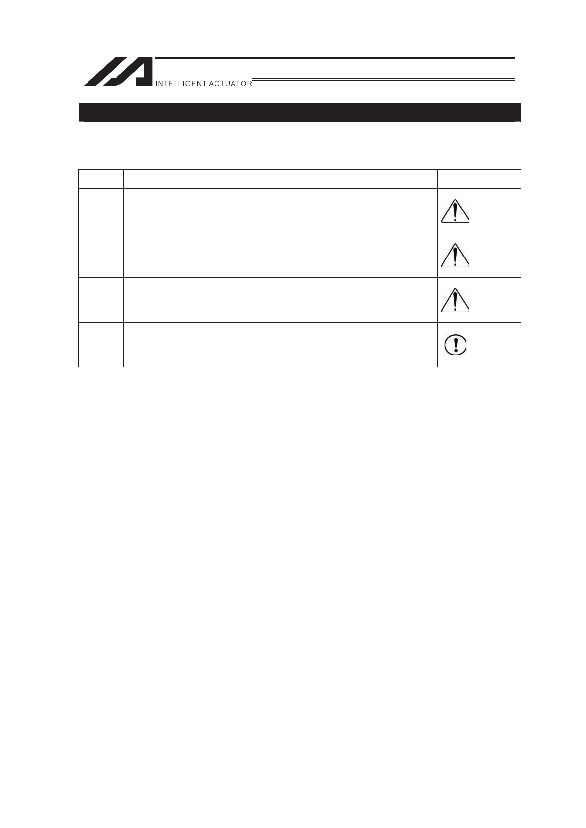
The safety precautions are divided into “Danger”, “Warning”, “Caution” and “Notice” according to
the warning level, as follows, and described in the operating manual for each model.
Level Degree of Danger and Damage Symbol
Danger
This indicates an imminently hazardous situation which, if the product
is not handled correctly, will result in death or serious injury.
Danger
Warning
This indicates a potentially hazardous situation which, if the product is
not handled correctly, could result in death or serious injury.
Warning
Caution
This indicates a potentially hazardous situation which, if the product is
not handled correctly, may result in minor injury or property damage.
Caution
Notice
This indicates lower possibility for the injury, but should be kept to use
this product properly.
Notice
Page 14
8
Caution in Handling
1. Make sure to follow the usage condition, environment and specification
range of the product.
Operaton out of the guarantee could cause a drop in performance or malfunction of the
product.
2. Back and forth operation in a short distance may cause wear of grease.
If the actuators are moved back and forth continuously over a short distance of 30 mm or
less, grease film may run out. As a guide, move the actuators back and forth repeatedly for
around 5 cycles over a distance of 50 mm or more after every 5,000 to 10,000 cycles. Keep
using the actuators with the grease worn out may cause malfunction.
3. Make sure to attach the actuator properly by following this operating
manual.
Using the product with the actuator not being certainly retained or affixed may cause
abnormal noise, vibration, malfunction or shorten the product life.
Warning: Do not get closer than 30cm if you are a person who needs a support of a
medical device such as a pacemaker. This actuator uses high-performance
rare-earth permanent magnets. Therefore an unexpected operation may be
caused to a medical device especially when using such a device such as a
pacemaker.
Caution:
• Do not attempt to get a magnetic card close to the product. Having a magnetic
storage medium close to the product may disable the medium by destroying data.
• Do not attempt to get a precision instrument such as an electric watch close to the
product. Doing so may cause a trouble to the instrument
Page 15

9
International Standards Compliances
This actuator complies with the following overseas standard.
Refer to Overseas Standard Compliance Manual (ME0287) for more detailed information.
RoHS Directive CE Marking
Page 16
10
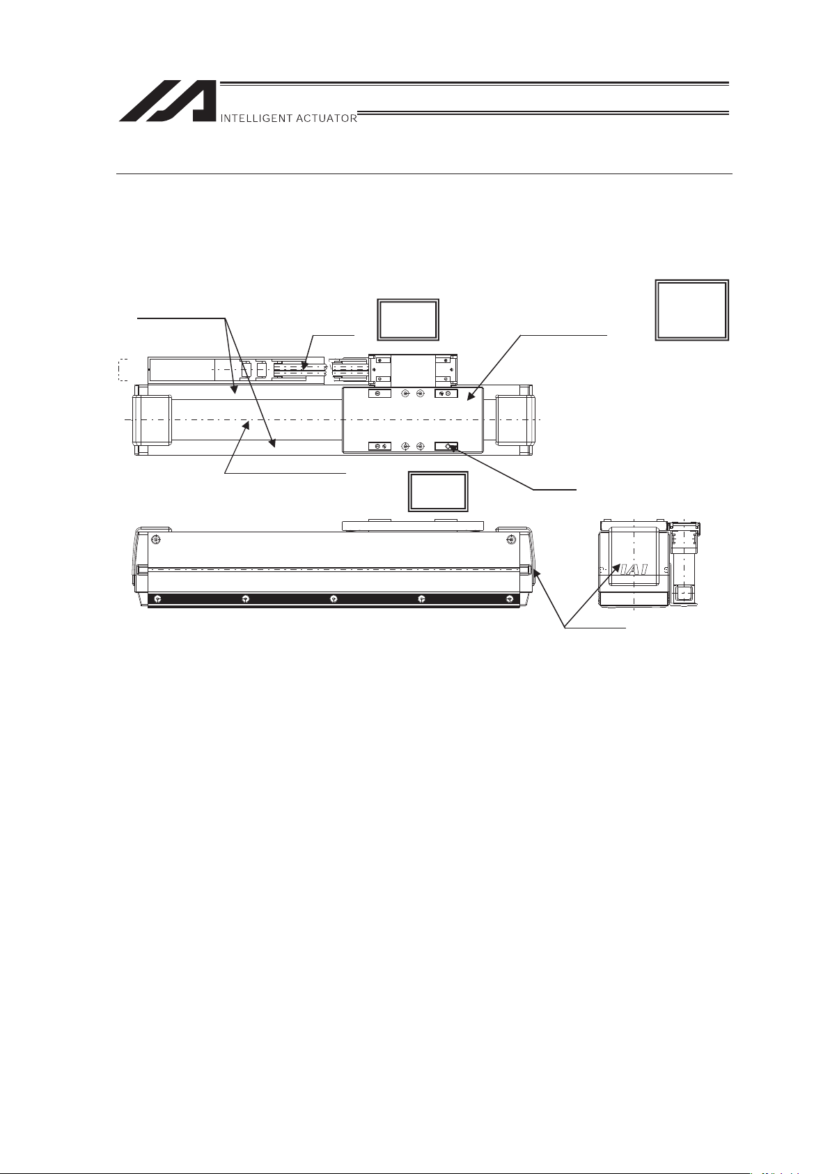
Names of the Parts
This manual defines the right and left of the actuator by putting it horizontally as shown in the
figures below and viewing it from the top and home side. Also the front side means the opposite of
the home side.
Side covers
Cable
Right
Slider cover
Stainless sheet
Left
Slider
Home
side
Cover
Drawings for Standard Type
(Reference) In the above figure, the cables are facing top, while the home is located on the right
side.
The actuator is shipped with its home adjusted to the side specified by the customer.
Accordingly, the home position on your actuator may be different from the direction
shown in the figure.
Page 17
11
1. Specifications Check
1.1 Checking the Product
The standard configuration of this product is comprised of the following parts.
See the component list for the details of the enclosed components. If you find any faulty or missing
parts, contact your local IAI distributor.
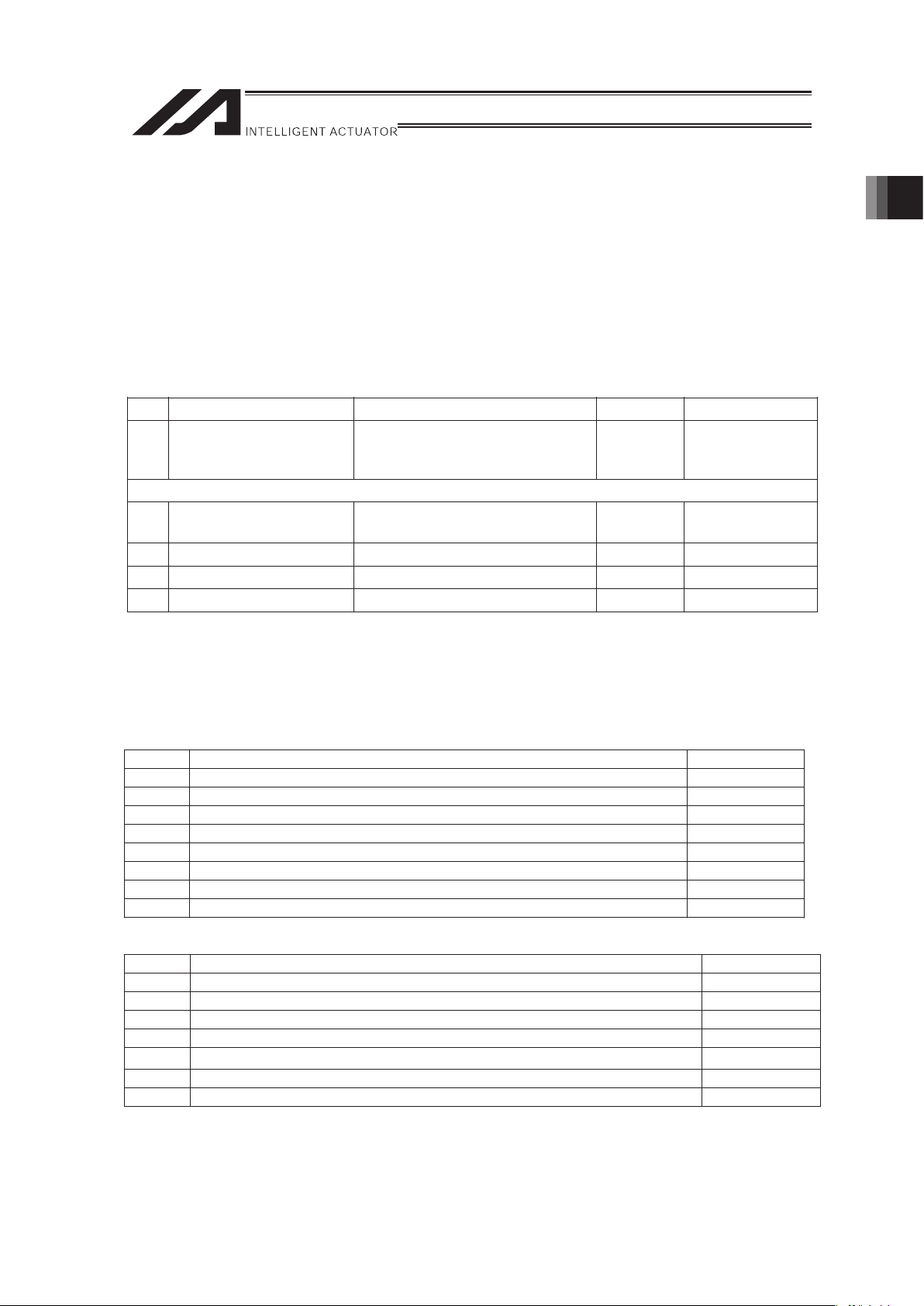
1.1.1 Parts
No. Name Model number Quantity Remarks
1 Actuator
Refer to “How to Read the Model
Nameplate” and “How to Read
the Model Number.”
1
Accessories
2
Motor • encoder cables
(Note1)
1 set
3 First Step Guide 1
4 Operating Manual (DVD) 1
5 Safety Guide 1
Note1 The motor • encoder cables differ between the standard model and robot cable.
[Refer to 1.5 “Motor • Encoder Cables.”]
1.1.2 Operating Manuals for the Controllers Related to this Product
(1) Manuals Related to XSEL-P/Q Controllers
No. Name Control
No.
1 Operating Manual for XSEL-P/Q/PCT/QCT Controller ME0148
2 Operating Manual for XSEL-P/Q/PX/QX RC Gateway Function ME0188
3 Operating Manual for PC Software IA-101-X-MW/IA-101-X-USBMW ME0154
4 Operating Manual for Teaching Pendant SEL-T/TD/TG ME0183
5 Operating Manual for Teaching Pendant IA-T-X/XD ME0160
6 Operating Manual for DeviceNet ME0124
7 Operating Manual for CC-Link ME0123
8 Operating Manual for PROFIBUS ME0153
(2) Manuals Related to SSEL Controllers
No. Name Control
No.
1 Operating Manual for SSEL Controller ME0157
2 Operating Manual for PC Software IA-101-X-MW/IA-101-X-USBMW ME0154
3 Operating Manual for Teaching Pendant SEL-T/TD/TG ME0183
4 Operating Manual for Teaching Pendant IA-T-X/XD ME0160
5 Operating Manual for DeviceNet ME0124
6 Operating Manual for CC-Link ME0123
7 Operating Manual for PROFIBUS-DP ME0153
1. Specications Check
Page 18
12
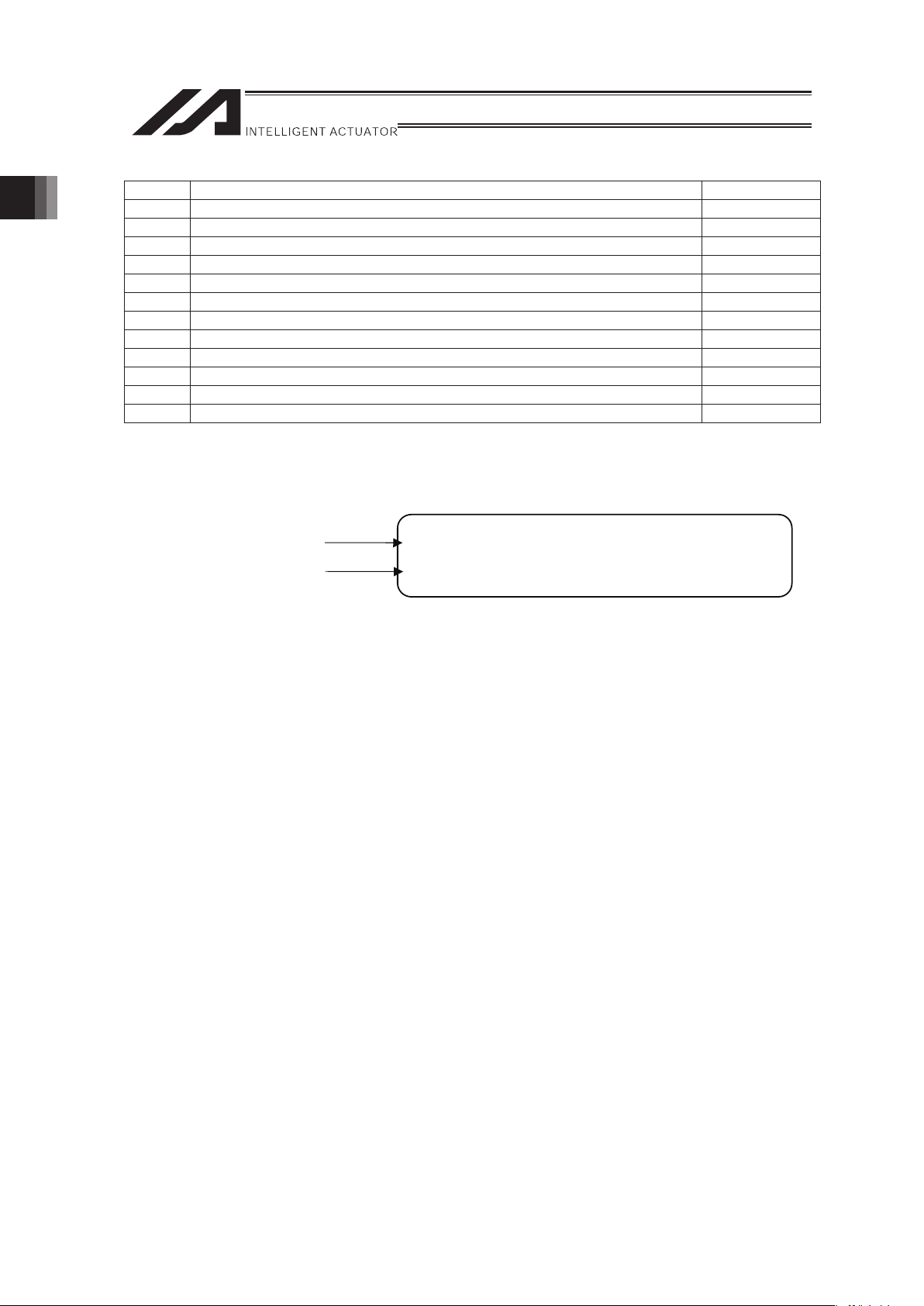
(3) Manuals Related to SCON Controllers
No. Name Control
No.
1 Operating Manual for SCON Controller ME0161
2 Operating Manual for SCON-CA Controller SCON-CA ME0243
3 Operating Manual for PC Software RCM-101-MW/RCM-101-USB ME0155
4 Operating Manual for Teaching Pendant CON-T/TG ME0178
5 Operating Manual for Touch Panel Teaching CON-PT/PD/PG ME0227
6 Operating Manual for Touch Panel Teaching CON-PTA/PDA/PGA ME0295
7 Operating Manual for Simplified Teaching Pendant RCM-E ME0174
8 Operating Manual for Data setter RCM-P ME0175
9 Operating Manual for Touch Panel Display RCM-PM-01 ME0182
10 Operating Manual for DeviceNet ME0124
11 Operating Manual for CC-Link ME0123
12 Operating Manual for PROFIBUS-DP ME0153
1.1.3 How to Read the Model Nameplate
Model
Serial Numbe
r
MODEL LSA-S6SS-I-100-48-T2-P-CT2
SERIAL No.600117640 MADE IN JAPAN
1. Specications Check
Page 19
13
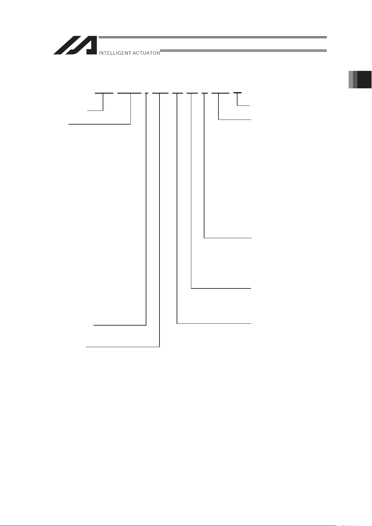
1.1.4 How to Read the Model Number
L S A - S 6 S S - I - 1 0 0 - 4 8 - T 2 - P - C T 2 - * *
Note 1 It may be displayed for IAI use. It is not a code to show the model type.
Series Name
<Type>
Shaft Type
S6SS:
width 60mm Single Slider
S6SM:
width 60mm Double Slider
S8SS:
width 80mm Single Slider
S8SM:
width 80mm Double Slider
S8HS:
width 80mm High-Thrust
Single Slider
S8HM:
width 80mm High-Thrust
Double Slider
S10SS:
width 100mm Single Slider
S10SM:
width 100mm Double Slider
S10HS:
width 100mm High-Thrust
Single Slider
S10HM:
width 100mm High-Thrust
Double Slider
<Encoder Type>
I: Incremental
<Motor Type>
100: 100W
200: 200W
200S: 200W
Identification for IAI use only
(Note1)
<Options>
None:
Cable Track
Attachment Orientation
(Standard Equipment)
CT2 to 6
Cable Track
Attachment Orientations 2 to 6
US1 to 6
Cable Track for User S type
Attachment Orientations 1 to 6
UM1 to 6
Cable Track for User M type
Attachment Orientations 1 to 6
<Cable length>
N : None
P : 1m
S : 3m
M : 5m
X��
:
Length Specification
<Controller>
T2 : SCON
: SSEL
: XSEL-P/Q
<Stroke>
[Refer to 1.2 “Specifications”]
1. Specications Check
Page 20
14
1.2 Specification
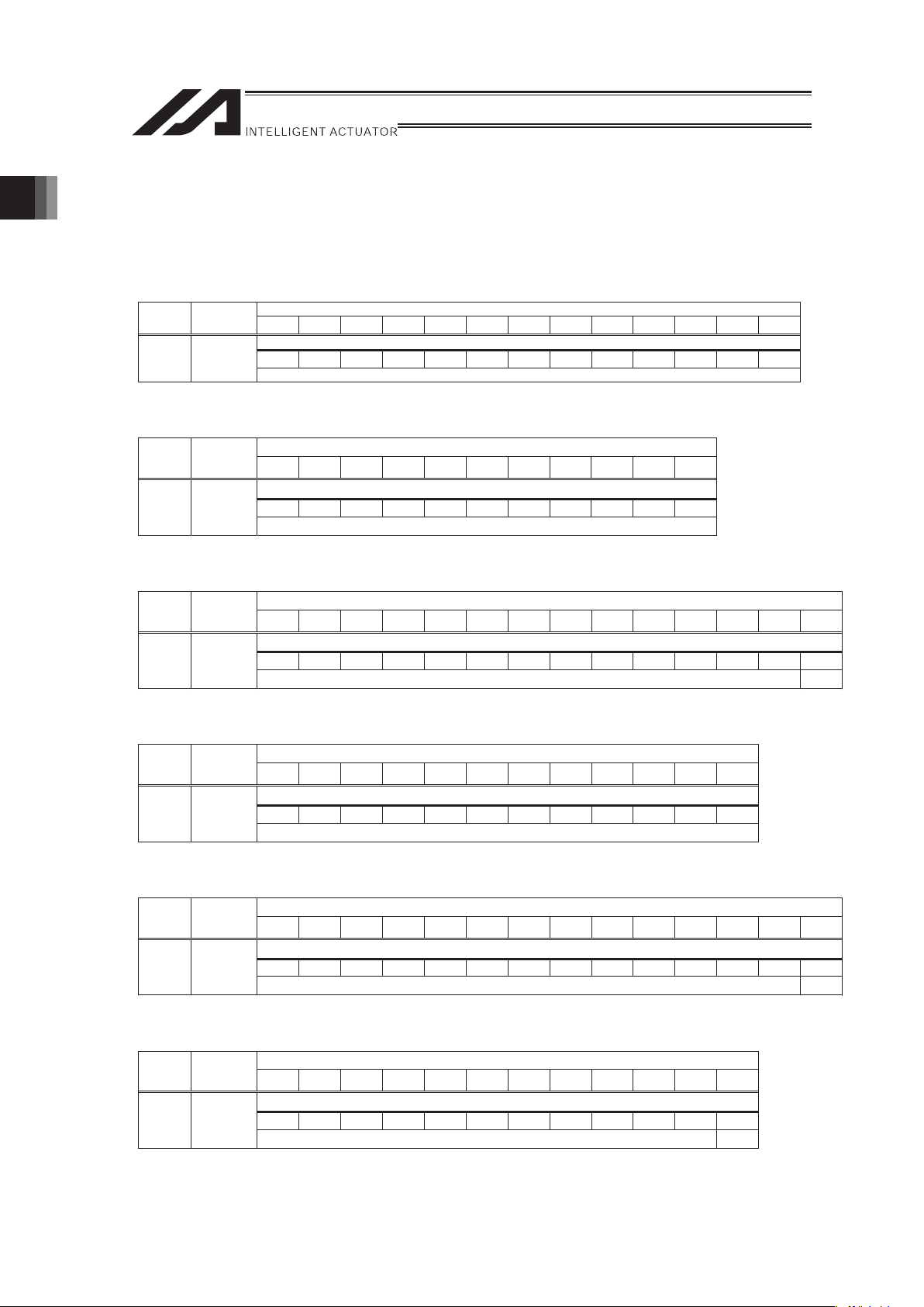
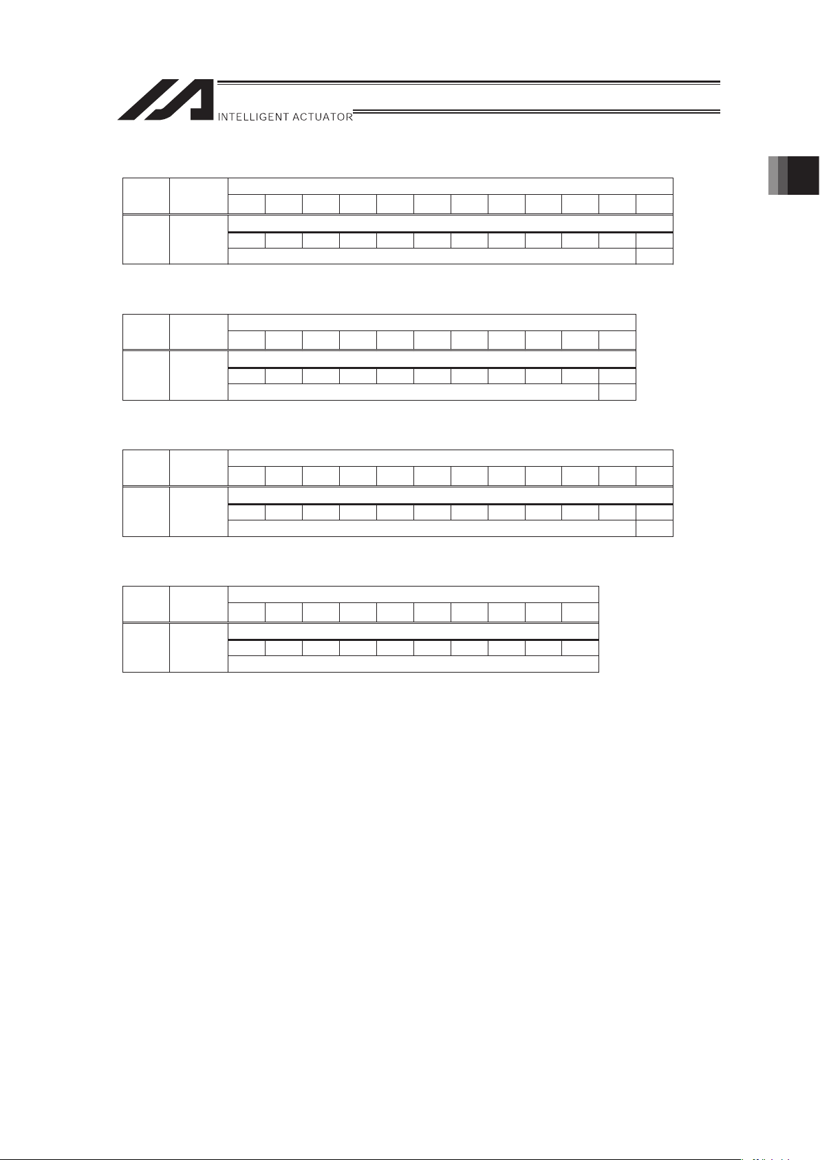
1.2.1 Speed
[1] S6SS
Speed limits (Unit: mm/s)
Stroke [mm]
Motor
Type
Minimum
Speed
48 96 144 192 240 288 336 384 432 480 528 576 624
2500
672 720 768 816 864 912 960 1008 1056 1104 1152 1200 1248
100 �
2500
[2] S6SM
Speed limits (Unit: mm/s)
Stroke [mm]
Motor
Type
Minimum
Speed
40 88 136 184 232 280 328 376 424 472 520
2500
568 616 664 712 760 808 856 904 952 1000 1048
100 �
2500
[3] S8SS
Speed limits (Unit: mm/s)
Stroke [mm]
Motor
Type
Minimum
Speed
60 120 180 240 300 360 420 480 540 600 660 720 780 840
2500
900 960 1020 1080 1140 1200 1260 1320 1380 1440 1500 1560 1620 -
100 �
2500 -
[4] S8SM
Speed limits (Unit: mm/s)
Stroke [mm]
Motor
Type
Minimum
Speed
60 120 180 240 300 360 420 480 540 600 660 720
2500
780 840 900 960 1020 1080 1140 1200 1260 1320 1380 1440
100W �
2500
[5] S8HS
Speed limits (Unit: mm/s)
Stroke [mm]
Motor
Type
Minimum
Speed
60 120 180 240 300 360 420 480 540 600 660 720 780 840
2500
900 960 1020 1080 1140 1200 1260 1320 1380 1440 1500 1560 1620 -
100 �
2500 -
[6] S8HM
Speed limits (Unit: mm/s)
Stroke [mm]
Motor
Type
Minimum
Speed
60 120 180 240 300 360 420 480 540 600 660 720
2500
780 840 900 960 1020 1080 1140 1200 1260 1320 1380 -
100 �
2500 -
1. Specications Check
Page 21
15
[7] S10SS
Speed limits (Unit: mm/s)
Stroke [mm]
Motor
Type
Minimum
Speed
90 180 270 360 450 540 630 720 810 900 990 1080
2500
1170 1260 1350 1440 1530 1620 1710 1800 1890 1980 2070 -
200 �
2500 -
[8] S10SM
Speed limits (Unit: mm/s)
Stroke [mm]
Motor
Type
Minimum
Speed
60 150 240 330 420 510 600 690 780 870 960
2500
1050 1140 1230 1320 1410 1500 1590 1680 1770 1860 -
200 �
2500 -
[9] S10HS
Speed limits (Unit: mm/s)
Stroke [mm]
Motor
Type
Minimum
Speed
90 180 270 360 450 540 630 720 810 900 990 1080
2500
1170 1260 1350 1440 1530 1620 1710 1800 1890 1980 2070 -
200S �
2500 -
[10] S10HM
Speed limits (Unit: mm/s)
Stroke [mm]
Motor
Type
Minimum
Speed
105 195 285 375 465 555 645 735 825 915
2500
1005 1095 1185 1275 1365 1455 1545 1635 1725 1815
200S �
2500
1. Specications Check
Page 22
16
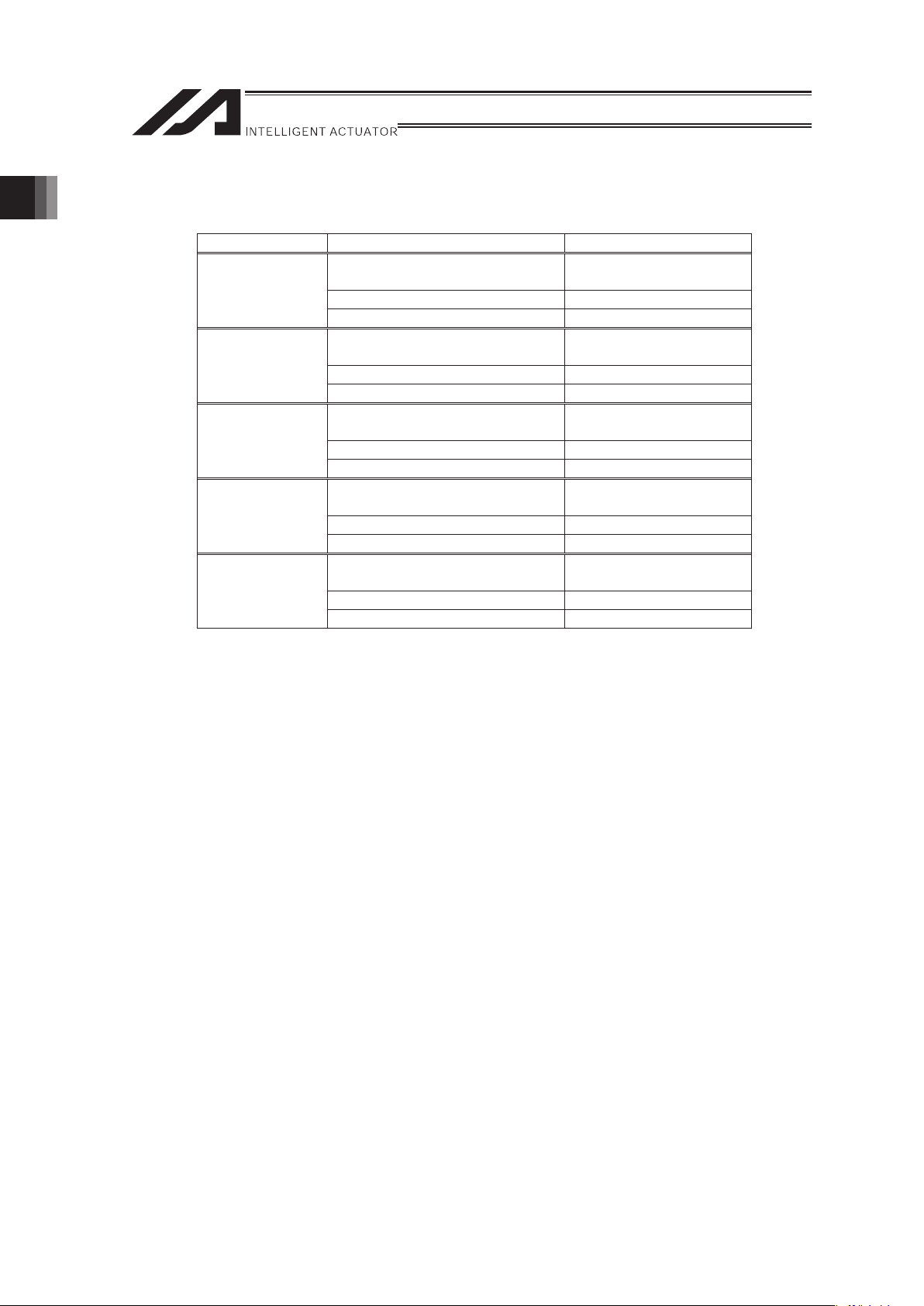
1.2.2 Maximum acceleration/deceleration, Maximum load capacity and Rated thrust
Type Item Specifications
Maximum
acceleration/deceleration
(Note 1)
3G
Maximum load capacity
(Note 1)
3kg
S6SS, S6SM
Rated thrust 15N
Maximum
acceleration/deceleration
(Note 1)
3G
Maximum load capacity
(Note 1)
5kg
S8SS, S8SM
Rated thrust 25N
Maximum
acceleration/deceleration
(Note 1)
3G
Maximum load capacity
(Note 1)
7kg
S8HS, S8HM
Rated thrust 35N
Maximum
acceleration/deceleration
(Note 1)
3G
Maximum load capacity
(Note 1)
15kg
S10SS, S10SM
Rated thrust 65N
Maximum
acceleration/deceleration
(Note 1)
3G
Maximum load capacity
(Note 1)
20kg
S10HS, S10HM
Rated thrust 80N
Note 1 The available acceleration/deceleration and the transportable weight may differ
depending on the operational conditions.
[Refer to 1.3 “Operating conditions”]
1. Specications Check
Page 23
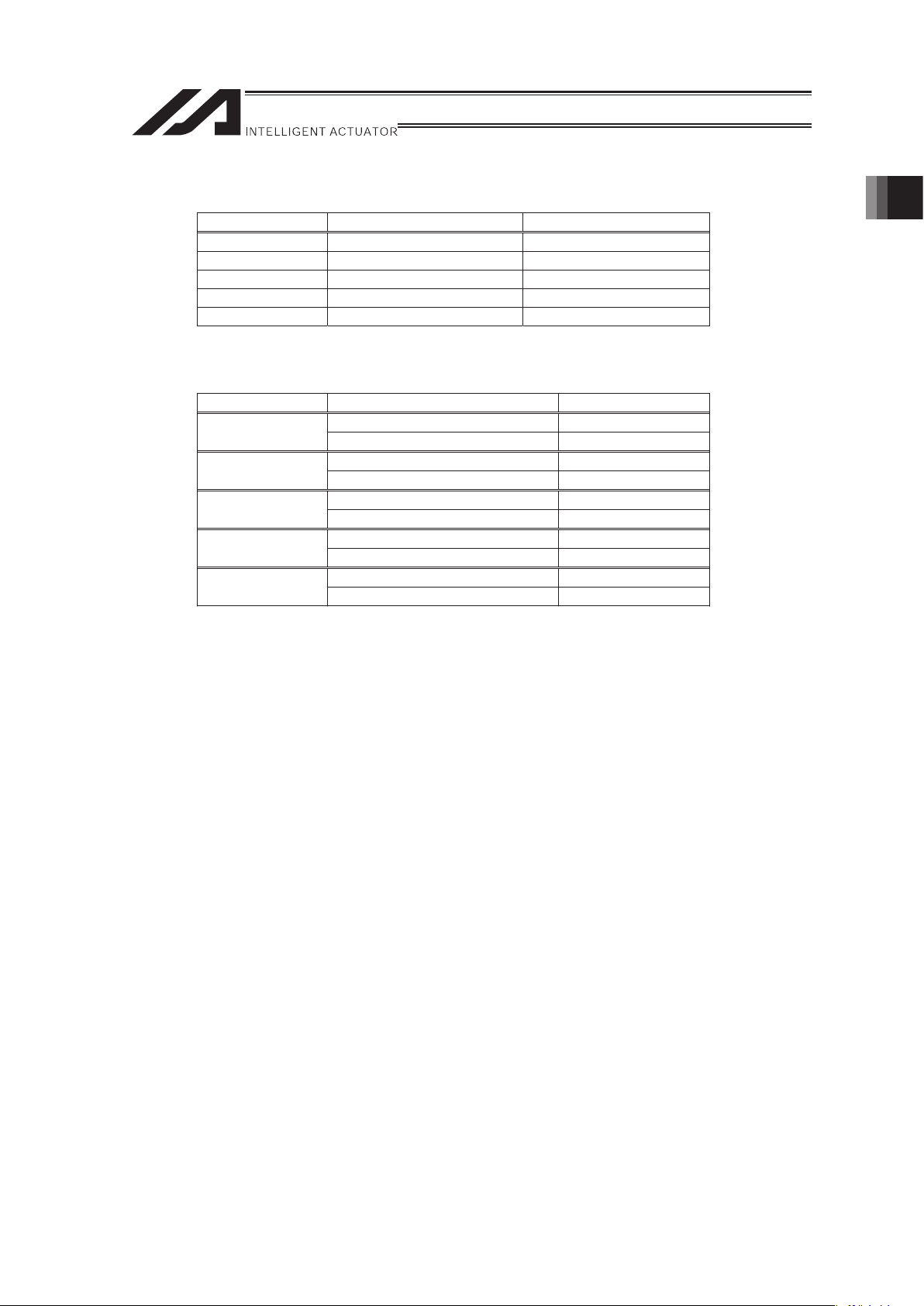
17
1.2.3 No. of Encoder Pulses
Type No. of Encoder Pulses Lead Length [mm]
S6SS, S6SM 48000 48
S8SS, S8SM 60000 60
S8HS, S8HM 60000 60
S10SS, S10SM 90000 90
S10HS, S10HM 90000 90
1.2.4 Positioning Precision
Type Item Specifications
Positioning Repeatability ±0.005mm
S6SS, S6SM
Lost Motion 0.02mm or le
ss
Positioning Repeatability ±0.005mm
S8SS, S8SM
Lost Motion 0.02mm or le
ss
Positioning Repeatability ±0.005mm
S8HS, S8HM
Lost Motion 0.02mm or le
ss
Positioning Repeatability ±0.005mm
S10SS, S10SM
Lost Motion 0.02mm
or
le
ss
Positioning Repeatability ±0.005mm
S10HS, S10HM
Lost Motion 0.02mm or le
ss
The values shown above are the accuracy at the delivery from the factory.
It does not include the consideration of time-dependent change as it is used.
1. Specications Check
Page 24
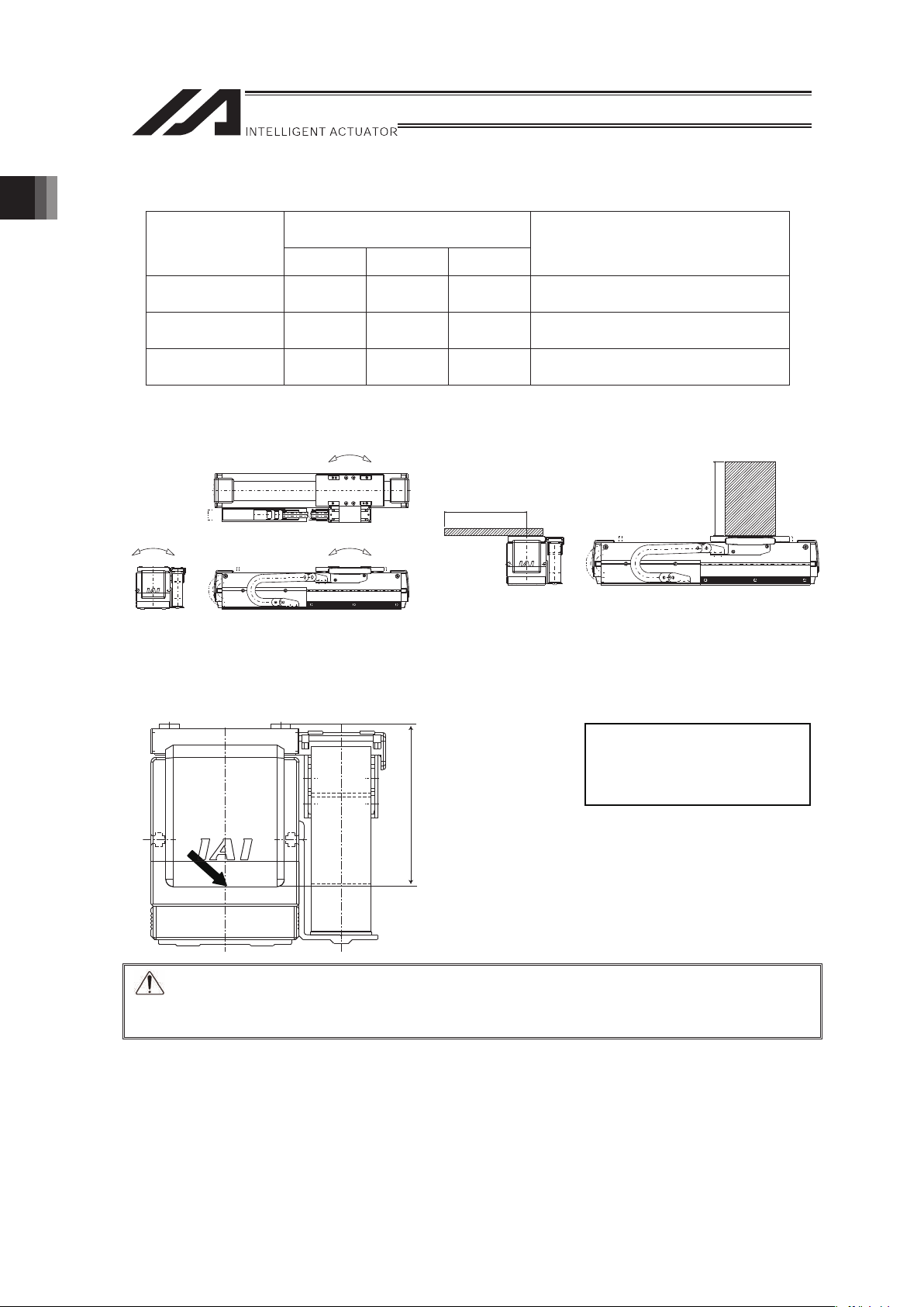
18
1.2.5 Allowable Load Moments of the Actuator
Allowable Dynamic Load Moment
[N·m]
Type
Ma Mb Mc
Allowable Overhang
Load Length (L)
(Note 1)
S6SS, S6SM 28.9 41.2 22.5
Ma direction: 300mm or less
Mb, Mc direction: 300mm or less
S8SS, S8SM
S8HS, S8HM
42.2 60.3 37.6
Ma direction: 300mm or less
Mb, Mc direction: 300mm or less
S10SS, S10SM
S10HS, S10HM
57.4 81.9 60.8
Ma direction: 300mm or less
Mb, Mc direction: 300mm or less
Note 1: The values for allowable overhang load length are those when the center of the gravity of
the load is at 1/2 of the overhang length.
Conduct moment calculations for Ma and Mc with the point indicated with an allow below as the
datum.
Caution: Using the product above the allowable moment or overhang load length may cause
not only to generate abnormal noise or vibration, but also to shorten the product life
remarkably.
1.2.6 Duty Ratio in Continuous Operation
The duty ratio may differ depending on the acceleration/deceleration and transported weight.
[Refer to 1.3 “Operating conditions”]
Dimension A
S6SS, SM : 69mm
S8SS, SM, HS, HM : 79mm
S10SS, SM, HS, HM : 99mm
Slider top surface
Guide
A
Mb
MaMc
Drawings for Standard Type
Mb or Mc direction
L
Ma direction
L
Drawings for Standard Type
1. Specications Check
Page 25
19
1.3 Operating conditions
1.3.1 Available Conditions for Operation
When selecting a desired model of shaft-type linear servo actuator, you must ensure that the
selected actuator satisfies the following two conditions.
[Condition 1]
The thrust required for acceleration
must not exceed the maximum thrust of the shaft-type linear
servo actuator.
[Condition 2]
The thrust during continuous operation
must not exceed the rated thrust of the shaft-type linear
servo actuator.
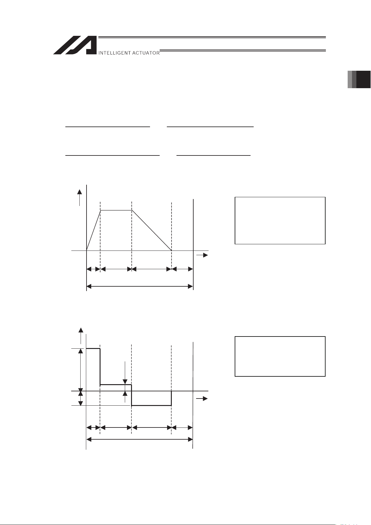
The above conditions are explained by using a trapezoid operation as an example.
Speed
Time
ta tf td
t
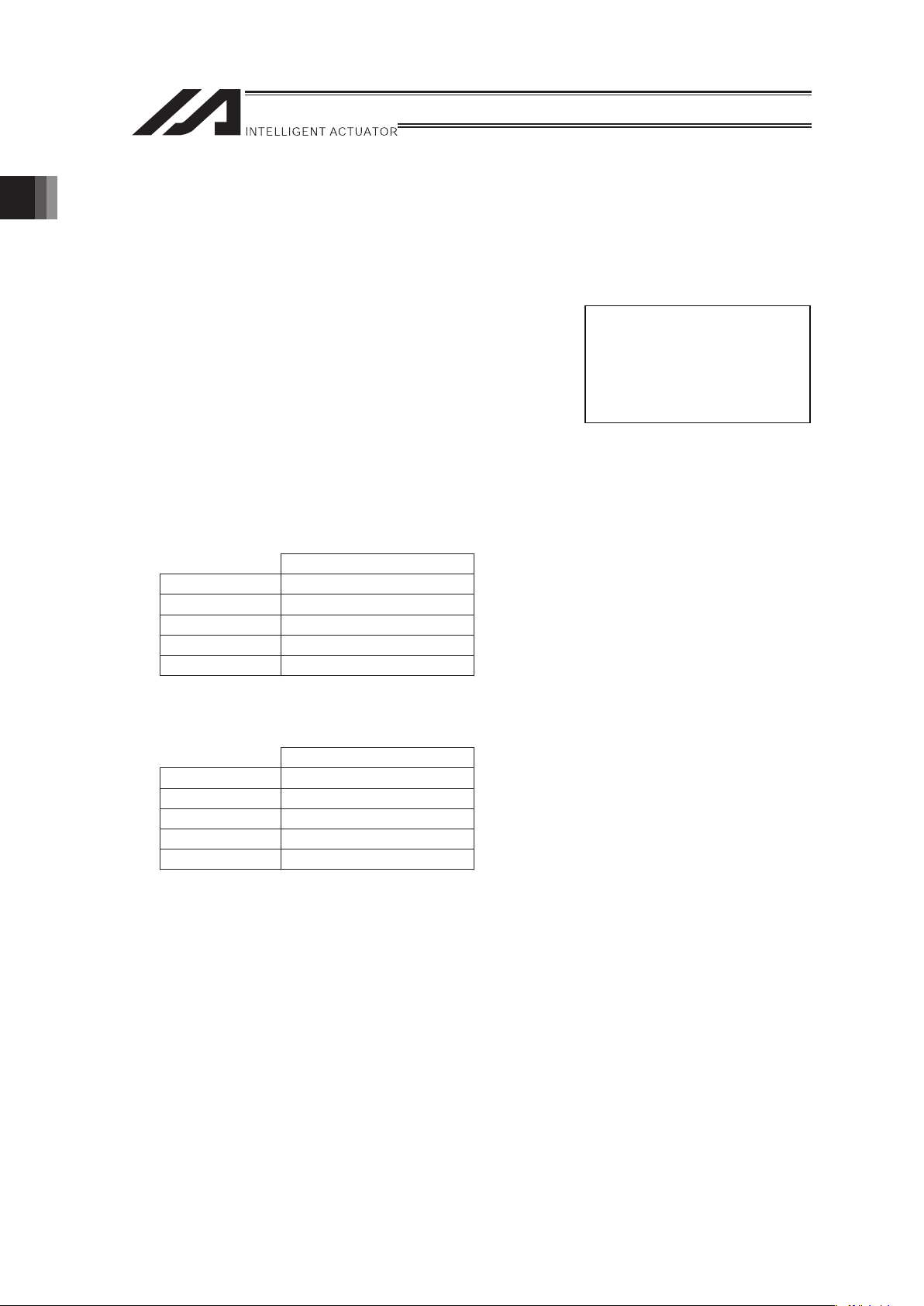
The above operation pattern can be expressed differently in a graph where the vertical axis
represents thrust.
Thrust
Time
ta tf td
t
Fa
Fd
Ff
t : Operation time per cycle
(sec)
ta : Acceleration time (sec)
tf : Moving time at constant
speed (sec)
td : Deceleration time (sec)
Fa : Thrust required for
acceleration (N)
Ff : Traveling resistance (N)
Fd : Thrust required for
deceleration (N)
1. Specications Check
Page 26
20
1.3.2 Availability Judgment for each Operational Condition
[1] Condition 1 Judgment of Thrust Necessary for Acceleration
For the slider to accelerate according to a command, the thrust required for acceleration, or Fa,
must be smaller than the maximum thrust of the shaft-type linear servo actuator.
Fa = (M + m) • a + Ft
Here,
M : Slider weight (kg)
m : Slider payload (kg)
a : Commanded acceleration (m/s
2
)* *1G = 9.8m/s2
Ff : Traveling resistance (N)
In the case of a shaft-type linear servo actuator, the traveling resistance is determined by the
speed and empirically calculated as specified below.
[Traveling resistance]
The table below lists the traveling resistance of each model.
T
ravelin
g resistance Ff (N)
S6SS, S6SM 5V + 5
S8SS, S8SM 9V + 7
S8HS, S8HM 9V + 7
S10SS, S10SM 20V + 13.5
S10HS, S10HM 20V + 13.5
If the obtained Fa is smaller than the maximum thrust of the shaft-type linear servo actuator,
condition 1 is satisfied.
Maximum
thrust (N)
S6SS, S6SM 60
S8SS, S8SM 100
S8HS, S8HM 140
S10SS, S10SM 260
S10HS, S10HM 320
[Slider weight]
S6SS, S6SM : 1.4kg
S8SS, S8SM : 1.7kg
S8HS, S8HM : 2.0kg
S10SS, S10SM : 3.5kg
S10HS, S10HM : 4.0kg
V: Slider speed (m/s)
(Achieved speed is used in
a triangle wave operation.)
1. Specications Check
Page 27
21
[2] Condition 2 Judgment of Thrust for Continuous Operation
It is necessary that the continuous operational thrust Ft considering the load and duty is
smaller than the rated thrust.
Fa : Thrust required for acceleration (N)
ta : Acceleration time (sec)
td : Deceleration time (sec)
Ff : Traveling resistance (N)
tf : Moving time at constant speed (sec)
t : Operation time per cycle (sec) (t = ta + tf + td + 0.15)
Here, Fd indicates the thrust required for deceleration and can be calculated as follows:
Fd = (M +m) • d – Ff
M : Slider weight (kg)
m : Slider payload (kg)
d : Commanded deceleration (m/s
2
)
Ff : Traveling resistance (N)
Condition 2 is satisfied if the continuous operational thrust Ft figured out as described above is
smaller than the rated thrust.
Rated
thrust (N)
S6SS, S6SM 15
S8SS, S8SM 25
S8HS, S8HM 35
S10SS, S10SM 65
S10HS, S10HM 80
The actuator can be used in any operating conditions that satisfy both conditions 1 and 2
specified above.
If either condition cannot be satisfied, take appropriate measures such as reducing the slider
load, acceleration or duty.
[Stabilization time tc]
S6SS, S6SM : 0.15 sec
S8SS, S8SM : 0.2 sec
S8HS, S8HM : 0.2 sec
S10SS, S10SM : 0.2 sec
S10HS, S10HM : 0.2 sec
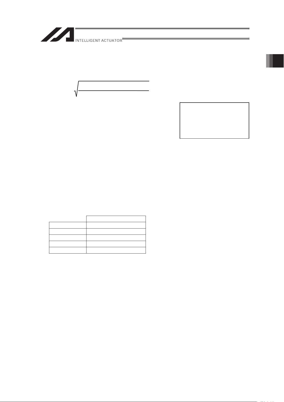
F
a
2
ta+ F
f
2
tf+ F
d
2
t
d
t
F
t
1. Specications Check
Page 28

22
1.3.3 Example for Judging Operation Availability by Operational Conditions
[Operating conditions]
• Applicable model : S8SS/S8SM type
• Speed : 2.0m/s
• Acceleration : 24.5m/s
2
(The deceleration is
assumed to be the same.)
• Travel : 1.5m
• Slider payload : 2kg
• The actuator moves back and forth over a stroke of 1.5m.
The above operation pattern can be illustrated by
the graph shown to the right.
Now, let’s start calculation according to “Selection Method.”
1) Figure out the maximum thrust of Condition 1.
Apply the above operation pattern to the aforementioned equation of maximum thrust.
Fa = (M +m) • a + Ff
Here,
M : Slider weight (1.7kg for the S8SS/S8SM)
m : Slider load (kg) : 2kg in this example
a : Commanded acceleration (m/s
2
) : 24.5m/s2 in this example
Ff : Traveling resistance (N) : 25N in this example
From above, Fa is calculated as follows:
Fa
= (3.7
× 24.5 + 25) � 115.65N
The calculated value exceeds the maximum thrust 100N of the S8SS/S8SM.
Let’s lower the specified acceleration to 19.6m/s
2
. Fa changes as follows:
Fa = (3.7 × 19.6 + 25) � 97.52N.
The calculated value is smaller than the maximum thrust 100N of the S8SS/S8SM.
1G = 9.8m/s2
Speed
Time
ta tf td
t
1. Specications Check
Page 29

23
2) Figure out the continuous operational thrust of Condition 2.
Substitute the operation pattern of the previous page to the continuous operational thrust
formula.
Based on the examination result of maximum thrust, the specified acceleration is assumed as
19.6m/s
2
.
Here,
Fa = 97.52N, Ff = 25N, Fd = 47.52N, ta = td = 0.10sec, tf = 0.65sec, t = 0.85sec
From the above, Ft is calculated as 43.16N.
Since this value exceeds the rated thrust 25N of the S8SS/S8SM, this actuator cannot be
used in the aforementioned operation pattern.
Let’s lower the duty and see what happens.
Repeat the above calculation based on t = 2.6sec.
Speed
Time
t = 2.6
ta tf td
This time, Ft is calculated as 24.68N.
Accordingly, the actuator can be used in this operation pattern.
F
a
2
ta+ F
f
2
tf+ F
d
2
t
d
t
F
t
1. Specications Check
Page 30

24
1.4 Option
1.4.1 Cable Track Attachment Orientations 2 to 6 (Model: CT2 to CT6)
These are the attachment orientation indications with no cable track for user (option).
The attachment orientation of cable track is either the four orientations in Standard Horizontal
Orientation Mount or two orientations in Horizontally Oriented Wall Mount.
Refer to the table below for the availability of Single Slider and Double Slider.
Option Model Attachment Orientation Single Slider Double Slider
None Attachment Orientation 1
� �
CT2 Attachment Orientation 2
�
�
CT3 Attachment Orientation 3
�
�
CT4 Attachment Orientation 4
�
�
CT5 Attachment Orientation 5
� �
CT6 Attachment Orientation 6
�
�
[Attachment Orientation]
Attachment Orientation 1
(Standard)
Attachment Orientation 2
(Opposite Type) CT2
Attachment Orientation 3
CT3
Single Slider is to be attached
in the orientation shown in the
figure below. Multi Slider is to
be attached in the orientation
shown in the figure below on
both right and left sides.
It is the opposite type in the
attachment to Attachment
Orientation 1 (Standard).
It is the type with the home
position on the opposite side
from Attachment Orientation 1
(Standard).
Attachment Orientation 4
CT4
Attachment Orientation 5
(Standard Horizontally
Oriented Wall Mount) CT5
Attachment Orientation 6
(Opposite Type Horizontally
Oriented Wall Mount) CT6
It is the opposite type in the
attachment to and also the
home position on the
opposite side from
Attachment Orientation 1
(Standard).
Single Slider is to be attached
in the orientation shown in the
figure below. Multi Slider is to
be attached in the orientation
shown in the figure below on
both right and left sides.
It is the opposite type in the
attachment to Attachment
Orientation 6 (Standard
Horizontally Oriented Wall
Mount).
1. Specications Check
Page 31

25
1.4.2 Cable Track for User S Type Attachment Orientations 1 to 6 (Model: US1 to US6)
These are the indications when attaching S Type User Cable Track to the standard cable track.
Attachment orientation is also to be indicated. The attachment orientation of cable track is either
the four orientations in Standard Horizontal Orientation Mount or two orientations in Horizontally
Oriented Wall Mount. [Refer to “[Attachment Orientation]” in the “1.4.1 Cable Track Attachment
Orientations 2 to 6 (Model: CT2 to CT6)”]
Refer to the table below for the availability of Single Slider and Double Slider.
Option Model Attachment Orientation Single Slider Double Slider
US1 Attachment Orientation 1
� �
US2 Attachment Orientation 2
�
�
US3 Attachment Orientation 3
�
�
US4 Attachment Orientation 4
�
�
US5 Attachment Orientation 5
� �
US6 Attachment Orientation 6
�
�
[Dimensional Drawing for S Type User Cable]
65
14
91
15
Horizontal Type Horizontally Oriented
Wall Mount Type
Cable Track for user
14
15
60
1. Specications Check
Page 32

26
1.4.3 Cable Track for User M Type Attachment Orientations 1 to 6 (Model: UM1 to UM6)
These are the indications when attaching M Type User Cable Track to the standard cable track.
Attachment orientation is also to be indicated. The attachment orientation of cable track is either
the four orientations in Standard Horizontal Orientation Mount or two orientations in Horizontally
Oriented Wall Mount. [Refer to “[Attachment Orientation]” in the “1.4.1 Cable Track Attachment
Orientations 2 to 6 (Model: CT2 to CT6)”]
Refer to the table below for the availability of Single Slider and Double Slider.
Option Model Attachment Orientation Single Slider Double Slider
UM1 Attachment Orientation 1
� �
UM2 Attachment Orientation 2
�
�
UM3 Attachment Orientation 3
�
�
UM4 Attachment Orientation 4
�
�
UM5 Attachment Orientation 5
� �
UM6 Attachment Orientation 6
�
�
[Dimensional Drawing for M Type User Cable]
14
88
40
91
14
40
85
Cable Track for user
Horizontal Type Horizontally Oriented
Wall Mount Type
1. Specications Check
Page 33

27
1.5 Motor • Encoder Cables
1.5.1 Motor • Encoder Cables for Linear Servo Actuator
[1] Motor Cable (Model : CB-X-MA���)
��� indicates the cable length (L) (Example: 080=8m), Max.30m
4
1
1
4
Green
Red
White
Black
PE
U
V
W
1
2
3
4
Red
White
Black
Green
U
V
W
PE
1
2
3
4
(18)
(41)
(16)
(φ9)
L
(20) (10)
(21)
Controller Side Mechanical Side
(Front View)
[Bending Radius]
When used under moving condition : 51mm
When used in fixed condition : 34mm
(Front View)
Electric
Wire Color
Signal
Abbreviation
Pin
No.
Width
Electric
Wire Color
Signal
Abbreviation
Pin
No.
Width
AWG 19
(0.75mm
2
)
(Solderless)
AWG 19
(0.75mm
2
)
1. Specications Check
Page 34

28
[2] Encoder Cable (Model : CB-X3-PA���)
��� indicates the cable length (L) (Example: 080=8m), Max.30m
(41)
Controller Side
(37)
Mechanical Side
(Front View)
(25)
1
9
L
Ground wire and
braided shield wires
AWG26
(0.12mm
2
)
(Solderless)
AWG26
(0.12mm
2
)
(Soldered)
-
-
-
White/Green
White/Orange
-
-
-
-
-
-
White/Blue
White/Yellow
White/Red
White/Black
White/Purple
White/Gray
Orange
Green
Purple
Gray
Red
Brack
Blue
Yellow
-
-
-
E24V
0V
LS
CREEP
OT
RSV
-
-
-
A+
A-
B+
B-
Z+
Z-
SRD+
SRD-
BAT
+
BAT
VCC
GND
BKR-
BKR+
-
10
11
12
13
26
25
24
23
9
18
19
1
2
3
4
5
6
7
8
14
15
16
17
20
21
22
White/Blue
White/Yellow
White/Red
White/Black
White/Purple
White/Gray
White/Orange
-
Ground
Orange
Green
Purple
Gray
Red
Black
White/Green
Blue
Yellow
A
A
B
B
Z
Z
LS+
FG
SD
BAT
+
BAT
-
LS-
1
2
3
4
5
6
7
8
9
10
11
12
13
14
15
16
17
18
The shield is clamped to the hood
[Bending Radius]
When used under moving condition : 58mm
When used in fixed condition : 38mm
Electric
Wire Color
Signal
Abbreviation
Pin
No.
Width
Electric
Wire Color
Signal
Abbreviation
Pin
No.
Width
(13)
14
26
1
13
(φ10)
(14)
(15)
(Front View)
SD
VCC
GND
BK-
BK+
1. Specications Check
Page 35

29
1.5.2 Cable in the bearer
[1] Motor cable
Width
AWG 20
(0.5mm
2
)
Red U 1
White V 2
Black W 3
Green PE 4
1 U Red
2 V White
3 W Black
4 PE Green
AWG 20
(0.5mm
2
)
Electric
Wire Color
Signal
Abbreviation
Pin
No.
Width
Electric
Wire Color
Signal
Abbreviation
Pin
No.
Electric
Wire Color
Signal
Abbreviation
Pin
No.
Width
Electric
Wire Color
Signal
Abbreviation
Pin
No.
Width
[2] Encoder cable
AWG 26
(0.12mm
2
)
AWG 26
(0.12mm
2
)
1B/Light blue
1R/Light blue
1B/Pink
1R/Pink
1B/Light green
1R/Light green
1B/Orange
1R/Orange
1B/Gray
-
1R/Gray
Shield
EN_A
EN_/A
EN_B
EN_/B
EN_Z
EN_/Z
SD
/SD
5V
NC
GND
FG
1
2
3
4
5
6
7
8
9
10
11
12
1
2
3
4
5
6
7
8
9
10
11
12
13
14
15
16
17
18
EN_A
EN_/A
EN_B
EN_/B
EN_Z
EN_/Z
NC
NC
FG
SD
/SD
NC
NC
5V
GND
NC
NC
NC
1B/Light blue
1R/Light blue
1B/Pink
1R/Pink
1B/Light green
1R/Light green
-
-
Shield
1B/Orange
1R/Orange
-
-
1B/Gray
1R/Gray
-
-
-
Electric
Wire Color
Signal
Abbreviation
Pin
No.
Width
Electric
Wire Color
Signal
Abbreviation
Pin
No.
Width
1. Specications Check
Page 36

2. Installation
30
2. Installation
2.1 Transportation
Warning: This actuator uses high-performance rare-earth permanent magnets. Therefore,
those who are wearing a pacemaker or any other medical device must not come
within 30 cm of the actuator.
[1] Handling of the Actuator
Unless otherwise specified, the actuator is shipped with 1 axis unit packaged separately.
(1) Handling the Packed Unit
� Do not damage or drop. The package is not applied with any special treatment that enables it
to resist an impact caused by a drop or crash.
� Transport a heavy package with at least more than two operators. Consider an appropriate
method for transportation.
� Keep the unit in horizontal orientation when placing it on the ground or transporting. Follow the
instruction if there is any for the packaging condition.
� Do not step or sit on the package.
� Do not put any load that may cause a deformation or breakage of the package.
(2) Handling the Actuator After Unpacking
� Do not carry the actuator by its motor unit or its cable or attempt to move it by pulling the
cable.
� Hold the base part or bracket part of the body when transporting the actuator main body.
� Do not hit or drop the actuator during transportation.
� Do not attempt to force any part of the actuator. Do not apply force especially on the stainless
steel sheet.
[Taboos in transportation]
Do not transport the actuator by holding its slider.
Do not transport the actuator by holding its guide rail.
Do not transport the actuator by holding its cable track. Do not transport the actuator by holding its stainless sheet.
Page 37

31
[2] Handling in the Assembled Condition
This is the case when the product is delivered from our factory under a condition that it is
assembled with other actuators. The combined axes are delivered in a package that the frame
is nailed on the lumber base. The sliders are fixed so they would not accidently move. The
actuators are also fixed so the tip of it would not shake due to the external vibration.
(1) How to Handle the Package
� Do not hit or drop the package. No special treatment is conducted on this package to endure a
drop or impact on it.
� Do not attempt to carry a heavy package with only one worker. Also, have an appropriate
method for transportation.
� When hanging up with ropes, support on the reinforcement frame on the bottom of the lumber
base. When bringing up the package with a forklift, also support on the bottom of the lumber
base.
� Handle with care when putting the package down to avoid impact or bounce.
� Do not step on the package.
� Do not put anything on the package that could deform or damage it.
(2) How to Handle after Unpackaged
� Fix the slider so they would not accidently move during transportation.
� If the tip of an actuator is overhanging, have an appropriate way to fix it to avoid shake due to
the external vibration. In the transportation without the tip being fixed, do not apply any impact
with 0.3G or more.
� When hanging up with ropes, have appropriate cushioning to avoid any deformation of the
actuator body. Also keep it in stable horizontal orientation. Make a fixture utilizing the
attachment holes and the tapped holes on the actuator body if necessary.
� Do not attempt to apply load on the actuators or the connector box. Also pay attention not to
pinch cables and bend or deform them forcefully.
[3] Handling in Condition of being assembled in Machinery Equipment (System)
There are some caution notes for when transporting the actuator being assembled in the
machinery equipment (system):
� Fix the slider so they it would not move during transportation.
� If the tip of an actuator is overhanging, have an appropriate way to fix it to avoid shake due to
the external vibration. In the transportation without the tip being fixed, do not apply any impact
with 0.3G or more.
� When hanging up the machinery equipment (system) with ropes, do not attempt to apply load
on the actuators or the connector box. Also pay attention not to pinch cables and bend or
deform them forcefully.
2. Installation
Page 38

2. Installation
32
2.2 Installation and Storage • Preservation Environment
[1] Installation Environment
The actuator should be installed in a location other than those specified below.
Also provide sufficient work space required for maintenance inspection.
� Where the actuator receives radiant heat from strong heat sources such as heat treatment
furnaces
� Where the ambient temperature exceeds the range of 0 to 40�C
� Where the temperature changes rapidly and condensation occurs
� Where the relative humidity exceeds 85% RH
� Where the actuator receives direct sunlight
� Where the actuator is exposed to corrosive or combustible gases
� Where the ambient air contains a large amount of powder dust, salt or iron (at level
exceeding what is normally expected in an assembly plant)
� Where the actuator is subject to splashed water, oil (including oil mist or cutting fluid) or
chemical solutions
� Where the actuator receives impact or vibration
If the actuator is used in any of the following locations, provide sufficient shielding measures:
� Where noise generates due to static electricity, etc.
� Where the actuator is subject to a strong electric or magnetic field
� Where the actuator is subject to ultraviolet ray or radiation
[2] Storage • Preservation Environment
� The storage and preservation environment should comply with the same standards as those
for the installation environment. In particular, when the machine is to be stored for a long
time, pay close attention to environmental conditions so that no dew condensation forms.
� Unless specially specified, moisture absorbency protection is not included in the package
when the machine is delivered. In the case that the machine is to be stored and preserved in
an environment where dew condensation is anticipated, take the condensation preventive
measures from outside of the entire package, or directly after opening the package.
� For storage and preservation temperature, the machine withstands temperatures up to 60�C
for a short time, but in the case of the storage and preservation period of 1 month or more,
control the temperature to 50�C or less.
� Storage and preservation should be performed in the horizontal condition. In the case it is
stored in the packaged condition, follow the posture instruction if any displayed on the
package.
Page 39

33
2.3 How to Install
Warning: This actuator uses high-performance rare-earth permanent magnets. Therefore,
those who are wearing a pacemaker or any other medical device must not come
within 30 cm of the actuator.
This chapter explains how to install the actuator on your mechanical system.
2.3.1 Installation
Follow the information below when installing the actuator, as a rule.
Do pay attention to these items (except with custom-order models).
� : Possible � : Not possible
Horizontal
installation
Vertical
installation
Horizontally
Oriented Wall
Mount installation
Ceiling Mount�
installation
�
�
�
�
Installation Orientation
Horizontal Ver
tical
Horizontally Oriented Wall
Mount
Ceiling Mount
2. Installation
Page 40

2. Installation
34
2.3.2 Installation of Main Unit
Caution: The stainless sheet is designed very thin (thickness: 0.1 mm) in order to ensure
flexibility. Therefore, the stainless sheet is easily dented or scratched.
When installing the stainless sheet, pay attention to the following points:
1. Do not press the sheet directly with hands.
2. Be careful not to drop a tool or a work piece on the sheet and make a dent mark.
3. Do not generate powder dust or iron powder around the stainless sheet.
There are magnets attached on the side cover to grip the stainless steel sheet. Handle
the product with special care so the magnets would not grip metal pieces and dusts.
If dust/powder has generated, thoroughly remove attached dust/powder from the
stainless sheet after the operation.
If the actuator is operated with the stainless sheet carrying foreign particles, the
particles may enter the slider and damage the sheet or cause the sheet to deform, lift or
present other problems.
Page 41

35
The surface to mount the main unit should be a machined surface or a plane that possesses an
equivalent accuracy and the flatness should be within 0.05mm/m.
The side surfaces and bottom surface of the base of the body have good parallelism to the guide.
Utilize these surfaces when accuracy in the actuator drive is required.
This actuator has tapped mounting holes that can be used to affix the actuator from its back (take
note that the tap size is different depending on the model: Refer to the figure below and “8. External
Dimensions”.)
There are also reamed holes for accepting positioning pins.
A
Drawings for Standard Type
Tightening Torque
Model
Name
Tapped
Hole
Size
Tapped Holes
Depth
In the case
that steel is
used for the
bolt seating
surface:
In the case
that aluminum
is used for the
bolt seating
surface:
Pitch
(A)
[mm]
Reamed Hole
[mm]
S6 M4
4mm or more
10mm or less
3.59N·m
(0.37kgf�m)
1.76N·m
(0.18kgf·m)
30
�3H7, depth 3
S8 M5
5mm or more
10mm or less
7.27N·m
(0.74kgf·m)
3.42N·m
(0.35kgf·m)
50
�4H7, depth 5
S10 M5
5mm or more
10mm or less
7.27N·m
(0.74kgf·m)
3.42N·m
(0.35kgf·m)
70
�4H7, depth 5
About Tightening Screws
• Use a hex socket head cap bolt for the attachment to the base.
• It is recommended to use high-tensile bolts with ISO-10.9 or more.
• Make sure to have the effective length of bolt engagement described below or more for the
tightening of a bolt and a female screw.
When
female screw is on steel � Thread length same as nominal diameter
When female screw is on aluminum � Thread length 1.8 times longer them nominal diameter
Caution: Pay special attention when selecting the bolt length. In case that an inappropriate
length of a bolt is applied, it may cause damage on the tapped holes or insufficiency
in attachment strength, which may result in a drop in the operation accuracy or an
unexpected accident.
2. Installation
Page 42

2. Installation
36
2.3.3 Attachment of Transported Object
• There are tapped holes on the top surface of the slider. Affix the work part (transported object)
here.
• The procedure to affix a load on the slider shall conform to the actuator installation procedure.
• There are two reamed holes on the top surface of the slider. Use these reamed holes if
repeatability of attaching and detaching is required. Also, if small tuning such as perpendicularity
is required, use one of the reamed holes for the tuning.
• Refer to the following table for the screwed depth and reamed depth. Screwing further than
indicated in the table may destroy the tapped hole or lower the reinforcement of the attachment of
the work part, result in the drop of the accuracy or an unexpected accident.
2-C
4-D
25 2550
80
65 ±0.02
75
5216 16
4-M3, depth 5
A
(Reamer pitch: ±0.02)
21 B
15 66
About Tightening Screws
•
Use a hex socket head cap bolt for the attachment to the base.
• It is recommended to use high-tensile bolts with ISO-10.9 or more.
• Make sure to have the effective length of bolt engagement described below or more for the
tightening of a bolt and a female screw.
When
female screw is on steel � Thread length same as nominal diameter
When female screw is on aluminum � Thread length 1.8 times longer them nominal diameter
Caution: Pay special attention when selecting the bolt length. In case that an inappropriate
length of a bolt is applied, it may cause damage on the tapped holes or insufficiency
in attachment strength, which may result in a drop in the operation accuracy or an
unexpected accident.
Mounting Bolt
Model
Name
A B C D
Nominal
Bolt
Diameter
Tightening Torque
S6 45 14
�4H7, depth 8
M4, depth 10 M4 1.76N·m (0.18kgf·m)
S8 60 16.5
�4H7, depth 8
M5, depth 10 M5 3.42N·m (0.35kgf·m)
S10 80 16.5
�6H7, depth 10
M6, depth 10 M6 5.36N·m (0.55kgf·m)
Page 43

37
2.3.4 Installation Surface
• For the platform to install the actuator, ensure the structure that possesses enough stiffness to
avoid vibration being generated.
• Install the actuator on a machined surface or other flat surface of equivalent accuracy. The
flatness of the installation surface must be 0.05 mm/m or less.
• Provide sufficient space to allow for maintenance work.
• The side and bottom surfaces of the actuator base provide reference surfaces used for alignment
of slider travel.
• If you require higher traveling accuracy, install the actuator using these reference surfaces.
Reference surface Reference surface
Drawings for Standard Type
As shown above, each side surface of the base provides a reference surface used for alignment
of slider travel. If you require higher traveling accuracy, therefore, install the actuator with
reference to either side surface of the base.
When installing the actuator on the frame using the base reference surfaces, provide the necessary
machining by following the drawing below.
Model Dimension A (mm)
S6, S8 1.5 ~ 2 or less
S10 1.5 ~ 3 or less
A
R0.3 or less
2. Installation
Page 44

2. Installation
38
2.3.5 Mount of Connector Box and Others
T-slots (M3) are provided on the side faces of the actuator for installation of a connector box or
other external equipment.
If you are using a wiring kit, install a connector box using these T-slots.
T-slots can also be used for other purposes, such as installing sensors or securing cables.
The T-slot dimensions are specified below.
• Use of square nuts is recommended in T-slots, but hex nuts can also be used.
• When installing an object using T-slots, select bolts of an appropriate length so that the tip of the
bolt will not contact the bottom of the T-slot.
1.8
5.5
2.7
5.8
3.3
Page 45

39
3. Connecting with the Controller
Use the IAI dedicated connection cable for the connection of the actuator to the controller.
• If the dedicated connection cable cannot be secured, reduce the load on the cable by allowing it
to deflect only by the weight of the cable or wire it in a self-standing cable hose, etc., having a
large radius.
• Do not cut and reconnect the dedicated connection cable for extension or shorten the cable.
• Do not pull on the dedicated connection cable or bend it forcibly.
• The actuator cable coming out of the motor unit is not meant to be bent. Fix the cable so it would
not be bent repeatedly.
Please consult with IAI if you require a different kind of cable than the one supplied.
Dedicated cables
•
Motor cable
(Robot cable) CB-X-MA���
• Encoder cable CB-X3-PA���
��� indicates the cable length. A desired length up to 30m can be specified.
Example) 080 = 8m
Dedicated controller
XSEL-P/Q, SSEL, SCON
r=58mm or more (Movable Use)
r=38mm or more (Fixed Use)
Dedicated cable
(Connects controller and Actuator cable)
3. Connecting with the Controller
Page 46

40
Warning: For wiring, please follow the warnings stated below. When constructing a system
as the machinery equipment, pay attention to the wiring and connection of each
cable so they are conducted properly. Not following them may cause not only a
malfunction such as cable breakage or connection failure, or an operation error,
but also electric shock or electric leakage, or may even cause a fire.
• Use dedicated cables of IAI indicated in this operating manual. Contact us if you wish to
have a change to the specifications of the dedicated cables.
• Make sure to turn the power off in the process of power line or cable connection or
disconnection.
• Do not attempt to cut a dedicated cable with connectors on both ends to extend, shorten
or re-joint it.
• Hold the dedicated cable to avoid mechanical force being applied to the terminals and
connectors.
• Use a cable pipe or duct to have an appropriate protection when there is a possibility of
mechanical damage on a dedicated cable.
• In case a dedicated cable is to be used at a moving part, make sure to lay out the cable
without applying any force to pull the connector or extreme bend on the cable. Do not
attempt to use the cable with a bending radius below the allowable value.
• Make certain that the connectors are plugged properly. Insufficient connection may cause
an operation error, thus it is extremely risky.
• Do not lay out the cables to where the machine runs over them.
• Pay attention to the cable layout so it would not hit peripherals during an operation. In
case it does, have an appropriate protection such as a cable track.
• When a cable is used hanging on the ceiling, prevent an environment that the cable
swings with acceleration or wind velocity.
• Make sure there is not too much friction inside the cable storage equipment.
• Do not apply radiated heat to power line or cables.
• Have a sufficient radius for bending, and avoid a bend concentrating on one point.
Steel Strap
(Piano Wire)
Tie them up softly.
3. Connecting with the Controller
Page 47

41
• Do not let the cable bend, kink or twist.
• Do not pull the cable with a strong force.
• Pay attention not to concentrate the twisting force to one point on a cable.
• Do not pinch, drop a heavy object onto or cut the cable.
• When a cable is fastened to affix, make sure to have an appropriate force and do not
tighten too much.
Do not use spiral tube in any
position where cables are bent
frequently.
3. Connecting with the Controller
Page 48

42
• PIO line, communication line, power and driving lines are to be put separately from each
other and do not tie them together. Arrange so that such lines are independently routed in
the duct.
Follow the instructions below when using a cable track.
• If there is an indication to the cable for the space factor in a cable track, refer to the wiring
instruction given by the supplier when storing the cable in the cable track.
• Avoid the cables to get twined or twisted in the cable track, and also to have the cables
move freely and do not tie them up. (Avoid tension being applied when the cables are
bent.)
Do not pile up cables. It may cause faster abrasion of the sheaths or cable breakage.
Power line
I/O lines (flat cable)
Duct
3. Connecting with the Controller
Page 49

43
4. Operation
4.1 Home Return
4.1.1 Principle of Home-Return Operation
Home return is performed in the sequence specified below.
1) When a home return command is issued, the moving direction is determined from the
specified parameter.
2) During home return, the mechanical end is detected via the software.
3) The actuator reverses upon contacting the mechanical end, after which it detects a Z phase
signal and recognizes this position as the reference point.
4) The actuator moves further by the offset specified by the applicable parameter and recognizes
the achieved position as the home.
4.1.2 Fine-tuning the Home Position
The actuator is shipped with its motor travel after the actuator contacts the stopper until a Z phase
signal is output pre-adjusted. The table below lists the standard reversing distance for each model,
where the reversing distance indicates the distance moved by the slider after it contacts the stopper
and reverses, until it stops at the home position.
Model Reversing distance from mechanical stopper
S6SS, S6SM
S8SS, S8SM
S8HS, S8HM
S10SS, S10SM
S10HS, S10HM
Approx. 5mm
If the home return direction remains the same, changing the parameter based on this value allows
you to fine-tune the home position of your actuator. Perform this fine-tuning by following the
procedure below.
1) Perform home return to check the home.
2) Thereafter, move the actuator to a desired home. Check the difference and correct the
parameter accordingly. The parameter accepts a positive value to set an offset in the moving
direction of the actuator. (Negative values cannot be set.)
3) Increasing the offset reduces the moving range by the amount incremented. If you have
specified an offset exceeding 1mm, also adjust the soft limits.
[Refer to PC Software Instruction Manual for details of how to set up the parameters]
4.1.3 Changing the Home Direction
Changing the factory-set home direction after the delivery requires the moving direction parameter
to be changed and the encoder readjusted. Please consult IAI.
Warning: The encoder not only detects position and home signals, but it also plays an
important role in the switching of AC-servo power phases. Since the AC-servo
power phases have been adjusted precisely, never touch the encoder to change
the home.
4. Operation
Page 50

44
5. Troubleshooting
If the actuator has experienced an encoder open error, driver overload error, deviation overflow
error or any other error, check the procedures explained below before concluding that the robot or
controller is faulty. If the problem persists after the applicable measures have been taken, contact
IAI with the detailed condition.
5.1 Encoder Open Error (Error Code: D12)
Encoder open error
Connector wiring
problem?
Dust on the linear scale?
Broken cable?
Faulty controller?
If the problem has not yet
been resolved at this point,
contact IAI.
If you have a spare
controller, swap it with
the current controller and
check the operation.
1) The connector is not properly engaged.
2) The pins are loose.
3) The connected axis numbers are wrong.
(The motor and encoder connectors are
installed in the wrong positions.)
Yes
Clean the linear scale using a dry cloth and
alcohol.
Yes
Replace the broken cable.
Yes
Replace the controller.
Yes
No
No
No
No
5. Troubleshooting
Page 51

45
5.2 Driver Overload Error (Error Code: D0A)
Driver overload error
High operation duty?
Slider receiving any external
force or resistance?
Actuator mechanism
feels heavy.
Faulty controller?
If the problem has not yet
been resolved at this point,
contact IAI.
If you have a spare
controller, swap it with
the current controller and
check the operation.
Review the operating conditions by referring
to 1.3 ”Operating conditions”.
Yes
Remove the external force or resistance.
Yes
Repair the actuator
Yes
Replace the controller.
Yes
Turn Off the power and
move the slider by hand
to check.
No
No
No
No
5. Troubleshooting
Page 52

46
5.3 Deviation Overflow Error (Error Code: C6B)
Deviation overflow error
High acceleration/
deceleration relative to the
load capacity?
Broken motor cable?
Faulty controller?
If the problem has not yet
been resolved at this point,
contact IAI.
If you have a spare
controller, swap it with
the current controller and
check the operation.
Reduce the acceleration/deceleration.ider
contacting any peripheral equipment?
Yes
Replace the motor cable.
Yes
Connector wiring problem?
Yes
Replace the controller.
Yes
Slider contacting any
peripheral equipment?
Remove the interference.
Yes
1) The connector is not properly engaged.
2) The pins are loose.
3) The connected axis numbers are wrong.
(The motor and encoder connectors are
installed in the wrong positions.)
No
No
No
No
No
5. Troubleshooting
Page 53

47
6. Maintenance and Inspection
Warning: This actuator uses high-performance rare-earth permanent magnets. Do not get
closer than 30cm if you are a person who needs a support of a medical device
such as a pacemaker.
6.1 Inspection Items and Schedule
Perform maintenance and inspection at the intervals specified below.
This schedule assumes that the actuator is operated eight hours a day.
If the actuator is operated at a higher utilization, such as when the machine is used continuously
day and night, reduce the inspection intervals accordingly.
V
isual
inspection of exterior Inspection of interior
Start-up inspection
�
After 1 month of operation
�
After 6 months of operation
� �
After 1 year of operation
� �
Every 6 months thereafter
�
Every 1 year
� �
The product is equipped in standard with A. Q. Seal which supplies lubricant oil in a long term, thus
there is no need of grease supply in regular terms.
6.2 Visually Inspecting the Exterior
Visually check the exterior of the following items.
Actuator Loosening of actuator mounting bolts, etc.
Cables Scratches, connector engagement
Stainless sheet Scratches, loosening
Overall Noise, vibration
• Adjust the tension of the stainless steel sheet in case it is loosened. [Refer to 6.6.2 “Adjusting the
Stainless Sheet Tension” and 6.6.3 “Operation Check”.]
• As a guideline, the service life of the stainless sheet roughly corresponds to a traveled distance of
5,000 km.
However, the stainless sheet may have to be replaced earlier depending on the use condition.
To replace the sheet, you must either bring in the actuator to IAI or have IAI’s service personnel
visit your site to perform replacement, as a rule.
6.3 Cleaning
• Clean the exterior surface as necessary.
• Wipe dirty areas using a soft cloth, etc.
• Do not blow highly compressed air onto the actuator, as it may cause dust to enter the actuator
through gaps between parts.
• Do not use petroleum-based solvent as it damages resin and coated surfaces.
• To remove stubborn stains, take neutral detergent or alcohol into a soft cloth, etc., and wipe the
area gently.
6. Maintenance and Inspection
Page 54

48
6.4 Interior Inspection
With the power supply turned OFF, turn up the stainless sheet and visually inspect the interior.
Check the following items inside the actuator.
Actuator
Loosening of actuator
mounting bolts, etc.
Guide Lubrication condition, soiling
Visually check the interior condition. Focus on entry of dust and other foreign matters and the
lubrication condition.
Even if grease has turned brown, the actuator is lubricated properly if its traveling surface is glossy.
Contact IAI if an abnormality is found on the guide part.
The procedure to check the interior is specified below:
1) Move the slider toward the home side.
2) Remove the covers.
Covers Covers
3) Remove the screws securing the sheet using a hex wrench with a width across flats of 2.5mm.
4) Turn up the sheet and check the interior.
5) After the check, assemble the parts by following the same steps in the reverse order.
Caution:
• When peeling off the stainless steel sheet, be careful not to get pulled in the body by the
strong magnetic force of the magnets inside.
In case of getting pulled by the magnets inside, the stainless steel sheet may get damaged
and may not be used any more. Contact IAI if the sheet is damaged.
• Do not attempt to change the mounting condition by pulling the sheet. Change in the
mounting condition may give an impact to the alignment of the sheet or the life of it.
• When working with the stainless sheet, wear gloves or take other appropriate precautions to
prevent cuts by the edges of the sheet.
6.5 Cleaning the Interior
• Wipe dirty areas using a soft cloth, etc.
• Do not blow highly compressed air onto the actuator, as it may cause dust to enter the actuator
through gaps between parts.
• Do not use petroleum-based solvent, neutral detergent or alcohol.
6. Maintenance and Inspection
Page 55

49
6.6 Procedures for Replacement and Adjustment of Stainless Steel
Sheet
Described below explains how to replace and adjust the stainless steel sheet.
Those parts such as screws taken off for replacement work are necessary when assembling the
product back. It is recommended to prepare a storage box in advance to starting the work, so the
taken off parts can be kept in it.
[Required Items]
• Replacement stainless sheet
• Hex wrench set
• Scale
• Box-end wrench (7mm)
• Adhesive tape
• Oil-based marker
• Tension gauge (having two forked hooks)
[Notes]
(1) Stainless sheet tension
Improper tension of the stainless sheet can promote deterioration and wear of the sheet.
If the stainless sheet is too taut and the clearance from the slider cover becomes exceeds
1mm, the stainless sheet may undergo fatigue failure.
On the other hand, excessive slacks cause the stainless sheet to contact the back of the slider
cover.
(2) Checking the clearance between the stainless sheet and the back of the slider cover
The stainless sheet is replaced without removing the slider cover.
Therefore, the clearance between the stainless sheet and the back of the slider cover cannot
be measured or checked directly.
The stainless sheet must be tensioned so that this clearance becomes 1mm.
[Name of each part]
The figure below shows the actuator with its right and left covers removed to expose the stainless�
sheet retainer plates.
Stainless sheet retainer plates
Stainless sheet
retainer screws
Stainless sheet
Slider cover
Slider cover
affixing screws
6. Maintenance and Inspection
Page 56

50
Replace the stainless steel sheet with the procedures from 6.6.1 to 6.6.3.
Adjust the tension of the stainless steel sheet with the procedures in 6.6.2 and 6.6.3.
6.6.1 Replacement Procedure for Stainless Sheet
Replace the degraded stainless steel sheet with a new one by following the steps described below.
1) Remove the right and left covers. To remove each cover, hold both ends and pull out the cover
slowly.
Covers Covers
2) Check a new stainless sheet to confirm absence of scratches or soiling.
3) Loosen the screws affixing the damaged stainless steel sheet with a 2.5mm-sized hex wrench,
and remove the retainer plates.
4) Connect the damaged stainless sheet and new stainless sheet using adhesive tape.
5) Slowly pull out the damaged stainless sheet.
6) Confirm that the new stainless sheet has been installed in the slider.
Slowly pull out
the sheet.
Connect using
adhesive tape.
New stainless sheet
Connect the damaged stainless sheet and new stainless sheet using adhesive tape, and then
slowly pull out the damaged stainless sheet so that the new sheet takes its position.
6. Maintenance and Inspection
Page 57

51
6.6.2 Adjusting the Stainless Sheet Tension
1) First, affix the stainless sheet uniformly on the right and left in a manner free from meandering.
(The stainless steel sheet is gripped on with the magnets. Detach the sheet in a manner of
peeling it once from one edge. Also adjust the stainless sheet from the slider center toward
both ends.)
2) Move the slider to a position near the stroke center, and unscrew the screws holding the
stainless steel sheet with a 2.5mm-sized hex wrench on one side and remove the retainer
plate.
Move the slider to a position near the stroke center.
Remove the front stainless-sheet affixing screws.
3) Prepare for tension adjustment of the stainless sheet.
• As shown below, raise the stainless sheet by 1 to 2cm at the end where the screws were
removed in step 2), and then by using a tension gauge, pull the sheet in the direction of the
free end with a force of 2kg. (Use a tension gauge having two forked hooks at its tips and
hook the gauge at two locations on the stainless sheet.)
• With the stainless sheet tensioned by a force of 2kg, allow the stainless sheet to be attracted
to the magnets from the slider end toward the other end, and then remove the tension gauge.
(Once attracted to the magnets, the stainless sheet will not move.)
• Use an oil-based marker and ruler to draw a straight check line that crosses over the side
covers and stainless sheet. [Refer to the figure below.]
Raise the stainless sheet and pull (to a
height of 1 to 2 cm at the end).
(Use a tension gauge.)
2kgf
2kgf
Draw a check line using an oil-based marker.
6. Maintenance and Inspection
Page 58

52
4) Adjusting the Stainless Sheet Tension
Adjust the stainless sheet in the direction of the arrow until the check lines on the side covers
are offset from the check line on the stainless sheet by 0.5mm. (Refer to the enlarged view of
A.)
(The stainless steel sheet is gripped on with the magnets. Detach the sheet in a manner of
peeling it once from one edge.)
Enlarged view of A
A
Side covers
Stainless sheet
Offset
Move the stainless sheet in the direction of the arrow to fine-tune the sheet position until the
check lines on the side covers are offset from the check line on the stainless sheet by 0.5mm.
Once this adjustment is complete, an approximately 1mm clearance has been achieved
between the top surface of the stainless sheet and the back of the slider cover at the center of
the slider cover.
5) After the sheet has been positioned, loosely tighten the thin-head screws removed earlier until
the stainless sheet no longer moves.
Loosely tighten the thin-head screws removed earlier
until the stainless sheet no longer moves.
6. Maintenance and Inspection
Page 59

53
6.6.3 Operation Check
1) Move the slider to check the tension of the stainless sheet.
Move the slider to check the tension. Specifically, check if the stainless sheet is positioned
uniformly on the right and left without presenting meandering or waving over the entire stroke
range.
If the stainless sheet is not uniformly positioned on the right and left or is waving, repeat the
adjustment.
2) Securely tighten the thin-head screws that have been loosened with a 2.5mm-sized hex
wrench to affix the stainless steel sheet in position.
Tightening torque for thin-head screws (reference value)
359 N•cm (36.7 kgf•cm)
Alternately tighten the two thin-head screws that have been tightened loosely
until both screws are tightened to a uniform torque. Ensure uniformity of
torque, because if the two screws are not tightened uniformly, the sheet may
meander or lift.
Move the slider to check once again if the stainless sheet is tensioned properly. Lastly, remove
the check lines using alcohol, etc.
3) Install the right and left covers. To install each cover, hold the right and left sides and push in
the cover.
Covers Covers
6. Maintenance and Inspection
Page 60

7. Life
54
7. Life
The product life is assumed to be 10,000km (reference) under the condition that it runs with
maximum load capacity and maximum acceleration/deceleration.
Page 61

55
8. External Dimensions
8.1 S6SS
8.1.1 Standard Type
S6SS Standard Type
No. st L A B C D E Weight (kg)
1 48 334 1 28 8 128 143 3.1
2 96 382 1 76 8 176 168 3.3
3 144 430 1 124 8 224 193 3.5
4 192 478 1 172 8 272 218 3.7
5 240 526 2 20 12 320 243 3.9
6 288 574 2 68 12 368 268 4.1
7 336 622 2 116 12 416 293 4.3
8 384 670 2 164 12 464 318 4.5
9 432 718 3 12 16 512 343 4.7
10 480 766 3 60 16 560 368 5.0
11 528 814 3 108 16 608 393 5.2
12 576 862 3 156 16 656 418 5.4
13 624 910 3 204 16 704 443 5.6
14 672 958 4 52 20 752 468 5.8
15 720 1006 4 100 20 800 493 6.1
16 768 1054 4 148 20 848 518 6.2
17 816 1102 4 196 20 896 543 6.4
18 864 1150 5 44 24 944 568 6.6
19 912 1198 5 92 24 992 593 6.8
20 960 1246 5 140 24 1040 618 7.0
21 1008 1294 5 188 24 1088 643 7.3
22 1056 1342 6 36 28 1136 668 7.5
23 1104 1390 6 84 28 1184 693 7.7
24 1152 1438 6 132 28 1232 718 7.9
25 1200 1486 6 180 28 1280 743 8.1
26 1248 1534 7 28 32 1328 768 8.3
4
0
+0.01
3
ME
D
SE
ME
5
160 63
(35)
st
5
63
(35)
L(st+286)
(B)
54
43
3.3
5.8
2.7 1.8
5.5
81.5
76.5
35
32
60
90
87
Reference
surface
90
89
6060
120
1
145
85
60
Cable track for user (S type)
19
14
15
24
49
40
14
19
Cable track for user (M type)
4-M3, depth 5
4-M4, depth 10
2-φ4H7, depth 8
Cables
21
14
6
615
16 1652
75
65±0.02
80
5025 25
8 37 8
60
E
(max10)
Detail view of G
Detail view of F
M3 T-slot
(F)
2-φ3H7, reamed
depth 3
2-slot, depth
3 (G)
C-M4,
depth 10
35
A×100
P
A×100
P
35
5050
HOME
30
(Reamer pitch: ±0.02)
45
*The slider goes up the ME
in the home-return operation.
Pay attention to interference
to peripherals.
ME : Mechanical end
SE : Stroke end
Cable Track for User Wiring
Section Dimensions (S type)
Cable Track for User Wiring
Section Dimensions (M type)
8. External Dimensions
Page 62

56
8.1.2 Horizontally Oriented Wall Mount Type (Standard)(Option)
S6SS Horizontally Oriented Wall Mount Type (Standard) (Option)
No. st L A B C D Weight (kg)
1 48 334 1 28 8 128 3.6
2 96 382 1 76 8 176 3.8
3 144 430 1 124 8 224 4.0
4 192 478 1 172 8 272 4.2
5 240 526 2 20 12 320 4.4
6 288 574 2 68 12 368 4.6
7 336 622 2 116 12 416 4.8
8 384 670 2 164 12 464 5.0
9 432 718 3 12 16 512 5.2
10 480 766 3 60 16 560 5.5
11 528 814 3 108 16 608 5.7
12 576 862 3 156 16 656 5.9
13 624 910 3 204 16 704 6.1
14 672 958 4 52 20 752 6.3
15 720 1006 4 100 20 800 6.5
16 768 1054 4 148 20 848 6.7
17 816 1102 4 196 20 896 6.9
18 864 1150 5 44 24 944 7.1
19 912 1198 5 92 24 992 7.3
20 960 1246 5 140 24 1040 7.5
21 1008 1294 5 188 24 1088 7.8
22 1056 1342 6 36 28 1136 8.0
23 1104 1390 6 84 28 1184 8.2
24 1152 1438 6 132 28 1232 8.4
25 1200 1486 6 180 28 1280 8.6
26 1248 1534 7 28 32 1328 8.8
124
5.5
2.71.8
5.8
3.3
+0.01
0
3
4
ME
SE
155
90
89
51
91
4
60
54
81.5
76.5
43
(35)
5
63
24
15
14
19
19
14
40
49
84
Cable
35
50
(B)
35
50
30
A×100
P
A×100
P
2-φ3H7,
reamed depth 3
2-slot,
depth 3 (G)
C-M4, depth 10
D
st
L(st+286)
Cable track for user
(S type)
Cable track for user
(M type)
ME (*)
5
(35)
160
2550
80
25
88
60
37
M3 T-slot
(F)
65±0.02
HOME
4-M4, depth 10
2-φ4H7, depth 8
(Reamer pitch: ±0.02)
45
Detail view of G
Detail view of F
*The slider goes up the ME in the home-return operation.
Pay attention to interference to peripherals.
ME : Mechanical end
SE : Stroke end
Cable Track for User Wiring
Section Dimensions (S type)
Cable Track for User Wiring
Section Dimensions (M type)
8. External Dimensions
Page 63

57
8.1.3 Horizontally Oriented Wall Mount Type (Cable Track Opposite Type)
(Option)
S6SS Horizontally Oriented Wall Mount Type (Cable Track Opposite Type) (Option)
No. st L A B C D Weight (kg)
1 48 334 1 28 8 128 3.6
2 96 382 1 76 8 176 3.8
3 144 430 1 124 8 224 4.0
4 192 478 1 172 8 272 4.2
5 240 526 2 20 12 320 4.4
6 288 574 2 68 12 368 4.6
7 336 622 2 116 12 416 4.8
8 384 670 2 164 12 464 5.0
9 432 718 3 12 16 512 5.2
10 480 766 3 60 16 560 5.5
11 528 814 3 108 16 608 5.7
12 576 862 3 156 16 656 5.9
13 624 910 3 204 16 704 6.1
14 672 958 4 52 20 752 6.3
15 720 1006 4 100 20 800 6.5
16 768 1054 4 148 20 848 6.7
17 816 1102 4 196 20 896 6.9
18 864 1150 5 44 24 944 7.1
19 912 1198 5 92 24 992 7.3
20 960 1246 5 140 24 1040 7.5
21 1008 1294 5 188 24 1088 7.8
22 1056 1342 6 36 28 1136 8.0
23 1104 1390 6 84 28 1184 8.2
24 1152 1438 6 132 28 1232 8.4
25 1200 1486 6 180 28 1280 8.6
26 1248 1534 7 28 32 1328 8.8
24
15
14
19
19
14
40
49
1 24
5.5
2.71.8
5.8
3.3
60
ME
SE
155
90
89
51
91
4
60
54
81.5
76.5
43
(35)5
5
63 63st
84
4
*The slider goes up the ME in the home-return operation.
Pay attention to interference to peripherals.
ME : Mechanical end
SE : Stroke end
Cable track for user
(M type)
Cable track for user
(S type)
Detail view of G
Detail view of F
+0.01
0
3
M3 T-slot
(F)
Cable Track for User Wiring
Section Dimensions (S type)
Cable Track for User Wiring
Section Dimensions (M type)
Cable
35
50
(B)
50
30
A×100
P
A×100
P
2-φ3H7,
reamed depth 3
2-slot,
depth 3 (G)
C-M4, depth 10
D
L(st+286)
160
50
80
25
88 37
65±0.02
4-M4, depth 10
2-φ4H7, depth 8
(Reamer pitch: ±0.02)
45
25
ME (*)
(35)
HOME
35
8. External Dimensions
Page 64

58
8.2 S6SM
8.2.1 Standard Type
S6SM Standard Type
No. st L A B C D Weight (kg)
1 40 526 2 20 12 320 5.4
2 88 574 2 68 12 368 5.6
3 136 622 2 116 12 416 5.8
4 184 670 2 164 12 464 6.0
5 232 718 3 12 16 512 6.2
6 280 766 3 60 16 560 6.4
7 328 814 3 108 16 608 6.6
8 376 862 3 156 16 656 6.8
9 424 910 3 204 16 704 7.0
10 472 958 4 52 20 752 7.2
11 520 1006 4 100 20 800 7.5
12 568 1054 4 148 20 848 7.7
13 616 1102 4 196 20 896 7.9
14 664 1150 5 44 24 944 8.1
15 712 1198 5 92 24 992 8.3
16 760 1246 5 140 24 1040 8.5
17 808 1294 5 188 24 1088 8.7
18 856 1342 6 36 28 1136 8.9
19 904 1390 6 84 28 1184 9.1
20 952 1438 6 132 28 1232 9.3
21 1000 1486 6 180 28 1280 9.5
22 1048 1534 7 28 32 1328 9.8
4
0
+0.01
3
54
43
2.7 1.8
5.5
81.5
76.5
353260
90
87
(max10)
(max10)
40
st
ts061
ME
ME
5
36061
(35)5
63
(35)
L(st+486)
60
8378
6
2525 50
80
16 52 16
75
14
21
6 15
90
89
6060
120
1
145
85
60
19
14
15
24
49
40
14
19
(B)
D
3.3
5.8
Reference
surface
Cable track for user (S type) Cable track for user (M type)
Detail view of G
Detail view of F
M3 T-slot
(F)
HOME
HOME
A×100
P
A×100
P
35
50
35
50
30
2-φ3H7, reamed depth 3
2-slot, depth
3 (G)
C-M4, depth 10
4-M3, depth 5
65±0.02
(Reamer pitch: ±0.02)
45
4-M4, depth 10
2-φ4H7, depth 8
*The slider goes up the ME
in the home-return operation.
Pay attention to interference
to peripherals.
ME : Mechanical end
SE : Stroke end
Cable Track for User Wiring
Section Dimensions (S type)
Cable Track for User Wiring
Section Dimensions (M type)
(Min. Distance
between Sliders)
8. External Dimensions
Page 65

59
8.2.2 Horizontally Oriented Wall Mount Type (Option)
S6SM Horizontally Oriented Wall Mount Type (Option)
No. st L A B C D Weight (kg)
1 40 526 2 20 12 320 6.4
2 88 574 2 68 12 368 6.6
3 136 622 2 116 12 416 6.8
4 184 670 2 164 12 464 7.0
5 232 718 3 12 16 512 7.2
6 280 766 3 60 16 560 7.4
7 328 814 3 108 16 608 7.6
8 376 862 3 156 16 656 7.8
9 424 910 3 204 16 704 8.0
10 472 958 4 52 20 752 8.2
11 520 1006 4 100 20 800 8.5
12 568 1054 4 148 20 848 8.7
13 616 1102 4 196 20 896 8.9
14 664 1150 5 44 24 944 9.1
15 712 1198 5 92 24 992 9.3
16 760 1246 5 140 24 1040 9.5
17 808 1294 5 188 24 1088 9.7
18 856 1342 6 36 28 1136 9.9
19 904 1390 6 84 28 1184 10.1
20 952 1438 6 132 28 1232 10.3
21 1000 1486 6 180 28 1280 10.5
22 1048 1534 7 28 32 1328 10.8
124
35
50
(B)
35
50D
30
HOME
ME (*)
5 5
(35)
(35)
63
63 st
40
st
160
160
2550
80
25
88
60
8484
5.5
2.71.8
5.8
3.3
4
155
90
89
51
91
4
60
54
81.5
76.5
43
37
45
24
15
14
19
19
14
40
49
+0.01
0
3
A×100
P
A×100
P
Cable track for user
(S type)
Cable track for user
(M type)
M3 T-slot
(F)
65±0.02
HOME
L(st+486)
ME (*)
Detail view of G
Detail view of F
4-M4, depth 10
2-φ4H7, depth 8
(Reamer pitch: ±0.02)
2-φ3H7,
reamed
depth 3
2-slot,
depth 3 (G)
C-M4, depth 10
*The slider goes up the ME in the home-return operation.
Pay attention to interference to peripherals.
ME : Mechanical end
SE : Stroke end
Cable Track for User Wiring
Section Dimensions (S type)
Cable Track for User Wiring
Section Dimensions (M type)
(Min. Distance
between Sliders)
8. External Dimensions
Page 66

60
8.3 S8SS
8.3.1 Standard Type
S8SS Standard Type
No. st L A B C D E Weight (kg)
1 60 338 1 32 8 132 168 4.4
2 120 398 1 92 8 192 193 4.7
3 180 458 1 152 8 252 218 5.1
4 240 518 2 12 12 312 243 5.4
5 300 578 2 72 12 372 268 5.8
6 360 638 2 132 12 432 293 6.1
7 420 698 2 192 12 492 318 6.5
8 480 758 3 52 16 552 343 6.9
9 540 818 3 112 16 612 393 7.2
10 600 878 3 172 16 672 418 7.6
11 660 938 4 32 20 732 443 7.9
12 720 998 4 92 20 792 468 8.3
13 780 1058 4 152 20 852 493 8.7
14 840 1118 5 12 24 912 543 9.0
15 900 1178 5 72 24 972 568 9.4
16 960 1238 5 132 24 1032 593 9.7
17 1020 1298 5 192 24 1092 618 10.1
18 1080 1358 6 52 28 1152 643 10.4
19 1140 1418 6 112 28 1212 693 10.8
20 1200 1478 6 172 28 1272 718 11.2
21 1260 1538 7 32 32 1332 743 11.5
22 1320 1598 7 92 32 1392 768 11.9
23 1380 1658 7 152 32 1452 793 12.2
24 1440 1718 8 12 36 1512 843 12.6
25 1500 1778 8 72 36 1572 868 12.9
26 1560 1838 8 132 36 1632 893 13.3
27 1620 1898 8 192 36 1692 918 13.7
5
0
+0.012
4
2.7 1.8
5.5
3.3
5.8
50
50
(D)
50
35
(B)
35
ME
SE
ME
L(st+278)
5(45)
59 st 160 59
(45)
5
25
50
25
80
(max15)
E
16 52 16
75
Cable
6
15
6
21
16.5
75
8528
43
74
91
100
97
86
35 80
32
60 80
140
1
99
100
165
85
80
19
14
15
24
49
40
14
19
Reference
surface
Cable track for user (S type) Cable track for user (M type)
Detail view of G
Detail view of F
M3 T-slot
(F)
2-φ4H7, reamed depth 5
2-slot,
depth 5 (G)
C-M5, depth 10
A×100
P
A×100
P
HOME
65±0.02
4-M5, depth 10
2-φ4H7, depth 8
(Reamer pitch: ±0.02)
4-M3, depth 5
*The slider goes up the ME
in the home-return operation.
Pay attention to interference
to peripherals.
ME : Mechanical end
SE : Stroke end
Cable Track for User Wiring
Section Dimensions (S type)
Cable Track for User Wiring
Section Dimensions (M type)
60
8. External Dimensions
Page 67

61
8.3.2 Horizontally Oriented Wall Mount Type (Standard)(Option)
S8SS Horizontally Oriented Wall Mount Type (Standard) (Option)
No. st L A B C D Weight (kg)
1 60 338 1 32 8 132 4.9
2 120 398 1 92 8 192 5.2
3 180 458 1 152 8 252 5.6
4 240 518 2 12 12 312 5.9
5 300 578 2 72 12 372 6.3
6 360 638 2 132 12 432 6.6
7 420 698 2 192 12 492 7.0
8 480 758 3 52 16 552 7.4
9 540 818 3 112 16 612 7.7
10 600 878 3 172 16 672 8.1
11 660 938 4 32 20 732 8.4
12 720 998 4 92 20 792 8.8
13 780 1058 4 152 20 852 9.2
14 840 1118 5 12 24 912 9.5
15 900 1178 5 72 24 972 9.9
16 960 1238 5 132 24 1032 10.2
17 1020 1298 5 192 24 1092 10.6
18 1080 1358 6 52 28 1152 10.9
19 1140 1418 6 112 28 1212 11.3
20 1200 1478 6 172 28 1272 11.7
21 1260 1538 7 32 32 1332 12.0
22 1320 1598 7 92 32 1392 12.4
23 1380 1658 7 152 32 1452 12.7
24 1440 1718 8 12 36 1512 13.1
25 1500 1778 8 72 36 1572 13.4
26 1560 1838 8 132 36 1632 13.8
27 1620 1898 8 192 36 1692 14.2
11
34
50
50(D)
35(B)
50
35
175
91
4
80
74
91
86
43
100
99
61
ME
SE
5
(45) (45)
5
59 st 59160
8 8
255025
80
84
Cable
24
15
14
19
19
14
40
49
75
52
60
5
4
5.5
2.7
1.8
5.8
3.3
+0.012
0
Cable track for user
(S type)
Cable track for user
(M type)
Detail view of G
Detail view of F
M3 T-slot
(F)
4-M5, depth 10
2-φ4H7, depth 8
ME (*)
HOME
65±0.02
L(st+278)
(Reamer pitch: ±0.02)
A×100
P
A×100
P
2-φ4H7,
reamed depth 5
2-slot,
depth 5 (G)
C-M5, depth 10
*The slider goes up the ME in the home-return operation.
Pay attention to interference to peripherals.
ME : Mechanical end
SE : Stroke end
Cable Track for User Wiring
Section Dimensions (S type)
Cable Track for User Wiring
Section Dimensions (M type)
8. External Dimensions
Page 68

62
8.3.3 Horizontally Oriented Wall Mount Type (Cable Track Opposite Type)
(Option)
S8SS Horizontally Oriented Wall Mount Type (Cable Track Opposite Type) (Option)
No. st L A B C D Weight (kg)
1 60 338 1 32 8 132 4.9
2 120 398 1 92 8 192 5.2
3 180 458 1 152 8 252 5.6
4 240 518 2 12 12 312 5.9
5 300 578 2 72 12 372 6.3
6 360 638 2 132 12 432 6.6
7 420 698 2 192 12 492 7.0
8 480 758 3 52 16 552 7.4
9 540 818 3 112 16 612 7.7
10 600 878 3 172 16 672 8.1
11 660 938 4 32 20 732 8.4
12 720 998 4 92 20 792 8.8
13 780 1058 4 152 20 852 9.2
14 840 1118 5 12 24 912 9.5
15 900 1178 5 72 24 972 9.9
16 960 1238 5 132 24 1032 10.2
17 1020 1298 5 192 24 1092 10.6
18 1080 1358 6 52 28 1152 10.9
19 1140 1418 6 112 28 1212 11.3
20 1200 1478 6 172 28 1272 11.7
21 1260 1538 7 32 32 1332 12.0
22 1320 1598 7 92 32 1392 12.4
23 1380 1658 7 152 32 1452 12.7
24 1440 1718 8 12 36 1512 13.1
25 1500 1778 8 72 36 1572 13.4
26 1560 1838 8 132 36 1632 13.8
27 1620 1898 8 192 36 1692 14.2
5
4
11
34
50
50 (D)
35 (B)
50
35
175
91
4
80
74
91
86
43
100
99
61
ME
SE
5
5
59st59 160
8 8
255025
80
84
5.5
2.71.8
5.8
3.3
+0.012
0
52
60
75
24
15
14
19
19
14
40
49
Cable track for user
(Mtype)
Cable track for user
(S type)
Detail view of G
Detail view of F
M3 T-slot
(F)
L(st+278)
65±0.02
4-M5, depth 10
2-φ4H7, depth 8
(Reamer pitch: ±0.02)
ME (*)
HOME
(45)
(45)
Cable
A×100
P
A×100
P
2-φ4H7,
reamed depth 5
2-slot,
depth 5 (G)
C-M5, depth 10
*The slider goes up the ME in the home-return operation.
Pay attention to interference to peripherals.
ME : Mechanical end
SE : Stroke end
Cable Track for User Wiring
Section Dimensions (S type)
Cable Track for User Wiring
Section Dimensions (M type)
8. External Dimensions
Page 69

63
8.4 S8HS
8.4.1 Standard Type
S8HS Standard Type
No. st L A B C D E Weight (kg)
1 60 398 1 92 8 192 193 5.0
2 120 458 1 152 8 252 218 5.4
3 180 518 2 12 12 312 243 5.7
4 240 578 2 72 12 372 268 6.1
5 300 638 2 132 12 432 293 6.4
6 360 698 2 192 12 492 318 6.8
7 420 758 3 52 16 552 343 7.1
8 480 818 3 112 16 612 393 7.5
9 540 878 3 172 16 672 418 7.9
10 600 938 4 32 20 732 443 8.2
11 660 998 4 92 20 792 468 8.6
12 720 1058 4 152 20 852 493 8.9
13 780 1118 5 12 24 912 543 9.3
14 840 1178 5 72 24 972 568 9.6
15 900 1238 5 132 24 1032 593 10.0
16 960 1298 5 192 24 1092 618 10.4
17 1020 1358 6 52 28 1152 643 10.7
18 1080 1418 6 112 28 1212 693 11.1
19 1140 1478 6 172 28 1272 718 11.4
20 1200 1538 7 32 32 1332 743 11.8
21 1260 1598 7 92 32 1392 768 12.1
22 1320 1658 7 152 32 1452 793 12.5
23 1380 1718 8 12 36 1512 843 12.9
24 1440 1778 8 72 36 1572 868 13.2
25 1500 1838 8 132 36 1632 893 13.6
26 1560 1898 8 192 36 1692 918 13.9
27 1620 1958 9 52 40 1752 943 14.3
52
5
0
+0.012
4
2.7 1.8
5.5
3.3
5.8
60 80
140
1
99
100
165
85
80
19
14
15
24
49
40
14
19
32
8035
86
91
74
43
97
100
Cable
75
165216
E
21
6
15
6
80
25 50 25
75
8 8
5
(45)
89160st89
(45)
5
L(st+338)
ME
SE
ME
35(B)35
50 (D) 50
50
16.5
Detail view of G
Detail view of F
Reference
surface
Cable track for user (S type) Cable track for user (M type)
M3 T-slot
(F)
A×100
P
A×100
P
2-φ4H7, reamed depth 5
2-slot,
depth 5 (G)
C-M5, depth 10
HOME
65±0.02
4-M5, depth 10
2-φ4H7, depth 8
(Reamer pitch: ±0.02)
4-M3, depth 5
*The slider goes up the ME
in the home-return operation.
Pay attention to interference
to peripherals.
ME : Mechanical end
SE : Stroke end
Cable Track for User Wiring
Section Dimensions (S type)
Cable Track for User Wiring
Section Dimensions (M type)
60
8. External Dimensions
Page 70

64
8.4.2 Horizontally Oriented Wall Mount Type (Standard)(Option)
S8HS Horizontally Oriented Wall Mount Type (Standard)(Option)
No. st L A B C D Weight (kg)
1 60 398 1 92 8 192 5.5
2 120 458 1 152 8 252 5.9
3 180 518 2 12 12 312 6.2
4 240 578 2 72 12 372 6.6
5 300 638 2 132 12 432 6.9
6 360 698 2 192 12 492 7.3
7 420 758 3 52 16 552 7.6
8 480 818 3 112 16 612 8.0
9 540 878 3 172 16 672 8.4
10 600 938 4 32 20 732 8.7
11 660 998 4 92 20 792 9.1
12 720 1058 4 152 20 852 9.4
13 780 1118 5 12 24 912 9.8
14 840 1178 5 72 24 972 10.1
15 900 1238 5 132 24 1032 10.5
16 960 1298 5 192 24 1092 10.9
17 1020 1358 6 52 28 1152 11.2
18 1080 1418 6 112 28 1212 11.6
19 1140 1478 6 172 28 1272 11.9
20 1200 1538 7 32 32 1332 12.3
21 1260 1598 7 92 32 1392 12.6
22 1320 1658 7 152 32 1452 13.1
23 1380 1718 8 12 36 1512 13.4
24 1440 1778 8 72 36 1572 13.7
25 1500 1838 8 132 36 1632 14.1
26 1560 1898 8 192 36 1692 14.4
27 1620 1958 9 52 40 1752 14.8
50
5050
35 35
(45)
89 89
84
255025
80
8 8
5
SE
ME
160st
5
5
4
11
34
175
91
4
80
74
91
86
43
100
99
61
5.5
2.71.8
5.8
3.3
24
15
14
19
19
14
40
49
+0.012
0
60
52
75
(45)
ME (*)
HOME
L(st+338)
4-M5, depth 10
2-φ4H7, depth 8
(Reamer pitch: ±0.02)
Cable
2-slot,
depth 5 (G)
C-M5, depth 10
2-φ4H7,
reamed depth 5
Cable track for user
(S type)
Cable track for user
(M type)
Detail view of G
Detail view of F
M3 T-slot
(F)
65±0.02
(D)
(B)
A×100
P
A×100
P
*The slider goes up the ME in the home-return operation.
Pay attention to interference to peripherals.
ME : Mechanical end
SE : Stroke end
Cable Track for User Wiring
Section Dimensions (S type)
Cable Track for User Wiring
Section Dimensions (M type)
8. External Dimensions
Page 71

65
8.4.3 Horizontally Oriented Wall Mount Type (Cable Track Opposite Type)
(Option)
S8HS Horizontally Oriented Wall Mount Type (Cable Track Opposite Type) (Option)
No. st L A B C D Weight (kg)
1 60 398 1 92 8 192 5.5
2 120 458 1 152 8 252 5.9
3 180 518 2 12 12 312 6.2
4 240 578 2 72 12 372 6.6
5 300 638 2 132 12 432 6.9
6 360 698 2 192 12 492 7.3
7 420 758 3 52 16 552 7.6
8 480 818 3 112 16 612 8.0
9 540 878 3 172 16 672 8.4
10 600 938 4 32 20 732 8.7
11 660 998 4 92 20 792 9.1
12 720 1058 4 152 20 852 9.4
13 780 1118 5 12 24 912 9.8
14 840 1178 5 72 24 972 10.1
15 900 1238 5 132 24 1032 10.5
16 960 1298 5 192 24 1092 10.9
17 1020 1358 6 52 28 1152 11.2
18 1080 1418 6 112 28 1212 11.6
19 1140 1478 6 172 28 1272 11.9
20 1200 1538 7 32 32 1332 12.3
21 1260 1598 7 92 32 1392 12.6
22 1320 1658 7 152 32 1452 13.1
23 1380 1718 8 12 36 1512 13.4
24 1440 1778 8 72 36 1572 13.7
25 1500 1838 8 132 36 1632 14.1
26 1560 1898 8 192 36 1692 14.4
27 1620 1958 9 52 40 1752 14.8
84
255025
80
8
8
5
160
ME
SE
8989
5
st
50
3535
50
50
61
99
100
43
86
91
74
80
4
91
175
5
4
11
34
5.5
2.7
1.8
5.8
3.3
24
15
14
19
19
14
40
49
75
60
52
Cable track for user
(M type)
Cable track for user
(S type)
Detail view of G
Detail view of F
+0.012
0
M3 T-slot
(F)
L(st+338)
65±0.02
4-M5, depth 10
2-φ4H7, depth 8
ME (*)
HOME
(45)
(45)
(Reamer pitch: ±0.02)
Cable
A×100
P
A×100
P
2-φ4H7,
reamed depth 5
2-slot,
depth 5 (G)
C-M5, depth 10
(D)
(B)
*The slider goes up the ME in the home-return operation.
Pay attention to interference to peripherals.
ME : Mechanical end
SE : Stroke end
Cable Track for User Wiring
Section Dimensions (S type)
Cable Track for User Wiring
Section Dimensions (M type)
8. External Dimensions
Page 72

66
8.5 S8SM
8.5.1 Standard Type
S8SM Standard Type
No. st L A B C D Weight (kg)
1 60 518 2 12 12 312 7.4
2 120 578 2 72 12 372 7.7
3 180 638 2 132 12 432 8.1
4 240 698 2 192 12 492 8.4
5 300 758 3 52 16 552 8.8
6 360 818 3 112 16 612 9.1
7 420 878 3 172 16 672 9.5
8 480 938 4 32 20 732 9.9
9 540 998 4 92 20 792 10.2
10 600 1058 4 152 20 852 10.6
11 660 1118 5 12 24 912 10.9
12 720 1178 5 72 24 972 11.3
13 780 1238 5 132 24 1032 11.6
14 840 1298 5 192 24 1092 12.0
15 900 1358 6 52 28 1152 12.4
16 960 1418 6 112 28 1212 12.7
17 1020 1478 6 172 28 1272 13.1
18 1080 1538 7 32 32 1332 13.4
19 1140 1598 7 92 32 1392 13.8
20 1200 1658 7 152 32 1452 14.1
21 1260 1718 8 12 36 1512 14.5
22 1320 1778 8 72 36 1572 14.9
23 1380 1838 8 132 36 1632 15.2
24 1440 1898 8 192 36 1692 15.6
5
0
+0.012
4
2.7 1.8
5.5
st
20
st160
(max15) (max15)
(45)
59
L(st+458)
ME
ME
5(45)
59
160 59
(45)5
6156
21
16.5
75
8528
16 52 16
75
255025
80
3.3
5.8
60 80
140
199
100
165
85
80
19
14
15
24
49
40
14
19
50
50(D)50
35 (B) 35
43
74
91
100
97
86
35 80
32
Reference
surface
Cable track for user (S type) Cable track for user (M type)
Detail view of G
Detail view of F
M3 T-slot
(F)
2-φ4H7, reamed depth 5
2-slot,
depth 5 (G)
C-M5, depth 10
A×100
P
A×100
P
HOME
HOME
65±0.02
4-M5, depth 10
2-φ4H7, depth 8
(Reamer pitch: ±0.02)
4-M3, depth 5
*The slider goes up the ME
in the home-return operation.
Pay attention to interference
to peripherals.
ME : Mechanical end
SE : Stroke end
Cable Track for User Wiring
Section Dimensions (S type)
Cable Track for User Wiring
Section Dimensions (M type)
(Min. Distance
between Sliders)
60
8. External Dimensions
Page 73

67
8.5.2 Horizontally Oriented Wall Mount Type (Option)
S8SM Horizontally Oriented Wall Mount Type (Option)
No. st L A B C D Weight (kg)
1 60 518 2 12 12 312 8.4
2 120 578 2 72 12 372 8.7
3 180 638 2 132 12 432 9.1
4 240 698 2 192 12 492 9.4
5 300 758 3 52 16 552 9.8
6 360 818 3 112 16 612 10.1
7 420 878 3 172 16 672 10.5
8 480 938 4 32 20 732 10.9
9 540 998 4 92 20 792 11.2
10 600 1058 4 152 20 852 11.6
11 660 1118 5 12 24 912 11.9
12 720 1178 5 72 24 972 12.3
13 780 1238 5 132 24 1032 12.6
14 840 1298 5 192 24 1092 13.0
15 900 1358 6 52 28 1152 13.4
16 960 1418 6 112 28 1212 13.7
17 1020 1478 6 172 28 1272 14.1
18 1080 1538 7 32 32 1332 14.4
19 1140 1598 7 92 32 1392 14.8
20 1200 1658 7 152 32 1452 15.1
21 1260 1718 8 12 36 1512 15.5
22 1320 1778 8 72 36 1572 15.9
23 1380 1838 8 132 36 1632 16.2
24 1440 1898 8 192 36 1692 16.6
11
34
50
5050
35 35
5
59 160 st
st
5
59
8484
5
4
255025
80
8 8
61
99
100
43
86
91
74
80
4
91
160
175
5.8
3.3
2.7
5.5
1.8
24
15
14
19
19
14
40
49
+0.012
0
52
75
60
M3 T-slot
(F)
ME (*)
HOME
L(st+458)
65±0.02
4-M5, depth 10
2-φ4H7, depth 8
(Reamer pitch: ±0.02)
ME (*)
HOME
(45) (45)
20
Cable track for user
(S type)
Cable track for user
(M type)
Detail view of G
Detail view of F
A×100
P
A×100
P
2-φ4H7,
reamed depth 5
2-slot,
depth 5 (G)
C-M5, depth 10
(D)
(B)
*The slider goes up the ME in the home-return operation.
Pay attention to interference to peripherals.
ME : Mechanical end
SE : Stroke end
Cable Track for User Wiring
Section Dimensions (S type)
Cable Track for User Wiring
Section Dimensions (M type)
(Min. Distance between Sliders)
8. External Dimensions
Page 74

68
8.6 S8HM
8.6.1 Standard Type
S8HM Standard Type
No. st L A B C D Weight (kg)
1 60 638 2 132 12 432 8.6
2 120 698 2 192 12 492 9.0
3 180 758 3 52 16 552 9.3
4 240 818 3 112 16 612 9.7
5 300 878 3 172 16 672 10.1
6 360 938 4 32 20 732 10.4
7 420 998 4 92 20 792 10.8
8 480 1058 4 152 20 852 11.1
9 540 1118 5 12 24 912 11.5
10 600 1178 5 72 24 972 11.9
11 660 1238 5 132 24 1032 12.2
12 720 1298 5 192 24 1092 12.6
13 780 1358 6 52 28 1152 12.9
14 840 1418 6 112 28 1212 13.3
15 900 1478 6 172 28 1272 13.6
16 960 1538 7 32 32 1332 14.0
17 1020 1598 7 92 32 1392 14.4
18 1080 1658 7 152 32 1452 14.7
19 1140 1718 8 12 36 1512 15.1
20 1200 1778 8 72 36 1572 15.4
21 1260 1838 8 132 36 1632 15.8
22 1320 1898 8 192 36 1692 16.1
23 1380 1958 9 52 40 1752 16.5
32
8035
86
91
74
43
97
100
5
0
+0.012
4
2.7 1.8
5.5
st
80
st
5 (45)(45)
89
89160
160
(45) 5
ME
ME
80
25 50 25
75
165216
8 52 8
75
60
16.5
21
6 15 6
3.3
5.8
35
(B)
35
(D)
50
50
50
60 80
140
99
100
165
85
80
19
14
15
24
49
40
14
19
Detail view of G
Detail view of F
Reference
surface
Cable track for user (S type) Cable track for user (M type)
M3 T-slot
(F)
L(st+578)
A×100
P
A×100
P
2-φ4H7,
reamed
depth 5
2-slot,
depth 5 (G)
C-M5, depth 10
HOME
HOME
(Reamer pitch: ±0.02)
65±0.02
4-M5, depth 10
2-φ4H7, depth 8
4-M3, depth 5
*The slider goes up the ME
in the home-return operation.
Pay attention to interference
to peripherals.
ME : Mechanical end
SE : Stroke end
Cable Track for User Wiring
Section Dimensions (S type)
Cable Track for User Wiring
Section Dimensions (M type)
(Min. Distance
between Sliders)
8. External Dimensions
Page 75

69
8.6.2 Horizontally Oriented Wall Mount Type (Option)
S8HM Horizontally Oriented Wall Mount Type (Option)
No. st L A B C D Weight (kg)
1 60 638 2 132 12 432 9.6
2 120 698 2 192 12 492 10.0
3 180 758 3 52 16 552 10.3
4 240 818 3 112 16 612 10.7
5 300 878 3 172 16 672 11.1
6 360 938 4 32 20 732 11.4
7 420 998 4 92 20 792 11.8
8 480 1058 4 152 20 852 12.1
9 540 1118 5 12 24 912 12.5
10 600 1178 5 72 24 972 12.9
11 660 1238 5 132 24 1032 13.2
12 720 1298 5 192 24 1092 13.6
13 780 1358 6 52 28 1152 13.9
14 840 1418 6 112 28 1212 14.3
15 900 1478 6 172 28 1272 14.6
16 960 1538 7 32 32 1332 15.0
17 1020 1598 7 92 32 1392 15.4
18 1080 1658 7 152 32 1452 15.7
19 1140 1718 8 12 36 1512 16.1
20 1200 1778 8 72 36 1572 16.4
21 1260 1838 8 132 36 1632 16.8
22 1320 1898 8 192 36 1692 17.1
23 1380 1958 9 52 40 1752 17.5
89
89
st
st
5
160
84
255025
80
8 8
160
50
35
35
50
50
5
84
11
34
5
4
61
99
100
43
86
91
74
80
4
91
175
5.8
3.3
2.7
5.5
1.8
52
75
60
+0.012
0
24
15
14
19
19
14
40
49
Cable track for user
(S type)
Cable track for user
(M type)
Detail view of G
Detail view of F
(45)
ME (*)
HOME
4-M5, depth 10
2-φ4H7, depth 8
(Reamer pitch: ±0.02)
M3 T-slot
(F)
65±0.02
(45)
L(st+578)
ME (*)
HOME
(D)
(B)
A×100
P
A×100
P
2-slot,
depth 5 (G)
C-M5, depth 10
2-φ4H7,
reamed depth 5
*The slider goes up the ME in the home-return operation.
Pay attention to interference to peripherals.
ME : Mechanical end
SE : Stroke end
Cable Track for User Wiring
Section Dimensions (S type)
Cable Track for User Wiring
Section Dimensions (M type)
(Min. Distance
between Sliders)
80
8. External Dimensions
Page 76

70
8.7 S10SS
8.7.1 Standard Type
S10SS Standard Type
No. st L A B C D E Weight (kg)
1 90 430 1 44 8 144 198 8.4
2 180 520 1 134 8 234 248 9.2
3 270 610 1 224 8 324 273 10.1
4 360 700 2 14 12 414 323 10.9
5 450 790 2 104 12 504 373 11.7
6 540 880 2 194 12 594 423 12.6
7 630 970 2 284 12 684 473 13.4
8 720 1060 3 74 16 774 498 14.2
9 810 1150 3 164 16 864 548 15.1
10 900 1240 3 254 16 954 598 15.9
11 990 1330 4 44 20 1044 648 16.7
12 1080 1420 4 134 20 1134 698 17.6
13 1170 1510 4 224 20 1224 723 18.4
14 1260 1600 5 14 24 1314 773 19.2
15 1350 1690 5 104 24 1404 823 20.1
16 1440 1780 5 194 24 1494 873 20.9
17 1530 1870 5 284 24 1584 923 21.7
18 1620 1960 6 74 28 1674 948 22.6
19 1710 2050 6 164 28 1764 998 23.4
20 1800 2140 6 254 28 1854 1048 24.2
21 1890 2230 7 44 32 1944 1098 25.1
22 1980 2320 7 134 32 2034 1148 25.9
23 2070 2410 7 224 32 2124 1173 26.7
5
0
+0.012
4
2.7 1.8
5.5
3.3
5.8
70
100(D)100
20 (B) 20
ME
SE
ME
L(st+340)
(55)
90 st 160 90
(55)
5 5
25 2550
85
165216
75E
615 6
Cable
21
16.5
80
97
70 10
10
44
93
111
106
120
117
35
32
100
10060
160
1
120
119
185
85
100
19
14
15
24
49
40
14
19
Detail view of G
Detail view of F
Reference
surface
Cable track for user (S type) Cable track for user (M type)
M3 T-slot
(F)
A×150
P
A×150
P
2-φ4H7,
reamed depth 5
2-slot,
depth 5 (G)
C-M5,
depth 10
HOME
65±0.02
4-M6, depth 10
2-φ6H7, depth 10
(Reamer pitch: ±0.02)
4-M3, depth 5
*The slider goes up the ME
in the home-return operation.
Pay attention to interference
to peripherals.
ME : Mechanical end
SE : Stroke end
Cable Track for User Wiring
Section Dimensions (S type)
Cable Track for User Wiring
Section Dimensions (M type)
8. External Dimensions
Page 77

71
8.7.2 Horizontally Oriented Wall Mount Type (Option)
S10SS Horizontally Oriented Wall Mount Type (Option)
No. st L A B C D Weight (kg)
1 90 430 1 44 8 144 8.9
2 180 520 1 134 8 234 9.7
3 270 610 1 224 8 324 10.6
4 360 700 2 14 12 414 11.4
5 450 790 2 104 12 504 12.3
6 540 880 2 194 12 594 13.1
7 630 970 2 284 12 684 13.9
8 720 1060 3 74 16 774 14.7
9 810 1150 3 164 16 864 15.6
10 900 1240 3 254 16 954 16.4
11 990 1330 4 44 20 1044 17.2
12 1080 1420 4 134 20 1134 18.1
13 1170 1510 4 224 20 1224 18.9
14 1260 1600 5 14 24 1314 19.7
15 1350 1690 5 104 24 1404 20.6
16 1440 1780 5 194 24 1494 21.6
17 1530 1870 5 284 24 1584 22.2
18 1620 1960 6 74 28 1674 23.1
19 1710 2050 6 164 28 1764 23.9
20 1800 2140 6 254 28 1854 24.7
21 1890 2230 7 44 32 1944 25.6
22 1980 2320 7 134 32 2034 26.4
23 2070 2410 7 224 32 2124 27.2
3154
100 100
2020
70
10
10
ME
SE
90
5
st 90
5
160
255025
85
195
91
4
100
93
120
119
81
111
106
44
5
4
84
5.5
2.71.8
5.8
3.3
70
80
97
+0.012
0
24
15
14
19
19
14
40
49
L(st+340)
4-M6, depth 10
2-φ4H7, depth 10
65±0.02
(Reamer pitch: ±0.02)
(55)
ME (*)
HOME
M3 T-slot
(F)
(55)
Cable
2-φ4H7,
reamed depth 5
2-slot,
depth 5 (G)
C-M5, depth 10
A×150
P
A×150
P
(D)
(B)
Cable track for user
(S type)
Cable track for user
(M type)
Detail view of G
Detail view of F
*The slider goes up the ME in the home-return operation.
Pay attention to interference to peripherals.
ME : Mechanical end
SE : Stroke end
Cable Track for User Wiring
Section Dimensions (S type)
Cable Track for User Wiring
Section Dimensions (M type)
8. External Dimensions
Page 78

72
8.7.3 Horizontally Oriented Wall Mount Type (Cable Track Opposite Type)
(Option)
S10SS Horizontally Oriented Wall Mount Type (Cable Track Opposite Type) (Option)
No. st L A B C D Weight (kg)
1 90 430 1 44 8 144 8.9
2 180 520 1 134 8 234 9.7
3 270 610 1 224 8 324 10.6
4 360 700 2 14 12 414 11.4
5 450 790 2 104 12 504 12.3
6 540 880 2 194 12 594 13.1
7 630 970 2 284 12 684 13.9
8 720 1060 3 74 16 774 14.7
9 810 1150 3 164 16 864 15.6
10 900 1240 3 254 16 954 16.4
11 990 1330 4 44 20 1044 17.2
12 1080 1420 4 134 20 1134 18.1
13 1170 1510 4 224 20 1224 18.9
14 1260 1600 5 14 24 1314 19.7
15 1350 1690 5 104 24 1404 20.6
16 1440 1780 5 194 24 1494 21.4
17 1530 1870 5 284 24 1584 22.2
18 1620 1960 6 74 28 1674 23.1
19 1710 2050 6 164 28 1764 23.9
20 1800 2140 6 254 28 1854 24.7
21 1890 2230 7 44 32 1944 25.6
22 1980 2320 7 134 32 2034 26.4
23 2070 2410 7 224 32 2124 27.2
ME
195
91
4
100
93
120
119
81
111
106
44
160
5
90 st
5
90
70
100
20 20
100
10
10
258550 25
31 54
SE
84
5
4
5.8
3.3
2.7
5.5
1.8
97
70
80
24
15
14
19
19
14
40
49
Cable track for user
(M type)
Cable track for user
(S type)
Detail view of G
Detail view of F
M3 T-slot
(F)
+0.012
0
L(st+340)
4-M6, depth 10
2-φ6H7, depth 10
65±0.02
ME (*)
HOME
(55)
(55)
(Reamer pitch: ±0.02)
A×150
P
A×150
P
2-φ4H7, reamed depth 5
2-slot,
depth 5 (G)
C-M5, depth 10
(D)
(B)
Cable
*The slider goes up the ME in the home-return operation.
Pay attention to interference to peripherals.
ME : Mechanical end
SE : Stroke end
Cable Track for User Wiring
Section Dimensions (S type)
Cable Track for User Wiring
Section Dimensions (M type)
8. External Dimensions
Page 79

73
8.8 S10HS
8.8.1 Standard Type
S10HS Standard Type
No. st L A B C D E Weight (kg)
1 90 475 1 44 8 144 198 9.2
2 180 565 1 134 8 234 248 10.0
3 270 655 1 224 8 324 298 10.9
4 360 745 2 14 12 414 348 11.7
5 450 835 2 104 12 504 398 12.5
6 540 925 2 194 12 594 448 13.4
7 630 1015 2 284 12 684 473 14.2
8 720 1105 3 74 16 774 523 15.0
9 810 1195 3 164 16 864 573 15.9
10 900 1285 3 254 16 954 623 16.7
11 990 1375 4 44 20 1044 673 17.6
12 1080 1465 4 134 20 1134 698 18.4
13 1170 1555 4 224 20 1224 748 19.2
14 1260 1645 5 14 24 1314 798 20.1
15 1350 1735 5 104 24 1404 848 20.9
16 1440 1825 5 194 24 1494 898 21.7
17 1530 1915 5 284 24 1584 923 22.6
18 1620 2005 6 74 28 1674 973 23.4
19 1710 2095 6 164 28 1764 1023 24.2
20 1800 2185 6 254 28 1854 1073 25.1
21 1890 2275 7 44 32 1944 1123 25.9
22 1980 2365 7 134 32 2034 1148 26.7
23 2070 2455 7 224 32 2124 1198 27.6
5
0
+0.012
4
2.7 1.8
5.5
3.3
5.8
10060
160
1
120
119
185
85
100
19
14
15
24
49
40
14
19
70
100(D)100
42.5 (B) 42.5
ME
SE
ME
L(st+385)
(55)
112.5 st 160 112.5
(55)5 5
E
165216
75
25 2550
85
6 156
21
80
97
70
16.5
1010
44
111
106
93
120
117
3532100
Detail view of G
Detail view of F
Reference
surface
Cable track for user (S type) Cable track for user (M type)
M3 T-slot
(F)
A×150
P
A×150
P
2-φ4H7,
reamed depth 5
2-slot,
depth 5 (G)
C-M5,
depth 10
HOME
Cable
4-M3, depth 5
(Reamer pitch: ±0.02)
65±0.02
4-M6, depth 10
2-φ6H7, depth 10
*The slider goes up the ME
in the home-return operation.
Pay attention to interference
to peripherals.
ME : Mechanical end
SE : Stroke end
Cable Track for User Wiring
Section Dimensions (S type)
Cable Track for User Wiring
Section Dimensions (M type)
8. External Dimensions
Page 80

74
8.8.2 Horizontally Oriented Wall Mount Type (Standard) (Option)
S10HS Horizontally Oriented Wall Mount Type (Standard) (Option)
No. st L A B C D Weight (kg)
1 90 475 1 44 8 144 9.7
2 180 565 1 134 8 234 10.5
3 270 655 1 224 8 324 11.4
4 360 745 2 14 12 414 12.2
5 450 835 2 104 12 504 13.0
6 540 925 2 194 12 594 13.9
7 630 1015 2 284 12 684 14.7
8 720 1105 3 74 16 774 15.5
9 810 1195 3 164 16 864 16.4
10 900 1285 3 254 16 954 17.2
11 990 1375 4 44 20 1044 18.1
12 1080 1465 4 134 20 1134 18.9
13 1170 1555 4 224 20 1224 19.7
14 1260 1645 5 14 24 1314 20.6
15 1350 1735 5 104 24 1404 21.4
16 1440 1825 5 194 24 1494 22.2
17 1530 1915 5 284 24 1584 23.1
18 1620 2005 6 74 28 1674 23.9
19 1710 2095 6 164 28 1764 24.7
20 1800 2185 6 254 28 1854 25.6
21 1890 2275 7 44 32 1944 26.4
22 1980 2365 7 134 32 2034 27.2
23 2070 2455 7 224 32 2124 28.1
70
100 100
42.542.5
112.5 112.5
ME
160
5
st
5
10 10
258550 25
SE
84
3154
195
91
4
100
93
120
119
81
111
106
44
5
4
5.5
2.71.8
5.8
3.3
97
70
80
+0.012
0
24
15
14
19
19
14
40
49
(55)
(55)
L(st+385)
Cable track for user
(S type)
Cable track for user
(M type)
Detail view of G
Detail view of F
4-M6, depth 10
2-φ6H7, depth 10
65±0.02
(Reamer pitch: ±0.02)
ME (*)
HOME
M3 T-slot
(F)
Cable
2-φ4H7,
reamed depth 5
2-slot,
depth 5 (G)
C-M5, depth 10
A×150
P
A×150
P
(D)
(B)
*The slider goes up the ME in the home-return operation.
Pay attention to interference to peripherals.
ME : Mechanical end
SE : Stroke end
Cable Track for User Wiring
Section Dimensions (S type)
Cable Track for User Wiring
Section Dimensions (M type)
8. External Dimensions
Page 81

75
8.8.3 Horizontally Oriented Wall Mount Type (Cable Track Opposite Type)
(Option)
S10HS Horizontally Oriented Wall Mount Type (Cable Track Opposite Type) (Option)
No. st L A B C D Weight (kg)
1 90 475 1 44 8 144 9.7
2 180 565 1 134 8 234 10.5
3 270 655 1 224 8 324 11.4
4 360 745 2 14 12 414 12.2
5 450 835 2 104 12 504 13.0
6 540 925 2 194 12 594 13.9
7 630 1015 2 284 12 684 14.7
8 720 1105 3 74 16 774 15.5
9 810 1195 3 164 16 864 16.4
10 900 1285 3 254 16 954 17.2
11 990 1375 4 44 20 1044 18.1
12 1080 1465 4 134 20 1134 18.9
13 1170 1555 4 224 20 1224 19.7
14 1260 1645 5 14 24 1314 20.6
15 1350 1735 5 104 24 1404 21.4
16 1440 1825 5 194 24 1494 22.2
17 1530 1915 5 284 24 1584 23.1
18 1620 2005 6 74 28 1674 23.9
19 1710 2095 6 164 28 1764 24.7
20 1800 2185 6 254 28 1854 25.6
21 1890 2275 7 44 32 1944 26.4
22 1980 2365 7 134 32 2034 27.2
23 2070 2455 7 224 32 2124 28.1
ME
160
5
st
5
10 10
258550 25
SE
70
100
42.5
100
42.5
112.5 112.5
195
91
4
100
93
120
119
81
111
106
44
31 54
84
5
4
5.8
3.3
2.7
5.5
1.8
97
70
80
+0.012
0
24
15
14
19
19
14
40
49
Cable track for user
(M type)
Cable track for user
(S type)
Detail view of G
Detail view of F
M3 T-slot
(F)
ME (*)
HOME
L(st+385)
4-M6, depth 10
2-φ6H7, depth 10
65±0.02
(Reamer pitch: ±0.02)
(55)(55)
2-φ4H7, reamed depth 5
2-slot,
depth 5 (G)
C-M5, depth 10
Cable
A×150
P
A×150
P
(B)
(D)
*The slider goes up the ME in the home-return operation.
Pay attention to interference to peripherals.
ME : Mechanical end
SE : Stroke end
Cable Track for User Wiring
Section Dimensions (S type)
Cable Track for User Wiring
Section Dimensions (M type)
8. External Dimensions
Page 82

76
8.9 S10SM
8.9.1 Standard Type
S10SM Standard Type
No. st L A B C D Weight (kg)
1 60 610 1 224 8 324 13.5
2 150 700 2 14 12 414 14.4
3 240 790 2 104 12 504 15.2
4 330 880 2 194 12 594 16.0
5 420 970 2 284 12 684 16.9
6 510 1060 3 74 16 774 17.7
7 600 1150 3 164 16 864 18.6
8 690 1240 3 254 16 954 19.4
9 780 1330 4 44 20 1044 20.2
10 870 1420 4 134 20 1134 21.1
11 960 1510 4 224 20 1224 21.9
12 1050 1600 5 14 24 1314 22.7
13 1140 1690 5 104 24 1404 23.6
14 1230 1780 5 194 24 1494 24.4
15 1320 1870 5 284 24 1584 25.2
16 1410 1960 6 74 28 1674 26.1
17 1500 2050 6 164 28 1764 26.9
18 1590 2140 6 254 28 1854 27.7
19 1680 2230 7 44 32 1944 28.6
20 1770 2320 7 134 32 2034 29.4
21 1860 2410 7 224 32 2124 30.2
5
0
+0.012
4
2.7 1.8
5.5
50
st
st160
ME
ME
L(st+550)
(55)
90
160 90
(55)5 5
615 6
21
16.5
80
97
10
7010
165216
75
25 2550
85
3.3
5.8
70
100(D)100
20 (B)
20
44
93
111
106
120
117
35
32
100
10060
160
1
120
119
185
85
100
19
14
15
24
49
40
14
19
Detail view of G
Detail view of F
Reference
surface
Cable track for user (S type) Cable track for user (M type)
M3 T-slot
(F)
HOME
HOME
A×150
P
A×150
P
2-φ4H7,
reamed depth 5
2-slot,
depth 5 (G)
C-M5,
depth 10
(Reamer pitch: ±0.02)
65±0.02
4-M6, depth 10
2-φ6H7, depth 10
4-M3, depth 5
*The slider goes up the ME
in the home-return operation.
Pay attention to interference
to peripherals.
ME : Mechanical end
SE : Stroke end
Cable Track for User Wiring
Section Dimensions (S type)
Cable Track for User Wiring
Section Dimensions (M type)
(Min. Distance
between Sliders)
8. External Dimensions
Page 83

77
8.9.2 Horizontally Oriented Wall Mount Type (Option)
S10SM Horizontally Oriented Wall Mount Type (Option)
No. st L A B C D Weight (kg)
1 60 610 1 224 8 324 14.5
2 150 700 2 14 12 414 15.4
3 240 790 2 104 12 504 16.2
4 330 880 2 194 12 594 17.0
5 420 970 2 284 12 684 17.9
6 510 1060 3 74 16 774 18.7
7 600 1150 3 164 16 864 19.6
8 690 1240 3 254 16 954 20.4
9 780 1330 4 44 20 1044 21.2
10 870 1420 4 134 20 1134 22.1
11 960 1510 4 224 20 1224 22.9
12 1050 1600 5 14 24 1314 23.7
13 1140 1690 5 104 24 1404 24.6
14 1230 1780 5 194 24 1494 25.4
15 1320 1870 5 284 24 1584 26.2
16 1410 1960 6 74 28 1674 27.1
17 1500 2050 6 164 28 1764 27.9
18 1590 2140 6 254 28 1854 28.7
19 1680 2230 7 44 32 1944 29.6
20 1770 2320 7 134 32 2034 30.4
21 1860 2410 7 224 32 2124 31.2
54 31
70
100
20
20
100
84
L(st+550)
5
90 160 st
50
st 90
5
195
91
4
100
93
120
119
81
111
106
44
160
10
10
258550 25
84
5
4
5.8
3.3
2.7
5.5
1.8
97
70
80
+0.01
0
24
15
14
19
19
14
40
49
A×150
P
A×150
P
(D)
(B)
2-φ4H7,
reamed depth 5
2-slot,
depth 5 (G)
C-M5, depth 10
M3 T-slot
(F)
Cable track for user
(S type)
Cable track for user
(M type)
Detail view of G
Detail view of F
(55)
(55)
ME (*)
HOME
HOME
ME
65±0.02
(Reamer pitch: ±0.02)
4-M6, depth 10
2-φ6H7, depth 10
*The slider goes up the ME in the home-return operation.
Pay attention to interference to peripherals.
ME : Mechanical end
SE : Stroke end
Cable Track for User Wiring
Section Dimensions (S type)
Cable Track for User Wiring
Section Dimensions (M type)
(Min. Distance
between Sliders)
8. External Dimensions
Page 84

78
8.10 S10HM
8.10.1 Standard Type
S10HM Standard Type
No. st L A B C D Weight (kg)
1 105 745 2 14 12 414 15.6
2 195 835 2 104 12 504 16.4
3 285 925 2 194 12 594 17.3
4 375 1015 2 284 12 684 18.1
5 465 1105 3 74 16 774 18.9
6 555 1195 3 164 16 864 19.8
7 645 1285 3 254 16 954 20.6
8 735 1375 4 44 20 1044 21.4
9 825 1465 4 134 20 1134 22.3
10 915 1555 4 224 20 1224 23.1
11 1005 1645 5 14 24 1314 23.9
12 1095 1735 5 104 24 1404 24.8
13 1185 1825 5 194 24 1494 25.6
14 1275 1915 5 284 24 1584 26.4
15 1365 2005 6 74 28 1674 27.3
16 1455 2095 6 164 28 1764 28.1
17 1545 2185 6 254 28 1854 28.9
18 1635 2275 7 44 32 1944 29.8
19 1725 2365 7 134 32 2034 30.6
20 1815 2455 7 224 32 2124 31.4
5
0
+0.012
4
2.7 1.8
5.5
95
st
st160
ME
ME
L(st+640)
(55)
112.5
160 112.5
(55)
5
5
615
6
21
16.5
97
10
70
10
165216
75
252550
85
3.3
5.8
70
100(D)100
42.5 (B) 42.5
44
111
106
93
120
117
3532100
10060
160
1
120
119
185
85
100
19
14
15
24
49
40
14
19
Detail view of G
Detail view of F
Reference
surface
Cable track for user (S type) Cable track for user (M type)
M3 T-slot
(F)
HOME
A×150
P
A×150
P
2-φ4H7, reamed depth 5
2-slot,
depth 5 (G)
C-M5,
depth 10
HOME
65±0.02
4-M6, depth 10
2-φ6H7, depth 10
4-M3, depth 5
80
(Reamer pitch: ±0.02)
*The slider goes up the ME
in the home-return operation.
Pay attention to interference
to peripherals.
ME : Mechanical end
SE : Stroke end
Cable Track for User Wiring
Section Dimensions (S type)
Cable Track for User Wiring
Section Dimensions (M type)
(Min. Distance
between Sliders)
8. External Dimensions
Page 85

79
8.10.2 Horizontally Oriented Wall Mount Type (Option)
S10HM Horizontally Oriented Wall Mount Type (Option)
No. st L A B C D Weight (kg)
1 105 745 2 14 12 414 16.6
2 195 835 2 104 12 504 17.4
3 285 925 2 194 12 594 18.3
4 375 1015 2 284 12 684 19.1
5 465 1105 3 74 16 774 19.9
6 555 1195 3 164 16 864 20.8
7 645 1285 3 254 16 954 21.6
8 735 1375 4 44 20 1044 22.4
9 825 1465 4 134 20 1134 23.3
10 915 1555 4 224 20 1224 24.1
11 1005 1645 5 14 24 1314 24.9
12 1095 1735 5 104 24 1404 25.8
13 1185 1825 5 194 24 1494 26.6
14 1275 1915 5 284 24 1584 27.4
15 1365 2005 6 74 28 1674 28.3
16 1455 2095 6 164 28 1764 29.1
17 1545 2185 6 254 28 1854 29.9
18 1635 2275 7 44 32 1944 30.8
19 1725 2365 7 134 32 2034 31.6
20 1815 2455 7 224 32 2124 32.4
70
100 100
42.542.5
112.5
55
112.5
st
95
st
54 31
84
5
160
5
195
91
4
100
93
120
119
81
111
106
44
160
10 10
258550 25
84
5
4
5.8
3.3
2.7
5.5
1.8
97
70
80
+0.012
0
24
15
14
19
19
14
40
49
L(st+640)
4-M6, depth 10
2-φ6H7, depth 10
65±0.02
(55)
HOME
ME (*)
HOME
(Reamer pitch: ±0.02)
A×150
P
A×150
P
(D)
(B)
2-φ4H7,
reamed depth 5
2-slot,
depth 5 (G)
C-M5, depth 10
M3 T-slot
(F)
Cable track for user
(S type)
Cable track for user
(M type)
Detail view of G
Detail view of F
*The slider goes up the ME in the home-return operation.
Pay attention to interference to peripherals.
ME : Mechanical end
SE : Stroke end
Cable Track for User Wiring
Section Dimensions (S type)
Cable Track for User Wiring
Section Dimensions (M type)
(Min. Distance
between Sliders)
ME (*)
8. External Dimensions
Page 86

9. Warranty
80
9. Warranty
9.1 Warranty Period
One of the following periods, whichever is shorter:
� 18 months after shipment from IAI
� 12 months after delivery to the specified location
� 2,500 hours of operation
9.2 Scope of the Warranty
Our products are covered by warranty when all of the following conditions are met. Faulty products
covered by warranty will be replaced or repaired free of charge:
(1) The breakdown or problem in question pertains to our product as delivered by us or our
authorized dealer.
(2) The breakdown or problem in question occurred during the warranty period.
(3) The breakdown or problem in question occurred while the product was in use for an
appropriate purpose under the conditions and environment of use specified in the instruction
manual and catalog.
(4) The breakdown of problem in question was caused by a specification defect or problem, or by
a quality issue with our product.
Note that breakdowns due to any of the following reasons are excluded from the scope of warranty:
[1] Anything other than our product
[2] Modification or repair performed by a party other than us (unless we have approved such
modification or repair)
[3] Anything that could not be easily predicted with the level of science and technology
available at the time of shipment from our company
[4] A natural disaster, man-made disaster, incident or accident for which we are not liable
[5] Natural fading of paint or other symptoms of aging
[6] Wear, depletion or other expected result of use
[7] Operation noise, vibration or other subjective sensation not affecting function or
maintenance
Note that the warranty only covers our product as delivered and that any secondary loss arising
from a breakdown of our product is excluded from the scope of warranty.
9.3 Honoring the Warranty
As a rule, the product must be brought to us for repair under warranty.
9.4 Limited Liability
(1) We shall assume no liability for any special damage, consequential loss or passive loss such
as a loss of expected profit arising from or in connection with our product.
(2) We shall not be liable for any program or control method created by the customer to operate
our product or for the result of such program or control method.
Page 87

81
9.5 Conditions of Conformance with Applicable Standards/Regulations, Etc., and Applications
(1) If our product is combined with another product or any system, device, etc., used by the
customer, the customer must first check the applicable standards, regulations and/or rules.
The customer is also responsible for confirming that such combination with our product
conforms to the applicable standards, etc. In such a case we will not be liable for the
conformance of our product with the applicable standards, etc.
(2) Our product is for general industrial use. It is not intended or designed for the applications
specified below, which require a high level of safety. Accordingly, as a rule our product cannot
be used in these applications. Contact us if you must use our product for any of these
applications:
[1] Medical equipment pertaining to maintenance or management of human life or health
[2] A mechanism or mechanical equipment intended to move or transport people (such as
a vehicle, railway facility or aviation facility)
[3] Important safety parts of mechanical equipment (such as safety devices)
[4] Equipment used to handle cultural assets, art or other irreplaceable items
(3) Contact us at the earliest opportunity if our product is to be used in any condition or
environment that differs from what is specified in the catalog or instruction manual.
9.6 Other Items Excluded from Warranty
The price of the product delivered to you does not include expenses associated with programming,
the dispatch of engineers, etc. Accordingly, a separate fee will be charged in the following cases
even during the warranty period:
[1] Guidance for installation/adjustment and witnessing of test operation
[2] Maintenance and inspection
[3] Technical guidance and education on operating/wiring methods, etc.
[4] Technical guidance and education on programming and other items related to programs
9. Warranty
Page 88

82
Change History
Revision Date Description of
Revision
March 2013 Third edition
Revised overall
Change History
Page 89

Page 90

Manual No.: ME3646-3A (March 2013)
The information contained in this document is subject to change without notice for purposes of
product improvement.
Copyright © 2013. Mar. IAI Corporation. All rights reserved.
13.03.000
Head Office: 577-1 Obane Shimizu-KU Shizuoka City Shizuoka 424-0103, Japan
TEL +81-54-364-5105 FAX +81-54-364-2589
website: www.iai-robot.co.jp/
Ober der Röth 4, D-65824 Schwalbach am Taunus, Germany
TEL 06196-88950 FAX 06196-889524
SHANGHAI JIAHUA BUSINESS CENTER A8-303, 808, Hongqiao Rd. Shanghai 200030, China
TEL 021-6448-4753 FAX 021-6448-3992
website: www.iai-robot.com
Technical Support available in USA, Europe and China
Head Office: 2690 W. 237th Street, Torrance, CA 90505
TEL (310) 891-6015 FAX (310) 891-0815
Chicago Office: 1261 Hamilton Parkway, Itasca, IL 60143
TEL (630) 467-9900 FAX (630) 467-9912
TEL (678) 354-9470 FAX (678) 354-9471
website: www.intelligentactuator.com
Atlanta Office: 1220 Kennestone Circle, Suite 108, Marietta, GA 30066
 Loading...