

Page 1
Horizontal Articulated Robot – IX Series
Tabletop Type, Arm Length 250/350
IX-NNN-2515H, IX-NNN-3515H
Dust-proof/Splash-proof Specification
IX-NNW2515H/IX-NNW3515H
Clean Room Specification
IX-NNC2515H/IX-NNC3515H
Operation Manual Sixth Edition
Page 2

Page 3

Please Read Before Use
Thank you for purchasing our product.
This Operation Manual explains the handling methods, structure and maintenance of this product, among others,
providing the information you need to know to use the product safely.
Before using the product, be sure to read this manual and fully understand the contents explained herein to
ensure safe use of the product.
The CD or DVD that comes with the product co ntains operation manuals for IAI products.
When using the product, refer to the necessary portions of the applicable operation manual by printing them out
or displaying them on a PC.
After reading the Operation Manual, keep it in a convenient place so that whoever is handling this product can
reference it quickly when necessary.
[Important]
• This Operation Manual is original.
• The product cannot be operated in any way unless expressly specified in this Operation Manual. IAI
shall assume no responsibility for the outcome of any operation not specified herein.
• Information contained in this Operation Manual is subject to change without notice for the purpose of
product improvement.
• If you have any question or comment regarding the content of this manual, please contact the IAI
sales office near you.
• Using or copying all or part of this Operation Manual without permission is prohibited.
• The company names, names of products and trademarks of each company shown in the sentences
are registered trademarks.
Page 4

CE Marking
If a compliance with the CE Marking is required, please follow Overseas Standards Compliance Manual
(ME0287) that is provided separately.
Page 5

Table of Contents
Safety Guide ............................................................................................................................ 1
Handling Precaution ................................................................................................................ 9
1. Name of Each Part...........................................................................................................12
1.1 Robot ...........................................................................................................................................12
1.2 Labels ..........................................................................................................................................15
1.3 Label Positions ............................................................................................................................16
2. External Dimensions........................................................................................................ 17
3. Robot Operation Area...................................................................................................... 23
4. Wiring Diagram ................................................................................................................ 25
4.1 Layout Drawing............................................................................................................................25
4.2 Machine Harness Wiring Table....................................................................................................30
4.3 Cable Wiring Table.......................................................................................................................34
4.4 230 V Circuit Components...........................................................................................................38
5. Option .............................................................................................................................. 39
5.1 Absolute Reset Jig.......................................................................................................................39
5.2 Flange..........................................................................................................................................39
5.3 Absolute Data Backup Battery.....................................................................................................39
6. Checking after Unpacking................................................................................................ 40
6.1 Items Included in the Carton........................................................................................................40
6.2 Operation Manuals Relating to This Product...............................................................................41
6.3 How to Read Model Nameplate...................................................................................................41
6.4 How to Read Model Number .......................................................................................................42
7. Specifications................................................................................................................... 43
7.1 IX-NNN2515H/3515H ..................................................................................................................43
7.2 IX-NNW2515H/3515H .................................................................................................................47
7.3 IX-NNC2515H/3515H ..................................................................................................................51
8. Installation Environment and Storage Environment ......................................................... 55
8.1 Installation Environment ..............................................................................................................55
8.1.1 IX-NNN2515H/3515H, IX-NNC2515H/3515H ........................................................................55
8.1.2 IX-NNW2515H/3515H.............................................................................................................55
8.2 Installation Platform .....................................................................................................................57
8.3 Storage/preservation Environment..............................................................................................57
9. How to Install.................................................................................................................... 58
9.1 Installation Posture...................................................................................................................... 58
9.2 Installing the Robot.......................................................................................................................59
10. Connecting the Controller ................................................................................................ 61
11. Checking after Installation................................................................................................ 64
Page 6

12. Precautions for Use .........................................................................................................65
12.1 Setting the Acceleration/Deceleration .........................................................................................65
12.2 Push Force of the Vertical Axis....................................................................................................67
12.3
12.4 Transferring Load ........................................................................................................................70
12.5 User Wiring and Piping................................................................................................................71
12.6 Suction Rate of Cleanroom Specification IX-NNC2515H/3515H ................................................77
12.7 Air Purge for Dust-proof/Splash-proof Specification IX-NNW2515H/3515H ...............................78
Tools ............................................................................................................................................68
12.5.1 IX-NNN2515H/3515H, IX-NNC2515H/3515H ........................................................................71
12.5.2 IX-NNW2515H/3515H.............................................................................................................74
13. Inspection/Maintenance ................................................................................................... 79
13.1 Inspection/Maintenance...............................................................................................................79
13.1.1 Daily Inspection.......................................................................................................................80
13.1.2 Six-Month Inspection ..............................................................................................................80
13.1.3 Yearly Inspection ....................................................................................................................81
13.2 Battery Replacement ...................................................................................................................81
13.2.1 Preparation .............................................................................................................................81
13.2.2 Replacement Procedure IX-NNN2515H/3515H, IX-NNC2515H/3515H ................................82
12.2.3 Replacement Procedure IX-NNW2515H/3515H ....................................................................83
13.3 Absolute Encoder Reset Method.................................................................................................84
13.3.1 Preparation for Absolute Reset...............................................................................................84
13.3.2 Starting the Absolute Reset Menu ..........................................................................................85
13.3.3 Absolute Reset Procedure for Arm 1 or 2...............................................................................86
13.3.4 Absolute Reset Procedure for the Rotational Axis + Vertical Axis .........................................92
14. Warranty ........................................................................................................................100
14.1 Warranty Period ..........................................................................................................................
14.2 Scope of Warranty.......................................................................................................................
14.3 Honoring the Warranty................................................................................................................
14.4 Limited Liabil ...............................................................................................................................
14.5 Conditions of Conformance with Applicable Standards/Regulations, Etc., and Applications......
14.6 Other Items Excluded from Warranty..............................................................................................
100
100
100
100
101
101
Change History .....................................................................................................................102
Page 7

Safety Guide
“Safety Guide” has been written to use the machine safely and so prevent personal injury or property
damage beforehand. Make sure to read it before the operation of this product.
Safety Precautions for Our Products
The common safety precautions for the use of any of our robots in each operation.
No.
1 Model
Operation
Description
Selection
Description
This product has not been planned and designed for the application where
high level of safety is required, so the guarantee of the protection of
human life is impossible. Accordingly, do not use it in any of the following
applications.
1) Medical equipment used to maintain, control or otherwise affect human
life or physical health.
2) Mechanisms and machinery designed for the purpose of moving or
transporting people (For vehicle, railway facility or air navigation facility)
3) Important safety parts of machinery (Safety device, etc.)
Do not use the product outside the specifications. Failure to do so may
considerably shorten the life of the product.
Do not use it in any of the following environments.
1) Location where there is any inflammable gas, inflammable object or
explosive
2) Place with potential exposure to radiation
3) Location with the ambient temperature or relative humidity exceeding
the specification range
4) Location where radiant heat is added from direct sunlight or other large
heat source
5) Location where condensation occurs due to abrupt temperature
changes
6) Location where there is any corrosive gas (sulfuric acid or hydrochloric
acid)
7) Location exposed to significant amount of dust, salt or iron powder
8) Location subject to direct vibration or impact
For an actuator used in vertical orientation, select a model which is
equipped with a brake. If selecting a model with no brake, the moving part
may drop when the power is turned OFF and may cause an accident such
as an injury or damage on the work piece.
1
Page 8

No.
Operation
Description
Description
2 Transportation When carrying a heavy object, do the work with two or more persons or
utilize equipment such as crane.
When the work is carried out with 2 or more persons, make it clear who is
to be the leader and who to be the follower(s) and communicate well with
each other to ensure the safety of the workers.
When in transportation, consider well about the positions to hold, weight
and weight balance and pay special attention to the carried object so it
would not get hit or dropped.
Transport it using an appropriate transportation measure.
The actuators available for transportation with a crane have eyebolts
attached or there are tapped holes to attach bolts. Follow the instructions
in the operation manual for each model.
Do not step or sit on the package.
Do not put any heavy thing that can deform the package, on it.
When using a crane capable of 1t or more of weight, have an operator
who has qualifications for crane operation and sling work.
When using a crane or equivalent equipments, make sure not to hang a
load that weighs more than the equipment’s capability limit.
Use a hook that is suitable for the load. Consider the safety factor of the
hook in such factors as shear strength.
Do not get on the load that is hung on a crane.
Do not leave a load hung up with a crane.
Do not stand under the load that is hung up with a crane.
3 Storage and
Preservation
The storage and preservation environment conforms to the installation
environment. However, especially give consideration to the prevention of
condensation.
Store the products with a consideration not to fall them over or drop due to
an act of God such as earthquake.
4 Installation
and Start
(1) Installation of Robot Main Body and Controller, etc.
Make sure to securely hold and fix the product (including the work part). A
fall, drop or abnormal motion of the product may cause a damage or injury.
Also, be equipped for a fall-over or drop due to an act of God such as
earthquake.
Do not get on or put anything on the product. Failure to do so may cause
an accidental fall, injury or damage to the product due to a drop of
anything, malfunction of the product, performance degradation, or
shortening of its life.
When using the product in any of the places specified below, provide a
sufficient shield.
1) Location where electric noise is generated
2) Location where high electrical or magnetic field is present
3) Location with the mains or power lines passing nearby
4) Location where the product may come in contact with water, oil or
chemical droplets
2
Page 9

No.
Operation
Description
4 Installation
and Start
Description
(2) Cable Wiring
Use our company’s genuine cables for connecting between the actuator
and controller, and for the teaching tool.
Do not scratch on the cable. Do not bend it forcibly. Do not pull it. Do not
coil it around. Do not insert it. Do not put any heavy thing on it. Failure to
do so may cause a fire, electric shock or malfunction due to leakage or
continuity error.
Perform the wiring for the product, after turning OFF the power to the unit,
so that there is no wiring error.
When the direct current power (+24V) is connected, take the great care of
the directions of positive and negative poles. If the connection direction is
not correct, it might cause a fire, product breakdown or malfunction.
Connect the cable connector securely so that there is no disconnection or
looseness. Failure to do so may cause a fire, electric shock or malfunction
of the product.
Never cut and/or reconnect the cables supplied with the product for the
purpose of extending or shortening the cable length. Failure to do so may
cause the product to malfunction or cause fire.
(3) Grounding
The grounding operation should be performed to prevent an electric shock
or electrostatic charge, enhance the noise-resistance ability and control
the unnecessary electromagnetic radiation.
For the ground terminal on the AC power cable of the controller and the
grounding plate in the control panel, make sure to use a twisted pair cable
with wire thickness 0.5mm
2
(AWG20 or equivalent) or more for grounding
work. For security grounding, it is necessary to select an appropriate wire
thickness suitable for the load. Perform wiring that satisfies the
specifications (electrical equipment technical standards).
Perform Class D Grounding (former Class 3 Grounding with ground
resistance 100 or below).
3
Page 10

No.
4 Installation
Operation
Description
and Start
Description
(4) Safety Measures
When the work is carried out with 2 or more persons, make it clear who is
to be the leader and who to be the follower(s) and communicate well with
each other to ensure the safety of the workers.
When the product is under operation or in the ready mode, take the safety
measures (such as the installation of safety and protection fence) so that
nobody can enter the area within the robot’s movable range. When the
robot under operation is touched, it may result in death or serious injury.
Make sure to install the emergency stop circuit so that the unit can be
stopped immediately in an emergency during the unit operation.
Take the safety measure not to start up the unit only with the power turning
ON. Failure to do so may start up the machine suddenly and cause an
injury or damage to the product.
Take the safety measure not to start up the machine only with the
emergency stop cancellation or recovery after the power failure. Failure to
do so may result in an electric shock or injury due to unexpected power
input.
When the installation or adjustment operation is to be performed, give
clear warnings such as “Under Operation; Do not turn ON the power!” etc.
Sudden power input may cause an electric shock or injury.
Take the measure so that the work part is not dropped in power failure or
emergency stop.
Wear protection gloves, goggle or safety shoes, as necessary, to secure
safety.
Do not insert a finger or object in the openings in the product. Failure to do
so may cause an injury, electric shock, damage to the product or fire.
When releasing the brake on a vertically oriented actuator, exercise
precaution not to pinch your hand or damage the work parts with the
actuator dropped by gravity.
5 Teaching When the work is carried out with 2 or more persons, make it clear who is
to be the leader and who to be the follower(s) and communicate well with
each other to ensure the safety of the workers.
Perform the teaching operation from outside the safety protection fence, if
possible. In the case that the operation is to be performed unavoidably
inside the safety protection fence, prepare the “Stipulations for the
Operation” and make sure that all the workers acknowledge and
understand them well.
When the operation is to be performed inside the safety protection fence,
the worker should have an emergency stop switch at hand with him so that
the unit can be stopped any time in an emergency.
When the operation is to be performed inside the safety protection fence,
in addition to the workers, arrange a watchman so that the machine can
be stopped any time in an emergency. Also, keep watch on the operation
so that any third person can not operate the switches carelessly.
Place a sign “Under Operation” at the position easy to see.
When releasing the brake on a vertically oriented actuator, exercise
precaution not to pinch your hand or damage the work parts with the
actuator dropped by gravity.
* Safety protection Fence : In the case that there is no safety protection
fence, the movable range should be indicated.
4
Page 11

No.
Operation
Description
Description
6 Trial Operation When the work is carried out with 2 or more persons, make it clear who is
to be the leader and who to be the follower(s) and communicate well with
each other to ensure the safety of the workers.
After the teaching or programming operation, perform the check operation
one step by one step and then shift to the automatic operation.
When the check operation is to be performed inside the safety protection
fence, perform the check operation using the previously specified work
procedure like the teaching operation.
Make sure to perform the programmed operation check at the safety
speed. Failure to do so may result in an accident due to unexpected
motion caused by a program error, etc.
Do not touch the terminal block or any of the various setting switches in
the power ON mode. Failure to do so may result in an electric shock or
malfunction.
7 Automatic
Operation
Check before starting the automatic operation or rebooting after operation
stop that there is nobody in the safety protection fence.
Before starting automatic operation, make sure that all peripheral
equipment is in an automatic-operation-ready state and there is no alarm
indication.
Make sure to operate automatic operation start from outside of the safety
protection fence.
In the case that there is any abnormal heating, smoke, offensive smell, or
abnormal noise in the product, immediately stop the machine and turn
OFF the power switch. Failure to do so may result in a fire or damage to
the product.
When a power failure occurs, turn OFF the power switch. Failure to do so
may cause an injury or damage to the product, due to a sudden motion of
the product in the recovery operation from the power failure.
5
Page 12

No.
8 Maintenance
Operation
Description
and Inspection
Description
When the work is carried out with 2 or more persons, make it clear who is
to be the leader and who to be the follower(s) and communicate well with
each other to ensure the safety of the workers.
Perform the work out of the safety protection fence, if possible. In the case
that the operation is to be performed unavoidably inside the safety
protection fence, prepare the “Stipulations for the Operation” and make
sure that all the workers acknowledge and understand them well.
When the work is to be performed inside the safety protection fence,
basically turn OFF the power switch.
When the operation is to be performed inside the safety protection fence,
the worker should have an emergency stop switch at hand with him so that
the unit can be stopped any time in an emergency.
When the operation is to be performed inside the safety protection fence,
in addition to the workers, arrange a watchman so that the machine can
be stopped any time in an emergency. Also, keep watch on the operation
so that any third person can not operate the switches carelessly.
Place a sign “Under Operation” at the position easy to see.
For the grease for the guide or ball screw, use appropriate grease
according to the Operation Manual for each model.
Do not perform the dielectric strength test. Failure to do so may result in a
damage to the product.
When releasing the brake on a vertically oriented actuator, exercise
precaution not to pinch your hand or damage the work parts with the
actuator dropped by gravity.
The slider or rod may get misaligned OFF the stop position if the servo is
turned OFF. Be careful not to get injured or damaged due to an
unnecessary operation.
Pay attention not to lose the cover or untightened screws, and make sure
to put the product back to the original condition after maintenance and
inspection works.
Use in incomplete condition may cause damage to the product or an injury.
* Safety protection Fence : In the case that there is no safety protection
fence, the movable range should be indicated.
9 Modification
and Dismantle
Do not modify, disassemble, assemble or use of maintenance parts not
specified based at your own discretion.
10 Disposal When the product becomes no longer usable or necessary, dispose of it
properly as an industrial waste.
When removing the actuator for disposal, pay attention to drop of
components when detaching screws.
Do not put the product in a fire when disposing of it.
The product may burst or generate toxic gases.
11 Other Do not come close to the product or the harnesses if you are a person
who requires a support of medical devices such as a pacemaker. Doing so
may affect the performance of your medical device.
See Overseas Specifications Compliance Manual to check whether
complies if necessary.
For the handling of actuators and controllers, follow the dedicated
operation manual of each unit to ensure the safety.
6
Page 13
Alert Indication
The safety precautions are divided into “Danger”, “Warning”, “Caution” and “Notice” according to the
warning level, as follows, and described in the operation Manual for each model.
Level Degree of Danger and Damage Symbol
Danger
Warning
Caution
Notice
This indicates an imminently hazardous situation which, if the
product is not handled correctly, will result in death or serious injury.
This indicates a potentially hazardous situation which, if the product
is not handled correctly, could result in death or serious injury.
This indicates a potentially hazardous situation which, if the product
is not handled correctly, may result in minor injury or property
damage.
This indicates lower possibility for the injury, but should be kept to
use this product properly.
Danger
Warning
Caution
Notice
7
Page 14

8
Page 15
Handling Precaution
1. Positioning Repeatability Does Not
Change Even If the Positioning Band is
Changed.
Positioning repeatability does not change ev
If the positioning band is narrower than the default value, the positioning repeatability does not change, but the
time it takes for the positioning complete signal to be output takes longer. The execution of next operation
instruction (e.g., MOVP, MOVL) is delayed and, as a result, the tact time of the entire cycle may be delayed.
en if the positioning band is changed.
2. Make sure to attach the Horizontal Articulated Robot properly by following
this operation manual.
Using the product with the Horizontal Articulated Robot not being certainly retained or affixed may cause
abnormal noise, vibration, malfunction or shorten the product life.
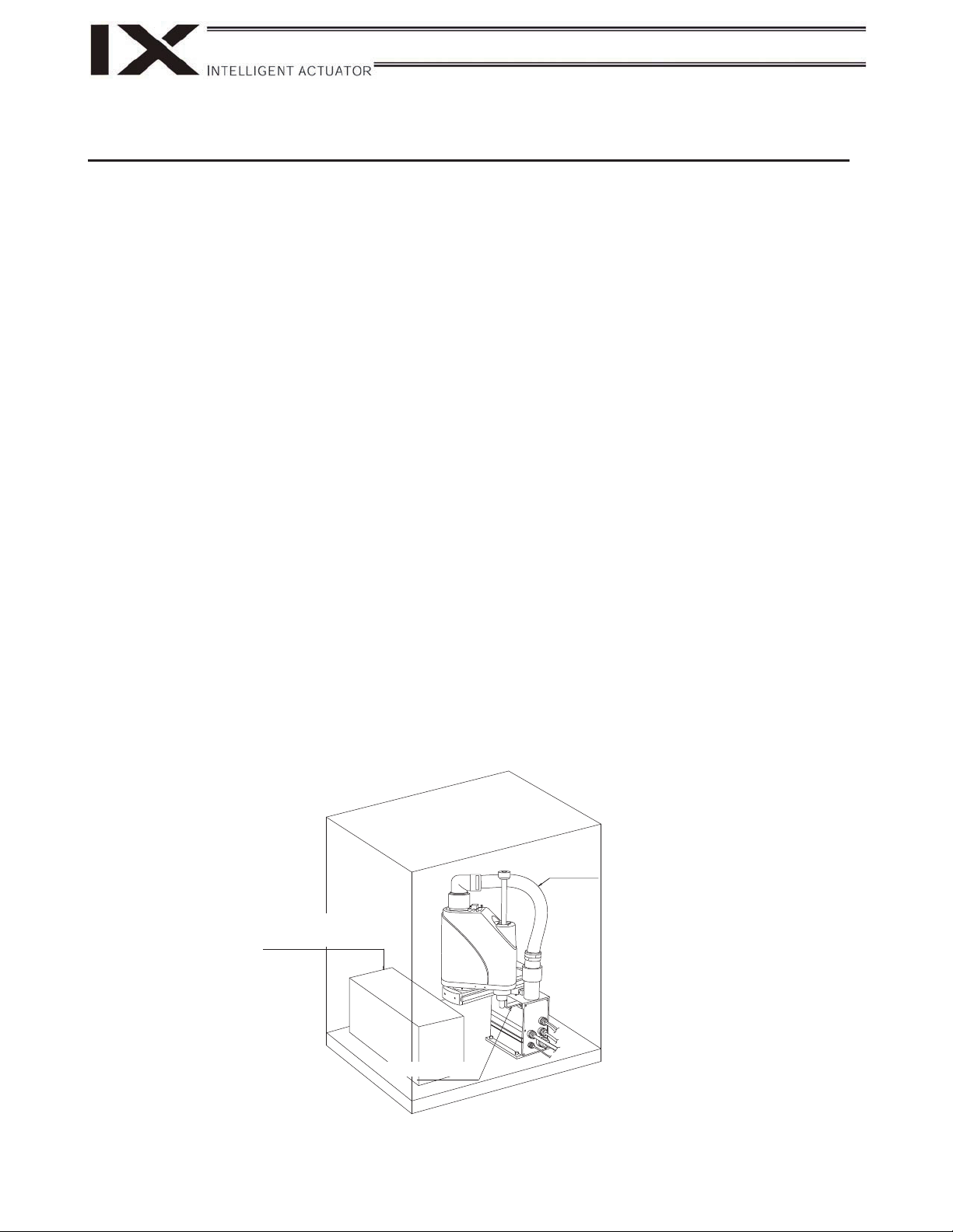
3. Handling of the Carton
Each robot is packed with a controller prior to shipment.
When transporting the carton containing the robot and controller, observe the following items and be careful not
to drop the carton or apply impact due to forcible contact:
• If the carton is heavy, one operator should not attempt to carry it alone.
• Place the carton on a level surface if it is to be left there for a while.
• Do not climb upon the carton.
• Do not place on the carton any heavy object that may cause the carton to deform, or an article whose shape
allows a work part to be concentrated at one point.
[Carton]
Robot
Controller, accessories and
other items (except for the robot)
Arm fixing plate
9
Page 16

CautionWarning
• The robot and controller are very heavy. When transporting the carton containing the robot and controller,
handle it with extra care so as not to drop the carton or apply impact due to forcible contact, as it may cause
injury or damage to the robot or controller.
• Serious injury may result if the carton is dropped onto a person during transportation.
• Never stand below the carton as it is hoisted.
• Use a carrier device with sufficient loading capacity.
• If a machine or method is used that requires specified skills, it must be operated/performed by a person
having the proper qualifications.
4. Handling of Individual Components
The robot and controller are supplied as a set.
Your robot cannot be used with the controller supplied with another robot.
When handling multiple robots, confirm that the serial number on the robot is the same as the serial number on
the controller and be careful not to lose their correct pairings with the controllers.
The robot will not stand on its own after being unloaded from the carton pallet.
Hold it by hand, or place a cushioning material on the floor and place the robot on its side upon the cushion.
10
Page 17
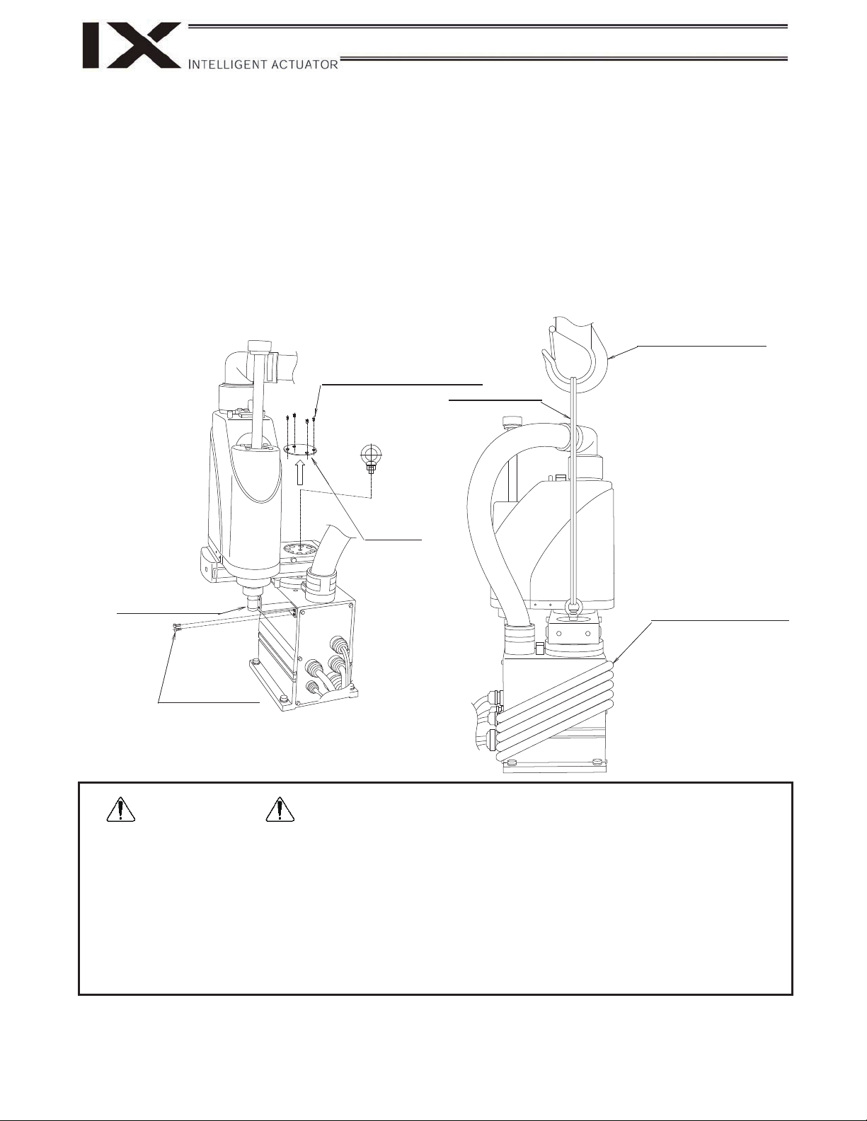
5. Transportation
When transporting the robot, affix the arms using the supplied arm fixing plate. Additionally, wrap the cables
around the base and secure them with gummed tape or other means.
Use a dolly, forklift, crane, or other appropriate equipment for transportation. When transporting the robot, move
it slowly so that it maintains its balance. Also, safeguard the robot against vibration or impact.
When a crane is used, install the supplied eyebolts on the robot for the pass-through of ropes. Install the
eyebolts following removal of the top cover.
Hoisting hook with lock
Cross-recessed countersunk
head screw, M3 x 8
String, rope, etc.
Eyebolt (supplied)
Top cover
Fix with a tie wrap.
HexboltM4x10
Cables
(Wrap around the base.)
WarningDanger
• If the arms and cables remain free, the arms may turn unexpectedly and pinch a hand, or a person may be
tripped by the trailing cables.
• Do not attempt to carry the robot by hand, as it may injure the back. Additionally, an injury may result if the
robot is dropped onto the feet.
• Serious injury may result if a person is caught under a fallen robot during transportation.
• Never stand below the robot as it is hoisted.
• Use a hoist and ropes that can comfortably support the weight of the robot.
• If a machine or method is used that requires specified skills, it must be operated/performed by a person
having the proper qualifications.
11
Page 18
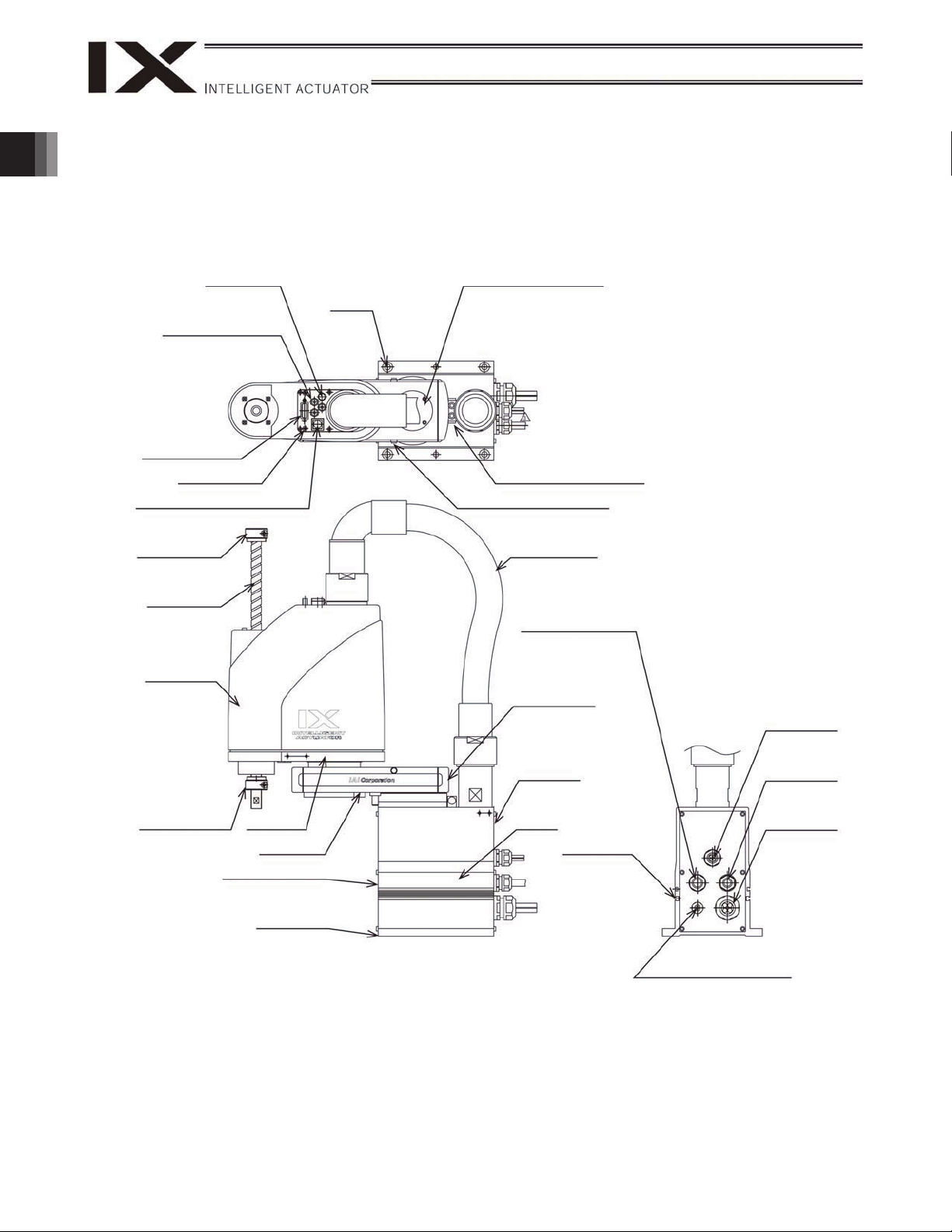
1. Name of Each Part
1.1 Robot
IX-NNN2515H/3515H
4 user piping
(black, red, white;
3 locations)
1. Name of Each Part
User connector
Spacer for user
part installation
BK SW (Brake- release switch)
Mechanical
stopper for axis
3 (vertical axis)
Ball screw
spline shaft
Cover (arm 2)
ALM (indicator)
Reference
surface
Top cover (arm 1)
Mechanical stopper for arm 1
Mechanical stopper for arm 2
Wiring duct
M cable (outside robot)
End cover (arm 1)
Air tubes
(4: 3 pcs.)
Mechanical
stopper for axis
3 (vertical axis)
12
Arm 2
Arm 1
Front panel (base)
Reference
surface
Rear panel
(base)
Base
T-slot for peripheral
installation
(M3, M4)
U cable
(outside robot)
PG cable
(outside robot)
BK power cable
(outside robot)
Page 19
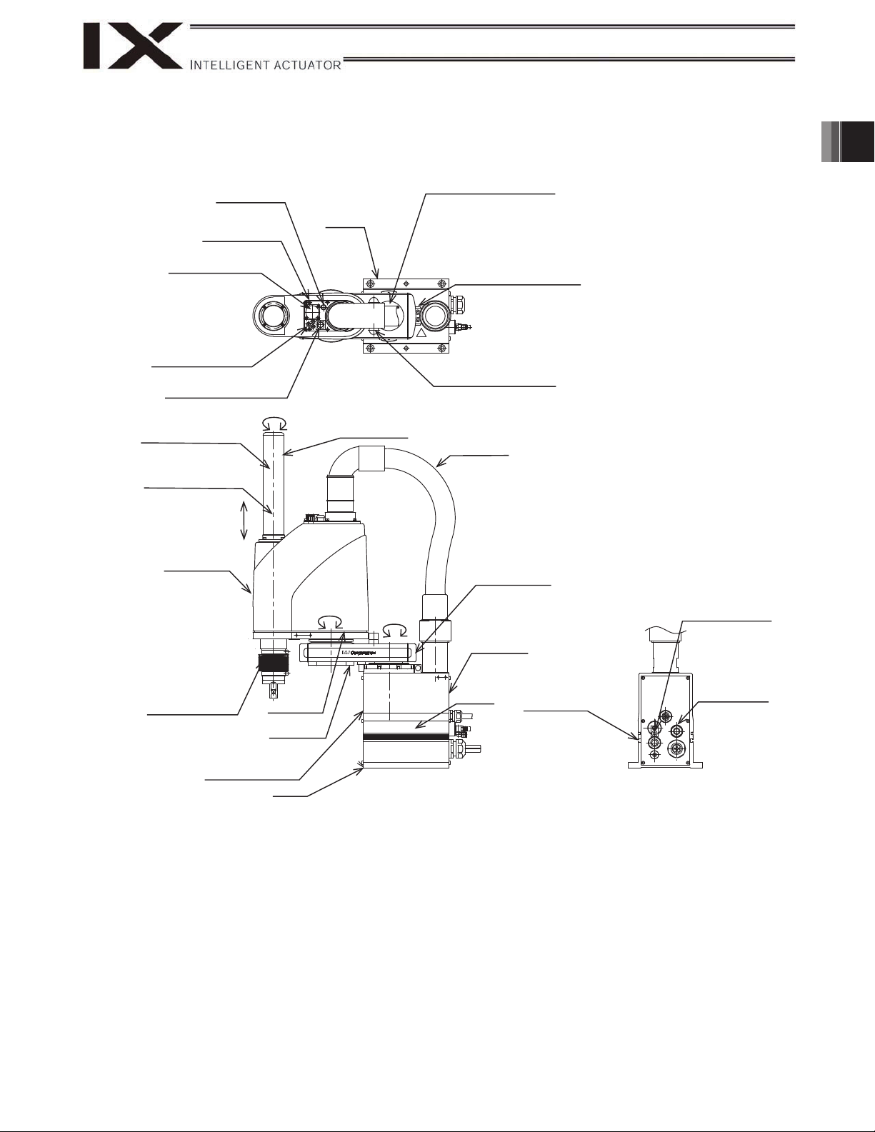
X-NNW2515H/3515H
ALM (indicator)
Spacer for user part
installation
User connector
4 user piping
(black, red, white; 3
locations)
BK SW
(Brake- release switch)
Mechanical stopper for
axis 3 (vertical axis)
<Inside dust cover>
Ball screw spline shaft
<Inside dust cover>
Axis 3
(vertical axis)
Cover (arm 2)
Mechanical stopper for
axis 3 (vertical axis)
<Inside bellows>
Axis 4
(R-axis)
Arm 2
Reference
surface
Duct cover
Axis 2
Axis 1
Top cover (arm 1)
Mechanical stopper for arm 1
3
Mechanical stopper for arm 2
Wiring duct
End cover (arm 1)
Rear panel
(base)
Base
T-slot for peripheral
installation (M3, M4)
1. Name of Each Part
Purge air inlet: Outer
diameter 6
(Inner diameter 8)
Applicable tube: Outer
diameter 12
(Inner diameter 8)
Arm 1
Front panel (base)
Reference surface
13
Page 20
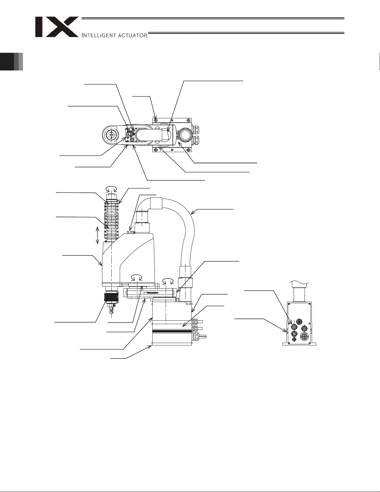
IX-NNC2515H/3515H
4 user piping
(black, red, white; 3 locations)
1. Name of Each Part
User connector
Spacer for user part installation
Mechanical stopper for
axis 3 (vertical axis)
<Inside bellows>
Ball screw spline shaft
<Inside bellows>
(vertical axis)
Cover (arm 2)
ALM (indicator)
Axis 4
(R-axis)
Panel
Axis 3
Reference
surface
Bellows
Panel
Top cover (arm 1)
BK SW
(Brake-release switch)
Mechanical stopper for arm 2
Mechanical stopper for arm 1
Wiring duct
End cover (arm 1)
Mechanical stopper for
axis 3 (vertical axis)
<Inside bellows>
Front panel (base)
Reference surface
Arm 2
Arm 1
Axis 2
Axis 1
Rear panel
(base)
Base
Applicable tube: Outer
diameter 12
(Inner diameter 8)
T-slot for peripheral
installation (M3, M4)
14
Page 21
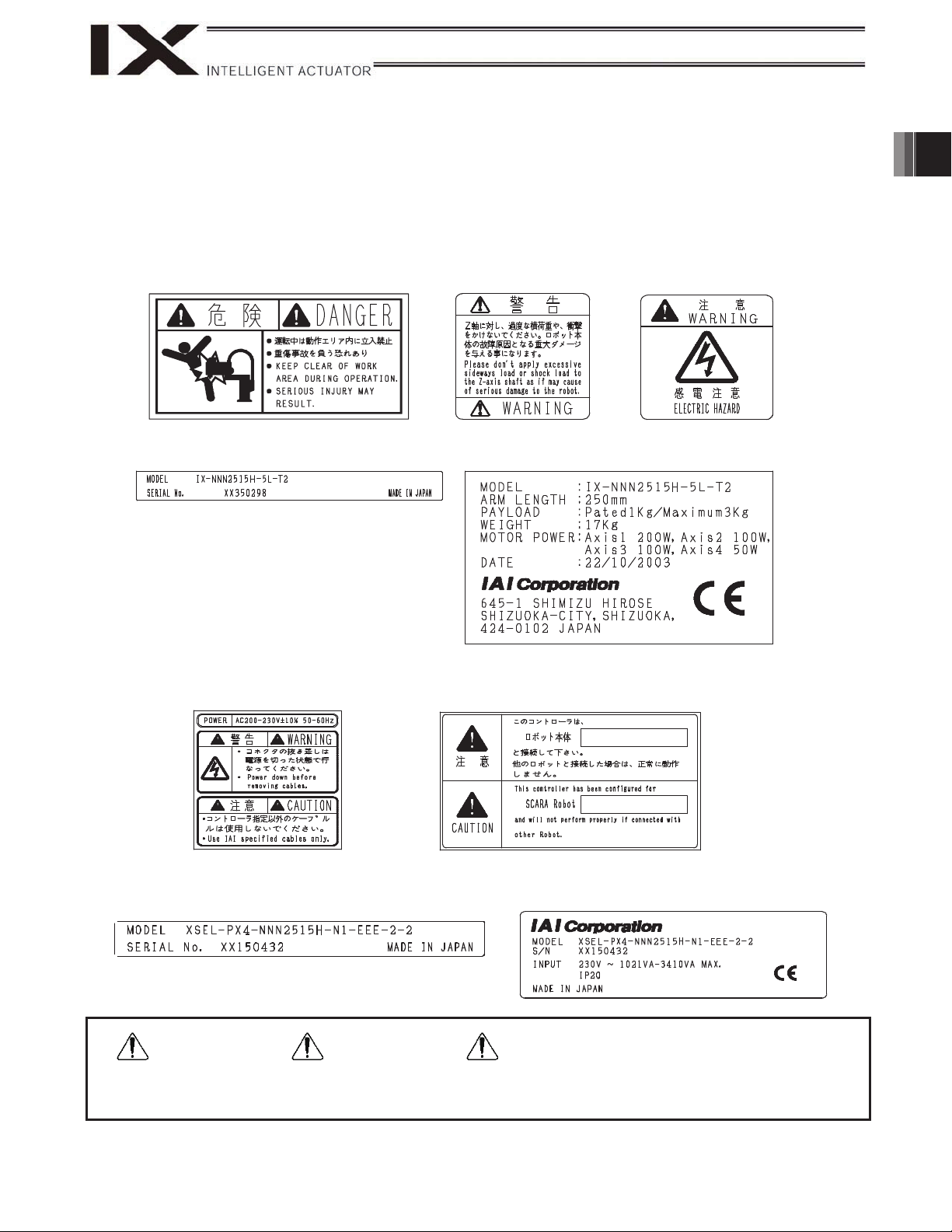
1.2 Labels
The following labels are attached on the robot and controller. Be sure to observe the instructions and cautions
written on the labels to ensure the correct use of the robot/controller.
(1) Labels on the Robot
Prohibition of entry into
the operation area
Robot serial number
(2) Labels on the Controller
Warning on handling of
the vertical axis
CE-certified robot
(Provided only for CE-certified models)
Warning against
electric shock
1. Name of Each Part
Caution/warning on
handling of the controller
Controller serial number
(Other than CE-certified models)
WarningDanger
Failure to observe the cautionary information provided on the labels may result in serious injury or damage
to the robot.
Designation of the connected robot
Controller serial number
(CE-certified models)
Caution
15
Page 22
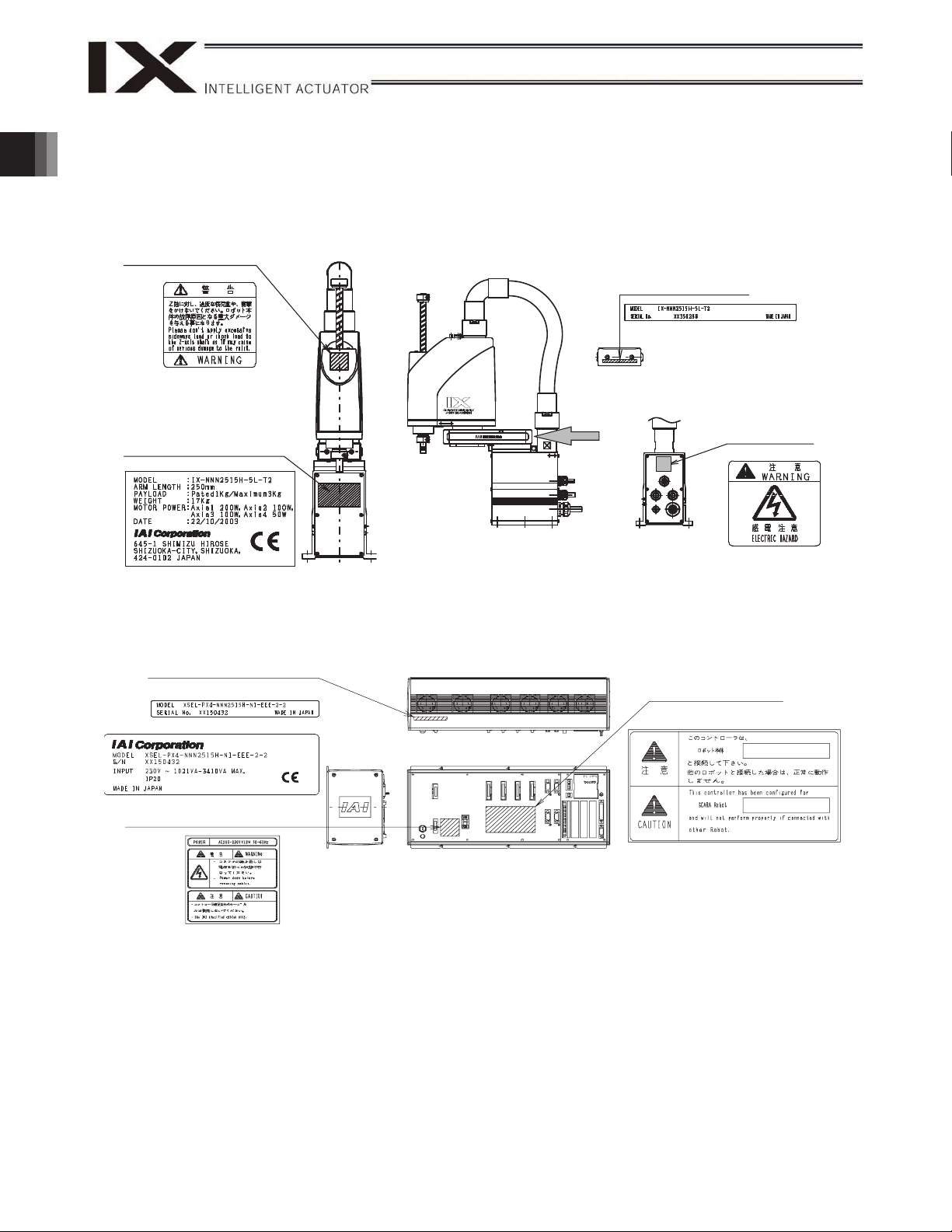
1.3 Label Positions
Label Positions on the Robot
Warning on handling
of the vertical axis
1. Name of Each Part
Robot serial number
View A
CE-certified robot
(Provided only for
CE-certified models)
Label Positions on the Controller
Controller serial number
Other than CE-certified models
CE-certified models
Caution/warning on handling
of the controller
A
Designation of the
connected robot
Warning against
electric shock
16
Page 23
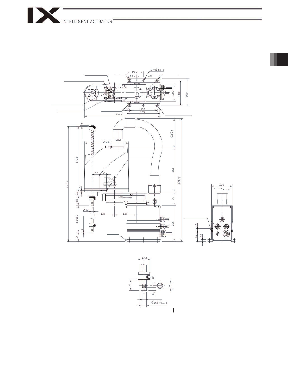
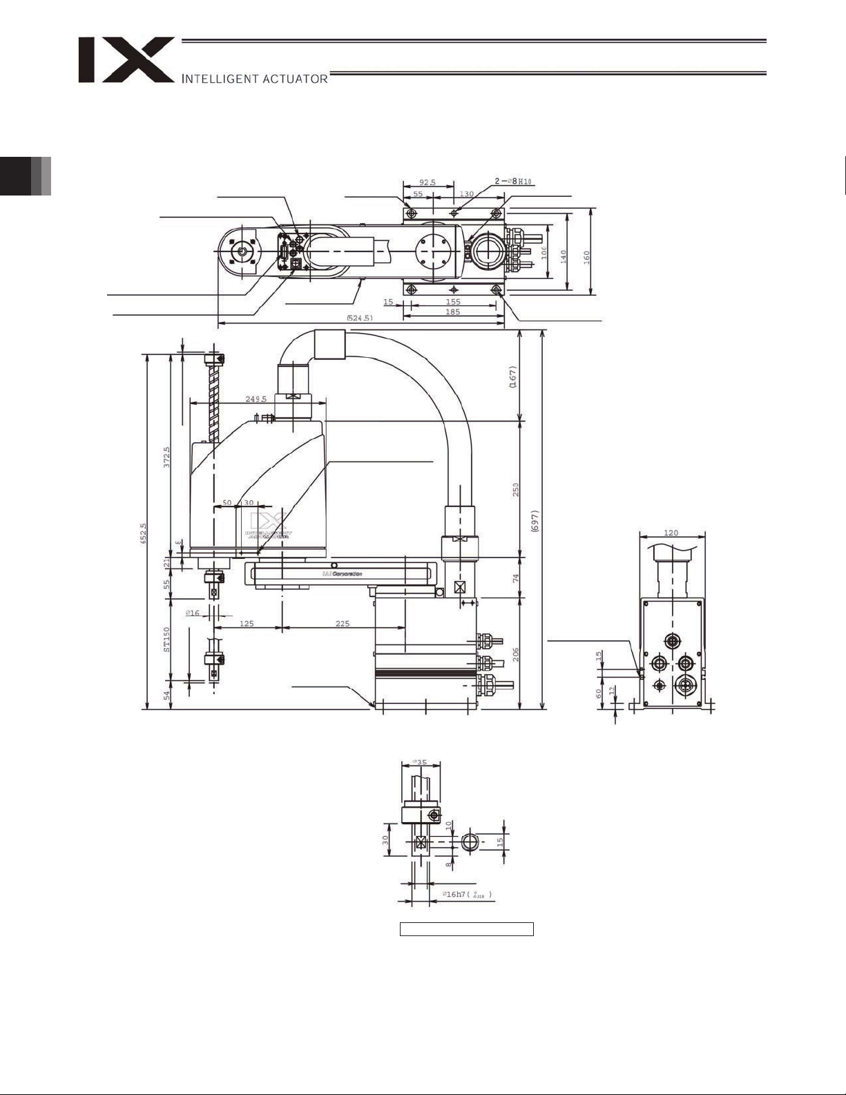
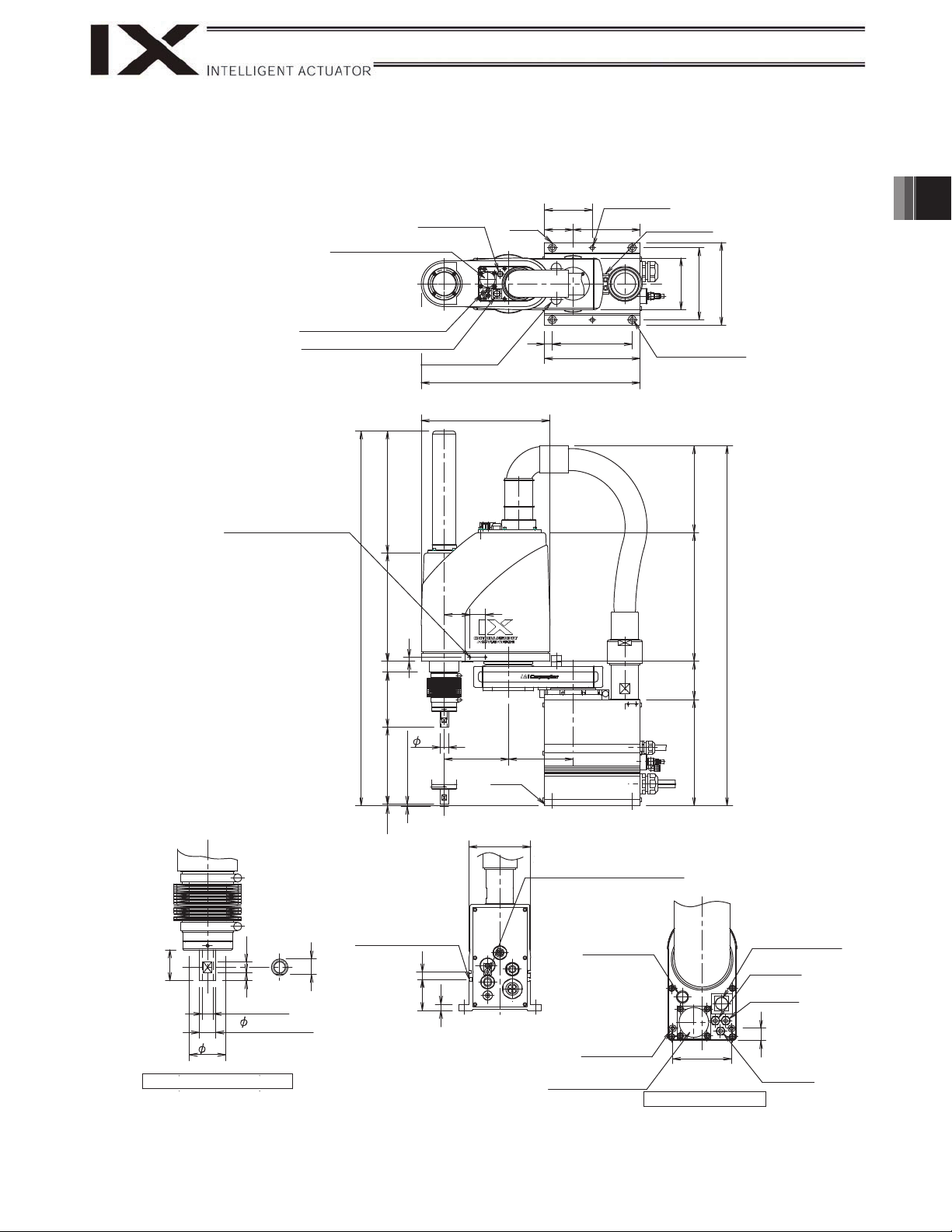
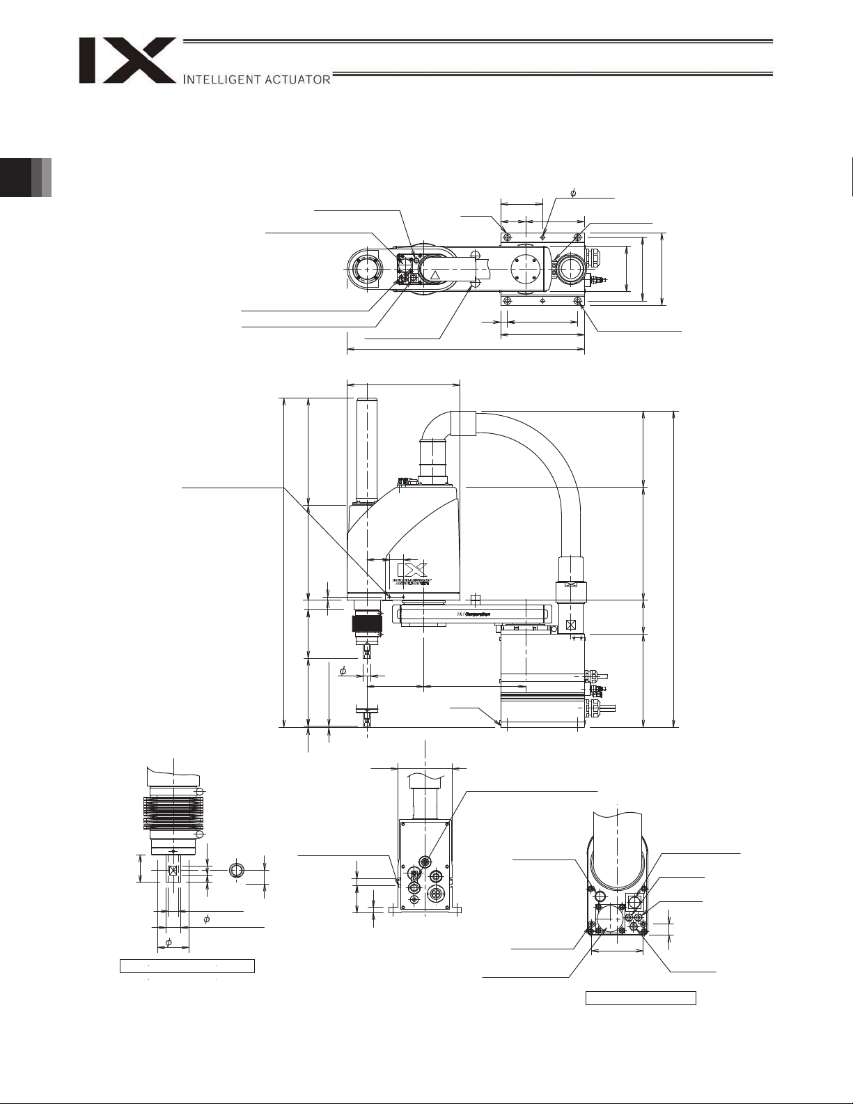
2. External Dimensions
r
IX-NNN2515H (Arm Length 250, Standard Specification)
4 quick ai
(black, red, white; 3 locations)
User connector
(D-sub 15-pin connector)
BK SW
(Brake-release switch)
-tube joint
ALM (indicator)
4 (Mechanical end)
Reference
surface
Arm 2 stopper
Tapped hole for
peripheral installation
(4-M4, depth 12)
Same on opposite
surface
Arm 1 stopper
4-9
16, counterbore depth 0.5
2. External Dimensions
T-slot for peripheral
installation (M3, M4)
(Mechanical end)
Reference
surface
*1: External force applied to the spacers must not
exceed 30 N in the axial direction or 2 Nm in the
rotating direction (for each spacer).
*2: The LED operates only when the user provides a
circuit that receives controller I/O output signal and
supplies 24 VDC to the LED terminal in the user
connector.
11 (inner diameter)
Detailed view of arm end
17
Page 24
IX-NNN3515H (Arm Length 350, Standard Specification)
4 quick air-tube joint
(black, red, white; 3 locations)
User connector
(D-sub 15-pin connector)
BK SW
(Brake-release switch)
2. External Dimensions
4 (Mechanical end)
ALM (indicator)
Arm 2 stopper
Reference surface
Tapped hole for peripheral
installation (4-M4, depth 12)
Same on opposite surface
Arm 1 stopper
4-9
16, counterbore depth 0.5
4 (Mechanical end)
Reference surface
11 (inner diameter)
Detailed view of arm end
T-slot for peripheral
installation (M3, M4)
*1: External force applied to the spacers must not
exceed 30 N in the axial direction or 2 Nm in the
rotating direction (for each spacer).
*2: The LED operates only when the user provides a
circuit that receives controller I/O output signal and
supplies 24 VDC to the LED terminal in the user
connector.
18
Page 25
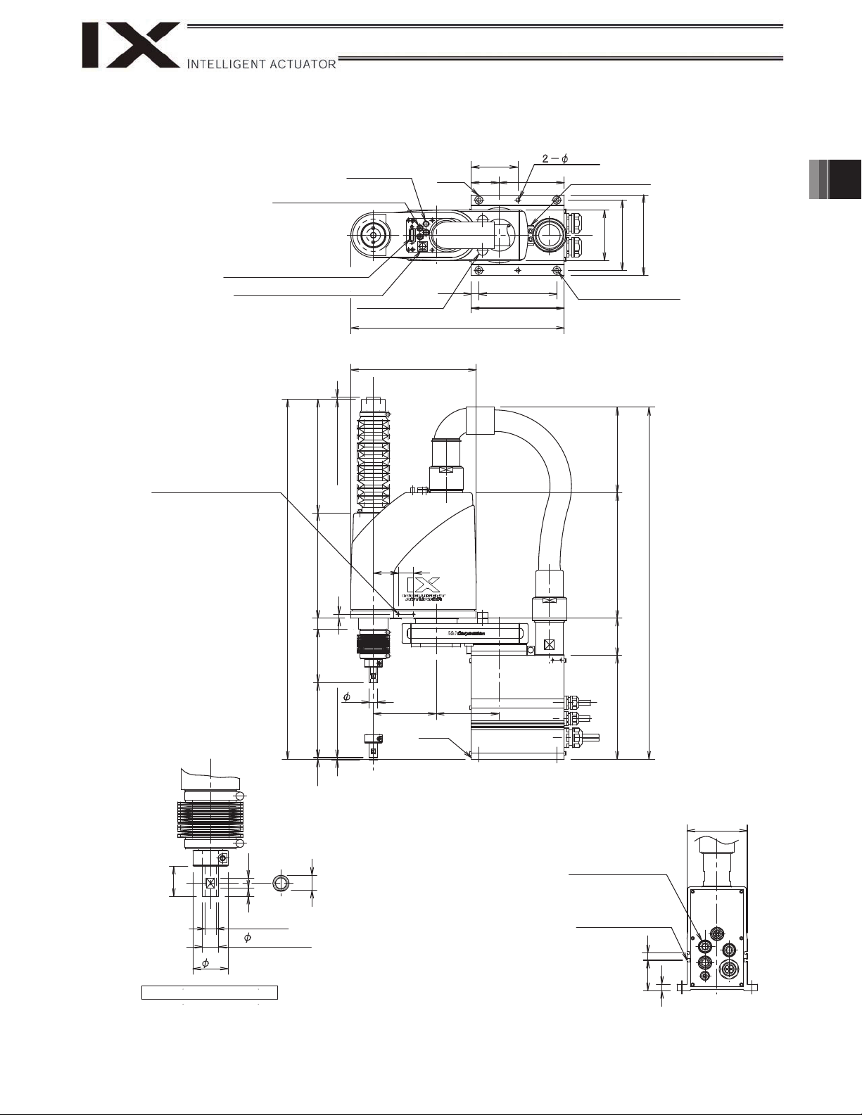
IX-NNW2515H (Arm Length 250, Dust-proof/Splash-proof Specification)
(
)
ALM (indicator)
User connector
4 quick air-tube joint
(black, red, white; 3 locations)
BK SW (Brake-release switch)
Arm 2 stopper
249.5
Reference
surface
(424.5)
92.5
55 130
15
155
185
2-8H10
Arm 1 stopper
001
041
061
4-9
16, counterbore depth 0.5
2. External Dimensions
Tapped hole for peripheral
installation
Same on opposite surface
*1: External force applied to the spacers must not
exceed 30 N in the axial direction or 2 Nm in the
rotating direction (for each spacer).
*2: The LED operates only when the user provides a
circuit that receives controller I/O output signal and
supplies 24 VDC to the LED terminal in the user
connector.
03
4-M4, depth 12
51
8 01
11 (inner diameter)
16h7(
0
-0.018
)
35
Detailed view of arm end
732
727
8
12
5.601051TS5.2 012
16
4 (Mechanical end)
T-slot for peripheral
installation (M3, M4)
5106
)5.861(
30
50
125
125
Reference
surface
120
Air supply port for air purge
)5.896(
602 47 052
External diameter 6
(Internal diameter 4)
BK SW
ALM (Red LED)
(Brake-release switch)
4(black)
quick joint
21
Spacer for user part installation
Height 10, M4, depth 5
57
User connector
(15-pin connector)
4(white)
quick joint
21
4(red)
quick joint
Detailed view of panel
19
Page 26
IX-NNW3515H (Arm Length 350, Dust-proof/Splash-proof Specification)
(
)
(
)
2. External Dimensions
Tapped hole for peripheral
installation
Same on opposite surface
*1: External force applied to the spacers
must not exceed 30 N in the axial
direction or 2 Nm in the rotating
direction (for each spacer).
*2: The LED operates only when the user
provides a circuit that receives
controller I/O output signal and
supplies 24 VDC to the LED terminal
in the user connector.
User connector
4 quick air-tube joint
black, red, white; 3 locations
BK SW (Brake-release switch)
4-M4, depth 12
727
ALM (Alarm indicator
Arm 2 stopper
732
0125.2 051TS 5.601 12
50
8
16
)
249.5
30
125
Reference surface
3
(524.5)
225
Reference surface
55 130
15
92.5
155
185
2- 8H10
Arm 1 stopper
001
4-9
16, counterbore depth 0.5
041
061
)5.861(
052
)5.896(
602 47
4 (Mechanical end)
120
Air supply port for air purge
External diameter 6
(Internal diameter 4)
BK SW
(Brake-release switch)
4(black)
quick joint
4(bwhite)
quick joint
21
4(red)
quick joint
018
03
11 (inner diameter)
16h7(
0
-0.018
35
Detailed view of arm end
51
)
T-slot for peripheral
installation (M3, M4)
06 51
ALM (Red LED)
21
Spacer for user part
Height 10, M4, depth 5
installation
57
User connector
(15-pin connector)
Detailed view of panel
20
Page 27
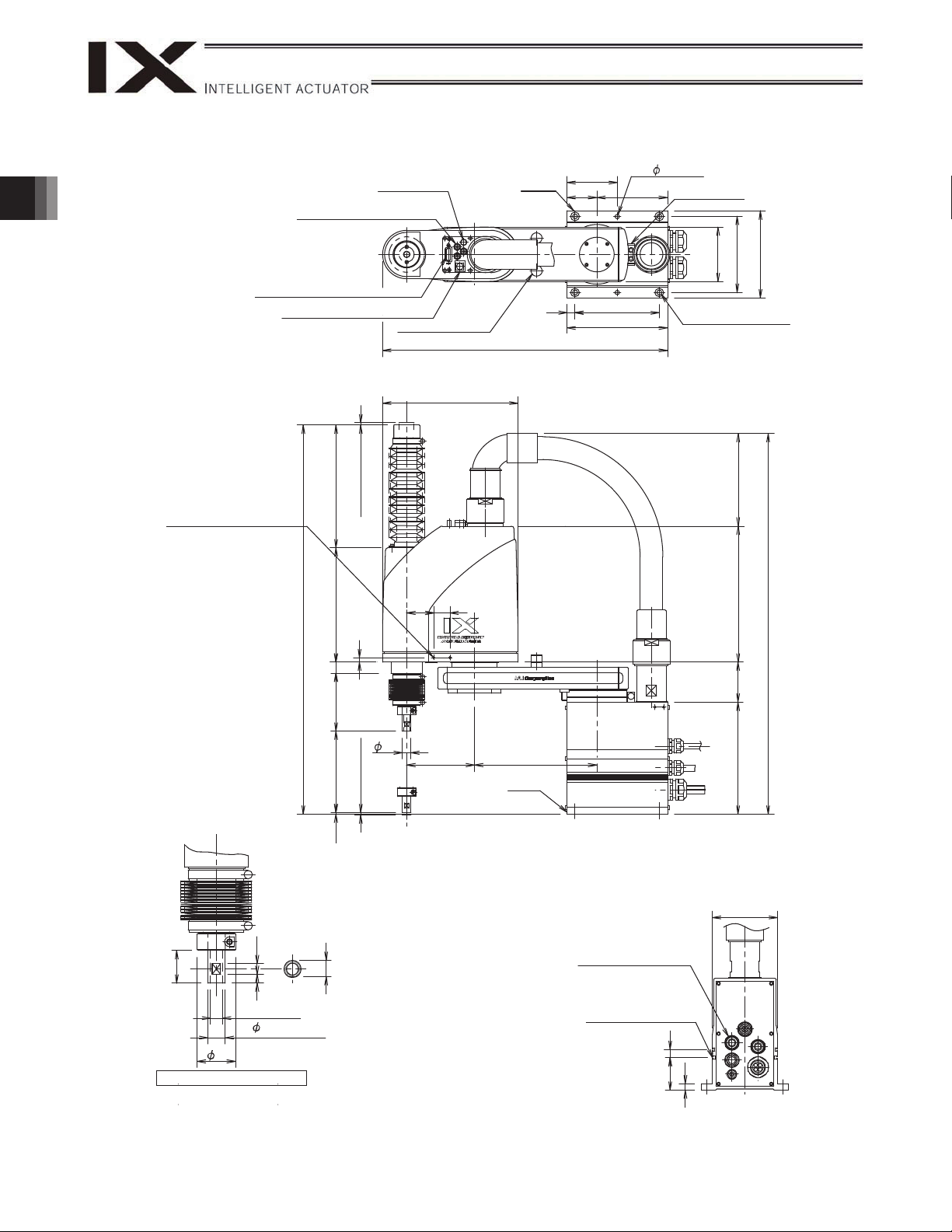
IX-NNC2515H (Arm Length 250, Clean Room Specification)
4 quick air-tube joint
(black, red, white; 3 locations)
User connector
(D-sub 15-pin connector)
BK SW (Brake-release switch)
Tapped hole for peripheral
installation (4-MA, depth 12)
Same on opposite surface
ALM (indicator)
Arm 2 stopper
4 (Mechanical end)
249.5
Reference
surface
15
(424.5)
92.5
55 130
155
185
8H10
Arm 1 stopper
001
041
061
4-
9
16, counterbore depth 0.5
)071(
2. External Dimensions
03
8 01
11 (inner diameter)
16h7 (
35
Detailed view of arm end
617
0
-0.018
30
50
)007(
8
12
5.601051TS5.2 012 622
16
Reference
surface
125
Applicable tube: Outer
diameter 12
(Inner diameter 8)
125
4 (Mechanical end)
51
T-slot for peripheral
installation (M3, M4)
)
602 47 052
120
21
06 51
21
Page 28
IX-NNC3515H (Arm Length 350, Clean Room Specification)
2. External Dimensions
Tapped hole for peripheral
installation (4-MA, depth 12)
Same on opposite surface
4 quick air-tube joint
(black, red, white; 3 locations)
User connector
(D-sub 15-pin connector)
BK SW (Brake-release switch)
4 (Mechanical end)
6220125.2 051TS 5.601 12
617
ALM (indicator)
Arm 2 stopper
249.5
30
50
Arm 2 stopper
Reference
surface
(524.5)
92.5
55 130
15
155
185
2- 8H10
Arm 1 stopper
001
4-9
16, counterbore depth 0.5
041
061
)071(
052
)007(
03
8 01
11 (inner diameter)
16h7(
35
Detailed view of arm end
0
-0.018
8
16
4 (Mechanical end)
125
225
Reference
surface
602 47
120
Applicable tube: Outer
diameter 12
51
(Inner diameter 8)
T-slot for peripheral
installation (M3, M4)
)
21
06 51
22
Page 29
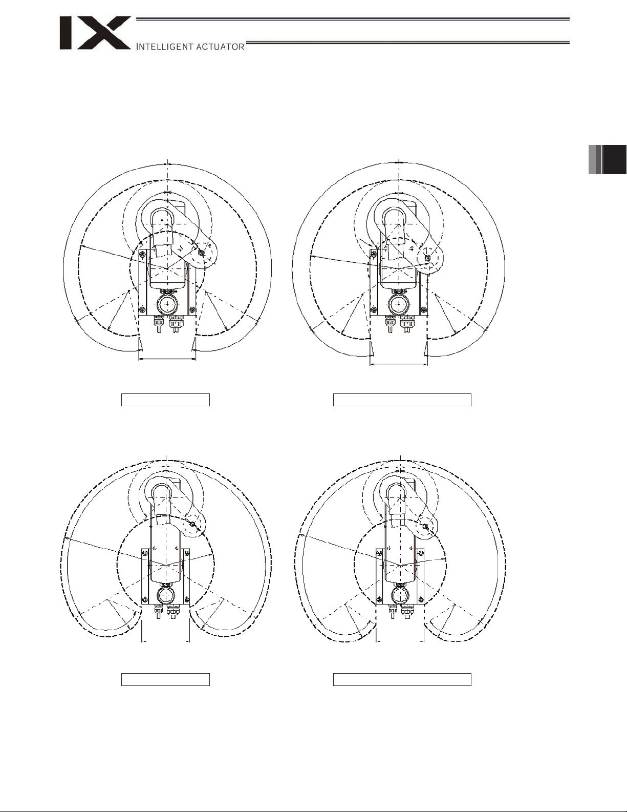
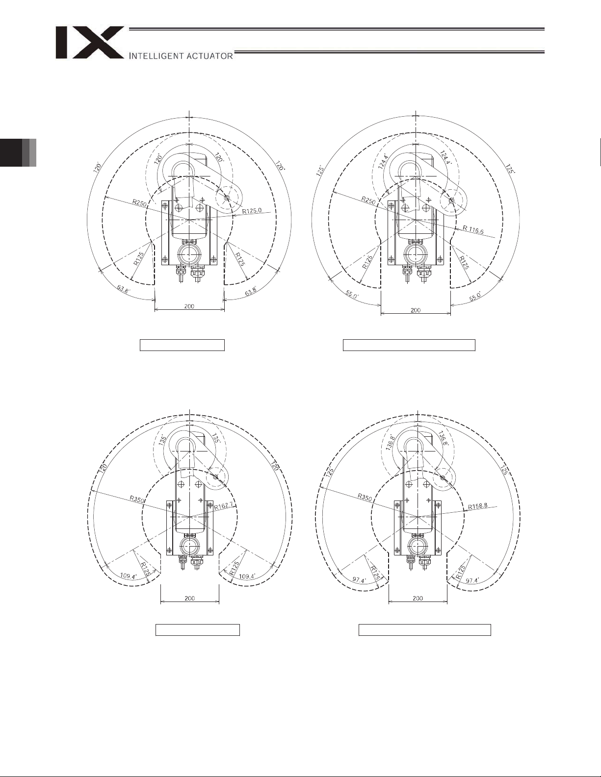
3. Robot Operation Area
IX-NNN2515H (Arm Length 250, Standard Specification)
1
1
3
0
0
3
0
0
2
2
1
1
7
7
3
3
.
.
1
1
3
1
1
R
R
2
2
5
5
0
0
5
5
2
2
1
1
R
R
160
160
3
0
0
7
7
5.
5.
0
0
1
1
R
R
R
R
1
1
2
2
Area of prohibited entry Area of prohibited entry
1
1
2
2
0
0
5
5
1
1
.
.
73
73
5
5
2
2
1
1
3. Robot Operation Area
1
1
1
3
3
9
5
5
.
.
139
139
R
R
1
1
7
7
.
.
5
5
R
R
2
2
5
5
0
0
5
5
2
2
1
1
R
R
6
6
5
5
.
.
3
3
160
160
9
.
.
5
5
5
5
.
.
6
6
8
8
R
R
R
R
1
1
2
2
5
5
1
2
2
5
5
3
3
.
.
5
5
6
6
Movement range
IX-NNN3515H (Arm Length 350, Standard Specification)
1
160
160
1
3
3
5
5
1
1
2
2
0
0
7
7
.
.
2
2
6
6
1
1
R
R
5
5
2
2
1
1
R
R
5
5
3
3
1
1
0
0
2
2
1
1
R
R
3
3
5
5
0
0
R
R
1
1
2
2
5
5
126.8 126.8
126.8 126.8
Area of prohibited entry Area of prohibited entry
Movement range
Mechanical stopper position
5
5
.
.
9
9
3
3
1
1
5
5
2
2
1
1
R
R
3
3
5
5
0
0
R
R
1
1
2
2
5
5
111.6
111.6
160
160
Mechanical stopper position
1
1
3
3
9
9
.
.
5
5
1
1
2
2
5
5
2
2
.
.
3
3
5
5
1
1
R
R
5
5
2
2
1
1
R
R
111.6
111.6
23
Page 30
3. Robot Operation Area
IX-NNW2515H (Arm Length 250, Dust-proof/Splash-proof Specification), IX-NNC2515H (Arm Length 250, Clean
Room Specification)
Area of prohibited entry Area of prohibited entry
Movement range
Mechanical stopper position
IX-NNW3515H (Arm Length 350, Dust-proof/Splash-proof Specification), IX-NNC3515H (Arm Length 350, Clean
Room Specification)
Area of prohibited entry Area of prohibited entry
24
Movement range
Mechanical stopper position
Page 31

y
)
)
)
(
)
4. Wiring Diagram
4.1 Layout Drawing
IX-NNN2515H/3515H
Servo motor for
axis 2 (arm 2)
Socket
DF11-8DS-2C (Hirose)
PG2
M2
Socket
U cable (inside robot)
DWG No. 1069443*
DWG No. 1069442*
Inside arm 2
DWG No. 1069444*
PG cable (inside robot)
M cable (inside robot)
cable
Flexible
Servo motor with
brake for axis 3
(Z-axis)
PG3
172159-1 (Tyco
Electronics AMP
D-sub connector
XM2D-1501
(Omron)
User
Connector
ALM
BK SW
Alarm LED
Electromagnetic
brake for axis 4
(R-axis)
PG4
M4
172169-1
(Tyco Electronics
AMP)
(Optional)
BK4
Plug
FG (to D-sub housing)
Socket DF3-2S-2C (Hirose)
172165-1
(Tyco Electronics
AMP)
Air joint, black (4)
Air joint, red (4)
Air joint, white (4)
LED
D-sub connector for user wiring (15-pin, socket)
Brake-release switch for axes 3/4 (Z/R-axes)
BK
Socket DF3-3S-2C (Hirose)
Hirose
Plug
172166-1
(Tyco Electronics
AMP)
Servo motor for
axis 4 (R-axis)
M3
BK3
Socket
172157-1 (Tyco
Electronics AMP
Plug
4. Wiring Diagram
Socket
DF11-10DS-2C
Plug
DF11-10DEP-2C
DWG No. 1068765*
(Hirose)
FG (To base)
Air joint, black (4)
Air joint, red (4)
U14
U15
Air joint, white (4)
FG
LED +24V
LED G24V
Connector
XAP-02V-1 (JST)
U13
Socket
172159-1
Servo motor for
co Electronics AMP
T
Cable fix cap (Capcon)
axis 1 (arm 1)
M1M2M3
M cable (outside robot)
M1M2M3
DWG No. 1068763*
OUTPG1
M4
INPG1
PG cable
(outside robot)
Plug
GIC2,5/4-STF-
7.62 (Phoenix
Contact)
M4
PG1
OUTPG4
BK4
OUTPG2
OUTPG3
INPG2
INPG3
PG2
PG3
BK3
SW
Board
UB
UA
INPG4
BAT 1
BAT 2
BAT 3
Female connector
HIF 3BA-10D-2.54C
(Hirose)
Dedicated batteries for IX: AB-3
DWG No .
1068764*
PG4
24 VDC
BAT 4
U cable (outside robot)
BK power cable (outside robot)
+24 V
U1U2U3
G24 V
The 24 V power supply for I/O circuits used on the secondary side (low-voltage side) cannot be shared.
Wiring/Piping Diagram (Arm Length: 250/350)
4. Wiring Diagram
Controller Inside base
Housing
KEC-15P
Contact
JK-SP2140 (JST)
terminals
Brake power
terminals
User wiring
Notes
(1) The actual layout of board connectors varies from this drawing.
(2) Since the brake power circuit is provided on the primary side (high-voltage side), a dedicated 24 V power supply is required for this circuit.
(3) To operate the alarm LED, the user must provide a circuit that uses the controller I/O output signal.
25
Page 32

U
M4
FG
LED G24V
LED +24V
U15
U14
U13
U3
U2
U1
4. Wiring Diagram
Controller
M1
M2
M3
M4
PG1
PG2
PG3
PG4
User wiring terminals
PG cable (outside robot)
+24V
M cable (outside robot)
G24V
Air joint
Black (4), Red (4), White (4)
U cable (outside robot)
Brake power terminals
B
LED
UA
FG
M cable (inside robot)
Flexible cable
U cable (inside robot)
PG cable (inside robot)
INPG1
M1M2M3
OUTPG1
BAT1
BAT2
BAT3
INPG2
INPG3
INPG4
BAT4
24 VDC
Board
BK4
BK3
SW
OUTPG2
OUTPG3
OUTPG4
26
1-axis motor
Air tubes
PG cable (inside robot)
M cable (inside robot)
Air tubes
1-axis encoder
U cable (inside robot)
2-axis motor
2-axis encoder
BK4
BK3
M4
PG4
M3
PG3
M2
LED
D-sub connector for user wiring
(15-oin, socket)
Alarm LED
Air joint
Black (4), Red 4), White (4)
Brake-release switch for axes 3/4
(Z/R-axes)
PG2
3-axis brake
3-axis motor
3-axis encoder
4-axis brake
4-axis motor
4-axis encoder
Page 33

IX-NNW2515H/3515H
)
DWG No. 1068795*
DWG No. 1068794*
Inside arm 2
DWG No. 1068796*
Servo motor for
axis 2 (arm 2)
Socket
DF11-8DS-2C (Hirose)
M cable (inside robot)
U cable (inside robot)
PG cable (inside robot)
Flexible
cable
Servo motor with
brake for axis 3
(Z-axis)
Socket
172159-1 (Tyco
Electronics AMP)
Servo motor for
axis 4 (R-axis)
Socket
172157-1 (Tyco
Electronics AMP)
Plug
172169-1
Electromagnetic
brake for axis 4
(R-axis)
(Optional)
Plug
(Tyco Electronics
AMP)
FG (to D-sub housing)
Waterproof connector, 15 pin
Socket DF3-2S-2C (Hirose)
172165-1
(Tyco Electronics
AMP)
Alarm LED
Air joint, black (4)
Air joint, red (4)
Air joint, white (4)
D-sub connector for user wiring (15-pin, socket)
Plug
(Hirose)
Brake-release switch for axes 3/4 (Z/R-axes)
Plug
172166-1
(Tyco Electronics
AMP)
Socket DF3-3S-2C (Hirose)
Socket
DF11-10DS-2C (Hirose)
Air supply port ffor air purge
(tube diameter 5)
4. Wiring Diagram
Inside base
Servo motor for
axis 1 (arm 1)
Board
Air joint, black (4)
Air joint, red (4)
Socket
172159-1
Cable fix cap (Capcon)
Connector
(Tyco Electronics AMP)
outside robot
Female connector
HIF 3BA-10D-2,54C
PG cable
DWG No. 1068763*
M cable (outside robot)
Plug
(Phoenix Contact)
(Hirose)
U cable (outside robot)
BK power cable (outside robot)
Dedicated batteries for IX: AB-3
DWG No .
1068764*
XAP-02V-1 (JST)
DWG No. 1068765*
Air joint, white (4)
The 24 V power supply for I/O circuits used on the secondary side (low-voltage side) cannot be shared.
Controller
Wiring/Piping Diagram (Arm Length: 250/350)
Housin
Contact
terminals
Brake power
terminals
User wiring
Notes
(1) The actual layout of board connectors varies from this drawing.
(2) Since the brake power circuit is provided on the primary side (high-voltage side), a dedicated 24 V power supply is required for this circuit.
(3) To operate the alarm LED, the user must provide a circuit that uses the controller I/O output signal.
(4) The user connector is waterproof.
(5) FG is connected to pin 16 of the connector.
27
Page 34

User wiring
r
r
r
r
-
r
r
r
r
(
)
terminals
Controller
PG cable (outside robot)
4. Wiring Diagram
Flexible
cable
U cable
(outside robot)
M cable
(outside robot)
M cable (inside robot)
U cable (inside robot)
PG cable (inside robot)
axis encode
1-axis moto
1
Brake power
supply terminal
Board
Air supply port for air purge
Air joint
Black (4), Red (4), White (4)
Air tubes
PG cable
(inside robot)
M cable (inside robot)
Air tubes
U cable (inside robot)
axis encode
2-axis moto
2
axis encode
3-axis brake
3-axis moto
3
axis encode
4-axis brake
4-axis moto
4
Z/R-axes
Alarm LED
Waterproof connector, 15 pin
Brake-release switch for axes
3/4
Air joint
Black (4), Red (4), White (4),
28
Page 35

IX-NNC2515H/3515H
Servo motor for
axis 2 (arm 2)
Alarm LED
Electromagnetic
brake for axis 4
Servo motor with
brake for axis 3
(Z-axis)
Servo motor for
axis 4 (R-axis)
Air joint, black (4)
Air joint, red (4)
Air joint, white (4)
FG (to D-sub housing)
4. Wiring Diagram
Inside arm 2
PG cable (inside robot)
M cable (inside robot)
U cable (inside robot)
cable
Flexible
Servo motor for
axis 1 (arm 1)
Board
Brake-release switch for axes 3/4 (Z/R-axes)
D-sub connector for user wiring (15-pin, socket)
Quick suction joint
(tube diameter 12)
FG (To base)
Air joint, black (4)
Air joint, red (4)
Air joint, white (4)
Cable fix cap (Capcon)
M cable (outside robot)
Controller Inside base
Wiring/Piping Diagram (Arm Length: 250/350)
PG cable (outside robot)
Dedicated batteries for IX
BK power cable (outside robot)
U cable (outside robot)
terminals
Brake power
terminals
User wiring
Notes
(1) The actual layout of board connectors varies from this drawing.
The 24 V power supply for I/O circuits used on the secondary side (low-voltage side) cannot be shared.
(2) Since the brake power circuit is provided on the primary side (high-voltage side), a dedicated 24 V power supply is required for this circuit.
(3) To operate the alarm LED, the user must provide a circuit that uses the controller I/O output signal.
29
Page 36

4.2 Machine Harness Wiring Table
IX-NNN2515H/3515H
(1) PG cables (inside robot) DWG No. 1069443*
4. Wiring Diagram
Tube
symbol
OUT PG2 OUT PG3 OUT PG4
Base end Arm end
Pin
Connector
Mini Universal
MATE-N-LOK
plug housing
172169-1 (by
Tyco
Electronics
AMP)
Same as above
Same as above Same as above
Signal
No.
BAT+
1
BAT-
2
SD
3
-SD
4
Vcc
5
GND
6
Shield
7
8
9
1
BAT+
BAT-
2
SD
3
-SD
4
Vcc
5
GND
6
Shield
7
8
9
1
BAT+
BAT-
2
3
SD
-SD
4
Vcc
5
GND
6
7
Shield Shield
8
9
Connection
Pin
No
1
2
3
4
5
6
7
8
9
1
2
3
4
5
6
7
8
9
1
2
3
4
5
6
7
8
9
Signal
BAT+
BAT-
SD
-SD
Vcc
GND
Shield
BAT+
BAT-
SD
-SD
Vcc
GND
Shield
BAT+
BAT-
SD
-SD
Vcc
GND
Connector
Double-brazed
crimp socket
DF11-8DS-2C
(by Hirose
Electric)
Same as above
Tube
symbol
PG2PG3PG4
ID No.
Red
White
Red
White
Red
White
Green
Red
White
Red
White
Red
White
Green
Red
White
Red
White
Red
White
Green
Cable
AWG22
(0.3 mm
shielded
cable
2
)
(2) M cables (inside robot) DWG No. 1069442*
Base end Arm end
Tube
symbol
M2
M3
M4
BK3
BK4
Connector
Mini Universal
MATE-N-LOK
plug housing
172167-1 (by
Tyco Electronics
AMP)
Same as above
Same as above
Mini Universal
MATE-N-LOK plug
housing 172165-1
(by Tyco
Electronics AMP)
Same as above
Signal
U
V
W
C G
U
V
W
C G
U
V
W
C G
BK-
BK+
BK-
BK+
Pin
No.
1
2
3
4
1
2
3
4
1
2
3
4
1
2
1
2
Connection
Pin
No
1
2
3
4
1
2
3
4
1
2
3
4
1
2
1
2
30
Signal
Mini Universal
U
MATE-N-LOK
V
panel installation
socket housing
W
172159-1 (by Tyco
Electronics AMP)
C G
U
V
W
C G
U
V
W
C G
Mini Universal
BK-
MATE-N-LOK
BK+
panel installation
socket housing
172157-1 (by Tyco
Electronics AMP)
BK-
BK+
Connector
Same as above
Same as above
Same as above
Tube
symbol
U
V
W
C G
U
V
W
C G
U
V
W
C G
BK-
BK+
BK-
BK+
ID No. Cable
1
2
3
4
5
6
7
Flexible
8
cable
9
10
11
12
13
14
15
16
16 X
AWG18
Page 37

(3) UA and UB cables (outside robot) DWG No. 1069444*
Base end Arm end
Tube
symbol
Connector
Double-brazed
relay plug DF1110DEP-2C (by
Hirose Electric)
Same as above
Mini Universal MATEN-LOK plug housing
172166-1 (by Tyco
Electronics AMP)
Un-isolated terminal
(Y type) F0.3-4
Signal
Pin
No.
Connection
Pin
No.
Signal
Connector
D-sub connector
XM2D-1501 (by
Omron)
Un-isolated terminal
(round type) F0.3-3
Single-brazed
crimp socket DF32S-2C (by Hirose
Electric)
Single-brazed
crimp socket DF33S-2C (by Hirose
Electric)
Tube
symbol
ID No.
Black
White
Green
Red
Black
White
Black
RED
Cable
AWG22
(0.3 mm
shielded
cable
4. Wiring Diagram
2
)
31
Page 38

IX-NNW2515H/3515H
A
AMP)
A
(1) PG cables (inside robot) DWG No. 1068795*
Base end Arm end
Tube
symbol
Connector
Mini Universal
MATE-N-LOK
plug housing
172169-1 (by
Tyco Electronics
MP)
Signal
Shield
Pin
No.
Connection
Pin
No.
Signal
Shield
Connector
Double-brazed
crimp socket
DF11-8DS-2C (by
Hirose Electric)
Tube
symbol
ID No.
1R/sky blue
1B/sky blue
1R/pink
1B/pink
1R/grass green
1B/grass green
Green
Cable
4. Wiring Diagram
(2) M cables (inside robot) DWG No. 1068794*
Tube
symbol
Same as above
Same as above
Base end Arm end
Connector
Mini Universal
MATE-N-LOK plug
housing 172167-1
(by Tyco
Electronics AMP)
Shield
Shield
Signal
Pin
No.
Connection
Pin
No.
Shield
Shield
Signal
Same as above
Same as above
Connector
Mini Universal
MATE-N-LOK panel
installation socket
housing 172159-1
(by Tyco Electronics
Tube
symbol
1R/orange
1B/orange
1R/gray
1B/gray
2R/sky blue
2B/sky blue
Green
2R/pink
2B/pink
2R/grass green
2B/grass green
2R/orange
2B/orange
Green
ID No.
Flexible
cable
10p x
AWG26
Shielded
cable
Cable
Same as above
Same as above
Mini Universal
MATE-N-LOK plug
housing 172165-1
(by Tyco
Electronics AMP)
Same as above
32
Same as above
Same as above
Mini Universal
MATE-N-LOK panel
installation socket
housing 172157-1
(by Tyco Electronics
MP)
Same as above
Flexible
cable
16 x
AWG18
Page 39

(3) UA and UB cables (outside robot) DWG No. 1068796*
Base end Arm end
Tube
symbol
Connector
Double brazed
extension plug
DF11-10DEP-2C
(by Hirose
Electric)
Mini Universal MATEN-LOK plug housing
172166-1 (by Tyco
Electronics AMP)
Bare terminal
(Y type) F0.3-4
Signal
Pin
No.
Connection
Pin
No.
Signal
Connector
D-sub connector
XM2D-1501 (by
Omron)
Single-brazed
crimp socket
DF3-2S-2C (by
Hirose Electric)
Single-brazed
crimp socket
DF3-3S-2C (by
Hirose Electric)
Tube
symbol
ID No. Cable
1R/sky blue
1B/sky blue
1R/pink
1B/pink
1R/grass green
1B/grass green
1R/orange
1B/orange
1R/gray
1B/gray
2R/sky blue
2B/sky blue
2R/pink
2B/pink
2R/grass green
Green
2B/grass green
2R/orange
2B/orange
2R/gray
2B/gray
Flexible
cable
10p x
AWG26
Shielded
cable
4. Wiring Diagram
33
Page 40

4.3 Cable Wiring Table
)
IX-NNN2515H/3515H
(1) PG cables (outside robot) DWG No. 1068764*
Robot end Controller end
symbol
4. Wiring Diagram
(2) M cables (outside robot) DWG No. 1068763*
Tube
Tube
symbol
Connector
Signal
Pin
No.
Connection
Pin
No.
Signal
Female crimp
connector
HIF3BA-10D-
2.54C (by
Hirose Electric)
Hood
Robot end Controller end
Connector
Mini Universal
MATE-N-LOK panel
installation socket
housing 172159-1
(by Tyco
Electronics AMP)
Signal
Pin
No.
Connection
Pin
No.
Connector
Housing
KEC-15P
(by JST)
Contact
JK-SP2140
(by JST)
Connector hood
D13A
(for 17HE23150-C)
(by DDK)
Signal
Reverse plug
GIC2.5
4-STF-7.62
(by Phoenix
Contact
Connector
Tube
symbol
Tube
symbol
ID No. Cable
Light gray
1 red
Light gray
1 black
Orange 1
red
Orange 1
black
White 1
red
White 1
black
Yellow 1
red
Yellow 1
black
ID No. Cable
Same as above
Same as above
Same as above
Same as above
Same as above
Same as above
34
Page 41

IX-NNW2515H/3515H
)
(1) PG cables (outside robot) DWG No. 1068764*
Robot end Controller end
Tube
symbol
Connector
Signal
Pin
No.
Connection
Pin
No.
Female crimp
connector
HIF3BA-10D-
2.54C (by
Hirose Electric)
(2) M cables (outside robot) DWG No. 1068763*
Robot end Controller end
Tube
symbol
Connector
Mini Universal
MATE-N-LOK panel
installation socket
housing 172159-1
(by Tyco
Electronics AMP)
Signal
Pin
No.
Connection
Pin
No.
Signal
Hood
Connector
Housing
KEC-15P
(by JST)
Contact
JK-SP2140
(by JST)
Connector hood
D13A
(for 17HE23150-C)
(by DDK)
Signal
Reverse plug
GIC2.5
4-STF-7.62
(by Phoenix
Contact
Connector
Tube
symbol
Tube
symbol
ID No.
Light gray
1 red
Light gray
1 black
Orange 1
red
Orange 1
black
White 1
red
White 1
black
Yellow 1
red
Yellow 1
black
ID No.
Cable
4. Wiring Diagram
Cable
Same as above
Same as above
Same as above
Same as above
Same as above
Same as above
35
Page 42

(3) UA and UB cables (outside robot) DWG No. 1068765*
4. Wiring Diagram
Tube
symbol
Robot end Controller end
Connector
Double-brazed
crimp socket
DF11-10DS-2C
(by Hirose
Electric)
Same as above
Signal
Pin
No.
Connection
Pin
No.
Signal
Connector
Un-isolated
terminal (Y type)
F0.3-3
Same as above
Same as above
Same as above
Same as above
Same as above
Same as above
Same as above
Same as above
Same as above
Same as above
Same as above
Same as above
Same as above
Same as above
Same as above
Same as above
Same as above
Tube
symbol
ID No.
Orange 1
red
Orange 1
black
Light gray
1 red
Light gray
1 black
White 1
red
White 1
black
Yellow 1
red
Yellow 1
black
Pink 1 red
Pink 1
black
Orange 2
red
Orange 2
black
Light gray
2 red
Light gray
2 black
White 2
red
White 2
black
Yellow 2
red
Green
Cable
36
Page 43

(3) UA and UB cables (outside robot) DWG No. 1068765*
Robot end Controller end
Tube
symbol
Connector
Double-brazed
crimp socket
DF11-10DS-2C
(by Hirose
Electric)
Same as above
Signal
Pin
No.
Connection
Pin
No.
Signal
Un-isolated
terminal (Y type)
F0.3-3
Same as above
Same as above
Same as above
Same as above
Same as above
Same as above
Same as above
Same as above
Same as above
Same as above
Same as above
Same as above
Same as above
Same as above
Same as above
Same as above
Same as above
Connector
Tube
symbol
ID No.
Orange 1
red
Orange 1
black
Light gray
1 red
Light gray
1 black
White 1
red
White 1
black
Yellow 1
red
Yellow 1
black
Pink 1 red
Pink 1
black
Orange 2
red
Orange 2
black
Light gray
2 red
Light gray
2 black
White 2
red
White 2
black
Yellow 2
red
Green
Cable
4. Wiring Diagram
37
Page 44

4.4 230 V Circuit Components
IX-NNN2515H/3515H, IX-NNC2515H/3515H, IX-NNW2515H/3515H
No. Code name Model number Manufacturer Remarks
1 Axis 1 servo motor TS4607 N2027 E201
2 Axis 2 servo motor TS4606 N2044 E201
3
4 Axis 4 servo motor TS4602 N2044 E201
5
4. Wiring Diagram
6
Axis 3 servo motor
w/ brake
M cable (inside
robot)
M cable (outside
robot)
AC servo motor, 60, 200 W, key
groove, CE certified
AC servo motor, 60, 100 W, key
TS4606 N7044 E201
Tamagawa
Seiki
groove, CE certified
AC servo motor, 60, 100 W, w/ brake,
round shaft, CE certified
AC servo motor, 40, 50 W, key groove,
CE certified
Wire: 300 V, 105C (rated), AWG18
IAI
(0.84 mm
2
), flexible cable, UL VW-
1, c-UL FT-1
Wire: 300 V, 80C (rated), AWG18
IAI
(0.89 mm
2
), oil-resistant cable, UL
VW-1, c-UL FT-1
38
Page 45

5. Option
5.1 Absolute Reset Jig
This jig is used to perform an absolute reset in the event that absolute data in the encoder was lost.
Model number Remarks
JG-2 For arm length 250/350
5.2 Flange
This flange is used to install a load at the end of the Z-axis arm.
Model number Remarks
IX-FL-2 For arm length 250/350
5. Option
5.3 Absolute Data Backup Battery
This battery is used to retain absolute data in the encoder. (Set the battery inside the cover of the SCARA robot.)
Model number
AB-3 For arm length 250 ~ 800
* Four batteries are needed for each robot (all
SCARA robot models). Since AB-3 batteries
are packed individually, specify the required
number in your order.
Remarks
39
Page 46

6. Checking after Unpacking
After unpacking the carton, check the condition of the product and items included in the carton.
6.1 Items Included in the Carton
IX-NNN2515H/3515H
1 Robot
2 Controller
seirosseccA
3 Eyebolt
4 D-sub connector
5 Hood set (for D-sub connector)
6 Caution label
7 Positioning label
8 PIO flat cable
9 First step-by-step guide
10 Operation manual (CD/DVD)
6. Checking after Unpacking
11 Safety guide
skrameRrebmunledoMmetI.oN
Refer to "How to Read Model Nameplate" and
"How to Read Model Number."
IX-NNW2515H/3515H
1 Robot
2 Controller
seirosseccA
3 Eyebolt
4 Water-proof connector
Hood set (for water-proof
5
connector)
6 Caution label
7 Positioning label
8 PIO flat cable
9 First step-by-step guide
10 Operation manual (CD/DVD)
11 Safety guide
skrameRrebmunledoMmetI.oN
Refer to "How to Read Model Nameplate" and
"How to Read Model Number."
40
Page 47

IX-NNC2515H/3515H
r
r
1 Robot
2 Controller
seirosseccA
3 Eyebolt
4 D-sub connector
5 Hood set (for D-sub connector)
6 Caution label
7 Positioning label
8 PIO flat cable
9 First step-by-step guide
10 Operation manual (CDDVD)
11 Safety guide
Refer to "How to Read Model Nameplate" and
"How to Read Model Number."
6.2 Operation Manuals Relating to This Product
1 Operation Manual for XSEL-PX/QX Controller ME0152
2 Operation Manual for XSEL Controller P/Q/PX/QX – RC Gateway Function ME0188
3 Operation Manual for PC Software IA-101-X-MW/IA-101-X-USBMW ME0154
4 Operation Manual for Teaching Pendant SEL-T/TD/TG ME0183
5 Operation Manual for Teaching Pendant IA-T-X/XD ME0160
6 Operation Manual for DeviceNet ME0124
7 Operation Manual for CC-Link ME0123
8 Operation Manual for PROFIBUS ME0153
9 Operation Manual for X-SEL Ethernet ME0140
10 Operation Manual for Multi-point I/O Board ME0138
11 Operation Manual for Dedicated Terminal Block for Multi-point I/O Board ME0139
skrameRrebmunledoMmetI.oN
6. Checking after Unpacking
.oNlortnoCmetI.oN
6.3 How to Read Model Nameplate
Model numbe
Serial numbe
MODEL IXNNN2515H5LT2
SERIAL No. 9035D298 MADE IN JAPAN
41
Page 48

6.4 How to Read Model Number
IX-NNN2515H-5L-T2-JY
<Series>
SCARA robot
<Type>
Standard type
Arm length 250 mm/Z-axis 150 mm
NNN2515H
Arm length 350 mm/Z-axis 150 mm
NNN3515H
Dust-proof/splash-proof type
Arm length 250 mm/Z-axis 150 mm
NNW2515H
Arm length 350 mm/Z-axis 150 mm
NNW3515H
Clean room type
Arm length 250 mm/Z-axis 150 mm
NNC2515H
6. Checking after Unpacking
Arm length 350 mm/Z-axis 150 mm
NNC3515H
<Option>
JY: Joint cable specification
<Applicable controller>
T2: XSEL-PX/QX
<Cable length>
5L: 5 m
10L: 10m
42
Page 49

7. Specifications
7.1 IX-NNN2515H/3515H
IX-NNN2515H (Arm Length 250, Standard Specification)
Item Specifications
Type IX-NNN2515H-L-T1
Degree of freedom Four degrees of freedom
Overall arm length 250
Arm 1 length 125
Arm 2 length
Drive method
Motor capacity
Movement
range
Maximum
operating
speed (*2)
Positioning
repeatability
precision (*3)
Standard cycle time (*4)
Loading
capacity
Push-in thrust
of axis 3
(vertical axis)
Permissible
load on axis 4
Permissible tool diameter (*8) mm 80
Home detection Absolute
User wiring
Alarm indicator (*9) One small, red LED indicator (rated voltage: 24 V)
Axis 1 (arm 1) AC servo motor + Speed reducer
Axis 2 (arm 2) AC servo motor + Speed reducer
Axis 3 (vertical axis) AC servo motor with brake + Belt + Ball-screw spline
Axis 4 (rotational axis) AC servo motor + Belt + Reduction gear + Spline
Axis 1 (arm 1) 200
Axis 2 (arm 2) 100
Axis 3 (vertical axis) 100
Axis 4 (rotational axis)
Axis 1 (arm 1)
Axis 2 (arm 2)
Axis 3 (vertical axis) (*1) mm 150
Axis 4 (rotational axis) degree
Axis 1 + Axis 2 (maximum
composite speed)
Axis 3 (vertical axis)
Axis 4 (rotational axis) degree/sec 1600
Axis 1 + Axis 2
Axis 3 (vertical axis)
Axis 4 (rotational axis) degree
Rated 1
Maximum
Dynamic (*5) 11.0 (11.3) Push torque limit value: 70%
Static (*6)
Permissible moment of inertia
(*7)
Permissible torque
mm
125
W
50
degree
mm/sec
mm
sec 0.40/2 kg
kg
N (kgf)
2
kgm
Nm
(kgfcm)
D-sub 15-pin connector with 15-core AWG26 shielded cable
58.0 (5.9) Push torque limit value: 40%
120
130
360
3191
1316
0.010
0.010
0.005
3
0.015
1.9 (19.5)
(socket)
7. Specifications
43
Page 50

User piping
Operating
environment
Robot weight
Brake power source for main unit
Controller
*1: To move the robot horizontally at high speed, perform teaching so that the vertical axis stays as close to
the top position as possible. (Fig. 1)
To operate the robot with its vertical axis at the bottom position, the speed and acceleration must be
reduced as appropriate. (Fig. 2)
*2: Assuming PTP instruction operation. The maximum composite speed is not the maximum speed of CP
operation.
*3: Positioning precision when the robot is operated repeatedly to one specified position from the same
starting position at the same speed and acceleration/deceleration using the same arm (at a constant
7. Specifications
surrounding air temperature of 20°C). Take note that this is not the absolute positioning precision.
Also note that the positioning repeatability may deviate from the specified value if the arm is changed,
positioning is performed to one specified position from multiple positions, or any of the operating conditions
such as operating speed and acceleration/deceleration setting is changed.
*4 Measured when the robot is operated at the maximum speed, carrying a load of 2 kg.
This cycle time assumes a reciprocating operation involving a vertical travel of 25 mm and horizontal travel
of 300 mm. (Rough positioning)
Note: Continuous operation at the
snoitacificepSmetI
Surrounding air temperature/humidity
Three air tubes (outer diameter: φ 4, inner diameter: φ 2.5)
Temperature: 0 to 40°C, humidity: 20 to 85%RH or
(normal service pressure: 0.8 MPa)
less (non-condensing)
sselro000,1medutitlA
17BdesioN
kg
W
DC24VI10% 20W
17.1
Power supply 230 V 50/60 Hz 5 A
Allowable supply voltage
fluctuation
%
±10
Overvoltage category (IEC60664-1) Category III
300 mm
maximum speed is not feasible.
25 mm
3eergednoitulloP)1-46606CEI(eergednoitulloP
*5: Push force when driver card parameter No. 38, “Push torque limit during positioning” is set to 70%.
*6: Push force when driver card parameter No. 38, “Push torque limit during positioning” is set to 20%.
Although this parameter can be set to a desired value from 15 to 70%, push force will not stabilize if the
set value is outside the range of 20 to 70%.
*7: The permissible moment of inertia converted to a value at the rotational center of axis 4. The offset from
the rotational center of axis 4 to the tool’s center of gravity is assumed to be 40 mm or less. (Fig. 3)
If the tool’s center of gravity is further away from the rotational center of axis 4, the speed and acceleration
must be reduced as appropriate.
*8: If the tool exceeds the permissible diameter, it will contact the robot inside the robot’s range of movement.
(Fig. 4)
*9: To enable the alarm LED indicator, the user must provide a circuit that supplies 24 VDC to the LED
terminal in the user connector in response to the controller I/O output signal, etc.
φ
80
Center of
rotational axis
Tool
(Fig. 4)
Top position
Tool
(Fig. 1)
Bottom
position
Tool
(Fig. 2)
Center of
rotational axis
Tool’s center
40
of gravity
Tool
(Fig. 3)
Reference design standards: Annex I to Machine Directives, EN292-1, EN292-2, EN1050, EN60204-1, EN775
44
Page 51

IX-NNN3515H (Arm Length 350, Standard Specification)
Item Specifications
Type IX-NNN3515H-L-T1
Degree of freedom Four degrees of freedom
Overall arm length 350
Arm 1 length 225
Arm 2 length
Drive method
Motor capacity
Movement
range
Maximum
operating
speed (*2)
Positioning
repeatability
precision (*3)
Standard cycle time (*4)
Loading
capacity
Push-in thrust
of axis 3
(vertical axis)
Permissible
load on axis 4
Permissible tool diameter (*8) mm 80
Home detection Absolute
User wiring
Alarm indicator (*9) One small, red LED indicator (rated voltage: 24 V)
User piping
Axis 1 (arm 1) AC servo motor + Speed reducer
Axis 2 (arm 2) AC servo motor + Speed reducer
Axis 3 (vertical axis) AC servo motor with brake + Belt + Ball-screw spline
Axis 4 (rotational axis) AC servo motor + Belt + Reduction gear + Spline
Axis 1 (arm 1) 200
Axis 2 (arm 2) 100
Axis 3 (vertical axis) 100
Axis 4 (rotational axis)
Axis 1 (arm 1)
Axis 2 (arm 2)
Axis 3 (vertical axis) (*1) mm 150
Axis 4 (rotational axis) degree
Axis 1 + Axis 2 (maximum
composite speed)
Axis 3 (vertical axis)
Axis 4 (rotational axis) degree/sec 1600
Axis 1 + Axis 2
Axis 3 (vertical axis)
Axis 4 (rotational axis) degree
Rated 1
Maximum
Dynamic (*5) 111.0 (11.3) Push torque limit value: 70%
Static (*6)
Permissible moment of inertia
(*7)
Permissible torque
mm
125
W
50
degree
mm/sec
mm
sec 0.42/2 kg
kg
N (kgf)
2
kgm
Nm
(kgfcm)
D-sub 15-pin connector with 15-core AWG26 shielded cable
Three air tubes (outer diameter: 4, inner diameter: 2.5)
58.0 (5.9) Push torque limit value: 40%
(normal service pressure: 0.8 MPa)
120
135
360
4042
1318
0.010
0.010
0.005
3
0.015
1.9 (19.5)
(socket)
7. Specifications
45
Page 52

Item Specifications
Operating
environment
Robot weight kg 18.2
Brake power source for main unit
Controller
*1: To move the robot horizontally at high speed, perform teaching so that the vertical axis stays as close to
the top position as possible. (Fig. 1)
To operate the robot with its vertical axis at the bottom position, the speed and acceleration must be
reduced as appropriate. (Fig. 2)
*2: Assuming PTP instruction operation. The maximum composite speed is not the maximum speed of CP
operation.
*3: Positioning precision when the robot is operated repeatedly to one specified position from the same
starting position at the same speed and acceleration/deceleration using the same arm (at a constant
surrounding air temperature of 20°C). Take note that this is not the absolute positioning precision.
Also note that the positioning repeatability may deviate from the specified value if the arm is changed,
7. Specifications
positioning is performed to one specified position from multiple positions, or any of the operating conditions
such as operating speed and acceleration/deceleration setting is changed.
*4 Measured when the robot is operated at the maximum speed, carrying a load of 2 kg.
This cycle time assumes a reciprocating operation involving a vertical travel of 25 mm and horizontal travel
of 300 mm. (Rough positioning)
Note: Continuous operation at the
Surrounding air temperature/humidity
Temperature: 0 to 40°C, humidity: 20 to 85%RH or
less (non-condensing)
sselro000,1medutitlA
17BdesioN
W
DC24VI10% 20W
Power supply 230 V 50/60 Hz 5 A
Allowable supply voltage
fluctuation
%
±10
Overvoltage category (IEC60664-1) Category III
300 mm
maximum speed is not feasible.
25 mm
3eergednoitulloP)1-46606CEI(eergednoitulloP
*5: Push force when driver card parameter No. 38, “Push torque limit during positioning” is set to 70%.
*6: Push force when driver card parameter No. 38, “Push torque limit during positioning” is set to 20%.
Although this parameter can be set to a desired value from 15 to 70%, push force will not stabilize if the
set value is outside the range of 20 to 70%.
*7: The permissible moment of inertia converted to a value at the rotational center of axis 4. The offset from
the rotational center of axis 4 to the tool’s center of gravity is assumed to be 40 mm or less. (Fig. 3)
If the tool’s center of gravity is further away from the rotational center of axis 4, the speed and acceleration
must be reduced as appropriate.
*8: If the tool exceeds the permissible diameter, it will contact the robot inside the robot’s range of movement.
(Fig. 4)
*9: To enable the alarm LED indicator, the user must provide a circuit that supplies 24 VDC to the LED
terminal in the user connector in response to the controller I/O output signal, etc.
φ
80
Center of
rotational axis
Tool
(Fig. 4)
Center of
rotational axis
Top position
Tool
(Fig. 1)
Reference design standards: Annex I to Machine Directives, EN292-1, EN292-2, EN1050, EN60204-1, EN775
Bottom
position
Tool
(Fig. 2)
40
Tool
Tool’s center
of gravity
(Fig. 3)
46
Page 53

7.2 IX-NNW2515H/3515H
IX-NNW2515H (Arm Length 250, Dust-proof/Splash-proof Specification)
Item Specifications
Type IX-NNW2515H-L-T1
Dust-proof/splash proof performance (*12) IP65 or equivalent
Degree of freedom Four degrees of freedom
Overall arm length 250
Arm 1 length 125
Arm 2 length
Drive method
Motor capacity
Movement
range
Maximum
operating
speed (*2)
Positioning
repeatability
precision (*3)
Standard cycle time (*4)
Loading
capacity
Push-in thrust
of axis 3
(vertical axis)
Permissible
load on axis 4
Permissible tool diameter (*8) mm 80
Home detection Absolute
User wiring (*9)
Alarm indicator (*10) One small, red LED indicator (rated voltage: 24 V)
Axis 1 (arm 1) AC servo motor + Speed reducer
Axis 2 (arm 2) AC servo motor + Speed reducer
Axis 3 (vertical axis) AC servo motor with brake + Belt + Ball-screw spline
Axis 4 (rotational axis) AC servo motor + Belt + Reduction gear + Spline
Axis 1 (arm 1) 200
Axis 2 (arm 2) 100
Axis 3 (vertical axis) 100
Axis 4 (rotational axis)
Axis 1 (arm 1)
Axis 2 (arm 2)
Axis 3 (vertical axis) (*1) mm 150
Axis 4 (rotational axis) degree
Axis 1 + Axis 2 (maximum
composite speed)
Axis 3 (vertical axis)
Axis 4 (rotational axis) degree/sec 1600
Axis 1 + Axis 2
Axis 3 (vertical axis)
Axis 4 (rotational axis) degree
Rated 1
Maximum
Dynamic (*5)
Static (*6)
Permissible moment of inertia
(*7)
Permissible torque
mm
125
W
50
degree
mm/sec
mm
sec 0.45
kg
N (kgf)
2
kgm
Nm
(kgfcm)
D-sub 15-pin connector with 15-core AWG26 shielded cable
111.0 (11.3)
58.0 (5.9) Push torque limit value: 40%
120
120
360
3191
1316
0.010
0.010
0.005
3
Push torque limit value: 70%
0.015
1.9 (19.5)
(socket)
7. Specifications
Air purge pipe joint
Applicable tube: Outer diameter 6 (inner diameter 4)
47
Page 54

p
g
y
φ
Item Specifications
User piping
Operating
environment
Robot weight kg 21
Brake power source for main unit W
Air purge pressure (Note 11)
Protection degree IP65 or equivalent
Controller
*1: To move the robot horizontally at high speed, perform teaching so that the vertical axis stays as close to the top position as
possible. (Fig. 1)
To operate the robot with its vertical axis at the bottom position, the speed and acceleration must be reduced as appropriate.
(Fig. 2)
*2: Assuming PTP instruction operation. The maximum composite speed is not the maximum speed of CP operation.
*3: Positioning precision when the robot is operated repeatedly to one specified position from the same starting position at the
same speed and acceleration/deceleration using the same arm (at a constant surrounding air temperature of 20
note that this is not the absolute positioning precision.
Also note that the positioning repeatability may deviate from the specified value if the arm is changed, positioning is
7. Specifications
performed to one specified position from multiple positions, or any of the operating conditions such as operating speed and
acceleration/deceleration setting is changed.
*4 Measured when the robot is operated at the maximum speed, carrying a load of 2 kg.
This cycle time assumes a reciprocating operation involving a vertical travel of 25 mm and horizontal travel of 300 mm.
(Rough positioning)
Note: Continuous operation at the
Three air tubes (outer diameter:φ4, inner diameter:φ2.5)
(normal service pressure: 0.8 MPa)
Surrounding air temperature/humidity
Temperature: 0 to 40°C, humidity: 20 to 85%RH or less
(non-condensing)
sselro000,1medutitlA
BdesioN 71
DC24VI10% 20W
Pressure before expansion of bellows within a range of 0.05
to 0.6 MPa
Power supply 230 V 50/60 Hz 5 A
Allowable supply voltage
fluctuation
%
±10
Overvoltage category (IEC IIIyrogetaC)1-46606
300 mm
maximum speed is not feasible.
25 mm
3eergednoitulloP)1-46606CEI(eergednoitulloP
°C). Take
*5: Push force when driver card parameter No. 38, “Push torque limit during positioning” is set to 70%.
*6: Push force when driver card parameter No. 38, “Push torque limit during positioning” is set to 20%.
Although this parameter can be set to a desired value from 15 to 70%, push force will not stabilize if the set value is outside
the range of 20 to 70%.
*7: The permissible moment of inertia converted to a value at the rotational center of axis 4. The offset from the rotational center
of axis 4 to the tool’s center of gravity is assumed to be 40 mm or less. (Fig. 3)
If the tool’s center of gravity is further away from the rotational center of axis 4, the speed and acceleration must be reduced
as appropriate.
*8: If the tool exceeds the permissible diameter, it will contact the robot inside the robot’s range of movement. (Fig. 4)
*9: To enable the alarm LED indicator, the user must provide a circuit that supplies 24 VDC to the LED terminal in the user
connector in response to the controller I/O output signal, etc.
*10 To enable the alarm LED indicator, the user must provide a circuit that supplies 24 VDC to the LED terminal in the user
connector in response to the controller I/O output signal, etc.
*11 As a guide, the recommended air purge pressure is 0.3 MPa or more (maximum pressure: 0.6 MPa or less). Raise the
pressure to a range of 0.3 to 0.6 MPa until the bellows start to inflate, and use the speed controller to adjust the flow rate.
For the purge fluid, use clean, dry air free from compressor oil or other contaminant, and make sure the air filtration level is 10
μmorless.
*12 The dust-proof/splash-proof specification has a dust-proof/splash-proof structure whose protection degree conforms to IP65.
The structure is not explosion-proof.
*13 The controller structure is not dust-proof or splash-proof.
Center of
rotational axis
Tool
(Fig. 4)
Topposition
Tool
(Fig. 1)
Bottom
osition
Tool
(Fig. 2)
Center of
rotational axis
Tool’s center
40
of
(Fig. 3)
Tool
ravit
Reference design standards: Annex I to Machine Directives, EN292-1, EN292-2, EN1050, EN60204-1, EN775
48
Page 55

IX-NNW3515H (Arm Length 350, Standard Specification)
Item Specifications
Type IX-NNW3515H-L-T1
Dust-proof/splash proof performance (*12) IP65 or equivalent
Degree of freedom Four degrees of freedom
Overall arm length 350
Arm 1 length 225
Arm 2 length
Drive method
Motor capacity
Movement
range
Maximum
operating
speed (*2)
Positioning
repeatability
precision (*3)
Standard cycle time (*4)
Loading
capacity
Push-in thrust
of axis 3
(vertical axis)
Permissible
load on axis 4
Permissible tool diameter (*8) mm 80
Home detection Absolute
User wiring (*9)
Alarm indicator (*10) One small, red LED indicator (rated voltage: 24 V)
Axis 1 (arm 1) AC servo motor + Speed reducer
Axis 2 (arm 2) AC servo motor + Speed reducer
Axis 3 (vertical axis) AC servo motor with brake + Belt + Ball-screw spline
Axis 4 (rotational axis) AC servo motor + Belt + Reduction gear + Spline
Axis 1 (arm 1) 200
Axis 2 (arm 2) 100
Axis 3 (vertical axis) 100
Axis 4 (rotational axis)
Axis 1 (arm 1)
Axis 2 (arm 2)
Axis 3 (vertical axis) (*1) mm 150
Axis 4 (rotational axis) degree
Axis 1 + Axis 2 (maximum
composite speed)
Axis 3 (vertical axis)
Axis 4 (rotational axis) degree/sec 1600
Axis 1 + Axis 2
Axis 3 (vertical axis)
Axis 4 (rotational axis) degree
Rated 1
Maximum
Dynamic (*5)
Static (*6)
Permissible moment of inertia
(*7)
Permissible torque
mm
125
W
50
degree
mm/sec
mm
sec 0.47
kg
N (kgf)
2
kgm
Nm
(kgfcm)
D-sub 15-pin connector with 15-core AWG26 shielded cable
111.0 (11.3)
58.0 (5.9) Push torque limit value: 40%
120
135
360
4042
1316
0.010
0.010
0.005
3
Push torque limit value: 70%
0.015
1.9 (19.5)
(socket)
7. Specifications
Air purge pipe joint
User piping
Applicable tube: Outer diameter 6 (inner diameter 4)
Three air tubes (outer diameter: 4, inner diameter: 2.5)
(normal service pressure: 0.8 MPa)
49
Page 56

Operating
environment
Robot weight kg 21
Brake power source for main unit W
Air purge pressure (*11)
Controller
(*13)
*1 To move the robot horizontally at high speed, perform teaching so that the vertical axis stays as close to the top position as
possible. (Fig. 1)
To operate the robot with its vertical axis at the bottom position, the speed and acceleration must be reduced as appropriate.
(Fig. 2)
*2: Assuming PTP instruction operation. The maximum composite speed is not the maximum speed of CP operation.
*3: Positioning precision when the robot is operated repeatedly to one specified position from the same starting position at the
same speed and acceleration/deceleration using the same arm (at a constant surrounding air temperature of 20°C). Take
note that this is not the absolute positioning precision.
7. Specifications
Also note that the positioning repeatability may deviate from the specified value if the arm is changed, positioning is
performed to one specified position from multiple positions, or any of the operating conditions such as operating speed and
acceleration/deceleration setting is changed.
*4 Measured when the robot is operated at the maximum speed, carrying a load of 2 kg.
This cycle time assumes a reciprocating operation involving a vertical travel of 25 mm and horizontal travel of 300 mm.
(Rough positioning)
Note: Continuous operation at the
snoitacificepSmetI
Surrounding air temperature/humidity
Temperature: 0 to 40°C, humidity: 20 to 85%RH or
less (non-condensing)
sselro000,1medutitlA
17BdesioN
DC24VI10% 20W
Pressure before expansion of bellows within a range
of 0.05 to 0.6 MPa
Power supply 230 V 50/60 Hz 5 A
Allowable supply voltage
fluctuation
%
±10
Overvoltage category (IEC60664-1) Category III
300 mm
maximum speed is not feasible.
25 mm
3eergednoitulloP)1-46606CEI(eergednoitulloP
*5: Push force when driver card parameter No. 38, “Push torque limit during positioning” is set to 70%.
*6: Push force when driver card parameter No. 38, “Push torque limit during positioning” is set to 20%.
Although this parameter can be set to a desired value from 15 to 70%, push force will not stabilize if the set value is outside
the range of 20 to 70%.
*7 The permissible moment of inertia converted to a value at the rotational center of axis 4. The offset from the rotational center
of axis 4 to the tool’s center of gravity is assumed to be 40 mm or less. (Fig. 3)
If the tool’s center of gravity is further away from the rotational center of axis 4, the speed and acceleration must be reduced
as appropriate.
*8 If the tool exceeds the permissible diameter, it will contact the robot inside the robot’s range of movement. (Fig. 4)
*9 Connector pins 1 to 15 can be used. Pin 16 is connected to the shield wire and cannot be used for a signal wire.
*10 To enable the alarm LED indicator, the user must provide a circuit that supplies 24 VDC to the LED terminal in the user
connector in response to the controller I/O output signal, etc.
*11 As a guide, the recommended air purge pressure is 0.3 MPa or more (maximum pressure: 0.6 MPa or less). Raise the
pressure to a range of 0.3 to 0.6 MPa until the bellows start to inflate, and use the speed controller to adjust the flow rate.
For the purge fluid, use clean, dry air free from compressor oil or other contaminant, and make sure the air filtration level is 10
μmorless.
*12 The dust-proof/splash-proof specification has a dust-proof/splash-proof structure whose protection degree conforms to IP65.
The structure is not explosion-proof.
*13 The controller structure is not dust-proof or splash-proof.
φ
80
Center of
rotational axis
Tool
(Fig. 4)
Top position
Tool
(Fig. 1)
Bottom
position
Tool
(Fig. 2) (Fig. 3)
Center of
rotational axis
Tool’s center
40
of gravity
Tool
Reference design standards: Annex I to Machine Directives, EN292-1, EN292-2, EN1050, EN60204-1, EN775
50
Page 57

7.3 IX-NNC2515H/3515H
IX-NNC2515H (Arm Length 250, Cleanroom Specification)
Item Specifications
Type IX-NNC2515H-L-T1
Degree of freedom Four degrees of freedom
Overall arm length 250
Arm 1 length 125
Arm 2 length
Drive method
Motor capacity
Movement
range
Maximum
operating
speed (*2)
Positioning
repeatability
precision (*3)
Standard cycle time (*4)
Loading
capacity
Push-in thrust
of axis 3
(vertical axis)
Permissible
load on axis 4
Permissible tool diameter (*8) mm 40
Home detection Absolute
User wiring
Alarm indicator (*9) One small, red LED indicator (rated voltage: 24 V)
Axis 1 (arm 1) AC servo motor + Speed reducer
Axis 2 (arm 2) AC servo motor + Speed reducer
Axis 3 (vertical axis) AC servo motor with brake + Belt + Ball-screw spline
Axis 4 (rotational axis) AC servo motor + Belt + Reduction gear + Spline
Axis 1 (arm 1) 200
Axis 2 (arm 2) 100
Axis 3 (vertical axis) 100
Axis 4 (rotational axis)
Axis 1 (arm 1)
Axis 2 (arm 2)
Axis 3 (vertical axis) (*1) mm 150
Axis 4 (rotational axis) degree
Axis 1 + Axis 2 (maximum
composite speed)
Axis 3 (vertical axis)
Axis 4 (rotational axis) degree/sec 1600
Axis 1 + Axis 2
Axis 3 (vertical axis)
Axis 4 (rotational axis) degree
Rated 1
Maximum
Dynamic (*5)
Static (*6)
Permissible moment of inertia
(*7)
Permissible torque
mm
125
W
50
degree
mm/sec
mm
sec 0.44
kg
N (kgf)
2
kgm
Nm
(kgfcm)
D-sub 15-pin connector with 15-core AWG26 shielded cable
111.0 (11.3)
58.0 (5.9) Push torque limit value: 40%
120
120
360
3191
1316
0.010
0.010
0.005
3
Push torque limit value: 70%
0.015
1.9 (19.5)
(socket)
7. Specifications
Suction pipe joint
Applicable tube: Outer diameter 12 (inner diameter 8)
51
Page 58

User piping
Operating
environment
Robot weight kg 19
Brake power source for main unit W
Cleanliness class
Suction flow rate (Note 10) 60 NI/min
Controller
*1 To move the robot horizontally at high speed, perform teaching so that the vertical axis stays as close to the top
position as possible.
To operate the robot with its vertical axis at the bottom position, the speed and acceleration must be reduced as
7. Specifications
appropriate.
*2: Assuming PTP instruction operation. The maximum composite speed is not the maximum speed of CP operation.
*3: Positioning precision when the robot is operated repeatedly to one specified position from the same starting position at
the same speed and acceleration/deceleration using the same arm (at a constant surrounding air temperature of
20
°C). Take note that this is not the absolute positioning precision.
Also note that the positioning repeatability may deviate from the specified value if the arm is changed, positioning is
performed to one specified position from multiple positions, or any of the operating conditions such as operating speed
and acceleration/deceleration setting is changed.
*4 Measured when the robot is operated at the maximum speed, carrying a load of 2 kg.
*5: Push force when driver card parameter No. 38, “Push torque limit during positioning” is set to 70%.
*6: Push force when driver card parameter No. 38, “Push torque limit during positioning” is set to 20%.
Although this parameter can be set to a desired value from 15 to 70%, push force will not stabilize if the set value is
outside the range of 20 to 70%.
*7 The permissible moment of inertia converted to a value at the rotational center of axis 4. The offset from the rotational
center of axis 4 to the tool’s center of gravity is assumed to be 40 mm or less.
If the tool’s center of gravity is further away from the rotational center of axis 4, the speed and acceleration must be
reduced as appropriate.
*8 If the tool exceeds the permissible diameter, it will contact the robot inside the robot’s range of movement. (Fig. 4)
*9 To enable the alarm LED indicator, the user must provide a circuit that supplies 24 VDC to the LED terminal in the
user connector in response to the controller I/O output signal, etc.
*10 Use this value as a rough guide on suction flow rate.
snoitacificepSmetI
Three air tubes (outer diameter:φ4, inner diameter:φ2.5)
(normal service pressure: 0.8 MPa)
Surrounding air temperature/humidity
Temperature: 0 to 40°C, humidity: 20 to 85%RH or
less (non-condensing)
sselro000,1medutitlA
17BdesioN
DC24VI10% 20W
Class 10 (Base: 0.1 μm, when suctioned)
Power supply 230 V 50/60 Hz 5 A
Allowable supply voltage
fluctuation
%
±10
Overvoltage category (IEC60664-1) Category III
3eergednoitulloP)1-46606CEI(eergednoitulloP
Center of
rotational axis
Tool
φ 100
(Fig. 4)
Top position
Tool
(Fig. 1)
Bottom
position
Tool
(Fig. 2)
Center of
rotational axis
Tool
Tool’s center
of gravity
(Fig. 3)
Reference design standards: Annex I to Machine Directives, EN292-1, EN292-2, EN1050, EN60204-1, EN775
52
Page 59

IX-NNC3515H (Arm Length 350, Clean Room Specification)
Item Specifications
Type IX-NNW3515H-L-T1
Degree of freedom Four degrees of freedom
Overall arm length 350
Arm 1 length 225
Arm 2 length
Drive method
Motor capacity
Movement
range
Maximum
operating
speed (*2)
Positioning
repeatability
precision (*3)
Standard cycle time (*4)
Loading
capacity
Push-in thrust
of axis 3
(vertical axis)
Permissible
load on axis 4
Permissible tool diameter (*8) mm 40
Home detection Absolute
User wiring
Alarm indicator (*9) One small, red LED indicator (rated voltage: 24 V)
Axis 1 (arm 1) AC servo motor + Speed reducer
Axis 2 (arm 2) AC servo motor + Speed reducer
Axis 3 (vertical axis) AC servo motor with brake + Belt + Ball-screw spline
Axis 4 (rotational axis) AC servo motor + Belt + Reduction gear + Spline
Axis 1 (arm 1) 200
Axis 2 (arm 2) 100
Axis 3 (vertical axis) 100
Axis 4 (rotational axis)
Axis 1 (arm 1)
Axis 2 (arm 2)
Axis 3 (vertical axis) (*1) mm 150
Axis 4 (rotational axis) degree
Axis 1 + Axis 2 (maximum
composite speed)
Axis 3 (vertical axis)
Axis 4 (rotational axis) degree/sec 1600
Axis 1 + Axis 2
Axis 3 (vertical axis)
Axis 4 (rotational axis) degree
Rated 1
Maximum
Dynamic (*5)
Static (*6)
Permissible moment of inertia
(*7)
Permissible torque
mm
125
W
50
degree
mm/sec
mm
sec 0.46
kg
N (kgf)
2
kgm
Nm
(kgfcm)
D-sub 15-pin connector with 15-core AWG26 shielded cable
111.0 (11.3)
58.0 (5.9) Push torque limit value: 40%
120
135
360
4042
1316
0.010
0.010
0.005
3
Push torque limit value: 70%
0.015
1.9 (19.5)
(socket)
7. Specifications
Suction pipe joint
Applicable tube: Outer diameter 12 (inner diameter 8)
53
Page 60

User piping
Operating
environment
Robot weight kg 20
Brake power source for main unit
Cleanliness class
Suction flow rate (Note 10) NI/min 60 NI/min
Controller
*1 To move the robot horizontally at high speed, perform teaching so that the vertical axis stays as close to the top
position as possible.
To operate the robot with its vertical axis at the bottom position, the speed and acceleration must be reduced as
7. Specifications
appropriate.
*2: Assuming PTP instruction operation. The maximum composite speed is not the maximum speed of CP operation.
*3: Positioning precision when the robot is operated repeatedly to one specified position from the same starting position at
the same speed and acceleration/deceleration using the same arm (at a constant surrounding air temperature of
20
°C). Take note that this is not the absolute positioning precision.
Also note that the positioning repeatability may deviate from the specified value if the arm is changed, positioning is
performed to one specified position from multiple positions, or any of the operating conditions such as operating speed
and acceleration/deceleration setting is changed.
*4 Measured when the robot is operated at the maximum speed, carrying a load of 2 kg.
*5: Push force when driver card parameter No. 38, “Push torque limit during positioning” is set to 70%.
*6: Push force when driver card parameter No. 38, “Push torque limit during positioning” is set to 20%.
Although this parameter can be set to a desired value from 15 to 70%, push force will not stabilize if the set value is
outside the range of 20 to 70%.
*7 The permissible moment of inertia converted to a value at the rotational center of axis 4. The offset from the rotational
center of axis 4 to the tool’s center of gravity is assumed to be 40 mm or less.
If the tool’s center of gravity is further away from the rotational center of axis 4, the speed and acceleration must be
reduced as appropriate.
*8 If the tool exceeds the permissible diameter, it will contact the robot inside the robot’s range of movement. (Fig. 4)
*9 To enable the alarm LED indicator, the user must provide a circuit that supplies 24 VDC to the LED terminal in the
user connector in response to the controller I/O output signal, etc.
*10 Use this value as a rough guide on suction flow rate.
snoitacificepSmetI
Three air tubes (outer diameter:φ4, inner diameter:φ2.5)
(normal service pressure: 0.8 MPa)
Surrounding air temperature/humidity
Temperature: 0 to 40°C, humidity: 20 to 85%RH or
less (non-condensing)
sselro000,1medutitlA
17BdesioN
W
DC24VI10% 20W
Class 10 (Base: 0.1 μm, when suctioned)
Power supply 230 V 50/60 Hz 5 A
Allowable supply voltage
fluctuation
%
±10
Overvoltage category (IEC60664-1) Category III
3eergednoitulloP)1-46606CEI(eergednoitulloP
Center of
rotational axis
Tool
φ 100
(Fig. 4)
Top position
Tool
(Fig. 1)
Bottom
position
Tool
(Fig. 2)
Center of
rotational axis
Tool
Tool’s center of
gravity
(Fig. 3)
Reference design standards: Annex I to Machine Directives, EN292-1, EN292-2, EN1050, EN60204-1, EN775
54
Page 61

8. Installation Environment and Storage Environment
8.1 Installation Environment
8.1.1 IX-NNN2515H/3515H, IX-NNC2515H/3515H
Install the robot in an environment that satisfies the following conditions:
Away from direct sunlight
Not subject to radiated heat from a high-capacity energy source such as a heat-treating furnace
Surrounding air temperature: 0C to 40C
Humidity: 85% or less (non-condensing)
Not exposed to corrosive or flammable gases
Not subject to impact or vibration
Not exposed to a significant amount of electromagnetic waves, ultraviolet rays or radiation
Sufficient space is available to ensure safety in teaching and maintenance/inspection operations
Generally, the robot must be installed where the operator need not wear protective gear in order to work.
8.1.2 IX-NNW2515H/3515H
The dust-proof/splash-proof specification has a structure confirming to IEC standard with regard to water and
powder dust and protection degree of IP65 or equivalent.
Install the robot in an environment that satisfies the following conditions:
Please note that the dust-proof/splash-proof specification does not provide an explosion-proof structure.
8. Installation Environment and Storage Environment
Away from direct sunlight
Not subject to radiated heat from a high-capacity energy source such as a heat-treating furnace
Surrounding air temperature: 0C to 40C
Humidity: 85% or less (non-condensing)
Not exposed to corrosive or flammable gases
Not subject to impact or vibration
Not exposed to a significant amount of electromagnetic waves, ultraviolet rays or radiation
Sufficient space is available to ensure safety in teaching and maintenance/inspection operations
55
Page 62

Dust-proof/splash-proof items
y Will not become immersed in liquid.
y Free from fine shavings generated by grinding, etc.
y Free from cutting oil.
y Free form mist of cutting fluid, grinding fluid or other liquids containing sulfur.
About IP65
IP: International Protection rating. IP is a symbol of protection characteristics.
6: Degree of protection against intrusion of solid matter
Powder dust will not enter.
5: Degree of protection against intrusion of water
No harmful damage will be sustained when hit by water jet directly from any direction. Spray fresh
water from all directions for 1 minute per 1 m
least 3 minutes. The distance from the nozzle to the machine shall be adjusted to a range of 2.5 to 3 m,
injection pressure to 30 kPa, and flow rate to 12.5 L/min.
2
of surface area of the cover, for a total duration of at
WarningDanger
Do not use the robot in an environment exceeding the protection degrees against water/powder dust
specified for the robot. Doing so may cause water or powder dust to enter, resulting in shorter robot life,
lower operation precision or malfunction.
Supply air of the specified pressure from the air supply port for air purge provided on the side face of the
base. If air is not supplied, dust-proof/splash-proof performance will drop.
Supplied air shall be clean, dry air free from compressor oil, etc., while the filtration level of the air filter
shall be 10 m or less and atmospheric dew point shall be -20C or below.
The robot controller is not dust-proof or splash-proof.
Please contact IAI regarding the robot’s splash-proof performance against liquids other than water.
The bellows may change color depending on the use environment, but discoloration does not affect the
robot’s dust-proof/splash-proof performance.
8. Installation Environment and Storage Environment
56
Page 63

8.2 Installation Platform
The platform on which to install the robot receives a significant reactive force. Be certain the platform has
sufficient rigidity to withstand the anticipated force.
The surface on which the robot is fixed must have a thickness of 25 mm or more.
The levelness of the robot installation surface must be at least 0.05 mm.
Machine tapped holes of the size shown in the table below in the mounting surface of the platform.
Model number Tapping size Remarks
IX-NNN2515H/3515H
IX-NNW2515H/3515H
IX-NNC2515H/3515H
The platform must have sufficient rigidity to withstand not only the weight of the robot but also the dynamic
moment of inertia that is generated when the robot is operated at maximum speed.
Secure the platform to the floor or other rigid structure in a manner that prevents any movement due to
operation of the robot.
The installation platform must allow the robot to be mounted on a level surface.
M8
M8: The effective thread shall be 10 mm or more (for steel, or 20
mm or more for aluminum).
8.3 Storage/preservation Environment
8. Installation Environment and Storage Environment
The storage/preservation environment conforms to the installation environment. If the robot is to be stored for a
prolonged period of time, be sure the robot will not be exposed to dew condensation.
Unless otherwise specified, desiccant is not placed in the carton when shipped. If the robot is to be kept in an
environment subject to condensation, provide preventive measures from over the carton or directly to the robot
after unpacking.
The maximum storage/preservation temperature is 60C for a short storage/preservation period. If the robot is to
be stored for more than a month, the temperature should not exceed 50C.
WarningDanger
Failure to provide a proper environment for installation and storage/preservation may shorten the service
life of the robot, reduce its operation precision, or cause a malfunction or failure.
Never use the robot in a flammable atmosphere. The robot may explode or ignite.
57
Page 64

9. How to Install
Shown below is how to install SCARA Robot.
9.1 Installation Posture
: Available × : Not available
○
Ceiling-MountWall-MountHorizontally Oriented Mount
9. How to Install
○
××
58
Page 65

9.2 Installing the Robot
Install the robot horizontally.
Use four M3 or M4 hexagonal socket head bolts and washers to securely affix the robot.
Model number Bolt size Tightening torque
IX-NNN2515H/3515H
IX-NNW2515H/3515H
IX-NNC2515H/3515H
M8 washer 3.2 N-m
9. How to Install
59
Page 66

For the hexagonal socket head bolts, use high-strength bolts of ISO10.9 or higher.
9. How to Install
Be sure to use washers. If not, the bearing surface may cave in.
Tighten the hexagonal socket head bolts securely to the correct torque. If not, precision may drop and in the
worst case the robot may topple and cause an accident.
CautionWarning
60
Page 67

10. Connecting the Controller
The controller connection cables are attached on the robot (standard cable: 3 m).
Pay attention to the following items when connecting the controller:
• Connect to the robot of the serial number specified on the robot designation label provided on the front panel
of the controller.
Robot designation label
Robot serial
number
• Connect the cables securely after confirming that they are free from damage or bent connector pins.
• Connect each cable by aligning the indication on the marking tube on the cable with the indication on the
controller panel.
• When installing the PG connector (D-sub connector), ensure correct orientation of the connector.
• Please prepare the dedicated 24V DC power source for the brake power circuit of Horizontal Articulated
Robot since it is on the primary (high pressure) side.
Do not attempt to share the secondary circuit power sources such as I/O power source.
The brake power to be supplied to Horizontal Articulated Robot should be 24V DC ±10% and the voltage
source capacity 20W.
The brake power to be supplied to the controller should be 24V DC ±10% and the voltage source capacity 9W.
(Note) It is necessary to increase the voltage source capacity of the brake power source if brake actuators are
to be connected to the 5th and 6th axes of the controller. [Refer to the section of the voltage source
capacity and heat generation in the controller operation manual.]
10. Connecting the Controller
Refer to the operation manuals for the controller and PC software for the procedures to connect the I/O cable,
controller power cable, PC connection cable, etc.
Warning
• Be sure to connect to the robot of the serial number specified on the front panel of the controller.
The controller will not operate properly if any other robot is connected. Failure to observe this warning may
cause the robot to malfunction, resulting in a serious accident.
• Before connecting or disconnecting a cable, always turn off the power to the controller.
Connecting/disconnecting a cable with the power supplied to the controller may cause the robot to
malfunction, resulting in a serious accident.
• Installing the connectors into the wrong sockets may cause the robot to malfunction. Be sure to check the
designation on the cable with that on the controller panel before plugging in any connector.
• If the connectors are not inserted securely, the robot may malfunction and generate the risk of danger.
Be sure to affix each connector with the supplied screws.
61
Page 68

Output voltage: 24 VDC 10%
Current capacity: 20 to 30 W
M cable (outside robot)
Warning
Before connecting or disconnecting a cable, always turn off the power to the controller.
Connecting/disconnecting a cable with the power supplied to the controller may cause the robot to
malfunction, resulting in a serious accident.
Installing the connectors into the wrong sockets may cause the robot to malfunction. Be sure to check the
10. Connecting the Controller
designation on the cable with that on the controller panel before plugging in any connector.
If the connectors are not inserted securely, the robot may malfunction and generate the risk of danger.
Be sure to affix each connector with the supplied screws.
PG cable
(outside robot)
24 VDC power
supply for brake
(provided by
user)
U cable (outside robot)
(cable for user wiring)
BK power cable (outside robot)
Standard cable length: 5 m
4, quick joint (3 pcs.)
To air tube (provided by user)
Tool, control unit, etc.
(provided by user)
62
Page 69

If you are using an X-SEL-PX/QX controller, you must supply the brake power to the controller in addition to
pply
r
wiring the brake power cable from the SCARA robot.
Supply the brake power (+24 V) to the controller as shown in the figure.
3-phase 200 to 230-
VAC power supply
Auxiliary power-
su
circuit
SCARA robot
Example of X-SEL-PX
controller (4-axis
SCARA robot of arm
length 250 to 600 mm
without I/O expansion)
Upper position: 0 V
Lower position: 24 V
Brake power
+24-V powe
supply
10. Connecting the Controller
45W
SCARA robot
63
Page 70

11. Checking after Installation
Once the robot has been installed, check the following items:
Visually check the robot, controller and cables for dents and other abnormalities.
Confirm that the cables are connected properly and that the connectors are inserted securely.
Warning
Failure to perform these checks may result in a malfunctioning robot or a damaged controller or robot.
11. Checking after Installation
64
Page 71

12. Precautions for Use
12.1 Setting the Acceleration/Deceleration
Set the acceleration/deceleration using the graphs below as a reference.
(1) PTP operation (Set using the SEL language commands ACCS and DCLS.)
IX arm length 250/350
Reference settings for PTP
acceleration/deceleration
Maximum
setting range
Reference range for
continuous operation
Acceleration deceleration (%)
Mass of carrying load (kg)
Inertial moment (kg-m) Duty (%) = (Continuous operation /
Acceleration deceleration (%)
(Continuous operation + Stopping time)) / 100
IX arm length 250/350
Reference duties for PTP
Reference range of duty for
continuous operation duty
(2) CP operation (Set using the SEL Language commands ACC and DCL.)
Reference settings for CP
acceleration/deceleration
continuous operation
Duty (%)
12. Precautions for Use
Maximum setting range =
Reference range for
continuous operation
Acceleration deceleration (G)
Mass of carrying load (kg)
Maximum speed of CP operation at arm length 250 600 mm/sec
Maximum speed of CP operation at arm length 350 700 mm/sec
65
Page 72

Caution
When PTP operation is performed with the acceleration/deceleration set to 100%, the optimal
acceleration/deceleration function adjusts the maximum acceleration/acceleration at which the robot can
accelerate/decelerate carrying the load weight set by the WGHT command, to 100%.
Be sure to set the mass and inertial moment using the WGHT command.
Never set in the WGHT command a value smaller than the load mass installed on the vertical axis.
If such smaller value is set, the robot accelerates/decelerates at the maximum acceleration/deceleration
permitted for the applicable load weight or even higher, and consequently the SCARA robot may stop by
generating an error or break down.
Start from the appropriate reference setting for acceleration/deceleration during continuous operation, and
then gradually raise the value for the purpose of adjustment.
Operate the SCARA robot by maintaining an acceleration/deceleration appropriate for the applicable mass
and inertial moment. If not, the life of the driving part may be shortened or damage or vibration may result.
If an overload error (error code: D0A) occurs, lower the acceleration/deceleration setting or provide an
appropriate stopping time based on the reference duty for continuous operation.
Duty (%) = (Continuous operation / (Continuous operation + Stopping time)) / 100
To move arm 1 or 2 of the SCARA robot horizontally at high speed, keep the vertical axis near the top
position. If such high-speed operation is performed with the vertical axis lowered, the vertical axis may
vibrate.
Be sure to keep the inertial moment and carrying load at the allowable values or less.
The carrying load represents the inertial moment and mass at the center of rotation of axis 4. If the
acceleration/deceleration is raised when the inertial moment far exceeds the allowable value, control is
disabled in the rotating direction.
Depending on the position of the vertical axis, the vertical axis may generate vibration when the inertial
moment of the load is high. If vibration occurs, lower the acceleration/deceleration.
12. Precautions for Use
66
Page 73

12.2 Push Force of the Vertical Axis
Set the push force of the vertical axis by referring to the graph below.
Relationship of push force and push
torque limit during positioning
Push force (N)
Push torque limit during positioning (%)
Push-motion operating speed 10 mm/sec
Caution
Use the PUSH command to perform push-motion operation involving the vertical axis. If push-motion
operation is performed without using the PUSH command, the life of the driving part may be shortened or
damage or vibration may result.
Push force can be changed by driver card parameter No. 38, “Torque limit during positioning.”
When performing push-motion operation, keep the speed to 10 mm/sec or below.
If the speed exceeds 10 mm/sec, provide a shock-reducing mechanism to keep the vertical axis from
receiving shock.
The graph of push force and push torque limit during positioning shows characteristics when no load is
installed on the vertical axis. In downward push-motion operation, the applicable push force increases by
the load mass.
In upward push-motion operation with the inverse specification, the applicable push force decreases by the
load mass.
Push force is controlled by servo motor current. No control is implemented based on feedback of push
force.
Push force is subject to a variation of approx. 5%.
12. Precautions for Use
67
Page 74

12.3 Tools
The tool mounting part must have sufficient strength and rigidity, along with adequate fastening power to prevent
positional shift.
It is recommended that a tool be installed over a split ring, span ring or other appropriate part. A sample
configuration of tool installation is given below.
Set the tool diameter to 100 mm or less. If the tool diameter exceeds 100 mm, the tool will interfere with the
robot within the robot’s operation area. If the tool diameter exceeds 100 mm or the tool interferes with peripheral
equipment, decrease the soft limits to reduce the operation area.
Also keep the inertial moment of the tool and work part at 0.015 kgmm
Use the D-cut surface at the end of axis 4 (rotational axis) to adjust the position (direction) of axis 4. To set the
rotating direction using the D-cut surface and setscrews, be sure to use setscrews with resin or brass pad or set
pieces made of soft material.
(Avoid attachment of the tool at the D-cut surface via thread fastening. Doing so may damage the D-cut
positioning surface.)
IX-NNN-2515H/3515H
2
or less.
12. Precautions for Use
68
D-cut surface
Center of axis 1
(rotational axis)
Tool
Span ring, etc.
Pressure flange
Page 75

IX-NNW2515H/3515H, IX-NNC2515H/3515H
D-cut surface
Center of axis 1
(rotational axis)
Tool
Span ring, etc.
Pressure flange
CautionWarning
Turn off the power to the controller and robot before installing a tool.
If the tool mounting part does not have sufficient strength, it may break while the robot is operating and
cause the tool to detach and fly off.
If the tool diameter exceeds 80 mm, the tool will contact the robot within the robot’s operation area. Set the
soft limit smaller and narrow the operation area.
Avoid attachment of the tool at the D-cut surface via thread fastening. Doing so may damage the D-cut
positioning surface.
12. Precautions for Use
69
Page 76

12.4 Transferring Load
Model number Rated transferring mass Maximum transferring mass
IX-NNN2515H/3515H
IX-NNW2515H/3515H
IX-NNC2515H/3515H
Load’s permissible moment of inertia
Model number Allowable inertial moment Remarks
IX-NNN2515H/3515H
IX-NNW2515H/3515H
IX-NNC2515H/3515H
Load offset (from the center of axis 4 (rotational axis))
40 mm or less
Center of axis 4 (rotational axis)
1 kg 3 kg
0.015 kg-m
2
Both rated and maximum
40 mm or less
12. Precautions for Use
Caution
Set appropriate acceleration/deceleration according to the mass of the end and moment of inertia. Failure to
do so may cause the drive part to wear prematurely or may result in damage or vibration.
If vibration occurs, lower the acceleration/deceleration as appropriate.
If the load gets offset, the robot becomes more likely to cause vibration. Design the tools so that the load’s
center of gravity aligns with the center of axis 4.
Do not move the robot horizontally with axis 3 (vertical axis) extended. It may cause the vertical axis to bend
and disable the axis. To move the robot horizontally with axis 3 extended, adjust the speed and
acceleration/deceleration as appropriate.
Load’s center of gravity
70
Page 77
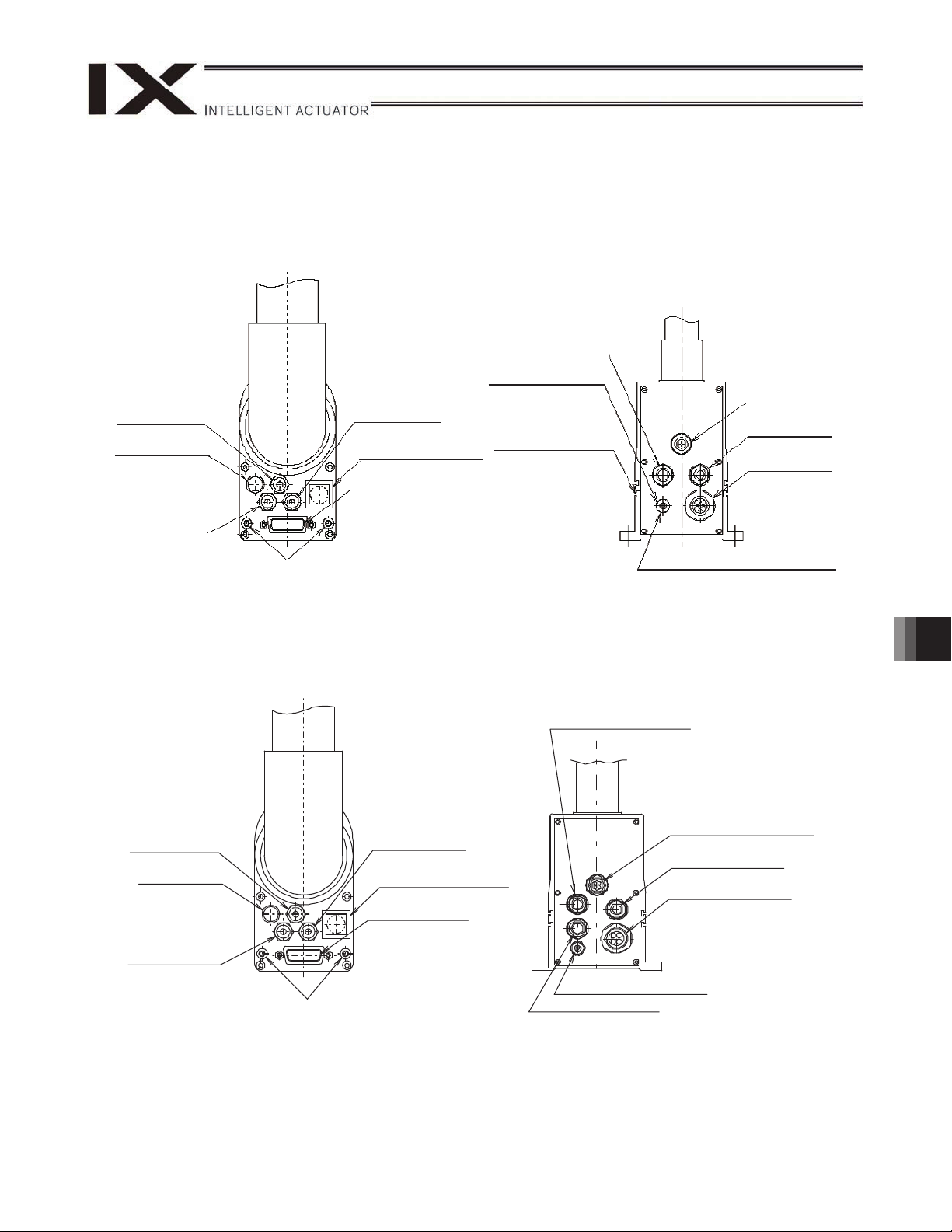
12.5 User Wiring and Piping
The robot comes with standard cables and tubes that the user can use in a desired wiring/piping configuration.
12.5.1 IX-NNN2515H/3515H, IX-NNC2515H/3515H
IX-NNN2515H/3515H
M cable
Quick joint 4
(red)
ALM (indicator)
Quick joint 4
(black)
Spacer for user part installation
IX-NNC2515H/3515H
Quick joint 4
(red)
ALM (indicator)
Brake power cable
Quick joint
(white)
BK SW
Brake-release switch
User connector
4
T-slot for peripheral
installation (M3, M4)
BK power cable (outside robot)
Panel Rear Panel
Suction pipe joint
(Applicable tube: Outer
diameter 12)
Quick joint 4
(white)
BK SW
Brake-release switch
User connector
Air tubes (4 x 3 pcs.)
U cable (outside robot)
PG cable (outside robot)
Air tubes
4 x 3 pcs.)
(
U cable
(outside robot)
PG cable
(outside robot)
12. Precautions for Use
Quick joint 4
(black)
Spacer for user part installation
Panel
BK power cable (outside robot)
M cable (outside robot)
Rear Panel
71
Page 78

User connector specifications
Rated voltage 30 V
Permissible current 1.1 A
Conductor size and number
of wires
Other
AWG 26 (0.15 mm
Twisted-pair cable (1 to 24),
shielded
2
), 15 wires
Shape of Y-terminal
Piping specifications
Normal service pressure 0.8 MPa
Dimensions (outer diameter x
inner diameter) and number
4 mm x 2.5 mm, 3 pieces
of tubes
Working medium Air
ALM (indicator) specifications
Rated voltage 24 VDC
Rated current 12 mA
Illumination color Red LED
Spacer for user part installation
7
M4, depth 5
30 N or less
m or less
2 N
External force applied to the spacers must not
exceed 30 N in the axial direction or 2 Nm in the
rotating direction (for each spacer).
12. Precautions for Use
72
Page 79

The user connector comes with the mating D-sub 25-pin plug.
The robot comes with a 15-pin plug for the D-sub connector for user wiring.
Solder a user-supplied cable to the D-sub connector (plug), attach the supplied hood, and then connect to the
user connector (socket). Use a shielded cable with an outer diameter of
11 or less.
To turn on the ALM (indicator), the user must configure a dedicated circuit that uses the controller I/O output
signal, etc.
User connector pins and corresponding Y-terminals
Inside unit Cable
Arm 2 side
Connection
D-sub,
15-pin
User Connector
ALM
Indicator
(LED)
To D-sub connector frame
No.
10
11
12
13
14
15
Y-terminal designation
1
2
3
4
5
6
7
8
9
LED +24V
LED G24V
U1
U2
U3
U4
U5
U6
U7
U8
U9
U10
U11
U12
U13
U14
U15
FG
Controller side
Wire color Connection
Orange 1 red
Orange 1 black
Light gray 1 red
Light gray 1 black
White 1 red
White 1 black
Yellow 1 red
Yellow 1 black
Pink 1 red
Pink 1 black
Orange 2 red
Orange 2 black
Lightgray 2 red
Light gray 2 black
White 2 red
White 2 black
Yellow 2 red
Green
Y-terminal
12. Precautions for Use
To base
Warning
Before commencing wiring/piping work, turn off the power to the controller and the power/air supplies to the
robot. Failure to do so may cause the robot to malfunction.
Use cables and tubes within their specifications. Failure to do so may result in fire or short circuit due to an
overheated cable, or may cause air leaks.
Connect the shielded cable to the hood. Otherwise, the robot may malfunction due to noise.
Secure the supplied D-sub connector using the screws on the hood.
73
Page 80

12.5.2 IX-NNW2515H/3515H
Air supply port for air purge
(Applicable tube: Outer diameter 6)
BK SW
Brake-release switch
ALM (indicator)
User connector
Spacer for user part installation
Panel
User connector specifications
Rated voltage 30 V
Permissible current 1.1 A
Conductor size and number
of wires
Other
AWG 26 (0.15 mm
Twisted-pair cable (1 to 14),
shielded (16)
Quick joint 4
(black)
Quick joint 4
(white)
Quick joint 4
(red)
2
), 15 wires
Air tubes (4 x 3 pcs.)
U cable (outside robot)
PG cable (outside robot)
Brake power cable (outside robot)
M cable (outside robot)
Rear Panel
Shape of Y-terminal
12. Precautions for Use
Piping specifications
Normal service pressure 0.8 MPa
Dimensions (outer diameter x
inner diameter) and number
of tubes
Working medium Air
ALM (indicator) specifications
Rated voltage 24 VDC
Rated current 12 mA
Illumination color Red LED
74
4 mm x 2.5 mm, 3 pieces
Spacer for user part installation
7
M4, depth 5
30 N or less
m or less
2 N
External force applied to the spacers must not
exceed 30 N in the axial direction or 2 Nm in the
rotating direction (for each spacer).
Page 81

The user connector comes with a mating 16-pin plug.
Connector pins 1 to 15 can be used. Pin 16 is connected to a shield wire and cannot be used as a signal wire.
Use a cable with an outer diameter of 13.1 to 15.0. The wiring method for the supplied connector is shown
below.
Clamp nut Setscrew B Washer
Cable
gasket
End bell Coupling nut Barrel
Setscrew A
[1]: Screw the barrel into the end bell and secure with setscrew A.
[2]: Push the cable gasket and washer into the end bell and screw in the clamp nut by holding the end bell in
position.
[3]: Move the cable back and forth and to the left and right to ensure smooth movement, tighten the clamp nut
again to the specified torque, and secure with screw B.
~ Tightening torque for each screw
End bell: 10 kgf-cm to 15 kgf-cm
Clamp nut: 15 kgf-cm to 20 kfg-cm
Setscrew A, B: 2 kgf-cm to 3 kgf-cm
If the waterproof user connector and user piping joint are not used, put the supplied cap and blind plug to seal
the openings, respectively. If not, water and dust will enter.
12. Precautions for Use
CautionWarning
Before commencing wiring/piping work, turn off the power to the controller and the power/air supplies to the
robot. Failure to do so may cause the robot to malfunction.
Use cables and tubes within their specifications. Failure to do so may result in fire or short circuit due to an
overheated cable, or may cause air leaks.
Connect the shielded cable to the hood. Otherwise, the robot may malfunction due to noise.
If the user connector is not used, put the cap to seal the opening. If not, water and dust will enter.
Tighten the connector to the specified torque.
If the outer diameter is smaller than the one specified for the applicable cable, use tape, etc., to adjust the
outer diameter before installing.
75
Page 82

User connector pins and corresponding Y-terminals
Inside unit Cable
Arm 2 side
Connection
Waterproof
connector,
15 pins
Y-terminal designation
Controller side
Wire color
Orange 1 red
Orange 1 black
Light gray 1 red
Light gray 1 black
White 1 red
White 1 black
Yellow 1 red
Yellow 1 black
Pink 1 red
Pink 1 black
Orange 2 red
Orange 2 black
Light gray 2 red
Light gray 2 black
White 2 red
Connection
Y-terminal
12. Precautions for Use
Warning
Before commencing wiring/piping work, turn off the power to the controller and the power/air supplies to the
robot. Failure to do so may cause the robot to malfunction.
Use cables and tubes within their specifications. Failure to do so may result in fire or short circuit due to an
overheated cable, or may cause air leaks.
Connect the shielded cable to the pin 16. Otherwise, the robot may malfunction due to noise.
Indicator
(LED)
White 2 black
Yellow 2 red
Green
To base
76
Page 83

12.6 Suction Rate of Cleanroom Specification IX-NNC2515H/3515H
Cleanness class 10 can be achieved by suctioning air at the specified rate through the quick joints for suction
provided on the base and rear panel.
The suction device and suction air tubes (12) are provided by the customer.
Suction rate (Nl/min)
80
Quick joint for suction (applicable
tube: outer diameter 12, inner
diameter 8)
12. Precautions for Use
77
Page 84

12.7 Air Purge for Dust-proof/Splash-proof Specification IX-NNW2515H/3515H
By applying the pressure specified below from the air supply port provided on the side face of the base, the robot
will conform to the IP65 dust-proof/splash-proof specification.
Service pressure Pressure in a range of 0.3 to 0.6 MPa immediately before the bellows inflates
Outer diameter x Inner diameter
Fluid used
z Flow rate adjustment method
The customer should provide a relief valve. Fully close the speed controller supplied with the actuator, set
the pressure to 0.3 MPa or more but not exceeding 0.6 MPa, and then adjust the flow rate using the speed
controller supplied with the actuator.
Supplying too much air will inflate the bellows.
Adjust the speed controller by following the procedure below.
<Increase the flow rate>
Turn the needle of the speed controller counterclockwise from the fully closed position to increase the flow
rate.
Supplying too much air will inflate the bellows, so adjust the needle until immediately before the bellows
inflates.
After the adjustment, be sure to tighten the lock nut to maintain the flow rate.
Outer diameter 6 x Inner diameter 4
Clean, dry air free from compressor oil, etc. The air filtration rating shall be
10m or less (dew point of dry air in atmosphere shall be -20C or less).
12. Precautions for Use
Caution
Be sure to use clean, dry air with an atmospheric dew point of -20C or less. If dry air is not used,
condensation may occur inside the robot, resulting in earth leakage or malfunction.
Do not apply pressure exceeding the specified maximum pressure of 0.6 MPa. Doing so may cause the
seals to break and impair the robot’s dust-proof/drip-proof performance.
Adjust the pressure and also adjust the flow rate using the speed controller at the back of the base to
prevent intrusion of powder dust.
Lock nut
Needle
78
Page 85

13. Inspection/Maintenance
13.1 Inspection/Maintenance
Your horizontal articulated robot must be inspected daily and on a regular basis to ensure safe, efficient
operation. Perform the necessary inspections after confirming the maintenance/inspection items required for
your IAI robot, as defined in this section.
Do not inspect, adjust or repair the robot or controller, replace any of the robot/controller parts, or perform any
other operation in a manner not specified in this operation manual. In particular, do not disassemble the robot or
controller or cut any robot/controller cable in the installation location because it will necessitate adjustments
using factory machines.
Disassembly of servo motor
Disassembly of ball reduction gear
Disassembly of ball-screw spline
Disassembly of bearing
Disassembly of harmonic speed reducer
Disassembly of brake
Cutting of cable
IAI may not be able to repair any malfunction or failure occurring as a result of or in connection with the
performance of any of the operations listed above.
Periodic inspection covers items that must be performed with or without the controller power turned on. In either
case, take proper measures so that operators other than the person carrying out the inspection will not be able
to accidentally operate the power switch.
Warning
z Performing inspection or maintenance without fully understanding the details of work may result in a
serious accident.
z If inspections are neglected, the drive part may wear prematurely or the robot may malfunction
unexpectedly.
13. Inspection/Maintenance
79
Page 86

13.1.1 Daily Inspection
Check the following items daily before and after operating the robot.
Observe the precautions for work near the robot and for inspection/maintenance/adjustment operations when
carrying out each check.
noitpircseDnoitacolkcehC
Safety cage
Robot
Cables
Emergency-stop switch
• Correct the deformation or positional shift of the cage.
• Confirm that the interlock mechanism is operating properly.
• Check the robot mounting bolts for looseness.
• Check the exterior for abnormality, loose covers, flaws, dents, etc.
(If the robot has flaws or other abnormalities, please contact IAI.)
• Check for abnormal move, vibration or noise.
• Check the cables for flaws.
• Check the cable mounting parts for looseness.
• Confirm that the emergency-stop switch functions properly.
13.1.2 Six-Month Inspection
Check the following items on the robot every six months.
Observe the precautions for work near the robot and for inspection/maintenance/adjustment operations when
carrying out each check.
noitpircseDnoitacolkcehC
Robot Check the arm mounting sections for looseness.
(If any of the arm mounting sections is loose, tighten the fastening parts securely.)
Ball-screw spline
Connectors Check the connectors for looseness.
If the robot has flaws or other abnormalities, please contact IAI.
• Check the ball screw and ball spline for looseness.
• Add grease after removing old grease with a waste cloth, etc.
(Standard type: Multitemp LRL 3 Grease (Manufacted by Kyodo Yushi) or
equivalent
Dust proof/Splash proof type, Cleanroom type: AFE grease (Manufacted by THK)
or equivalent)
Caution
••In case the grease got into your eye, immediately go to see the doctor to get an appropriate care.
After finishing the grease supply work, wash your hands carefully with water and soap to rinse the
13. Inspection/Maintenance
grease OFF.
80
Page 87

13.1.3 Yearly Inspection
Check the following items on the robot every year.
Observe the precautions for work near the robot and for inspection/maintenance/adjustment operations when
carrying out each check.
noitpircseDnoitacolkcehC
Joint bearing for
harmonic reduction gear
Ball-screw spline Check the vertical axis for looseness. (Contact IAI if an abnormality is found.)
Check arms 1 and 2 for looseness in the rotating direction and axial direction.
(Contact IAI should you find any abnormality.)
Warning
• Performing inspection or maintenance without fully understanding the details of work may result in a
serious accident.
• If inspections are neglected, the drive part may wear prematurely or the robot may malfunction
unexpectedly.
• Display a “Work in Progress” sign so that other operators will not operate the controller, operation panel,
etc.
13.2 Battery Replacement
13.2.1 Preparation
The following items are required when replacing the batteries:
Before replacing the batteries, turn off the power to the controller, control panel and other relevant units.
IX-NNN2515H/3515H
IX-NNW2515H/3515H
IX-NNC2515H/3515H
Allen wrench AB3 (4 pcs)
13. Inspection/Maintenance
noitacificepsylno-x1,weNlooTrebmunledoM
81
Page 88

13.2.2 Replacement Procedure IX-NNN2515H/3515H, IX-NNC2515H/3515H
(1) Remove the six low-head cap screws (6 pcs) and remove the rear panel (base).
(2) Remove the batteries from the battery holder.
(3) Remove the batteries from the extension cables from the battery connectors, and connect new batteries.
After removing the old batteries, quickly connect new batteries (roughly within 5 minutes x
number of batteries).
If new batteries are not connected for a longer period, the rotation data will be lost and an
absolute reset will become necessary.
Replace batteries one axis at a time. If the batteries for all axes are replaced at once, the work
may not be completed within the specified time.
(4) Install the batteries into the battery holder.
Battery connector 1
(for axis 1)
Battery (for axis 1)
Battery connector 3
(for axis 3)
Battery
(for axis 3)
Battery connector 2
(for axis 2)
Battery (for axis 2)
Battery connector 4
(for axis 4)
Battery (for axis 4)
[1] 6 - M4 x 8
(low-head cap screw)
Rear panel
(base)
13. Inspection/Maintenance
(5) Affix the rear panel (base) using the six low-head cap screws [1].
Caution
When installing the rear panel (base), be careful not to pinch the cables inside.
Be careful not to leave out the seal washer.
82
Page 89

12.2.3 Replacement Procedure IX-NNW2515H/3515H
(1) Remove the six low-head cap screws (6 pcs) and remove the rear panel (base).
(2) Remove the batteries from the battery holder.
(3) Remove the batteries from the extension cables from the battery connectors, and connect new batteries.
After removing the old batteries, quickly connect new batteries (roughly within 5 minutes x
number of batteries).
If new batteries are not connected for a longer period, the rotation data will be lost and an
absolute reset will become necessary.
Replace batteries one axis at a time. If the batteries for all axes are replaced at once, the work
may not be completed within the specified time.
(4) Install the batteries into the battery holder.
Battery connector 1
(for axis 1)
Battery connector 2
(for axis 2)
Battery (for axis 1)
Battery
(for axis 3)
Battery connector 3
(for axis 3)
[1] 6-M4 X 8
(low-head cap screw)
Battery (for axis 2)
Battery (for axis 4)
Battery connector 4
(for axis 4)
13. Inspection/Maintenance
Rear panel
(base)
(5) Affix the rear panel (base) using the six low-head cap screws [1].
Caution
When installing the rear panel (base), be careful not to pinch the cables inside.
Remember to insert the seal washer.
83
Page 90

13.3 Absolute Encoder Reset Method
13.3.1 Preparation for Absolute Reset
The following jigs are required to perform an absolute reset.
Absolute reset adjustment jigs
Model
number
JG-2 For arm length 250/300/350
Connect the robot, controller and PC cables so that the robot/controller can be operated using the PC software.
Be sure to check the EMG switch operation beforehand.
An absolute reset of the rotational and vertical axes requires absolute reset adjustment jigs, but jigs are not
always required for an absolute reset of arms 1 and 2.
(A multi-rotation reset can be performed as long as the current position is within 1 graduation on the positioning
mark sticker.)
Remarks
Plate
Pin
Warning
Fully understand the applicable inspection/maintenance work, because failure to do so may result in a
serious injury accident.
Put up a “WORK IN PROGRESS” sign to prevent other operators from accidentally operating the
13. Inspection/Maintenance
controller, operation panel, etc. Remember to insert the seal washer
84
Example of Absolute Reset Adjustment Jig(Model number JG-2)
Page 91

13.3.2 Starting the Absolute Reset Menu
A
(1) Open the Abs Encoder Reset window from the PC software.
(*) Select “Absolute Reset (SCARA Axis) (Y)" if you are using an X-SEL-PX/QX controller.
Starting Up Absolute Reset Window
2. The Abs Encoder Reset window opens.
One of three absolute reset screens for arm 1, arm 2 and rotational axis + vertical axis is displayed
when a corresponding tab is clicked.
Abs Encoder Reset
screen for arm 1 or 2
bs Encoder Reset
screen for rotational
axis + vertical axis
13. Inspection/Maintenance
Absolute Reset Window
85
Page 92

13.3.3 Absolute Reset Procedure for Arm 1 or 2
(1) Click the “Encoder Rotation Data Reset1” button.
(2) Click the “Reset Controller Error” button.
13. Inspection/Maintenance
86
Encoder Multi-rotation Data Reset 1
Controller Reset
Page 93

(3) Click the “Servo ON” button.
Servo ON
(4) Jog the arm to near the reference position (see reference position drawing in step (7), and click the “Jog
end” button.
(5) Click the “Servo-OFF” button.
13. Inspection/Maintenance
Jogging
Servo OFF
87
Page 94

(6) Press the emergency-stop switch.
(7) When performing an absolute reset of arm 1, set the adjustment jig (pin) on arm 1 to secure the arm in its
reference position. You can move arm 2 when securing arm 1. When performing an absolute reset of arm 2,
set the adjustment jig (pin) on arm 2 to secure the arm in its reference position. You can move arm 1 when
securing arm 2.
Set the jig after confirming that the emergency-stop switch is pressed.
Set the jig after adjusting the arm to the reference position, using the positioning mark label as a guide.
Arm 1 has a cover, which is fixed with setscrews. Remove the setscrews and detach the cover before
setting the jig.
It is recommended that an adjustment jig be used to perform an absolute reset. With arm 1 or 2,
however, rotation data can be reset as long as a positioning precision of “center of positioning mark label
1 graduation” is ensured.
13. Inspection/Maintenance
88
Page 95

Positioning mark
Arm 1
(arm length 250/350)
label for arm 1
Insertion depth: Approx. 60 mm
Positioning mark
label for arm 2
Insertion depth: Approx. 20 mm
Reference Posture for Arm Length 250/350
Arm 2
(arm length 250/350)
(Note) For an absolute reset of arm 1 of the IX-NNN2515, slightly bend arm 2 and set the adjustment jig (pin).
13. Inspection/Maintenance
Warning
Always press the emergency-stop switch before setting an adjustment jig. Failure to do so may cause the
robot to malfunction and result in a serious accident.
89
Page 96

(8) Click the “OK” button.
Confirmation
(9) Click the “Encoder Rotation Data Reset2” button.
13. Inspection/Maintenance
90
Encoder Multi-rotation Data Reset 2
Page 97

(10) Remove the adjustment jig.
If you are working on arm 1, install the cover and secure it with the setscrews.
(11) Release the emergency-stop switch.
(12) Click the “OK” button.
An arrow is shown next to the “Home pos. automatic update” button. Do not set this item. (In particular, be
sure this item is not set when performing an absolute reset without using a jig).
If you have allowed the home preset value to be updated automatically by mistake, do not write the updated
data to the flash ROM. Instead, perform a software reset. (After the software reset, the data will return to the
original condition before the home preset value was automatically updated.)
Always click the “OK” button after removing the jig and releasing the emergency-stop switch.
Confirmation
(13) Click “X” in the top right-hand corner to exit the absolute reset window.
Once the absolute reset is complete, be sure to reset the software.
Warning
Be careful not to perform a reset using an incorrect sequence, since it may cause the arm position to
become offset.
Update the home preset value only if any of the mechanical settings has been changed, such as after an
arm has been replaced. (Changes relating to joints only)
13. Inspection/Maintenance
91
Page 98

13.3.4 Absolute Reset Procedure for the Rotational Axis + Vertical Axis
(1) Click “Encoder Rotation Data Reset1” button.
(2) Click the “Reset Controller Error” button.
13. Inspection/Maintenance
92
Encoder Multi-rotation Data Reset 1
Controller Reset
Page 99

(3) Click the “Servo ON” button.
Servo ON
(4) Click the “Temp. Standard posture standby” button.
The vertical axis returns to its home position. Exercise caution so as not to be injured by the axis during
movement.
Standing By at Tentative Home Position
(5) Jog the rotational axis to the reference position (see reference position drawing in step 8), and click the “Jog
end” button.
Jogging
13. Inspection/Maintenance
93
Page 100

(6) Click the “Servo-OFF” button.
Servo OFF
(7) Press the emergency-stop switch.
(8) Affix the rotational axis at the reference position by setting the plate and pin of the adjustment jig as
illustrated below.
Set the jig after confirming that the emergency-stop switch is pressed.
Set the jigs by using the positioning mark as a reference.
Make sure the top surface of the stopper roughly matches in height with the bottom surface of arm 2.
13. Inspection/Maintenance
94
 Loading...