

Page 1

A
A
A
A
CatalogNo.ME0193-2A
IA Kit IK Series Assembly Procedures Edition 2
Thank you for purchasing an IAI product.
Use this Assembly Procedures as reference to assemble
your product correctly.
ROBO Cylinder Combinations
XY base fixed type
[Model]
xis configuration RCS2
xis configuration RCP2
[1] Configuration type
[2] Combination direction
Symbol X-axis (axis 1) Y-axis (axis 2)
A1 SS8R (150W) SS8R (100W)
A2 SS8C (150W) SS8C (100W)
B1 SS8R (150W) SA7R
B2 SS8C (150W) SA7R
C1 SS7R SA6R
C2 SS7C SA6R
D1 SS7R SA5R
D2 SS7C SA5R
* If the X-axis is reversed, only 1 and 2 are applicable.
Symbol
Shape
[4] Slider type
[3] Speed type
[2] Combination direction
[1] Configuration type
[3] Speed type [4] Slider type
Symbol Type
HH High speed High speed
HM High speed Medium speed
HL High speed Low speed
MM Medium speed Medium speed
Symbol Type
S Single
D Double
No. Type DWG No.
1
2
3
4
5
6
7
8
[IA kit components]
* Single slider type
For A1, A2, B1
and B2
[5] Cable bearer 1
For RCP2 actuators
C1, C2, D1 and D2
[1] XY bracket
[6] Bearer
mounting bracket 1
* Double slider type
For A1, A2, B1
and B2
[5] Cable bearer 1
[Assembly procedure]
* Single slider type
* Double slider type
For RCP2 actuators
C1, C2, D1 and D2
[1] XY bracket
[6] Bearer
mounting bracket 1
DWG No.: GMM07-053E
DWG No.: GMM07-054E
List of Drawings Referenced in Assembly Procedures
XY base fixed type Single slider type GMM07-053E
XY base fixed type
Upright type Single slider type GMM07-055E
Upright type
Crossed-type base fixed Single slider type GMM07-057E
XYB + Z base fixed type Single slider type GMM07-058E
XYB + Z base fixed type
Cable affixing method
For RCS 2
actuators C1, C2,
D1 and D2
[7] Guide rail Y
For RCS 2
actuators C1, C2,
D1 and D2
[7] Guide rail Y
Double slider type
Double slider type
Double slider type
[2] Plate X
[8] Cable bearer 2
[2] Plate X
[8] Cable bearer 2
GMM07-054E
GMM07-056E
GMM07-059E
GMM07-060E
[3] Guide rail X [4] Fra me co ve r X
[3] Guide rail X [4] Frame co ve r X
Upright type
[Model]
[1] Configuration type
Symbol X-axis (axis 1)Y-axis (axis 2)
B1 SS8R (150W) SA7R
[2] Combination direction
Symbol
Shape
[3] Speed type [4] Slider type
Symbol Type
HH High speed High speed
HM High speed Medium speed
HL High speed Low speed
MM Medium speed Medium speed
[IA kit components]
* Single slider type
[1] XZ bracket
* Double slider type
[1] XZ bracket
[Assembly procedure]
* Single slider type
DWG No.: GMM07-055E
* Double slider type
DWG No.: GMM07-056E
xis configuration RCS2
xis configuration RCP2
[4] Slider type
[3] Speed type
[2] Combination direction
[1] Configuration type
Symbol Type
S Single
D Double
[2] Cable bearer
[2] Cable bearer
[3] Bearer
mounting bracket
[3] Bearer
mounting bracket
Page 2

A
A
g
A
A
Crossed-type base fixed
[Model]
xis configuration RCS2
xis configuration RCP2
[4] Slider type
[3] Speed type
[2] Combination direction
[1] Configuration type
[1] Configuration type
[2] Combination direction
Symbol
Shape
Symbol X-axis (axis 1) Y-axis (axis 2)
B1 SS8R (150W) SA7R
[3] Speed type [4] Slider type
Symbol Type
HH High speed High speed
HM High speed Medium speed
HL High speed Low speed
MM Medium speed Medium speed
[IA kit components]
* Single slider type
[1] Plate YZ
[2] Guide rail Y [3] Frame cover Y
[4] Cable bearer 1
[7] Bearer mounting
bracket 2
[Assembly procedure]
* Single slider type
DWG No.: GMM07-057E
Symbol Type
S Single
[5] Bearer
mountin
bracket 1
[6] Cable bearer 2
XYB + Z base fixed type
[IA kit componen ts]
* Single slider type
[Model]
xis configuration RCS2
xis configuration RCP2
[4] Slider type
[3] Speed type
[2] Combination direction
[1] Configuration type
[1] Configuration type G1
Y-axis
Symbol X-axis (axis 1)
G1 SS8R (100W) SA7R SA6R
[2] Combination direction
* If the X-axis is reversed, only 1 and 2 are applicable.
Symbol
Shape
(axis 2)
Z-axis
(axis 3)
[3] Speed type [4] Slider type
Symbol Type
HHH High speed High speed High speed
HHM High speed
HHL High speed
High speed
High speed
Medium speed
Low speed
[7] Cable bearer 1
[7] Cable bearer 1
Symbol Type
S Single
D Double
[1] XY bracket
[2] Plate X [3] Plate YZ1 [6] Frame cover X [4] Plate YZ2 [5] Guide rail X
[8] Bearer
mounting bracket 1
* Double slider type
[1] XY bracket
[2] Plate X [3] Plate YZ1 [6] Frame cover X [4] Plate YZ2 [5] Guide rail X
[8] Bearer
mounting bracket 1
[Assembly procedure]
* Single slider type
DWG No.: GMM07-058E
* Double slider type
DWG No.: GMM07-059E
[9] Guide rail Y
[9] Guide rail Y
[10] Cable bearer 2
[10] Cable bearer 2
[11] Bearer mounting
bracket 2
[11] Bearer
mounting bracket 2
Page 3

j
j
(P)
A
A
g
Note: z Although the corners of each part have been chamfered, exercise due caution during
assembly to prevent injury. If necessary, wear gloves and other protective gears.
z Exercise due caution durin
[Tools] Allen wrench, spanner wrench, ruler
1
Parallel pin (1 pc or 2 pcs)
Screw lock holes
Model Parallel pin Hex head bolt Tightening torque
Note: To ensure squareness of the X-axis and Y-axis, place one parallel pin.
After ad
usting the squareness of the X-axis and Y-axis, affix the hex head bolt.
Parallel pin holes
∅8h7 x 25
∅5h7 x 25
4
Hex socket-head bolt (2 pcs)
Hex nut (2 pcs)
Y-axis
[1] XY bracket
Set the dimension from the side face
of the XY bracket to the tip of bearer
mounting bracket 1 [6] to 152.5 mm.
* This assembly procedure applies to combination direction 1. With other combination directions such as 2 and 3 , the actua tor and bracket directions are dif ferent. If y ou are using co mbination direction 2 or 3, assemble the p art s by
referring to this drawing.
Model
Hex socket-head bolt
assembly to prevent pinching of your hands and fingers.
2
Hex head bolt + plain washer (4 pcs)
[1] XY bracket
[2] Plate X
Hex socket-head bolt (4 pcs)
X-axis
Screw lock holes
Insert a washer
in the case of
S
M8 x 30 mm
M5 x 25 mm
Note: To ensure squareness of the X-axis and Y-axis, place one parallel pin.
5
[6] Bearer mounting bracket 1
X-axis
[3] Guide rail X
[6] Bearer
mounting
bracket 1
Set the dimension from the side face
of the XY bracket to the tip of bearer
mounting bracket 1 [6] to 172.5 mm.
M4 x 8 mm
Tightening torque
Y-axis
Parallel pin (1 pc or 2 pcs)
SXBA.
Model Parallel pin
After ad
Hex socket-head countersunk (4 pcs)
Y-axis
X-axis
Model
∅5h7 x 12
∅4h7 x 10
∅4h7 x 10
∅4h7 x 10
usting the squareness of the X-axis and Y-axis, affix the hex head bolt.
[1] XY bracket
Hex socket-head bolt
M8 x 18 mm
M5 x 15 mm
M5 x 12 mm
M5 x 12 mm
[5] Cable bearer 1
[3] Guide rail X
Hex socket-head
countersunk
M3 x 6 mm
[2] Plate X
Hex socket-head countersunk (4 pcs)
With combination directions 2
through 4, the actuator and
bracket directions are different.
X-axis
Tightening torque
Hex nut (4 pcs)
Align the end face of cable
bearer 1 [5] with the end
face of guide rail X [3].
Tightening torque
3
6
XY base fixed type: Single slider type
IK2-S(P)XBS
DWG. No. GMM07-053E 1/2
The following procedures apply to configurations with a cable bearer.
Install the X-axis and guide rail X.
X-axis
[3] Guide rail X
X-axis
[3] Guide rail X
Y-axis
Model
Bottom view
Bottom view
T-slot in XY bracket [1]
[7] Guide rail Y
Hex socket-head bolt
M4 x 8 mm
lign the end face of
the base with the end
face of guide r ail X.
lign the end face of
the base with the end
face of guide rail X.
Align the end face position of
guide rail Y [7] with the end face
position of the XY bra c k et [1] .
Hex socket-head bolt (3 pcs)
Hex nut (3 pcs)
X-axis
Tightening torque
Page 4

(
(Note) One side of cable bearer 2 [8] is free. The customer should
7
install cable bearer 2 when installing a handle, etc.
Y-axis
[7] Guide rail Y
Hex socket-head countersunk (4 pcs)
Hex nut (4 pcs)
Model
[7] Guide rail Y
Installation position of IK2-S(P) SXBA (SXBB) S
Y-axis str o k e
50 mm 81.5
100 mm 106.5
150 mm 131.5
200 mm 156.5
250 mm 181.5
300 mm 206.5
350 mm 231.5
400 mm 256.5
Installation position of IK2-S(P) SXBC (SXBD) S
Y-axis str o k e
50 mm 80.0
100 mm 105.0
150 mm 130.0
200 mm 155.0
250 mm 180.0
300 mm 205.0
350 mm 230.0
400 mm 255.0
[8] Cable bearer 2
Hex socket-head
countersunk
M3 x 6 mm
Installation position of cable bearer 2 [8]
Y-axis
See the table below.
Length from end face of guide rail Y
(front side) to fixed end of bearer
Length from end face of guide rail Y
(front side) to fixed end of bearer
Tightening torque
[8] Cable bearer 2
XY base fixed type: Single slider type
IK2-S(P)XBS
DWG. No. GMM07-053E 2/2
Arrange the wires so that each axis will not contact the cables and
8
connectors when the axis is moved over its entire stroke.
(Note) If you want to move the actuator with brake by hand, connect the
controller and supply the power and then set the brake release switch to
RLS) side.
the release
Y-axis
Cables from hand, etc.
[8] Cable bearer 2
Connect the motor
cable/encoder
cable connectors.
Guide rail
* Refer to “Cable affixing method: GMM07-060” for affixing of cables.
X-axis
Frame cover
[5] Cable bearer 1
Page 5

g
j
p
∅
A
A
j
(P)
Note: z Although the corners of each part have been chamfered, exercise due caution during
assembly to prevent injury. If necessary, wear gloves and other protective gears.
z Exercise due caution durin
[Tools] Allen wrench, spanner wrench, ruler
1
Hex socket-head bolt +
lain washer (8 pcs)
Parallel pin (2 pcs)
Screw lock holes
Screw lock holes
Combination directions 1, 3
Model Parallel pin Hex s ocket-head bolt Tightening torque
Screw lock holes
Parallel
pin holes
Screw lock
holes
∅8h7 x 18
∅5h7 x 14
4
The following procedures apply to configurations with a cable bearer.
Install the X-axis and guide rail X.
X-axis
[3] Guide rail X
Bottom view
assembly to prevent pinching of your hands and fingers.
2
Hex head bolt +
high-tension washer (6 pcs)
[2] Plate X
Parallel pin (1 pc or 2 pcs)
X-axis
Screw lock holes
Parallel
pin holes
Screw lock
holes
Combination directions 2, 4
Screw lock holes
Screw lock holes
M8 x 20 mm
M5 x 20 mm
Note: To ensure squareness of the X-axis and Y-axis, place one parallel pin.
5
Hex socket-head bolt (2 pcs)
Hex nut (2 pcs)
lign the end face of
the base with the end
face of guide rail X.
[1] XY bracket
X-axis
[3] Guide rail X
Bottom view
lign the end face of
the base with the end
face of guide rail X.
Set the dimension from the side face
of the XY bracket to the tip of bearer
mounting bracket 1 [6] to 152.5 mm.
With combination direct ions 2 and 3,
the bracket direction is diff er ent.
[1] XY bracket
[2] Plate X
Screw lock holes: ∅9
Screw lock holes:
Model Parallel pin Hex head bolt Tightening torque
After ad
usting the squareness of the X-axis and Y-axis, affix the hex head bolt.
Y-axis
Model Hex socket-head bolt Tightening torque
9
∅8h7 x 18
∅5h7 x 14
M8 x 20 mm
M5 x 18 mm
M4 x 8 mm
X-axis
Parallel pin hol es : ∅8
Screw lock holes: ∅9
[6] Bearer mounting bracket 1
Set the dimension from the side face
of the XY bracket to the tip of bearer
mounting bracket 1 [6] to 172.5 mm.
X-axis
[3] Guide rail X
3
Hex socket-head bolt (4 pcs)
Insert a washer
in the case of
SXBA.
S
Note: To ensure squareness of the X-axis and Y-axis, place one parallel pin.
6
Hex socket-head countersunk (4 pcs)
[6] Bearer
mounting
bracket 1
X-axis
XY base fixed type: Double slider type
IK2-S(P)XBD
DWG. No. GMM07-054E 1/2
With combination directions 2 through 4,
Y-axis
Parallel pin ( 1 pc or 2 pcs)
Model Parallel pin Hex soc ket-head bolt Tightening torque
usting the squareness of the X-axis and Y-axis, affix the hex head bolt.
After ad
Y-axis
Model
∅5h7 x 12
∅4h7 x 10
∅4h7 x 10
∅4h7 x 10
Hex socket-head
countersunk
the actuator direction is different.
X-axis
[1] XY bracket
[2] Plate X
M8 x 18 mm
M5 x 15 mm
M5 x 12 mm
M4 x 12 mm
Hex socket-head countersunk (4 pcs)
[5] Cable bearer 1
[3] Guide rail X
M3 x 6 mm
Hex nut (4 pcs)
Align the end face of cable
bearer 1 [5] with the end
face of guide rail X [3].
Tightening torque
* This assembly procedure applies to combination direction 1. With other combination directions such as 2 and 3 , the actua tor and bracket directions are dif ferent. If y ou are using co mbination direction 2 or 3, assemble the p art s by
referring to this drawing.
Page 6

(
XY base fixed type: Double slider type
IK2-S(P)XBD
DWG. No. GMM07-054E 2/2
7
T-slot in XY bracket [1]
Align the end face position of
guide rail Y [7] with the end face
position of the XY bracket [1].
Y-axis
[7] Guide rail Y
Hex socket-head bolt (3 pcs)
X-axis
Hex nut (3 pcs)
Model Hex socket-head bolt Tightening torque
M4 x 8 mm
8
(Note) One side of cable bearer 2 [8] is free. The customer should
install cable bearer 2 when installing a handle, etc.
Y-axis
[8] Cable bearer 2
[7] Guide rail Y
Hex socket-head countersunk (4 pcs)
Hex nut (4 pcs)
Model
Installation position of cable bearer 2 [8]
Y-axis
Hex socket-head
countersunk
M3 x 6 mm
Tightening torque
[8] Cable bearer 2
[7] Guide rail Y
See the table below.
Installation position of IK2-S(P) SXBA (SXBB) D
Y-axis str o k e
100 mm 106.5
150 mm 131.5
200 mm 156.5
250 mm 181.5
300 mm 206.5
350 mm 231.5
400 mm 256.5
Installation position of IK2-S(P) SXBC (SXBD) D
Y-axis str o k e
100 mm 105.0
150 mm 130.0
200 mm 155.0
250 mm 180.0
300 mm 205.0
350 mm 230.0
400 mm 255.0
Length from end face of guide rail Y
50 mm 81.5
50 mm 80.0
(front side) to fixed end of bearer
Length from end face of guide rail Y
(front side) to fixed end of bearer
Arrange the wires so that each axis will not contact the cables and
9
connectors when the axis is moved over its entire stroke.
(Note) If you want to move the actuator with brake by hand, connect the
controller and supply the power and then set the brake release switch to
RLS) side.
the release
Y-axis
Cables from hand, etc.
X-axis
[8] Cable bearer 2
Connect the motor
cable/encoder
cable connectors.
[5] Cable bearer 1
Guide rail
Frame cov er
* Refer to “Cable affixing method: GMM07-060” for affixing of cables.
Page 7

(
g
Note: z Although the corners of each part have been chamfered, exercise due caution during
assembly to prevent injury. If necessary, wear gloves and other protective gears.
z Exercise due caution durin
[Tools] Allen wrench, spanner wrench, ruler
1
Parallel pin
( 2 pcs)
Model Parallel pin Hex head bolt Tightening torque
(Note) One side of the cable bearer is free. The customer should install the cable
4
∅8h7 x 18
bearer as necessary.
[1] XZ bracket
[Installation of cable bearer [2] on bearer mounting bracket [3]]
Model
* This assembly procedure applies to combination direction 1. With other combination directions such as 2 and 3 , the actua tor and bracket directions are dif ferent. If y ou are using co mbination direction 2 or 3, assemble the p art s by
referring to this drawing.
Hex socket-head
countersunk
M3 x 6 mm
assembly to prevent pinching of your hands and fingers.
With combination direct ions 2 through
4, the bracket direction is different.
Hex head bolt + plain washer
(4 pcs)
[1] XZ bracket
X-axis
M8 x 20 mm
Z-axis
Hex socket-head countersunk (4 pcs)
[2] Cable bearer
X-axis
Tightening torque
2
With combination directions 2 through
4, the actuator direction is different.
Parallel pin ( 2 pcs)
Hex socket-head bolt (4 pcs)
Model Parallel pin
5
Arrange the wires so that each axis will not contact the cables and
connectors when the axis is moved over its entire stroke.
(Note) If you want to move the actuator with brake by hand, connect the
* Refer to “Cable affixin g me th od : GM M0 7- 060 ” f or affix i ng of ca bl es .
∅4h7 x 10
controller and supply the power and then set the brake release switch to
the release
RLS) side.
Z-axis
[1] XZ brac ket
Hex socket-head
bolt
M5 x 12 mm
X-axis
Tightening torque
3
Hex socket-head bolt (2 pcs)
Upright type: Single slider type
IK2-S(P)XZS
DWG. No. GMM07-055E 1/1
The following procedures apply to configurations with a cable bearer.
[1] XZ bracket
[3] Bearer mounting bracket
[Installation of bearer mounting bracket [3] on XZ bracket [1]]
Model Hex socket-head bolt Tightening torque
With combination directions 2 through 4, the installation direction of
the bearer mounting bracket [3] is differ ent.
[3] Bearer
mounting
bracket
[3] Bearer
mounting
bracket
M6 x 10 mm
Z-axis
[3] Bearer
mounting
bracket
X-axis
Page 8

(
r
Note: z Although the corners of each part have been chamfered, exercise due caution during
assembly to prevent injury. If necessary, wear gloves and other protective gears.
z Exe
[Tools] Allen wrench, spanner wrench, ruler
1
Parallel pin(2 pcs)
4
* This assembly procedure applies to combination direction 1. With other combination directions such as 2 and 3 , the actua tor and bracket directions are dif ferent. If y ou are using co mbination direction 2 or 3, assemble the p art s by
referring to this drawing.
cise due caution during assembly to prevent pinching of your hands and fingers.
With combination directions 2 through
4, the bracket direction is different.
Hex head bolt + plain
washer (4 pcs)
[1] XZ bracket
X-axis
Model Parallel pin Hex head bolt Tightening torque
∅8h7 x 18
M8 x 20 mm
(Note) One side of the cable bearer is free. The customer should install the cable
bearer as necessary.
Z-axis
Hex socket-head countersunk (4 pcs)
[2] Cable bearer
[1] XZ bracket
X-axis
[Installation of cable bearer [2] on bearer mounting bracket [3]]
Model
Hex socket-head
countersunk
M3 x 6 mm
Tightening torque
2
With combination directions 2 through
4, the actuator direction is different.
Parallel pin (2 pcs)
Hex socket-head bolt (4 pcs)
Model Parallel pin
5
Arrange the wires so that each axis will not contact the cables and
connectors when the axis is moved over its entire stroke.
(Note) If you want to move the actuator with brake by hand, connect the
* Refer to “Cable affixing method: GMM07-060” for affixing of cables.
∅4h7 x 10
controller and supply the power and then set the brake release switch to
the release
RLS) side.
Z-axis
[1] XZ bracket
Hex socket-head
bolt
M5 x 12 mm
X-axis
Tightening torque
3
Hex socket-head bolt (2 pcs)
Upright type: Double slider type
IK2-S(P)XZD
DWG. No. GMM07-056E 1/1
The following procedures apply to configurations with a cable bearer.
[1] XZ bracket
[3] Bearer moun ting bracket
[Installation of be arer mounti ng bracket [ 3 ] on XZ bracket [1]]
Model Hex socket-head bolt Tightening torque
With combination directions 2 through 4, the installation direction of
the bearer mounting bracket [3] is different.
[3] Bearer
mounting
bracket
[3] Bearer
mounting
bracket
M6 x 10 mm
Z-axis
[3] Bearer
mounting
bracket
X-axis
Page 9

p
A
g
Note: z Although the corners of each part have been chamfered, exercise due caution during
assembly to prevent injury. If necessary, wear gloves and other protective gears.
z Exercise due caution durin
1
[Tools] Allen wrench, spanner wrench, ruler
Hex socket-head bolt +
lain washer (4 pcs)
[1] Plate YZ
Model Parallel pin
∅8h7 x 18
assembly to prevent pinching of your hands and fingers.
2
Y-axis
Parallel pin ( 2 pcs)
Hex socket-head
bolt
M8 x 15 mm
Tightening torque
Model Parallel pin
With combination direction 2, the actuator direction is different.
Z-axis
Parallel pin (1 pc)
[1] Plate YZ
Y-axis
Hex socket-head bolt (4 pcs)
∅4h7 x 10
Hex socket-head
bolt
M5 x 18 mm
Tightening torque
3
Crossed-type base fixed: Single slider type
IK2-S(P)YBS
DWG. No. GMM07-057E 1/2
The following procedures apply to configurations with a cable bearer.
Install the Y-axis and guide rail Y.
lign the end face of
the base with the end
[2] Guide rail Y
Y-axis
face of the guide rail.
4
Z-axis
[1] Plate YZ
[5] Bearer mounting bracket 1
[2] Guide rail Y
Y-axis
Hex socket-head bolt (2 pcs)
Model Hex socket-head bolt Tightening torque
* This assembly procedure applies to combination direction 1. With other combination directions such as 2, the actuator and bracket directions are different. If you are using combination direction 2 or 3, assemble the parts by
referring to this drawing.
M5 x 18 mm
5
Hex socket-head countersunk
(4 pcs)
Hex nut (4 pcs)
Align the end face of cable
bearer 1 [4] with the end
face of guide rail Y [2].
[4] Cable bearer 1
[5] Bearer mounting bracket 1
[Installation of cable bearer 1 [4] on bearer mounting bracket 1 [5]]
Model
Model
Hex socket-head
countersunk (4 pcs)
[1] Plate YZ
[2] Guide rail Y
[Installation of cable bearer 1 [4] on gui de rai l 2 [2] ]
Y-axis
Hex socket-head
countersunk
M3 x 6 mm
Hex socket-head
countersunk
M3 x 6 mm
Tightening torque
Tightening torque
Z-axis
(Note) One side of cable bearer 2 is free. The customer should install cable
6
Hex socket-head
countersunk (4 pcs)
[6] Cable bearer 2
[4] Cable bearer 1
bearer 2 as necessary.
[1] Plate YZ
[Installation of bearer mounting bracket 2 [7] on pl ate YZ [1]]
Model Hex socket-head bolt Tightening torque
[Installation of cable bearer 2 [6] on bearer mounting bracket 2 [7]]
Model
M5 x 15 mm
Hex socket-head
countersunk
M3 x 6 mm
Z-axis
[7] Bearer mounting bracket 2
Hex socket-head bolt (2 pcs)
Y-axis
[2] Guide rail Y
Tightening torque
Page 10

(
(
Crossed-type base fixed: Single slider type
IK2-S(P)YBS
DWG. No. GMM07-057E 2/2
Arrange the wires so that each axis will not contact the cables and
7
connectors when the axis is moved over its entire stroke.
(Note) If you want to move the actuator with brake by hand, connect the
controller and supply the power and then set the brake release switch to
RLS) side.
the release
Y-axis (axis 1): With cable bearer / Z-axis (axis 2): Without cable bearer
* Refer to “Cable affixing method: GMM07-060” for affixing of cables.
Arrange the wires so that each axis will not contact the cables and
connectors when the axis is moved over its entire stroke.
(Note) If you want to move the actuator with brake by hand, connect the
controller and supply the power and then set the brake release switch to
the release
RLS) side.
Y-axis (axis 1): With cable bearer / Z-axis (axis 2): With cable bearer
* Refer to “Cable affixing method: GMM07-060” for affixing of cables.
Page 11

j
∅
∅
j
j
∅
∅
g
∅
A
j
[
Note: z Although the corners of each part have been chamfered, exercise due caution during
assembly to prevent injury. If necessary, wear gloves and other protective gears.
z Exercise due caution durin
[Tools] Allen wrench, spanner wrench, ruler
1
Parallel pin (1 pc or 2 pcs)
Screw lock holes:
Model Parallel pin Hex head bolt Tightening torque
Note: To ensure squareness of the X-axis and Y-axis, place one parallel pin.
After ad
9
Parallel pin holes: ∅8
∅8h7 x 25
usting the squareness of the X-axis and Y-axis, affix the hex head bolt.
4
Parallel pin (1 pc or 2 pcs)
Hex socket-head bolt (4 pcs)
[4] Plate YZ2
Note: On some models, only one parallel pin may be accommodated depending on the axis.
Parallel pin holes:
4
Model Parallel pin
∅4h7 x 10
* This assembly procedure applies to combination direction 1. With other combination directions such as 2 through 4, the actuator and bracket directions are different. If you are using combination direction 2 through 4, assemble
the parts by referring to this drawing.
assembly to prevent pinching of your hands and fingers.
2
Hex head bolt + plain washer (4 pcs)
[2] Plate X
Hex socket-head bolt (4 pcs)
X-axis
Screw lock holes:
9
M8 x 30 mm
5
Z-axis
Hex socket-head
bolt (4 pcs)
Parallel pin
holes: ∅4
Screw lock holes: ∅5.5
Screw lock holes: ∅5.5
Hex
socket-head bolt
M5 x 12 mm
Tightening torque
Parallel pin
holes: ∅4
With combination directions 2
through 4, the actuator and
Y-axis
Parallel pin (1 pc or 2 pcs)
[1] XY bracket
[2] Plate X
Y-axis
Hex socket-head
M5 x 15 mm
Parallel pin
holes: ∅4
Parallel pin
holes: ∅4
Hex
socket-head bolt
M5 x 10 mm
Model Parallel pin
Note: To ensure squareness of the X-axis and Y-axis, place one parallel pin.
After ad
Parallel pin (1 pc or 2 pcs)
[3] Plate YZ1
[4] Plate YZ2
∅4h7 x 10
usting the squareness of the X-axis and Y-axis, affix the hex head bolt.
Screw lock holes: ∅5.5
Screw lock holes: ∅5.5
Model Parallel pin
Note: To ensure squareness of the Y-axis and Z-axis, place one parallel pin.
After ad
∅4h7 x 10
usting the squareness of the Y-axis and Z-axis, affix the hex head bolt.
bracket direct ions are different.
X-axis
bolt
Z-axis
[4] Plate YZ2
[3] Plate YZ1
Tightening torque
Screw lock holes: ∅5.5
Screw lock holes: ∅5.5
Tightening torque
3
6
7
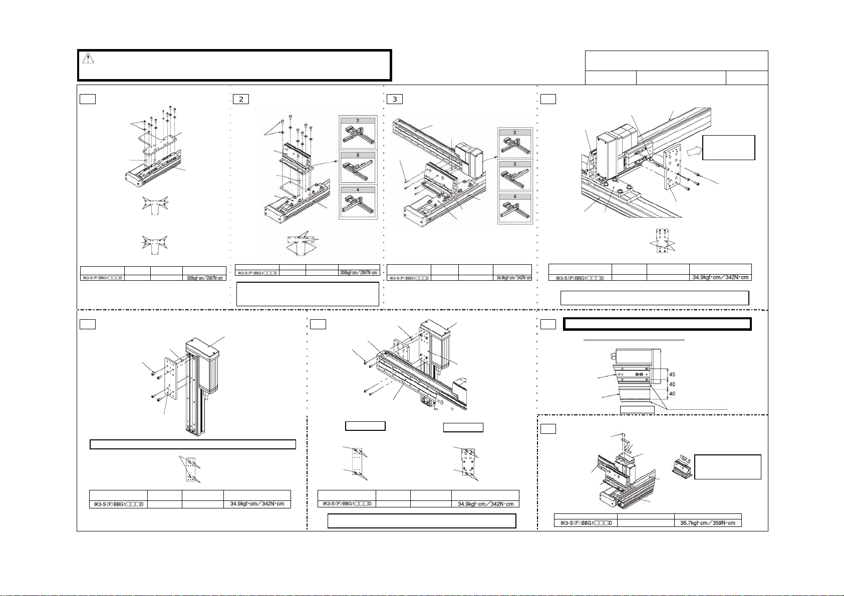
XYB + base fixed type: Single slider type
IK3-S(P)BBS
DWG. No. GMM07-058E 1/2
Parallel pin (1 pc or 2 pcs)
[1] XY bracket
[2] Plate X
X-axis
Screw lock holes:
Model Parallel pin
Note: To ensure squareness of the X-axis and Y-axis, place one parallel pin.
The following procedures apply to configurations with a cable bearer.
usting the squareness of the X-axis and Y-axis, affix the hex head bolt.
After ad
5.5
∅5h7 x 14
Install the X-axis and guide rail X.
X-axis
[5] Guide rail X
Bottom view
Hex socket-head bolt (2 pcs)
Hex nut (2 pcs)
Y-axis
[1] XY bracket
Model Hex socket-head bolt Tightening torque
[8] Bearer mounting bracket 1
Z-axis
M4 x 8 mm
Y-axis
Screw lock holes: ∅5.5
Parallel pin holes:
Hex socket-head
bolt
M5 x 12 mm
the base with the end
face of guide r ail X.
X-axis
[5] Guide rail X
After installing plate
YZ1, move the Y-axis
slider toward the
counter-motor end.
Hex socket-head bolt
[3] Plate YZ1
Tightening torque
lign the end face of
Set the dimension from the
side face of the XY bracket to
the tip of bearer mounting
bracket 1
(4 pcs)
5
8] to 152.5 mm.
Page 12

(
8
Hex socket-head countersunk (4 pcs)
Z-axis
Y-axis
[8] Bearer mounting
bracket 1
[Installation of ca ble bearer 1 [7] on bearer mounting br a cket 1 [8]]
Model
[Installation of cable bearer 1 [7] on guide rail X [5]]
Model
11
Y-axis
[3] Guide rail Y
Hex socket-head countersunk (4 pcs)
Hex nut (4 pcs)
[11] Bearer mounting
bracket 2
[Installation of cable b earer 2 [10] on guide rail Y [9]]
Model
[Installation of cable bearer 2 [10] on bearer mounting bracket 2 [11]]
Model
Hex socket-head
countersunk
Hex socket-head
countersunk
Hex socket-head
countersunk
Hex socket-head
countersunk
Hex head bolt countersunk (4 pcs)
[7] Cable bearer 1
[5] Guide rail X
Tightening torque
M3 x 6 mm
Tightening torque
M3 x 6 mm
[10] Cable bearer 2
Hex socket-head countersunk (4 pcs)
Tightening torq ue
M3 x 6 mm
Tightening torq ue
M3 x 6 mm
Hex nut (4 pcs)
X-axis
Align the end face of cable
bearer 1 [7] with the end
face of guide r ail X [5].
Z-axis
9
[1] T-slot in XY bracket
Z-axis
Y-axis
[9] Guide rail Y
Model Hex socket-head bolt Tightening torque
Installation position of cable bearer 2 [10]
[9] Guide rail Y
Y-axis st r ok e
50 mm 81.5
100 mm 106.5
150 mm 131.5
200 mm 156.5
250 mm 181.5
300 mm 206.5
350 mm 231.5
400 mm 256.5
M4 x 8 mm
Y-axis
See the table below.
Length from end face of guide rail Y
(front side) to fixed end of bearer
Align the end face of guide
rail Y [9] with the end face
of the XY bracket [1].
X-axis
Hex socket-head bolt (3 pcs)
Hex nut (3 pcs)
[10] Cable bearer 2
XYB + base fixed type: Single slider type
IK3-S(P)BBS
DWG. No. GMM07-058E 2/2
10
Y-axis
[9] Guide rail Y
Screw lock holes: ∅5.5
Model Hex s o c ket-head bolt Tightening torque
12
Arrange the wires so that each axis will not contact the cables and
connectors when the axis is moved over its entire stroke.
(Note) If you want to move the actuator with brake by hand, connect the
controller and supply the power and then set the brake release switch to
the release
* Refer to “Cable affixing method: GMM07-060” for affixing of cables.
[3] Plate YZ1
Z-axis
Hex socket-head bolt (2 pcs)
X-axis
[11] Bearer mounting bracket 2
M5 x 10 mm
RLS) side.
Page 13
g
a
ead bolt
∅
∅
j
∅
∅
∅
∅
j
A
[
Note: z Although the corners of each part have been chamfered, exercise due caution during
assembly to prevent injury. If necessary, wear gloves and other protective gears.
z Exercise due caution durin
[Tools] Allen wrench, spanner wrench, ruler
1
Hex socket head
bolt + plain washer
(8 pcs)
Parallel pin (2 pcs)
Screw lock holes
Screw lock holes
Combination directions 1, 3
Screw lock holes
Parallel pin holes
Screw lock holes
Combination directions 2, 4
Model
Parallel pin
∅8h7 x 18
Screw lock holes
Parallel pin holes
Screw lock holes
Screw lock holes
Screw lock holes
Hex
socket-head bolt
M8 x 20 mm
5
Parallel pin (1 pc or 2 pcs)
Hex socket-head bolt (4 pcs)
[4] Plate YZ2
Note: On some models, only one parallel pin may be accommodated depending on the axis.
Parallel pin holes:
4
Model Parallel pin
∅4h7 x 10
assembly to prevent pinching of your hands and fingers.
With combination directions
2 through 4, the bracket
directi o n i s different .
[2] Plate X
X-axis
2
Hex head bolt +
high-tension
washer (6 pcs)
[1] XY bracket
Parallel pin
(1 pc or 2 pcs)
[2] Plate X
Tightening torque
Screw lock holes: ∅9
Model
Note: To ensure squareness of the X-axis and Y-axis, place one
parallel pin.
After adjusting the squareness of the X-axis and Y-axis,
ffix the hex h
Screw lock holes: ∅9
Screw lock holes:
Parallel pin
Hex head bolt Tightening torque
M8 x 20 mm
∅8h7 x 18
.
6
Z-axis
Hex socket-head
bolt (4 pcs)
Parallel pin
holes: ∅4
Screw lock holes: ∅5.5
Screw lock holes: ∅5.5
Hex
socket-head bolt
M5 x 12 mm
Tightening torque
Parallel pin
holes: ∅4
X-axis
Parallel pin holes:
Note: To ensure squareness of the Y-axis and Z-axis, place one parallel pin.
3
Hex socket-head
bolt (4 pcs)
With combination directions 2 through
4, the actuator direction is different.
Y-axis
Parallel pin (1 pc or 2 pcs)
8
9
Model
Parallel pin (1 pc or 2 pcs)
[3] Plate YZ1
Y-axis
[4] Plate YZ2
Screw lock holes: ∅5.5
Screw lock holes: ∅5.5
Model Parallel pin
After ad
∅4h7 x 10
usting the squareness of the Y-axis and Z-axis, affix the hex head bolt.
Parallel pin
∅4h7 x 10
Parallel pin
holes: ∅4
Parallel pin
holes: ∅4
Hex
socket-head bolt
M5 x 10 mm
[3] Plate YZ1
[1] XY bracket
[2] Plate X
Hex
socket-head bolt
M5 x 15 mm
Z-axis
[4] Plate YZ2
Screw lock holes: ∅5.5
Screw lock holes: ∅5.5
Tightening torque
X-axis
Tightening
torque
XYB + base fixed type: Double slider type
IK3-S(P)BBD
DWG. No. GMM07-059E 1/2
4
[1] XY bracket
Parallel pin (1 pc or 2 pcs)
[2] Plate X
X-axis
Screw lock holes:
Model Parallel pin
Note: To ensure squareness of the X-axi s and Y-axis, place one paralle l pin.
After ad
∅5h7 x 14
usting the squareness of the X-axis and Y-axis, affix the hex head bolt.
The following procedures apply to configurations with a cable bearer.
7
Install the X-axis and guide rail X.
X-axis
[5] Guide rail X
Bottom view
8
Hex socket-head bolt (2 pcs)
Hex nut (2 pcs)
[8] Bearer mounting bracket 1
Y-axis
[1] XY bracket
Model Hex socket-head bolt Tightening torque
5.5
Hex socket-head
Z-axis
M4 x 8 mm
Y-axis
[3] Plate YZ1
Screw lock holes:
Parallel pin holes:
bolt
M5 x 12 mm
X-axis
[5] Guide rail X
lign the end face of
the base with the end
face of guide rail X.
After installing plate
YZ1, move the Y-axis
slider toward the
counter-motor end.
Hex socket-head bolt
(4 pcs)
5.5
5
Tightening torque
Set the dimension from the
side face of the XY bracket to
the tip of bear e r mounting
bracket 1
8] to 152.5 mm.
* This assembly procedure applies to combination direction 1. With other combination directions such as 2 through 4, the actuator and bracket directions are different. If you are using combination direction 2 through 4, assemble
the parts by referring to this drawing.
Page 14

(
9
Hex socket-head bolt (4 pcs)
Z-axis
Y-axis
[8] Bearer mounting
bracket 1
[Installation of cable bearer 1 [7] on bearer mounting bracket 1 [8]]
Model
[Installation of cabl e bearer 1 [7] on guide rail X [5]]
Model
12
Y-axis
[3] Guide rail Y
Hex socket-head countersunk (4 pcs)
Hex nut (4 pcs)
[11] Bearer mounting
bracket 2
[Installation of cable bearer 2 [10] on guide rail Y [9]]
Model
[Installation of cable bearer 2 [10] on bearer mounting bracket 2 [11]]
Model
Hex socket-head
countersunk
M3 x 6 mm
Hex socket-head
countersunk
M3 x 6 mm
Hex socket-head
countersunk
Hex socket-head
countersunk
[7] Cable bearer 1
[5] Guide rail X
[10] Cable bearer 2
Hex socket-head bolt (4 pcs)
M3 x 6 mm
M3 x 6 mm
Hex head bolt countersunk (4 pcs)
Hex nut (4 pcs)
X-axis
Align the end face of cable
bearer 1 [7] with the end
face of guide rail X [5].
Tightening torque
Tightening torque
Tightening torque
Tightening torque
Z-axis
10
[1] T-slot in XY bracket
Z-axis
Y-axis
[9] Guide rail Y
Model Hex socket-head bolt Tightening torque
Installation position of cable bearer 2 [10]
[9] Guide rail Y
Y-axis str o k e
50 mm 81.5
100 mm 106.5
150 mm 131.5
200 mm 156.5
250 mm 181.5
300 mm 206.5
350 mm 231.5
400 mm 256.5
M4 x 8 mm
Y-axis
See the table below.
Length from end face of guide rail Y
(front side) to fixed end of bear er
Align the end face of guide
rail Y [9] with the end face
of the XY bracket [1].
Hex socket-head bolt (3 pcs)
Hex nut (3 pcs)
X-axis
[10] Cable bearer 2
XYB + base fixed type: Double slider type
IK3-S(P)BBD
DWG. No. GMM07-059E 2/2
11
Y-axis
[9] Guide rail Y
Model Hex socket-head bolt Tightening torque
13
Arrange the wires so that each axis will not contact the cables and
connectors when the axis is moved over its entire stroke.
(Note) If you want to move the actuator with brake by hand, connect the
controller and supply the power and then set the brake release switch to
the release
* Refer to “Cable affixing method: GMM07-060” for affixing of cables.
[3] Plate YZ1
[11] Bearer mounting bracket 2
M5 x 10 mm
RLS) side.
Z-axis
Hex socket-head bolt (2 pcs)
X-axis
Page 15

g
A
g
g
Note: z Although the corners of each part have been chamfered, exercise due caution during
assembly to prevent injury. If necessary, wear gloves and other protective gears.
z Exercise due caution durin
assembly to prevent pinching of your hands and fingers.
XY base fixed type
ffixing to XY bracket [1] Affixing to cable bearer 1 [5]
Y-axis
[5] Cable
bearer 1
Use the T-slot to
affix the cables.
Tie-mount KR5G5 (HellermannTyton)
Hex socket-head countersunk M4-8
Hex nut
Affix the cables
usin
an Insulock.
[1] XY bracket
Upright type
Z-axis
Affixing to XY bracket [1]
Use the cable affixing
holes to affix t he cables.
Tie-mount KR5G5
(HellermannTyton)
Hex socket-head
countersunk M4-8
Affix the cables
usin
an Insulock.
Y-axis
[5] Cable bearer 1
Use an Insulock to affix each cable
directly to cable bearer 1 [5].
[1] XZ bracket
Use this part
to affix the
cables.
Cable affixing holes
(Affix from the back
side.)
Cable affixing method
DWG. No. GMM07-060E 1/2
Crossed type
Affixing to Z-axis
[4] Cable bearer 1
Secure the cables
together to the
motor cover.
Z-axis
Tie-mount MB-1
(HellermannTyton)
Hex socket-head countersunk M3-8
Hex nut
First, remove the thin
head bolts (2 locations).
Next, affix the cables
using an Insulock.
Note: Since the hex socket on the thin head bolt is small, the hex socket may
be stripped (damaged) depending on how the bolt is loosened. Exercise
due caution when loosening the thin head bolts.
[4] Cable bearer 1
Z-axis
XZ bracket
* The cable affixing method shown above assumes a Z-axis stroke of 50 mm.
If the Z-axis stroke is more than 50 mm, lay the cables straight when affixing, instead of bending them as shown in the figure.
Note: Arrange the wires so that each axis will not contact the cables and connectors when the axis is moved over its entire stroke. If you want to move the actuator with brake by hand, connect the controller and supply the power and then set the brake release
switch to the release (RLS) side.
Cable bearer
Bound the cables using
an Insulock.
Page 16

A
g
y
g
A
A
XY base fixed type
Between Z-axis and cable bearer 2
1
Tie-mount installation direction
Between Y-axis and cable bearer 1
2
Y-axis
Cable bearer 1
Z-axis cable
connector
Z-axis
Affixing to plate YZ1 [1]
Y-axis cable connector
Cable affixing method
ffixing to plate YZ1 [3] Affixing to cable bearer
Use this part to
Tie-mount installation direction
Tie-mount KR5G5 (HellermannTyton)
Hex socket-head countersunk M4-8
Install a tie-mount on plate YZ1 [3] and
affix the cable s usin
Use plate YZ1 to
affix the cables.
Use the T-slot to
affix the cables.
Hex socket countersunk bolt M4-8
Tie-mount KR5G5
(HellermannTyton)
Brass spacer
Plain washer
Hex nut
Affix the cables using
an Insulock.
Cable affixing holes
an Insulock.
3
[3] Plate YZ1
Between cable bearer 1 and cable bearer 2
ffixing to cable bearer 1 [10]
Use this part to
affix the cables.
Y-axis
Y-axis cable
Z-axis cable
Use an Insulock to affix
each cable dire ct ly t o c able
bearer 1 [5].
affix the cables.
Cable bearer 2
Use an Insulock to affix each cable
directl
to cable bearer 2 [10].
Y-axis
Affix the cable s us ing
an Insulock.
Z-axis
Affix the cables directly
to cable bearer 2 [10]
an Insulock.
usin
Use the T-slot to
affix the cables.
Tie-mount MB-1 (HellermannTyton)
Hex socket-head countersunk M-8
Affix the cables using
an Insulock.
4
Between cable bearer 1 and cable bearer 2
X-axis
DWG. No. GMM07-060E 2/2
Cable bearer 2
Z-axis
ffixing to cable bearer 1 [10]
Cable bearer 1
Use this part to
affix the cables.
Use an Insulock to affix
each cable directly to cable
bearer 1 [5].
Note: Arrange the wires so that each axis will not contact the cables and connectors when the axis is moved over its entire stroke. If you want to move the actuator with brake by hand, connect the controller and supply the power and then set the brake release
switch to the release (RLS) side.
 Loading...