

Page 1

Page 2

Page 3

Before Use
Thank you for purchasing our product.
This Operation Manual describes all necessary information to operate this product safely such as
the operation procedure, structure and maintenance procedure.
Before operation, read this manual carefully and fully understand it to operate this product safely.
The CD or DVD that comes with the product contains instruction manuals for IAI products.
For a use of the products, print out or display on your personal computer the necessary pages of
the applicable Operation Manuals.
After reading the Operation Manuals, be sure to keep them in a convenient place easily accessible
to the personnel using this product.
[Important]
x This Operation Manual is original.
x IAI shall not be liable whatsoever for any loss or damage arising from the result of using the
product for any other purpose from what is noted in the manual.
x The information contained in this Operation Manual is subject to change without notice for the
purpose of production improvement.
x If you have any question or finding regarding the information contained in this Operation Manual,
contact our customer center or our sales office near you.
x Using or copying all or a part of this Operation Manual without permission is prohibited.
x The company names, names of products and trademarks of our company shown in the
sentences are registered trademarks.
Page 4

CE Marking
If a compliance with the CE Marking is required, please follow Overseas Standards Compliance
Manual (ME0287) that is provided separately.
Page 5

Table of Contents
Safety Guide············································································································ 1
Caution in Handling ·································································································8
Names of the Parts ·································································································· 9
1. Specifications Check······················································································· 11
1.1 Product Check··································································································· 11
1.1.1 Parts··················································································································· 11
1.1.2 Operation Manuals related to this product, which are contained in the DVD.··· 12
1.1.3 How to read the model plate··············································································13
1.1.4 How to read the model No.················································································ 14
1.2 Specification······································································································15
1.3 Option················································································································ 17
1.3.1 AQ Seal··············································································································17
1.3.2 Creep Sensor····································································································· 17
1.3.3 Home Limit Switch ····························································································· 17
1.3.4 Reversed-home Type·························································································17
1.3.5 Guide with Ball Retainer Mechanism·································································17
1.3.6 W Slider ············································································································· 17
1.4 Motor • Encoder Cables ····················································································18
1.4.1 Standard············································································································· 18
1.4.2 CE Type (Option Model code : EU)·································································23
2. Installation······································································································· 26
2.1 Transportation ··································································································· 26
2.2 Installation and Storage Environment ·······························································28
2.3 How to Install····································································································· 29
2.3.1 Orientation of the Actuator Installation·······························································29
2.3.2 Installation·········································································································· 30
3. Connection to the controller············································································35
4. Setting the Home Position ··············································································40
5. Maintenance inspection ·················································································· 41
5.1 Inspection Items and Inspection Schedule························································41
5.2 Visual inspection ·······························································································41
5.3 Cleaning ············································································································ 41
5.4 Internal Inspection·····························································································42
5.5 Internal Cleanup································································································42
5.6 Grease Supply ··································································································43
5.7 How to Inspect the Timing Belt··········································································44
5.7.1 Belt Tension Adjustment Method ·······································································45
5.8 How to Replace the Timing Belt ········································································47
5.9 Deceleration Belt Replacement·········································································54
5.10 Motor Replacement Process·············································································57
6. External Dimensions·······················································································61
6.1 IF-SA-60············································································································61
6.2 IF-SA-100··········································································································62
6.3 IF-MA-200 ·········································································································63
6.4 IF-MA-400 ·········································································································64
Page 6

7. Life·················································································································· 65
8. Warranty ·········································································································66
8.1 Warranty Period ································································································66
8.2 Scope of the Warranty·······················································································66
8.3 Honoring the Warranty ······················································································ 66
8.4 Limit in Responsibility························································································ 67
8.5 Conditions of Conformance with Applicable Standards/Regulations, Etc., and
Applications·······································································································67
8.6 Other Items Excluded from Warranty ································································67
Change History······································································································ 68
Page 7

1
Safety Guide
“Safety Guide” has been written to use the machine safely and so prevent personal injury or
property damage beforehand. Make sure to read it before the operation of this product.
Safety Precautions for Our Products
The common safety precautions for the use of any of our robots in each operation.
No.
Operation
Description
Description
1 Model
Selection
Ɣ This product has not been planned and designed for the application
where high level of safety is required, so the guarantee of the protection
of human life is impossible. Accordingly, do not use it in any of the
following applications.
1) Medical equipment used to maintain, control or otherwise affect
human life or physical health.
2) Mechanisms and machinery designed for the purpose of moving or
transporting people (For vehicle, railway facility or air navigation
facility)
3) Important safety parts of machinery (Safety device, etc.)
Ɣ Do not use the product outside the specifications. Failure to do so may
considerably shorten the life of the product.
Ɣ Do not use it in any of the following environments.
1) Location where there is any inflammable gas, inflammable object or
explosive
2) Place with potential exposure to radiation
3) Location with the ambient temperature or relative humidity exceeding
the specification range
4) Location where radiant heat is added from direct sunlight or other
large heat source
5) Location where condensation occurs due to abrupt temperature
changes
6) Location where there is any corrosive gas (sulfuric acid or
hydrochloric acid)
7) Location exposed to significant amount of dust, salt or iron powder
8) Location subject to direct vibration or impact
Ɣ For an actuator used in vertical orientation, select a model which is
equipped with a brake. If selecting a model with no brake, the moving
part may drop when the power is turned OFF and may cause an
accident such as an injury or damage on the work piece.
Page 8

2
No.
Operation
Description
Description
2 Transportation Ɣ When carrying a heavy object, do the work with two or more persons or
utilize equipment such as crane.
Ɣ When the work is carried out with 2 or more persons, make it clear who
is to be the leader and who to be the follower(s) and communicate well
with each other to ensure the safety of the workers.
Ɣ When in transportation, consider well about the positions to hold, weight
and weight balance and pay special attention to the carried object so it
would not get hit or dropped.
Ɣ Transport it using an appropriate transportation measure.
The actuators available for transportation with a crane have eyebolts
attached or there are tapped holes to attach bolts. Follow the
instructions in the operation manual for each model.
Ɣ Do not step or sit on the package.
Ɣ Do not put any heavy thing that can deform the package, on it.
Ɣ When using a crane capable of 1t or more of weight, have an operator
who has qualifications for crane operation and sling work.
Ɣ When using a crane or equivalent equipments, make sure not to hang a
load that weighs more than the equipment’s capability limit.
Ɣ Use a hook that is suitable for the load. Consider the safety factor of the
hook in such factors as shear strength.
Ɣ Do not get on the load that is hung on a crane.
Ɣ Do not leave a load hung up with a crane.
Ɣ Do not stand under the load that is hung up with a crane.
3 Storage and
Preservation
Ɣ The storage and preservation environment conforms to the installation
environment. However, especially give consideration to the prevention
of condensation.
Ɣ Store the products with a consideration not to fall them over or drop due
to an act of God such as earthquake.
4 Installation
and Start
(1) Installation of Robot Main Body and Controller, etc.
Ɣ Make sure to securely hold and fix the product (including the work part).
A fall, drop or abnormal motion of the product may cause a damage or
injury.
Also, be equipped for a fall-over or drop due to an act of God such as
earthquake.
Ɣ Do not get on or put anything on the product. Failure to do so may
cause an accidental fall, injury or damage to the product due to a drop of
anything, malfunction of the product, performance degradation, or
shortening of its life.
Ɣ When using the product in any of the places specified below, provide a
sufficient shield.
1) Location where electric noise is generated
2) Location where high electrical or magnetic field is present
3) Location with the mains or power lines passing nearby
4) Location where the product may come in contact with water, oil or
chemical droplets
Page 9

3
No.
Operation
Description
Description
(2) Cable Wiring
Ɣ Use our company’s genuine cables for connecting between the actuator
and controller, and for the teaching tool.
Ɣ Do not scratch on the cable. Do not bend it forcibly. Do not pull it. Do not
coil it around. Do not insert it. Do not put any heavy thing on it. Failure to
do so may cause a fire, electric shock or malfunction due to leakage or
continuity error.
Ɣ Perform the wiring for the product, after turning OFF the power to the
unit, so that there is no wiring error.
Ɣ When the direct current power (+24V) is connected, take the great care
of the directions of positive and negative poles. If the connection
direction is not correct, it might cause a fire, product breakdown or
malfunction.
Ɣ Connect the cable connector securely so that there is no disconnection
or looseness. Failure to do so may cause a fire, electric shock or
malfunction of the product.
Ɣ Never cut and/or reconnect the cables supplied with the product for the
purpose of extending or shortening the cable length. Failure to do so
may cause the product to malfunction or cause fire.
4 Installation
and Start
(3) Grounding
Ɣ The grounding operation should be performed to prevent an electric
shock or electrostatic charge, enhance the noise-resistance ability and
control the unnecessary electromagnetic radiation.
Ɣ For the ground terminal on the AC power cable of the controller and the
grounding plate in the control panel, make sure to use a twisted pair
cable with wire thickness 0.5mm
2
(AWG20 or equivalent) or more for
grounding work. For security grounding, it is necessary to select an
appropriate wire thickness suitable for the load. Perform wiring that
satisfies the specifications (electrical equipment technical standards).
Ɣ Perform Class D Grounding (former Class 3 Grounding with ground
resistance 100: or below).
Page 10

4
No.
Operation
Description
Description
4 Installation
and Start
(4) Safety Measures
Ɣ When the work is carried out with 2 or more persons, make it clear who
is to be the leader and who to be the follower(s) and communicate well
with each other to ensure the safety of the workers.
Ɣ When the product is under operation or in the ready mode, take the
safety measures (such as the installation of safety and protection fence)
so that nobody can enter the area within the robot’s movable range.
When the robot under operation is touched, it may result in death or
serious injury.
Ɣ Make sure to install the emergency stop circuit so that the unit can be
stopped immediately in an emergency during the unit operation.
Ɣ Take the safety measure not to start up the unit only with the power
turning ON. Failure to do so may start up the machine suddenly and
cause an injury or damage to the product.
Ɣ Take the safety measure not to start up the machine only with the
emergency stop cancellation or recovery after the power failure. Failure
to do so may result in an electric shock or injury due to unexpected
power input.
Ɣ When the installation or adjustment operation is to be performed, give
clear warnings such as “Under Operation; Do not turn ON the power!”
etc. Sudden power input may cause an electric shock or injury.
Ɣ Take the measure so that the work part is not dropped in power failure
or emergency stop.
Ɣ Wear protection gloves, goggle or safety shoes, as necessary, to secure
safety.
Ɣ Do not insert a finger or object in the openings in the product. Failure to
do so may cause an injury, electric shock, damage to the product or fire.
Ɣ When releasing the brake on a vertically oriented actuator, exercise
precaution not to pinch your hand or damage the work parts with the
actuator dropped by gravity.
5 Teaching Ɣ When the work is carried out with 2 or more persons, make it clear who
is to be the leader and who to be the follower(s) and communicate well
with each other to ensure the safety of the workers.
Ɣ Perform the teaching operation from outside the safety protection fence,
if possible. In the case that the operation is to be performed unavoidably
inside the safety protection fence, prepare the “Stipulations for the
Operation” and make sure that all the workers acknowledge and
understand them well.
Ɣ When the operation is to be performed inside the safety protection
fence, the worker should have an emergency stop switch at hand with
him so that the unit can be stopped any time in an emergency.
Ɣ When the operation is to be performed inside the safety protection
fence, in addition to the workers, arrange a watchman so that the
machine can be stopped any time in an emergency. Also, keep watch on
the operation so that any third person can not operate the switches
carelessly.
Ɣ Place a sign “Under Operation” at the position easy to see.
Ɣ When releasing the brake on a vertically oriented actuator, exercise
precaution not to pinch your hand or damage the work parts with the
actuator dropped by gravity.
* Safety protection Fence : In the case that there is no safety protection
fence, the movable range should be indicated.
Page 11

5
No.
Operation
Description
Description
6 Trial
Operation
Ɣ When the work is carried out with 2 or more persons, make it clear who
is to be the leader and who to be the follower(s) and communicate well
with each other to ensure the safety of the workers.
Ɣ After the teaching or programming operation, perform the check
operation one step by one step and then shift to the automatic
operation.
Ɣ When the check operation is to be performed inside the safety
protection fence, perform the check operation using the previously
specified work procedure like the teaching operation.
Ɣ Make sure to perform the programmed operation check at the safety
speed. Failure to do so may result in an accident due to unexpected
motion caused by a program error, etc.
Ɣ Do not touch the terminal block or any of the various setting switches in
the power ON mode. Failure to do so may result in an electric shock or
malfunction.
7 Automatic
Operation
Ɣ Check before starting the automatic operation or rebooting after
operation stop that there is nobody in the safety protection fence.
Ɣ Before starting automatic operation, make sure that all peripheral
equipment is in an automatic-operation-ready state and there is no
alarm indication.
Ɣ Make sure to operate automatic operation start from outside of the
safety protection fence.
Ɣ In the case that there is any abnormal heating, smoke, offensive smell,
or abnormal noise in the product, immediately stop the machine and
turn OFF the power switch. Failure to do so may result in a fire or
damage to the product.
Ɣ When a power failure occurs, turn OFF the power switch. Failure to do
so may cause an injury or damage to the product, due to a sudden
motion of the product in the recovery operation from the power failure.
Page 12
6
No.
Operation
Description
Description
8 Maintenance
and
Inspection
Ɣ When the work is carried out with 2 or more persons, make it clear who
is to be the leader and who to be the follower(s) and communicate well
with each other to ensure the safety of the workers.
Ɣ Perform the work out of the safety protection fence, if possible. In the
case that the operation is to be performed unavoidably inside the safety
protection fence, prepare the “Stipulations for the Operation” and make
sure that all the workers acknowledge and understand them well.
Ɣ When the work is to be performed inside the safety protection fence,
basically turn OFF the power switch.
Ɣ When the operation is to be performed inside the safety protection
fence, the worker should have an emergency stop switch at hand with
him so that the unit can be stopped any time in an emergency.
Ɣ When the operation is to be performed inside the safety protection
fence, in addition to the workers, arrange a watchman so that the
machine can be stopped any time in an emergency. Also, keep watch on
the operation so that any third person can not operate the switches
carelessly.
Ɣ Place a sign “Under Operation” at the position easy to see.
Ɣ For the grease for the guide or ball screw, use appropriate grease
according to the Operation Manual for each model.
Ɣ Do not perform the dielectric strength test. Failure to do so may result in
a damage to the product.
Ɣ When releasing the brake on a vertically oriented actuator, exercise
precaution not to pinch your hand or damage the work parts with the
actuator dropped by gravity.
Ɣ The slider or rod may get misaligned OFF the stop position if the servo
is turned OFF. Be careful not to get injured or damaged due to an
unnecessary operation.
Ɣ Pay attention not to lose the cover or untightened screws, and make
sure to put the product back to the original condition after maintenance
and inspection works.
Use in incomplete condition may cause damage to the product or an
injury.
* Safety protection Fence : In the case that there is no safety protection
fence, the movable range should be indicated.
9 Modification
and Dismantle
Ɣ Do not modify, disassemble, assemble or use of maintenance parts not
specified based at your own discretion.
10 Disposal Ɣ When the product becomes no longer usable or necessary, dispose of it
properly as an industrial waste.
Ɣ When removing the actuator for disposal, pay attention to drop of
components when detaching screws.
Ɣ Do not put the product in a fire when disposing of it.
The product may burst or generate toxic gases.
11 Other Ɣ Do not come close to the product or the harnesses if you are a person
who requires a support of medical devices such as a pacemaker. Doing
so may affect the performance of your medical device.
Ɣ See Overseas Specifications Compliance Manual to check whether
complies if necessary.
Ɣ For the handling of actuators and controllers, follow the dedicated
operation manual of each unit to ensure the safety.
Page 13

7
Alert Indication
The safety precautions are divided into “Danger”, “Warning”, “Caution” and “Notice” according to
the warning level, as follows, and described in the Operation Manual for each model.
Level Degree of Danger and Damage Symbol
Danger
This indicates an imminently hazardous situation which, if the
product is not handled correctly, will result in death or serious
injury.
Danger
Warning
This indicates a potentially hazardous situation which, if the
product is not handled correctly, could result in death or serious
injury.
Warning
Caution
This indicates a potentially hazardous situation which, if the
product is not handled correctly, may result in minor injury or
property damage.
Caution
Notice
This indicates lower possibility for the injury, but should be kept to
use this product properly.
Notice
Page 14

8
Caution in Handling
1. Do not have the settings of speed and acceleration/deceleration exceeding
the rated values.
An operation with speed and acceleration/deceleration beyond the allowable range may
cause an abnormal noise, vibration, malfunction or shortened life.
When having an interpolating operation for combined axes, set the smallest value among the
combined axes for each of speed and acceleration/deceleration settings.
2. Set the allowable load moment within the allowable range.
Use the product with the applied load moment within the allowable range.
An operation with the load beyond the allowable load moment may cause an abnormal noise,
vibration, malfunction or shortened life. If it is extreme, flaking may occur on the guide.
3. Set the overhang length within the allowable range.
Have the overhang length of the load within the allowable range. The overhang length above
the allowable range may cause vibration or abnormal noise.
4. Back and forth operation in a short distance may cause wear of grease.
Continuous back and forth operation within a distance less than 30mm may cause wear of
grease.
As a reference, have approximately 5 cycles of back and forth operation in a distance more
than 50mm in every 5,000 to 10,000 cycles to regenerate the oil film. Keep using the actuator
with the grease worn out may cause malfunction. If it is extreme, flaking may occur on the
guide.
5. Ensure use of the product in the specified conditions, environments and
ranges.
Operation out of the specified conditions could cause a drop in performance or malfunction of the
product.
Page 15

9
Names of the Parts
In this manual, the right and left sides of the actuator are expressed in the way it is placed
horizontally as shown in the figure below, and is looked at from the motor side.
Page 16

10
Page 17

11
1. Specifications Check
1.1 Product Check
The standard configuration of this product is comprised of the following parts.
See the component list for the details of the enclosed components. If you find any broken or
missing parts, contact your local IAI distributor.
1.1.1 Parts
No. Part Name Model Quantity Remarks
1 Main Body
Refer to “How to read
the model plate”, “How
to read the model No.”
1
Accessories
2 Motor • Encoder Cables
(Note 1)
1 set
3 In-House Made Seals 1 set
4 First Step Guide 1
5 Operating Manual (CD/DVD) 1
6 Safety Guide 1
Note 1 The motor/encoder cables differ between the standard model and robot cable.
[Refer to 1.4 Motor • Encoder Cables.]
1. Specications Check
Page 18

1. Specications Check
12
1.1.2 Operation Manuals related to this product, which are contained in the DVD.
Shown below is a list of the operation manuals for the controllers related to this product which
is recorded in Operation Manual (DVD).
(1) XSEL-J/K Controller
No. Name Manual No.
1 XSEL-J/K Controller Operation Manual ME0116
2 PC Software IA-101-X-MW/IA-101-X-USBMW Operation Manual ME0154
3 Teaching Pendant SEL-T/TD/TG Operation Manual ME0183
4 Teaching Pendant IA-T-X/XD Operation Manual ME0160
5 DeviceNet Operation Manual ME0124
6 CC-Link Operation Manual ME0123
7 PROFIBUS Operation Manual ME0153
8 XSEL Ethernet Operation Manual ME0140
9 Multi-Point I/O Board Operation Manual ME0138
10
Multi-Point I/O Board Dedicated Terminal Board Operation
Manual
ME0139
(2) XSEL-P/Q Controller
No. Name Manual No.
1 XSEL-P/Q Controller Operation Manual ME0148
2 XSEL-P/Q/PX/QX RC Gateway Function Operation Manual ME0188
3 PC Software IA-101-X-MW/IA-101-X-USBMW Operation Manual ME0154
4 Teaching Pendant SEL-T/TD/TG Operation Manual ME0183
5 Teaching Pendant IA-T-X/XD Operation Manual ME0160
6 DeviceNet Operation Manual ME0124
7 CC-Link Operation Manual ME0123
8 PROFIBUS Operation Manual ME0153
(3) SSEL Controller
No. Name Manual No.
1 SSEL Controller Operation Manual ME0157
2 PC Software IA-101-X-MW/IA-101-X-USBMW Operation Manual ME0154
3 Teaching Pendant SEL-T/TD/TG Operation Manual ME0183
4 Teaching Pendant IA-T-X/XD Operation Manual ME0160
5 DeviceNet Operation Manual ME0124
6 CC-Link Operation Manual ME0123
7 PROFIBUS Operation Manual ME0153
Page 19
13
(4) SCON Controller
No. Name Manual No.
1 SCON Controller Operation Manual ME0161
2 SCON-CA Controller Operation Manual ME0243
3 PC Software RCM-101-MW/RCM-101-USB Operation Manual ME0155
4 Teaching Pendant CON-T/TG Operation Manual ME0178
5 Touch Panel Teaching CON-PT/PD/PG Operation Manual ME0227
6 Simplified Teaching Pendant RCM-E Operation Manual ME0174
7 Data setter RCM-P Operation Manual ME0175
8 Touch Panel Display RCM-PM-01 Operation Manual ME0182
9 DeviceNet Operation Manual ME0124
10 CC-Link Operation Manual ME0123
11 PROFIBUS Operation Manual ME0153
1.1.3 How to read the model plate
Model
Serial number
MODEL RS-I-30-50-360-T2-S-K
SERIAL No. 900014180 MADE IN JAPAN
1. Specications Check
Page 20

1. Specications Check
14
1.1.4 How to read the model No.
Note 1 Identification for IAI use only: This may be marked for the purpose of IAI. It is not an ID to describe
the model code.
I F - S A 1 L - I - 6 0 - 2 0 0 - T 1 - S - A Q - * *
<Option>
AQ : AQ Seal
C : Creep sensor
(CL : Located on the Other Side)
L : Home Limit Switch
(LL : Located on the Other Side)
NM : Reversed-home type
RT : Guide with Ball Retainer
Mechanism
W : W Slider
<Cable length>
N : None
S : 3m
M : 5m
XƑƑ : Specified Length
(Example: X07=7m)
<Applicable Controller>
T1 : XSEL-J/K
T2 : SCON
SSEL
XSEL-P/Q
<Stroke>
[Refer to 1.2 Specification.]
Series Name
<Type>
SA1L : Small, Standard
SA2L : Small, Motor Located on the Side
SA3L : Small, Motor Located on the Bottom
SA1R : Small, Motor on the Other Side
SA2R : Small,
Motor Horizontally Located on the Other
Side
SA3R : Small,
Motor Located on Bottom on the Other Side
MA1L : Medium, Standard
MA2L : Medium, Motor Located on the Side
MA3L : Medium, Motor Located on the Bottom
MA1R : Medium, Motor on the Other Side
MA2R : Medium,
Motor Horizontally Located on the Other
Side
MA3R : Medium,
Motor Located on Bottom on the Other Side
<Encoder type >
A : Absolute
I : Incremental
<Motor Type >
Identification for IAI use only
Note 1
Page 21

15
1.2 Specification
[1] Max. Speed
There is a limit in the maximum speed of the actuators.
Restriction on Speed (Unit: mm/s)
Stroke [mm]
Type
Motor Type
[W]
300 400 500 600 700 800 900 1000
60 1 to 1250
NM
100 1 to 1250
Stroke [mm]
Type
Motor Type
[W]
300 400 600 800 1000 1500 2000 2500
100 1 to 1250
WM
200 1 to 1250
Stroke [mm]
Type
Motor Type
[W]
1000 1500 2000 2500 3000
LM 400 1 to 1250
HM 400 1 to 2000
[2] Max. Acceleration Speed and Transportable Weight
When the transported weight is low, the acceleration/deceleration can be increased.
Size Slider
Motor Type
[W]
Acceleration/
Deceleration
[G]
Transportable
Weight [kg]
Rated Thrust
[N]
11NM Single 60 0.3 2 29
12NM Double 60 0.3 9 29
11NM Single 100 0.3 3 49
12NM Double 100 0.3 15 49
11WM Single 100 0.3 3 49
12WM Double 100 0.3 15 49
11WM Single 200 0.3 6 98
12WM Double 200 0.3 30 98
11LM Single 400 0.3 15 196
12LM Double 400 0.3 60 196
11HM Single 400 0.3 10 127
12HM Double 400 0.3 40 127
Caution: Do not have the settings of acceleration/deceleration exceeding the rated
values. It may cause vibration, malfunction or shortened life.
1. Specications Check
Page 22

1. Specications Check
16
[3] Driving System and Position Detector
Type
Motor Type
[W]
No. of Encoder
Pulses
Drive system
NM 60
NM 100
WM 100
WM 200
LM 400
HM 400
16384
*1
Timing belt
[4] Positioning Accuracy
Item Specification
Positioning Repeatability ± 0.08mm
Lost Motion 0.1mm or less
Page 23

17
1.3 Option
1.3.1 AQ Seal
By having the AQ Seal held on the guides and ball screw, lubricant is supplied on them, which
enables maintenance-free due to a multiplier effect caused by the use together with the
supply of grease.
The model code is indicated with an AQ.
1.3.2 Creep Sensor
It is a sensor to enable a high-speed home-return operation.
The model code is indicated with a C.
1.3.3 Home Limit Switch
In ordinary home-return operation, “pressing method” which the actuator is pressed against
the stopper and detects the Z-phase after reversed is adopted.
“Home limit switch” is an option that does not adopt this pressing method but adopts a
proximity sensor to perform the home-return operation.
The model code is indicated with an L.
1.3.4 Reversed-home Type
The home is set on the side opposite the motor.
The model code is indicated with an NM.
1.3.5 Guide with Ball Retainer Mechanism
By putting a spacer (retainer) between the guides, ball (steel) and ball, noise can be lowered
and the product life can be made longer at the same time.
The model code is indicated with an RT.
1.3.6 W Slider
A free slider which is not connected to the ball screw or driving belt can be added.
The model code is indicated with a W.
1. Specications Check
Page 24

1. Specications Check
18
1.4 Motor • Encoder Cables
1.4.1 Standard
The cables are in common for the actuators no matter the model type. The cables differ
depending on the corresponding controller.
Table for Controller and Applicable Motor • Encoder Cable
Controller XSEL-J/K XSEL-P/Q SSEL SCON
LS
Without
LS
With LS
Without
LS
With LS
Without
LS
With LS
Without
LS
With LS
Applicable
Cable
1), 2) 1), 2), 3) 1), 4) 1), 5) 1), 4) 1), 5) 1), 4) 1), 5)
1) Motor Cable CB-X-MAƑƑƑ
Enter the cable length (L) in ƑƑƑ (up to 30 m)
Example) 080=8m
[Minimum Bending Radius]
When used under moving condition : 51mm
When used in fixed condition : 34mm
Page 25
19
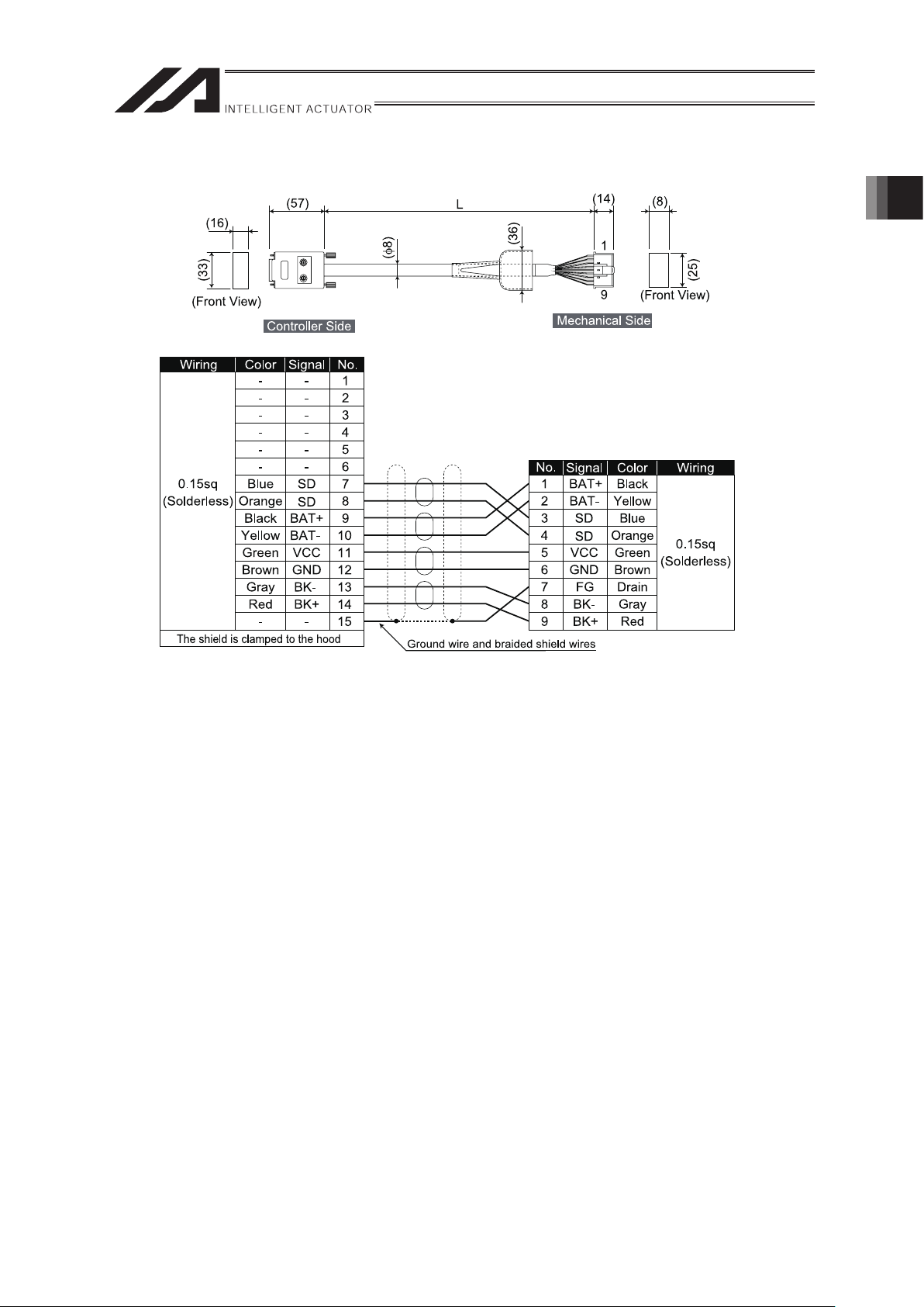
2) Encoder Cable CB-X-PAƑƑƑ
Enter the cable length (L) in ƑƑƑ (up to 30 m)
Example) 080=8m
[Minimum Bending Radius]
When used under moving condition : 44mm
When used in fixed condition : 29mm
1. Specications Check
Page 26
1. Specications Check
20
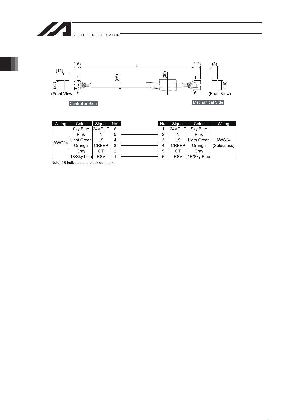
3) Limit Switch Cable CB-X-LCƑƑƑ
Enter the cable length (L) in ƑƑƑ (up to 30 m)
Example) 080=8m
[Minimum Bending Radius]
When used under moving condition : 33mm
When used in fixed condition : 22mm
Page 27

21
4) Encoder Cable CB-X1-PAƑƑƑ
Enter the cable length (L) in ƑƑƑ (up to 30 m)
Example) 080=8m
[Minimum Bending Radius]
When used under moving condition : 44mm
When used in fixed condition : 29mm
1. Specications Check
Page 28
1. Specications Check
22
5) Encoder Cable with LS CB-X1-PLAƑƑƑ
Enter the cable length (L) in ƑƑƑ (up to 30 m)
Example) 080=8m
[Minimum Bending Radius]
When used under moving condition : 54mm
When used in fixed condition : 36mm
Page 29
23
1.4.2 CE Type (Option Model code: EU)
The cables are in common for the actuators no matter the model type. The cables differ
depending on whether it is with or without LS.
Table for Controller and Applicable Motor • Encoder Cable
Controller XSEL-P/Q, SSEL, SCON
LS Without LS With LS
Applicable Cable 1), 2) 1), 3)
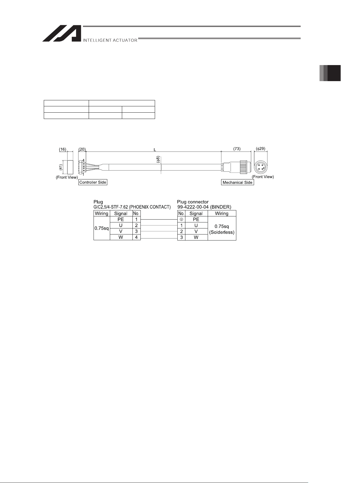
1) Motor Cable CB-XEU-MAƑƑƑ
Enter the cable length (L) in ƑƑƑ (up to 30 m)
Example) 080=8m
[Minimum Bending Radius]
When used under moving condition : 48mm
When used in fixed condition : 48mm
1. Specications Check
Page 30

1. Specications Check
24
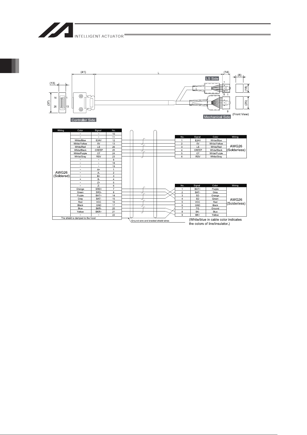
2) Encoder Cable CB-XEU1-PAƑƑƑ
(
φ
8)
Wiring Color Signal No.
WiringColorSignalNo.
AWG26
(Soldered)
AWG26
(Soldered)
- -
-
E24V
OV
LS
CREEP
OT
RSV
-
-
A+
A-
B+
B-
Z+
Z-
SRD+
SRD-
BAT+
BAT-
VCC
GND
BKR-
BKR+
-
10
11
12
26
25
24
23
9
18
19
1
2
3
4
5
6
7
8
14
15
16
17
20
21
22
-
-
-
-
-
-
-
-
-
-
-
-
-
-
-
Orange
Green
Purple
Gray
Red
Black
Blue
Yellow
-
The shield is clamped to the hood
(White/blue in cable color indicates the colors of line/insulator.)
Ground wire and braided shield wires
1
2
3
4
5
6
7
8
9
10
11
12
13
14
15
16
SD
SD
-
-
-
-
-
-
-
VCC
GND
BAT+
BAT-
BKR-
BKR+
Orange
Green
-
-
-
-
-
-
-
Red
Black
Purple
Gray
Blue
Yellow
Shield to be connected to earth sleeve
Enter the cable length (L) in ƑƑƑ (up to 30 m)
Example) 080=8m
[Minimum Bending Radius]
When used under moving condition : 44mm
When used in fixed condition : 29mm
Page 31
25
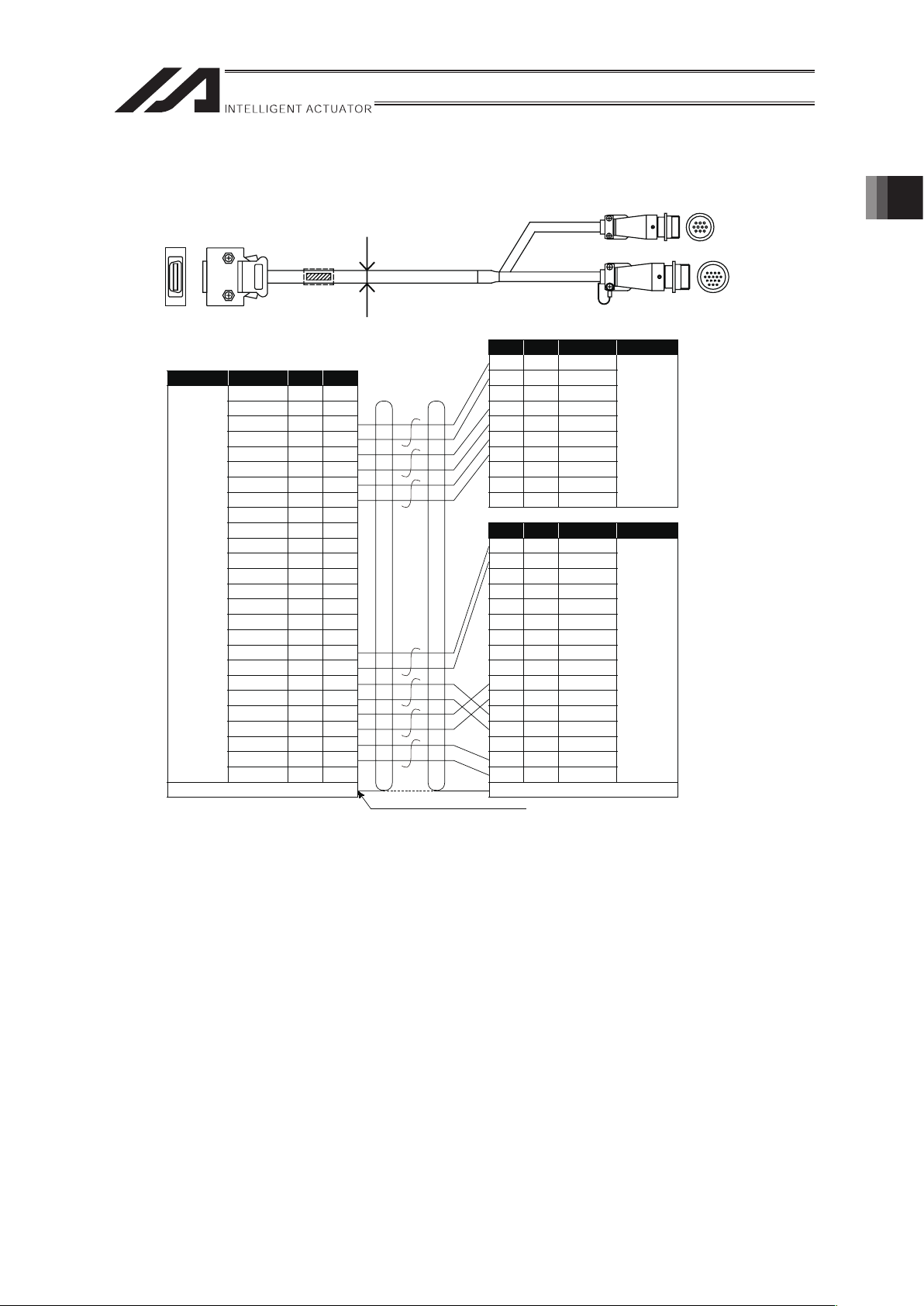
3) Encoder Cable CB-XEU1-PAƑƑƑ
(
φ
10)
Wiring Color Signal No.
AWG26
(Soldered)
AWG26
(Solderless)
AWG26
(Solderless)
-
-
White/Blue
White/Yellow
White/Red
White/Black
White/Purple
White/Gray
-
-
-
-
-
-
-
-
-
Green
Purple
Gray
Red
Black
Blue
Yellow
-
-
-
-
E24V
OV
LS
CREEP
OT
RSV
-
-
A+
A-
B+
Z+
B-
Z-
SRD+
SRD-
BAT+
BAT-
VCC
GND
BKR-
BKR+
-
-
1
2
3
4
5
6
7
8
10
19
1
2
3
5
4
6
7
8
14
10
11
12
13
25
26
24
23
9
18
15
16
17
20
21
22
9
E24V
OV
-
LS
CREEP
OT
RSV
-
-
-
White/Blue
White/Yellow
-
White/Red
White/Black
White/Purple
White/Gray
-
-
-
1
2
3
4
5
6
7
8
10
9
SD
SD
-
-
-
-
-
-
VCC
-
Orange
Green
-
-
-
-
-
-
Red
-
11
12
13
14
15
16
GND
BAT+
BAT-
-
BK-
BK+
Black
Purple
Gray
-
Blue
Yellow
The shield is clamped to the hood
(White/blue in cable color indicates the colors of line/insulator.)
Ground wire and braided shield wires
WiringColorSignalNo.
WiringColorSignalNo.
Shield to be connected to earth sleeve
Enter the cable length (L) in ƑƑƑ (up to 30 m)
Example) 080=8m
[Minimum Bending Radius]
When used under moving condition : 58mm
When used in fixed condition : 38mm
1. Specications Check
Page 32

2. Installation
26
2. Installation
2.1 Transportation
[1] Handling of the Robot
Pay attention to the following when carrying an actuator by itself.
(1) Handling of the Packed Product
Unless otherwise specified, the single axes at the delivery are packaged individually.
Please concern the handling of the unit so you would not hit or drop it while carrying.
x An operator should never attempt to carry a heavy package on their own.
x If the shipping box is to be left standing, it should be in a horizontal position.
x Do not step or sit on the package.
x Do not place on the carton any heavy object that may cause the carton to deform, or an
article whose shape allows a load to be concentrated at one point.
(2) Handling after Unpackaged
Do not attempt to hold the motor unit or cable when carrying the actuator, or pull the cables to
move the unit.
Make sure to hold the base area when handling the unpackaged actuator.
[2] Handling of Multi-Axes Type
Pay attention to the following when carrying the actuator with the axes being attached.
(1) Handling of the Packed Product
If an order for the product was made with the axes attached, we would build the product in
our factory, conduct the delivery inspection, affix on a wooden pallet and cover with the
frames to deliver the product.
If the actuator to be attached is a slider type, the slider is fixed in the package so it would not
accidentally move. Also for the actuator of the combined unit, the end is fixed so it would not
widely shake by the external vibration.
x The package is not applied with any special treatment that enables it to resist an impact
caused by a drop or crash. Handle it with care. Also, please note that the frame would not
endure load on the top. Do not attempt to put load on it.
x When suspending the package using belts, pass the belts from underneath the
reinforcement frames at the bottom of the base. When lifting with a forklift, also place the
forks underneath the base.
x Handle with care not to apply shock when putting it down.
Page 33

27
(2) Handling after Unpackaged
After unpackaged, handle the product that axes were attached in IAI factory following the
instructions below:
x Fix the sliders during transportation so they would not move accidently.
x Appropriately fix the end of the actuators if it is overhanging so it would not widely shake
with external vibration. If the actuator assembly is transported without the ends being
secured, do not apply an impact of 0.3G or more.
x In such cases as hanging the peripherals including the actuators with a belt, do not
attempt to attach the belt directly to the actuators and avoid the belt being touch the
actuators.
x Apply appropriate shock-proof methods to the belt and set it so the base part receives the
load.
x For Y-axis, support the end with another belt to maintain the stable horizontal orientation.
At the same time, pay attention not to apply load to the screw cover.
x Do not attempt to apply load to the brackets, covers or connector box mounted on the
main body.
Also, avoid the cables being pinched or caused an excessive deformation.
[3] Handling of the Robot Mounted on Mechanical Equipment (System)
When peripheral devices were attached by the customer and the unit is to be carried, also
follow the instructions described in [5.2.2 handling in unpackaged condition] for appropriate
handling.
2. Installation
Page 34

2. Installation
28
2.2 Installation and Storage Environment
[1] Installation
Do not use this product in the following environments.
It is generally the environment where a worker can work without any protection gear.
Also make sure to keep enough work space necessary for maintenance.
x Location exposed to radiant heat from a huge heat source such as the heat treatment
x Location where the surrounding air temperature exceeds the range of 0 to 40
x Location where condensation occurs due to abrupt temperature changes
x Location where relative humidity exceeds 85%RH
x Location exposed to direct sunlight
x Location exposed to corrosive gases or combustible gases
x Location exposed to significant amount of dust, salt or iron powder (Outside of an
ordinary assembly plant)
x Location where water, oil (includes oil mist and cutting fluid) or a chemical is splashed
x Location where the product main body receives vibration or hit impact
When using the product in any of the locations specified below, provide a sufficient shield.
x Place subject to electrostatic noise
x Location where exposed to the influence of strong electric or magnetic field
x Location where exposed to the influence of ultraviolet or radiant rays
[2] Storage and Preservation Environment
x The storage and preservation environment should comply with the same standards as
those for the installation environment. In particular, when the machine is to be stored for a
long time, pay close attention to environmental conditions so that no dew condensation
forms.
x Unless specially specified, moisture absorbency protection is not included in the package
when the machine is delivered. In the case that the machine is to be stored and preserved
in an environment where dew condensation is anticipated, take the condensation
preventive measures from outside of the entire package, or directly after opening the
package.
x For storage and preservation temperature, the machine withstands temperatures up to
60°C for a short time, but in the case of the storage and preservation period of 1 month or
more, control the temperature to 50°C or less.
x Storage and preservation should be performed in the horizontal condition. In the case it is
stored in the packaged condition, follow the posture instruction if any displayed on the
package.
Page 35
29
2.3 How to Install
Shown below is how to install the actuators to the machinery equipment.
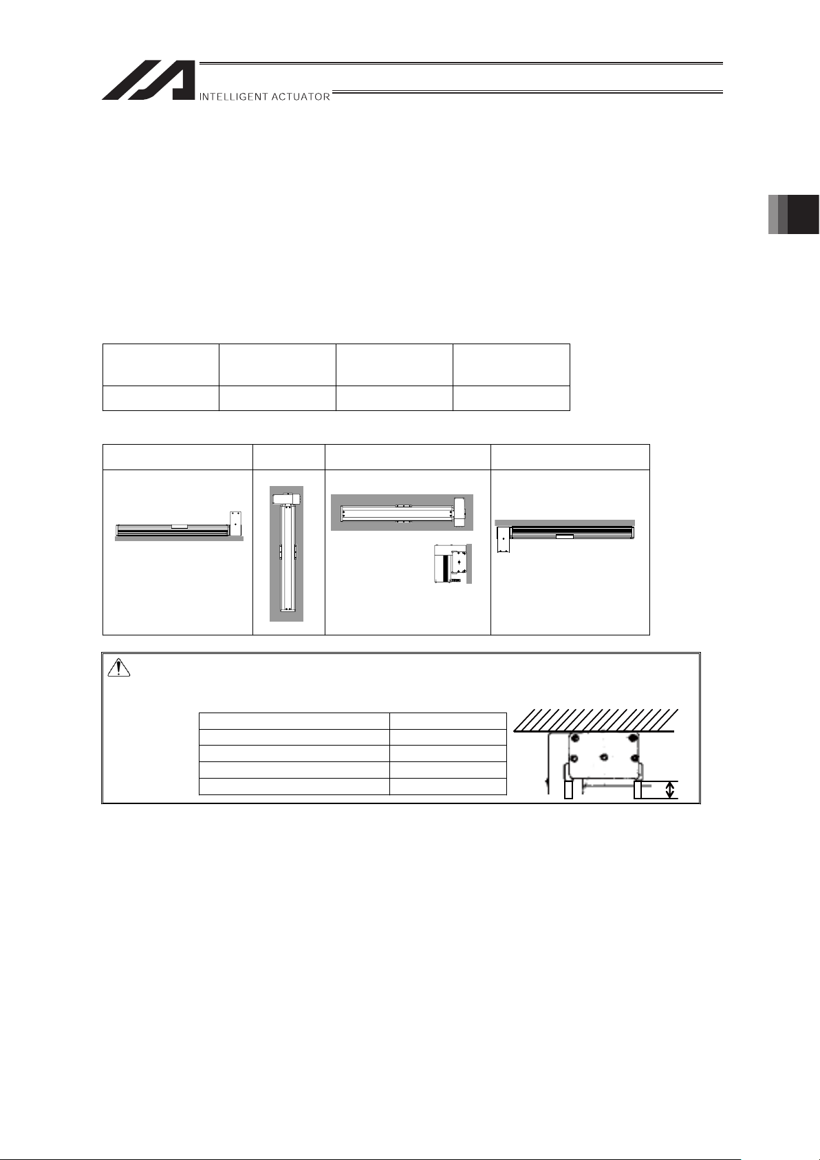
2.3.1 Orientation of the Actuator Installation
Shown below are the basic concepts for the product attachment.
Pay special attention when deciding how to install the product (
Except with custom-order
models).
{ : Available U : Precautions observing strictly × : Not available
Horizontal
installation
Vertical Mount Sideways
installation
Ceiling mount
installation
{
× ×
U
Installation orientation
Horizontal Vertical Sideways Ceiling mount
Caution: In the ceiling mount installation, the screw cover may bend, and it will be likely
to interfere with the work part. When the stroke is 900mm or more, attach the
work piece away from the surface in Distance A.
Stroke [mm] Distance A [mm]
900 or more less than 1400 5 or more
1400 or more less than 2100 10 or more
2100 or more less than 2400 15 or more
2400 or more less than 2400 20 or more
A
2. Installation
Page 36

2. Installation
30
2.3.2 Installation
[1] Installation of Main Unit
(1) Datum Surface
x The mounting table should have sufficient rigidity to avoid generating vibration.
x The surface where the actuator will be mounted should be a machined surface or that with
an accuracy equivalent to it, and the flatness should be 0.05mm or below.
x Have enough space for the maintenance work.
x The side and bottom surfaces of the base on the actuator work as the datum surfaces for
the side of the slider
x Use these surfaces as the datum surfaces for mounting.
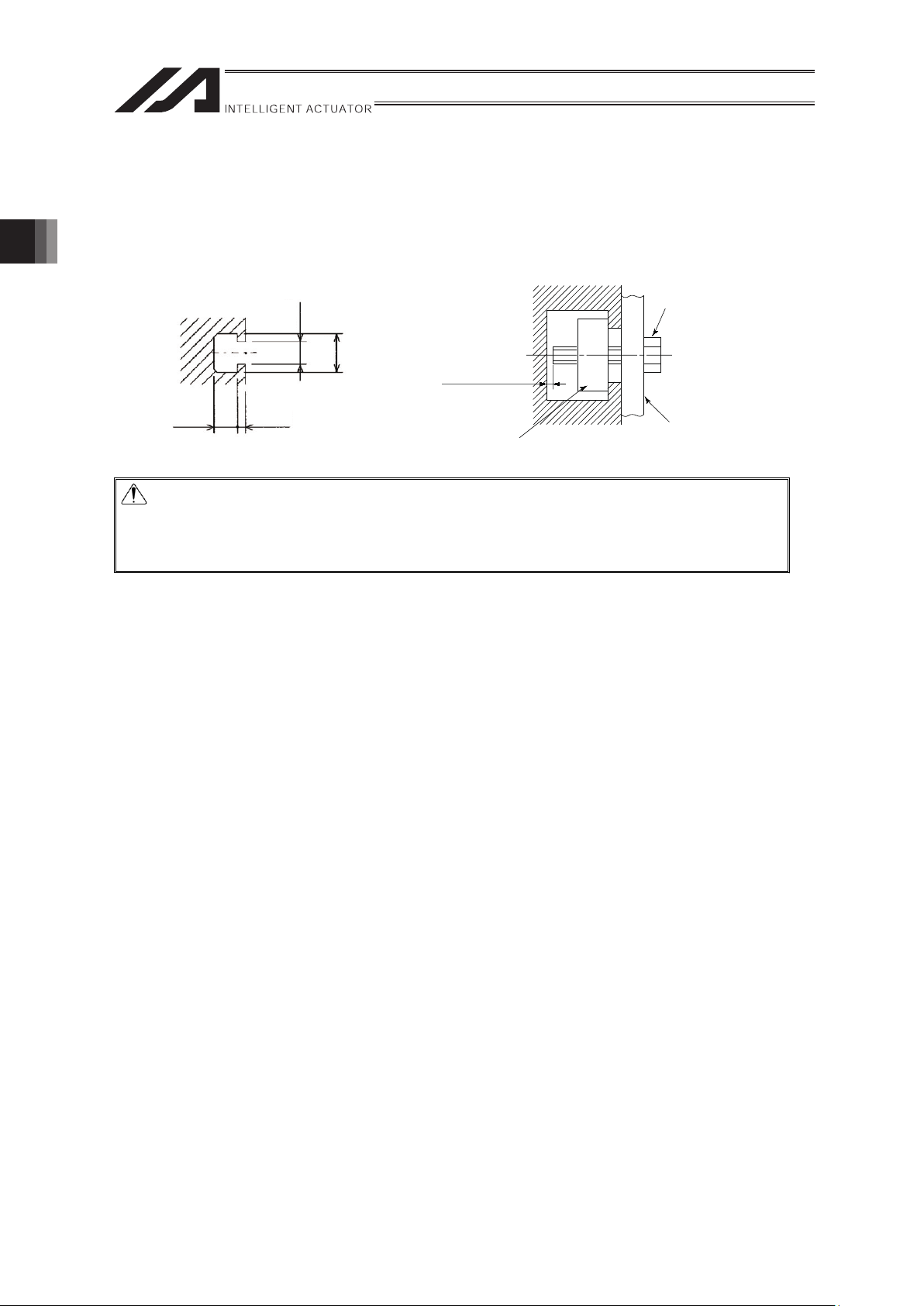
Caution: As shown in the figure above, the surfaces on the base sides are datum
surfaces for the slider movement. Utilize these faces when accuracy is
required to the operation.
Please follow the diagrams below for machining to mount on to the frame using the base
surface:
Model A Dimension [mm]
S Type 2 to 5
M Type 2 to 5
Page 37

31
(2) Mounting method
x There is a set hole on the actuator base. Fix the actuator using this set hole.
x The belt cover can be removed using the hexagon wrench with the distance to the
opposite side of 2 mm.
x For the set bolt, use hexagon socket head cap screw with the intensity classification of
10.9 or more and fasten it with the attached special washer.
Caution: Make sure to use the attached special washer. If the actuator is mounted
without using this washer, the bolt might be loosened due to the buckling on
the bolt-seated surface.
x Use a hex socket head cap screw for the attachment to the base.
x It is recommended to use high-tensile bolts with ISO-10.9 or more.
x Make sure to have the effective length of screw engagement described below or more for
the tightening of a bolt and a female screw.
x When female screw is on steel ĺ thread length same as nominal diameter
x When female screw is on aluminum ĺ thread length 2 times longer than nominal
diameter
x When using a bolt sized M8 or more and the seat for the bolt is made of aluminum, apply a
washer dedicated for high-tensile bolts (otherwise the bolt seat may sink). It is not
necessary if the bolt is M6 or smaller. Please do not apply a standard spring lock washer.
The recommended screw torque is given below.
Tightening Torque
Screw
nominal
diameter
In the case that steel is used for
the bolt seating surface:
In the case that aluminum is
used for the bolt seating surface:
M5 7.5N·m (0.77kgf·m) 4.3N·m (0.44kgf·m)
M6 12.9N·m (1.32kgf·m) 6.7N·m (0.68kgf·m)
M8 31.3N·m (3.19kgf·m) 14N·m (1.43kgf·m)
Model A B C Mounting screw
S Type 50mm 7 5mm M6
M Type 70mm 9 6mm M8
2. Installation
Page 38

2. Installation
32
[2] Load Installation
x Do not exceed the load shown in the load specification column. Please make note of the
slider moment, allowable overhang length and the load weight.
x When it is used as the Y-axis in the cantilever X-Y combination, it is easy to deform the
base itself. Therefore, use it with the Mc moment lowered to 1/2 or less of the rated value.
(Refer to table below.)
Allowable Load Moment
Model Ma Mb Mc
S Type 28.4N·m (2.9kgf·m) 40.2N·m (4.1kgf·m) 65.7N·m (6.7kgf·m)
M Type 69.6N·m (7.1kgf·m) 99.0N·m (10.1kgf·m) 161.7N·m (16.5kgf·m)
Allowable Overhang Length
Model Ma direction Mb direction Mc direction
S Type 450 or less 450 or less 450 or less
M Type 600 or less 600 or less 600 or less
x The center of gravity for the mounted object is at the halfway point of the overhang length.
Caution: When any excessive load moment is given, some influenced including
shortened guide life cycle, might be exerted. Also, when the projected length
exceeds the allowable value, vibration might be caused or adverse effect
might be caused in the guide life cycle.
Page 39

33
x There are tapped holes in the slider where you can affix the payload.
The way to affix follows the installation of the main unit.
x If you are anchoring the slider and moving the main body, attach the slider using the
tapped holes.
x The slider has two reamed holes which are used to reproduce the correct positioning
when dismounting and reattaching the slider. Also, if you require precision in your
attachment, such as a right angle, use the reamed hole to make fine adjustments.
Slider Tap Hole Diameter and Reamer Diameter
Model
Tapped
Holes
Tap depth A B C
Reamed
Hole
Reamed
Depth
S Type M6 20mm 70mm - 90mm
I6H10
10mm
M6 20mm - 70mm
M Type
M8 20mm 90mm -
120mm
I8H10
10mm
2. Installation
Page 40
34
[3] Mounting and the T-Slot (Option)
There is a T-groove on the side surface of the base provided to mount a connector box or
cable track retainer that is necessary when assembling the system.
When using the cable wiring kit for assembly, utilize the T-groove for mounting.
Use the slots as necessary to mount sensors or to anchor cables.
4.5
7.3
4.3
1.5
Space between
bolt tip
Square head nut
(or Hexagon nut)
Bolt
Mounting part
Caution : x We recommend a square nut for the T-slot but you can also use a
hexagonal nut.
x When mounting, check the bolt length to make sure the end does not touch
the bottom of the T-slot.
2. Installation
Page 41

35
3. Connection to the controller
For the controller, only the dedicated controller manufactured by our company can be used.
Use the dedicated cable enclosed in the package when connecting the actuator and the controller.
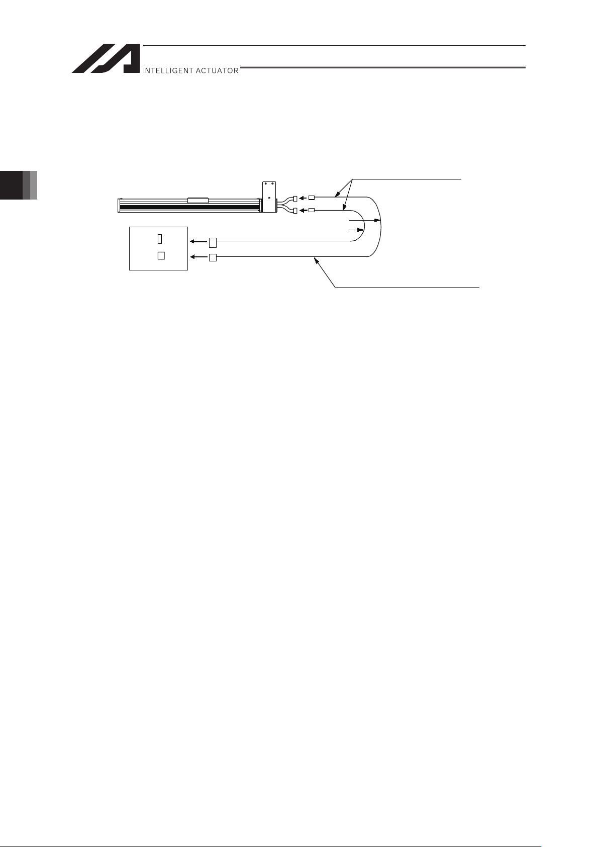
[1] Standard cable
[Connection to the XSEL-J/K controller]
Actuator
Dedicated Controller
XSEL-J/K
Dedicated Cable
(Connect actuator with
the dedicated controller)
r=51mm or more (Movable Use)
r=34mm or more (Fixed Use)
r
r
x Motor Cable CB-X-MAƑƑƑ
x Encoder Cable CB-X-PAƑƑƑ
x Limit Switch Cable CB-X-LCƑƑƑ
ƑƑƑ shows the cable length.
The max. length should be 30m.
Example) 080=8m
[Connection to the XSEL-P/Q, SSEL and SCON controller]
Actuator
Dedicated Controller
XSEL-P/Q, SSEL, SCON
r=58mm or more (Movable Use)
r=38mm or more (Fixed Use)
r
r
Dedicated Cable
(Connect actuator with
the dedicated controller)
x Motor Cable CB-X-MAƑƑƑ
x Encoder Cable CB-X1-PAƑƑƑ
x Encoder Cable with LS CB-X1-PLAƑƑƑ
ƑƑƑ shows the cable length.
The max. length should be 30m.
Example) 080=8m
3. Connection to the controller
Page 42
3. Connection to the controller
36
[2] CE Compliance Cable
[Connection to the XSEL-P/Q, SSEL and SCON controller]
Actuator
Dedicated Controller
XSEL-P/Q, SSEL, SCON
r=58mm or more (Movable Use)
r=38mm or more (Fixed Use)
r
r
Dedicated Cable
(Connect actuator with
the dedicated controller)
x Motor Cable B-XEU-MAƑƑƑ
x Encoder Cable CB-XEU1-PAƑƑƑ
x Encoder Cable with LS CB-XEU1-PLAƑƑƑ
ƑƑƑ shows the cable length.
The max. length should be 30m.
Example) 080=8m
Page 43

37
Warning : For wiring, please follow the warnings stated below. When constructing a
system as the machinery equipment, pay attention to the wiring and connection
of each cable so they are conducted properly. Not following them may cause not
only a malfunction such as cable breakage or connection failure, or an
operation error, but also electric shock or electric leakage, or may even cause a
fire.
x Use dedicated cables of IAI indicated in this instruction manual. Contact us if you wish to
have a change to the specifications of the dedicated cables.
x Make sure to turn the power off in the process of power line or cable connection or
disconnection.
x Do not attempt to cut a dedicated cable with connectors on both ends to extend, shorten or
re-joint it.
x Hold the dedicated cable to avoid mechanical force being applied to the terminals and
connectors.
x Use a cable pipe or duct to have an appropriate protection when there is a possibility of
mechanical damage on a dedicated cable.
x In case a dedicated cable is to be used at a moving part, make sure to lay out the cable
without applying any force to pull the connector or extreme bend on the cable. Do not
attempt to use the cable with a bending radius below the allowable value.
x Make certain that the connectors are plugged properly. Insufficient connection may cause
an operation error, thus it is extremely risky.
x Do not lay out the cables to where the machine runs over them.
x Pay attention to the cable layout so it would not hit peripherals during an operation. In case
it does, have an appropriate protection such as a cable track.
x When a cable is used hanging on the ceiling, prevent an environment that the cable swings
with acceleration or wind velocity.
x Make sure there is not too much friction inside the cable storage equipment.
x Do not apply radiated heat to power line or cables.
x Have a sufficient radius for bending, and avoid a bend concentrating on one point.
3. Connection to the controller
Page 44

3. Connection to the controller
38
x Do not let the cable bend, kink or twist.
x Do not pull the cable with a strong force.
x Pay attention not to concentrate the twisting force to one point on a cable.
x Do not pinch, drop a heavy object onto or cut the cable.
x When a cable is fastened to affix, make sure to have an appropriate force and do not
tighten too much.
Page 45

39
x PIO line, communication line, power and driving lines are to be put separately from each
other and do not tie them together. Arrange so that such lines are independently routed in
the duct.
x If using a cable track, make sure to use robot cables so the cables do not get twisted or
entangled inside the cable track or flexible tube, and also make the cables free to avoid
the cables getting tied. (Make sure the cables do not get pulled when being bent.)
x The occupied volume rate for the cables, etc., inside the cable track should be 60% or
less.
3. Connection to the controller
Page 46
40
4. Setting the Home Position
[1] The Principle of the Homing Operation
The Actuator performs homing in the following manner:
1) The moving direction is determined by the parameters set by the homing command.
2) It detects the mechanical end with the software in the home return operation.
3) The slider reverses direction when this end is reached and the place where the Z-phase
signal is detected becomes the reference point.
4) The slider travels further by an offset amount defined by the parameters and this position
becomes home.
[2] Fine Control of the Home Position
The number of motor revolutions from the time the slider hits the stopper to when the Z-phase
signal is generated is adjusted when the unit is shipped.
The standard value of the backing distance when the slider hits the stopper, reverses and then
stops at the home position is,
Model
Reverse distance from the mechanical end
[Approx. mm]
S Type 10
M Type 10
As long as the homing direction is the same, you can make fine adjustments to the home position
for each actuator by changing the parameters based on this value. Adjustments are made as
follows:
1) Initiate the homing operation and confirm home.
2) After that, move to the desired home position, check the difference and adjust the
parameters (For the E/G controller, any negative value is not acceptable).
3) If you allow for ample offset amount the movement range is that much more limited.
If the offset is greater than 1mm, you will have to reset the stroke soft limit.
[3] Changing the Home Direction
If you need to change the home direction after the unit is delivered, the move direction parameter
must be changed and you may need to adjust the encoder Z-phase so please contact IAI.
Also, the homing direction can not be changed by your company when it has the double slider.
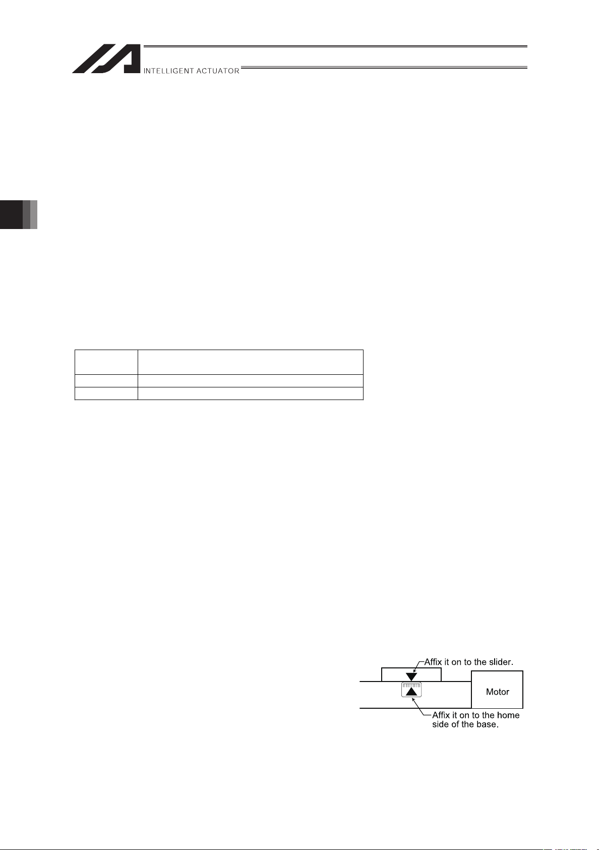
[4] Alignment Marks Affixation
Make sure to affix the alignment marks on the slider and
base so that the home position can be confirmed.
It is necessary as the reference position when the positional
deviation is confirmed because of the timing belt tooth
missing or in the case of the motor change.
4. Setting the Home Position
Page 47

41
5㧚 Maintenance inspection
5.1 Inspection Items and Inspection Schedule
Have maintenance inspections following the intervals below.
8 hours per day is assumed as operation condition
Have inspections more frequently if the operation frequency is high for night and day continuous
operation, etc.
Visual inspection Internal Check
Grease supply
*1
At startup
inspection
{
1 month after start
of operation
{
6 months after start
of operation
{ {
1 year after start of
operation
{ { {
Every 6 months
thereafter
{
Every year
thereafter
{ { {
*1 If the actuator is operated back and forth repeatedly over a distance of 30 mm or less, the oil film created
by the grease may be broken. It is recommended to have 5 cycles of back and forth operation in a distance
more than 50mm after every 5,000 to 10,000 rounds of the short distance operation. A layer of the grease
will recover.
5.2 Visual inspection
Conduct he item below in the visual inspection.
Main Body Looseness of attachment screws
Cables Scratches, proper connection of
connectors
Overall Vibration, Abnormal noise
5.3 Cleaning
x Please clean the external body on a regular basis.
x When cleaning, wipe with a soft cloth to remove dust and dirt.
x Do not blow compressed air so dust would not get in from gaps.
x Do not apply petroleum solvent since it may damage the resin or painted surfaces.
x When extremely dirty, wipe it off firmly with cloth that a neutral detergent or alcohol is applied
on.
5. Maintenance inspection
Page 48

5. Maintenance inspection
42
5.4 Internal Inspection
Turn the power OFF. Remove the belt cover and pulley cover, and visually inspect the interior.
Conduct he item below in the internal inspection.
Main Body Looseness of attachment screws
Guide Part Condition and dirt of lubricant
Timing Belt
Driving Belt : Scratch and tension
confirmation
Deceleration Belt : Scratch and tension
confirmation
Rear Side of the
Belt Cover
Condition of lubricant
The Belt cover can be detached with a 2mm-sized hex wrench and the pulley cover with a
2mm-sized or 1.5mm-sized hex wrench.
Visually inspect the inside condition. In the inspection, it should be checked if dust is involved
inside and the condition of the lubricant.
Even if the grease looks brown, it will be fine as long as the sliding area seems wet and shiny.
When the grease looks dirty and dull due to dust or wear due to the use for a long time, replenish
grease after cleaning.
Refer to Item 5.7 Check Items for the timing belt check.
x Grease Check on the Rear Side of the Belt Cover
Check the lubricating condition on the rear side of the belt cover and belt cover support (made
of resin) located at the center of the slider so that the frictional resistance between the slider
and belt cover is reduced to move the slider smoothly.
When there is too little grease, replenish it.
Grease to be used: Multemp LRL 3 manufactured by Kyodo Yushi or equivalent
5.5 Internal Cleanup
x When cleaning, wipe with a soft cloth to remove dust and dirt.
x Do not blow compressed air so dust would not get in from gaps.
x Do not use petroleum-based solvents, neutral detergents or alcohol.
Page 49

43
5.6 Grease Supply
(1) Applied Grease
Use lithium grease no. 2.
The following grease is applied when the product is shipped out from IAI factory.
Guide Idemitsu Kosan Daphne Eponex Grease No. 2
Apart from above, there are equivalent sorts of grease sold in the market. For details contact a
grease supplier, provide the grease name shown above and ask them to select an equivalent.
Listed below are some equivalents for an example.
Showa Shell Sekiyu K. K. Alvania Grease No.2
Mobil Oil Mobilux 2
Warning: Do not attempt to apply fluorine grease. When mixed with lithium grease, not only
decrease the grease characteristics, but also may damage the actuator.
(2) Grease Supply
Use the two grease nipples on the slider end area for lubrication.
Grease is replenished with the belt cover removed.
1) Squirt the grease from the grease nipple using a grease gun (Please see drawing below).
2) Also, inject the grease into the other grease hole (Inject both the left and right holes).
3) Move the slider back and forth several times by hand.
4) Repeat the lubrication one more time.
5) Wipe off the excessive grease.
Caution: In case the grease got into your eye, immediately go see the doctor to get
appropriate care. After finishing the grease supply work, wash your hands
carefully with water and soap to rinse the grease off.
Grease Nipple
5. Maintenance inspection
Page 50

5. Maintenance inspection
44
5.7 How to Inspect the Timing Belt
Visual inspection is done by removing the belt cover and pulley cover. Since the timing belt wear
largely depends on the operational requirements, as a rule, replacement period can not be
determined. Generally speaking, the life span of the timing belt is the life span of a couple hundred
thousand revolutions. As an actual replacement period standard, the timing belt is replaced when
the following symptoms are confirmed.
When belt replacement is necessary, please contact our technical service department or sales
representative (due to detailed specification differences, please always contact IAI when replacing
the timing belt).
x When the gear and belt area show obvious friction.
x When swelling occurs as a result of oil adhesion.
x When damages such as a crack occurs on the belt gear and back side.
x When the belt breaks.
When installing an actuator, ensure as much working space as it can be secured to perform a
work to remove the screws holding the pulley cover and to remove the belt cover so the timing belt
can be inspected and adjusted.
The table below shows the types of timing belt that we use.
Model Belt-Drive Type Timing Belt Supplier
S Type S3M, 18-wide S3M24, 15-wide Bandoh Kagaku, Inc.
M Type S5M, 25-wide S3M339, 20-wide Bandoh Kagaku, Inc.
Page 51

45
5.7.1 Belt Tension Adjustment Method
Since inadequate belt tension will lead to location drift due to gear skipping, noise occurrence as
well as cause the motor to breakdown, proper tension adjustment is required.
[How to Adjust the Timing Belt:]
Remove the pulley cover, loosen the 4 tension adjustment bolts and lift the motor cover up to place
the appropriate axis load onto the belt, and tighten the 4 tension adjustment bolts (see chart
below).
For the tension loads, comply with the standards below.
Model Axis load : A
S Type 5kgf
M Type 10kgf
5. Maintenance inspection
Page 52

5. Maintenance inspection
46
[How to Adjust the Driver Belt Tension:]
Driver belt tension adjustment is done using the front cover adjustment bolt.
Since the adjustment bolt is fixed using the hexagonal nut, when adjusting, loosen the hexagonal
nut, then adjust the adjustment bolt as is. Upon adjustment, tighten the hexagonal nut once again.
Front cover
Hexagonal nut
(For loosening prevention:
Use of 8 mm Spanner Wrench)
Screw for driver belt tension adjustment
(Use of Hexagon Wrench with the
Distance to the Opposite Side of 4 mm)
Belt
LL
δ
F
LL
Because the deflection varies depending on the stroke, calculate the deflection G using the
following formula.
Model Flexible load : F
Flexure : G
S Type 0.8kgf±10%
M Type 1.8kgf±5%
G= 0.032L
Page 53

47
5.8 How to Replace the Timing Belt
[Items Required for Replacement Work]
x Replacement Driving Belt
x Packing Tape
x 8 mm Spanner Wrench
x Hexagon Wrench Set
x Push-Pull Gauge and Square
x Personal Computer or Teaching Pendant
x Tension Gauge (Tension of 10 kgf or more available)
x Strong Thread (or Long Harness Belt)
[Replacement Operation Outline]
1) Loosen the tension adjusting bolt and replace the belt. Then, tighten the adjusting bolt until
the specified tension value is reached.
2) Perform the homing operation.
Loosen the deceleration belt and then, move the slider to the mechanism end and fix it. Then,
fix the motor shaft at the position about 90 degrees deviated from the counter mark and
adjust the deceleration belt to reach the specified tension value.
3) Perform the homing operation using the personal computer or teaching pendant and confirm
the deviation from the original home position. If there is any deviation, adjust it using the
home offset value in the parameters.
(Note) For the home offset for E/G controller, any negative value can not be entered.
Therefore, deviate the position slightly less than 90 degrees.
[Procedure]
1) Confirm the motor shaft rotating direction when the slider is moved from the home position to
the mechanism end.
(The rotating direction varies depending on the motor installation position. Therefore, the
confirmation is always required).
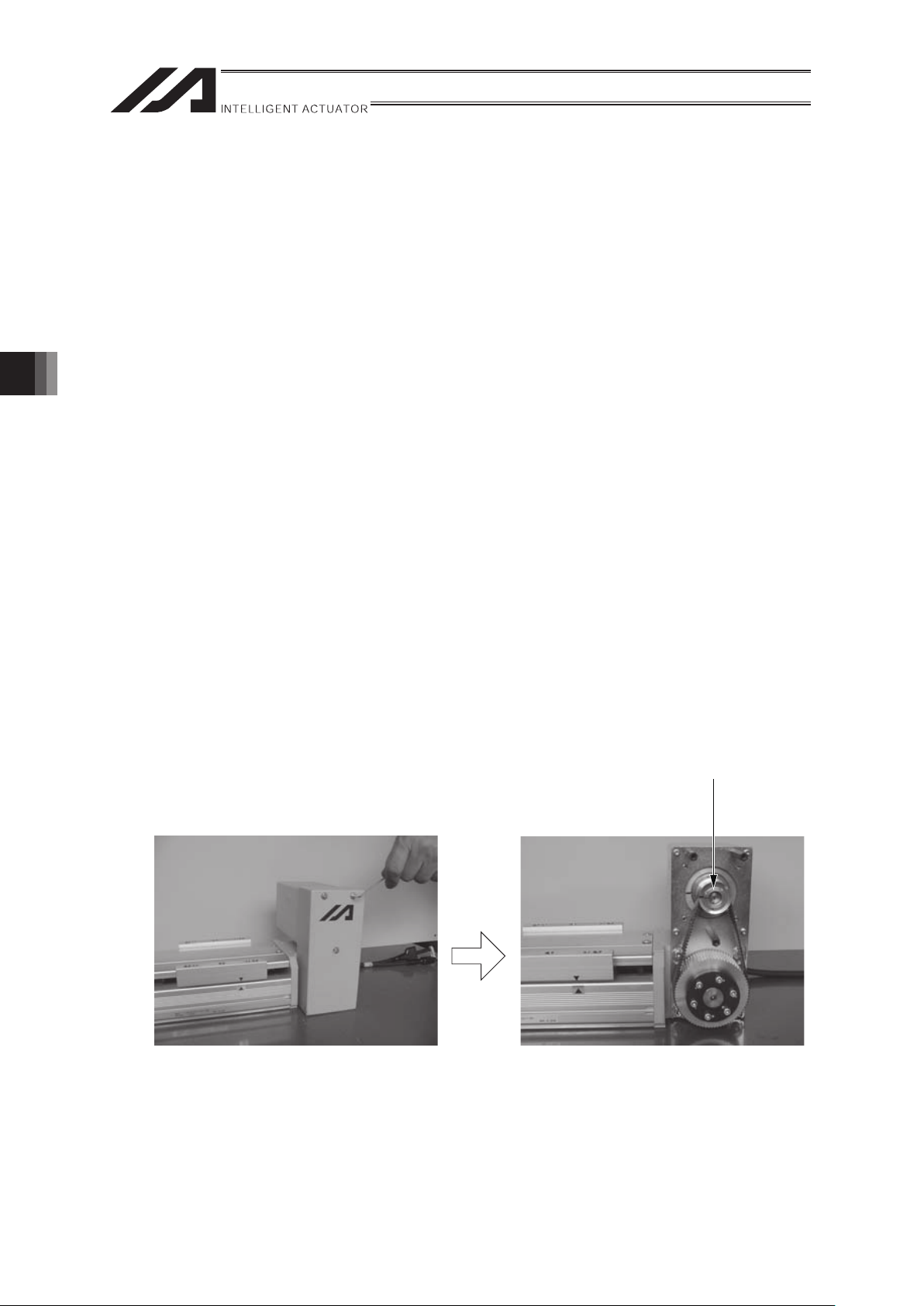
• Remove the pulley cover.
(Use a hexagon wrench with the distance to the
opposite side of 1.5 mm for IF-S or 2 mm for IF-M).
• Confirm the motor shaft rotating direction.
5. Maintenance inspection
Page 54
5. Maintenance inspection
48
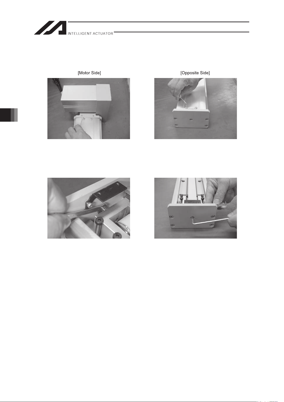
2) Remove the belt cover.
Remove the machine set screw (4 locations) on the motor side and also the opposite side.
(Use a hexagon wrench with the distance to the opposite side of 2 mm).
3) Loosen the belt tension until the pulley is turned without making contact.
• Fix the hexagon nut using the 8 mm
spanner wrench.
• Loosen the adjusting bolt.
(Use a hexagon wrench with the distance
to the opposite side of 4 mm)
Page 55

49
4) Remove the belt holding plate (2 locations). (Use a hexagon wrench with the distance to the
opposite side of 3 mm for IF-3 or 4 mm for IF-M).
5. Maintenance inspection
Page 56
5. Maintenance inspection
50
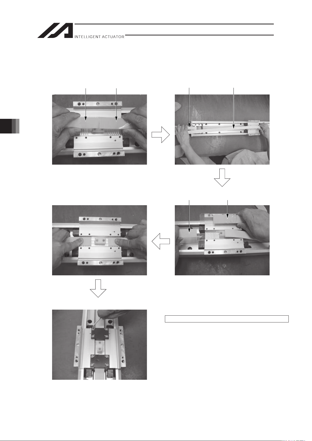
5) Replace the belt.
• Connect the replacement belt to the
current belt using the packing tape.
Replacement Belt
• Pull out the current belt.
Current Belt Replacement BeltCurrent Belt
• Align the both ends of the replacement
belts with the attachment teeth.
(Confirm that they are aligned perfectly).
• Separate the replacement belt from the
current belt.
• Attach the belt holding plate (2 locations).
Tightening Torque: 20 kgf for IF-S and 45 kgf for IF-M
Page 57

51
6) Adjust the belt tension until the specified tension value is reached.
• Move the slider to the mechanism end on the motor side.
Measure the distance from the slider side to the pulley center and mark the central position.
Measure this distance and find the central position.
• Press the push-pull gauge against the central position and tighten the adjusting bolt so
that the specified values for the deflection load and deflection are reached. (Refer to
“How to Adjust the Driver Belt Tension” for the specified values).
• Tighten the hexagon nut securely.
7) Attach the belt cover.
5. Maintenance inspection
Page 58

5. Maintenance inspection
52
8) Adjust it to recover the home position.
• Remove the pulley cover and loosen the bolt fixing the motor bracket using the
hexagon wrenches with the distance to the opposite side of 3 mm and 4 mm.
Then, slide the motor belt until the pulley is turned without making any contact.
Use of Hexagon Wrench with the
Distance to the Opposite Side of 3 mm
Use of Hexagon Wrench with the
Distance to the Opposite Side of 4 mm
• Turn the motor shaft at an angle of 90 degrees from the counter mark to the
returning direction to the mechanism end (direction confirmed at first).
Example:
In the case of X-SEL controller, turn it at
an angle of 90 degrees to the returning
direction to the mechanism end.
(Example in the case of turning right)
First Counter Mark Position
Controller
X-SEL
P-Driver
SEL-E/G
SEL-ES/GS,F,H
E-Con 90°
45°
102°
Returning Amount from
the Counter Mark
• Go the ring-shaped strong thread (or long
harness belt) around the motor cover and
pull it using the tension gauge.
• Pull it with the specified tension and tighten
the bolt (At that time, take care so that the
slider or motor shaft does not move).
Tension: 5 kgf for IF-S and 10 kgf for IF-M
Page 59

53
9) Attach the pulley cover.
10) Turn on the power to the controller and perform the homing operation from the personal
computer or teaching pendant.
(In the case that the absolute encoder has been mounted, the absolute reset is required).
Confirm the deviation from the original home position.
If there is any deviation, adjust it using the home offset value in the parameters.
5. Maintenance inspection
Page 60
5. Maintenance inspection
54
5.9 Deceleration Belt Replacement
[Items Required for Replacement Work]
x Replacement Deceleration Belt
x Hexagon Wrench Set
x Personal Computer or Teaching Pendant
x Tension Gauge (Tension of 10 kgf or more available)
x Ring-shaped Strong Thread (or Long Harness Belt)
[Replacement Operation Outline]
1) Loosen the bolt fixing the motor bracket and replace the belt.
2) Perform the homing operation.
Move the slider to the mechanism end and fix it. At the same time, fix the motor shaft at the
position about 90 degrees deviated from the counter mark and adjust the deceleration belt to
reach the specified tension value.
3) Perform the homing operation using the personal computer or teaching pendant and confirm
the deviation from the original home position. If there is any deviation, adjust it using the
home offset value in the parameters.
(Note) For the home offset for E/G controller, any negative value can not be entered.
Therefore, deviate the position slightly less than 45 degrees.
[Procedure]
1) Confirm the motor shaft rotating direction when the slider is moved from the home position
to the mechanism end.
(The rotating direction varies depending on the motor installation position. Therefore, the
confirmation is always required).
• Remove the pulley cover. • Confirm the motor shaft rotating direction.
(Use a hexagon wrench with the
distance to the opposite side of 1.5 mm
for IF-S or 2 mm for IF-M).
Page 61
55
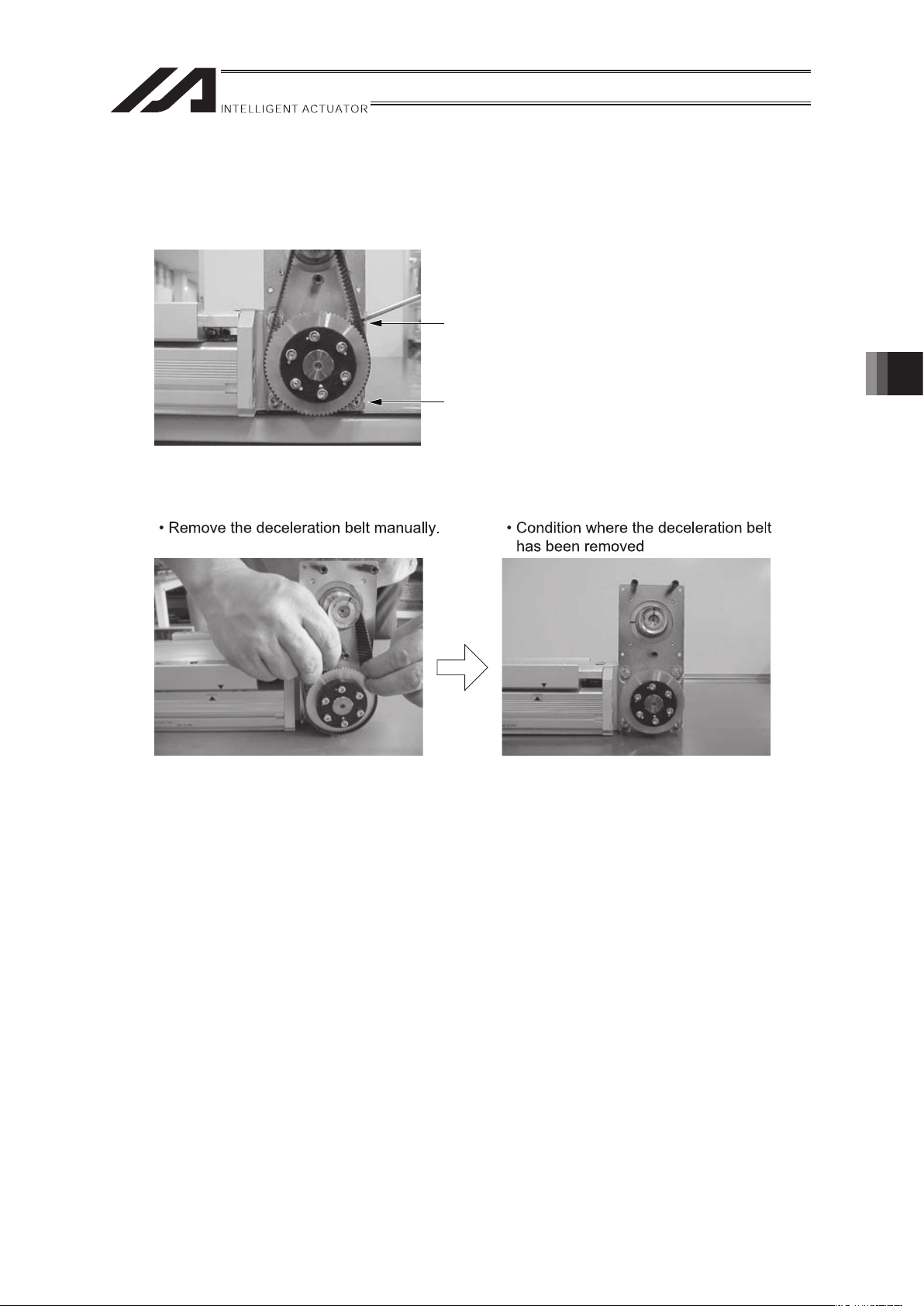
2) Loosen the deceleration belt.
Loosen the bolt fixing the motor bracket using the hexagon wrenches with the distance to
the opposite side of 3 mm and 4 mm. Then, slide the belt until the pulley is turned without
making any contact.
Use of Hexagon Wrench with the
Distance to the Opposite Side of 3 mm
Use of Hexagon Wrench with the
Distance to the Opposite Side of 4 mm
3) Remove the deceleration belt.
4) Attach the new deceleration belt manually.
5. Maintenance inspection
Page 62

5. Maintenance inspection
56
5) Adjust it to recover the home position.
6) Adjust the belt tension.
• Go the ring-shaped strong thread (or long
harness belt) around the motor cover and
pull it using the tension gauge.
• Pull it with the specified tension and tighten
the bolt. (At that time, take care so that the
slider or motor shaft does not move).
Tension: 5 kgf for IF-S and 10 kgf for IF-M
7) Attach the pulley cover.
8) Turn on the power to the controller and perform the homing operation from the personal
computer or teaching pendant.
(In the case that the absolute encoder has been mounted, the absolute reset is required).
Confirm the deviation from the original home position. If there is any deviation, adjust it using
the home offset value in the parameters.
Page 63

57
5.10 Motor Replacement Process
[Items Required for Replacement Work]
x Motor for Replacemen (Refer to the right picture).
(Confirm that the counter mark is attached).
x Personal Computer or Teaching Pendant
x Tension Gauge (Tension of 10 kgf or more available)
x Strong Thread (or Long Harness Belt)
x Hexagon Wrench Set
x 5.5 mm Spanner Wrench and
Phillips Type Screwdriver
[Replacement Operation Outline]
1) Remove the deceleration belt and replace the motor.
2) Perform the homing operation.
Press the slider against the mechanism end on the home position side and fix it. Then, fix
the motor shaft at the position deviated the specified amount from the counter mark position.
3) Attach the deceleration belt and tighten the motor bracket set bolt so that the specified
tension value is reached.
4) Perform the homing operation using the personal computer or teaching pendant and confirm
the deviation from the original home position.
If there is any deviation, adjust it using the home offset value in the parameters.
(Note) For the home offset for E/G controller, any negative value can not be entered. Therefore, deviate
the position slightly less than 45 degrees.
Mechanism End
Subject controller
X-SEL/E-Con/P-Driver
SEL-E/G
SEL-ES/GS,F,H
About 9 mm
1mm
Corresponding to the motor
angle of 90 degrees
About 4.4 mm
5.6mm
Corresponding to the motor
angle of 45 degrees
About 10 mm
Corresponding to the motor
angle of 102 degrees
Set based on the home offset in the parameters
(Above value is set when the product is shipped from the factory).
At this position, the motor counter mark is aligned.
A
t this position, the motor counter mark is aligned.
Home Position Z-phase ON position
5. Maintenance inspection
Page 64

5. Maintenance inspection
58
[Procedure]
1) Confirm the motor shaft rotating direction when the slider is moved from the home position
to the mechanism end.
(The rotating direction varies depending on the motor installation position. Therefore, the
confirmation is always required).
• Remove the pulley cover.
(Use a hexagon wrench with the distance
to the opposite side of 1.5 mm for IF-S or
2 mm for IF-M).
• Confirm the motor shaft rotating direction.
2) Remove the cable protection cover and disconnect the motor connector, encoder connector
and motor earth cable.
• Protection Cover Removal
(Use a hexagon wrench with the distance
to the opposite side of 1.5 mm)
• Because the earth cable is tightened with the
M3 bolt, the 5.5 mm spanner wrench and
Phillips type screwdriver are used.
3) Remove the motor cover.
(Use a hexagon wrench with the
distance to the opposite side of 2.5 mm)
4) Slightly loosen the bolt fixing the motor.
(Use a hexagon wrench with the distance to
the opposite side of 3 mm for IF-S or 4 mm
for IF-M).
Page 65

59
5) Loosen the bolt fixing the motor bracket using the hexagon wrenches with the distance to
the opposite side of 3 mm and 4 mm). Then, slide the belt.
Then, the deceleration belt tension is loosened. Remove the deceleration belt from the
pulley on the actuator side.
6) Remove the motor.
5. Maintenance inspection
Page 66

60
7) Attach the new motor.
Then, turn the motor shaft specified amount to the returning direction to the mechanism end
(direction confirmed at the beginning) from the counter mark.
8) Attach the deceleration belt.
Press the slider against the mechanism end and fix it. Then, taking care so that the motor
shaft does not move (refer to the above picture), put the bet on the pulley on the motor side,
and then on the opposite side.
When it is difficult to put the belt, loosen the motor set bolt.
In this case, after the belt is attached, make sure to tighten the motor set bolt securely.
9) Pull the deceleration belt with the specified tension and tighten the motor bracket set bolt.
• Go the ring-shaped strong thread (or long
harness belt) around the motor cover and
pull it using the tension gauge.
• Pull it with the specified tension and tighten the
bolt. (At that time, take care so that the slider or
motor shaft does not move).
Tension: 5 kgf for IF-S and 10 kgf for IF-M
5. Maintenance inspection
Page 67

61
6. External Dimensions
6.1 IF-SA-60
Stroke 200 300 400 500 600 700 800 900 1000 1100 1200 1300 1400 1500 1600 1700 1800 1900 2000
A 516 616 716 816 916 1016 1116 1216 1316 1416 1516 1616 1716 1816 1916 2016 2116 2216 2316
B 429 529 629 729 829 929 1029 1129 1229 1329 1429 1529 1629 1729 1829 1929 2029 2129 2229
C 200 300 400 500 600 700 800 900 1000 1100 1200 1300 1400 1500 1600 1700 1800 1900 2000
D 1 1 2 2 3 3 4 4 5 5 6 6 7 7 8 8 9 9 10
E 67 167 67 167 67 167 67 167 67 167 67 167 67 167 67 167 67 167 67
F 8 8 10 10 12 12 14 14 16 16 18 18 20 20 22 22 24 24 26
Weight [kg] 4.4 4.9 5.4 5.9 6.4 6.8 7.3 7.8 8.3 8.8 9.2 9.7 10.2 10.7 11.2 11.6 12.1 12.6 13.1
6. External Dimensions
Page 68

6. External Dimensions
62
6.2 IF-SA-100
Stroke 200 300 400 500 600 700 800 900 1000 1100 1200 1300 1400 1500 1600 1700 1800 1900 2000
A 516 616 716 816 916 1016 1116 1216 1316 1416 1516 1616 1716 1816 1916 2016 2116 2216 2316
B 429 529 629 729 829 929 1029 1129 1229 1329 1429 1529 1629 1729 1829 1929 2029 2129 2229
C 200 300 400 500 600 700 800 900 1000 1100 1200 1300 1400 1500 1600 1700 1800 1900 2000
D 1 1 2 2 3 3 4 4 5 5 6 6 7 7 8 8 9 9 10
E 67 167 67 167 67 167 67 167 67 167 67 167 67 167 67 167 67 167 67
F 8 8 10 10 12 12 14 14 16 16 18 18 20 20 22 22 24 24 26
Weight [kg] 4.6 5.1 5.6 6.1 6.6 7.0 7.5 8.0 8.5 9.0 9.4 9.9 10.4 10.9 11.4 11.8 12.3 12.8 13.3
Page 69

63
6.3 IF-MA-200
Stroke
200 300 400 500 600 700 800 900 1000 1100 1200 1300 1400 1500 1600 1700 1800 1900 2000 2100 2200 2300 2400 2500
A 578 678 778 878 978 1078 1178 1278 1378 1478 1578 1678 1778 1878 1978 2078 2178 2278 2378 2478 2578 2678 2778 2878
B 473 573 673 773 873 973 1073 1173 1273 1373 1473 1573 1673 1773 1873 1973 2073 2173 2273 2373 2473 2573 2673 2773
C 200 300 400 500 600 700 800 900 1000 1100 1200 1300 1400 1500 1600 1700 1800 1900 2000 2100 2200 2300 2400 2500
D 1 1 2 2 3 3 4 4 5 5 6 6 7 7 8 8 9 9 10 10 11 11 12 12
E 111 211 111 211 111 211 111 211 111 211 111 211 111 211 111 211 111 211 111 211 111 211 111 211
F 8 8 10 10 12 12 14 14 16 16 18 18 20 20 22 22 24 24 26 26 28 28 30 30
Weight
[kg]
7.7 8.5 9.3 10.0 10.8 11.6 12.4 13.2 14.0 14.8 15.6 16.4 17.2 17.9 18.7 19.5 20.3 21.1 21.9 22.7 23.5 24.3 25.1 25.8
6. External Dimensions
Page 70

64
6.4 IF-MA-400
Stroke
2003004005006007008009001000 1100 1200 1300 1400 1500 1600 1700 1800 1900200021002200 2300 2400 2500
A
5786787788789781078117812781378 1478 1578 1678 1778 1878 1978 2078 2178 2278237824782578 2678 2778 2878
B
473573673773873973107311731273 1373 1473 1573 1673 1773 1873 1973 2073 2173227323732473 2573 2673 2773
C
2003004005006007008009001000 1100 1200 1300 1400 1500 1600 1700 1800 1900200021002200 2300 2400 2500
D
112233445 5 6 6 7 7 8 8 9 9101011 11 12 12
E
111211111211111211111211111 211 111 211 111 211 111 211 111 211111211111 211 111 211
F
8810101212141416 16 18 18 20 20 22 22 24 24262628 28 30 30
Weight
[kg]
8.29.09.810.511.312.112.913.714.5 15.3 16.1 16.9 17.7 18.4 19.2 20.0 20.8 21.622.423.224.0 24.8 25.6 26.3
6. External Dimensions
Page 71

65
7. Life
The product life is 10,000km (reference) when operating the actuator with the maximum allowable
load moment.
7. Life
Page 72

8. Warranty
66
8. Warranty
8.1 Warranty Period
One of the following periods, whichever is shorter:
x 18 months after shipment from our factory
x 12 months after delivery to a specified location
x 2,500 operational hours
8.2 Scope of the Warranty
Our products are covered by warranty when all of the following conditions are met. Faulty products
covered by warranty will be replaced or repaired free of charge:
(1) The breakdown or problem in question pertains to our product as delivered by us or our
authorized dealer.
(2) The breakdown or problem in question occurred during the warranty period.
(3) The breakdown or problem in question occurred while the product was in use for an
appropriate purpose under the conditions and environment of use specified in the instruction
manual and catalog.
(4) The breakdown of problem in question was caused by a specification defect or problem, or by
a quality issue with our product.
Note that breakdowns due to any of the following reasons are excluded from the scope of
warranty:
1) Anything other than our product
2) Modification or repair performed by a party other than us (unless we have approved such
modification or repair)
3) Anything that could not be easily predicted with the level of science and technology
available at the time of shipment from our company
4) A natural disaster, man-made disaster, incident or accident for which we are not liable
5) Natural fading of paint or other symptoms of aging
6) Wear, depletion or other expected result of use
7) Operation noise, vibration or other subjective sensation not affecting function or
maintenance
Note that the warranty only covers our product as delivered and that any secondary loss arising
from a breakdown of our product is excluded from the scope of warranty.
8.3 Honoring the Warranty
As a rule, the product must be brought to us for repair under warranty.
Page 73

67
8.4 Limit in Responsibility
(1) We shall assume no liability for any special damage, consequential loss or passive loss such
as a loss of expected profit arising from or in connection with our product.
(2) We shall not be liable for any program or control method created by the customer to operate
our product or for the result of such program or control method.
8.5 Conditions of Conformance with Applicable Standards/Regulations, Etc., and Applications
(1) If our product is combined with another product or any system, device, etc., used by the
customer, the customer must first check the applicable standards, regulations and/or rules.
The customer is also responsible for confirming that such combination with our product
conforms to the applicable standards, etc. In such a case we will not be liable for the
conformance of our product with the applicable standards, etc.
(2) Our product is for general industrial use. It is not intended or designed for the applications
specified below, which require a high level of safety. Accordingly, as a rule our product cannot
be used in these applications. Contact us if you must use our product for any of these
applications:
1) Medical equipment used to maintain, control or otherwise affect human life or physical
health
2) Mechanisms and machinery designed for the purpose of moving or transporting people
(For vehicle, railway facility or air navigation facility)
3) Important safety parts of machinery (Safety device, etc.)
4) Equipment used to handle cultural assets, art or other irreplaceable items
(3) Contact us at the earliest opportunity if our product is to be used in any condition or
environment that differs from what is specified in the catalog or instruction manual.
8.6 Other Items Excluded from Warranty
The price of the product does not include the cost to create programs or sending an engineer.
Accordingly, a separate fee will be charged in the following cases even during the warranty period:
1) Instruction for adjustment in installation or joining to the test run of product operation.
2) Maintenance inspection
3) Technical instruction or education for operation or cable layout
4) Technical instruction or education related to programing such as creating a program
8. Warranty
Page 74

68
Change History
Revision Date Description of Revision
2012.01
2012.07
2012.12
Ninth Edition
Page 7 Note of available and not available added to attachment
orientation
Tenth Edition
Whole manual layout has been revised and corrected
Eleventh Edition
Page 46 G= 0.0032L ĺ G= 0.032L
Change History
Page 75

Page 76

Manual No.: ME3618-11A (December 2012)
The information contained in this document is subject to change without notice for purposes of
product improvement.
Copyright © 2012. Dce. IAI Corporation. All rights reserved.
12.12.000
Head Office: 577-1 Obane Shimizu-KU Shizuoka City Shizuoka 424-0103, Japan
TEL +81-54-364-5105 FAX +81-54-364-2589
website: www.iai-robot.co.jp/
Ober der Röth 4, D-65824 Schwalbach am Taunus, Germany
TEL 06196-88950 FAX 06196-889524
SHANGHAI JIAHUA BUSINESS CENTER A8-303, 808, Hongqiao Rd. Shanghai 200030, China
TEL 021-6448-4753 FAX 021-6448-3992
website: www.iai-robot.com
Technical Support available in USA, Europe and China
Head Office: 2690 W. 237th Street, Torrance, CA 90505
TEL (310) 891-6015 FAX (310) 891-0815
Chicago Office: 1261 Hamilton Parkway, Itasca, IL 60143
TEL (630) 467-9900 FAX (630) 467-9912
TEL (678) 354-9470 FAX (678) 354-9471
website: www.intelligentactuator.com
Atlanta Office: 1220 Kennestone Circle, Suite 108, Marietta, GA 30066
 Loading...