

Page 1

X-SEL
IX Series
Teaching Pendant
Instruction Manual
IAI Corporation
Ver. 2.0
Page 2

1. Introduction .........................................................................................................1
2. Before Use..........................................................................................................1
3. Safety Precautions..............................................................................................2
4. Warranty Term and Coverage.............................................................................3
5. Connection to Controller .....................................................................................4
6. Functions and Specifications of Teaching Pendant.............................................6
6-1. Main operation keys and their functions
.........................................................6
7. Mode Flow Chart.................................................................................................9
8. Data Storage Method........................................................................................14
8-1. Factory setting: When system memory backup battery is used............................14
8-2. When system memory backup battery is not used...............................................15
8-3. Cautions...............................................................................................................16
9. Simple Operating Procedures...........................................................................17
9-1. Creation of position data.......................................................................................18
9-2. Creation of program..............................................................................................25
9-3. Change of application program ............................................................................35
10. Program Execution............................................................................................40
10-1. Operation check ...................................................................................................40
10-2. Setting of break point............................................................................................42
10-3. Monitor while in running........................................................................................42
11. Position Editing .................................................................................................45
11-1. Mdi (numeric input)...............................................................................................45
11-2. Teac (teaching).....................................................................................................46
11-3. Jog movement direction and coordinate system ..................................................49
11-4. Actuator operation................................................................................................54
11-5. Teaching input example........................................................................................65
11-6. Copy and movement of position data...................................................................71
11-7. Deletion of position data.......................................................................................72
12. Program Editing ................................................................................................73
12-1. Program input method..........................................................................................73
12-2. Symbol input during program editing....................................................................78
12-3. One-line comment input .......................................................................................80
12-4. Copy and movement of program.......................................................................... 82
12-5. Deletion of program..............................................................................................83
12-6. Flash ROM writing................................................................................................ 85
Page 3

13. Coordinate System Data Editing.......................................................................86
13-1. Editing of work coordinate system data................................................................87
13-2. Editing of tool coordinate ststem data...................................................................90
13-3. Editing of simple interference check zone............................................................93
14. Symbol Editing..................................................................................................98
14-1. Symbol editing item s ............................................................................................98
14-2. Input example: Symbolization of local integer variables.......................................99
14-3. Symbol edit screen for each item.......................................................................103
14-4. Flash ROM writing..............................................................................................107
15. Parameter Editing ...........................................................................................
15-1. Parameter editing items......................................................................................108
15-2. Input example: Editing of axis-specific parameters.............................................109
16. Monitoring .......................................................................................................
16-1. Monitor items......................................................................................................112
16-2. Input ports ..........................................................................................................113
16-3. Output ports........................................................................................................113
16-4. Global flags ........................................................................................................113
16-5. Global variables..................................................................................................114
16-6. Axis status..........................................................................................................115
16-7. System status.....................................................................................................119
16-8. Error detail information.......................................................................................122
16-9. Version information.............................................................................................123
17. Controller ........................................................................................................
17-1. Controller items ..................................................................................................124
17-2. Flash ROM writing..............................................................................................125
17-3. Software reset ....................................................................................................126
17-4. Error reset ..........................................................................................................126
17-5. Memory clear......................................................................................................127
17-6. Reconnection .....................................................................................................127
17-7. Baud rate change ...............................................................................................128
17-8. Safety velocity ....................................................................................................128
17-9. Driving power recovery request..........................................................................129
17-10. Action restart request .........................................................................................129
17-11. Driving power recovery request (RPwr) and action restart request (RAct).........130
17-12. Absolute reset ....................................................................................................131
108
112
124
APPENDIX ..............................................................................................................
Error Level Control............................................................................................................143
X-SEL Teaching Pendant Error List (Application Part)......................................................144
X-SEL Teaching Pendant Error List (Core Part )................................................................147
143
Page 4

1. Introduction
Thank you very much for purchasing our X-SEL Controller Tea ching Pendant. Improper usage
or mishandling may result in a product not only being unable to deliver full functions but also
produce unexpected troubles or shorten the product’s life. Please read this Manual carefully, and
operate the product properly by paying attention to its handling. When operating the Teaching
Pendant, always keep this Manual on hand and read the relevant items as required.
For the actuator and controller to be used, be sure to refer to the Instruction Manuals attached
to the products.
▪ While the Teaching Pendant is left connected, “Effect” is valid for the safety velocity (SVel).
Therefore, the maximum velocity achieved by the program startup from the Teaching Pendant
becomes 250 mm/sec or lower for CP motion and 3% or less for PTP motion. To operate the
controller according to the program velocity command, it is required to change the condition to
“No Effect.”
For selection of the safety velocity between Effect and No Effect, refer to “17-8. Safety
velocity.”
▪ The display screens in this Manual are of the Teaching Pendant Application Part Ver. 1.13 or
later.
▪ To confirm the version, please refer to “16-9 Version information.”
2. Before Use
(1) Be sure to read this Instruction Manual for proper use of this product.
(2) Part or all of this Instruction Manual may not be used or reproduced without permission.
(3) For any handling and operating methods other than those described in this Instruction
Manual, interpret them as “don’t
(4) Please take note that we shall not be liable for any effects resulting from using this Instruction
Manual.
(5) Descriptions in this Instruction Manual are subject to change due to product improvements
etc., without prior notice in the future.
” or “can’t.”
1
Page 5

3. Safety Precautions
(1) Use a genuine product specified by us for wiring between the actuator and X-SEL Controller.
(2) Keep out of the operating range of a machine such as an actuator while it is operating or in a
ready state (condition in which the controller’s power is ON). When using it in places where
persons may approach, fence it off.
(3) Before carrying out assembly and adjustment work or maintenance and in spection work of
the machine, be sure to disconnect the power cord. While working, display the plate specified
as such at an easy-to-read location. In addition, give special consideration to prevent third
parties from turning on the power carelessly by hauling in the power cord to the operator.
Alternatively, lock the power plug or receptacle and direct the operator to keep the key or
prepare a safety plug.
(4) When more than one operator works, advance work by determining the signal method and
checking each other’s safety. Especially, for work associated with axial movement regardless
of power ON/OFF or motor-driven/manual operation, be sure to confirm safety by calling out
to other(s) in advance.
(5) When the user (customer) extends wiring, malfunction may occur du e to faulty wiring. In this
case, inspect wiring thoroughly and check it for properness before turning on the power.
2
Page 6

4. Warranty Term and Coverage
The Teaching Pendant you purchased has been delivered upon completion of our strict
shipping test.
We shall warrantee this product as follows:
1. Warranty term
The warranty term shall be either of the following terms, whichever is reached first.
▪ 18 months after our shipment
▪ 12 months after delivery to the place designated by you
2. Warranty coverage
Where a defective condition occurs during proper use conditions and obviously under the
responsibility of the manufacturer, within the term above, we shall repair the product without
charge. However, any items that apply to the following are excluded from the warranty coverage:
▪ Defects resulting from changes over time such as natural color fading of paint
▪ Defects resulting from use wear of consumable parts (such as a cable)
▪ Defects resulting from sensory phenomena such as generated noise that have no
functional effects
▪ Defects resulting from mishandling or improper use
▪ Defects resulting from an inadequacy or error in maintenance and inspection
▪ Defects resulting from the use of any part other than our genuine parts
▪ Defects resulting from a modification not approved by us or our dealers
▪ Defects resulting from Acts of God, accident, fire, etc.
Only a delivered product shall be singly warranted, and no damage induced by the defect of
the delivery product can be warranted. For repair, transport the product to our factory.
3. Service coverage
The cost of a delivered product does not include expenses for program creation and engineer
dispatching. Therefore, the following are charged separately even within the warranty term:
▪ Maintenance and inspection
▪ Technical guidance and technical training in operating instructions
▪ Technical guidance and technical training on program-related matters such as program
creation
3
Page 7

5. Connection to Controller
AC power
Class D grounding
(Protective ground)
Teaching Pendant
Tool, control unit, etc.
(Customer supplied)
M cable
Z-axis/R-axis brake release switch
PG cable
U cable
(User wiring cable)
BK power cable
Standard cable length: 5 m
Output voltage: 24V DC±10%
Capacity: 20 – 30W
24V DC power
for brake
(Customer supplied)
① Connect the actuator, I/O 24V DC power source and system I/O to the controller, in advance.
Connect the cable connector of the Teaching Pendant to the controller ’s teaching connector
when the main power supply of the controller is OFF.
② After flipping the MODE switch of the controller to MANU, turn on the power to the controller.
Teaching Pendant
LCD display
It displays the version of the Teaching Pendant and
moves to the Mode Selection screen.
4
When the MODE switch is flipped to AUTO, the
Teaching Pendant is not connected to the controller
and the screen at the left is displayed. Press the
ESC key to make it a reconnection display.
Page 8

Reconnection screen
Flip the MODE switch to MANU, and press the F1
(Yes) key to reconnect the controller.
Mode Selection screen
This is the basic screen for all operations.
CAUTIONS
!
If “OPEN 1” (channel 1 shared for the Teaching Pendant) is executed within a SEL program in
the MANU mode, the serial port channel 1 will be opened as follows, according to the servo not
in use or in use:
<MANU mode, servo not in use>
Before execution of “OPEN 1” After execution of “OPEN 1”
Connection of channel 1
Error occurring after “OPEN 1” execution: Error No. A5D “SCIF open error during non-AUTO mode”
<MANU mode, servo in use>
Before execution of “OPEN 1” After execution of “OPEN 1”
Connection of channel 1
Error occurring after “OPEN 1” execution: Error No. E.89 “SCIF open error during non-AUTO mode (servo ON)
Connection to Teaching
Pendant
Connection to Teaching
Pendant
Forced movement to SEL program connection
(Message error) Program is executing
Connection to Teaching Pend ant
(Cold start error) Program is ending
The above “CAUTIONS” pertain to all others than “Manu Mode with I/O parameter No. 90 = 2 (IAI
protocol).
5
Page 9

6. Functions and Specifications of Teaching Pendant
6-1. Main operation keys and their functions
① LCD display
It displays the program or operation monitor up to 4 lines of 20 characters.
② EMERGENCY STOP button
It makes an emergency stop.
③ Deadman switch (option)
Before operating keys for Servo OFF -> Servo ON, keep pressing both sides (ON) and
operating keys.
If you press only one side or do not press both sides, key operation for Servo OFF -> Servo
ON does not work.
When servo is ON, this switch is under the state of both-sides pressed. However, when you
release the switch, the operation is finished and the panel window 7 seg LED displays “dsf. ”
6
Page 10

④ F1 F2 F3 and F4 keys (function keys)
These keys correspond to each item in the LCD display (function key section).
⑤ SF key (shift key)
When there are 5 or more selectable functions (“→” is displayed at the right part of the function
key section), the display items in the function key section are shifted.
⑥ WRT key (write key)
It transfers edited data to the controller. (Stores data in the memory of the controller.)
It transfers only data that is displayed in the LCD display. (Cannot transfer data by merging
more than one position No., program step No., etc.)
⑦ ESC key (escape key)
It returns the current condition to the previous condition.
When this key is used during data input, the input data is canceled.
⑧ BS key (backspace key)
It clears the last input character during data input.
It clears the data at the cursor position in other cases.
⑨ ← key (cursor backward key)
It moves the cursor backward. It is the reverse of the Return key function.
⑩ Ten-key numeric pad
Numeric values, alphabetic letters, and symbols can be input with the ten-key numeric pad.
When the cursor is at any item requiring the input of characters other than “0” to “9” (such as
hexadecimal and character strings), the input mode selection is displayed in the function key
section. (Alph: alphabet symbol input, Num: numeric value input)
7
Page 11

⑪ ↵ key (return key)
It is used to confirm the input data or move the cursor forward.
⑫ PAGE UP and PAGE DOWN keys (page-up key, page-down key)
These keys increment or decrement the editing/display item No. (position No., program No.,
step No., etc.).
⑬ ON/OFF key
It switches servo ON or OFF of axes. (It is valid within the Teac mode area.)
⑭ HOME key
Reserved.
⑮ MOVE key
It starts actuator movement or continuous movement. (It is valid in the Teac mode area with
the servo ON.)
⑯ STOP key
It stops actuator movement or continuous movement.
⑰ ←1 1→ ←2 2→ ←3 3→ ←4 4→ (Jog keys)
←1 Minus direction jog movement for the 1st axis
1→ Plus direction jog movement for the 1st axis
←2 Minus direction jog movement for the 2nd axis
2→ Plus direction jog movement for the 2nd axis
←3 Minus direction jog movement for the 3rd axis
(It is valid in the Teac mode area
with the servo ON.)
3→ Plus direction jog movement for the 3rd axis
←4 Minus direction jog movement for the 4th axis
4→ Plus direction jog movement for the 4th axis
Cautions
▪ Such jog actions with the JOG button are also valid for any not-homed axes. However,
coordinate values in this case have no meaning. Therefore, be extremely careful about
interference with the stroke end.
▪ If jog operation is performed to the axis in action under the operation-button-acceptable
condition, the operation of the applicable axis is aborted when the JOG operation button is
turned OFF. (The next operation starts, if any.)
8
Page 12

7. Mode Flow Chart
Power ON
Communications
established
Function keyFunction key Function key
Select position No.
and press return
Function key
Mode
selection
“Yes” or “No”
(Edit)
* When escaping the mode
with [ESC], check whether to
write to Flash ROM.
(Position) (M t)anual inpu
Select position No.
and press return
(Teach)
(Write to
Flash ROM)
(Copy/movement)
Position data
input
* After writing data with [WRT],
move to the next position
Function key
Position data
input
* After writing data with [WRT],
move to the next position
(Velocity input)
Cursor
position No.
(Display
change)
(Data import)
(Clear)
(Jog
coordinate
system)
(Velocity data)
(Jog velocity)
Cursor
position data
(Display
change)
(Data import)
(Cancel)
(Jog
coordinate
system)
(Velocity data)
(Jog velocity)
(Clear)
(Movement
velocity)
(Arm system
change)
(Coordinate
system No.
change)
(Input
monitor)
(Output
monitor)
(User-specified
output port
monitor)
(Continuous
movement)
(Jump
movement)
(Movement
velocity)
(Arm system
change)
(Coordinate
system No.
change)
(Input
monitor)
(Output
monitor)
(User-specified
output port
monitor)
(Continuous
movement)
9
Page 13

Function key
Select the
program No.
and press return
(Program) (Modify)
(Copy/movement)
(Clear)
Select the
step No. and
press return
Step data
input
* After writing data with [WRT], move to the
next step
* Move to the symbol edit mode with “Sym”
Select the symbol type with the function key
Symbol/
(Symbol)
definition
value input
* After writing data with [WRT], move to t
next edit No.
he
Select the parameter type with the function key
Parameter
(Parameter)
input
* After writing data with [WRT], move to the
next parameter No.
(Program
operation)
Function key
(Coordinate
system)
Select the program
No. and press return
(Execution)
Function key
Select the data type with the function key
Coordinate system
(Modify)
definition data input
Select the data type with the function key
Coordinate system
(Clear)
Move to the mode according to the
current condition
(Continuous
execution)
(Execution
stop)
definition data input
(Step execution)
(Suspend step)
Step
execution
completed
Function key
(Current position)
(Local flag)
(Local variable)
(Breakpoint
setting)
Function key
(Int le)
eger variab
(Real variable)
10
(Task status
display)
(Program
error display)
* Only during
program stop
(String variable)
Page 14

Function key
(Monitor) (Input port)
(Output port)
(Global flag)
(Global variable)
Function key
(Integer variable)
(Real variable)
(String variable)
Function key
(Axis status)
(Current position)
(Servo status)
(Sensor input
status)
(Encoder status)
(Axis-related
error)
(Coordinate
system select
No.)
11
Page 15

Function key
(System status) (Sy e)stem mod
(System error)
(System status 1)
(System status 2)
(System status 3)
(System status 4)
(Error list)
(Version)
Function key
(CTL main)
(Driver)
(Teaching
pendant)
12
Page 16

Function key
X
(Controller)
(Flash ROM
writing)
(Software reset)
(Error reset)
Function key
(Memory clear) (Global variable)
(Reconnection)
(Baud rate
change)
(Driving power
recovery request)
(Action restart
request)
(Absolute reset)
Velocity effect
select
(PIO start
prohibit select)
▪ Flow at Error Occurrence
* When the manual operation type parameter equals edit and start selection (with password), it
is required to enter the password at setting change time.
* It is displayed only when the manual operation type parameter equals edit and start selection
(with password).
* It is required to enter the password at setting change time.
(Refer to the Attachment of “List of Parameters” and “8. Manual Operation Types” in the I
Series Controller Instruction Manual.)
M er
ode und
o
peration
Error occurs
Message
displayed
Minor error
Major error
Reconnection
mode
13
Page 17

8. Data Storage Method
Since the X-SEL Controller adopts flash memory, there is a storage area by battery backup and a
storage area by flash memory according to the data to be stored.
In addition, even if data is transferred from the PC software or Teaching Pendant, the data is only
to be written in memory as shown in the chart below and the data is erased by power-off or
controller reset.
To ensure data storage, write the data you want to store in flash memory.
8-1. Factory setting: When system memory backup battery is used
Other parameter No. 20 = 2 (Backup battery installed)
Edit data with PC or
Teaching Pendant
Program
parameter
(content 1)
Symbol
Slave card
parameter
(content 2)
* Encoder
parameter
Data maintained during
power-on and erased
by reset
Transfer
Transfer
Transfer
Memory
Memory
Memory
Data maintained even after power-off
Flash writing
Reset reading
Transfer
Reset reading
Transfer
Reset reading
* Encoder
Flash
memory
Position
coordinate
system data
SEL global data
(content 3)
Error list
Transfer
Transfer
Battery
backup
memory
Battery
backup
memory
Flash writing
Flash
memory
* Encoder parameters are not stored within the controller but in the EEPROM of the actuator’s
encoder itself. They are read into the controller at power-on or software-reset time.
14
Page 18

Since the program, parameter, and symbol are read from flash memory at restart time, the data in
memory becomes the original data before editing unless the data is written in flash memory.
The controller always operates according to the data in memory (within the dotted box) excluding
parameters.
Content 1: Parameters excluding content 2 below and encoder parameters
Content 2: Driver card and IO slot card (power-supply system card) parameters
Content 3: Flags, variables, strings
8-2. When system memory backup battery is not used
Other parameter No. 20 = 0 (Backup battery not installed)
Edit data with PC or
Teaching Pendant
Program
Parameter
(content 1)
Symbol
Position
Coordinate
system data
Slave card
parameter
(content 2)
* Encoder
parameter
Data maintained during
power-on and erased by
reset
Transfer
Transfer
Transfer
Memory
Memory
Memory
Data maintained even after
power-off
Flash writing
Flash
memory
Reset reading
Transfer
Reset reading
Transfer
* Encoder
Reset reading
SEL global data
(content 3)
Error list
Transfer
Memory
Since the program, parameter, symbol, position, and coordinate system data are read from flash
memory at restart time, the data in memory becomes the original data before editing unless the
data is written in flash memory.
The controller always operates according to the data in memory (within the dotted box) excluding
parameters.
Note: The SEL global data cannot be maintained when the backup battery is not installed.
15
Page 19

8-3. Cautions
Cautions in data transfer and flash writing
Never turn off the main power during data transfer and flash writing.
Failure to do so may result in inoperability of the controller due to data loss.
Cautions in storing parameters in a file
Encoder parameters are stored in EEPROM of the actuator’s encoder itself (not in
EEPROM within the controller, which is different from the other parameter types). When
the power is turned on or software is reset, encoder parameters are read from EEPROM
into the controller.
Therefore, if you store the parameters of the controller, which has been powered on
or of which software has been reset when the actuator (encoder) is not connected, in a
file, the encoder parameters stored in this file become invalid values.
Cautions in transferring a parameter file to controller
When the parameter file is transferred to the controller, the encoder parameters are
transferred to EEPROM of the encoder (excluding manufacturing information and
function information).
Therefore, if you transfer the parameter file read from the controller, which has
started up when the actuator is not connected, to the controller (which is connected to
the actuator), the encoder parameters of invalid values are written in EEPROM of the
encoder.
When storing the parameters in a file, do so when the actuator is connected.
16
Page 20

9. Simple Operating Procedures
In this section, a program and position data are created.
Position Data (① to ③)
17
Page 21

9-1. Creation of position data
Input the position data of 3 points as shown in the position data list below.
Connect the Teaching Pendant to the controller and flip the MODE switch to MANU.
Turn on the power to the controller.
The version of the Teaching Pendant is displayed
and the screen moves to the Mode Selection screen.
(To the following page)
When the MODE switch is flipped to AUTO, the
Teaching Pendant is not connected to the controller
and the screen at the left is displayed. Press the
ESC key to make it a reconnection display.
Flip the MODE switch to MANU, and press the F1
(Yes) key for reconnection.
18
Page 22

f
Mode Selection screen
This screen becomes the basic screen for all
operations.
Press the F1 (Edit) key.
* When you make a selection error or input error, press the
screen and continue operation. Pressing the ESC key once or several times during any
operation can return to the basic screen shown above without fail.
Edit mode screen
Press the F1 (Posi) key.
Edit-Posi (position data edit) screen
Press the F1 (Mdi) key.
ESC key to return to the last
Position No. input mode
Position No.
X-axis data
Y-axis data
The cursor is located at the position No.
When no data is input, X.XXX is displayed. Press
the return key to move the cursor to the section o
the position data for the X-axis.
* When data is already input, overwrite it (the
original data is lost) or use the PAGE UP and
PAGE DOWN keys to move to the screen with
Z-axis data R-axis data
X.XXX displayed and input data.
Pressing the F3 (Clr) key twice clears the input
data for all axes. This key clears the controller’s
data even if the WRT key is not pressed.
19
Page 23

A
xis No. at the cursor location
① Data input for 1st point
Enter a numeric value of 0 and press the return
key. 0.000 is displayed, the axis No. changes to
2, and the cursor moves to the section for the
Y-axis position data.
* The position data can be input up to a 4-di git integral number and three digits to the
right of the decimal. Since the range varies according to the actuator’s model, check it
in the catalog etc.
Enter 300 for the Y-axis position data and press
the return key. (* Every time the return key is
pressed, the cursor position moves. When you
make an input error, move the cursor to the
location where you have made the error and
overwrite the data.)
The input data can also be returned to X.XXX
with the F3 (Canc) key.
Enter 0 for the Z-axis position data and press the
return key.
Enter 0 for the R-axis position data and press the
return key.
20
Page 24

When the data is transferred with the WRT key,
the position No. is incremented by 1 and
becomes 2.
* When the screen is changed with the PAGE UP
and PAGE DOWN keys or ESC key before data
transfer, the input data becomes invalid.
Position No. 2
② Data input for 2nd point
Enter 200 for the X-axis position data and press
the return key.
The cursor moves to the section for the Y-axis
position data. Enter 250 and press the return key.
Enter 0 for the Z-axis position data and press the
return key.
Enter 90 for the R-axis position data and press
the return key.
21
Page 25

Transfer the data with the WRT key and advance
the position No. to 3.
③ Data input for 3rd point
Press the return key since the X-axis position
data is left blank.
Press the return key since the Y-axis position data
is also left blank.
Enter 90 for the Z-axis position data and press
the return key.
22
Transfer the data with the WRT key and advance
the position No. to 4.
Page 26

Complete position editing and write the data in
flash ROM.
Pressing the ESC key moves the cursor to the
location of the position No.
Pressing the ESC key returns the screen to the
Edit-Posi screen.
Pressing the ESC key again moves to the Edit
mode screen.
Pressing the ESC key once more moves to the
Flsh screen.
To write the data in flash ROM, press the F1
(Yes) key.
If not, press the F2 (No) key.
23
Page 27

The message “Please wait…” flashes during flash
ROM writing.
* Never turn off the power to the Controller at this
time.
The screen returns to the Mode Selection screen.
With the above, input of the basic position data is
completed.
24
Page 28

9-2. Creation of program
The program to move the position data created in 9-1. is created.
Application Program List
In this section, the X-SEL program is input.
For further information on the meaning and usage of each command, refer to the Instruction
Manual attached to the controller.
Only Cmnd (command) and Operand1 (operation 1) are input here.
25
Page 29

Select the F1 (Edit) key on the Mode Selection
screen.
Program No.
Step No.
Number of steps stored
in the controller
Select the F2 (Prog) key on the Edit mode screen.
Select the F1 (Mdfy) key on the Edit-Prog (program
edit and new creation) screen.
The screen changes to the program No. input mode
screen. The cursor is located at the program No.
Press the return key to move the cursor to the
location of the step No.
* When the program’s data is already input,
overwrite it (the original data is lost) or select the
program No. with no data input. The program No. or
step No. over which the cursor is located can be
changed with the PAGE UP and PAGE DOWN keys.
In addition, pressing the return key after inputting a
numeric value with the ten-key numeric pad can
change the program No. or step No.
26
Page 30

The cursor has moved to the location of the step No.
Press the return key.
Enter commands.
Commands are displayed in the function key section.
Command search method
① When the cursor is at the location for command
input, pressing the SF key displays commands in
Command with an
initial letter of A
alphabetical order.
② Letters/alphabetic letters are located for each of
the ten keys (such as ABC allocated to the 7 key).
Every time a key of the ten-key numeric pad is
pressed when the cursor is located at the
command input section, the first command of
which the initial letter is the relevant alphabetic
letter is displayed in the function key section.
Command
with an initial
letter of B
Display the command for input in the function key
section with the steps of ① and ② above and
press the corresponding function key.
Search for command ACCS
Command
with an initial
letter of C
Pressing the 7 key displays the commands with the
initial letters of A, B, and C. (Some commands
cannot be displayed only by pressing a key of the
ten-key numeric pad. In such cases, display the
command by using both the ten-key and the SF key.
After displaying ACCS in the function key section,
press the F3 (ACCS) key. (To return the command
input field to blank, press the BS key.)
Press the return key.
27
Page 31

The cursor moves to operation 1. Set 50% of the
maximum PTP acceleration.
Enter 50 and press the return key.
To reattempt input:
Move the cursor to the change location with the
← or return key.
Overwrite the data or delete it with the BS key.
Or, reattempt from the step No. with the ESC key.
Press the WRT key to transfer the data to the
controller. The step No. advances to 2.
* When the screen is changed with the PAGE UP
and PAGE DOWN keys or ESC key before data
transfer, the input data becomes invalid.
Step No. 2
Press 8 of the ten-key numeric pad or the SF key
to search DCLS.
Select the F3 (DCLS) key.
Press the return key.
28
Page 32

Set 50% of the maximum PTP deceleration.
Enter 50 and press the return key.
Press the WRT key to transfer the data to the
controller.
The step No. advances to 3.
* When the screen is changed with the PAGE UP
and PAGE DOWN keys or ESC key before data
transfer, the input data becomes invalid.
Display VELS with 2 of the ten-key numeric pad.
Select the F4 (VELS) key.
Press the return key.
The cursor moves to operation 1.
29
Page 33

Set 100% of the maximum PTP velocity.
Enter 100 and press the return key.
Press the WRT key to transfer the data to the
controller.
The step No. advances to 4.
* When the screen is changed with the PAGE UP
and PAGE DOWN keys or ESC key before data
transfer, the input data becomes invalid.
Display PTPL with 6 of the ten-key numeric pad
and the SF key.
Select the F3 (PTPL) key.
30
Press the return key.
Page 34

Press the WRT key to transfer the data to the
controller.
The step No. advances to 5.
Display MOVP with 5 of the ten-key numeric pad
and the SF key.
Select the F2 (MOVP) key.
Press the return key.
The cursor moves to operation 1.
Enter 1 of the position No. 1 and press the return
key.
31
Page 35

Press the WRT key to transfer the data to the
controller.
The step No. advances to 6.
Input the program data of MOVP 2, MOVP 3, MOVP
2 and MOVP 1 for the steps No. 6 to No. 9 according
to the same procedures and transfer the data to the
controller.
Display EXIT in the function key section with 8 of
the ten-key numeric pad and the SF key.
Select the F4 (EXIT) key and press the return key.
32
Press the WRT key to transfer the data to the
controller.
* When the screen is changed with the PAGE UP
and PAGE DOWN keys or ESC key before data
transfer, the input data becomes invalid.
Page 36

Complete the program editing and write the data in
flash ROM.
Press the ESC key.
(The cursor moves to the location for step No.)
Press the ESC key.
(The cursor moves to the location for program No.)
Press the ESC key.
Return to the Edit-Prog screen.
Press the ESC key.
Return to the Edit screen.
Press the ESC key.
33
Page 37

To write the data in flash ROM, press the F1 (Yes)
key.
If not, press the F2 (No) key.
The message “Please wait…” flashes during flash
ROM writing.
* Never turn off the power to the controller at this
time.
When flash ROM writing is completed, the screen
returns to the Mode Selection screen.
34
Page 38

9-3. Change of application program
The program created in the preceding section (9-2) is changed.
A program step is inserted or deleted to allow the same operation to be repeated.
Step No.
Change
(Insert “TAG 1” into step No. 5, delete “MOVP 1” from step No. 9 and overwrite “EXIT” with
“GOGO 1.”)
Select the F1 (Edit) key on the Mode Selection
screen.
Press the F2 (Prog) key on the Edit mode screen.
35
Page 39

Select the F1 (Mdfy) key on the Edit-Prog screen.
The display changes to the program edit mode
screen. Press the return key once to move the
cursor to the location for step No.
Insert one-line step between the program steps No.
4 and No. 5. Enter 5 with the ten-key numeric pad or
press the PAGE UP key 4 times to display 5.
Select the F1 (Ins) key.
“I” of “Insert” is displayed after step No. 5.
36
Display “TAG” with 1 of the ten-key numeric pad
or the SF key.
Page 40

Select the F2 (TAG) key and press the return key.
Enter a numeric value of 1 for operation 1 and press
the return key.
Press the WRT key to transfer the program data to
the controller.
* When the screen is changed with the PAGE UP
and PAGE DOWN keys or ESC key before data
transfer, the input data becomes invalid.
Press the ESC key twice to display the screen for
step No. 6.
Then, delete “MOVP 1” from pre-modification step
No. 9. Enter 10 for the step No. directly with the
ten-key numeric pad while keeping the cursor
position, or press the PAGE UP key 4 times to
display “MOVP 1.”
(Cursor located at step No. 10)
37
Page 41
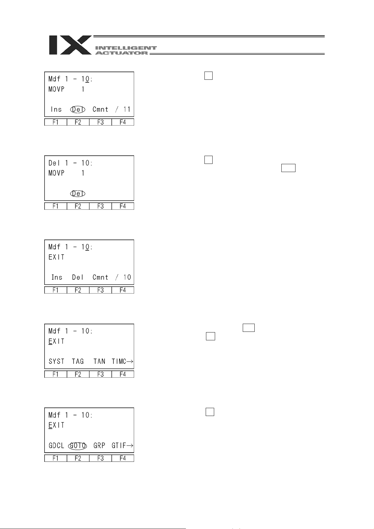
Press the F2 (Del) key.
Press the F2 (Del) key again.
(When canceling deletion, press the ESC key.)
Press the return key to move the cursor to the
location of commands.
Display “GOTO” with 9 of the ten-key numeric
pad or the SF key.
38
Select the F2 (GOTO) key and press the return key.
Page 42

Enter the same numeric value as the one input for
“TAG” operation 1 for operation 1. Enter 1 here and
press the return key.
Press the WRT key to transfer the program data to
the controller.
* When the screen is changed with the PAGE UP
and PAGE DOWN keys or ESC key before data
transfer, the input data becomes invalid.
Press the ESC key several times to move to the Flsh
screen.
To write the data in flash ROM, press the F1 (Yes)
key.
If not, press the F2 (No) key.
The message “Please wait…” flashes during flash
ROM writing.
* Never turn off the power to the controller at this
time.
When flash ROM writing is completed, the screen
returns to the Mode Selection screen.
39
Page 43

10. Program Execution
Now, operate the program created in “9. Simple Operating Procedures.”
10-1. Operation check
Press the F2 (Play) key to move to the Play mode
screen.
Play mode screen
All programs completed
The following 3 items on the Play mode screen exist.
F1 (Run): Moves to the screen for inputting the
program No. to execute.
F2 (TSts): Moves to screen for monitoring the
status of the task in execution.
F3 (AStop): Completes all programs in execution.
(The F2 and F3 keys are function keys to be used
after program execution.)
T ask status
The cursor is located at the program No.
Enter the program No. to execute with the ten-key
numeric pad or the PAGE UP and PAGE DOWN
keys, and confirm it with the return key.
40
Page 44

The screen has moved to the Run mode selection screen.
A
Select whether to make a run by 1 step of the program or to make a continuous run.
Run mode selection
Start a continuous run
with the F1 (Strt) key.
Continuous run mode Step run mode
Start a step run with the
F2 (Step) key.
The program step currently in execution is
displayed (excluding the continuous
movement system command).
Pressing the F2 (Sus) key changes to a
step run.
Pressing the F3 (Stop) key completes
running.
fter the program step currently in execution
has been displayed, the next step is
displayed.
Every time the F2 (Step) key is pressed, the
program is executed by 1 step.
Pressing the F1 (Cont) key changes to a
continuous run.
Pressing the F3 (Stop) key completes
running.
Monitor while in running
F1 (Posi): Current position display
F2 (LFlg): Local flags
F3 (LVar): Local variables
Monitor while in running
F1 (Posi): Current position display
F2 (LFlg): Local flags
F3 (LVar): Local variables
Note: While the Teaching Pendant is left connected, it is in the “Safety Velocity Specified” state.
Therefore, the maximum velocity always becomes 250 mm/sec or lower for CP motion and 3%
or less for PTP motion regardless of the program and parameter setting.
For the selection of the safety velocity between “Effect” and “Not Effect”, refer to “17-8. Safety
velocity.”
41
Page 45

10-2. Setting of break point
The break points in a continuous run can be set.
Press the F4 (Brk) key on the Run mode selection screen or Run mode screen.
Program no.
B: Set brake point
Blank: Release brake point
Step No.
Select the step No. to set the break point with the
PAGE UP and PAGE DOWN keys.
Every time the F1 (Set) key is pressed, the break
point is set or cleared.
When clearing all the set break points, press the F2
(AClr) key.
When setting the break point and making a
continuous run, the program temporarily stops
before the execution of the command of the set step
No.
To restart a continuous run after the stop, press the
F1 (Cont) key. Pressing the F2 (Step) key makes a
step run.
10-3. Monitor while in running
The actuator’s current positions or data in the local area can be monitored while in a continuous
run or step run.
Press the SF key on the continuous run mode or step run mode screen.
Monitor items are displayed in the function key
section.
F1 (Posi): Current position display
F2 (LFlg): Local flags
F3 (LVar): Local variables
(1) Current position display
The current positions of the actuator are displayed.
Select the F1 (Posi) key on the Run mode screen.
Mode flow:
N/F at the end of the position data indicates the
servo ON/OFF condition.
N: Servo ON, F: Servo OFF
42
Page 46

(2) Local flags
The ON/OFF conditions of local flags are displayed. The conditions of local flags can be
changed between ON and OFF.
Select the F2 (LFlg) key on the Run mode screen.
Mode flow:
Every time the F1 (0/1) key is pressed, the local flag
where the cursor is located can be changed between
ON and OFF.
Move the cursor with the return key or ← key.
Every time the PAGE UP or PAGE DOWN key is
pressed, the flag Nos. are shifted by 20 and
(3) Local variables
The local variable/local string descriptions are displayed. In addition, a numeric value can be
assigned to the local variable while a character string can be assigned to the local string.
Select the F3 (LVar) key on the Run mode screen.
displayed.
Local variables are displayed by dividing them into
the following 3 types:
F1 (Itg): Integer
F2 (Real): Real number
F3 (Str): String
① Local integer variable
Mode flow:
The cursor is located at the data (variable description). Entering a numeric value with the ten-key
numeric pad and pressing the return key can assign a value. Move the cursor with the return key
or ← key.
The variable No. can also be changed with the PAGE UP and PAGE DOWN keys.
② Local real variable
Mode flow:
43
Page 47

③ Local string
Mode flow:
The cursor is located at the data (column). Entering
an ASCII code with the ten-key numeric pad and
pressing the return key can assign characters. (A to
F of hexadecimal notation can be input by changing
Num to Alph with the F1 [Alph/Num] key.)
Move the cursor with the return key or ← key.
The PAGE UP and PAGE DOWN keys display the
column Nos. by shifting the numbers by 20.
44
Page 48

11. Position Editing
11-1. Mdi (numeric input)
Method of inputting a numeric value with the ten-key numeric pad for position data
For the data input of the coordinate position with the ten-key numeric pad, refer to “9. Simple
Operating Procedures.”
Method of inputting Vel (velocity), Acc (acceleration), and Dcl (deceleration) for each position No.
Example of Mdi (numeric input):
Mode flow to numeric input screen: Position No.
Vel is displayed in the function key section on the
data input screen for each axis. Press the F2 (Vel)
key.
+ return
Position No.
Vel, Acc, and Dcl input screen
Move the cursor with the return key, enter data in a
required section with the ten-key numeric pad, and
press the return key.
After entering data, press the WRT key to transfer
the data to the controller.
* When the screen is changed with the PAGE UP
and PAGE DOWN keys or ESC key before data
transfer, the input data becomes invalid.
The position No. is incremented and the next Vel,
Acc, and Dcl input screen is displayed.
45
Page 49

11-2. Teac (teaching)
Teaching (method in which an actuator is moved to any given position and the current positions of
the actuator are incorporated as data) is the method for inputting position data.
As the methods of moving the actuator to any given position, jog operation, inching operation,
and manual operation in an emergency stop condition exist.
The basic flow of teaching is as follows:
① Move the actuator. (Jog operation, inching operation, or manual operation in a servo OFF
condition) Select the position No. and axis No. for data input.
② Incorporate the current positions of the actuator onto the teaching screen.
③ Transfer the data to the controller.
Repeat the steps of ① through ③ above to input the position data by teaching.
Teaching is executed mainly on the teaching screen.
Mode flow to teaching screen:
Position No.
Position No. selection screen
The cursor is located at the
position No.
Position
No.
+
Return
Axis-specific data input screen
The cursor is located at the
position data of any axis.
Indicates the current arm system.
R: Right arm, L: Left arm
Indicates the coordinate system for jog
operation.
[W n]: Work coordinate system
n: Work coordinate system No.
([W 0]: Base coordinate system)
[T n]: Tool coordinate system
n: Tool coordinate system No.
[ A]: Each axis system
Caution
It is required to perform teaching with
the same work coordinates system
selection No., tool coordinate system
selection No. and arm system as those
for actual operation.
If any is different, positioning cannot be
performed as intended.
46
Page 50

(1) Teaching screen
The teaching screen consists of two screens including 'position No. selection screen' and
'axis-specific data input screen.
On the position No. selection screen, teaching (current-position incorporation/clear) is given to all
axes simultaneously. On the axis-specific data input screen, teaching is given on an axis basis.
① Position No. selection screen
Function key descriptions
F1(Disp): It switches the display between the
input data screen and the current
position display.
F2(Scan): It incorporates the current positions
of all axes onto the screen.
F3(Clr): It clears the all-axis data of the
position No. selected.
F4(JCrd): It changes the coordinate system for
jog operation.
F1(Vel): It inputs data of velocity, etc., for each
position No.
F2(JVel): It sets the jog velocity, etc.
F3(MVel): It sets movement velocity in the
continuous movement mode (Cont)
or with the MOVE key.
F4(Arm): It changes the arm system. (Servo
ON status required in advance)
Note: The arm operates.
F1(Crd#): It selects the coordinate system No.
F2(In): It monitors input ports.
F3(Out): It monitors output ports.
F4(UsrO): It turns ON/OFF the output ports
(sequential 8 points at the maximum
set to parameters).
(It is required to set the I/O
parameters No. 74 and No. 75.)
F1(Cont): It moves to the continuous movement
mode.
F2(Jump): It sets jump movement.
(Teaching Pendant Application Part
Ver. 1.13 or later)
Enter the position No. with the ten-key numeric pad, and press the return key to move to the
axis-specific data input screen.
47
Page 51

② Axis-specific data input screen
Function key descriptions
F1(Disp): It switches the display between the
input data screen and the current
position display.
F2(Scan): It incorporates the current positions
of all axes onto the screen.
(Teaching Pendant Ver. 1.02 or later)
F3(Canc): It clears the all-axis data of the
position No. selected.
F4(JCrd): It changes the coordinate system for
jog operation.
F1(Vel): It inputs data of velocity, etc., for each
position No.
F2(JVel): It sets the jog velocity, etc.
F3(MVel): It sets movement velocity in the
continuous movement mode (Cont)
or with the MOVE key.
F4(Arm): It changes the arm system. (Servo
ON status required in advance)
Note: The arm operates.
F1(Crd#): It selects the coordinate system No.
F2(In): It monitors input ports.
F3(Out): It monitors output ports.
F4(UsrO): It turns ON/OFF the output ports
(sequential 8 points at the maximum
set to parameters).
(It is required to set the I/O
parameters No. 74 and No. 75.)
F1(Cont): It moves to the continuous movement
mode.
48
Page 52

11-3. Jog movement direction and coordinate system
(1) Jog keys and movement directions
The movement direction during jog operation changes according to the coordinate system No.
selected.
The status before shipment is the base coordinate system (work coordinate system No. 0)
and tool coordinate system No. 0.
For the setting of coordinate system data, refer to “13. Coordinate System Data Editing.”
① Jog movement on base coordinate system
The jog keys and movement directions on the base coordinate system are as shown below.
Jog movement on base coordinate
system (work coordinate system No.
0)
Left arm system
To change the coordinate system for
jog operation, press the F4 (JCrd)
key.
To switch between the input data
screen and the current position
display, press the F1 (Disp) key.
The current position display on the teaching screen
is the position on the work coordinate system
selected.
When the tool coordinate system No. is also
selected, the coordinate value of the tool tip position
is applied.
49
Page 53

② Jog movement on work coordinate system
Example) The jog keys and movement directions on the work coordinate system No. 1 are as
shown below. The offset values from the work coordinate system No. 1 become Xofw1 = 150,
Yofw1 = 200, Zofw1 = 0, and Rofw1 = 30.
Origin of work
coordinate
system No. 1
Jog movement on work
coordinate system No. 1
Left arm system
To change the coordinate system for
jog operation, press the F4 (JCrd)
key.
To switch between the input data
screen and the current position
display, press the F1 (Disp) key.
The current position display on the teaching screen
is the position on the work coordinate system
selected.
When the tool coordinate system No. is also
selected, the coordinate value of the tool tip position
is applied.
50
Page 54

③ Jog movement on tool coordinate system
Example) The jog keys and movement directions on the tool coordinate system No. 1 are as
shown below. The offset values from the tool coordinate system No. 1 become Xoft1 = 45,
Yoft1 = 35, Zoft1 = -10, and Roft1 = 45.
D-cut surface
Jog movement on tool
coordinate system No. 1
Left arm system
Tool tip
The current position display on the teaching screen
is the coordinate position of the tool tip of the tool
coordinate system No. on the work coordinate
system selected.
To change the coordinate system for
jog operation, press the F4 (JCrd)
key.
To switch between the input data
screen and the current position
display, press the F1 (Disp) key.
Pressing the jog key for the 4th axis (R axis) performs rotary movement centering on the tool tip
as shown below.
51
Page 55

④ Jog movement on each axis system (jog movement on each arm)
Each arm, jog keys and movement directions are as shown below.
In the case of each axis
system, the position display on
the teaching screen cannot be
incorporated.
Jog movement on each
axis system
To switch between the input data
screen and the current position
display, press the F1 (Disp) key.
To change the coordinate system for
jog operation, press the F4 (JCrd)
key.
52
Page 56

(2) Selection of coordinate system No.
Use the SF key to display Crd# on the teachi ng
screen.
Press the F1 (Crd#) key.
Enter the work coordinate system No.
Enter the tool coordinate system No.
This is a screen displayed when the work
coordinate system No. 1 and the tool coordinate
system No. 1 are selected.
Press the ESC key to return to the teaching
screen.
The coordinate values displayed indicate the
tool tip position of the tool coordinate system
No. 1 on the work coordinate system No. 1.
53
Page 57

1 1-4. Actuator operation
Jog the actuator or move it to the input (transferred) position data by using the Teaching Pendant.
Operate the actuator on the teaching screen.
Mode flow to teaching screen:
(1) Jog operation
Press the ON/OFF key in a teaching screen
condition to turn the servo ON.
To check the servo ON/OFF status, press the F1
(Disp) key to display the current position.
Current position display
N: Servo ON
F: Servo OFF
Before operation, check the jog operation coordinate
system selected.
Press the 1→ 2→ 3→ 4→ ←1 ←2 ←3
←4 keys to move the actuator to any given p osition.
(1 to 4 indicates axis No., the right arrow indicates
the coordinate plus direction, and the left arrow
indicates the minus direction.)
Change of jog velocity
The actuator movement velocity under jog operation
is changed.
Display “Jvel” (jog velocity) in the function key
section on the teaching screen and press the
corresponding function key.
(“Jvel” is not displayed without pressing the SF key
depending on the screen condition.)
Jog velocity: 50 mm/sec
Enter Vel (velocity), Acc (acceleration), and Dcl
(deceleration) under jog operation with the ten-key
numeric pad and press the return key. Dis (inching
distance) should be 0.000. In addition, the inching
distance can also be set from this screen.
Return to the teaching screen with the ESC key and
execute jog operation.
54
Page 58

Y
(2) Inching operation
Mode flow:
Inching distance: 0.1 mm
Set the inching distance (travel made every time the
JOG key is pressed once).
Enter a numeric value for Dis (inching distance) with
the ten-key numeric pad on the jog velocity change
screen. The numeric input range is between 0.001
and 1.000 (unit: mm). Return to the teaching screen
with the ESC key to execute inching operation.
Clicking the jog key once makes 1-inching distance
movement.
Clicking any of 1→ through 4→ makes inching
movement in the coordinate plus direction, while
clicking any of ←1 through ←4 makes inching
movement in the coordinate minus direction.
Pressing and holding the JOG key changes to jog
operation. In approximately 1.6 seconds after the
JOG key is pressed, inching operation changes to
jog operation and further continuing to press the key
changes the jog velocity per second as follows:
1→10→50→100 mm/sec.
(3) Manual movement under emergency stop condition
Press the EMERGENCY STOP button key in a
teaching screen condition to turn the servo OFF.
Emergency stop input screen
Press the ESC key to return to the teaching screen.
Servo OFF
Move the actuator to any given position manually.
To move the Z-axis or R-axis manually, the brake
must be released. Consequently, the Z-axis may
drop under the weight of the hand attached to the tip
when the brake is released. Do not perform teaching
by manual movement of the Z-axis or R-axis.
Danger
Be sure to perform manual teaching while the EMERGENC
STOP button is being pressed.
55
Page 59

(4) Arm system change
Change the current arm system over to the opposite arm system. (Right arm → left arm, left
arm → right arm)
The 1st arm does not move and the 2nd arm moves in such a way that it becomes
straightened with the 1st arm.
Change the arm system on the teaching screen.
Mode flow to teaching screen:
Press the SF key to display “Arm” in the function key section.
Press the F4 (Arm) key.
Note: When the version of the Teaching Pendant
Application Part is earlier than 1.13, pressing the F4
(Arm) key starts to move the 2nd arm.
Select whether or not to change the arm system.
(Teaching Pendant Application Part Ver. 1.13 or
later)
To execute: Press the F1 (Yes) key. The 2nd arm
starts to move.
Not to execute: Press the F2 (No) key. The screen
returns to the previous screen.
When the F1 (Yes) key is pressed, the display
changes over to the screen under movement and the
2nd arm moves until it becomes straightened with
the 1st arm.
56
Page 60

(5) Incorporation of current positions as data
Check the work coordinate system No., tool coordinate system No., and arm system currently
selected. (Mode flow: )
The selected actuator’s location is incorporated as position data onto the teaching screen.
Enter the position No. into which data is incorporated
with the ten-key numeric pad on the position No.
selection screen, and press the return key.
Or, select the position No. into which data is
incorporated with the PAGE UP and PAGE DOWN
keys on the data input screen.
(6) Transfer to controller
On the position No. selection screen, pressing the
F2 (Scan) key incorporates the current position data
for all axes.
On the axis-specific data input screen, pressing the
F2 (Scan) key incorporates the current position data
of the axis over which the cursor is located. (The
data is incorporated on an axis basis. The left figure
indicates the case of data incorporation on the
axis-specific data input screen.)
The incorporated data is transferred to the controller.
Press the WRT key in a teaching screen condition.
Store the incorporated data in the controller’s
memory.
Pressing the WRT key increments the position No.
by 1.
What can be transferred to the controller is the data
on one display screen. It is not possible to transfer
the data of more than one position No. at a time.
* When the screen is changed with the PAGE UP
and PAGE DOWN keys or ESC key before data
transfer, the input data becomes invalid.
57
Page 61

(7) I/O monitoring
Input and output ports can be monitored during teaching operation.
① I/O monitoring
Select In or Out among the function keys in a teaching screen condition.
In: Input ports Out: Output ports
Mode flow: Mode flow:
Input ports
Output ports
Pressing the F1 (0/1) key can turn OF F/ON (0/1) the
output port at the cursor location. Every time the F1
key is pressed, the port is changed between OFF
and ON (0 and 1).
58
Page 62

(8) Movement
The actuator is moved to the location of the position data transferred to the controller.
(Check the location of the teaching position data.)
Mode flow to teaching screen:
Position No. to move
Select the position No. you want to move in a
teaching screen condition.
Press the ON/OFF key to turn the servo ON.
To check the servo ON/OFF status, press the
F1 (Disp) key.
Pressing the MOVE key starts movement. To
stop movement halfway, press the STOP key.
When checking or changing the movement
velocity, press the F3 (MVel) key to move to the
screen for changing the velocity, etc.
Enter the change data with the ten-key numeric
pad and press the return key. After changing,
return to the previous screen with the ESC key.
Ratio to maximum PTP velocity (axis-specific
parameter No. 28)
Ratio to maximum PTP acceleration (axis-specific
parameter No. 135)
Ratio to maximum PTP deceleration (axis-specific
parameter No. 134)
59
Page 63

(9) Continuous movement
The actuator is continuously moved to the location of the position data transferred to the
controller.
Mode flow to teaching screen:
Position No. to move first
Select the position No. to which you want to
move the actuator first in a teaching screen
condition, and press the return key.
Press the ON/OFF key to turn the servo ON.
To check the servo ON/OFF status, press the
F1 (Disp) key.
Press the F1 (Cont) key.
When checking and changing the movement
velocity, press the F2 (Mvel) key to move to the
screen for changing the velocity, etc.
60
Pressing the MOVE key starts the actuator’s
continuous movement.
Pressing the F1 (Disp) key displays the current
target position data.
Page 64

(10) Jump movement
The actuator is moved to the location of the position data transferred to the controller by
jump motion (arch motion). Before/after normal movement or continuous movement, the
Z-axis is moved up and down.
(Supported by Teaching Pendant Application Part Ver. 1.13 or later)
Z-axis offset value
Target position
Current position
Motion sequence
① Raise the Z-axis from the current position to the top position (Z = 0). (Motion of the Z-axis
only)
② Movement is performed to above the target position by PTP motion while the Z-axis stays
at the top position. (Motion of the X-axis, Y-axis and R-axis only)
③ Lowering is performed to the target position. (Motion of the Z-axis only). When the Z-axis
offset value is set, the Z-axis stops before (above) the target position by the same
amount.
Z-axis offset value: Specify how many millimeters before the target position to stop the
Z-axis. No minus value can be input.
Normal movement
61
Page 65

Setting of jump movement is performed on the teaching screen.
Mode flow to teaching screen:
Press the SF key to display “Jump” in the function key section.
Press the F2 (Jump) key.
Enter 1 to make jump motion effective or 0 to make it
ineffective, and press the return key.
Enter the Z-axis offset value.
Enter the offset value (mm) from the Z-axis target
position coordinate and press the return key.
The set value is effective until the Teaching Pendant
is reset or reconnected.
Press the ESC key to return to the teaching screen.
Selecting the target position No. and pressing the
MOVE key start jump motion.
“J” is displayed at the right side of the position No.
while jump motion is effective.
62
Page 66

(11) User-specified output port operation
The output ports set for the parameter can be easily turned ON/OFF.
Select UsrO among the function keys in a teaching screen condition.
Mode flow:
(A) User-specified output port status
The conditions of user-specified output ports are displayed as “1” (=ON) and “0” (=OFF).
(The conditions are displayed from the first specified port for the number of the specified
ports.)
(B) Current position and servo ON/OFF display
The current position and servo ON/OFF condition (“N”=ON, “F”=OFF) are displayed for
each axis.
(C) Function for operation of user-specified output ports
This is the function for ON/OFF operation of user-specified output ports.
This function is allocated to “Usr1,” “Usr2,” “Usr3”….in this order from the first
user-specified port for the number of specified ports.
(“Usr1” to “Usr4” and “Usr5” to “Usr8” are changed with the SF key.)
ON/OFF operation can be performed for each output port by pressing the function keys
(F1 to F4) corresponding to “Usr1” to “Usr4” and “Usr5” to “Usr8.”
(When the port status display is “0” [OFF], the port ON command is given. When the port
status display is “1” [ON], the port OFF command is given.)
63
Page 67

① Setting of user-specified output port parameters
For the operation method for parameter setting, refer to “14. Parameter Editing.”
The first port No. and the number of ports are set with the following parameters:
▪ Number of ports
I/O parameter No. 74 “Qnt Prt Usr Out” (Number of output ports used by TP user [hand,
etc.])
▪ First port No.
I/O parameter No. 75 “Top No. Use Out” (First output port No. by TP user [hand, etc.])
(Setting example) When the first port No. is set to 308 and the number of ports is set to 8:
“Usr1” (F1 key)
“Usr2” (F2 key)
“Usr3” (F3 key)
“Usr4” (F4 key)
“Usr5” (F1 key)
“Usr6” (F2 key)
“Usr7” (F3 key)
“Usr8” (F4 key)
・・・・・・
Output port 308
・・・・・・
Output port 309
・・・・・・
Output port 310
・・・・・・
Output port 311
・・・・・・
Output port 312
・・・・・・
Output port 313
・・・・・・
Output port 314
・・・・・・
Output port 315
64
Page 68

11-5. Teaching input example
Data is input for the position No. 10 by jog operation and for the position No. 11 by manual
operation under servo OFF.
Select the F1 (Edit) key on the Mode Selection
screen.
Select the F1 (Posi) key.
Select the F2 (Teac) key.
Enter 10 for the position No. with the PAGE UP and
PAGE DOWN keys or the ten-key numeric pad and
confirm it with the return key.
Press the ON/OFF key to turn the servo ON.
65
Page 69

Press the jog key ←1 1→ ←2 2→ to move
the robot to any given position.
Pressing the F2 (Scan) key incorporates the current
position of the axis No. over which the cursor is
located onto the input screen.
Change the screen over to the data input screen with
the F1 (Disp) key. Confirm that the data has been
incorporated.
Press the return key to move the cursor to the next
axis, and press the F2 (Scan) key.
Incorporate the data of the Z-axis and R-axis in the
same way.
66
Press the WRT key to transfer the position data to
the controller.
The position No. advances to 11.
* When the screen is changed with the PAGE UP
and PAGE DOWN keys or ESC key before data
transfer, the input data becomes invalid.
Page 70

r
Press the EMERGENCY STOP button to turn the
servo OFF.
Press the ESC key to return from the Emergency
Stop input screen to the previous screen.
F: Servo OFF
N: Servo ON
Confirm the servo OFF with the F1 (Disp) key.
Move each axis to any given position manually.
Danger
Be sure to perform manual teaching while the
EMERGENCY STOP button is being pressed.
To move the Z-axis or R-axis manually, the brake
must be released. Consequently, the Z-axis may
drop under the weight of the hand attached to the
tip when the brake is released. Do not perform
teaching by manual movement of the Z-axis o
R-axis.
67
Page 71

A
r
xis No. at curso
location
Pressing the F2 (Scan) key incorporates the current
position of the axis No. over which the cursor is
located onto the input screen.
Press the return key to move the cursor to the next
axis, and press the F2 (Scan) key.
Incorporate the data of the Z-axis and R-axis in the
same way.
Press the WRT key to transfer the position data to
the controller.
The position No. advances to 12.
* When the screen is changed with the PAGE UP
and PAGE DOWN keys or ESC key before data
transfer, the input data becomes invalid.
68
Page 72

Complete the position data input by teaching.
Press the ESC key.
Press the ESC key.
Press the ESC key.
Press the ESC key.
To write the data in flash ROM, press the F1 (Yes)
key.
If not, press the F2 (No) key.
69
Page 73

The message “Please wait…” flashes during flash
ROM writing.
* Never turn off the power to the Controller at this
time.
The screen returns to the Mode Selection screen.
70
Page 74

11-6. Copy and movement of position data
The following operating instructions are to copy or move the position data to another position No.
Select the F1 (Edit) key on the Mode Selection
screen.
Positions from which data is copied or moved
First No.
Positions to which data is copied or moved
First No.
Last No.
Select the F1 (Posi) key.
Select the F3 (Copy) key.
Enter the first No. and the last No. of the positions
from which data is copied or moved with the ten-key
numeric pad and press the return key.
Enter the first No. of the positions to which data is
copied or moved with the ten-key numeric pad and
press the return key.
When copying the data, press the F3 (Copy) key.
When moving the data, press the F4 (Move) key.
Press the ESC key to return to the previous screen.
When writing the data in flash ROM, press the ESC
key several times to return to the Flsh screen.
71
Page 75

11-7. Deletion of position data
The following operating instructions are to delete the position data.
Select the F1 (Edit) key on the Mode Selection
screen.
Select the F1 (Posi) key.
Select the F4 (Clr) key.
Position data to delete
First No.
Last No.
Enter the first No. and the last No. of the position
data to delete with the ten-key numeric pad and
press the return key.
When deleting the selected position data, press the
F3 (Clr) key.
When deleting the data for all positions (No. 1
through No. 3000), press the F4(AClr) key.
Press the ESC key to return to the previous screen.
When writing the data in flash ROM, press the ESC
key several times to return to the Flsh screen.
72
Page 76

12. Program Editing
12-1. Program input method
Procedures for input of extension condition (E), input condition (N・Cnd) and output (Pst)
The program input sequence with the Teaching Pendant is different from that on the program edit
screen of the PC-compatible software.
The sequence is as follows: ① command (Cmnd), ② operation 1 (Operand 1), ③ operation 2
(Operand 2), ④ output (Pst), ⑤ extension condition (E) and ⑥ input condition (N・Cnd).
Program edit screen of PC-compatible software
LCD display of Teaching Pendant
⑤ E
① Cmnd
③ Operand 2
Input the program following the program steps below.
Program No. 2
The program step No. 1 is used to input the input condition only and No. 2 is used to input all but
comments.
② Operand 1 ④ Pst
N・Cnd
⑥
73
Page 77

Select the F1 (Edit) key on the Mode Selection
screen.
Select the F2 (Prog) key on the Edit mode screen.
Select the F1 (Mdfy) key on the Edit-Prog screen.
Enter the program No. with the ten-key numeric pad
and press the return key.
74
The cursor has moved to the location of the step No.
Press the return key.
Page 78

Input section for Cmnd
Press the return key.
Input section for Operand 1
Press the return key.
Input section for Operand 2
Press the return key.
Input section for Pst
Press the return key.
Input section for E
Press the return key.
75
Page 79

Input section for N·Cnd
Enter 601 with the ten-key numeric pad and press
the return key.
Press the WRT key to transfer the data of step No. 1
to the controller.
The step No. advances to 2.
* When the screen is changed with the PAGE UP
and PAGE DOWN keys or ESC key before data
transfer, the input data becomes invalid.
Input section for Cmnd
Display CPGE in the function key section with 7 of
the ten-key numeric pad and the SF key.
For the command search method, refer to “9-2.
Creation of program.”
Select the F4 (CPGE) key and press the return key.
76
Input section for Operand 1
Enter 200 with the ten-key numeric pad and press
the return key.
When specifying a variable to Operand 1 indirectly,
select the F3 (*) key first.
When inputting a string to Operand 1, Press the F1
(Num) key to change to F1 (Alph). Input the string
with the F4 (‘) key and the ten-key numeric pad now
functioning for alphabetic input.
Page 80

Input section for Operand 2
(variable indirect specification)
Select the F3 (*) key first, enter 201 with the ten-key
numeric pad, and press the return key.
When inputting a string to Operand 2, follow
the procedure of Operand 1.
Input section for Pst
Enter 900 with the ten-key numeric pad and press
the return key.
When specifying a variable to Operand 1
indirectly, select the F3 (*) key first.
Input section for E
Select the F2 (A) key and press the return key.
Input the extension condition of virtual ladder
task to this screen by the function keys as
well.
Complete the program input. Return to the Flsh screen with the ESC key.
Input section for N·Cnd
Select F3 (N) key first, enter 600 with the ten-key
numeric pad, and press the return key.
Press the WRT key to transfer the data of step No. 2
to the controller.
The step No. advances to 3.
* When the screen is changed with the PAGE UP
and PAGE DOWN keys or ESC key before data
transfer, the input data becomes invalid.
77
Page 81

12-2. Symbol input during program editing
Symbols can be input when the cursor is located at Operand 1/Operand 2 (operation 1/2), Pst
(output), or Cnd (input condition) and “Sym” is displayed in the function key section.
Input example)
Symbol input in the following program step:
The position No. 10 is symbolized by “TAIKIITI.”
Select the F2 (Sym) key in the function key section
when the cursor is located at Operand 1. The
screen moves to the Edit-Sym screen.
Select the item for symbol editing with a function
key. In this case, select the F4 (Posi) key to edit the
position No.
Enter 10 for the position No. with the ten-key
numeric pad and press the return key.
78
Page 82

The ten-key numeric pad now functions for
alphabetic input.
Enter “TAIKIITI.”
For the input method, refer to “13. Symbol Editing.”
Press the WRT key to transfer the symbol data to
the controller. The display returns to the previous
edit screen.
The letter “S” indicates that
the symbol is used.
The Teaching Pendant cannot display the input
symbol as it is in relation to the LCD display.
In this case, “S10” is displayed instead of “TAIKIITI.”
Selecting the F2 (Sym) key when the cursor is
located at the already-symbolized item moves
to the symbol edit screen. The symbol can
then be changed.
Definition value of symbol
Press the WRT key to transfer the data in this
program step to the controller.
When completing the program input, return to the Flsh screen with the ESC key.
79
Page 83

12-3. One-line comment input
A comment is input for the program step (invalid step) with numeric values, alphabetic letters, and
symbols (*, ・, and _).
Mode flow: Program No. + return
Move the cursor to the step No. for comment input.
Press the F3 (Cmnt) key.
“C” is displayed next to the step No.
Press the return key.
Every time the F1 key is pressed, the display in the
F1 key field is changed between “Alph” and “Num.”
Alphabetic input
Display “Alph” in the F1 key field.
Alphabetic letters are allocated for each key of the
ten-key numeric pad.
Example) Every time 6 of the ten-key numeric
pad is pressed, the display changes as follows: P→
Q→ R→ p→q→ r→P→ …. Display the alphabetic
letters for input and confirm it with the return key.
The left figure displays “P.”
The figure at the left is the display example when
“Palette” is input.
80
Page 84

Numeric input
Press the F1 key to display “Num.”
Enter a numeric value with the ten-key numeric pad.
The figure at the left is the display example when “1”
is input continuously after “Palette.”
After completing comment input, press the return
key again.
Press the WRT key to transfer the input data to the
controller.
* When the screen is changed with the PAGE UP
and PAGE DOWN keys or ESC key before data
transfer, the input data becomes invalid.
The screen advances to the next step No.
When completing program input, return to the Flsh screen with the ESC key.
Note: The data of double byte characters input with PC-compatible software cannot be displayed
on the Teaching Pendant.
81
Page 85

12-4. Copy and movement of program
The following operating instructions are to copy or move a program to another program No.:
Select the F1 (Edit) key on the Mode Selection
screen.
Program No. from which a
program is copied or moved
Program No. to which a
program is copied or moved
Number of steps of the
specified program
Total number of steps
Select the F2 (Prog) key.
Select the F2 (Copy) key.
Enter the program No. from which a program is
copied or moved with the ten-key numeric pad and
press the return key.
Enter the program No. to which a program is copied
or moved with the ten-key numeric pad and press
the return key.
When copying the data, press the F2 (Copy) key.
When moving the data, press the F3 (Move) key.
82
Press the ESC key to return to the previous screen.
Then, press the ESC key several times to return to
the Flsh screen.
Page 86

12-5. Deletion of program
A
The following operating instructions are to delete a program:
Select the F1 (Edit) key on the Mode Selection
screen.
Select the F2 (Prog) key.
Select the F2 (Clr) key.
Program No. to delete
Enter “0.”
Enter the program No. to delete with the ten-key
numeric pad and press the return key.
① When deleting one program, pressing the F2
(Clr) key in the example on the left deletes the
program No. 3.
Total number
of steps
series of programs
First No.
Last No.
② When deleting a series of multiple programs,
pressing the F2 (Clr) key in the example on the
left deletes the programs No. 4, No. 5 and No. 6.
③ When deleting all the progr ams (N o. 1 to No. 64),
press the F3 (Aclr) key.
83
Page 87

Press the ESC key to return to the previous screen.
Then, press the ESC key several times to return to
the Flsh screen.
84
Page 88

12-6. Flash ROM writing
If data is only transferred to the controller after program editing, the edited program is erased
when the power is turned on again or software is reset.
To maintain the edited data even if the power is turned on again or software is reset, the data is
written in flash ROM.
Return to the Flsh screen with the ESC key from the edit completion screen.
To write the data in flash ROM, press the F1 (Yes)
key.
If not, press the F2 (No) key.
The message “Please wait…” flashes during flash
ROM writing.
* Never turn off the power to the Controller at this
time.
Flash ROM writing is completed.
Press the ESC key to return to the Edit screen.
85
Page 89

13. Coordinate System Data Editing
As the coordinate system data of the IX series, there are the work coordinate system data, tool
coordinate system data and simple interference check zone.
Select the F1 (Edit) key on the Mode Selection
screen.
Press the SF key on the Edit mode screen to
display Crd.
Press the F1 (Crd) key.
Select the F1 (Mdfy) key.
Coordinate system data selection screen
86
Select the coordinate system to be edited from this
screen.
F2 (Work) key: Work coordinate system
F3 (Tool) key: Tool coordinate system
F4 (Itfr) key: Simple interference check zone
Page 90

Origi
13-1. Editing of work coordinate system data
As an input example of the work coordinate system data, a coordinate system as shown below is
set for the work coordinate system No. 1.
(Motion range at the arm length 500-type stroke)
n of work
coordinate system No. 1
The offset values from the work coordinate system No. 1 are Xofw1 = 150, Yofw1 = 200, Zofw1 =
0 and Rofw1 = 30.
Mode flow:
This is the work coordinate system No. selection
screen.
The cursor is located at the work coordinate system
No.
To select the work coordinate system No., enter the
No. with the ten-key numeric pad or the PAGE UP
and PAGE DOWN keys, and confirm it with the
return key.
This example indicates the setting of the work
coordinate system No. 1.
Press the return key as it is.
The cursor is located at the X-axis offset value data.
Enter 150 and press the return key.
87
Page 91

The cursor is located at the Y-axis offset value data.
Enter 200 and press the return key.
The cursor is located at the Z-axis offset value data.
Enter 0 and press the return key.
The cursor is located at the R-axis offset value data.
Enter 30 and press the return key.
Transfer the data with the WRT key.
The screen advances to the edit screen for the work
coordinate system No. 2.
88
Complete editing of the work coordinate system data
and write data in flash ROM.
Pressing the ESC key moves the cursor to the
location of the work coordinate system No.
Page 92

Pressing the ESC key returns the cursor to the
coordinate system data selection screen.
Coordinate system data selection screen
Pressing the ESC key again returns to the Flsh
screen.
(Return by 3 screens)
To write the data in flash ROM, press the F1 (Yes)
key.
If not, press the F2 (No) key.
The message “Please wait…” flashes during flash
ROM writing.
* Never turn off the power to the Controller at this
time.
The screen returns to the Mode Selection screen.
89
Page 93

13-2. Editing of tool coordinate system data
As an input example of the tool coordinate system data, a tool as shown below is set for the tool
coordinate system No. 1.
R-axis
Tool
Tool tip
Tool tip
D-cut surface
Tool mounting surface center
The offset values from the tool coordinate system No. 1 become Xoft1 = 45, Yoft1 = 35, Zoft1 =
-10 and Roft1 = 45.
Mode flow:
This is the tool coordinate system No. selection
screen.
The cursor is located at the tool coordinate system
No.
To select the work coordinate system No., enter the
No. with the ten-key numeric pad or the PAGE UP
and PAGE DOWN keys, and confirm it with the
return key.
This example indicates the setting of the tool
coordinate system No. 1.
Press the return key as it is.
The cursor is located at the X-axis offset value data.
Enter 45 and press the return key.
90
Page 94

The cursor is located at the Y-axis offset value data.
Enter 35 and press the return key.
The cursor is located at the Z-axis offset value data.
Enter -10 and press the return key.
The cursor is located at the R-axis offset value data.
Enter 45 and press the return key.
Transfer the data with the WRT key.
The screen advances to the edit screen for the tool
coordinate system No. 2.
Complete editing of the tool coordinate system data
and write data in flash ROM.
Pressing the ESC key moves the cursor to the
location of the tool coordinate system No.
91
Page 95

Pressing the ESC key returns the cursor to the
coordinate system data selection screen.
Coordinate system data selection screen
Pressing the ESC key again returns to the Flsh
screen.
(Return by 3 screens)
To write the data in flash ROM, press the F1 (Yes)
key.
If not, press the F2 (No) key.
The message “Please wait…” flashes during flash
ROM writing.
* Never turn off the power to the Controller at this
time.
The screen returns to the Mode Selection screen.
92
Page 96

13-3. Editing of simple interference check zone
It is required to input the following 3 items to set the simple interference check zone:
▪ 2-point position data to define the zone. (Input the values of the base coordinate system.)
▪ Output port No. or global flag No. for output during zone invasion.
▪ Error type at zone invasi on time. (0: No error-handling, 1: Message level error, 2: Motion reset
level error.)
As an input example of the simple interference check zone, a zone as shown below is set for the
simple interference check zone No. 1.
Base coordinate values of Ⓐ: Xb = 475, Yb = -50, Zb = 150, Rb = 0
Base coordinate values of Ⓖ: Xb = 400, Yb = 50, Zb = 200, Rb = 180
Output port for output during zone invasion: No. 311
Error type at zone invasion time: 1
Mode flow:
This is the simple interference check zone No.
selection screen.
The cursor is located at the simple interference
check zone No.
To select the simple interference check zone No.,
enter the No. with the ten-key numeric pad or the
PAGE UP and PAGE DOWN keys, and confirm it
with the return key.
This example indicates the setting of the simple
interference check zone No. 1.
Press the return key as it is.
93
Page 97

Input of base coordinate values of Ⓐ
The cursor is located at the X-axis data.
Enter 475 and press the return key.
The cursor is located at the Y-axis data.
Enter -50 and press the return key.
The cursor is located at the Z-axis offset value data.
Enter 150 and press the return key.
The cursor is located at the R-axis offset value data.
Enter 0 and press the return key.
94
Press the F3 (Crd#) key to input the other position
data.
Page 98

Input of base coordinate values of Ⓖ
Enter the base coordinate values of Ⓖ in the same
way as A.
Set the output port/global flag and error type
Press the F4 (P/E) key.
Output port/global flag No. and error type input
screen
Press the return key.
Enter the output port No. 311 and press the return
key.
Enter the error type 1 and press the return key.
95
Page 99

Transfer the data with the WRT key.
The screen advances to the edit screen for the
simple interference check zone No. 2.
When the axial pattern of Ⓐ does not agree with
that of Ⓖ, the “9FO” error occurs.
When the axial pattern of Ⓐ and Ⓖ is 0, the “9F1”
error occurs if the output port or error type is
specified.
Complete editing of the tool coordinate system data
and write the data in flash ROM.
Pressing the ESC key moves the cursor to the
location of the simple interference check zone No.
Pressing the ESC key returns the cursor to the
coordinate value input screen.
Pressing the ESC key moves the cursor to the
location of the tool coordinate system No.
Pressing the ESC key again returns to the Flsh
screen.
(Return by 4 screens)
96
Page 100

To write the data in flash ROM, press the F1 (Yes)
key.
If not, press the F2 (No) key.
The message “Please wait…” flashes during flash
ROM writing.
* Never turn off the power to the Controller at this
time.
The screen returns to the Mode Selection screen.
97
 Loading...