

Page 1

X-SEL Multi-point DIO Board
(K-Type Controller Expansion Slot /
J-Type Controller Standard Slot)
Operating Manual
Table of Contents
1. Overview................................................................................................................. 1
1.1 Features.............................................................................................................. 1
1.2 Board Variations.................................................................................................. 1
2. Configuration .......................................................................................................... 2
2.1 System Configuration.......................................................................................... 2
3. Specifications.......................................................................................................... 3
3.1 I/O Specifications ................................................................................................ 3
4. External Interface Specifications............................................................................. 4
4.1 Terminal Assignments for External DIO Interface................................................ 4
4.2 IO24V Power Input.............................................................................................. 7
5. I/O Circuits.............................................................................................................. 8
5.1 Input ................................................................................................................. 8
5.2 Output ................................................................................................................. 9
6. Examples of Interface........................................................................................... 10
Page 2
INTELLIGENT ACTUATOR
This board is a multi-point DIO board equipped with 48 input points and 48 output points for use with an XSEL controller.
1. Overview
1.1 Features
[1] 96 I/O points in one board
One board provides 48 input points and 48 output points, thus effectively adding to the I/O control
capability of your X-SEL controller.
[2] DIO interface supporting both NPN and PNP
Just like the current I/O board, the DIO interface is also available in the NPN or PNP specification.
[3] Overcurrent and I/O-power monitor function
The DIO board detects overcurrent in the DO port and monitors the I/O power-supply voltage. If an
out-of-spec current or voltage is detected, the DO output will be cut off. Note, however, that the
overcurrent detection value of the DIO board is 400 mA per 24 points, which is different from the
threshold specification of the current I/O board (400 mA per 8 points).
1.2 Board Variations
This board comes in the variations listed in the table below.
Table 1-1 Board Variations
Multi-point DIO Board for Expansion Slot of K-Type Controller
Model Name
IA-IO-3204-NP X-SEL expansion multi-point DIO board, NPN specification
IA-IO-3204-PN X-SEL expansion multi-point DIO board, PNP specification
Multi-point DIO Board for Standard Slot of J-Type Controller
Model Name
IA-IO-3205-NP X-SEL standard multi-point DIO board, NPN specification
IA-IO-3205-PN X-SEL standard multi-point DIO board, PNP specification
1
Page 3
INTELLIGENT ACTUATOR
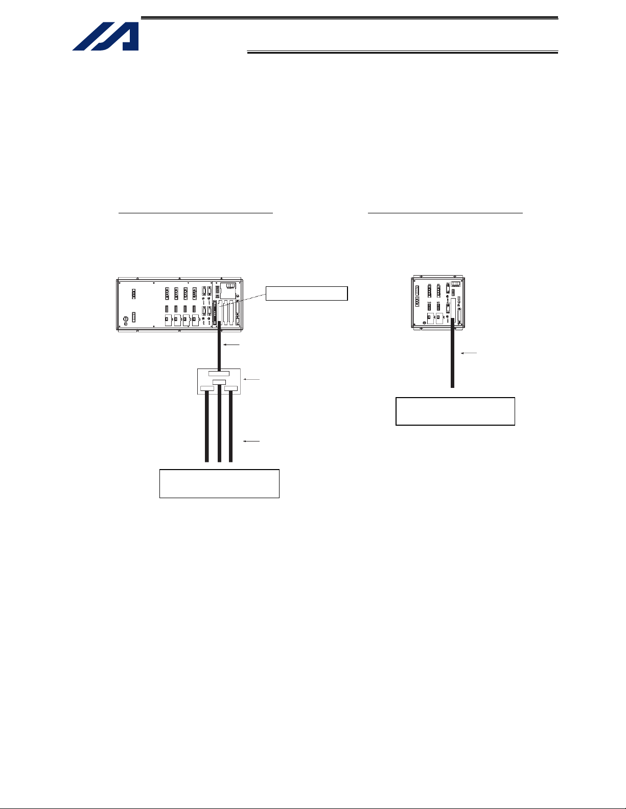
2. Configuration
2.1 System Configuration
This board is installed in an expansion I/O slot of an X-SEL K-Type controller, or in a standard I/O
slot of a J-Type controller, for use in signal communication with external DIO devices.
Fig. 2-1 Connection Example 1 Fig. 2-2 Connection Example 2
K-Type controller J-Type controller
PLC, sensor or
other peripheral equipment
Multi-point I/O board
Half-pitch I/O flat cable
(w/ connectors on both ends)
Model: CB-X-PIOH020-H6
(Supplied with terminal block TU-MA96)
Dedicated terminal block for
multi-point I/O board
Model: TU-MA96 (NPN specification)
TU-MA96-P (PNP specification)
I/O flat cable (w/o connector on either end)
Model: CB-RCBC-PIO020
(3 cables are supplied with terminal block TU-MA96)
PLC, sensor or
other peripheral equipment
Half-pitch I/O flat cable
(w/ connector on one end)
Model: CB-X-PIOH020
2
Page 4
INTELLIGENT ACTUATOR
3. Specifications
3.1 I/O Specifications
Table 3-1 I/O Specifications
Numbers of I/O points 48 input points, 48 output points
External power-supply voltage
Input insulation Photocoupler insulation
Input current Max. 7 mA/point
Input leak current Max. 1 mA/point
Output insulation Photocoupler insulation
Output element Transistor
Maximum output load current 50 mA/point (400 mA/24 points)
Output leak current Max. 0.1 mA/point
Item Specification
24 VDC ± 10%
3
Page 5
INTELLIGENT ACTUATOR
4. External Interface Specifications
4.1 Terminal Assignments for External DIO Interface
Table 4-1 Overview of Multi-point DIO Interface Specifications
Item Overview Remarks
Connector 100-pin half-pitch flat connector HIF6-100PA-1.27DS (by Hirose)
Connector name External DIO connector
External power supply
DI 48 points
DO 48 points
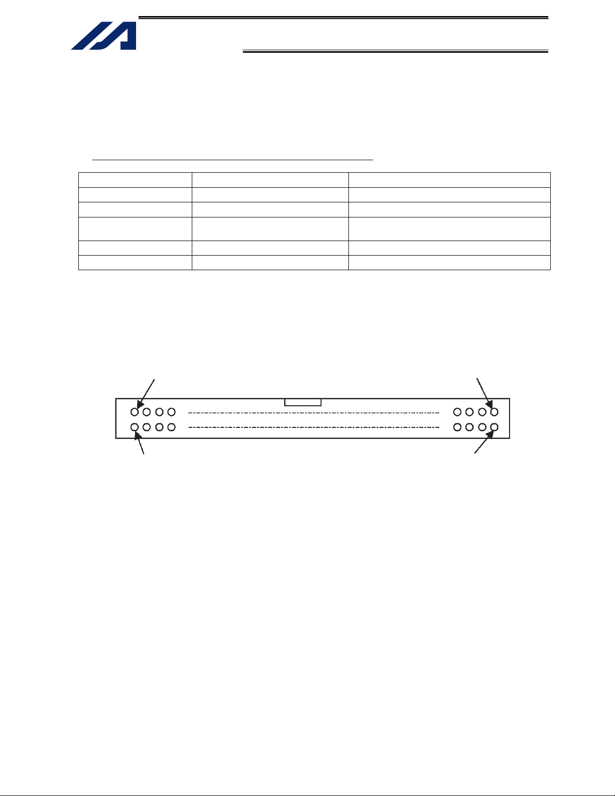
Pin layout (connector fitting surface)
Row A
Row B
Note: In the case of the K-Type expansion DIO board, the external power-supply terminals for IN024 to
047/OUT324 to 347 (pin 26 (24 V), pin 100 (0 V)) are connected internally to the IO24V powersupply connector on the panel board.
Pin 50
Pin 100
24 VDC ± 10%
A separate power supply is used for each
group of 24 DIs/24 DOs.
Pin 1
Pin 51
4
Page 6

INTELLIGENT ACTUATOR
The table below lists the terminal assignments for the DIO interface.
Row Pin No. Category Remarks (Note 1) Row Pin No. Category Remarks (Note 1)
1
2 000 52 301
3 001 53 302
4 002 54 303
5 003 55 304
6 004 56 305
7 005 57 306
8 006 58 307
9 007 59 308
10 008 60 309
11 009 61 310
A
A
12 010 62 311
13 011 63 312
Input
14 012 64 313
15 013 65 314
16 014 66 315
17 015 67 316
18 016 68 317
19 017 69 318
20 018 70 319
21 019 71 320
22 020 72 321
23 021 73 322
24 022 74
25
26
27 024 77 325
28 025 78 326
29 026 79 327
30 027 80 328
31 028 81 329
32 029 82 330
33 030 83 331
34 031 84 332
35 032 85 333
36 033 86 334
37 034 87 335
38 035 88 336
Input
39 036 89 337
40 037 90 338
41 038 91 339
42 039 92 340
43 040 93 341
44 041 94 342
45 042 95 343
46 043 96 344
47 044 97 345
48 045 98 346
49 046 99
50
External power supply (24 VDC) for
IN000 to 023, OUT300 to 323
023
External power supply (24 VDC) (Note 2)
for IN024 to 047, OUT324 to 347
047
51 300
B
B
Output
75
76 324
Output
100
External power supply (0 VDC) for
IN000 to 023, OUT300 to 323
External power supply (0 VDC) (Note 2)
for IN024 to 047, OUT324 to 347
323
347
Note 1: With a J-Type controller, the values in the Remarks column (000 to 047, 300 to 347) indicate port
numbers.
Note 2: In the case of the expansion DIO board for K-Type controller, the external power-supply terminals
for IN024 to 047/OUT324 to 347 (pin 26 (24 V), pin 100 (0 V)) are connected internally to the
IO24V power-supply connector on the panel board.
5
Page 7

INTELLIGENT ACTUATOR
Multi-point I/O board connection cable
• Cable w/ connector on one end Model: CB-X-PIOH020
Socket: HFI6-100D-1.27R (by Hirose)
Flat cable (50 cores) UL2651 AWG28 ×2
Cable 1 (pins 1 to 50)
Cable 2 (pins 51 to 100)
• Cable w/ connectors on both ends Model: CB-X-PIOH020-H6
This cable is used to connect a multi-point DIO board and an optional terminal block unit.
Socket: HFI6-100D-1.27R (by Hirose)
Flat cable (50 cores) UL2651 AWG28 ×2
Socket: HFI6-100D-1.27R (by Hirose)
Cable 1 (pins 1 to 50)
Cable 2 (pins 51 to 100)
No connector
6
Page 8

INTELLIGENT ACTUATOR
4.2 IO24V Power Input
The power supply for IN000 to 023/OUT300 to 323 is insulated from the power supply for IN024 to
047/OUT324 to 347. Connect an external power supply for each power-supply terminal.
The power supply for IN024 to 047/OUT324 to 347 on the multi-point DIO board for K-Type
controller’s expansion slot is also connected to the IO24V power-supply connector on the controller’s
panel board.
This board also detects I/O power-supply errors through the following monitor functions:
1. Monitor the external I/O power-supply voltage (+24 V)
2. Monitor the output current for each 24-point group
7
Page 9

INTELLIGENT ACTUATOR
5. I/O Circuits
5.1 Input
Table 5-1 Specifications of Input Part
Item Specification (Common to PNP and NPN specifications)
External power-supply voltage
Input current Max. 7 mA/point
Leak current Max. 1 mA/point
Fig. 5-1 Circuit of Input Part
• NPN specification
Internal circuit
• PNP specification
Internal circuit
24 VDC ± 10%
Input terminal
Input terminal
External power supply
(24 VDC)
External power supply
(24 VDC)
8
Page 10

INTELLIGENT ACTUATOR
5.2 Output
Table 5-2 Specifications of Output Part
Output element Transistor array
External power-supply voltage
Maximum load current Max. 50 mA/point
Leak current Max. 0.1 mA/point
*1: The maximum load current of 400 mA indicates the total of output currents for each
Fig. 5-2 Circuit of Output Part
• NPN specification
Internal
circuit
• PNP specification
Internal
circuit
Specification
NPN specification: TD62084AF by Toshiba
PNP specification: TD62784AF by Toshiba
24 VDC ± 10%
(Max. 400 mA/ 24 points) : *1
Output terminal
Transistor array
Output terminal
Transistor array
Load
External power supply
(24 VDC)
External power supply
(24 VDC)
Load
9
Page 11

INTELLIGENT ACTUATOR
6. Examples of Interface
Example of interface list 1 (cable w/ connector on one end)
J-Type controller
The interface can be installed in standard slot 1 (I/O1) of the type-J controller.
The Function column indicates the factory settings.
Cable 1 Cable 2
Category
−
Input
−
Input
Pin
Color
No.
1 Brown-1
2 Red-1 000 Program start 52 Red-1 301 Ready output
3 Orange-1 001 User Input 53 Orange-1 302 Emergency-stop output
4 Yellow-1 002 User Input 54 Yellow-1 303 User Output
5 Green-1 003 User Input 55 Green-1 304 User Output
6 Blue-1 004 User Input 56 Blue-1 305 User Output
7 Purple-1 005 User Input 57 Purple-1 306 User Output
8 Gray-1 006 User Input 58 Gray-1 307 User Output
9 White-1 007
10 Black-1 008
11 Brown-2 009
12 Red-2 010
13 Orange-2 011
14 Yellow-2 012
15 Green-2 013
16 Blue-2 014 User Input 66 Blue-2 315 User Output
17 Purple-2 015 User Input 67 Purple-2 316 User Output
18 Gray-2 016 User Input 68 Gray-2 317 User Output
19 White-2 017 User Input 69 White-2 318 User Output
20 Black-2 018 User Input 70 Black-2 319 User Output
21 Brown-3 019 User Input 71 Brown-3 320 User Output
22 Red-3 020 User Input 72 Red-3 321 User Output
23 Orange-3 021 User Input 73 Orange-3 322 User Output
24 Yellow-3 022 User Input
25 Green-3 023 User Input
26 Blue-3
27 Purple-3 024 User Input 77 Purple-3 325 User Output
28 Gray-3 025 User Input 78 Gray-3 326 User Output
29 White-3 026 User Input 79 White-3 327 User Output
30 Black-3 027 User Input 80 Black-3 328 User Output
31 Brown-4 028 User Input 81 Brown-4 329 User Output
32 Red-4 029 User Input 82 Red-4 330 User Output
33 Orange-4 030 User Input 83 Orange-4 331 User Output
34 Yellow-4 031 User Input 84 Yellow-4 332 User Output
35 Green-4 032 User Input 85 Green-4 333 User Output
36 Blue-4 033 User Input 86 Blue-4 334 User Output
37 Purple-4 034 User Input 87 Purple-4 335 User Output
38 Gray-4 035 User Input 88 Gray-4 336 User Output
39 White-4 036 User Input 89 White-4 337 User Output
40 Black-4 037 User Input 90 Black-4 338 User Output
41 Brown-5 038 User Input 91 Brown-5 339 User Output
42 Red-5 039 User Input 92 Red-5 340 User Output
43 Orange-5 040 User Input 93 Orange-5 341 User Output
44 Yellow-5 041 User Input 94 Yellow-5 342 User Output
45 Green-5 042 User Input 95 Green-5 343 User Output
46 Blue-5 043 User Input 96 Blue-5 344 User Output
47 Purple-5 044 User Input 97 Purple-5 345 User Output
48 Gray-5 045 User Input 98 Gray-5 346 User Output
49 White-5 046 User Input
50 Black-5 047 User Input
Port
No.
External power supply (24 VDC) for
−
pin Nos. 2 to 25/51 to 74
Program specification (PRG No. 1)
Program specification (PRG No. 2)
Program specification (PRG No. 4)
Program specification (PRG No. 8)
Program specification (PRG No. 10)
Program specification (PRG No. 20)
Program specification (PRG No. 40)
External power supply (24 VDC) for
−
pin Nos. 27 to 50/76 to 99
Function Category
Output
−
Output
−
Pin
No.
51 Brown-1 300 Alarm output
59 White-1 308 User Output
60 Black-1 309 User Output
61 Brown-2 310 User Output
62 Red-2 311 User Output
63 Orange-2 312 User Output
64 Yellow-2 313 User Output
65 Green-2 314 User Output
74 Yellow-3 323 User Output
75 Green-3
76 Blue-3 324 User Output
99 White-5 347 User Output
100 Black-5
Color
Port
No.
External power supply (0 VDC)
−
for pin Nos. 2 to 25/51 to 74
External power supply (0 VDC)
−
for pin Nos. 27 to 50/76 to 99
Function
10
Page 12

INTELLIGENT ACTUATOR
Example of interface list 2 (cable w/ connector on one end)
Multi-point DIO board for K-Type controller, first board
The interface can be installed in expansion slot 1 (I/O2) or any subsequent expansion slot of the type-K
controller.
The interface list below assumes that the first multi-point DIO board is installed in expansion slot 1
(I/O2).
I/O parameter No. 1 = “1” (Automatic assignment)
Note) The IO24V power supply on the controller’s panel board is connected to pin Nos. 26 and 100.
Pin No. 26: 24 VDC Pin No. 100: 0 V (power supply for pin Nos. 27 to 50/76 to 99)
Cable 1 Cable 2
Category
−
Input
−
Input
Pin
Color
No.
1 Brown-1
2 Red-1 032 User Input 52 Red-1 317 User Output
3 Orange-1 033 User Input 53 Orange-1 318 User Output
4 Yellow-1 034 User Input 54 Yellow-1 319 User Output
5 Green-1 035 User Input 55 Green-1 320 User Output
6 Blue-1 036 User Input 56 Blue-1 321 User Output
7 Purple-1 037 User Input 57 Purple-1 322 User Output
8 Gray-1 038 User Input 58 Gray-1 323 User Output
9 White-1 039 User Input 59 White-1 324 User Output
10 Black-1 040 User Input 60 Black-1 325 User Output
11 Brown-2 041 User Input 61 Brown-2 326 User Output
12 Red-2 042 User Input 62 Red-2 327 User Output
13 Orange-2 043 User Input 63 Orange-2 328 User Output
14 Yellow-2 044 User Input 64 Yellow-2 329 User Output
15 Green-2 045 User Input 65 Green-2 330 User Output
16 Blue-2 046 User Input 66 Blue-2 331 User Output
17 Purple-2 047 User Input 67 Purple-2 332 User Output
18 Gray-2 048 User Input 68 Gray-2 333 User Output
19 White-2 049 User Input 69 White-2 334 User Output
20 Black-2 050 User Input 70 Black-2 335 User Output
21 Brown-3 051 User Input 71 Brown-3 336 User Output
22 Red-3 052 User Input 72 Red-3 337 User Output
23 Orange-3 053 User Input 73 Orange-3 338 User Output
24 Yellow-3 054 User Input
25 Green-3 055 User Input
26 Blue-3
27 Purple-3 056 User Input 77 Purple-3 341 User Output
28 Gray-3 057 User Input 78 Gray-3 342 User Output
29 White-3 058 User Input 79 White-3 343 User Output
30 Black-3 059 User Input 80 Black-3 344 User Output
31 Brown-4 060 User Input 81 Brown-4 345 User Output
32 Red-4 061 User Input 82 Red-4 346 User Output
33 Orange-4 062 User Input 83 Orange-4 347 User Output
34 Yellow-4 063 User Input 84 Yellow-4 348 User Output
35 Green-4 064 User Input 85 Green-4 349 User Output
36 Blue-4 065 User Input 86 Blue-4 350 User Output
37 Purple-4 066 User Input 87 Purple-4 351 User Output
38 Gray-4 067 User Input 88 Gray-4 352 User Output
39 White-4 068 User Input 89 White-4 353 User Output
40 Black-4 069 User Input 90 Black-4 354 User Output
41 Brown-5 070 User Input 91 Brown-5 355 User Output
42 Red-5 071 User Input 92 Red-5 356 User Output
43 Orange-5 072 User Input 93 Orange-5 357 User Output
44 Yellow-5 073 User Input 94 Yellow-5 358 User Output
45 Green-5 074 User Input 95 Green-5 359 User Output
46 Blue-5 075 User Input 96 Blue-5 360 User Output
47 Purple-5 076 User Input 97 Purple-5 361 User Output
48 Gray-5 077 User Input 98 Gray-5 362 User Output
49 White-5 078 User Input
50 Black-5 079 User Input
Port
No.
External power supply (24 VDC)
−
for pin Nos. 2 to 25/51 to 74
Note) (24 VDC) 76 Blue-3 340 User Output
−
Function Category
Output
−
Output
−
100 Black-5
Pin
Color
No.
51 Brown-1 316 User Output
74 Yellow-3 339 User Output
75 Green-3
99 White-5 363 User Output
Port
No.
External power supply (0 VDC) for
−
pin Nos. 2 to 25/51 to 74
Note) (0 VDC)
−
Function
11
Page 13

INTELLIGENT ACTUATOR
Example of interface list 3 (cable w/ connector on one end)
Multi-point DIO board for K-Type controller, second board
The interface list below assumes that the second multi-point DIO board is installed in expansion slot 2
(I/O3).
(When one multi-point DIO board is added to the condition in the previous example)
I/O parameter No. 1 = “1” (Automatic assignment)
Note) The IO24V power supply on the controller’s panel board is connected to pin Nos. 26 and 100.
Pin No. 26: 24 VDC Pin No. 100: 0 V (power supply for pin Nos. 27 to 50/76 to 99)
Cable 1 Cable 2
Category
−
Input
−
Input
Pin
Color
No.
1 Brown-1
2 Red-1 080 User Input 52 Red-1 365 User Output
3 Orange-1 081 User Input 53 Orange-1 366 User Output
4 Yellow-1 082 User Input 54 Yellow-1 367 User Output
5 Green-1 083 User Input 55 Green-1 368 User Output
6 Blue-1 084 User Input 56 Blue-1 369 User Output
7 Purple-1 085 User Input 57 Purple-1 370 User Output
8 Gray-1 086 User Input 58 Gray-1 371 User Output
9 White-1 087 User Input 59 White-1 372 User Output
10 Black-1 088 User Input 60 Black-1 373 User Output
11 Brown-2 089 User Input 61 Brown-2 374 User Output
12 Red-2 090 User Input 62 Red-2 375 User Output
13 Orange-2 091 User Input 63 Orange-2 376 User Output
14 Yellow-2 092 User Input 64 Yellow-2 377 User Output
15 Green-2 093 User Input 65 Green-2 378 User Output
16 Blue-2 094 User Input 66 Blue-2 379 User Output
17 Purple-2 095 User Input 67 Purple-2 380 User Output
18 Gray-2 096 User Input 68 Gray-2 381 User Output
19 White-2 097 User Input 69 White-2 382 User Output
20 Black-2 098 User Input 70 Black-2 383 User Output
21 Brown-3 099 User Input 71 Brown-3 384 User Output
22 Red-3 100 User Input 72 Red-3 385 User Output
23 Orange-3 101 User Input 73 Orange-3 386 User Output
24 Yellow-3 102 User Input
25 Green-3 103 User Input
26 Blue-3
27 Purple-3 104 User Input 77 Purple-3 389 User Output
28 Gray-3 105 User Input 78 Gray-3 390 User Output
29 White-3 106 User Input 79 White-3 391 User Output
30 Black-3 107 User Input 80 Black-3 392 User Output
31 Brown-4 108 User Input 81 Brown-4 393 User Output
32 Red-4 109 User Input 82 Red-4 394 User Output
33 Orange-4 110 User Input 83 Orange-4 395 User Output
34 Yellow-4 111 User Input 84 Yellow-4 396 User Output
35 Green-4 112 User Input 85 Green-4 397 User Output
36 Blue-4 113 User Input 86 Blue-4 398 User Output
37 Purple-4 114 User Input 87 Purple-4 399 User Output
38 Gray-4 115 User Input 88 Gray-4 400 User Output
39 White-4 116 User Input 89 White-4 401 User Output
40 Black-4 117 User Input 90 Black-4 402 User Output
41 Brown-5 118 User Input 91 Brown-5 403 User Output
42 Red-5 119 User Input 92 Red-5 404 User Output
43 Orange-5 120 User Input 93 Orange-5 405 User Output
44 Yellow-5 121 User Input 94 Yellow-5 406 User Output
45 Green-5 122 User Input 95 Green-5 407 User Output
46 Blue-5 123 User Input 96 Blue-5 408 User Output
47 Purple-5 124 User Input 97 Purple-5 409 User Output
48 Gray-5 125 User Input 98 Gray-5 410 User Output
49 White-5 126 User Input
50 Black-5 127 User Input
Port
No.
External power supply (24 VDC)
−
for pin Nos. 2 to 25/51 to 74
Note) (24 VDC) 76 Blue-3 388 User Output
−
Function Category
Output
Output
Pin
Color
No.
51 Brown-1 364 User Output
74 Yellow-3 387 User Output
75 Green-3
−
99 White-5 411 User Output
100 Black-5
−
Port
No.
−
−
Function
External power supply (0 VDC) for
pin Nos. 2 to 25/51 to 74
Note) (0 VDC)
12
Page 14

Manual No.: ME0138-1A (December 2011)
Head Office: 577-1 Obane Shimizu-KU Shizuoka City Shizuoka 424-0103, Japan
TEL +81-54-364-5105 FAX +81-54-364-2589
website: www.iai-robot.co.jp/
Technical Support available in USA, Europe and China
Head Office: 2690 W. 237th Street, Torrance, CA 90505
TEL (310) 891-6015 FAX (310) 891-0815
Chicago Office: 1261 Hamilton Parkway, Itasca, IL 60143
TEL (630) 467-9900 FAX (630) 467-9912
Atlanta Office: 1220 Kennestone Circle, Suite 108, Marietta, GA 30066
TEL (678) 354-9470 FAX (678) 354-9471
website: www.intelligentactuator.com
Ober der Röth 4, D-65824 Schwalbach am Taunus, Germany
TEL 06196-88950 FAX 06196-889524
SHANGHAI JIAHUA BUSINESS CENTER A8-303, 808, Hongqiao Rd. Shanghai 200030, China
TEL 021-6448-4753 FAX 021-6448-3992
website: www.iai-robot.com
The information contained in this document is subject to change without notice for purposes of
product improvement.
Copyright © 2011. Dec. IAI Corporation. All rights reserved.
11.12.000
 Loading...