

Page 1
FS Actuator
Operating Manual
Seventh Edition
Body width 40mm
Body width 52mm
Body width 75mm
FS-N
FS-W
FS-L
IAI America, Inc.
Page 2

Page 3

Please Read Before Use
Thank you for purchasing our product.
This Operation Manual describes all necessary information to operate this product safely such as
the operation procedure, structure and maintenance procedure.
Before operation, read this manual carefully and fully understand it to operate this product safely.
The CD or DVD that comes with the product contains operation manuals for IAI products.
For a use of the products, print out or display on your personal computer the necessary pages of
the applicable Operation Manuals.
After reading the Operation Manuals, be sure to keep them in a convenient place easily accessible
to the personnel using this product.
[Important]
x This Operation Manual is original.
x This product is not to be used for any other purpose from what is noted in this Operation Manual.
IAI shall not be liable whatsoever for any loss or damage arising from the result of using the
product for any other purpose from what is noted in the manual.
x The information contained in this Operation Manual is subject to change without notice for the
purpose of production improvement.
x If you have any question or finding regarding the information contained in this Operation Manual,
contact our customer center or our sales office near you.
x Using or copying all or a part of this Operation Manual without permission is prohibited.
x The company names, names of products and trademarks of our company shown in the
sentences are registered trademarks.
Page 4

CE Marking
If a compliance with the CE Marking is required, please follow Overseas Standards Compliance
Manual (ME0287) that is provided separately.
Page 5

Table of Contents
Safety Guide············································································································1
Caution in Handling ·································································································8
Names of the Parts·································································································· 9
1. Specifications Check······················································································· 11
1.1 Product Check··································································································· 11
1.1.1 Parts··················································································································· 11
1.1.2 Operation Manuals related to this product, which are contained in the DVD.··· 12
1.1.3 How to read the model plate··············································································13
1.1.4 How to read the model No. ················································································ 14
1.2. Specification······································································································15
1.3. Option················································································································17
1.3.1 Reversed-home type ························································································· 17
1.4. Motor • Encoder Cables ····················································································18
1.4.1 Motor Cable (For XSEL-J/K/P/Q, SSEL and SCON)
CB-X-MAƑƑƑ ····································································································· 18
1.4.2 Encoder Cable (For XSEL-J/K)
CB-X-PAƑƑƑ ······································································································ 18
1.4.3 Limit Switch Cable (For XSEL-J/K)
CB-X-LCƑƑƑ ······································································································ 19
1.4.4 Encoder Cable (For XSEL-P/Q, SSEL, SCON and LS equipped type connection)
CB-X1-PLAƑƑƑ ·································································································· 19
2. Installation·······································································································20
2.1 Transportation ··································································································· 20
2.2 Installation and Storage • Preservation Environment ········································ 22
2.3 How to Install·····································································································23
2.3.1 Orientation of the Actuator Installation······························································· 23
2.3.2 Installation·········································································································· 24
3. Connection to the Controller ···········································································26
4. Setting the Home Position ·············································································· 30
5㧚 Maintenance Inspection·················································································· 32
5.1 Inspection Items and Inspection Schedule························································32
5.2 Visual inspection ······························································································· 32
5.3 Cleaning ············································································································ 32
5.4 Inside Visual Inspection ····················································································33
5.5 Internal Cleanup································································································33
5.6 Grease Supply ··································································································34
5.7 Driving Belt Replacement··················································································35
5.8 How to Replace the Deceleration Belt ······························································48
5.9 Motor Replacement···························································································54
Page 6

6. External Dimensions ······················································································· 64
6.1 FS-11NM-60 (Single Slider), FS-12NM-60 (Double Slider)·······························64
6.2 FS-11NM-100 (Single Slider), FS-12NM-100 (Double Slider)···························65
6.3 FS-11NO-0 (Single Slider), FS-12NO-0 (Double Slider) ···································66
6.4 FS-11WM-100 (Single Slider), FS-12WM-100 (Double Slider) ·························67
6.5 FS-11WM-200 (Single Slider), FS-12WM-200 (Double Slider) ·························68
6.6 FS-11WO-0 (Single Slider), FS-12WO-0 (Double Slider)·································· 69
6.7 FS-11LM-400 (Single Slider), FS-12LM-400 (Double Slider) ····························70
6.8 FS-11HM-400 (Single Slider), FS-12HM-400 (Double Slider)···························71
6.9 FS-11LO-0 (Single Slider), FS-12LO-0 (Double Slider) ····································72
7. Life··················································································································73
8. Warranty ········································································································· 74
8.1 Warranty Period ································································································ 74
8.2 Scope of the Warranty·······················································································74
8.3 Honoring the Warranty ······················································································74
8.4 Limited Liability··································································································75
8.5 Conditions of Conformance with Applicable Standards/Regulations, Etc.,
and Applications································································································ 75
8.6 Other Items Excluded from Warranty································································75
Change History······································································································76
Page 7

Safety Guide
“Safety Guide” has been written to use the machine safely and so prevent personal injury or
property damage beforehand. Make sure to read it before the operation of this product.
Safety Precautions for Our Products
The common safety precautions for the use of any of our robots in each operation.
No.
1 Model
Operation
Description
Selection
Description
Ɣ This product has not been planned and designed for the application where
high level of safety is required, so the guarantee of the protection of human
life is impossible. Accordingly, do not use it in any of the following
applications.
1) Medical equipment used to maintain, control or otherwise affect human
life or physical health.
2) Mechanisms and machinery designed for the purpose of moving or
transporting people (For vehicle, railway facility or air navigation facility)
3) Important safety parts of machinery (Safety device, etc.)
Ɣ Do not use the product outside the specifications. Failure to do so may
considerably shorten the life of the product.
Ɣ Do not use it in any of the following environments.
1) Location where there is any inflammable gas, inflammable object or
explosive
2) Place with potential exposure to radiation
3) Location with the ambient temperature or relative humidity exceeding
the specification range
4) Location where radiant heat is added from direct sunlight or other large
heat source
5) Location where condensation occurs due to abrupt temperature
changes
6) Location where there is any corrosive gas (sulfuric acid or hydrochloric
acid)
7) Location exposed to significant amount of dust, salt or iron powder
8) Location subject to direct vibration or impact
Ɣ For an actuator used in vertical orientation, select a model which is
equipped with a brake. If selecting a model with no brake, the moving part
may drop when the power is turned OFF and may cause an accident such
as an injury or damage on the work piece.
1
Page 8

No.
2 Transportation Ɣ When carrying a heavy object, do the work with two or more persons or
3 Storage and
4 Installation
Operation
Description
Preservation
and Start
utilize equipment such as crane.
Ɣ When the work is carried out with 2 or more persons, make it clear who is
to be the leader and who to be the follower(s) and communicate well with
each other to ensure the safety of the workers.
Ɣ When in transportation, consider well about the positions to hold, weight
and weight balance and pay special attention to the carried object so it
would not get hit or dropped.
Ɣ Transport it using an appropriate transportation measure.
The actuators available for transportation with a crane have eyebolts
attached or there are tapped holes to attach bolts. Follow the instructions
in the operation manual for each model.
Ɣ Do not step or sit on the package.
Ɣ Do not put any heavy thing that can deform the package, on it.
Ɣ When using a crane capable of 1t or more of weight, have an operator who
has qualifications for crane operation and sling work.
Ɣ When using a crane or equivalent equipments, make sure not to hang a
load that weighs more than the equipment’s capability limit.
Ɣ Use a hook that is suitable for the load. Consider the safety factor of the
hook in such factors as shear strength.
Ɣ Do not get on the load that is hung on a crane.
Ɣ Do not leave a load hung up with a crane.
Ɣ Do not stand under the load that is hung up with a crane.
Ɣ The storage and preservation environment conforms to the installation
environment. However, especially give consideration to the prevention of
condensation.
Ɣ Store the products with a consideration not to fall them over or drop due to
an act of God such as earthquake.
(1) Installation of Robot Main Body and Controller, etc.
Ɣ Make sure to securely hold and fix the product (including the work part). A
fall, drop or abnormal motion of the product may cause a damage or injury.
Also, be equipped for a fall-over or drop due to an act of God such as
earthquake.
Ɣ Do not get on or put anything on the product. Failure to do so may cause
an accidental fall, injury or damage to the product due to a drop of
anything, malfunction of the product, performance degradation, or
shortening of its life.
Ɣ When using the product in any of the places specified below, provide a
sufficient shield.
1) Location where electric noise is generated
2) Location where high electrical or magnetic field is present
3) Location with the mains or power lines passing nearby
4) Location where the product may come in contact with water, oil or
chemical droplets
Description
2
Page 9

No.
Operation
Description
4 Installation
and Start
Description
(2) Cable Wiring
Ɣ Use our company’s genuine cables for connecting between the actuator
and controller, and for the teaching tool.
Ɣ Do not scratch on the cable. Do not bend it forcibly. Do not pull it. Do not
coil it around. Do not insert it. Do not put any heavy thing on it. Failure to
do so may cause a fire, electric shock or malfunction due to leakage or
continuity error.
Ɣ Perform the wiring for the product, after turning OFF the power to the unit,
so that there is no wiring error.
Ɣ When the direct current power (+24V) is connected, take the great care of
the directions of positive and negative poles. If the connection direction is
not correct, it might cause a fire, product breakdown or malfunction.
Ɣ Connect the cable connector securely so that there is no disconnection or
looseness. Failure to do so may cause a fire, electric shock or malfunction
of the product.
Ɣ Never cut and/or reconnect the cables supplied with the product for the
purpose of extending or shortening the cable length. Failure to do so may
cause the product to malfunction or cause fire.
(3) Grounding
Ɣ The grounding operation should be performed to prevent an electric shock
or electrostatic charge, enhance the noise-resistance ability and control
the unnecessary electromagnetic radiation.
Ɣ For the ground terminal on the AC power cable of the controller and the
grounding plate in the control panel, make sure to use a twisted pair cable
with wire thickness 0.5mm
2
(AWG20 or equivalent) or more for grounding
work. For security grounding, it is necessary to select an appropriate wire
thickness suitable for the load. Perform wiring that satisfies the
specifications (electrical equipment technical standards).
Ɣ Perform Class D Grounding (former Class 3 Grounding with ground
resistance 100: or below).
3
Page 10

No.
4 Installation
5 Teaching Ɣ When the work is carried out with 2 or more persons, make it clear who is
Operation
Description
and Start
(4) Safety Measures
Ɣ When the work is carried out with 2 or more persons, make it clear who is
to be the leader and who to be the follower(s) and communicate well with
each other to ensure the safety of the workers.
Ɣ When the product is under operation or in the ready mode, take the safety
measures (such as the installation of safety and protection fence) so that
nobody can enter the area within the robot’s movable range. When the
robot under operation is touched, it may result in death or serious injury.
Ɣ Make sure to install the emergency stop circuit so that the unit can be
stopped immediately in an emergency during the unit operation.
Ɣ Take the safety measure not to start up the unit only with the power turning
ON. Failure to do so may start up the machine suddenly and cause an
injury or damage to the product.
Ɣ Take the safety measure not to start up the machine only with the
emergency stop cancellation or recovery after the power failure. Failure to
do so may result in an electric shock or injury due to unexpected power
input.
Ɣ When the installation or adjustment operation is to be performed, give
clear warnings such as “Under Operation; Do not turn ON the power!” etc.
Sudden power input may cause an electric shock or injury.
Ɣ Take the measure so that the work part is not dropped in power failure or
emergency stop.
Ɣ Wear protection gloves, goggle or safety shoes, as necessary, to secure
safety.
Ɣ Do not insert a finger or object in the openings in the product. Failure to do
so may cause an injury, electric shock, damage to the product or fire.
Ɣ When releasing the brake on a vertically oriented actuator, exercise
precaution not to pinch your hand or damage the work parts with the
actuator dropped by gravity.
to be the leader and who to be the follower(s) and communicate well with
each other to ensure the safety of the workers.
Ɣ Perform the teaching operation from outside the safety protection fence, if
possible. In the case that the operation is to be performed unavoidably
inside the safety protection fence, prepare the “Stipulations for the
Operation” and make sure that all the workers acknowledge and
understand them well.
Ɣ When the operation is to be performed inside the safety protection fence,
the worker should have an emergency stop switch at hand with him so that
the unit can be stopped any time in an emergency.
Ɣ When the operation is to be performed inside the safety protection fence,
in addition to the workers, arrange a watchman so that the machine can be
stopped any time in an emergency. Also, keep watch on the operation so
that any third person can not operate the switches carelessly.
Ɣ Place a sign “Under Operation” at the position easy to see.
Ɣ When releasing the brake on a vertically oriented actuator, exercise
precaution not to pinch your hand or damage the work parts with the
actuator dropped by gravity.
* Safety protection Fence : In the case that there is no safety protection
Description
fence, the movable range should be indicated.
4
Page 11

No.
6 Trial Operation Ɣ When the work is carried out with 2 or more persons, make it clear who is
7 Automatic
Operation
Description
Operation
to be the leader and who to be the follower(s) and communicate well with
each other to ensure the safety of the workers.
Ɣ After the teaching or programming operation, perform the check operation
one step by one step and then shift to the automatic operation.
Ɣ When the check operation is to be performed inside the safety protection
fence, perform the check operation using the previously specified work
procedure like the teaching operation.
Ɣ Make sure to perform the programmed operation check at the safety
speed. Failure to do so may result in an accident due to unexpected
motion caused by a program error, etc.
Ɣ Do not touch the terminal block or any of the various setting switches in the
power ON mode. Failure to do so may result in an electric shock or
malfunction.
Ɣ Check before starting the automatic operation or rebooting after operation
stop that there is nobody in the safety protection fence.
Ɣ Before starting automatic operation, make sure that all peripheral
equipment is in an automatic-operation-ready state and there is no alarm
indication.
Ɣ Make sure to operate automatic operation start from outside of the safety
protection fence.
Ɣ In the case that there is any abnormal heating, smoke, offensive smell, or
abnormal noise in the product, immediately stop the machine and turn
OFF the power switch. Failure to do so may result in a fire or damage to
the product.
Ɣ When a power failure occurs, turn OFF the power switch. Failure to do so
may cause an injury or damage to the product, due to a sudden motion of
the product in the recovery operation from the power failure.
Description
5
Page 12
No.
8 Maintenance
9 Modification
10 Disposal Ɣ When the product becomes no longer usable or necessary, dispose of it
11 Other Ɣ Do not come close to the product or the harnesses if you are a person who
Operation
Description
and Inspection
and Dismantle
Ɣ When the work is carried out with 2 or more persons, make it clear who is
to be the leader and who to be the follower(s) and communicate well with
each other to ensure the safety of the workers.
Ɣ Perform the work out of the safety protection fence, if possible. In the case
that the operation is to be performed unavoidably inside the safety
protection fence, prepare the “Stipulations for the Operation” and make
sure that all the workers acknowledge and understand them well.
Ɣ When the work is to be performed inside the safety protection fence,
basically turn OFF the power switch.
Ɣ When the operation is to be performed inside the safety protection fence,
the worker should have an emergency stop switch at hand with him so that
the unit can be stopped any time in an emergency.
Ɣ When the operation is to be performed inside the safety protection fence,
in addition to the workers, arrange a watchman so that the machine can be
stopped any time in an emergency. Also, keep watch on the operation so
that any third person can not operate the switches carelessly.
Ɣ Place a sign “Under Operation” at the position easy to see.
Ɣ For the grease for the guide or ball screw, use appropriate grease
according to the Operation Manual for each model.
Ɣ Do not perform the dielectric strength test. Failure to do so may result in a
damage to the product.
Ɣ When releasing the brake on a vertically oriented actuator, exercise
precaution not to pinch your hand or damage the work parts with the
actuator dropped by gravity.
Ɣ The slider or rod may get misaligned OFF the stop position if the servo is
turned OFF. Be careful not to get injured or damaged due to an
unnecessary operation.
Ɣ Pay attention not to lose the cover or untightened screws, and make sure
to put the product back to the original condition after maintenance and
inspection works.
Use in incomplete condition may cause damage to the product or an injury.
* Safety protection Fence : In the case that there is no safety protection
Ɣ Do not modify, disassemble, assemble or use of maintenance parts not
specified based at your own discretion.
properly as an industrial waste.
Ɣ When removing the actuator for disposal, pay attention to drop of
components when detaching screws.
Ɣ Do not put the product in a fire when disposing of it.
The product may burst or generate toxic gases.
requires a support of medical devices such as a pacemaker. Doing so may
affect the performance of your medical device.
Ɣ See Overseas Specifications Compliance Manual to check whether
complies if necessary.
Ɣ For the handling of actuators and controllers, follow the dedicated
operation manual of each unit to ensure the safety.
Description
fence, the movable range should be indicated.
6
Page 13
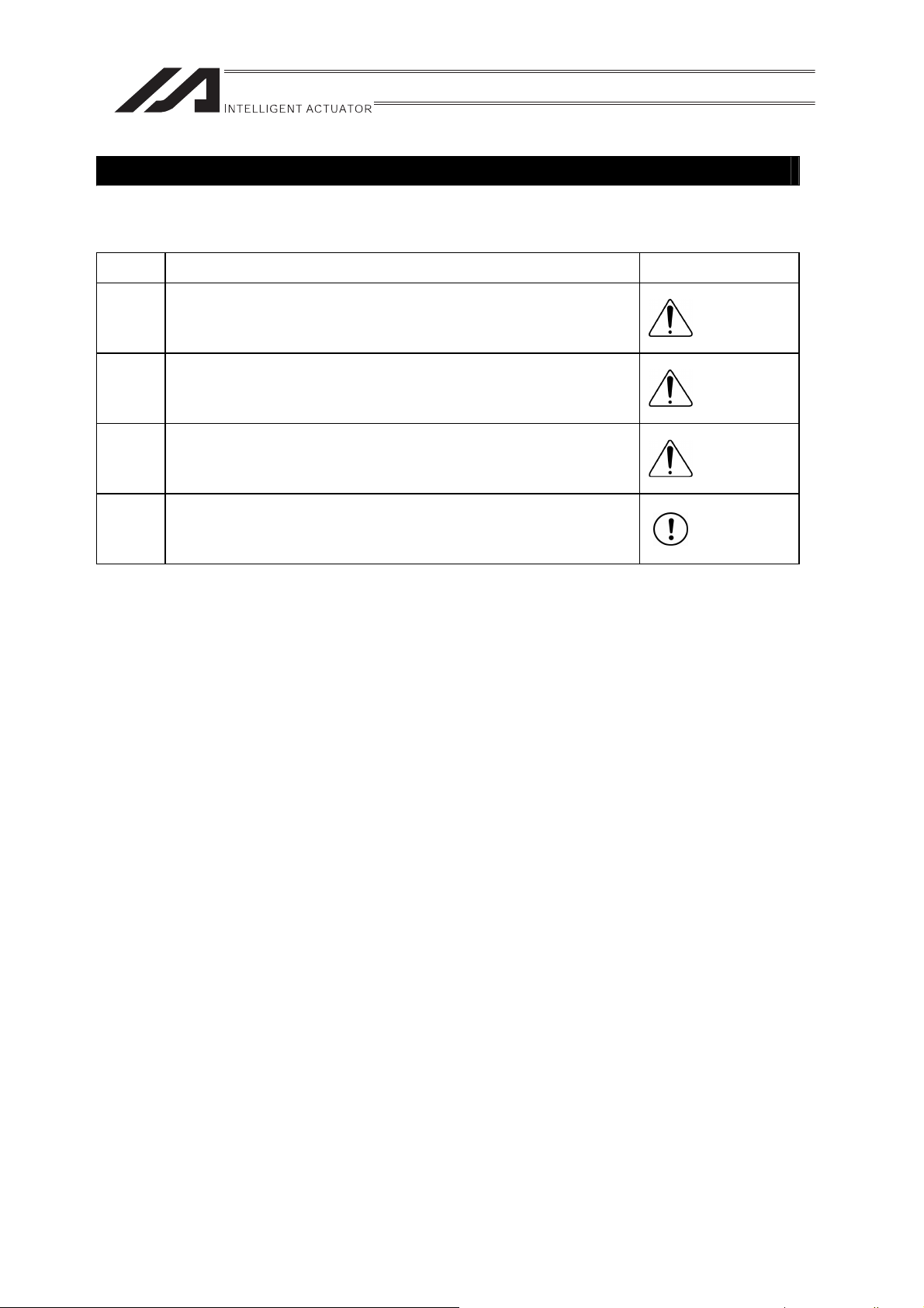
Alert Indication
The safety precautions are divided into “Danger”, “Warning”, “Caution” and “Notice” according to
the warning level, as follows, and described in the Operation Manual for each model.
Level Degree of Danger and Damage Symbol
Danger
Warning
Caution
Notice
This indicates an imminently hazardous situation which, if the
product is not handled correctly, will result in death or serious injury.
This indicates a potentially hazardous situation which, if the product
is not handled correctly, could result in death or serious injury.
This indicates a potentially hazardous situation which, if the product
is not handled correctly, may result in minor injury or property
damage.
This indicates lower possibility for the injury, but should be kept to
use this product properly.
Danger
Warning
Caution
Notice
7
Page 14

Caution in Handling
1. Do not have the settings of speed and acceleration/deceleration exceeding
the rated values.
An operation with speed and acceleration/deceleration beyond the allowable range may
cause an abnormal noise, vibration, malfunction or shortened life.
When having an interpolating operation for combined axes, set the smallest value among
the combined axes for each of speed and acceleration/deceleration settings.
2. Set the allowable load moment within the allowable range.
Use the product with the applied load moment within the allowable range.
An operation with the load beyond the allowable load moment may cause an abnormal
noise, vibration, malfunction or shortened life. If it is extreme, flaking may occur on the
guide.
3. Set the overhang length within the allowable range.
Have the overhang length of the load within the allowable range. The overhang length
above the allowable range may cause vibration or abnormal noise.
4. Back and forth operation in a short distance may cause wear of grease.
If the actuator is operated back and forth repeatedly over a distance of 30 mm or less, the oil
film created by the grease may be broken.
It is recommended to have 5 rounds of back and forth operation in a distance more than
50mm after every 5,000 to 10,000 rounds of the short distance operation. Keep using the
actuator with the grease worn out may cause malfunction. If it is extreme, flaking may occur
on the guide.
5. Ensure use of the product in the specified conditions, environments and
ranges.
Operation out of the specified conditions could cause a drop in performance or malfunction
of the product.
8
Page 15
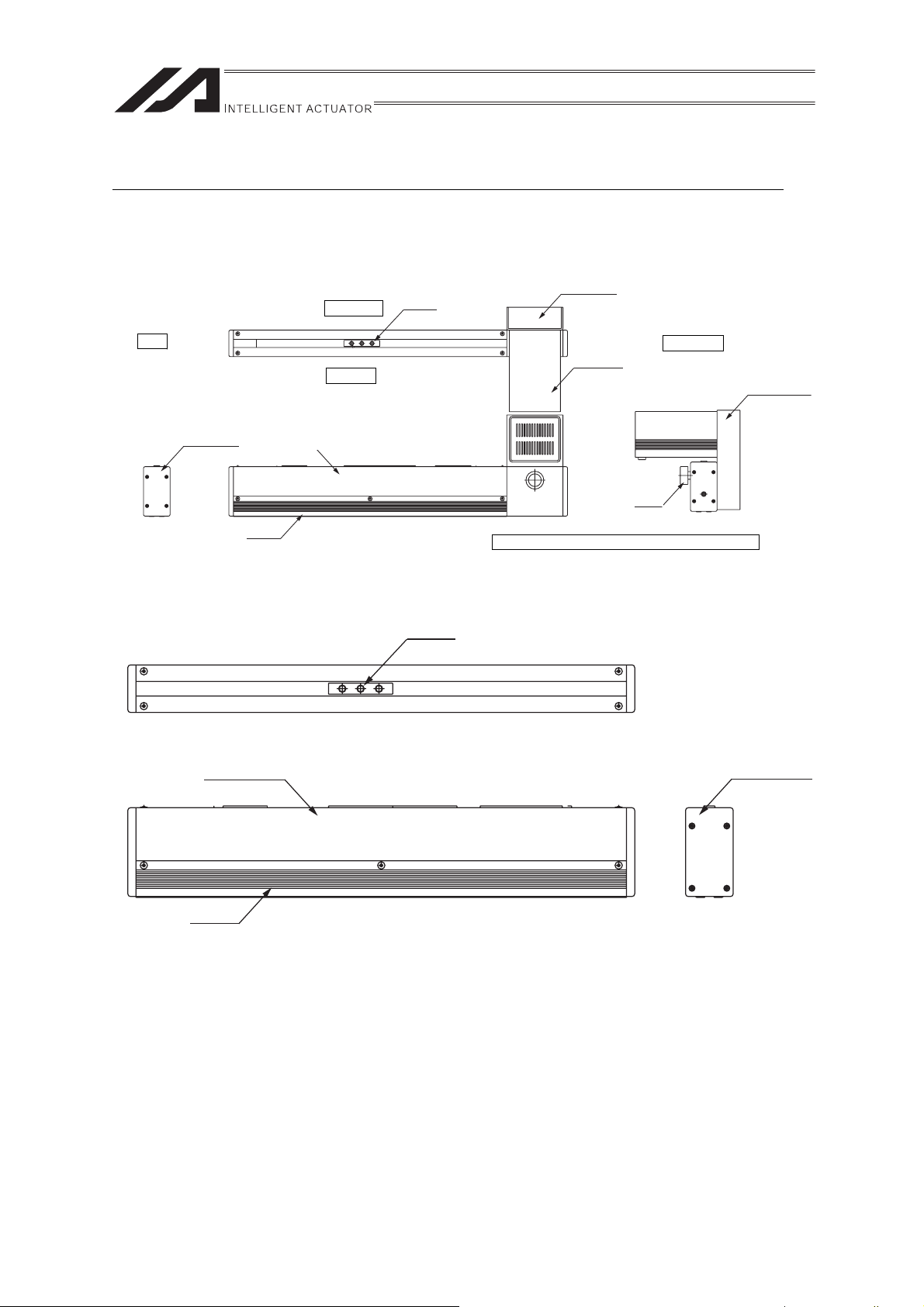
Names of the Parts
r
r
r
r
r
In this manual, the right and left sides of the actuator are expressed in the way it is placed
horizontally as shown in the figure below, and is looked at from the motor side.
[FS]
Right Side
Slide
Pulley Cove
Front
End Cove
[FS Guide Module]
Side Cover
Base
Side Cove
Base
Left Side
Motor Side
Motor Cove
Motor
Bracket
Knob
Motor location shown above is for standard type.
Slider
End Cover
9
Page 16

10
Page 17
1. Specifications Check
1.1 Product Check
The standard configuration of this product is comprised of the following parts.
See the component list for the details of the enclosed components. If you find any broken or
missing parts, contact your local IAI distributor.
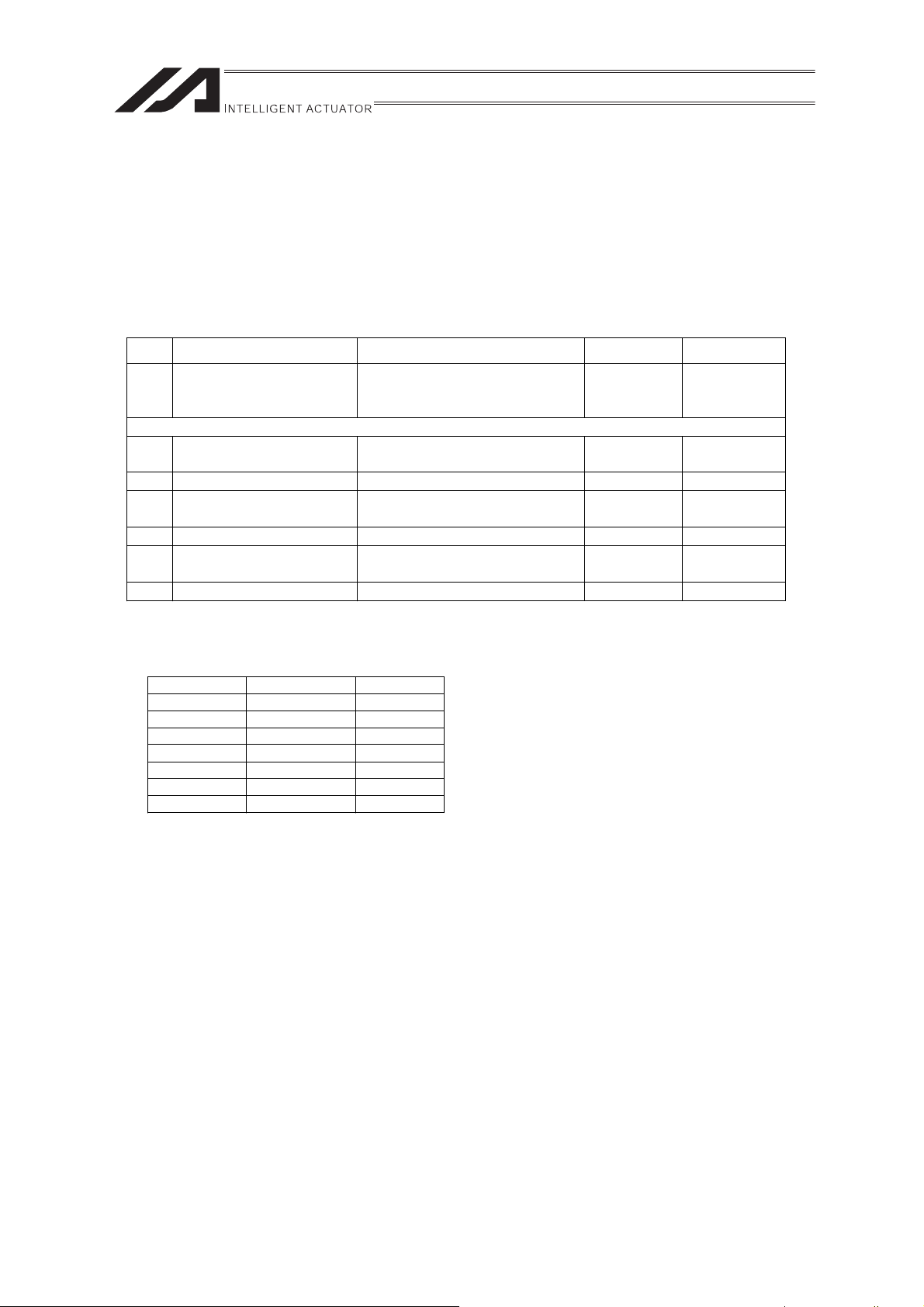
1.1.1 Parts
No. Part Name Model Quantity Remarks
Refer to “How to read the model
1 Main Body
Accessories
Motor • Encoder Cables
2
(Note 1)
3 In-House Made Seals 1 set
4 T-Nut
5 First Step Guide 1
Operation Manual
6
(CD/DVD)
7 Safety Guide 1
Note 1 The motor • encoder cables differ between the standard model and robot cable.
[Refer to 6 Motor • Encoder Cables.]
plate” and “How to read the
model No.”.
See the
1
1
table below
1
Enclosed in
FS
Quantity of T-nuts enclosed in FS series
Stroke NM, WM LM
to 1000 5 10
to 1500 6 12
to 2000 7 14
to 2500 8 16
to 3000 9 18
to 3500 10 20
to 4000 11 22
11
Page 18

1.1.2 Operation Manuals related to this product, which are contained in the
DVD.
Shown below is a list of the operation manuals for the controllers related to this product which is
recorded in Operation Manual (CD/DVD).
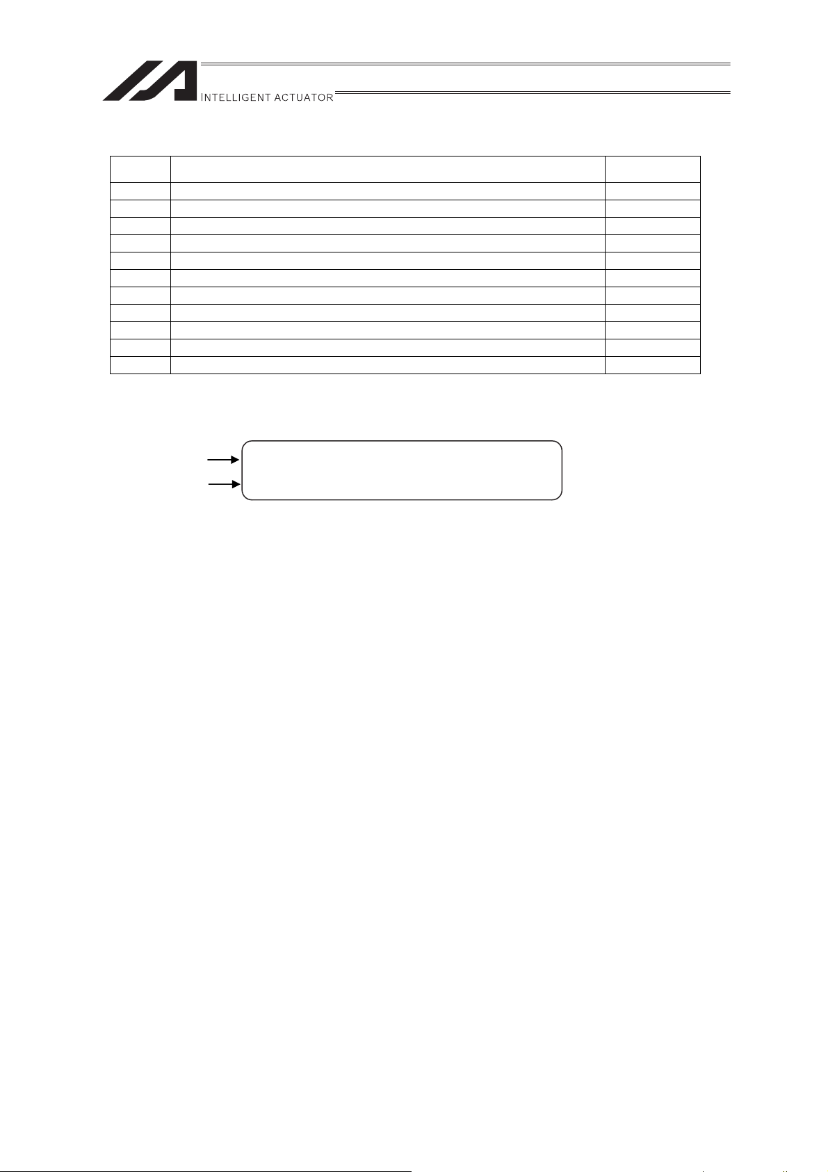
(1) XSEL-J/K Controller
No.
1 XSEL-J/K Controller Operation Manual ME0116
2 PC software IA-101-X-MW/IA-101-X-USBMW Operation Manual ME0154
3 Teaching pendant SEL-T/TD/TG Operation Manual ME0183
4 Teaching pendant IA-T-X/XD Operation Manual ME0160
5 DeviceNet Operation Manual ME0124
6 CC-Link Operation Manual ME0123
7 PROFIBUS Operation Manual ME0153
8 XSEL Ethernet Operation Manual ME0140
9 Multi-Point I/O Board Operation Manual ME0138
10 Multi-Point I/O Board Dedicated Terminal Board Operation Manual ME0139
(2) XSEL-P/Q Controller
No.
1 XSEL-P/Q Controller Operation Manual ME0148
2 XSEL-P/Q/PX/QX RC Gateway Function Operation Manual ME0188
3 PC software IA-101-X-MW/IA-101-X-USBMW Operation Manual ME0154
4 Teaching pendant SEL-T/TD/TG Operation Manual ME0183
5 Teaching pendant IA-T-X/XD Operation Manual ME0160
6 DeviceNet Operation Manual ME0124
7 CC-Link Operation Manual ME0123
8 PROFIBUS Operation Manual ME0153
Name Manual No.
Name Manual No.
(3) SSEL Controller
No.
1 SSEL Controller Operation Manual ME0157
2 PC software IA-101-X-MW/IA-101-X-USBMW Operation Manual ME0154
3 Teaching pendant SEL-T/TD/TG Operation Manual ME0183
4 Teaching pendant IA-T-X/XD Operation Manual ME0160
5 DeviceNet Operation Manual ME0124
6 CC-Link Operation Manual ME0123
7 PROFIBUS Operation Manual ME0153
Name Manual No.
12
Page 19
(4) SCON Controller
No.
1 SCON Controller Operation Manual ME0161
2 SCON-CA Controller Operation Manual ME0243
3 PC software RCM-101-MW/RCM-101-USB Operation Manual ME0155
4 Teaching pendant CON-T/TG Operation Manual ME0178
5 Touch panel teaching CON-PT/PD/PG Operation Manual ME0227
6 Simple teaching pendant RCM-E Operation Manual ME0174
7 Data setter RCM-P Operation Manual ME0175
8 Touch Panel Display RCM-PM-01 Operation Manual ME0182
9 DeviceNet Operation Manual ME0124
10 CC-Link Operation Manual ME0123
11 PROFIBUS Operation Manual ME0153
Name Manual No.
1.1.3 How to read the model plate
Model
Serial number
MODEL FS-11NM-I-60-200-T1-S-NM
SERIAL No.800061910 A1
MADE IN JAPAN
13
Page 20
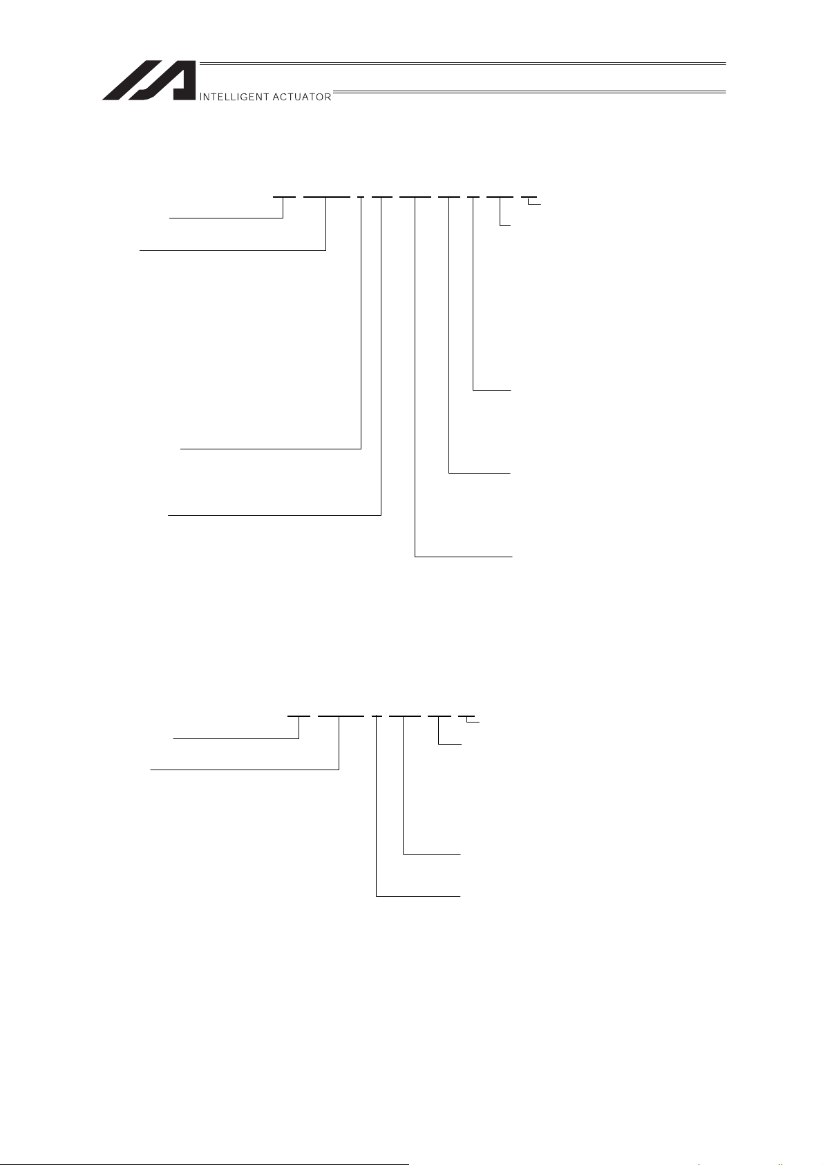
1.1.4 How to read the model No.
(Note1
)
(Note1
)
[FS]
FS
-11NM-I-60-200-T1-S-NM-**
Series Name
<Type>
11NM : Body width 40mm, Single Slider Type
12NM : Body width 40mm, Double Slider Type
11WM : Body width 52mm, Single Slider Type
12WM : Body width 52mm, Double Slider Type
11LM : Body width 75mm, High-Transportable Weight,
Single Slider Type
12LM : Body width 75mm, High-Transportable Weight,
Double Slider Type
11HM : Body width 75mm, High-speed,
Single Slider Type
12HM : Body width 75mm, High-speed,
Double Slider Type
<Encoder Type>
A : Absolute
I : Incremental
<Motor Type>
60 : 60W 200 : 200W
100 : 100W 400 : 400W
Identification for IAI use only
<Option>
D1 : Stainless Steel Sheet Type
(Slider length 200mm)
Corresponding to 12NM and 12WM only
D2 : Stainless Steel Sheet Type
(Slider length 300mm)
Corresponding to 12NM and 12WM only
NM : Reversed-home type
NQ : No motor equipped (motor cover equipped)
R : Motor on the Other Side
U : Motor Located on the Bottom
<Cable Length>
N : No cable
S : 3m
M : 5m
XƑƑ : Specified Length (Example: X07=7m)
<Applicable Controller>
T1 : XSEL-J/K
T2 : SCON
SSEL
XSEL-P/Q
<Stroke>
[Refer to 1.2 Specification]
Note 1 Identification for IAI use only: It may be displayed for IAI use. It is not a code to show
the model type.
[FS Guide Module]
FS-11NO-0-300-D1-**
Identification for IAI use only
Series Name
<Type>
11NO : Body width 40mm, Single Slider Type
12NO : Body width 40mm, Double Slider Type
11WO : Body width 52mm, Single Slider Type
12WO : Body width 52mm, Double Slider Type
11LO : Body width 75mm, Single Slider Type
12LO : Body width 75mm, Double Slider Type
<Option>
D1 : Stainless Steel Sheet Type
(Slider length 200mm)
Corresponding to 12NO and 12WO only
D2 : Stainless Steel Sheet Type
(Slider length 300mm)
Corresponding to 12NO and 12WO only
<Stroke>
[Refer to 1.2 Specification]
<Motor Type>
No motor equipped
Note 1 Identification for IAI use only: It may be displayed for IAI use. It is not a code to show
the model type.
14
Page 21
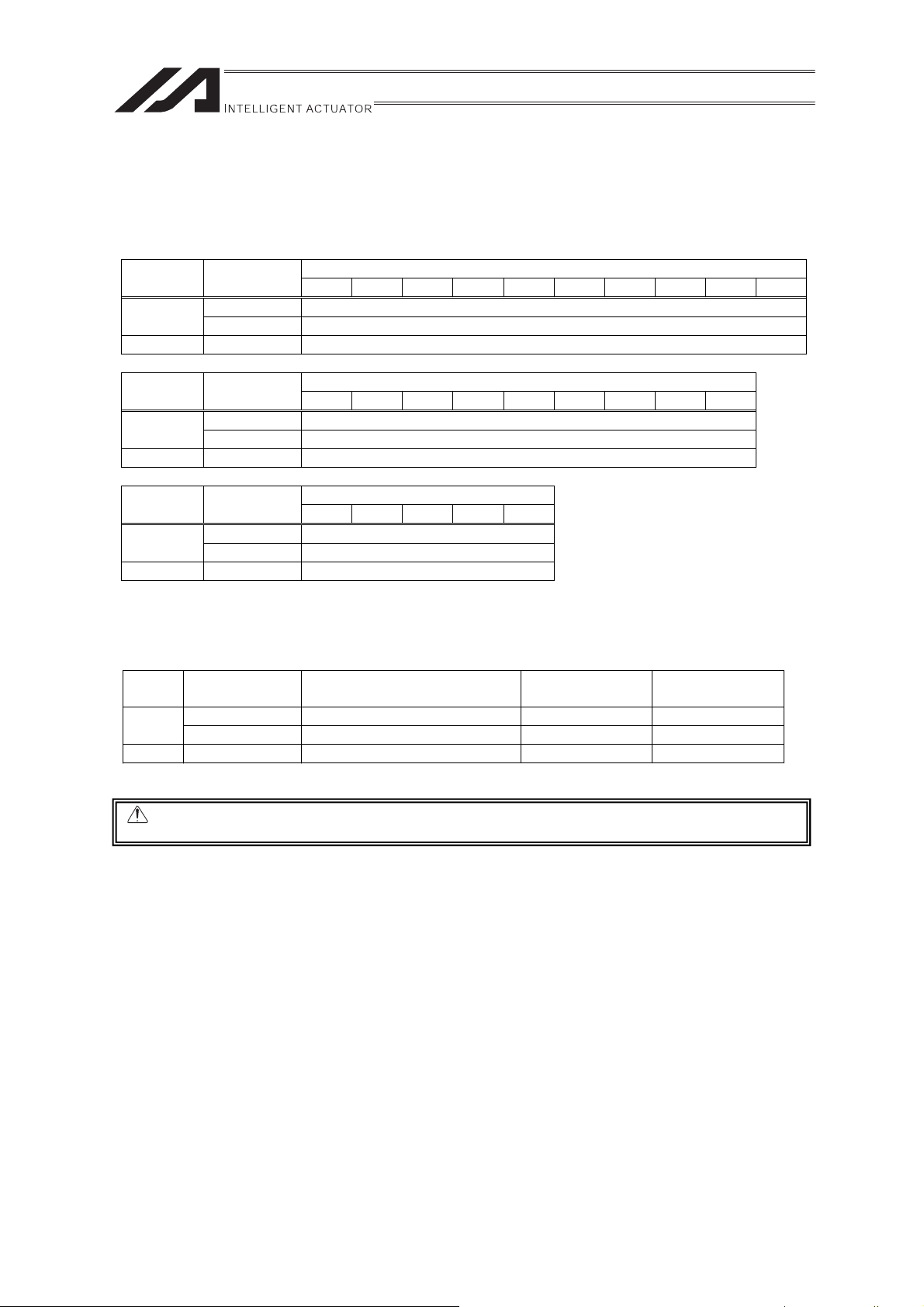
1.2 Specification
[1] Max. speed
There is a limit in the maximum speed of the actuators.
Restriction on Speed (Unit: mm/s)
Type
SA
MA 200 1 to 1750
Motor Type
[W]
60 1 to 1750
100 1 to 1750
200 300 400 500 600 700 800 900 1000 1100
Stroke [mm]
Type
SA
MA 200 1 to 1750
Type
SA
MA 200 1 to 1750
[2] Maximum acceleration and Transportable Weight
When the transported weight is low, the acceleration/deceleration can be increased.
Type Motor Type [W] Acceleration/deceleration [G]
SA
MA 200 0.3 20 85.7
Caution: Do not have the settings of acceleration/deceleration exceeding the rated values. It
Motor Type
[W]
60 1 to 1750
100 1 to 1750
Motor Type
[W]
60 -
100 -
60 0.3 5 25.8
100 0.3 10 43.0
may cause vibration, malfunction or shortened life.
1200 1300 1400 1500 1600 1700 1800 1900 2000
Stroke [mm]
2100 2200 2300 2400 2500
Stroke [mm]
Transportable
Weight [kg]
Rated Thrust [N]
15
Page 22

[3] Driving System and Position Detector
Type
SA
MA 200
[4] Positioning Accuracy
Positioning Repeatability ±0.08mm
The values shown above are the accuracy at the delivery from the factory. It does not include the
consideration of time-dependent change as it is used.
Motor Type
[W]
60
100
Item Specification
Lost Motion 0.1mm or less
No. of Encoder
Pulses
16384 Timing belt
Drive System
16
Page 23

1.3 Option
1.3.1 Reversed-home type
The home is set on the side opposite the motor.
The model code is indicated with an NM.
17
Page 24

1.4 Motor • Encoder Cables
1.4.1 Motor Cable (For XSEL-J/K/P/Q, SSEL and SCON)
CB-X-MAƑƑƑ
(Front View)
Controller Side
Wiring Color Signal No.
Green
0.75sq
White
Black
Red
PE
U
V
W
Mechanical Side
1
2
3
4
1
U
2
V
3
W
4
PE
Red
White
Black
Green
WiringColorSignalNo.
0.75sq
(Solderless)
(Front View)
1.4.2 Encoder Cable (For XSEL-J/K)
CB-X-PAƑƑƑ
(Front View) (Front View)
Controller Side Mechanical Side
Color No.
Wiring
0.15sq
(Solderless)
The shield is clamped to the hood
-
-
-
-
-
-
Blue
Orange
Black
Yellow
Green
Brown
Gray
Red
-
Signal
-
-
-
-
-
SD
SD
BAT+
BATVCC
GND
BK-
BK+
-
10
11
12
13
14
15
1
2
3
4
5
6
7
8
9
Ground wire and braided shield wires
No.
1
2
3
4
5
6
7
8
9
Signal
BAT+
BAT-
SD
SD
VCC
GND
FG
BKBK+
Color
Black
Yellow
Blue
Orange
Green
Brown
Drain
Gray
Red
Wiring
0.15sq
(Solderless)
18
Page 25
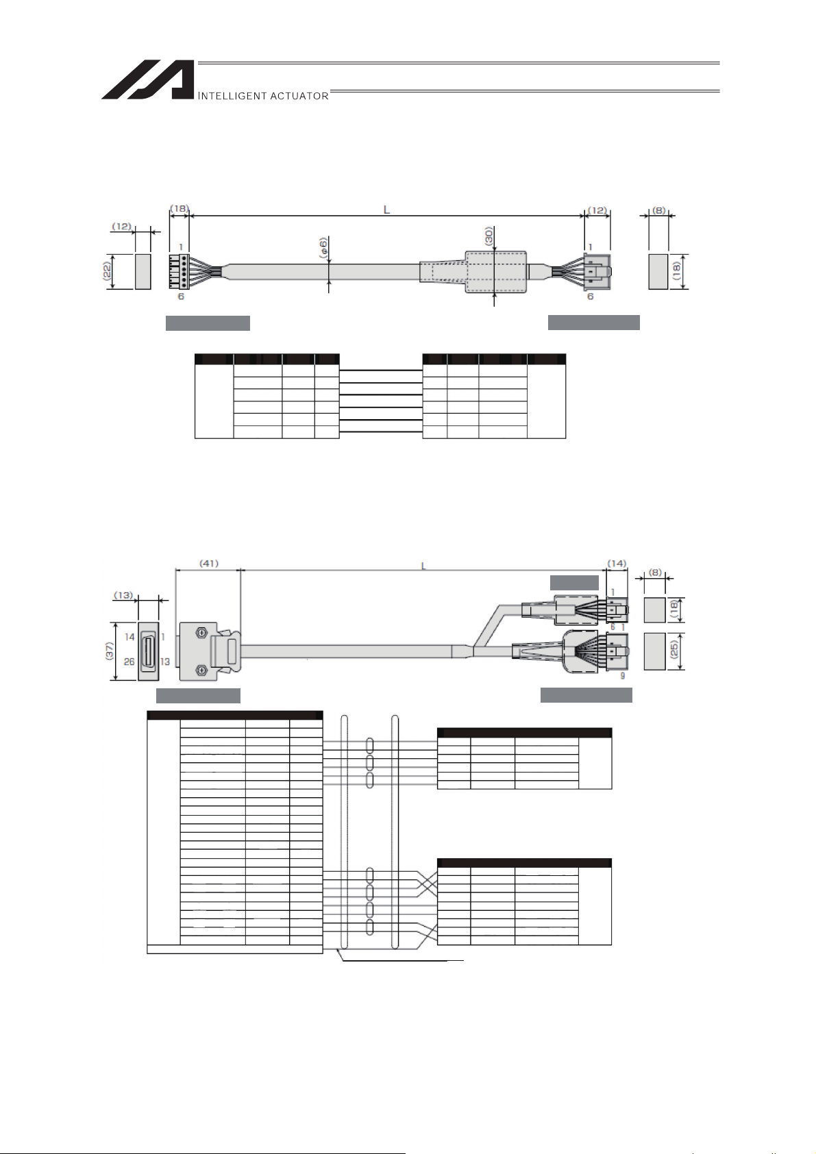
1.4.3 Limit Switch Cable (For XSEL-J/K)
CB-X-LCƑƑƑ
(Front View) (Front View)
Controller Side Mechanical Side
Wiring
Color
Sky Blue
Pink
Light Green
AWG24
Orange
Gray
1B/Sky Blue
Note) 1B indicates one black dot mark.
1.4.4 Encoder Cable
(For XSEL-P/Q, SSEL, SCON and LS equipped type connection)
CB-X1-PLAƑƑƑ
Controller Side Mechanical Side
Wiring Color
AWG26
(Soldered)
-
-
White/Blue
White/Yellow
White/Red
White/Black
White/Purple
White/Gray
-
-
-
-
-
-
-
-
-
Orange
Green
Purple
Gray
Red
Black
Blue
Yellow
-
The shield is clamped to the hood
Signal
-
-
E24V
0V
LS
CREEP
OT
RSV
-
-
A+
AB+
BZ+
Z-
SRD+
SRDBAT+
BAT-
VCC
GND
BKR-
BKR+
-
Signal
24VOUT
N
LS
CREEP
OT
RSV
No.
10
11
12
13
26
25
24
23
9
18
19
1
2
3
4
5
6
7
8
14
15
16
17
20
21
22
No.
6
5
4
3
2
1
Ground wire and braided shield wires
No.
1
2
3
4
5
6
Signal
24VOUT
CREEP
N
LS
OT
RSV
Color
Sky Blue
Pink
Light Green
Orange
Gray
1B/Sky Blue
Wiring
AWG24
(Solderless)
LS Side
Signal
No.
1
E24V
2
0V
3
LS
4
CREEP
5
OT
6
RSV
No.
Signal
1
BAT+
2
BAT-
3
SD
4
SD
5
VCC
6
GND
7
FG
8
BK-
9
BK+
(White/blue in cable color indicates the colors of line/insulator.)
Color
White/Blue
White/Yellow
White/Red
White/Black
White/Purple
White/Gray
Color
Purple
Gray
Orange
Green
Red
Black
Drain
Blue
Yellow
Wiring
AWG26
(Solderless)
Wiring
AWG26
(Solderless)
(Front View)
19
Page 26

2. Installation
2.1 Transportation
[1] Handling of the Robot
Pay attention to the following when carrying an actuator by itself.
(1) Handling of the Packed Product
Unless otherwise specified, the single axes at the delivery are packaged individually.
Please concern the handling of the unit so you would not hit or drop it while carrying.
x An operator should never attempt to carry a heavy package on their own.
x If the shipping box is to be left standing, it should be in a horizontal position.
x Do not step or sit on the package.
x Do not put any heavy thing that can deform the package, on it.
(2) Handling after Unpackaged
Do not attempt to hold the motor unit or cable when carrying the actuator, or pull the cables to
move the unit. Do not carry the actuator by holding the cable, or do not move it by pulling the
cable.
Make sure to hold the base area when handling the unpackaged actuator.
[2] Handling of Multi-Axes Type
Pay attention to the following when carrying the robot with the axes being attached.
(1) Handling of the Packed Product
If an order for the product was made with the axes attached, we would build the product in our
factory, conduct the delivery inspection, affix on a wooden pallet and cover with the frames to
deliver the product.
If the actuator to be attached is a slider type, the slider is fixed in the package so it would not
accidentally move. Also for the actuator of the combined unit, the end is fixed so it would not
widely shake by the external vibration.
x The package is not applied with any special treatment that enables it to resist an impact
caused by a drop or crash. Handle it with care. Also, please note that the frame would not
endure load on the top. Do not attempt to put load on it.
x When suspending the package using belts, pass the beltes from underneath the
reinforcement frames at the bottom of the base. When lifting with a forklift, also place the forks
underneath the base.
x Handle with care not to apply shock when putting it down.
20
Page 27

(2) Handling after Unpackaged
After unpackaged, handle the product that axes were attached in IAI factory following the
instructions below:
x Fix the sliders during transportation so they would not move accidently.
x Appropriately fix the end of the actuators if it is overhanging so it would not widely shake with
external vibration. If the actuator assembly is transported without the ends being secured, do
not apply an impact of 0.3G or more.
x In such cases as hanging the peripherals including the actuators with a belt, do not attempt to
attach the belt directly to the actuators and avoid the belt being touch the actuators.
x Apply appropriate shock-proof methods to the belt and set it so the base part receives the
load.
x For Y-axis, support the end with another belt to maintain the stable horizontal orientation. At
the same time, pay attention not to apply load to the screw cover.
x Do not attempt to apply load to the brackets, covers or connector box mounted on the main
body.
Also, avoid the cables being pinched or caused an excessive deformation.
[3] Handling of the Robot Mounted on Mechanical Equipment (System)
When peripheral devices were attached by the customer and the unit is to be carried, also follow
the instructions described in [5.2.2 handling in unpackaged condition] for appropriate handling.
21
Page 28

2.2 Installation and Storage • Preservation Environment
[1] Installation Environment
Do not use this product in the following environments.
It is generally the environment where a worker can work without any protection gear.
Also make sure to keep enough work space necessary for maintenance.
x Location exposed to radiant heat from a huge heat source such as the heat treatment
x Location where the surrounding air temperature exceeds the range of 0 to 40qC
x Location where condensation occurs due to abrupt temperature changes
x Location where relative humidity exceeds 85%RH
x Location exposed to direct sunlight
x Location exposed to corrosive gases or combustible gases
x Location exposed to significant amount of dust, salt or iron powder (Outside of an ordinary
assembly plant)
x Location where water, oil (includes oil mist and cutting fluid) or a chemical is splashed
x Location where the product main body receives vibration or hit impact
When using the product in any of the locations specified below, provide a sufficient shield.
x Place subject to electrostatic noise
x Location where exposed to the influence of strong electric or magnetic field
x Location where exposed to the influence of ultraviolet or radiant rays
[2] Storage • Preservation Environment
x The storage and preservation environment should comply with the same standards as those
for the installation environment. In particular, when the machine is to be stored for a long time,
pay close attention to environmental conditions so that no dew condensation forms.
x Unless specially specified, moisture absorbency protection is not included in the package
when the machine is delivered. In the case that the machine is to be stored and preserved in
an environment where dew condensation is anticipated, take the condensation preventive
measures from outside of the entire package, or directly after opening the package.
x For storage and preservation temperature, the machine withstands temperatures up to 60qC
for a short time, but in the case of the storage and preservation period of 1 month or more,
control the temperature to 50qC or less.
x Storage and preservation should be performed in the horizontal condition. In the case it is
stored in the packaged condition, follow the posture instruction if any displayed on the
package.
22
Page 29

2.3 How to Install
Shown below is how to install the actuators to the machinery equipment.
2.3.1 Posture of Actuator Installation
Shown below are the basic concepts for the product attachment.
Pay special attention when deciding how to install the product (Except with custom-order models).
{: Available U
Horizontal
Installation
Installation posture
Horizontal Vertical Sideway
: Precautions observing strictly ×: Not available
{
Vertic al
Installation
× ×
Sideway
Installation
Ceiling mount Installation
Stainless Steel
Sheet Type
If is not D1/D2
{
Ceiling Mount
Stainless Steel
Sheet Type
In the case of
D1/D2
×
23
Page 30

2.3.2 Installation
[1] Installation of Main Unit
x There is a T-groove on the back of the base. When installing the body, utilize this T-groove
and hold the body with the T-nut enclosed with the actuator.
x The base has to have a structure with sufficient rigidity to prevent oscillation.
x The surface where the actuator will be mounted should be a machined surface or that with an
accuracy equivalent to it, and the flatness should be 0.05mm or below.
Ensure a room for maintenance work.
(1) Mounting Procedure
x The bolts for mounting the actuator should be of a dimension suitable for the mounting holes
and slot.
x Use hexagonal bolts for the actuator mounting holes.
x We recommend high strength bolts of ISO-10.9 or higher.
x Make sure to have the effective length of screw engagement described below or more for the
tightening of a bolt and a female screw.
x When female screw is on steel ĺ thread length same as nominal diameter
x When female screw is on aluminum ĺ thread length 2 times longer than nominal
diameter
x When attaching the base to a mounting table, use washers made for high strength bolt if the
bolts is M8 or larger or if the bearing surface is made of aluminum. A washer is not necessary
for M6 or smaller bolts. Do not use a common spring washer.
x The recommended screw torque is given below.
Screw Nominal Diameter Tightening Torque
M6 7N•m [0.7kgf•m]
M8 26N•m [2.6kgf•m]
x Use the T-nuts provided by IAI. (Please see drawing below).
x If you require more than the number included, additional nuts are available for purchase.
x When mounting the actuator, select a bolt length so that the tip of the bolt does not touch the
bottom of the T-slot.
x If you are purchasing brackets with the actuator, please use the bolts, nuts and washers that
come with brackets.
24
Shape of T-nut
Page 31

[2] Load Attachment
x There are M8 tapped holes prepared on the slider. Fix the work piece to be carried.
x The way to affix follows the installation of the main unit.
x There is a restriction on the moment and overhang load length when attaching a load to the
slider.
Type
FS-11NM
FS-11NO
FS-12NM
FS-12NO
FS-11WM
FS-11WO
FS-12WM
FS-12WO
FS-11LM
FS-11LO
FS-11HM
FS-12LM
FS-12LO
FS-12HM
Allowable Load
Moment [N•m]
Ma: 2.9 (0.3)
Fig. 1) Single Slider
Mb: 2.9 (0.3)
Mc: 4.5 (0.46)
Fig. 2)
Double Slider
(when sliders are
joined together)
Ma: 20.5 (2.1)
Mb: 18.6 (1.9)
Mc: 9.1 (0.93)
Ma: 4.4 (0.45)
Fig. 1) Single Slider
Mb: 3.9 (0.4)
Mc: 5.8 (0.6)
Fig. 2)
Double Slider
(when sliders are
joined together)
Ma: 27.4 (2.8)
Mb: 25.4 (2.6)
Mc: 11.7 (1.2)
Ma: 8.8 (0.9)
Fig. 1) Single Slider
Mb: 7.8 (0.8)
Mc: 12.7 (1.3)
Fig. 2)
Double Slider
(when sliders are
joined together)
Ma: 51.9 (5.3)
Mb: 47.0 (4.8)
Mc: 25.4 (2.6)
Allowable dynamic moment directions
The allowable dynamic moment is the value assuming 20,000km.
Use of the actuator above the moment specification could cause
a drop of the life of the guide.
Moment Directions
Overhang Load Length [L]
Ma direction: 200 or less
Mb, Mc direction: 200 or less
Ma direction: 500 or less
Mb, Mc direction: 500 or less
Ma direction: 240 or less
Mb, Mc direction: 240 or less
Ma direction: 600 or less
Mb, Mc direction: 600 or less
Ma direction: 300 or less
Mb, Mc direction: 300 or less
Ma direction: 750 or less
Mb, Mc direction: 750 or less
Overhang Load Length
Use of the actuator with an overhang
above the allowable range for each model
could cause vibration or delay in the
operation time. Make sure to use the
actuator in the allowable range.
Single Slider (Fig. 1)
Double Slider (Fig. 2)
25
Page 32

3. Connection to the Controller
For the controller, only the dedicated controller manufactured by our company can be used.
Using other controllers may cause a problem such as burning the product, ignition or generating heat.
Use the dedicated cable enclosed in the package when connecting the actuator and the controller.
In this section, describes how to lay out the wirings for the single axis use.
In the single axis use, unless otherwise specified, the actuator will be delivered with a single axis
dedicated cable with 3m or 5m of its length enclosed in. Plug in the connector on the cable end directly
to the controller.
x Although we use cable that is resistant to bending fatigue, it is not robot cable.
Please avoid housing the cable in a wire duct with a small bending radius (we recommend R90 or
larger).
x In an application where the cable cannot be anchored, try to place the cable where it will sag only
under its own weight or use self-standing cable hose as large radius wire duct to limit the load on
the cable.
x Do not cut the cable to lengthen, shorten, or reconnect it.
If you wish to alter the cable, please consult with IAI before doing so.
26
Page 33

Warning: For wiring, please follow the warnings stated below. When constructing a system as
the machinery equipment, pay attention to the wiring and connection of each cable so
they are conducted properly. Not following them may cause not only a malfunction
such as cable breakage or connection failure, or an operation error, but also electric
shock or electric leakage, or may even cause a fire.
z Use dedicated cables of IAI indicated in this operation manual. Contact us if you wish to have a
change to the specifications of the dedicated cables.
z Make sure to turn the power OFF in the process of power line or cable connection or
disconnection.
z Do not attempt to cut a dedicated cable with connectors on both ends to extend, shorten or
re-joint it.
z Hold the dedicated cable to avoid mechanical force being applied to the terminals and
connectors.
z Use a cable pipe or duct to have an appropriate protection when there is a possibility of
mechanical damage on a dedicated cable.
z In case a dedicated cable is to be used at a moving part, make sure to lay out the cable without
applying any force to pull the connector or extreme bend on the cable. Do not attempt to use
the cable with a bending radius below the allowable value.
z Make certain that the connectors are plugged properly. Insufficient connection may cause an
operation error, thus it is extremely risky.
z Insufficient connection may cause an operation error, thus it is extremely risky.
z Pay attention to the cable layout so it would not hit peripherals during an operation. In case it
does, have an appropriate protection such as a cable track.
z When a cable is used hanging on the ceiling, prevent an environment that the cable swings
with acceleration or wind velocity.
z Make sure there is not too much friction inside the cable storage equipment.
z Do not apply radiated heat to power line or cables.
z Have a sufficient radius for bending to avoid stress being applied to one place.
Steel Strap
(Piano Wire)
Tie them up softly.
z Do not let the cable bend, kink or twist.
27
Page 34

z Do not pull the cable with a strong force.
z Do not let the cable receive a turning force at a single point.
z Do not pinch, drop a heavy object onto or cut the cable.
z When fixing the cable, provide a moderate slack and do not tension it too tight.
Do not use spiral tube in any
position where cables are bent
frequently.
z Separate the PIO line, communication line and power line from each other.
Arrange so that such lines are independently routed in the duct.
Power Line
I/O Line
(Flat Cable, etc.)
Duct
28
Page 35

z If using a cable track, make sure to use robot cables so the cables do not get twisted or
entangled inside the cable track or flexible tube, and also make the cables free to avoid the
cables getting tied. (Make sure the cables do not get pulled when being bent.)
z The occupied volume rate for the cables, etc., inside the cable track should be 60% or less.
Cable Track
Cable
29
Page 36

4. Setting the Home Position
[1] The Principle of the Homing Operation
The actuator performs homing in the following manner:
1) The moving direction is determined by the parameters set by the homing command.
2) It detects the mechanical end with the software in the home return operation.
The slider reverses direction when this end is reached and the place where the Z phase signal
3)
is detected becomes the reference point.
4) The slider travels further by an offset amount defined by the parameters and this position
becomes home.
(* The number of motor revolutions after the actuator hits the stopper until the Z-phase signal is
generated is already adjusted before the shipment.)
[2] Attaching Alignment Marks
x Use this mark by means of affixing to the product as the guide for the origin direction of the actuator,
as occasion demands.
[Use Examples]
1) Affixing it as the guide for the homing direction of the actuator
Affix it on to the slider.
Affix it on to the home side
of the base.
30
Page 37

2) Affixing it as the guide of the slider positions after movement
Affix it on to the slider.
Affix it on to the slider positions
after the movement.
3) Affixing it as the guide for the deviation check
Affix it on to the slider.
Affix it on to the base.
Affix two stickers each onto the slider and base while they are stopped at their origin positions.
x
31
Page 38

5. Maintenance Inspection
5.1 Inspection Items and Inspection Schedule
Have maintenance inspections following the intervals below.
The calculation is conducted under the condition that there are 8 working hours per day. Have
inspections more frequently if the operation frequency is high for night and day continuous operation,
etc.
At startup inspection
1 month after start of
operation
6 months after start
of operation
1 year after start of
operation
Every 6 months
thereafter
Every 1 year since
*1 If the actuator is operated back and forth repeatedly over a distance of 30 mm or less, the oil film
Visual Inspection Internal Check
{
{
{{
{{{
{
{{ {
Grease supply
*1
created by the grease may be broken. It is recommended to have 5 cycles of back and forth
operation in a distance more than 50mm after every 5,000 to 10,000 rounds of the short distance
operation. A layer of the grease will recover.
5.2 Visual inspection
For the visual inspection, check the appearance following items.
Main Body Looseness of attachment screws
Cables Scratches, proper connection of connectors
Overall Noise, vibration
5.3 Cleaning
x Please clean the external body on a regular basis.
x When cleaning, wipe with a soft cloth to remove dust and dirt.
x The base oil of the grease may come out on the surface of the actuator in some cases. Wipe it
away with soft cloth.
x There is a risk of dust getting in from a clearance. Do not blow compressed air strongly to the body.
x Do not apply petroleum solvent since it may damage the resin or painted surfaces.
x When extremely dirty, wipe it off firmly with cloth that a neutral detergent or alcohol is applied on.
32
Page 39

5.4 Inside Visual Inspection
Turn the power OFF, remove the side cover and do a visual check of the inside.
Confirm the inside condition with visual check.
Check to see if there is any dust or foreign objects inside the unit, and check the lubrication and
condition of the timing belt.
x Even if the grease is a brown color, the lubrication is fine as long as the travelling surface appears
to be wet.
x Check to see if there is any damage to the timing belt such as cracks in the teeth or in the section
behind the teeth.
(Note) The timing belt may generate a black powder. This is due to friction and is not unusual.
x The side cover can be removed with a hexagonal wrench.
If the grease is mixed with dust and dirty or has no shiny appearance, or if the grease has lost its
efficacy due to prolonged use, clean the applicable area and then replenish the grease.
After you finish inspection, tighten the mounting screws for side cover. The screw torque should be for a
cross-recessed head machine screw.
5.5 Internal Cleanup
x When cleaning, wipe with a soft cloth to remove dust and dirt.
x There is a risk of dust getting in from a clearance. Do not blow compressed air strongly to the body.
x Do not use oil type solvent, neutral detergent or alcohol.
33
Page 40

5.6 Grease Supply
[1] Applied Grease
The following grease is applied when the product is shipped out.
Idemitsu Kosan Co., Ltd. Daphne Eponex Grease No.2
Apart from above, there are equivalent sorts of grease sold in the market. For details contact a grease
supplier, provide the grease name shown above and ask them to select an equivalent.
Listed below are some equivalents for an example.
Showa Shell Sekiyu K. K. Alvania Grease No.2
Mobil Oil Mobilux 2
Warning: Do not attempt to apply fluorine grease. When mixed with lithium grease, not only
decrease the grease characteristics, but also may damage the actuator.
[2] How to apply grease
1) Remove the side cover.
2) With a grease gun, squirt grease into the grease nipple in the LM block to which the slider is
attached.
Insert enough grease so that some of it leaks out of the other side of the LM block.
3) Repeat this procedure for the other grease nipples on the LM block.
4) Move the slider back and forth several times by hand.
5) After this, wipe away the excess grease from the LM block.
6) Replace the side cover.
34
Page 41

5.7 Driving Belt Replacement
[Items required for the Replacement]
x Replacement Driving Belt
x Packing Tape
x 8mm Spanner Wrench
x Hexagon Wrench Set
x Push-Pull Gauge and Square
x Personal Computer or Teaching Pendant
x Tension Gauge (Tension of 10kgf or more available)
x Strong Thread (or Long Harness Belt)
[Replacement Operation Outline]
1) Loosen the tension adjusting bolt and replace the belt. Then, fasten the adjusting bolt until the
specified tension value is reached.
2) Perform the homing operation.
Loosen the deceleration belt, affix the slider at the point of 9mm from the mechanical end on the
home side, affix the motor shaft at the alignment mark, and then adjust the deceleration belt to the
specified tension.
3) Perform a home-return operation with using PC or a teaching pendant to check the amount of
misalignment from the original home position. In case there is misalignment, adjust the position
with Home-Return Offset
X-SEL Controllers, use Home Preset
for E-Con, P-Driver and SCON Controllers. For SSEL Controllers and
for adjustment.
Mechanical end
Home Position
Approx. 1mm
Establish setting with Home-Return Offset (E-Con, P-Driver and SCON) or Home
Preset (SSEL and X-SEL) in the parameter.
Z-phase ON position
Approx. 9mm
NM, WM type
At this position, the motor counter mark is aligned.
35
Page 42

[Procedure]
1) Detach the pulley cover and check the direction of motor shaft rotation when moving the slider
from the home position side to the mechanical end side. (the rotational direction differs depending
on the motor attachment position, thus checking is necessary.)
Detach the pulley cover.
(Use a hexagon wrench with the
distance to the opposite side of 1.5mm
.)
Confirm the motor shaft rotating direction.
2) Move the slider to a point where Z-phase to be the home turns ON.
The point should be 9mm away from the mechanical end for both home standard type and home
reversed type.
Put marks on the mechanical end and the point of Z-phase.
Put a mark on the mechanical end
where slider was pushed against.
9mm
Move the slider back away for 9mm from the
mechanical end.
Put another mark on this Z-phase point.
36
Page 43

3) Detach the side covers on both sides.
Remove the screws on the top and side.
(Use a hexagon wrench with the distance to the opposite side of 1.5mm.)
4) Detach the end cover on the side opposite the motor.
(Use a hexagon wrench with the distance to the opposite side of 2.5mm.)
37
Page 44

5) Loosen the locknut to make the tension adjustment bolts free.
(Use a spanner wrench of 8mm.)
Locknut
6) Loosen the tension adjustment bolt on the motor side.
(Use a hexagon wrench with the distance to the opposite side of 4mm.)
Tension Adjustment Bolt
7) Detach the end cover on the motor side.
(Use a hexagon wrench with the distance to the opposite side of 2.5mm.)
38
Page 45

8) Loosen the pulley fixing screws on the driving belt side.
(Use a hexagon wrench with the distance to the opposite side of 4mm.)
9) Remove the deceleration belt to make the pulley free.
Deceleration Belt
10) Detach the driving belt retainer plate.
(Use M4-sized hex wrench for NM. Use M5-sized hex wrench for WM.)
39
Page 46

11) Remove the driving belt.
Opposite Side of Motor
Motor Side
Pull out the driving belt in the
direction shown with an arrow.
Pull out the driving belt in the
direction shown with an arrow.
Tension
Adjuster
Motor Side
Pull out the tension adjuster
in the direction shown with an
arrow.
Pull the driving belt on the top and
the bottom in the direction shown
with the arrows to take it out
completely.
40
Page 47

12) Attach the replacement driving belt.
Motor Side
Tension
Adjuster
After putting the replacement
driving belt through the tension
adjuster, insert the belt on the top
and the bottom in the direction
shown with the arrows.
Opposite Side of Motor
1) Pull out the replacement
driving belt at the bottom
in the direction show with
the arrow.
2) Insert the replacement
driving belt on the top and
the bottom in the direction
shown with the arrows.
Insert the driving belt in the
direction shown with the arrow.
To the next page
41
Page 48

Motor Side
)
Tension
Adjuster
Tension
Adjustment Bolt
End Cover
Tension
Adjuster
Using the tension adjustment
bolt, attach the end cover to
the tension adjuster.
Push in the tension adjuster
completely in the direction
shown with the arrow.
(Use a hexagon wrench with the
distance to the opposite side of
4mm.
Attach the end cover.
(Use a hexagon wrench with the
distance to the opposite side of
2.5mm.)
Pull the replacement driving
belt to align it with the teeth
on the attachment part.
Teeth on
Attachment Part
(Note) Have the driving belt to make its ends adjusted in the center of the attachment
teeth part. Cut the driving belt if it is too long.
42
Page 49

13) Attach the driving belt retainer plate.
(Use M4-sized hex wrench for NM. Use M5-sized hex wrench for WM.)
14) Adjust the belt to the specified tension.
• Set the slider at the point 400mm from the center of the pulley.
• Set a push-pull gauge at the point 200mm from the center of the pulley.
Adjust the tension of the belt with the tension adjustment bolt to make the clearance between the
inside of the belt and the top surface of LM guide 0mm when applying the specified load.
Load Specifications
NM 3kgf
WM 7kgf
Push-pull Gauge
Tension Adjustment Bolt
Adjust the tension of
the belt to make the
clearance 0mm when
applying the specified
load.
200mm
400mm
43
Page 50

15) Tighten the locknut to make the tension adjustment bolts fixed.
(Use a spanner wrench of 8mm.)
Locknut
16) Make an adjustment to reconstruct the home position.
1. Attach the cover on one side with the marking and move the slider to a position where the
Z-phase to be the home turns ON. It is the point 9mm away from the mechanical end for both
standard home type and reversed home type.
9mm
2. On the motor side, it should be the position of the first alignment marks.
Align the marks if they are misaligned.
Match the alignment marks.
44
Page 51

3. Hang the deceleration belt while holding the pulleys so both of them would not move during the
work.
Deceleration Belt
4. Put a robust rope in a ring shape (or a long cable band) around the motor cover, and pull it on a
tension gauge.
While it is pulled up with the specified tensile force, tighten the screws at four points.
(Use a hexagon wrench with the distance to the opposite side of 4mm.)
(Pay attention to the slider and motor shaft so they would not move while in the work.)
Specified Tensile Force
NM 5kgf
WM 10kgf
Pull up with specified tensile force.
45
Page 52

17) Attach the slider cover on the other side.
Tighten the fixing screws on the top and side surfaces.
(Use a hexagon wrench with the distance to the opposite side of 1.5mm.)
18) Put the end cover on the opposite side of the motor.
(Use a hexagon wrench with the distance to the opposite side of 2.5mm.)
46
Page 53

19) Hang the hook on the bottom of the pulley cover to the corner catch, and tighten screws on the
top.
(Use a hexagon wrench with the distance to the opposite side of 1.5mm.)
Hang on corner catch.
20) Execute the home-return operation on the PC (PC software) or a teaching pendant. (for the
absolute encoder, the absolute reset is required.)
Check the amount of misalignment to the original home position.
If there is a misalignment, fine-tune the home-return offset
SCON Controllers. For P-Driver Controller, fine-tune the home-return offset
Data No. 17. For SSEL Controller and X-SEL Controller, use Home Preset
Parameter No. 12 for adjustment.
in Parameter No. 22 for E-Con and
in Position Control
in Each Axis
47
Page 54

5.8 How to Replace the Deceleration Belt
[Items required for the Replacement]
x Replacement Driving Belt
x
Hexagon Wrench Set
x Measure
x Personal Computer or Teaching Pendant
x Tension Gauge (Tension of 10kgf or more available)
x Strong Thread (or Long Harness Belt)
[Replacement Operation Outline]
1) Loosen the pulley fixing screw on the driving belt side to take off the belt.
2) Perform the homing operation.
Loosen the deceleration belt, affix the slider at the point of 9mm from the mechanical end on the
home side, and then affix the motor shaft at the alignment mark.
3) Put the new replacement deceleration belt and tighten the pulley fixing screw on the driving belt
side up to get the specified tension.
4) Perform a home-return operation with using PC or a teaching pendant to check the amount of
misalignment from the original home position. In case there is misalignment, adjust the position
with Home-Return Offset
X-SEL Controllers, use Home Preset
Home Position
for E-Con, P-Driver and SCON Controllers. For SSEL Controllers and
for adjustment.
Mechanical end
Z-phase ON position
Approx. 1mm
At this position, the motor counter mark is aligned.
Establish setting with Home-Return Offset (E-Con, P-Driver and SCON) or Home
Preset (SSEL and X-SEL) in the parameter.
Approx. 9mm
NM, WM type
48
Page 55

[Procedure]
1) Detach the pulley cover and check the direction of motor shaft rotation when moving the slider from
the home position side to the mechanical end side. (the rotational direction differs depending on the
motor attachment position, thus checking is necessary.)
Detach the pulley cover.
(Use a hexagon wrench with the
distance to the opposite side of 1.5 mm.)
Confirm the motor shaft rotating direction.
2) Move the slider to a point where Z-phase to be the home turns ON.
The point should be 9mm away from the mechanical end for both home standard type and home
reversed type.
Put marks on the mechanical end and the point of Z-phase.
Put a mark on the mechanical end
where slider was pushed against.
9mm
Move the slider back away for 9mm from the
mechanical end.
Put another mark on this Z-phase point.
49
Page 56

3) Loosen the pulley fixing screws on the driving belt side.
(Use a hexagon wrench with the distance to the opposite side of 4mm.)
4) Remove the deceleration belt to make the pulley free.
Deceleration Belt
50
Page 57

5) After attaching the new replacement deceleration belt, make an adjustment to reconstruct the
home position.
1. Attach the cover on one side with the marking and move the slider to a position where the
Z-phase to be the home turns ON. It is the point 9mm away from the mechanical end for both
standard home type and reversed home type.
9mm
2. On the motor side, it should be the position of the first alignment marks.
Align the marks if they are misaligned.
Match the alignment marks.
3. Hang the deceleration belt while holding the pulleys so both of them would not move during the
work.
Replacement
Deceleration Belt
51
Page 58

4. Put a robust rope in a ring shape (or a long cable band) around the motor cover, and pull it on a
tension gauge.
While it is pulled up with the specified tensile force, tighten the screws at four points.
(Use a hexagon wrench with the distance to the opposite side of 4mm.)
(Pay attention to the slider and motor shaft so they would not move while in the work.)
Specified Tensile Force
NM 5kgf
WM 10kgf
Pull up with specified tensile force.
52
Page 59

6) Hang the hook on the bottom of the pulley cover to the corner catch, and tighten screws on the top.
(Use a hexagon wrench with the distance to the opposite side of 1.5mm.)
Hang on corner catch.
7) Execute the home-return operation on the PC (PC software) or a teaching pendant. (for the
absolute encoder, the absolute reset is required.)
Check the amount of misalignment to the original home position.
If there is a misalignment, fine-tune the home-return offset
SCON Controllers. For P-Driver Controller, fine-tune the home-return offset
No. 17. For SSEL Controller and X-SEL Controller, use Home Preset
12 for adjustment.
in Parameter No. 22 for E-Con and
in Position Control Data
in Each Axis Parameter No.
53
Page 60

5.9 Motor Replacement
[Items required for the Replacement]
x Replacement Motor (Refer to the picture at right)
(Confirm that the counter mark is attached)
x Hexagon Wrench Set
x Phillips Screwdriver
x Measure
x Personal Computer or Teaching Pendant
x Tension Gauge (Tension of 10kgf or more available)
x Strong Thread (or Long Harness Belt)
[Replacement Operation Outline]
1) Loosen the pulley fixing screw on the driving belt side to detach the deceleration belt, and replace
the motor.
2) Perform the homing operation.
Loosen the deceleration belt, affix the slider at the point of 9mm from the mechanical end on the
home side, and then affix the motor shaft at the alignment mark.
3) Put the deceleration belt and tighten the pulley fixing screw on the driving belt side up to get the
specified tension.
4) Perform a home-return operation with using PC or a teaching pendant to check the amount of
misalignment from the original home position. In case there is misalignment, adjust the position
with Home-Return Offset
X-SEL Controllers, use Home Preset
for E-Con, P-Driver and SCON Controllers. For SSEL Controllers and
for adjustment.
Mechanical end
Home Position
Approx. 1mm
Establish setting with Home-Return Offset (E-Con, P-Driver and SCON) or Home
Preset (SSEL and X-SEL) in the parameter.
Z-phase ON position
Approx. 9mm
NM, WM type
At this position, the motor counter mark is aligned.
54
Page 61

[Procedure]
p
1) Detach the pulley cover and check the direction of motor shaft rotation when moving the slider from
the home position side to the mechanical end side. (the rotational direction differs depending on the
motor attachment position, thus checking is necessary.)
Detach the pulley cover.
(Use a hexagon wrench with the
distance to the opposite side of 1.5mm.)
Confirm the motor shaft rotating direction.
2) Move the slider to a point where Z-phase to be the home turns ON.
The point should be 9mm away from the mechanical end for both home standard type and home
reversed type.
Put marks on the mechanical end and the point of Z-phase.
Put a mark on the mechanical end
where slider was pushed against.
9mm
Move the slider back away for 9mm from the
mechanical end.
Put another mark on this Z-
hase point.
55
Page 62

3) Loosen the pulley fixing screws on the driving belt side.
(Use a hexagon wrench with the distance to the opposite side of 4mm.)
4) Remove the deceleration belt to make the pulley free.
Deceleration Belt
56
Page 63

5) Detach the lid on the motor cover.
(Use a hexagon wrench with the distance to the opposite side of 1.5mm.)
6) Unplug the motor cables and encoder cables on the motor side and actuator side.
7) Detach the FG cable. (Use a Phillips screwdriver.)
FG
Joint Cable
57
Page 64

8) Detach the motor cover.
(Use a hexagon wrench with the distance to the opposite side of 2.5mm.)
9) Detach the motor.
(Use a hexagon wrench with the distance to the opposite side of 2mm.)
Check the position of the alignment marks before taking off the motor.
Check the position (angle) of
the alignment marks.
58
Page 65

10) Insert the replacement motor while matching the position (angle) of the alignment marks, and then
attach the motor.
(Use a hexagon wrench with the distance to the opposite side of 2mm.)
Check the position (angle) of
the alignment marks.
Replacement
Motor
11) Attach the motor cover.
(Use a hexagon wrench with the distance to the opposite side of 2.5mm.)
Motor Cover
59
Page 66

12) Attach the FG cable. (Use a Phillips screwdriver.)
13) Join the motor cables and encoder cables on the motor side and actuator side.
FG
Joint Cable
14) Attach the lid on the motor cover.
(Use a hexagon wrench with the distance to the opposite side of 1.5mm.)
60
Page 67

15) After attaching the new replacement deceleration belt, make an adjustment to reconstruct the
home position.
1. Attach the cover on one side with the marking and move the slider to a position where the
Z-phase to be the home turns ON. It is the point 9mm away from the mechanical end for both
standard home type and reversed home type.
9mm
2. On the motor side, it should be the position of the first alignment marks.
Align the marks if they are misaligned.
Match the alignment marks.
3. Hang the deceleration belt while holding the pulleys so both of them would not move during the
work.
Replacement
Deceleration Belt
61
Page 68

4. Put a robust rope in a ring shape (or a long cable band) around the motor cover, and pull it on a
tension gauge.
While it is pulled up with the specified tensile force, tighten the screws at four points.
(Use a hexagon wrench with the distance to the opposite side of 4mm.)
(Pay attention to the slider and motor shaft so they would not move while in the work.)
Specified Tensile Force
NM 5kgf
WM 10kgf
Pull up with specified tensile force.
62
Page 69

16) Hang the hook on the bottom of the pulley cover to the corner catch, and tighten screws on the top.
(Use a hexagon wrench with the distance to the opposite side of 1.5mm.)
Hang on corner catch.
17) Execute the home-return operation on the PC (PC software) or a teaching pendant. (for the
absolute encoder, the absolute reset is required.)
Check the amount of misalignment to the original home position.
If there is a misalignment, fine-tune the home-return offset
SCON Controllers. For P-Driver Controller, fine-tune the home-return offset
No. 17. For SSEL Controller and X-SEL Controller, use Home Preset
12 for adjustment.
in Parameter No. 22 for E-Con and
in Position Control Data
in Each Axis Parameter No.
63
Page 70

6. External Dimensions
6.1 FS-11NM-60 (Single Slider), FS-12NM-60 (Double Slider)
11NM (Single Slider)
10 20 106020
M8, Depth 10
SE: Stroke end
ME: Mechanical end
*1 The number in the brackets is the dimension for 12NM.
40
12
80
8
22
SE
86
10
ME
28
C
A
D
B
T-slot
60 (120 *1)
Home
70
10
ME
88
(300)
80
8
21
12NM (Double Slider)
Free Slider
70
84
35
Cable Joint Connector
60
20
20
10 10
190
150
59
130
±
20.2
±
10.2
28
Driving Slider
M8, Depth 10
40
60
0.2
7
6
0.2
152
4
156
T-slot Dimension
FS-11NM-60 (Single Slider)
Stroke 300 400 500 600 700 800 900 1000
A 604 704 804 904 1004 1104 1204 1304
B 480 580 680 780 880 980 1080 1180
C 300 400 500 600 700 800 900 1000
D 360 460 560 660 760 860 960 1060
Weight
[kg]
5.0 5.4 5.8 6.2 6.6 7.0 7.4 7.8
FS-12NM-60 (Double Slider)
Stroke 300 400 500 600 700 800 900 1000
A 704 804 904 1004 1104 1204 1304 1404
B 580 680 780 880 980 1080 1180 1280
C 340 440 540 640 740 840 940 1040
D 460 560 660 760 860 960 1060 1160
Weight
[kg]
5.7 6.0 6.5 6.9 7.3 7.7 8.1 8.5
64
Page 71

6.2 FS-11NM-100 (Single Slider), FS-12NM-100 (Double Slider)
11NM (Single Slider)
10 20 106020
M8, Depth 10
SE: Stroke end
ME: Mechanical end
*1 The number in the brackets is the dimension for 12NM.
40
12
80
8
22
SE
86
10
ME
28
C
A
D
B
T-slot
60 (120 *1)
Home
70
10
ME
88
80
8
21
12NM (Double Slider)
Free Slider
70
84
(300)
Cable Joint Connector
10 10
165
35
59
145
205
20.2
10.2
60
20
20
±
±
28
Driving Slider
M8, Depth 10
40
60
0.2
7
6
0.2
152
4
156
T-slot Dimension
FS-11NM-100 (Single Slider)
Stroke 300 400 500 600 700 800 900 1000
A 604 704 804 904 1004 1104 1204 1304
B 480 580 680 780 880 980 1080 1180
C 300 400 500 600 700 800 900 1000
D 360 460 560 660 760 860 960 1060
Weight
[kg]
5.0 5.4 5.8 6.2 6.6 7.0 7.4 7.8
FS-12NM-100 (Double Slider)
Stroke 300 400 500 600 700 800 900 1000
A 704 804 904 1004 1104 1204 1304 1404
B 580 680 780 880 980 1080 1180 1280
C 340 440 540 640 740 840 940 1040
D 460 560 660 760 860 960 1060 1160
Weight
[kg]
5.7 6.0 6.5 6.9 7.3 7.7 8.1 8.5
65
Page 72

6.3 FS-11NO-0 (Single Slider), FS-12NO-0 (Double Slider)
11NO (Single Slider)
60
20
20
10
SE: Stroke end
ME: Mechanical end
40
12
8
80
SE
78
10
ME
M8, Depth 10
C
10
*1 The number in the brackets is the dimension for 12NO.
A
D
B
T-slot
60 (120 *1)
Home
8
70
10
ME
12NO (Double Slider)
10 10
Free Slider
±
20.2
±
10.2
28
60
20
0.2
0.2
20
Free Slider
M8, Depth 10
67
T-slot Dimension
FS-11NO-0 (Single Slider)
Stroke 300 400 500 600 700 800 900 1000
A 524 624 724 824 924 1024 1124 1224
B 508 608 708 808 908 1008 1108 1208
C 300 400 500 600 700 800 900 1000
D 360 460 560 660 760 860 960 1060
Weight
[kg]
2.4 2.8 3.2 3.6 4.1 4.4 4.8 5.2
FS-12NO-0 (Double Slider)
Stroke 300 400 500 600 700 800 900 1000
A 624 724 824 924 1024 1124 1224 1324
B 608 708 808 908 1008 1108 1208 1308
C 340 440 540 640 740 840 940 1040
D 460 560 660 760 860 960 1060 1160
Weight
[kg]
3.1 3.5 3.9 4.3 4.8 5.1 5.5 5.9
66
Page 73

6.4 FS-11WM-100 (Single Slider), FS-12WM-100 (Double Slider)
11WM (Single Slider)
70
20 15
15 20
M8, Depth 14
SE: Stroke end
ME: Mechanical end
*1 The number in the brackets is the dimension for 12WM.
SE
845
103
ME
10
52
12
100
21
A
D
C
T-slot
B
70 (140 *1)
Home
ME
70
10
118
8110
12WM (Double Slider)
Free Slider Driving Slider
90
107
(300)
21
70
20
20
15 15
M8, Depth 14
205
160
35
71.5
134
Cable Joint Connector
20.2
10.2
45
195
4.5
71
±0.2
67
±0.2
28
T-slot Dimension
FS-11WM-100 (Single Slider)
Stroke 300 400 600 800 1000 1500 2000 2500
A 661 761 961 1161 1361 1861 2361 2861
B 490 590 790 990 1190 1690 2190 2690
C 300 400 600 800 1000 1500 2000 2500
D 370 470 670 870 1070 1570 2070 2570
Weight
[kg]
8.7 9.3 10.5 11.7 12.9 15.9 18.9 21.9
FS-12WM-100 (Double Slider)
Stroke 300 400 500 600 700 800 900 1000
A 624 724 824 924 1024 1124 1224 1324
B 608 708 808 908 1008 1108 1208 1308
C 340 440 540 640 740 840 940 1040
D 460 560 660 760 860 960 1060 1160
Weight
[kg]
3.1 3.5 3.9 4.3 4.8 5.1 5.5 5.9
67
Page 74

6.5 FS-11WM-200 (Single Slider), FS-12WM-200 (Double Slider)
11WM (Single Slider)
70
20 15
15 20
M8, Depth 14
SE: Stroke end
ME: Mechanical end
*1 The number in the brackets is the dimension for 12WM.
SE
845
103
ME
10
52
12
100
21
A
D
C
T-slot
B
70 (140 *1)
Home
ME
70
10
118
8110
12WM (Double Slider)
Free Slider Driving Slider
90
107
(300)
21
70
20
20
15 15
M8, Depth 14
205
160
35
71.5
134
Cable Joint Connector
20.2
10.2
T-slot Dimension
45
195
4.5
71
±0.2
67
±0.2
28
FS-11WM-200 (Single Slider)
Stroke 300 400 600 800 1000 1500 2000 2500
A 661 761 961 1161 1361 1861 2361 2861
B 490 590 790 990 1190 1690 2190 2690
C 300 400 600 800 1000 1500 2000 2500
D 370 470 670 870 1070 1570 2070 2570
Weight
[kg]
9.8 10.4 11.6 12.8 14.0 17.0 20.0 23.0
FS-12WM-200 (Double Slider)
Stroke 300 400 600 800 1000 1500 2000 2500
A 761 861 1061 1261 1461 1961 2461 2961
B 590 690 890 1090 1290 1790 2290 2790
C 330 430 630 830 1030 1530 2030 2530
D 470 570 770 970 1170 1670 2170 2670
Weight
[kg]
11.0 11.6 12.8 14.0 15.2 18.2 21.2 24.2
68
Page 75

6.6 FS-11WO-0 (Single Slider), FS-12WO-0 (Double Slider)
11WO (Single Slider)
70
20 15
15 20
SE: Stroke end
ME: Mechanical end
SE
52
12
100
103
10
ME
8
M8, Depth 14
*1 The number in the brackets is the dimension for 12WO.
A
D
C
B
T-slot
70 (140 *1)
Home
ME
8
70
10
12WO (Double Slider)
15 15
Free Slider
±0.2
20.2
±0.2
10.2
28
T-slot Dimension
70
20
20
M8, Depth 14
67
Free Slider
FS-11WO-0 (Single Slider)
Stroke300 400 600 800 1000 1500 2000 2500
A 551 651 851 1051 1251 1751 2251 2751
B 535 635 835 1035 1235 1735 2235 2735
C 300 400 600 800 1000 1500 2000 2500
D 370 470 670 870 1070 1570 2070 2570
Weight
[kg]
4.9 5.6 6.7 8.3 9.6 12.9 16.3 19.6
FS-12WO-0 (Double Slider)
Stroke300 400 600 800 1000 1500 2000 2500
A 651 751 951 1151 1351 1851 2351 2851
B 635 735 935 1135 1335 1835 2335 2835
C 330 430 630 830 1030 1530 2030 2530
D 470 570 770 970 1170 1670 2170 2670
Weight
[kg]
5.6 6.2 7.6 8.9 10.2 13.6 16.9 20.3
69
Page 76

6.7 FS-11LM-400 (Single Slider), FS-12LM-400 (Double Slider)
75
25
1332135
40±0.3
67
10.2±0.3
20.2±0.3
24
T-slot Dimension
11LM (Single Slider)
85
15 15
2020
5-M8, Depth 12
*1 The number in the brackets is the dimension for 12LM.
A
SE
ME
54 B 150 1010
61
T-Slot
C: Storke
85 (170 *1)
SE
120184 D
2020
ME
160
12LM (Double Slider)
85
209.4
160
98
15
2020
10-M8, Depth 12
49.4
221
22
15
Free Slider Driving Slider
90
φ35
(300)
23
122.5 86.9
Cable Joint Connector
SE: Stroke end
61
ME: Mechanical end
243
FS-11LM-400 (Single Slider)
Stroke 1000 1500 2000 2500 3000
A 1549 2049 2549 3049 3549
B 1325 1825 2325 2825 3325
C 1000 1500 2000 2500 3000
D 1085 1585 2085 2585 3085
Weight [kg] 28 34 40 47 53
FS-12LM-400 (Double Slider)
Stroke 1000 1500 2000 2500 3000
A 1649 2149 2649 3149 3649
B 1425 1925 2425 2925 3425
C 1015 1515 2015 2515 3015
D 1185 1685 2185 2685 3185
Weight [kg] 31 37 43 49 56
70
Page 77

6.8 FS-11HM-400 (Single Slider), FS-12HM-400 (Double Slider)
75
25
133 2
40±0.3
67
10.2±0.3
20.2±0.3
24
T-slot Dimension
135
11HM (Single Slider)
15
*1 The number in the brackets is the dimension for 12LM.
A
184
20
SE
ME
54
10
61
T-Slot
C: Storke
D
B
85
2020
5-M8, Depth 12
85 (170 *1)
SE
15
120
20
ME
160
150
10
12HM (Double Slider)
15
Free Slider Driving Slider
90
φ35
(300)
61
98
23
122.5 86.9
Cable Joint Connector
ME: Mechanical end
85
2020
10-M8, Depth 12
209.4
160
15
49.4
221
22
243
FS-11HM-400 (Single Slider)
Stroke
1000 1500 2000 2500 3000
A 1549 2049 2549 3049 3549
B 1325 1825 2325 2825 3325
C 1000 1500 2000 2500 3000
D 1085 1585 2085 2585 3085
Weight [kg]
28 34 40 47 53
FS-12HM-400 (Double Slider)
Stroke
A 1649 2149 2649 3149 3649
B 1425 1925 2425 2925 3425
C 1015 1515 2015 2515 3015
D 1185 1685 2185 2685 3185
Weight [kg]
1000 1500 2000 2500 3000
31 37 43 49 56
71
Page 78

6.9 FS-11LO-0 (Single Slider), FS-12LO-0 (Double Slider)
75
25
2
135
133
40±0.3
7
6
T-slot Dimension
24
10.2±0.3
20.2±0.3
SE: Stroke end
184
10
T-Slot
ME: Mechanical end
20
ME
SE
FS-11LO-0 (Single Slider)
11LO (Single Slider)
A
D
B
15
85
15
20
20
5-M8, Depth 12
12LO (Double Slider)
Free Slider Free Slider
130
85
20
ME
SE
10
15
85
15
2020
10-M8, Depth 12
Stroke
1000 1500 2000 2500 3000
A 1403 1903 2403 2903 3403
B 1379 1879 2379 2879 3379
C 1000 1500 2000 2500 3000
D 1085 1585 2085 2585 3085
Weight [kg]
19 25 31 38 44
FS-12LO-0 (Double Slider)
Stroke
1000 1500 2000 2500 3000
A 1503 2003 2503 3003 3503
B 1479 1979 2479 2979 3479
C 1015 1515 2015 2525 3025
D 1185 1685 2185 2685 3185
Weight [kg]
22 28 34 40 46
72
Page 79

7. Life
The product life is 20,000km (reference) when operating the actuator with the maximum allowable load
moment.
73
Page 80

8. Warranty
8.1 Warranty Period
One of the following periods, whichever is shorter:
y 18 months after shipment from IAI
y 12 months after delivery to the specified location
y 2,500 hours of operation
8.2 Scope of the Warranty
Our products are covered by warranty when all of the following conditions are met. Faulty products
covered by warranty will be replaced or repaired free of charge:
(1) The breakdown or problem in question pertains to our product as delivered by us or our authorized
dealer.
(2) The breakdown or problem in question occurred during the warranty period.
(3) The breakdown or problem in question occurred while the product was in use for an appropriate
purpose under the conditions and environment of use specified in the
catalog.
(4) The breakdown of problem in question was caused by a specification defect or problem, or by a
quality issue with our product.
Note that breakdowns due to any of the following reasons are excluded from the scope of warranty:
1) Anything other than our product
2) Modification or repair performed by a party other than us (unless we have approved such
modification or repair)
3) Anything that could not be easily predicted with the level of science and technology available
at the time of shipment from our company
4) A natural disaster, man-made disaster, incident or accident for which we are not liable
5) Natural fading of paint or other symptoms of aging
6) Wear, depletion or other expected result of use
7) Operation noise, vibration or other subjective sensation not affecting function or maintenance
operation manual and
Note that the warranty only covers our product as delivered and that any secondary loss arising from a
breakdown of our product is excluded from the scope of warranty.
8.3 Honoring the Warranty
As a rule, the product must be brought to us for repair under warranty.
74
Page 81

8.4 Limited Liability
(1) We shall assume no liability for any special damage, consequential loss or passive loss such as a
loss of expected profit arising from or in connection with our product.
(2) We shall not be liable for any program or control method created by the customer to operate our
product or for the result of such program or control method.
8.5 Conditions of Conformance with Applicable Standards/Regulations, Etc., and Applications
(1) If our product is combined with another product or any system, device, etc., used by the customer,
the customer must first check the applicable standards, regulations and/or rules. The customer is
also responsible for confirming that such combination with our product conforms to the applicable
standards, etc. In such a case we will not be liable for the conformance of our product with the
applicable standards, etc.
(2) Our product is for general industrial use. It is not intended or designed for the applications
specified below, which require a high level of safety. Accordingly, as a rule our product cannot be
used in these applications. Contact us if you must use our product for any of these applications:
1) Medical equipment pertaining to maintenance or management of human life or health
2) A mechanism or mechanical equipment intended to move or transport people (such as a
vehicle, railway facility or aviation facility)
3) Important safety parts of mechanical equipment (such as safety devices)
4) Equipment used to handle cultural assets, art or other irreplaceable items
(3) Contact us at the earliest opportunity if our product is to be used in any condition or environment
that differs from what is specified in the catalog or
operation manual.
8.6 Other Items Excluded from Warranty
The price of the product delivered to you does not include expenses associated with programming, the
dispatch of engineers, etc. Accordingly, a separate fee will be charged in the following cases even
during the warranty period:
1) Guidance for installation/adjustment and witnessing of test operation
2) Maintenance and inspection
3) Technical guidance and education on operating/wiring methods, etc.
4) Technical guidance and education on programming and other items related to programs
75
Page 82

Change History
Revision Date Description of Revision
2012.01
2012.07
Sixth edition
Page 6 Note of available and not available added to attachment
posture
Seventh edition
Whole construction revised and corrected
76
Page 83

Page 84

Manual No.: ME3607-7A (July 2012)
Head Office: 577-1 Obane Shimizu-KU Shizuoka City Shizuoka 424-0103, Japan
Atlanta Office: 1220 Kennestone Circle, Suite 108, Marietta, GA 30066
SHANGHAI JIAHUA BUSINESS CENTER A8-303, 808, Hongqiao Rd. Shanghai 200030, China
TEL +81-54-364-5105 FAX +81-54-364-2589
website: www.iai-robot.co.jp/
Technical Support available in USA, Europe and China
Head Office: 2690 W. 237th Street, Torrance, CA 90505
TEL (310) 891-6015 FAX (310) 891-0815
Chicago Office: 1261 Hamilton Parkway, Itasca, IL 60143
TEL (630) 467-9900 FAX (630) 467-9912
TEL (678) 354-9470 FAX (678) 354-9471
website: www.intelligentactuator.com
Ober der Röth 4, D-65824 Schwalbach am Taunus, Germany
TEL 06196-88950 FAX 06196-889524
TEL 021-6448-4753 FAX 021-6448-3992
website: www.iai-robot.com
The information contained in this document is subject to change without notice for purposes of
product improvement.
Copyright © 2012. Jul. IAI Corporation. All rights reserved.
12.07.000
 Loading...