

Page 1

ERC3
Actuator with Integrated Controller
Instruction Manual
Eighth Edition
Page 2

Page 3

Please Read Before Use
Thank you for purchasing our product.
This Instruction Manual describes all necessary information items to operate this product safely
such as the operation procedure, structure and maintenance procedure.
Before the operation, read this manual carefully and fully understand it to operate this product
safely.
The enclosed CD or DVD in this product package includes the Instruction Manual for this product.
For the operation of this product, print out the necessary sections in the Instruction Manual or
display them using the personal computer.
After reading through this manual, keep this Instruction Manual at hand so that the operator of this
product can read it whenever necessary.
[Important]
x This Instruction Manual is original.
x The product cannot be operated in any way unless expressly specified in this Instruction
Manual. IAI shall assume no responsibility for the outcome of any operation not specified
herein.
x Information contained in this Instruction Manual is subject to change without notice for the
purpose of product improvement.
x If you have any question or comment regarding the content of this manual, please contact
the IAI sales office near you.
x Using or copying all or part of this Instruction Manual without permission is prohibited.
x The company names, names of products and trademarks of each company shown in the
sentences are registered trademarks.
Page 4

Page 5

Table of Contents
Safety Guide ···················································································································1
Guideline for Control Method····························································································8
Precautions in Operation ·································································································· 9
International Standards Compliances············································································· 13
Names of the Parts ········································································································· 14
Actuator Coordinate········································································································ 23
Starting Procedures ········································································································ 24
Chapter 1 Specifications Check ··············································································· 31
1.1 Product Check ················································································································ 31
1.1.1 Parts················································································································· 31
1.1.2 Teaching Tool ···································································································32
1.1.3 Instruction manuals related to this product, which are contained
in the DVD.······································································································· 32
1.1.4 How to read the model plate············································································33
1.1.5 How to read the model·····················································································34
1.2 Specifications·················································································································· 36
1.2.1 Actuator············································································································ 36
[1] High Output Setting·················································································36
[2] Maximum speed ······················································································38
[3] MAX. Acceleration, Payload Capacity····················································· 40
[4] Driving System • Position Detector ·························································52
[5] Positioning Precision··············································································· 53
[6] Current Limit Value and Pressing Force ················································· 54
[7] Option······································································································ 58
1.2.2 Built-in Controller ····························································································· 59
[1] Basic Specifications················································································· 59
[2] I/O Specifications····················································································· 60
1.2.3 Control Option··································································································62
[1] PIO Converter (Model: RCB-ƑƑƑ)··························································· 62
[2] Quick Teach (Model: RCM-PST-Ƒ)·························································· 66
Chapter 2 Installation ·······························································································69
2.1 Transportation·················································································································69
[1] Handling of Actuator, PIO Converter and Quick Teach ···························69
[2] Handling of Multi-Axes Type···································································· 70
[3] Handling of Robot Mounted on Mechanical Equipment (System) ··········70
2.2 Installation and Storage Environment············································································· 71
[1] Installation Environment··········································································71
[2] Storage • Preservation Environment ······················································· 72
2.3 How to Install ·················································································································· 73
2.3.1 Posture of Actuator Attachment ······································································· 73
2.3.2 Installation of Slider Type ················································································· 74
[1] Attachment of Actuator Body··································································· 74
[2] Load Attachment ·····················································································77
2.3.3 Installation of Rod Type····················································································79
[1] Installation of Actuator Type Unit····························································· 79
[2] Load Attachment ·····················································································84
2.3.4 Noise Prevention and How to Attach Electrical Devices·································· 86
[1] Noise Elimination Grounding (Frame Ground)········································ 86
[2] Precautions regarding wiring method······················································90
[3] Noise Sources and Elimination ······························································· 90
[4] Cooling Factors and Installation······························································90
Page 6

Chapter 3 Wiring ······································································································ 93
3.1 Positioner Mode 1 (Standard Type)················································································93
3.1.1 Wiring Diagram (Connection of construction devices)····································· 93
3.1.2 PIO Pattern Select and PIO Signal·································································· 94
[1] PIO Pattern (Control Pattern) Selection·················································· 94
[2] PIO Patterns and Signal Assignment······················································95
[3] List of PIO Signals··················································································· 96
3.1.3 Circuit Diagram ································································································ 97
[1] Power Line and Emergency Stop Circuit················································· 97
[2] PIO Circuit ·······························································································98
3.2 Pulse Train Control Mode ·····························································································101
3.2.1 Wiring Diagram (Connection of construction devices)··································· 101
3.2.2 PIO Pattern Selection and PIO Signal··························································· 102
[1] PIO Pattern (Control Pattern) Selection················································ 102
[2] PIO pattern and Signal Allocation·························································· 102
[3] List of PIO Signals················································································· 103
3.2.3 Circuit Diagram ······························································································ 104
[1] Power Line and Emergency Stop Circuit··············································· 104
[2] Command Pulse Train Circuit································································ 105
[3] PIO Circuit ·····························································································106
3.3 Positioner Mode 2 (Extension Type by PIO Converter)················································108
3.3.1 Wiring Diagram (Connection of construction devices)··································· 108
3.3.2 PIO Pattern Selection and PIO Signal··························································· 109
[1] PIO Pattern (Control Pattern) Selection················································ 109
[2] PIO Patterns and Signal Assignment···················································· 110
[3] List of PIO Signals················································································· 112
3.3.3 Circuit Diagram ······························································································ 114
[1] Power Line and Emergency Stop Circuit··············································· 114
[2] PIO Converter to ERC3········································································· 116
[3] PIO Circuit ····························································································· 117
3.4 MEC Mode 1 (Operation with PLC)··············································································123
3.4.1 Wiring Diagram (Connection of construction devices)··································· 123
3.4.2 PIO Pattern Selection and PIO Signal··························································· 124
[1] Operation pattern ·················································································· 124
[2] Operation Patterns and Signal Assignments········································· 125
[3] List of PIO Signals················································································· 126
3.4.3 Circuit Diagram ······························································································ 127
[1] Power Line and Emergency Stop Circuit··············································· 127
[2] PIO Circuit ·····························································································128
3.5 MEC Mode 2 (Operation Using PIO Converter)··························································· 130
3.5.1 Wiring Diagram (Connection of construction devices)··································· 130
3.5.2 PIO Pattern Selection and PIO Signal··························································· 131
[1] Operation pattern ·················································································· 131
[2] Operation Patterns and Signal Assignments········································· 132
[3] List of PIO Signals················································································· 133
3.5.3 Circuit Diagram ······························································································ 134
[1] Power Line and Emergency Stop Circuit··············································· 134
[2] PIO Converter to ERC3·········································································136
[3] PIO Circuit ·····························································································137
3.6 MEC Mode 3 (Solo Operation with Quick Teach)························································· 139
3.6.1 Wiring Diagram (Connection of construction devices)··································· 139
[1] RCM-PST-0 (24V DC power supply type)·············································139
[2] RCM-PST-1 ··························································································· 140
[3] RCM-PST-2/RCM-PST-EU····································································141
Page 7

3.7 Wiring Method···············································································································142
3.7.1 Wiring of Actuator··························································································· 142
[1] PIO type power and I/O cable (Model : CB-ERC3P-PWBIOƑƑƑ)········· 142
[2] SIO type power and I/O cable (Model : CB-ERC3S-PWBIOƑƑƑ)········· 143
3.7.2 Wiring between PIO Converter and Quick Teach ··········································144
3.7.3 Wiring between PIO Converter and Host Controller (e.g. PLC) ···················· 145
3.7.4 Wiring of PIO Converter Power Line Connector············································ 149
3.7.5 Pulse Converter: AK-04 (Optional accessory) ··············································· 150
3.7.6 Teaching Port Connector Connection of ERC3 Main Unit ·····························151
3.7.7 Connection of SIO Connector of PIO Converter············································ 152
Chapter 4 Operation·······························································································153
4.1 Basic Operation ············································································································153
4.1.1 Basic Operation Methods··············································································· 153
[1] Positioner Mode 1 (PIO Operation of ERC3) ········································ 153
[2] Pulse Train Control Mode (Pulse Train Operation of ERC3)·················154
[3] Positioner Mode 2 (Extended Operation of ERC3)······························· 155
[4] MEC Mode 1 ························································································· 156
[5] MEC Mode 2 ························································································· 157
[6] MEC Mode 3 ························································································· 157
4.1.2 Parameter Settings ························································································158
4.2 Operation in Positioner Mode ·······················································································159
4.2.1 Set of Position Table ······················································································ 159
4.2.2 Operation in Positioner Mode 1 ····································································· 164
[1] PIO Pattern Selection and Main Functions ···········································164
[2] Overview of major Functions································································· 165
[3] Power Supply and Emergency Stop Release (CP, MP, EMG, PEND) ·· 166
[4] Brake release BK ·················································································· 167
[5] Time Constant for Control Signal Input ················································· 167
[6] Operation Ready and Auxiliary Signals·················································168
[7] Operation with the Position No. Input =
Operations of PIO Patterns 0 and 2······················································172
[8] Direct Position Specification (3-point <Solenoid valve> type) =
PIO Pattern 1························································································· 185
4.2.3 Operation in Positioner Mode 2 (Operation Using PIO Converter)················ 197
[1] PIO Pattern Selection and Main Functions ···········································197
[2] Overview of major Functions································································· 198
[3] Power Supply and Emergency Stop Release
(CP24, MPI, MPO, EMG(-))··································································· 199
[4] Time Constant for Control Signal Input ················································· 199
[5] Operation Ready and Auxiliary Signals·················································200
[6] Operation with the Position No. Input =
Operations of PIO Patterns 0 to 3 ·························································209
[7] Direct Position Specification (Solenoid Valve Mode 1) =
Operation of PIO Pattern 4···································································· 226
[8] Direct Position Specification (Solenoid Valve Mode 2)
= Operations of PIO Pattern 5 in PIO Converter···································238
4.3 Operation in Pulse Train Control Mode (How to Operate Pulse Train Control Type) ··· 245
[1] Guideline for PIO Pattern Selection and Supportive Functions ············ 245
[2] Guideline for Supportive Functions······················································· 245
[3] Power Supply and Emergency Stop Release (CP, MP, EMG) ·············· 246
[4] Brake Release BK·················································································246
[5] Time Constant for Control Signal Input ················································· 247
[6] Operation Ready and Auxiliary Signals·················································247
[7] Pulse Train Input Operation··································································· 251
[8] Settings of Basic Parameters Required for Operation·························· 254
[9] Parameter Settings Required for Advanced Operations······················· 257
Page 8

4.4 Operation in MEC Mode 1 and 2 (Operation with PLC) ···············································259
[1] Outline for Operation Patterns and Functions·······································259
[2] Table for Operational Conditions (Position Table) and
Positioning Complete Signal ································································· 260
[3] Power Supply and Emergency Stop Release ······································· 264
[4] Brake release BK ·················································································· 266
[5] Time Constant for Control Signal Input ················································· 266
[6] Operation when Operation Pattern is “2-Point Stop (2-Point
Positioning)”··························································································· 267
[7] Operation when Operation Pattern is “3-Point Stop (3-Point
Positioning)”··························································································· 268
4.5 Operation in MEC Mode 3 (Test Run with Quick Teach.) ·············································271
4.5.1 Operation Panel Functions ············································································ 271
4.5.2 Operations······································································································ 272
[1] Switches Used for Mode Selection (Auto Њ Manual) ························· 272
[2] Switch Used for Servo ON/OFF Operation ··········································· 272
[3] Switch Used for Home-Return Operation··············································272
[4] Switches Used for Manual Operation····················································272
[5] Switch Used for Brake Release ···························································· 273
[6] Switches Used to Change Positioning Point Number··························· 273
[7] Switches Used for Position Teaching ···················································· 274
[8] Switches and Rotary Knobs Used in Acceleration/Deceleration and
Speed Settings ······················································································277
[9] Switches Used in Test Run···································································· 277
[10] Switches Used in Alarm Reset······························································ 277
4.5.3 Test Run with Operation Panel ······································································ 278
Chapter 5 Power-saving Function
(Automatic Servo-off and Full Servo Functions) ···································· 287
5.1 Positioner Mode 1 and 2······························································································· 287
5.2 Pulse Train Control Mode ·····························································································290
5.3 MEC Mode 1, 2 and 3··································································································· 291
5.3.1 Automatic Servo-off Function········································································· 291
5.3.2 Full Servo Function ························································································293
Chapter 6 Adjustment of Operation ········································································295
6.1 Absolute Reset and Absolute Battery···········································································295
6.1.1 Absolute Reset·······························································································295
[1] Absolute reset procedure from teaching tool ········································295
[2] Absolute reset using PIO······································································· 296
[3] Absolute Battery····················································································298
6.2 High Output Setting and Gain Scheduling Function····················································· 301
6.2.1 High Output Setting························································································ 301
6.2.2 Gain Scheduling Function··············································································301
6.2.3 Setting in Positioner Mode 1 & 2 and Pulse Train Control Mode··················· 301
6.2.4 Setting in MEC Mode 1 to 3···········································································302
6.3 I/O Parameter ··············································································································· 303
6.3.1 Positioner Mode 1, Positioner Mode 2 and Pulse Train Control Mode·········· 304
[1] I/O Parameter List ·················································································304
[2] Detail Explanation of Parameters··························································308
[3] Servo Adjustment ··················································································335
6.3.2 MEC Mode 1, MEC Mode 2 and MEC Mode 3·············································· 338
[1] I/O Parameter List ·················································································338
[2] Detail Explanation of Parameters··························································340
[3] Servo Adjustment ··················································································348
Page 9

Chapter 7 Troubleshooting·····················································································351
7.1 Action to Be Taken upon Occurrence of Problem·························································351
7.2 Fault Diagnosis ············································································································· 353
7.2.1 Impossible operation of controller··································································353
7.2.2 Positioning and speed of poor precision (incorrect operation) ······················ 358
7.2.3 Generation of noise and/or vibration······························································360
7.3 Alarm Level ··················································································································· 361
7.4 Alarm List······················································································································362
Chapter 8 Actuator Maintenance Check ································································375
8.1 Inspection Items and Schedule ···················································································· 375
8.2 External Visual Inspection ···························································································· 375
8.3 Cleaning························································································································375
8.4 Internal Inspections for Slider Type ··············································································376
8.5 Internal Cleaning for Slider Type ··················································································376
8.6 Grease Supply ··············································································································377
8.6.1 Grease Supply for Slider Type·······································································377
8.6.2 How to Supply Grease on Slider Type ···························································378
8.6.3 Grease Supply for Rod Type·········································································· 380
8.6.4 How to Supply Grease on Rod Type······························································381
8.7 Motor Replacement Process ························································································383
Chapter 9 External Dimensions··············································································385
9.1 ERC3-SA5C··················································································································385
9.2 ERC3-SA7C··················································································································386
9.3 ERC3-RA4C ·················································································································387
9.4 ERC3-RA6C ·················································································································388
Chapter 10 Appendix································································································389
10.1 Input and Output Response Performance When PIO Converter is Used ···················· 389
10.2 Way to Set Multiple Controllers with 1 Teaching Tool ··················································· 390
10.2.1 Connecting Example······················································································ 391
10.2.2 Detailed Connection Diagram of Communication Lines································ 392
10.2.3 Axis No. Setting······························································································ 392
10.2.4 Handling of e-CON connector (how to connect)············································ 393
10.2.5 SIO Converter ································································································394
10.2.6 Communications Cable·················································································· 396
10.3 Conformity to Safety Category ····················································································· 397
[1] System Configuration············································································397
[2] Wiring and setting of safety circuit ························································398
[3] Examples of safety circuits···································································· 400
[4] TP adapter and accessories·································································· 406
10.4 When Connecting Power Supply with + Grounding ····················································· 408
Page 10

10.5 Example of Basic Positioning Sequence (PIO Patterns 0 to 3 in PIO Converter)········ 409
10.5.1 I/O Assignment······························································································· 409
10.5.2 Ladder Sequence··························································································· 410
[1] Servo ON (Emergency Stop) Circuit ····················································· 410
[2] Operation and Stop Circuit ····································································410
[3] Pause Circuit ························································································· 411
[4] Reset Circuit·························································································· 412
[5] Home Return Circuit·············································································· 413
[6] Decode Circuit of Positioning Complete Position No.··························· 414
[7] Actuator Start Circuit ·············································································414
[8] Position 1 Operation Circuit··································································· 415
[9] Position 2 Operation Circuit··································································· 416
[10] Position 3 Operation Circuit···································································417
[11] Commanded Position No. Output Ready Circuit··································· 418
[12] Commanded Position No. Output Circuit ··············································419
[13] Start Signal Output Circuit····································································· 419
[14] Other Display Circuits (Zone 1, Position Zone, and Manual Mode)······ 420
10.6 Life ································································································································ 421
10.6.1 Product Life of Slider Type············································································· 421
10.6.2 Product Life of Rod Type ··············································································· 421
Chapter 11 Warranty ································································································423
11.1 Warranty Period············································································································ 423
11.2 Scope of the Warranty··································································································423
11.3 Honoring the Warranty·································································································· 423
11.4 Limited Liability ············································································································· 423
11.5 Conditions of Conformance with Applicable Standards/Regulations, Etc.,
and Applications············································································································424
11.6 Other Items Excluded from Warranty ··········································································· 424
Change History ············································································································· 425
Page 11

1
Safety Guide
“Safety Guide” has been written to use the machine safely and so prevent personal injury or
property damage beforehand. Make sure to read it before the operation of this product.
Safety Precautions for Our Products
The common safety precautions for the use of any of our robots in each operation.
No.
Operation
Description
Description
1 Model
Selection
Ɣ This product has not been planned and designed for the application
where high level of safety is required, so the guarantee of the protection
of human life is impossible. Accordingly, do not use it in any of the
following applications.
1) Medical equipment used to maintain, control or otherwise affect
human life or physical health.
2) Mechanisms and machinery designed for the purpose of moving or
transporting people (For vehicle, railway facility or air navigation
facility)
3) Important safety parts of machinery (Safety device, etc.)
Ɣ Do not use the product outside the specifications. Failure to do so may
considerably shorten the life of the product.
Ɣ Do not use it in any of the following environments.
1) Location where there is any inflammable gas, inflammable object or
explosive
2) Place with potential exposure to radiation
3) Location with the ambient temperature or relative humidity exceeding
the specification range
4) Location where radiant heat is added from direct sunlight or other
large heat source
5) Location where condensation occurs due to abrupt temperature
changes
6) Location where there is any corrosive gas (sulfuric acid or
hydrochloric acid)
7) Location exposed to significant amount of dust, salt or iron powder
8) Location subject to direct vibration or impact
Ɣ For an actuator used in vertical orientation, select a model which is
equipped with a brake. If selecting a model with no brake, the moving
part may drop when the power is turned OFF and may cause an
accident such as an injury or damage on the work piece.
Page 12

2
No.
Operation
Description
Description
2 Transportation Ɣ When carrying a heavy object, do the work with two or more persons or
utilize equipment such as crane.
Ɣ When the work is carried out with 2 or more persons, make it clear who
is to be the leader and who to be the follower(s) and communicate well
with each other to ensure the safety of the workers.
Ɣ When in transportation, consider well about the positions to hold, weight
and weight balance and pay special attention to the carried object so it
would not get hit or dropped.
Ɣ Transport it using an appropriate transportation measure.
The actuators available for transportation with a crane have eyebolts
attached or there are tapped holes to attach bolts. Follow the
instructions in the instruction manual for each model.
Ɣ Do not step or sit on the package.
Ɣ Do not put any heavy thing that can deform the package, on it.
Ɣ When using a crane capable of 1t or more of weight, have an operator
who has qualifications for crane operation and sling work.
Ɣ When using a crane or equivalent equipments, make sure not to hang a
load that weighs more than the equipment’s capability limit.
Ɣ Use a hook that is suitable for the load. Consider the safety factor of the
hook in such factors as shear strength.
Ɣ Do not get on the load that is hung on a crane.
Ɣ Do not leave a load hung up with a crane.
Ɣ Do not stand under the load that is hung up with a crane.
3 Storage and
Preservation
Ɣ The storage and preservation environment conforms to the installation
environment. However, especially give consideration to the prevention
of condensation.
Ɣ Store the products with a consideration not to fall them over or drop due
to an act of God such as earthquake.
4 Installation
and Start
(1) Installation of Robot Main Body and Controller, etc.
Ɣ Make sure to securely hold and fix the product (including the work part).
A fall, drop or abnormal motion of the product may cause a damage or
injury.
Also, be equipped for a fall-over or drop due to an act of God such as
earthquake.
Ɣ Do not get on or put anything on the product. Failure to do so may cause
an accidental fall, injury or damage to the product due to a drop of
anything, malfunction of the product, performance degradation, or
shortening of its life.
Ɣ When using the product in any of the places specified below, provide a
sufficient shield.
1) Location where electric noise is generated
2) Location where high electrical or magnetic field is present
3) Location with the mains or power lines passing nearby
4) Location where the product may come in contact with water, oil or
chemical droplets
Page 13

3
No.
Operation
Description
Description
(2) Cable Wiring
Ɣ Use our company’s genuine cables for connecting between the actuator
and controller, and for the teaching tool.
Ɣ Do not scratch on the cable. Do not bend it forcibly. Do not pull it. Do not
coil it around. Do not insert it. Do not put any heavy thing on it. Failure to
do so may cause a fire, electric shock or malfunction due to leakage or
continuity error.
Ɣ Perform the wiring for the product, after turning OFF the power to the
unit, so that there is no wiring error.
Ɣ When the direct current power (+24V) is connected, take the great care
of the directions of positive and negative poles. If the connection
direction is not correct, it might cause a fire, product breakdown or
malfunction.
Ɣ Connect the cable connector securely so that there is no disconnection
or looseness. Failure to do so may cause a fire, electric shock or
malfunction of the product.
Ɣ Never cut and/or reconnect the cables supplied with the product for the
purpose of extending or shortening the cable length. Failure to do so
may cause the product to malfunction or cause fire.
4 Installation
and Start
(3) Grounding
Ɣ The grounding operation should be performed to prevent an electric
shock or electrostatic charge, enhance the noise-resistance ability and
control the unnecessary electromagnetic radiation.
Ɣ For the ground terminal on the AC power cable of the controller and the
grounding plate in the control panel, make sure to use a twisted pair
cable with wire thickness 0.5mm
2
(AWG20 or equivalent) or more for
grounding work. For security grounding, it is necessary to select an
appropriate wire thickness suitable for the load. Perform wiring that
satisfies the specifications (electrical equipment technical standards).
Ɣ Perform Class D Grounding (former Class 3 Grounding with ground
resistance 100: or below).
Page 14

4
No.
Operation
Description
Description
4 Installation
and Start
(4) Safety Measures
Ɣ When the work is carried out with 2 or more persons, make it clear who
is to be the leader and who to be the follower(s) and communicate well
with each other to ensure the safety of the workers.
Ɣ When the product is under operation or in the ready mode, take the
safety measures (such as the installation of safety and protection fence)
so that nobody can enter the area within the robot’s movable range.
When the robot under operation is touched, it may result in death or
serious injury.
Ɣ Make sure to install the emergency stop circuit so that the unit can be
stopped immediately in an emergency during the unit operation.
Ɣ Take the safety measure not to start up the unit only with the power
turning ON. Failure to do so may start up the machine suddenly and
cause an injury or damage to the product.
Ɣ Take the safety measure not to start up the machine only with the
emergency stop cancellation or recovery after the power failure. Failure
to do so may result in an electric shock or injury due to unexpected
power input.
Ɣ When the installation or adjustment operation is to be performed, give
clear warnings such as “Under Operation; Do not turn ON the power!”
etc. Sudden power input may cause an electric shock or injury.
Ɣ Take the measure so that the work part is not dropped in power failure or
emergency stop.
Ɣ Wear protection gloves, goggle or safety shoes, as necessary, to secure
safety.
Ɣ Do not insert a finger or object in the openings in the product. Failure to
do so may cause an injury, electric shock, damage to the product or fire.
Ɣ When releasing the brake on a vertically oriented actuator, exercise
precaution not to pinch your hand or damage the work parts with the
actuator dropped by gravity.
5 Teaching Ɣ When the work is carried out with 2 or more persons, make it clear who
is to be the leader and who to be the follower(s) and communicate well
with each other to ensure the safety of the workers.
Ɣ Perform the teaching operation from outside the safety protection fence,
if possible. In the case that the operation is to be performed unavoidably
inside the safety protection fence, prepare the “Stipulations for the
Operation” and make sure that all the workers acknowledge and
understand them well.
Ɣ When the operation is to be performed inside the safety protection
fence, the worker should have an emergency stop switch at hand with
him so that the unit can be stopped any time in an emergency.
Ɣ When the operation is to be performed inside the safety protection
fence, in addition to the workers, arrange a watchman so that the
machine can be stopped any time in an emergency. Also, keep watch on
the operation so that any third person can not operate the switches
carelessly.
Ɣ Place a sign “Under Operation” at the position easy to see.
Ɣ When releasing the brake on a vertically oriented actuator, exercise
precaution not to pinch your hand or damage the work parts with the
actuator dropped by gravity.
* Safety protection Fence : In the case that there is no safety protection
fence, the movable range should be indicated.
Page 15

5
No.
Operation
Description
Description
6 Trial
Operation
Ɣ When the work is carried out with 2 or more persons, make it clear who
is to be the leader and who to be the follower(s) and communicate well
with each other to ensure the safety of the workers.
Ɣ After the teaching or programming operation, perform the check
operation one step by one step and then shift to the automatic
operation.
Ɣ When the check operation is to be performed inside the safety
protection fence, perform the check operation using the previously
specified work procedure like the teaching operation.
Ɣ Make sure to perform the programmed operation check at the safety
speed. Failure to do so may result in an accident due to unexpected
motion caused by a program error, etc.
Ɣ Do not touch the terminal block or any of the various setting switches in
the power ON mode. Failure to do so may result in an electric shock or
malfunction.
7 Automatic
Operation
Ɣ Check before starting the automatic operation or rebooting after
operation stop that there is nobody in the safety protection fence.
Ɣ Before starting automatic operation, make sure that all peripheral
equipment is in an automatic-operation-ready state and there is no
alarm indication.
Ɣ Make sure to operate automatic operation start from outside of the
safety protection fence.
Ɣ In the case that there is any abnormal heating, smoke, offensive smell,
or abnormal noise in the product, immediately stop the machine and
turn OFF the power switch. Failure to do so may result in a fire or
damage to the product.
Ɣ When a power failure occurs, turn OFF the power switch. Failure to do
so may cause an injury or damage to the product, due to a sudden
motion of the product in the recovery operation from the power failure.
Page 16

6
No.
Operation
Description
Description
8 Maintenance
and
Inspection
Ɣ When the work is carried out with 2 or more persons, make it clear who
is to be the leader and who to be the follower(s) and communicate well
with each other to ensure the safety of the workers.
Ɣ Perform the work out of the safety protection fence, if possible. In the
case that the operation is to be performed unavoidably inside the safety
protection fence, prepare the “Stipulations for the Operation” and make
sure that all the workers acknowledge and understand them well.
Ɣ When the work is to be performed inside the safety protection fence,
basically turn OFF the power switch.
Ɣ When the operation is to be performed inside the safety protection
fence, the worker should have an emergency stop switch at hand with
him so that the unit can be stopped any time in an emergency.
Ɣ When the operation is to be performed inside the safety protection
fence, in addition to the workers, arrange a watchman so that the
machine can be stopped any time in an emergency. Also, keep watch on
the operation so that any third person can not operate the switches
carelessly.
Ɣ Place a sign “Under Operation” at the position easy to see.
Ɣ For the grease for the guide or ball screw, use appropriate grease
according to the Instruction Manual for each model.
Ɣ Do not perform the dielectric strength test. Failure to do so may result in
a damage to the product.
Ɣ When releasing the brake on a vertically oriented actuator, exercise
precaution not to pinch your hand or damage the work parts with the
actuator dropped by gravity.
Ɣ The slider or rod may get misaligned OFF the stop position if the servo
is turned OFF. Be careful not to get injured or damaged due to an
unnecessary operation.
Ɣ Pay attention not to lose the cover or untightened screws, and make
sure to put the product back to the original condition after maintenance
and inspection works.
Use in incomplete condition may cause damage to the product or an
injury.
* Safety protection Fence : In the case that there is no safety protection
fence, the movable range should be indicated.
9 Modification
and Dismantle
Ɣ Do not modify, disassemble, assemble or use of maintenance parts not
specified based at your own discretion.
10 Disposal Ɣ When the product becomes no longer usable or necessary, dispose of it
properly as an industrial waste.
Ɣ When removing the actuator for disposal, pay attention to drop of
components when detaching screws.
Ɣ Do not put the product in a fire when disposing of it.
The product may burst or generate toxic gases.
11 Other Ɣ Do not come close to the product or the harnesses if you are a person
who requires a support of medical devices such as a pacemaker. Doing
so may affect the performance of your medical device.
Ɣ See Overseas Specifications Compliance Manual to check whether
complies if necessary.
Ɣ For the handling of actuators and controllers, follow the dedicated
instruction manual of each unit to ensure the safety.
Page 17
7
Alert Indication
The safety precautions are divided into “Danger”, “Warning”, “Caution” and “Notice” according to the
warning level, as follows, and described in the Instruction Manual for each model.
Level Degree of Danger and Damage Symbol
Danger
This indicates an imminently hazardous situation which, if the
product is not handled correctly, will result in death or serious
injury.
Danger
Warning
This indicates a potentially hazardous situation which, if the
product is not handled correctly, could result in death or serious
injury.
Warning
Caution
This indicates a potentially hazardous situation which, if the
product is not handled correctly, may result in minor injury or
property damage.
Caution
Notice
This indicates lower possibility for the injury, but should be kept to
use this product properly.
Notice
Page 18
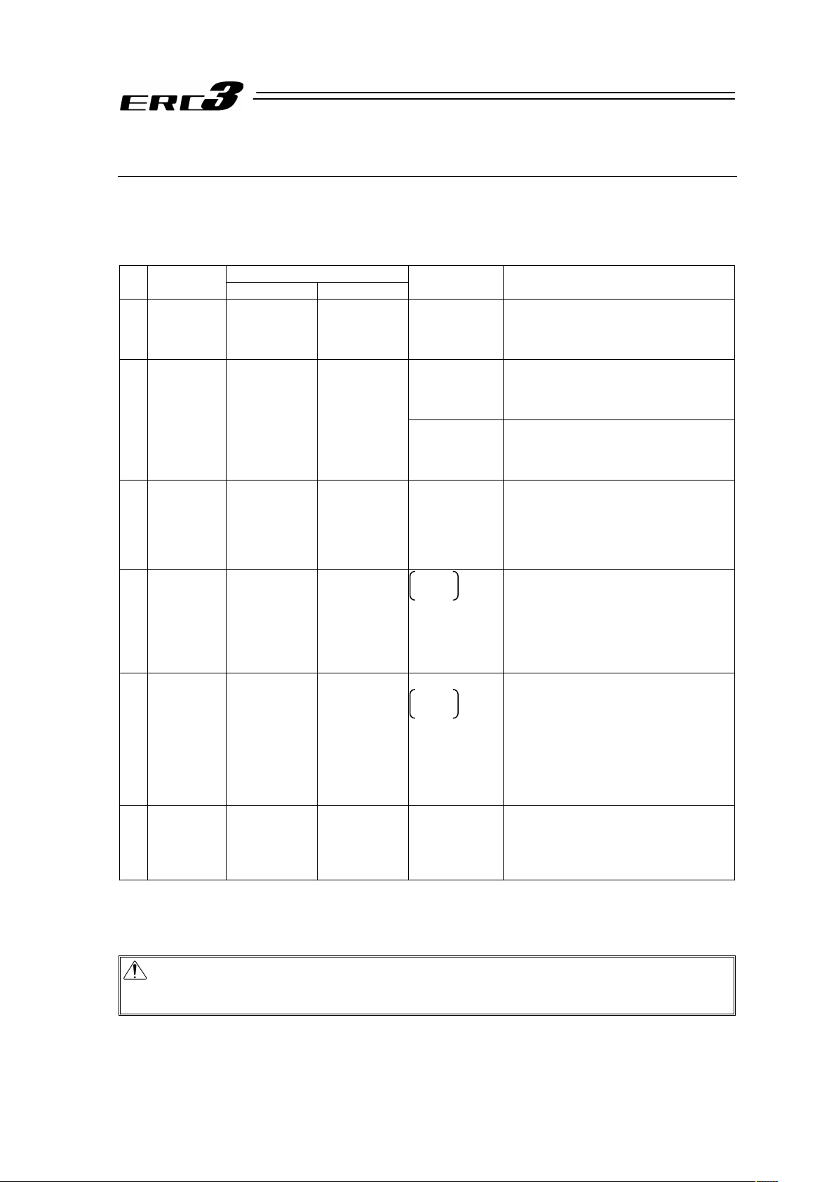
8
Guideline for Control Method
ERC3 has numerous operation patterns and options to meet many criteria for different applications.
Check Chapter 4 Operation for more details.
When Quick Teach is used with Con mode only Jog Operation is available.
Codes in brackets are model codes
Controller
No.
Type of
Operation
I/O Type Controller Type
Compulsory
Option
Overview
1 Positioner
Mode 1
(Standard
Type)
PIO Type
(NP/PN)
CON Mode
(CN)
– • Select from 3 types of PIO patterns for
the operation method
• Number of maximum positioning points:
16 points
– • An operation by pulse train input is
available.
• There are 2 types of operation methods
(Positioning/Pressing)
2 Pulse Train
Control
Mode
Pulse Train
Control Type
(PLN/PLP)
(Note 1)
CON Mode
(CN)
Pulse Converter
AK-04
• Applicable for open collector pulse train
output
• There are 2 types of operation methods
(Positioning/Pressing)
3 Positioner
Mode 2
(Expansion
Type)
SIO Type
(SE)
CON Mode
(CN)
PIO Converter • Select from 6 types of PIO patterns for
the operation method
• Number of maximum positioning points:
512 points
• Capable for Simple Absolute Type
application
4 MEC Mode 1 PIO Type
(NP/PN)
MEC Mode
(MC)
Quick
(Note 2)
Teach
• The same control as air cylinder is
available
• Simple operation is available with Quick
Teach (teaching pendant)
• There are 2 types of operation patterns
(2-Point Positioning/3-Point
Positioning)
5 MEC Mode 2 SIO Type
(SE)
MEC Mode
(MC)
PIO Converter
Quick
(Note 2)
Teach
• The same control as air cylinder is
available
• Simple operation is available with Quick
Teach (teaching pendant)
• There are 2 types of operation patterns
(2-Point Positioning/3-Point
Positioning)
• Capable for Simple Absolute Type
application
6 MEC Mode 3 SIO Type
(SE)
MEC Mode
(MC)
Quick Teach • Individual operation is available by
Quick Teach
• There are 2 types of operation patterns
(2-Point Positioning/3-Point
Positioning)
Note 1 The pulse train input is the differential input (Line Driver) type. For PLN, PIO is NPN type
and PLP is PNP type.
Note 2 It is also available to use any teaching tool other than Quick Teach.
Caution : The selection of the controller type is determined by the selection of the model code.
The type of built-in controller differs for each type. Since the hardware is different, it
is not possible to select the type with parameters after the product is delivered out.
Page 19

9
Precautions in Operation
1. It is set to “high output” when the machine is delivered from the factory.
There is a limit in the duty for the high output setting. Even though the transportable weight and
maximum speed decrease, an operation with the duty 100% becomes available if the high
output setting is set invalid in the parameters.
See 1.2.1 Settings for Valid/Invalid of High Output Setting for more details.
2. Set the operation patterns.
There are some operation (PIO) patterns prepared for each model classified by the built-in
controller.
Set the operation pattern and parameters suitable for the operation method of each model.
See Chapter 4 Operation for more details.
Caution : Please note it is very risky when the control sequence and PIO pattern setting do not
match to each other. It may not only cause the normal operation disabled, but also
may cause an unexpected operation.
3. Do not set speeds and accelerations/decelerations equal to or greater than the
respective ratings.
If the actuator is operated at a speed or acceleration/deceleration exceeding the allowable
value, abnormal noise or vibration, failure, or shorter life may result.
4. The allowable load moment for the slider type should be within the allowable
range.
If the actuator is operated under a load equal to or greater than the allowable load moment,
abnormal noise or vibration, failure, or shorter life may result. In an extreme case, flaking may
occur.
5. The overhung for the slider type should be within the allowable range.
Attaching a load beyond the allowable overhang length may generate vibration or abnormal
noise.
6. Do not attempt to apply a rotary torque the rod type.
Doing so may damage the internal component such as the rod stopper, and may result in an
operation failure.
7. Back and forth operation in short distance may wear out the oil film of the
grease.
If the actuator is moved back and forth continuously over a short distance of 30 mm or less,
grease film may run out. As a guide, move the actuator back and forth repeatedly for around 5
cycles over a distance of 50 mm or more after every 5,000 to 10,000 cycles. Keep using the
actuator with the grease worn out may cause malfunction. If it is extreme, flaking may occur on
the guide.
Page 20

10
8. Do not attempt to hit the slider or rod against an obstacle with high speed.
It may destroy the coupling.
9. Make sure to attach the actuator properly by following this instruction manual.
Using the product with the actuator not being certainly retained or affixed may cause abnormal
noise, vibration, malfunction or shorten the product life.
10. Make sure to follow the usage condition, environment and specification range
of the product.
Operation out of the guarantee could cause a drop in performance or malfunction of the
product.
11. Use the dedicated teaching tool.
Check 1.1.2 Teaching Tool for the PC software and teaching pendant available for this
controller.
12. Do not connect Quick Teach while a tool (teaching) is being connected to the
8-pin mini DIN connector on the ERC3 main unit.
Communication between ERC3 and the tool (teaching or PC) becomes unable.
13. Do not connect Quick Teach while a tool is being connected to TP connector
(8-pin mini DIN) on ERC3 side.
Since the communication with Quick Teach cannot be established, ERC3 cannot receive the
high-output invalid command and runs with the high-output setting condition, resulting in a
generation of the voltage drop error due to the capacity drop of the power supply unit inside
Quick Teach.
14. Backup the data to secure for breakdown.
A non-volatile memory is used as the backup memory for this controller. All the registered
position data and parameters are written into this memory and backed-up at the same time.
Therefore, you will not usually lose the data even if the power is shut down. However, make
sure to save the latest data so a quick recovery action can be taken in case when the controller
is broken and needs to be replaced with another one.
How to Save Data
(1) Save the data to CD-R or hard disk with using the PC software
(2) Hard-copy the information of position tables and parameters on paper
15. Clock Setting in Calendar Function
When power is supplied to the PIO converter for the first time, “Error Code 069 Real Time Clock
Vibration Stop Detected” May get generated. In the case this happens, set the current time with
a teaching tool.
If the battery is fully charged, the clock data is retained for approximately 10 days after the
power is turned OFF. Even though the time setting is conducted before the product is shipped
out, the battery is not fully charged. Therefore, there may be a case that the clock data is lost
even with fewer days than described above passed since the product is shipped out.
16. Pulse Train Control Type cannot be operated with the serial communication.
It is able, however, to monitor the current position or the conditions of the status.
Page 21

11
17. When using Pulse Train Control type, pay close attention to the pulse
frequency; so the frequency will no exceed the actuator specification.
In the pulse train control, the acceleration/deceleration speed is also controlled by the change
of the command pulse frequency from the host controller. Be careful not to exceed the
maximum acceleration/deceleration speed of the actuator. The use of the actuator with
excessive acceleration/deceleration rate may cause a malfunction.
18. For CON Mode Type, an operation cannot be made unless the servo-on signal
and pause signal are input.
(1) Servo ON Signal SON
Servo-on signal SON is selectable from either “Enable” or “Disable” by the parameter.
This setting can be performed in Parameter No.21 “Servo ON input disable selection”.
[Refer to Chapter 7 Parameters.]
If it is set to “Enable”, the actuator would not operate unless turning this signal ON.
If parameter No.21 is set to “1”, SON is made disable. If it is set to “Disable”, the servo
becomes ON and the actuator operation becomes enabled as soon as the power supply to
the controller is turned ON and the emergency stop signal is cancelled.
The factory setting is “0” (Enable). Have the setting that suits the desired control logic.
(2) Pause Signal *STP
The input signal of the pause signal *STP is always ON considering the safety. Therefore,
in general, the actuator would not operate if this signal is not ON.
It is available to make this signal to “Disable”, if this signal is undesirable.
It is settable by parameter No.15 “Pause input disable”.
[Refer to Chapter 7 Parameters.]
If parameter No.15 is set to “1” (Disable), the actuator can operate even if this signal is not
ON.
This parameter is set to “0” (Enable) at delivery.
Page 22
12
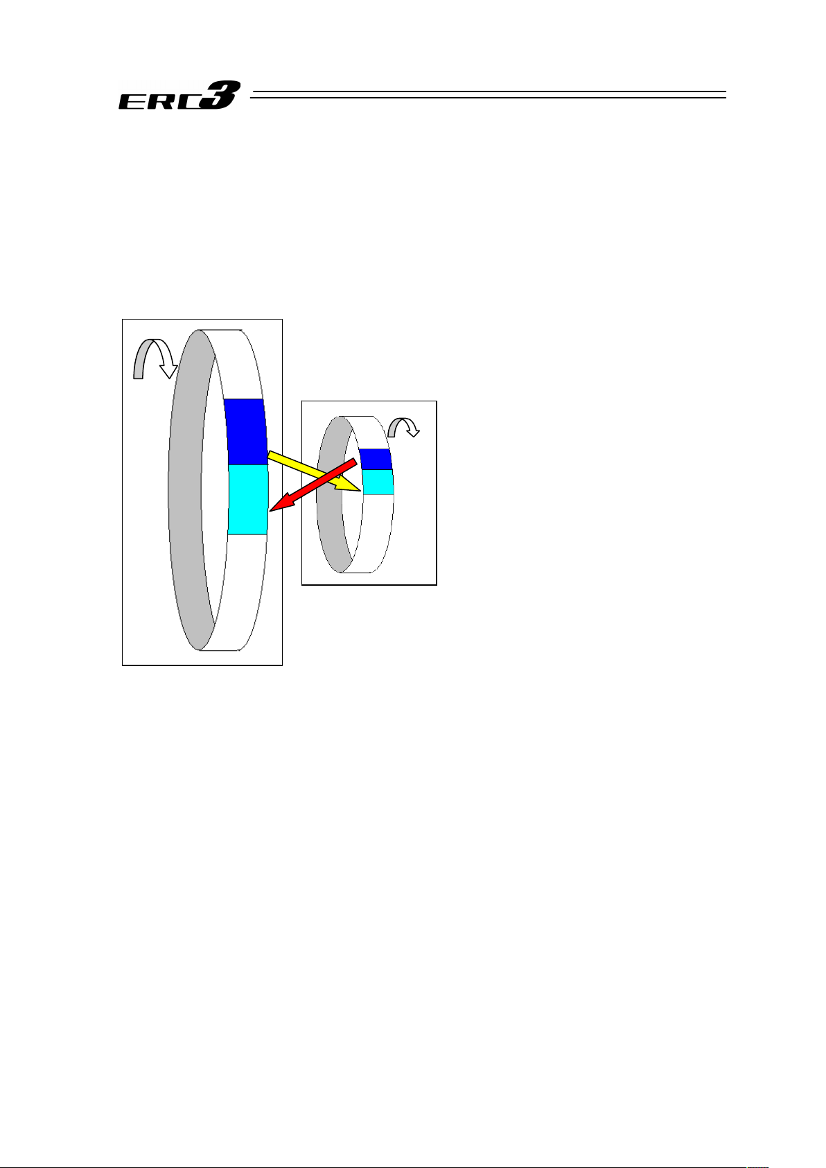
19. Transference of PIO Signal between Controllers
Please note the following when conducting transference of PIO signal between controllers.
To certainly transfer the signal between controllers with different scan time, it is necessary to
have longer scan time than the one longer than the other controller. To ensure to end the
process safely, it is recommended to have the timer setting more than twice as long as the
longer scan time at least.
䎃
Ɣ Operation Image
䎃
䎃
䎃
䎃
䎃
䎃
䎃
䎃
䎃
䎃
䎃
䎃
䎃
䎃
䎃
䎃
䎃
䎃
䎃
䎃
䎃
䎃
Also, if one tries to read the signal that is being re-written by the other, the signal may be read wrongly.
Make sure to read the signal after the rewriting is complete. (It is recommended to have more than 2 scan
periods to wait.) Make sure not to have the output side to change the output until the other side completes
the reading. Also, a setting is made on the input area not to receive the signal less than a certain time to
prevent a wrong reading of noise. This duration also needs to be considered.
20. PLC Timer Setting
Do not have the PLC timer setting to be done with the minimum setting.
Setting to “1” for 100msec timer turns ON at the timing from 0 to 100msec while 10msec timer
from 0 to 10msec for some PLC.
Therefore, the same process as when the timer is not set is held and may cause a failure such
as the actuator cannot get positioned to the indicated position number in Positioner Mode.
Set “2” as the minimum value for the setting of 10msec timer and when setting to 100msec, use
10msec timer and set to “10”.
This controller
(scan time 1msec)
PLC
(e.g. scan time is 20msec)
Output
Process
Input
Process
As shown in the diagram, the input and output
timings of two devices that have different scan
time do not match, of course, when transferring
a signal.
There is no guarantee that PLC would read the
signal as soon as this controller signal turns on.
In such a case, make the setting to read the
signal after a certain time that is longer than the
longer scan time to ensure the reading process
to succeed on the PLC side.
It is the same in the case this controller side
reads the signal.
In such a case, it is recommended to ensure 2
to 4 times of the scan time for the timer setting
margin.
It is risky to have the setting below the scan
time since the timer is also processed in the
scan process.
In the diagram, PLC can only read the input
once in 20msec even though this controller
output once in 1msec.
Because PLC only conducts output process
once in 20msec, this controller identifies the
same output status for that while.
Page 23

13
International Standards Compliances
This product complies with the following overseas standard.
RoHS Directive CE Marking
{
To be scheduled
Page 24
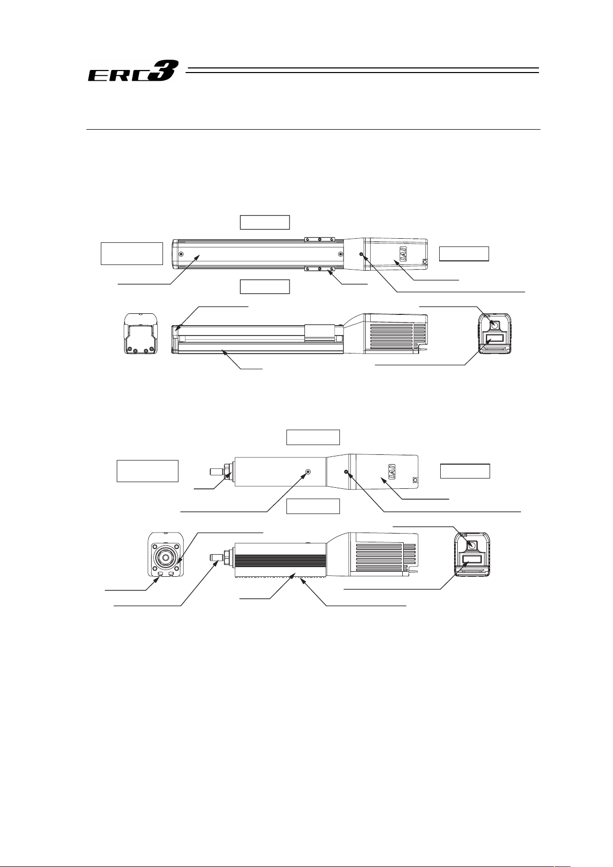
14
Names of the Parts
1. Main Body
In this instruction manual, the right and left sides of the actuator is expressed in the way it is placed
horizontally and is looked from the motor side as shown in the figure below.
(1) Slider Type
Right Side
Left Side
Screw Cover Slider
Motor Unit
Screw for motor unit attachment
Front Cover
Base
External I/F Connector
Teaching Port
Opposite Side
of the Motor
Motor Side
(2) Rod Type
Rod
Motor Unit
Screw for motor unit attachment
Rod End Fitting Range of T-groove
External I/F Connector
Teaching Port
Frame
Grease Supply Gate
(Thin-Head Screw)
Right Side
Left Side
Opposite Side
of the Motor
Motor Side
T-groove
Flange Surface
Page 25
15
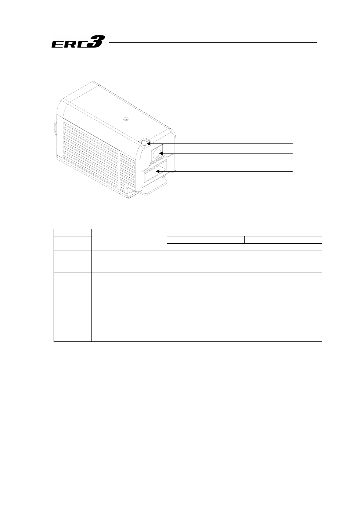
2. Motor Unit
1) Status Indicator LED
Following show the controller operation status:
{ : Illuminating × : OFF ڏ : Flashing
LED Status of PIO Output Signal
CON Mode Type MEC Mode Type
SV
(GN)
ALM
(RD)
Operation status
*ALM Output
(Note 1)
Control Power Supply ON ON
Control Power Supply OFF OFF
× ×
Servo OFF OFF
Motor driving power supply
OFF
OFF
Emergency Stop OFF
×
{
Alarm
(Operation cancellation level
or more)
OFF
{
× Servo ON ON
ڏ × During automatic servo-off ON
{ (OR)
In initializing process at
power being ON
OFF
Note 1 The output signals with * mark are the active low signals that turn ON in normal condition and turn
OFF while in abnormal condition.
2) Teaching Port
It is the connector dedicated for the connection of a teaching tool such as PC software.
3) External I/F Connector
It is I/F connector for controls with PIO and SIO.
1) Status Indicator LED (SV/ALM)
2) Teaching Port
3) External I/F Connector
Page 26

16
3. Option
(1) PIO Converter (Model: RCB-CV/CVG-**)
The functions of CON mode type in ERC3 can be extended. See 4.2.3 Operation in Positioner
Mode 2 for details.
Also, if ERC3 is Simple Absolute Type, the absolute battery is to be attached to this PIO
Converter, thus it is mandatory.
6) Status Indicator LED
5) Absolute Battery LED
(For Simple Absolute Type)
4) Brake Release Switch
3) SIO Connector
1) PIO Connector
11) FG Terminal Block
7) Absolute Reset LED
(For Simple Absolute Type)
8) Mode Changeover Switch
for Status LEDs
(with monitor LED)
9) Status Display Mode LED
(with monitor LED)
10) Status LED
(with monitor LED)
䎽䎃
2) Absolute Battery
(For Simple Absolute Type)
12) Power Supply
Connector
14) Absolute Battery Connector
(For Simple Absolute Type)
Z View
2) Absolute Battery
(For Simple Absolute Type)
13) ERC3
Connector
Page 27

17
1) PIO Connector (I/O) [Refer to 3.2.2 [2]]
The PIO connector is used for control I/O signals.
2) Absolute Battery [Refer to Chapter 6]
This is the battery to retain the encoder information for Simple Absolute Type. Affix it with
fabric hook-and-loop fastener on the side of PIO Converter.
If ERC3 is Simple Absolute Type, it is necessary that PIO Converter is a type that is
applicable for Simple Absolute Type.
3) SIO Connector (SIO) [Refer to 3.7.6]
This is the connector for the communication cable connection with a teaching tool such as
the PC software.
4) Brake Release Switch (RLS/NOM)
For the actuator equipped with a brake, the switch is used to release the brake forcibly.
RLS ···········Brake release
NOM··········Normal Operation (brake is activated)
Warning : Always set the switch to “NOM” in normal operation.
(Keep the chance to set the switch to RLS side as less as possible, and make
sure to set it on NOM side in ordinary use.)
The brake would not work even with the servo OFF condition if the switch is
on the RLS side. In the vertical oriented mount, the work may drop and cause
an injury or the work to be damaged.
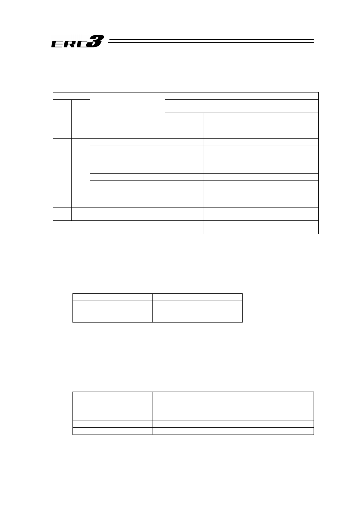
5) Absolute Battery LED (BAT)
It shows the absolute reset status, complete or incomplete.
It is equipped if applicable for Simple Absolute Type.
LED Operation Status
OFF Control Power Supply OFF
Green Light is turned ON. Battery Fully Charged
Orange Light is turned ON. Battery Charging Operation
Red Light is turned ON. Battery Disconnected
Page 28
18
6) Status Indicator LED (SYS)
Following show the controller operation status:
{ : Illuminating × : OFF ڏ : Flashing
LED Status of PIO Output Signal
CON Mode Type
MEC Mode
Type
SV
(GN)
ALM
(RD)
Operation status
SV Output
(Servo ON)
*ALM Output
(Note 1)
(Alarm)
*EMGS Output
(Note 1)(Note2)
(Emergency
Stop Status)
*ALM Output
(Note 1)
Control Power Supply ON OFF ON ON ON
Control Power Supply OFF OFF OFF OFF OFF
× ×
Servo OFF OFF OFF – OFF
Motor driving power supply
OFF
OFF OFF – OFF
Emergency Stop OFF OFF OFF OFF
×
{
Alarm
(Operation cancellation level
or more)
OFF OFF – OFF
{
× Servo ON ON ON ON ON
ڏ
×
During automatic servo-off
(Note 3)
OFF ON – ON
{ (OR)
In initializing process at power
being ON
OFF OFF – OFF
Note 1 The output signals with * mark are the active low signals that turn ON in normal condition and turn
OFF while in abnormal condition.
Note 2 *EMGS output is not prepared for Pulse Train Control Type.
Note 3 Servo-motor Auto OFF [Refer to Chapter 5 Power-saving Function]
7) Absolute Reset LED (ABS)
It shows the absolute reset status, complete or incomplete.
It is to be mounted to Simple Absolute Type.
LED Operation Status
OFF Control Power Supply OFF
Green Light is turned ON. Absolute Reset Complete
Red Light is turned ON. Absolute Reset Incomplete
8) Mode Changeover Switch for Status LEDs (SCT)
The display modes (0 to 3) of LED 0 to 15 switch over every time the switch is pressed and
the contents of display can be changed. The selection of the mode can be checked with the
color of Status Display Mode LED.
9) Status Display Mode LED (SYS)
The mode selected with Status LED Mode Changeover Switch is expressed with the display
colors.
LED Mode Contents of LED 0 to 15 Displays
OFF Mode 0
Command Current Ratio Level/
Control Power Supply OFF
Green Light is turned ON. Mode 1 Alarm Code
Yellow Light is turned ON. Mode 2 Monitoring of PIO input signal
Red Light is turned ON. Mode 3 Monitoring of PIO output signal
Page 29
19
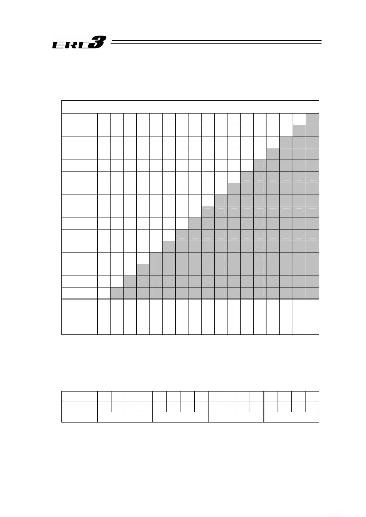
10) Status LED (0 to 15)
• Display while Mode 0 (Command Current Ratio Level) being selected
The command current ratio level of the motor rated current as 100% is displayed in a bar
graph with green lights.
{: LED Illuminating, × : LED OFF
Status of LEDs
15 × × × × × × × × × × × × × × × ×
{
14 × × × × × × × × × × × × × × ×
{ {
13 × × × × × × × × × × × × × ×
{ { {
12 × × × × × × × × × × × × ×
{ { { {
11 × × × × × × × × × × × ×
{ { { { {
10 × × × × × × × × × × ×
{ { { { { {
9 × × × × × × × × × ×
{ { { { { { {
8 × × × × × × × × ×
{ { { { { { { {
7 × × × × × × × ×
{ { { { { { { { {
6 × × × × × × ×
{ { { { { { { { { {
5 × × × × × ×
{ { { { { { { { { { {
4 × × × × ×
{ { { { { { { { { { { {
3 × × × ×
{ { { { { { { { { { { { {
2 × × ×
{ { { { { { { { { { { { { {
1 × ×
{ { { { { { { { { { { { { { {
0 ×
{ { { { { { { { { { { { { { { {
Command
Current
Ratio [%]
0
to 6.24
to 12.24
to 18.74
to 24.99
to 31.24
to 37.49
to 43.74
to 49.99
to 56.24
to 62.49
to 68.74
to 74.99
to 81.24
to 87.49
to 93.74
to 100.00
• Display while Mode 1 (Alarm Code) being selected [refer to Chapter 7 for Alarm Codes]
The alarm code issued in ERC3 is displayed in the hexadecimal system with the LED 0 to
15 used as 1 word of bit 0 to 15.
(Example) If Alarm Code “083” (absolute position movement command at home-return
incomplete) is generated, the display is as shown below:
{: LED Illuminating, × : LED OFF
LED 15 14 13 12 11 10 9 8 7 6 5 4 3 2 1 0
Alarm Display × × × × × × × ×
{
× × × × ×
{ {
Alarm Code 0 0 8 3
Page 30

20
• Display while Mode 2 (PIO Input Signal Monitor) being selected
It displays the status of PIO control input (PLC ĺ PIO Converter) whether it is ON or OFF.
[Refer to 2.1 [2]]
LED turned ON in green : input signal ON
LED being OFF : input signal OFF
• Display while Mode 2 (PIO Output Signal Monitor) being selected
It displays the status of PIO control input (PIO Converter ĺ PLC) whether it is ON or OFF.
[Refer to 2.1 [2]]
LED turned ON in green : output signal ON
LED being OFF : output signal OFF
11) FG Terminal Block [Refer to 2.3.4 [1] (2)]
This is the grounding terminal for protection from electric shock and noise. Make sure to
conduct the Class D grounding (formerly Class 3 grounding: grounding resistance at 100 or
less).
12) Power Supply Connector [Refer to 3.3.3 [1], 3.5.3 [1]]
This is the connector for the connections of power supply, emergency stop input, driving
cutoff and the emergency stop switch signal output for the teaching pendant.
13) ERC3 Connector [Refer to 3.3.3 [2], 3.5.3 [2]]
This is the connector for the relay cable to connect ERC3 and PIO Converter.
14) Absolute Battery Connector [Refer to Chapter 6]
It is the connector to plug in the enclosed battery if applicable for Simple Absolute Type.
Page 31

21
(2) Quick Teach (Model: RCM-PST-**)
You can operate ERC3 easily. Not only JOG operation and home-return operation, but also the
settings and changes of stop positions (2 or 3 points), acceleration/deceleration, speed and try
run (forward / backward / continuous operations) are available.
Check Chapter 4 Operation for the functions of each LED and operation switch.
1) Emergency Stop Connector
2) External 24V Connector
3) ERC3 Connector
4) Brake Release Switch
5) 24V DC Power Supply Unit
With 24V DC Power Supply Unit
Model: RCM-PST-1
RCM-PST-2
RCM-PST-EU
24V Power Supply Type
Model: RCM-PST-0
Page 32

22
1) Emergency Stop Connector [Refer to Chapter 2]
This is the input connector for the external emergency stop signals. There is a plug equipped
with a jumper cable attached on at the delivery. Remove the jumper when a wiring for the
external emergency stop is required. Connect a signal that turns ON in normal condition and
OFF when in abnormal for the external emergency stop signal.
2) External 24V Connector
Use this connector to supply power when it is not equipped with
24V DC power supply unit or is to be used without the power
supply unit being attached.
Power Supply 24V DC ±10% 2.5A or more
When the excitation detection is operating after the
power is turned ON (normally for 100ms) MAX. 2.5A
3) ERC3 Connector
When operating ERC3 directly with Quick Teach, plug the SIO type power supply and I/O
cable.
When Quick Teach is used as the teaching pendant, plug the SIO communication cable.
Power for SIO Type • I/O Cable : Model CB-ERC3S-PWBIOƑƑƑ
(ƑƑƑ shows the cable length, Example 020 = 2m,
MAX. 10m)
SIO Communication Cable : Model CB-PST-SIO050 (Standard 5m)
4) Brake Release Switch
This is a switch to compulsorily release the brake of the actuator equipped with a brake.
Release ····· Brake release
Normal·······Normal Operation (brake is activated)
Warning : Always set the switch to “Normal” in normal operation.
(Keep the chance to set the switch to release side as less as possible, and
make sure to set it on normal side in ordinary use.)
The brake would not work even with the servo OFF condition if the switch is
on the release side. In the vertical oriented mount, the work may drop and
cause an injury or the work to be damaged.
5) 24V DC Power Supply Unit
This is a 24V DC power supply unit to provide power to Quick Teach from AC power source.
This can be used with being detached. It is necessary to provide power from external 24V
connector when it is detached.
Quick Teach Model Power Voltage
Rated
Current
Peak
Current
Remarks
RCM-PST-1 (100V Type)
Single-phase 100 to 115V AC
±10%
2.5A 3.2A
Cable 2m
Equipped with 3-pin
power socket plug
RCM-PST-2 (200V Type)
Single-phase 100 to 230V AC
±10%
2.1A
RCM-PST-EU
(200V type for Europe)
Single-phase 100 to 230V AC
±10%
2.1A
Cable 2m
Equipped with
I4.3-hole
solderless ring
tongue terminals
+
–
Page 33

23
Actuator Coordinate
The coordinate system of ERC3 is as shown below.
0 defines the home position, and items in ( ) are for the home-reversed type (option).
For MEC Mode, the home position is the origin point and positive side is the end point.
(1) Rod Type
(2) Slider Type
+
(0)
0
(+)
+
(0)
0
(+)
Page 34

24
Starting Procedures
1. Positioner Mode 1
When using this product for the first time, make sure to avoid mistakes and incorrect wiring by
referring to the procedure below. “PC” stated in this section means “RC PC software”.
Caution
Please perform this process with the actuator away from the mechanical end or
interfering subjects as much as possible. Put the actuator away if it interferes with
surroundings. It may generate an alarm if the actuator hit the mechanical end or
interfering subjects when the servo is turned ON.
The slider may get slightly dropped by self-weight if servo ON and OFF is repeatedly
performed at the same position. Be careful not to pinch the hand or damage the work.
Ļ Yes
ĺ
No ĺ
Ļ
ĺ
No ĺ
Contact us or our distributor.
Ļ Yes
No ĺ
ĺ
Check Item
Is the red light [ALM] on the
LED status display OFF?
Connect the teaching tool
such as PC to confirm the
content of alarm and have
an appropriate treatment.
Servo ON
Turn the servo ON with the operation on the teaching tool such as PC.
Check Item
Does the status
LED [SV] on the
panel?
Safety Circuit Check
Does the emergency stop circuit (drive cutoff circuit) work properly and turn
the servo OFF?
Check the emergency stop circuit.
Target Position Setting
Set the target position in “Position” Box in each position table.
Perform a home-return operation first when Direct Teaching is to be performed. When moving the actuator manually with hand,
supply +24V to BK in PIO to release the brake before doing so. Put the switch back after the setting is complete.
ĺ
No ĺ
Ļ Yes
Safety Speed Setting
Set the Parameter No.35 if necessary.
The safet
y sp
eed is set to 100mm/s at the delivery.
Ļ
Test Run Adjustment 1
Check the operation without mounting a
work and set the safety speed invalid on
the teaching tool such as PC, and then
check the operation with a work mounted.
Check if there is any problem with the
installation of the actuator and the condition of
the actuator use exceeds the ranges of the rated
values.
Adjust the servo if necessary.
Power Supply and Alarm Check
Connect a teaching tool such as PC, turn the power
ON for unit.
Select [Teaching Mode 1 Safety Speed Activated /
PIO Operation Invalid] in the teaching tool such as
PC.
If an alarm is
generated, connect
the PC or teaching
pendant and check
the content of the
alarm to have the
right treatment.
Ļ Yes
ĸ Yes
Test Run Adjustment 2
1) Set Teach Mode to Monitor Mode 2 and disconnect the teaching tool.
2) Output the operation command from PLC to the controller and check the system operation.
Check Item
Any vibration or
abnormal noise?
No ĺ
Ļ Yes
Check of Packed Items
Are there all the delivered items?
Caution To ensure safety, it is recommended
that safety speed be enabled during
initial movements.
Installation and Wiring [Refer to Chapter 2 and
Chapter 3]
Perform the installation of and wiring for the actuator.
Point Check Item [Refer to Section 2.3.4]
• Is frame ground (FG) connected?
• Has the noise countermeasure been taken?
Warning Be careful not to pinch fingers or damage the work with the dropped actuator when releasing the brake in
vertical orientation.
PIO Pattern Settings
Set the PIO
p
attern used to Parameter No.25.
Page 35

25
2. Pulse Train Control Mode
This product allows positioning control by the pulse train.
It is necessary to have the positioning control function able to output the pulse train on the host
controller (PLC).
When using this product for the first time, make sure to avoid mistakes and incorrect wiring by
referring to the procedure below. “PC” stated in this section means “RC PC software”.
Set the Electronic Gear [Refer to Section
4.3 [8] (1)]
Set the electronic gear ratio based on the
amount of actuator operation per pulse in
Parameters No.65 and 66.
ψ
Check Item
Is the minimum unit of operation set to the value bigger than the
minimum resolution of the encoder?
Is the fraction of the electronic gear ratio reduced to its lowest terms?
φYes
Pulse Train Input Output Mode Setting [Refer to Section 4.3 [8] (2)]
Set the command pulse train input status for the parameter No.63 and No.64.
Set Teach Mode to Monitor Mode 2 and disconnect the teaching tool after the setting is complete.
Servo ON
Input servo ON signal from PLC.
ψ
Check Item
Does the status LED
[SV] on the panel?
No ψ
Confirm the content of alarm on the teaching
tool such as PC to have an appropriate
treatment.
φYes
Safety Circuit Check
Check that the emergency stop circuit (or motor
drive-power cutoff circuit) operates normally to turn
OFF the servo.
No ψ
Check the emergency stop circuit.
ωYes
ψ
No ψ
Contact us or our distributor.
ωYes
No ψ
ψ
Check Item
Is the red light [ALM] on the
LED status display OFF?
Connect the teaching tool
such as PC to confirm the
content of alarm and have
an appropriate treatment.
Test Run Adjustment 2
[Operation Mode AUTO]
Output the pulse train from PLC to
the controller and check the
system operation.
ψ
No ψ
No ψ
Check the electronic gear ratio setting.
Confirm the command pulse train input mode
setting.
Confirm that there is no problem in the
actuator installation, the actuator operation
condition demands a voltage more than rated
voltage, and appropriate pulse trains are input.
Power Supply and Alarm Check
Connect a teaching tool such as PC, turn the power
ON for unit.
Select [Teaching Mode 1 Safety Speed Activated /
PIO Operation Invalid] in the teaching tool such as
PC.
ωYes
φYes
Check of Packed Items
Are there all the delivered items?
Installation and Wiring [Refer to Chapter 2 and Chapter
3]
Perform the installation of and wiring for the actuator and
controller.
Point Check Item [Refer to Section 2.3.4]
• Is frame ground (FG) connected?
• Has the noise countermeasure been taken?
ψ
Test Run Adjustment 1
[Operation Mode MANU]
Check with a teaching tool such as the
PC with no work being loaded, and check
the operation range with JOG operation
with the work being loaded.
Check if there is any problem in the way of
actuator mount.
Check Item
Is there any risk of
interfering with
peripheral
equipment?
No ψ
ωYes
Can the positioning
operation be performed
normally?
ωYes
ωYes
Is it in condition without
any vibration and
abnormal noise?
Test Run Adjustment 3
Check the system operation conducted by PLC.
PIO Pattern Settings
Set 0 or 1 to Parameter No.25 (Pulse Train Control Mode).
Page 36

26
3. Positioner Mode 2
When using this product for the first time, make sure to avoid mistakes and incorrect wiring by
referring to the procedure below. “PC” stated in this section means “RC PC software”.
Caution
Please perform this process with the actuator away from the mechanical end or
interfering subjects as much as possible. Put the actuator away if it interferes with
surroundings. It may generate an alarm if the actuator hit the mechanical end or
interfering subjects when the servo is turned ON.
The slider may get slightly dropped by self-weight if servo ON and OFF is repeatedly
performed at the same position. Be careful not to pinch the hand or damage the work.
Ļ Yes
ĺ
No ĺ
Ļ
ĺ
No ĺ
Contact us or our distributor.
Ļ Yes
No ĺ
ĺ
Check Item
Is the red light [ALM] on the
LED status display OFF?
Connect the teaching tool
such as PC to confirm the
content of alarm and have
an appropriate treatment.
Servo ON
Turn the servo ON with the operation on the teaching tool such as PC.
Check Item
Does the status
LED [SV] on the
panel?
Safety Circuit Check
Does the emergency stop circuit (drive cutoff circuit) work properly and turn
the servo OFF?
Check the emergency stop circuit.
Target Position Setting
Set the target position in “Position” Box in each position table.
Perform a home-return operation first when Direct Teaching is to be performed. When moving the actuator manually, set the
Brake Release Switch to [BK RLS] side for the brake equipped type. Put the switch back after the setting is complete.
ĺ
No ĺ
Ļ Yes
Safety Speed Setting
Set the Parameter No.35 if necessary.
The safety speed is set to 100mm/s at the delivery.
Ļ
Test Run Adjustment 1
Check the operation without mounting a
work and set the safety speed invalid on
the teaching tool such as PC, and then
check the operation with a work mounted.
Check if there is any problem with the
installation of the actuator and the condition of
the actuator use exceeds the ranges of the rated
values.
Adjust the servo if necessary.
Power Supply and Alarm Check
Connect a teaching tool such as PC, turn the power
ON for unit.
Select [Teaching Mode 1 Safety Speed Activated /
PIO Operation Invalid] in the teaching tool such as
PC.
If an alarm is
generated, connect
the PC or teaching
pendant and check
the content of the
alarm to have the
right treatment.
Ļ Yes
ĸ Yes
Test Run Adjustment 2
1) Set Teach Mode to Monitor Mode 2 and disconnect the teaching tool.
2) Output the operation command from PLC to the controller and check the system operation.
Check Item
Any vibration or
abnormal noise?
No ĺ
Ļ Yes
Check of Packed Items
Are there all the delivered items?
Caution To ensure safety, it is recommended
that safety speed be enabled during
initial movements.
Installation and Wiring [Refer to Chapter 2 and
Chapter 3]
Perform the installation of and wiring for the actuator.
Point Check Item [Refer to Section 2.3.4]
• Is frame ground (FG) connected?
• Has the noise countermeasure been taken?
Warning In the case the actuator is installed in vertical orientation and put the brake release switch to [BK RLS] side, be
careful not to drop it with self-weight and pinch your hand or damage the work.
PIO Pattern Settings
Set the PIO
p
attern used to Parameter No.25.
Page 37

27
4. MEC Mode 1
When using this product for the first time, make sure to avoid mistakes and incorrect wiring by
referring to the procedure below. “PC” stated in this section means “MEC PC software”.
ĺ
Ļ
ĺ
No ĺ
Contact us or our distributor.
Ļ Yes
No ĺ
ĺ
Check Item
Is the green light [SV] on the
LED status display ON?
Connect the teaching tool
such as PC to confirm the
content of alarm and have
an appropriate treatment.
Safety Circuit Check
Does the emergency stop circuit (drive cutoff circuit) work properly and turn
the servo OFF?
Check the emergency stop circuit.
No ĺ
Ļ Yes
Test Run Adjustment 1
Check the operation without mounting a
work and set the safety speed invalid on
the teaching tool such as PC, and then
check the operation with a work mounted.
Check if there is any problem with the
installation of the actuator and the condition of
the actuator use exceeds the ranges of the rated
values.
Adjust the servo if necessary.
Ļ Yes
ĸ Yes
Test Run Adjustment 2
Output the operation command from PLC to the controller and check the system operation.
Check Item
Any vibration or
abnormal noise?
No ĺ
Ļ Yes
Check of Packed Items
Are there all the delivered items?
Caution To ensure safety, it is recommended that
safety speed be enabled during initial
movements.
Installation and Wiring [Refer to Chapter 2 and
Chapter 3]
Perform the installation of and wiring for the actuator.
Point Check Item [Refer to Section 2.3.4]
• Is frame ground (FG) connected?
• Has the noise countermeasure been taken?
Settings of Initial Setting, Target Position, etc.
Establish the initial settings for such as stop positions (for 2-point stop and 3-point stop), whether to have the pressing operation,
etc.
Secondly, set the parameters such as target position, acceleration and deceleration in the operational condition table.
Perform a home-return operation first when Direct Teaching is to be performed.
Warning When installing the product vertically and using Direct Teach, and if servo is turned on/off repeatedly at the
same position, the actuator may drop slightly with its weight. Be careful not to pinch the hand or damage the
work.
Power Supply and Alarm Check
Connect a teaching tool such as PC, turn the power
ON for unit.
Page 38

28
5. MEC Mode 2
When using this product for the first time, make sure to avoid mistakes and incorrect wiring by
referring to the procedure below. “PC” stated in this section means “MEC PC software”.
ĺ
Ļ
ĺ
No ĺ
Contact us or our distributor.
Ļ Yes
No ĺ
ĺ
Check Item
Is the green [SV] turned ON
in the ERC3 and PIO
Converter Status Display
LEDs?
Connect the teaching tool
such as PC to confirm the
content of alarm and have
an appropriate treatment.
Safety Circuit Check
Does the emergency stop circuit (drive cutoff circuit) work properly and turn
the servo OFF?
Check the emergency stop circuit.
No ĺ
Ļ Yes
Test Run Adjustment 1
Check the operation without mounting a
work and set the safety speed invalid on
the teaching tool such as PC, and then
check the operation with a work mounted.
Check if there is any problem with the
installation of the actuator and the condition of
the actuator use exceeds the ranges of the rated
values.
Adjust the servo if necessary.
Ļ Yes
ĸ Yes
Test Run Adjustment 2
Output the operation command from PLC to the controller and check the system operation.
Check Item
Any vibration or
abnormal noise?
No ĺ
Ļ Yes
Check of Packed Items
Are there all the delivered items?
Caution To ensure safety, it is recommended that
safety speed be enabled during initial
movements.
Installation and Wiring [Refer to Chapter 2 and
Chapter 3]
Perform the installation of and wiring for the actuator.
Point Check Item [Refer to Section 2.3.4]
• Is frame ground (FG) connected?
• Has the noise countermeasure been taken?
Settings of Initial Setting, Target Position, etc.
Establish the initial settings for such as stop positions (for 2-point stop and 3-point stop), whether to have the pressing operation,
etc.
Secondly, set the parameters such as target position, acceleration and deceleration in the operational condition table.
Perform a home-return operation first when Direct Teaching is to be performed.
Warning When installing the product vertically and using Direct Teach, and if servo is turned on/off repeatedly at the
same position, the actuator may drop slightly with its weight. Be careful not to pinch the hand or damage the
work.
Power Supply and Alarm Check
Connect a teaching tool such as PC to PIO Converter
and turn the power ON.
Page 39

29
6. MEC Mode 3
When using this product for the first time, make sure to avoid mistakes and incorrect wiring by
referring to the procedure below. “PC” stated in this section means “MEC PC software”.
ĻYes
Yesĺ
NoĻ
No ĺ
ĻYes
No ĺ
ĻYes
ĻYes
No ĺ
ĺ
ĺ
Ļ
Check of Packed Items
Are there all the delivered items?
Installation and Wiring [Refer to Chapter 2 and Chapter 3]
Perform the installation of and wiring for the quick teach and
actuator according to the instructions in the Instruction Manual
for the actuator and this Instruction Manual.
Contact us or our distributor.
Point Check Item [Refer to Section 2.3.4]
• Is the safety grounding conducted?
• Has the noise countermeasure been
taken?
Power Supply and Alarm Check
Turn ON the power.
The motor power (servo) automatically
turns ON by supplying the power.
Check Item
Is the error display LED
flashing in red?
Confirm that the emergency stop
switch has been cancelled.
If it is cancelled and there is a
teaching tool such as PC connected,
check the detail of the alarm and have
an appropriate treatment.
Safety Circuit Check
Check if the emergency stop circuit is operated in normal
condition.
Check the emergency stop circuit.
Setting of stop position [1.7]
Set the target position on the operation panel.
Test Run Adjustment [1.8]
Have the settings of velocity and acceleration on the
operation panel.
Set the speed low first. After confirming there is no
problem, set the speed to the desired setting.
Is it in condition without
any vibration and
abnormal noise?
Check if there is a problem in the
actuator attachment, or the usage of the
actuator is beyond the specification.
Now it is ready for operation.
ĸ
Page 40

30
Page 41

31
Chapter 1 Specifications Check
1.1 Product Check
1.1.1 Parts
This product is comprised of the following parts if it is of standard configuration.
If you find any fault in the contained model or any missing parts, contact us or our distributor.
(1) ERC3 Main Body
No. Part Name Model Remarks
1 ERC3 Main Body
Refer to “How to read the model plate”,
“How to read the model”.
Accessories
Except for SE
Type
CB-ERC3P-PWBIOƑƑƑ
2
Power Supply
• I/O Cable
SE Type CB-ERC3S-PWBIOƑƑƑ
ƑƑƑ shows the
cable length
(Example)
ƑƑƑ : 020 2 [m]
3 First Step Guide
4 Instruction Manual (DVD)
5 Safety Guide
6 Pulse Converter (Option) AK-04
It is necessary when
pulse control is to be
conducted and host
controller is the
open collector type.
(2) PIO Converter (Option: SE: Serial Communicate Type)
No. Part Name Model Remarks
1 PIO Converter Main Body
Refer to “How to read the model plate”,
“How to read the model”.
Accessories
2 I/O Flat Cable CB-PAC-PIOƑƑƑ
ƑƑƑ shows the
cable length
(Example)
ƑƑƑ : 020 2 [m]
3 Power Connector
FMC1.5/7-ST-3.5
(Supplier : PHOENIX CONTACT)
Recommended
cable size
AWG16 to 18
(1.25 to 0.75mm
2
)
4
Absolute Battery
(For Simple Absolute Type)
AB-7
5 Safety Guide
(3) Quick Teach (Option: SE: Serial Communicate Type (Specially for MEC Mode Type))
No. Part Name Model Remarks
1 Main Body
Refer to “How to read the model plate”,
“How to read the model”.
Accessories
2
2-pin plug connector for
external 24V power input
733-102-CC
(Supplier : WAGO)
Recommended
cable size
AWG20
(0.5mm
2
)
3 2-pin plug connector for EMG
FMC1.5/2-ST-3.5
(Supplier : PHOENIX CONTACT)
Recommended
cable size
AWG16 to 24
(0.2 to 1.25mm
2
)
Short-circuited when
delivered
4 Safety Guide
Chapter 1 Specications Check 1.1 Product Check
Page 42

Chapter 1 Specications Check1.1 Product Check
32
1.1.2 Teaching Tool
The teaching tool is necessary to perform setup operations such as position and parameter
settings through teaching or other means. The teaching tools listed below are available for
ERC3. However, the available teaching tools differ for MEC Mode Type and CON Mode Type.
Prepare an appropriate one considering the controller type.
({: Available ×: Unavailable)
Controller Type
No. Part Name Model
CON Mode Type
(Model: CN)
MEC Mode Type
(Model: MC)
1 Quick Teach RCM-PST-0 ×
{
2
PC Software
(Includes RS232C Exchange Adapter
Peripheral Communication Cable)
RCM-101-MW
{
×
3
PC Software
(Includes USB Exchange Adapter USB
Cable Peripheral Communication
Cable)
RCM-101-USB
{
×
4 MEC PC Software – ×
{
5
Teaching Pendant
(Touch Panel Teaching)
CON-PTA
{ {
6
Teaching Pendant
(Touch Panel Teaching with deadman
switch)
CON-PDA
{ {
7
Teaching Pendant
(Touch Panel Teaching with deadman
switch TP Adapter (RCB-LB-TG))
CON-PGA
{ {
8 Teaching Pendant SEP-PT ×
{
1.1.3 Instruction manuals related to this product, which are contained in the DVD.
No. Name Manual No.
1 ERC3 Controller Instruction Manual ME0297
2
PC Software
RCM-101-MW/ RCM-101-USB Instruction Manual
ME0155
3 MEC PC Software Instruction Manual ME0248
4 Touch Panel Teaching CON-PTA/PDA/PGA Instruction Manual ME0295
5 Touch Panel Teaching SEP-PT Instruction Manual ME0217
6 Instruction Manual for the serial communication [for Modbus] ME0162
Page 43

33
1.1.4 How to read the model plate
(1) ERC3 Main Body
(2) PIO Converter (Option)
(3) Quick Teach (Option)
Model
Serial numbe
r
ERC3-SA5-I-42P-20-50-SE-S-CN-B
MODEL
SERIAL No.
000049893
MADE IN JAPAN
RCB-CV-NPM-2-AB
MODEL
SERIAL No.
000049894
MADE IN JAPAN
Model
Serial numbe
r
Model
Serial numbe
r
㪤㪦㪛㪜㪣䋺㪩㪚㪤㪄㪧㪪㪫㪄㪇
㪪㪆㪥䇭䇭䋺
㪠㪥㪧㪬㪫㩷䋺㪛㪚㪉㪋㪭㪃㪉㪮㩿㪤㪘㪯㪀
㪤㪘㪛㪜㩷㪠㪥㩷㪡㪘㪧㪘㪥
Chapter 1 Specications Check 1.1 Product Check
Page 44

Chapter 1 Specications Check1.1 Product Check
34
1.1.5 How to read the model
(1) ERC3 Main Body
ERC3 – SA5 – I – 42P – 20 – 50 – SE – S – CN – B – **
Note 1 Identification for IAI use only : This may be marked for the purpose of IAI. It is not
an ID to describe the model code.
Note 2 The pulse train input is the differential input (Line Driver) type. For PLN, PIO is
NPN type and PLP is PNP type.
Series Name
<Type>
Slider Type
SA5C
SA7C
Rod Type
RA4C
RA6C
<Encoder Type>
I : Incremental
<Motor Type>
42P : 42Ƒ
56P : 56Ƒ
<Lead>
3 : 3mm
4 : 4mm
6 : 6mm
8 : 8mm
12 : 12mm
16 : 16mm
20 : 20mm
24 : 24mm
Identification for IAI use only
(Note 1)
<Option>
B : Brake
NM : Reversed Home Specification
ABU : Simple Absolute Type
FL : Flange
FT : Foot bracket
<Controller Type>
CN : CON Mode
MC : MEC Mode
<Cable Length>
N : None
S : 3m
M : 5m
XƑƑ : Specified Length
<I/O Type>
SE : Serial Communication Type
NP : PIO NPN Type
PLN : Pulse Train NPN Type
(Note 2)
PN : PIO PNP Type
PLP : Pulse Train PNP Type
(Note 2)
<Stroke>
[Refer to 1.2 Specifications,
[2] Maximum speed]
Page 45

35
(2) PIO Converter (Option)
RCB – CV – NPM – 2 – AB – **
(3) Quick Teach (Option)
RCM - PST - 0 – ENG – **
Note 1 Identification for IAI use only : This may be marked for the purpose of IAI. It is not
an ID to describe the model code.
Series Name
<Type>
CV : Built-in Power Cutoff Relay Type (Standard)
CVG : External Power Cutoff Relay Type
<I/O Type>
NP : NPN Type (with no monitor LED)
PN : PNP Type (with no monitor LED)
NPM : NPN Type (with monitor LED)
PNM : PNP Type (with monitor LED)
Identification for IAI use only
(Note 1)
<Option>
(Not Specified) :
Not applicable for Simple Absolute Type
(dedicated for Incremental Type)
AB : Applicable for Simple Absolute Type
(equipped with simple absolute battery)
ABUN : Applicable for Simple Absolute Type
(not equipped with simple absolute battery)
<I/O Cable Length>
0 : No cable
2 : with 2m cables
3 : with 3m cables
5 : with 5m cables
Series Name
<Unit Name>
PST : Product Unit
PS : Power Supply Unit
<Power Voltage>
0 : 24V DC (24V DC power supply type, no power supply unit)
1 : Single-phase 100V AC (100V AC power supply type)
2 : Single-phase 100 to 230V AC (200V AC power supply type)
EU : Single-phase 100 to 230V AC (200V AC power supply type for Europe)
Identification for IAI use only
(Note 1)
<Japan/Overseas specifications>
None : Destination Japan
(Panel sheet displayed in Japanese)
ENG : Destination Overseas
(Panel sheet displayed in English)
Chapter 1 Specications Check 1.1 Product Check
Page 46

Chapter 1 Specications Check1.2 Specications
1.2.1 Actuator
36
1.2 Specifications
1.2.1 Actuator
[1] High Output Setting
(1) Enabling/Disabling of High Output Setting
This actuator can select whether to enable / disable the high output setting by the
parameters.
At the delivery, the high output setting is activated for all the controllers.
Controller Type Parameter Setting Set Value
Enabled 1 (At the delivery)
CON Mode Type
No.152
High Output Setting
Disabled 0
Enabled 1 (At the delivery)
MEC Mode Type
No.28
High Output Setting
Disabled 0
1) The maximum speed, acceleration, and transportable weight differ when high output
setting is enabled and disabled.
[Refer to [3] Mechanical Specifications]
2) An operation with the duty 100% is available if the high output setting is inactivated. The
actuator cannot operate with 100% when it is activated.
Duty ratio is the rate of operation expressed in % that presents the time of the actuator
being operated in 1 cycle of operation.
D = ×100 [%]
Caution: Please note that the high output setting becomes invalid automatically if Quick
Teach is connected.
D : Duty
T
M
: Operation time (pressing operation included)
T
R
: Stop time
T
M
TM+T
R
Speed
Deceleration
A
cceleration
Constant Speed
Stop
Operation time T
M
Stop time T
R
Time of one cycle
Page 47

37
(2) Duty Ratio for High Output Setting
When high output setting is enabled, duty is restrained respective to the surrounding
temperature to control heat generation by the motor unit.
Perform an operation with the duty ratio below the allowable range shown in the graph
below.
Make sure to have 1 cycle within the time described below:
Model Name Time of one cycle (TM+TR)
SA5/RA4 15min. or less
SA7/RA6 10min. or less
Caution: Do not attempt to perform an operation with the duty ratio above the allowable
range. An operation with the duty ratio beyond the allowable range could
shorten the life of the capacitor used in the build-in controller by the generation
of heat on the motor.
Surrounding temperature [qC]
Duty [%]
㪋㪇
㪌㪇
㪍㪇
㪎㪇
㪏㪇
㪇 㪌 㪈㪇 㪈㪌 㪉㪇 㪉㪌 㪊㪇 㪊㪌 㪋㪇
Chapter 1 Specications Check 1.2 Specications
1.2.1 Actuator
Page 48

Chapter 1 Specications Check1.2 Specications
1.2.1 Actuator
38
[2] Maximum speed
The maximum speed of the actuator is limited by the limit of the maximum ball screw revolution.
(1) Slider Type
• When high output setting is enabled
Speed limits (Unit: mm/s)
Maximum Speed
Stroke [mm]
Size
Motor
Type
Lead
[mm]
Horizontal
/ Vertical
Minimum
Speed
50 100 150 200 250 300 350 400 450
500 550 600 650 700 750 800
Horizontal
225 200 165 140 115 100 85 75
3
Vertical
3.75
225 200 165 140 115 100 85 75
Horizontal
450 400 330 280 235 200 175 150
6
Vertical
7.5
450 400 330 280 235 200 175 150
Horizontal
900 805 665 560 475 405 350 300
12
Vertical
15
900 805 665 560 475 405 350 300
Horizontal
1120
1115
935 795 680 585 510
SA5C
42P
20
Vertical
25
1120
1115
935 795 680 585 510
Horizontal
210 185 160 140 120
4
Vertical
5
210 185 160 140 120
Horizontal
490 440 375 320 280 245
8
Vertical
10
490 440 375 320 280 245
Horizontal
980 880 750 645 565 495
16
Vertical
20
840 750 645 565 495
Horizontal
1200
1130
975 850 745
SA7C
56P
24
Vertical
30
1200
1130
975 850 745
• When high output setting is disabled
Maximum speed limits (Unit: mm/s)
Size Motor Type Lead [mm] Horizontal / Vertical Minimum Speed Maximum Speed
Horizontal 150
3
Vertical
3.75
150
Horizontal 300
6
Vertical
7.5
300
Horizontal 600
12
Vertical
15
600
Horizontal 1000
SA5C 42P
20
Vertical
25
1000
Horizontal 125
4
Vertical
5
125
Horizontal 250
8
Vertical
10
250
Horizontal 450
16
Vertical
20
400
Horizontal 675
SA7C 56P
24
Vertical
30
600
Caution: Do not set speeds and accelerations/decelerations equal to or greater than the
respective ratings. Doing so may result in vibration, failure or shorter life. If any
acceleration/deceleration equal to or greater than the rated
acceleration/deceleration is set, a creep phenomenon or slipped coupling may
occur.
Page 49

39
(2) Rod Type
• When high output setting is enabled
Speed limits (Unit: mm/s)
Maximum Speed
Stroke [mm]
Size
Motor
Type
Lead
[mm]
Horizontal /
Vertical
Minimum
Speed
50 100 150 200 250 300
Horizontal 225 170 120
3
Vertical
3.75
225 170 120
Horizontal 450 345 240
6
Vertical
7.5
450 345 240
Horizontal 700 695 485
12
Vertical
15
700 695 485
Horizontal 800
RA4C 42P
20
Vertical
25
800
Horizontal 210 200
4
Vertical
5
175
Horizontal 420 400
8
Vertical
10
420 400
Horizontal 700
16
Vertical
20
560
Horizontal 800
RA6C 56P
24
Vertical
30
600
• When high output setting is disabled
Maximum speed limits (Unit: mm/s)
Size Motor Type
Lead
[mm]
Horizontal /
Vertical
Minimum Speed Maximum Speed
Horizontal 150
3
Vertical
3.75
150
Horizontal 300
6
Vertical
7.5
300
Horizontal 600
12
Vertical
15
600
Horizontal 667
RA4C 42P
20
Vertical
25
667
Horizontal 125
4
Vertical
5
125
Horizontal 250
8
Vertical
10
200
Horizontal 450
16
Vertical
20
400
Horizontal 675
RA6C 56P
24
Vertical
30
600
Caution: Do not set speeds and accelerations/decelerations equal to or greater than the
respective ratings. Doing so may result in vibration, failure or shorter life. If any
acceleration/deceleration equal to or greater than the rated
acceleration/deceleration is set, a creep phenomenon or slipped coupling may
occur.
Chapter 1 Specications Check 1.2 Specications
1.2.1 Actuator
Page 50

Chapter 1 Specications Check1.2 Specications
1.2.1 Actuator
40
[3] MAX. Acceleration, Payload Capacity
If the payload capacity is smaller than as specified, the acceleration/deceleration can be raised
beyond the applicable level.
(1) Slider Type
• When high output setting is enabled
Payload capacity by acceleration/deceleration [kg]
Type Motor Type
Lead
[mm]
Horizontal /
Vertical
Velocity
[mm/s]
0.1G 0.3G 0.5G 0.7G 1.0G
0 20 20 16 16 13
25 20 20 16 16 13
50 20 20 16 16 12
75 20 20 16 16 12
100 20 18 14 12 10
125 20 17 14 9.5 8
150 20 17 11 8 7
175 20 10 10 4.5 3.5
200 20 9 3 – –
Horizontal
225 15 – – – –
0 12 12 12 – –
25 12 12 12 – –
50 12 12 12 – –
75 12 12 12 – –
100 12 10.5 10.5 – –
125 12 10.5 10.5 – –
150 9.5 8 8 – –
175 7 7 6 – –
200 6 4 2 – –
3
Vertical
225 4.5 – – – –
0 18 18 13 12 11
50 18 18 13 12 11
100 18 18 13 12 11
150 18 18 13 12 11
200 18 18 13 12 11
250 18 17 13 12 9
300 16 16 12 11 7
350 14 14 8 8 6
400 10.5 10 7 4.5 4
Horizontal
450 7.5 7 4 2.5 1
0 6 6 6 – –
50 6 6 6 – –
100 6 6 6 – –
150 6 6 6 – –
200 6 6 6 – –
250 6 5 4.5 – –
300 4.5 4 3.5 – –
350 4 3.5 3 – –
400 2.5 2 1.5 – –
SA5C 42P
6
Vertical
450 1 0.5 – – –
Page 51

41
Payload capacity by acceleration/deceleration [kg]
Type Motor Type
Lead
[mm]
Horizontal /
Vertical
Velocity
[mm/s]
0.1G 0.3G 0.5G 0.7G 1.0G
0 9 9 9 9 8
100 9 9 9 9 8
200 9 9 9 9 8
300 9 9 9 9 7
400 9 9 8 8 6
500 9 9 8 5.5 5.5
600 9 9 8 5.5 4
700 9 7 6 4 2.5
800 – 5.5 3.5 2 1
Horizontal
900 – 5 2.5 1 –
0 2.5 2.5 2.5 – –
100 2.5 2.5 2.5 – –
200 2.5 2.5 2.5 – –
300 2.5 2.5 2.5 – –
400 2.5 2.5 2.5 – –
500 2.5 2.5 2 – –
600 2.5 2 1.5 – –
700 2.5 1 0.5 – –
800 – 0.5 0.5 – –
12
Vertical
900 – 0.5 – – –
0 6.5 6.5 5 5 4
160 6.5 6.5 5 5 4
320 6.5 6.5 5 5 4
480 6.5 6.5 4 4 4
640 6.5 6.5 3.5 3.5 3
800 5.5 5.5 3.5 3 1
960 – 5.5 2.5 2 1
1120 – 5.5 1 1 1
1280 – – – – –
Horizontal
1440 – – – – –
0 1 1 1 – –
160 1 1 1 – –
320 1 1 1 – –
480 1 1 1 – –
640 1 1 1 – –
800 1 1 1 – –
960 – 0.5 0.5 – –
1120 – 0.5 0.5 – –
1280 – – – – –
SA5C 42P
20
Vertical
1440 – – – – –
Chapter 1 Specications Check 1.2 Specications
1.2.1 Actuator
Page 52

Chapter 1 Specications Check1.2 Specications
1.2.1 Actuator
42
Payload capacity by acceleration/deceleration [kg]
Type Motor Type
Lead
[mm]
Horizontal /
Vertical
Velocity
[mm/s]
0.1G 0.3G 0.5G 0.7G 1.0G
0 45 45 45 40 35
35 45 45 45 40 35
70 45 42 42 35 35
105 42 40 40 35 35
140 42 40 25 25 22
175 38 18 – – –
210 35 – – – –
Horizontal
245 – – – – –
0 22 22 22 – –
35 22 22 22 – –
70 22 22 22 – –
105 20 20 19 – –
140 15 12 11 – –
175 10 4.5 – – –
210 6.5 – – – –
4
Vertical
245 – – – – –
0 43 40 40 40 40
70 43 40 40 40 40
140 40 40 40 38 35
210 40 36 35 30 24
280 40 23 11 8 2
350 35 4 2 2 –
420 25 – – – –
Horizontal
490 15 – – – –
0 15 14 13 – –
70 15 14 13 – –
140 15 14 13 – –
210 11 9 9 – –
280 8 7 6 – –
350 5 3.5 1.5 – –
420 2.5 – – – –
SA7C 56P
8
Vertical
490 1.5 – – – –
Page 53

43
Payload capacity by acceleration/deceleration [kg]
Type Motor Type
Lead
[mm]
Horizontal /
Vertical
Velocity
[mm/s]
0.1G 0.3G 0.5G 0.7G 1.0G
0 35 35 35 26.5 26.5
140 35 35 35 26.5 26.5
280 35 28 28 22 18
420 30 23 12.5 11 10
560 22 15 9.5 7.5 5.5
700 20 11 5.5 3.5 2
840 – 4 2.5 – –
Horizontal
980 – 2 – – –
0 7 6 4 – –
140 7 6 4 – –
280 7 6 4 – –
420 5 5 4 – –
560 5 4 3 – –
700 3.5 2.5 1.5 – –
840 – 1 – – –
16
Vertical
980 – – – – –
0 20 17 15 13 11
200 20 17 15 13 11
400 20 14 14 13 10
600 20 14 10 8 8
800 10 10 8 6 2.5
1000 – 8 4 2 1
Horizontal
1200 – 4 2 – –
0 3 3 3 – –
200 3 3 3 – –
400 3 3 3 – –
600 3 3 3 – –
800 – 3 2.5 – –
1000 – 2 – – –
SA7C 56P
24
Vertical
1200 – 1 – – –
Caution: Do not set speeds and accelerations/decelerations equal to or greater than the
respective ratings. Doing so may result in vibration, failure or shorter life. If any
acceleration/deceleration equal to or greater than the rated
acceleration/deceleration is set, a creep phenomenon or slipped coupling may
occur.
Chapter 1 Specications Check 1.2 Specications
1.2.1 Actuator
Page 54

Chapter 1 Specications Check1.2 Specications
1.2.1 Actuator
44
• When high output setting is disabled
Type Motor Type
Lead
[mm]
Horizontal /
Vertical
Velocity
[mm/s]
Acceleration/
Deceleration
[G]
Load capacity
[kg]
0 12
19 12
38 12
75 12
113 12
Horizontal
150
0.2
12
0 6
19 6
38 6
120 6
3
Vertical
150
0.2
4
0 12
38 12
100 12
150 12
200 12
Horizontal
300
0.3
12
0 3
38 3
80 3
250 3
6
Vertical
300
0.2
2.5
0 6
75 6
150 6
400 6
Horizontal
600
0.3
2
0 1.5
75 1.5
125 1.5
450 1.5
12
Vertical
600
0.2
1
0 3.5
125 3.5
250 3.5
667 3.5
Horizontal
1000
0.3
1
0 1
125 1
208 1
750 1
SA5C 42P
20
Vertical
1000
0.2
0.5
Page 55

45
Type Motor Type
Lead
[mm]
Horizontal /
Vertical
Velocity
[mm/s]
Acceleration/
Deceleration
[G]
Load capacity
[kg]
0 20
10 20
50 20
100 20
120 20
Horizontal
125
0.2
20
0 10
10 10
35 10
90 10
4
Vertical
125
0.2
2
0 20
30 20
100 20
150 20
180 20
Horizontal
250
0.3
3.5
0 5
10 5
30 5
150 5
200 1
8
Vertical
250
0.2
0.5
0 10
50 10
100 10
300 10
Horizontal
450
0.3
2
0 2.5
50 2.5
100 2.5
300 2.5
16
Vertical
400
0.2
0.5
0 6
75 6
150 6
450 6
Horizontal
675
0.3
1
0 1.5
75 1.5
150 1.5
450 1.5
SA7C 56P
24
Vertical
600
0.2
0.5
Caution: Do not set speeds and accelerations/decelerations equal to or greater than the
respective ratings. Doing so may result in vibration, failure or shorter life. If any
acceleration/deceleration equal to or greater than the rated
acceleration/deceleration is set, a creep phenomenon or slipped coupling may
occur.
Chapter 1 Specications Check 1.2 Specications
1.2.1 Actuator
Page 56

Chapter 1 Specications Check1.2 Specications
1.2.1 Actuator
46
(2) Rod Type
• When high output setting is enabled
Payload capacity by acceleration/deceleration [kg]
Type Motor Type
Lead
[mm]
Horizontal /
Vertical
Velocity
[mm/s]
0.1G 0.3G 0.5G 0.7G 1.0G
0 40 40 40 40 35
25 40 40 40 40 35
50 40 40 40 40 35
75 40 40 40 40 35
100 40 40 40 40 35
125 40 40 40 40 35
150 40 40 40 30 25
175 36 36 35 25 20
200 36 28 28 19.5 14
Horizontal
225 36 16 14 10 6
0 18 18 17 – –
25 18 18 17 – –
50 18 18 17 – –
75 16 16 16 – –
100 16 15 15 – –
125 16 12 10 – –
150 10 8 5.5 – –
175 10 5.5 5 – –
200 7 5 4.5 – –
3
Vertical
225 4 3.5 2 – –
0 40 40 31.5 30 25
50 40 40 31.5 30 25
100 40 40 31.5 24.5 21
150 40 40 24.5 17.5 17.5
200 40 40 21 14 12.5
250 35 24.5 17.5 14 11
300 28 21 12.5 12.5 8
350 24.5 17.5 9.5 5.5 5.5
400 17.5 9.5 7 4 2.5
Horizontal
450 17.5 5.5 2 – –
0 12 12 10 – –
50 12 12 10 – –
100 12 12 10 – –
150 11 11 7 – –
200 8 8 5.5 – –
250 7 7 4 – –
300 5.5 5.5 4 – –
350 4 3.5 3.5 – –
400 3.5 2.5 2 – –
RA4C 42P
6
Vertical
450 – 1 1 – –
Page 57

47
Payload capacity by acceleration/deceleration [kg]
Type Motor Type
Lead
[mm]
Horizontal /
Vertical
Velocity
[mm/s]
0.1G 0.3G 0.5G 0.7G 1.0G
0 25 25 14 14 12
100 25 25 14 14 12
200 25 25 11 8 8
300 25 25 11 7 5.5
400 17.5 16.5 8 4 3.5
500 – 15 5.5 2 2
600 – 10 3.5 – –
Horizontal
700 – 6 2 – –
0 4.5 4.5 3.5 – –
100 4.5 4.5 3.5 – –
200 4.5 4.5 3.5 – –
300 4 4 3.5 – –
400 3.5 3.5 2.5 – –
500 – 3.5 2 – –
600 – 2 1 – –
12
Vertical
700 – 1 1 – –
0 6 6 6 5 4.5
160 6 6 6 5 4.5
320 6 6 6 5 3
480 6 6 6 4.5 3
640 – 6 4 3 2
Horizontal
800 – 4 3 – –
0 1.5 1.5 1.5 – –
160 1.5 1.5 1.5 – –
320 1.5 1.5 1.5 – –
480 1 1 1 – –
640 – 1 1 – –
RA4C 42P
20
Vertical
800 – 0.5 0.5 – –
Chapter 1 Specications Check 1.2 Specications
1.2.1 Actuator
Page 58

Chapter 1 Specications Check1.2 Specications
1.2.1 Actuator
48
Payload capacity by acceleration/deceleration [kg]
Type Motor Type
Lead
[mm]
Horizontal /
Vertical
Velocity
[mm/s]
0.1G 0.3G 0.5G 0.7G 1.0G
0 70 70 60 60 50
35 70 70 60 60 50
70 70 70 60 60 50
105 70 70 55 45 40
140 70 50 30 20 15
175 50 15 – – –
Horizontal
210 20 – – – –
0 25 25 25 – –
35 25 25 25 – –
70 25 25 25 – –
105 15 15 15 – –
140 11.5 10 8 – –
175 6 3 – – –
4
Vertical
210 – – – – –
0 60 55 45 40 40
70 60 55 45 40 40
140 60 55 40 40 40
210 60 50 40 28 26
280 60 32 20 15 11
350 50 14 4.5 1 –
Horizontal
420 15 – – – –
0 17.5 17.5 17.5 – –
70 17.5 17.5 17.5 – –
140 11 11 11 – –
210 7.5 7.5 7 – –
280 6 5.5 4.5 – –
350 3 2.5 2 – –
RA6C 56P
8
Vertical
420 2 – – – –
Page 59

49
Payload capacity by acceleration/deceleration [kg]
Type Motor Type
Lead
[mm]
Horizontal /
Vertical
Velocity
[mm/s]
0.1G 0.3G 0.5G 0.7G 1.0G
0 45 40 30 28 26
140 45 40 30 28 26
280 45 34 30 24 18
420 45 22 17 13 10
560 – 9.5 5 2.5 1.5
Horizontal
700 – 2 – – –
0 8 8 8 – –
140 8 8 8 – –
280 6.5 5.5 5.5 – –
420 5.5 4 3 – –
560 – 2 1 – –
16
Vertical
700 – – – –
0 20 13 11 10 8
200 20 13 11 10 8
400 20 13 11 10 8
600 – 13 7 5 3.5
Horizontal
800 – 3 1 – –
0 3 3 2 – –
200 3 3 2 – –
400 2 2 2 – –
600 – 2 2 – –
RA6C 56P
24
Vertical
800 – – – – –
Caution: Do not set speeds and accelerations/decelerations equal to or greater than the
respective ratings. Doing so may result in vibration, failure or shorter life. If any
acceleration/deceleration equal to or greater than the rated
acceleration/deceleration is set, a creep phenomenon or slipped coupling may
occur.
Chapter 1 Specications Check 1.2 Specications
1.2.1 Actuator
Page 60

Chapter 1 Specications Check1.2 Specications
1.2.1 Actuator
50
• When high output setting is disabled
Type Motor Type
Lead
[mm]
Horizontal /
Vertical
Velocity
[mm/s]
Acceleration/
Deceleration
[G]
Load capacity
[kg]
0 40
19 40
38 40
75 40
113 40
Horizontal
150
0.2
40
0 18
19 18
38 18
50 18
3
Vertical
150
0.2
4
0 40
38 40
100 40
150 40
200 40
Horizontal
300
0.3
12
0 12
38 12
80 12
6
Vertical
300
0.2
2.5
0 25
75 25
150 25
300 12
Horizontal
600
0.3
2.5
0 4.5
75 4.5
125 4.5
12
Vertical
600
0.2
0.5
0 12
125 12
200 12
500 7
Horizontal
667
0.3
6
0 2
125 2
208 2
RA4C 42P
20
Vertical
667
0.2
0.5
Page 61

51
Type Motor Type
Lead
[mm]
Horizontal /
Vertical
Velocity
[mm/s]
Acceleration/
Deceleration
[G]
Load capacity
[kg]
0 55
10 55
20 55
50 55
100 55
Horizontal
125
0.2
25
0 25
10 25
35 25
4
Vertical
125
0.2
2
0 50
30 50
100 50
150 50
160 50
Horizontal
250
0.3
3.5
0 17.5
10 17.5
30 17.5
8
Vertical
200
0.2
1
0 40
50 40
100 40
125 40
Horizontal
450
0.3
2
0 5
50 5
100 5
150 5
16
Vertical
400
0.2
0.5
0 25
75 25
150 25
188 20
Horizontal
675
0.3
1.5
0 3
75 3
150 3
225 3
RA6C 56P
24
Vertical
600
0.2
0.5
Caution: Do not set speeds and accelerations/decelerations equal to or greater than the
respective ratings. Doing so may result in vibration, failure or shorter life. If any
acceleration/deceleration equal to or greater than the rated
acceleration/deceleration is set, a creep phenomenon or slipped coupling may
occur.
Chapter 1 Specications Check 1.2 Specications
1.2.1 Actuator
Page 62

Chapter 1 Specications Check1.2 Specications
1.2.1 Actuator
52
[4] Driving System • Position Detector
(1) Slider Type
Ball Screw Type
Type Motor Type Lead
No. of Encoder
Pulses
(Note 1)
Type Diameter Accuracy
3
6
12
SA5C 42P
20
Rolled
I10mm
C10
4
8
16
SA7C 56P
24
800
Rolled
I12mm
C10
Note 1 This is a number of pulses entered in the controller.
(2) Rod Type
Ball Screw Type
Type Motor Type Lead
No. of Encoder
Pulses
(Note 1)
Type Diameter Accuracy
3
6
12
RA4C 42P
20
Rolled
I10mm
C10
4
8
16
RA6C 56P
24
800
Rolled
I12mm
C10
Note 1 This is a number of pulses entered in the controller.
Page 63

53
[5] Positioning Precision
(1) Slider Type
Type Lead Item Performance
Positioning repeatability ±0.02mm
3, 6, 12
Lost motion 0.1mm or less
Positioning repeatability ±0.03mm
SA5C
20
Lost motion 0.1mm or less
Positioning repeatability ±0.02mm
4, 8, 16
Lost motion 0.1mm or less
Positioning repeatability ±0.03mm
SA7C
24
Lost motion 0.1mm or less
The values shown above are the accuracy at the delivery from the factory. It does not include the
consideration of time-dependent change as it is used.
(2) Rod Type
Type Lead Item Performance
Positioning repeatability ±0.02mm
3, 6, 12
Lost motion 0.1mm or less
Positioning repeatability ±0.03mm
RA4C
20
Lost motion 0.2mm or less
Positioning repeatability ±0.02mm
4, 8, 16
Lost motion 0.1mm or less
Positioning repeatability ±0.03mm
RA6C
24
Lost motion 0.2mm or less
The values shown above are the accuracy at the delivery from the factory. It does not include the
consideration of time-dependent change as it is used.
Chapter 1 Specications Check 1.2 Specications
1.2.1 Actuator
Page 64

Chapter 1 Specications Check1.2 Specications
1.2.1 Actuator
54
[6] Current Limit Value and Pressing Force
(1) Slider Type
• SA5C
Pressing Force [N]
Current Limit Value [%]
Ball Screw Lead [mm]
20 30 40 50 60 70
3 106 159 211 264 317 370
6 53 79 106 132 159 185
12 26 40 53 66 79 93
20 16 24 32 40 48 56
SA5C Current Limit Values and Pressing Force
0
50
100
150
200
250
300
350
400
Pressing Force [N]
Current Limit Value [%]
0 10 20 30 40 50 60 70 80
Lead 3Lead 3
Lead 6Lead 6
Lead 12
Lead 12
Lead 20
Lead 20
Caution: (1) The relation of the current limit and the pressing force is a reference
assuming when the speed is 20mm/s.
(2) There will be a little variance in the actual pressing force. If the value of
current limit is small, the variance for the pressing force becomes big.
(3) Use the product with the current limit within the range specified in the
graph. If used below 20%, the pressing force would not be stable. An
operation may not be made in some cases. An operation cannot be made
also when it is beyond 70%. If use in such a condition, it may extremely
shorten the product life by the degradation of insulator in the motor coil due
to heat generation.
(4) When the approaching speed (setting in the position table) to the pressing
start position is 20mm/s or less, the pressing operation will be made with
the approaching speed. In this case, also, the pressing force would not be
stable. In such cased, check in advance that the actuator can be used with
no problem before start using.
Page 65

55
• SA7C
Pressing Force [N]
Current Limit Value [%]
Ball Screw Lead [mm]
20 30 40 50 60 70
4 192 288 385 481 577 673
8 96 144 192 240 288 336
16 48 72 96 120 144 168
24 32 48 64 80 96 112
0
100
200
300
400
500
600
700
800
Pressing Force [N]
Current Limit Value [%]
SA7C Current Limit Values and Pressing Force
0 10 20 30 40 50 60 70 80
Lead 4Lead 4
Lead 8
Lead 8
Lead 16
Lead 16
Lead 24
Lead 24
Caution: (1) The relation of the current limit and the pressing force is a reference
assuming when the speed is 20mm/s.
(2) There will be a little variance in the actual pressing force. If the value of
current limit is small, the variance for the pressing force becomes big.
(3) Use the product with the current limit within the range specified in the
graph. If used below 20%, the pressing force would not be stable. An
operation may not be made in some cases. An operation cannot be made
also when it is beyond 70%. If use in such a condition, it may extremely
shorten the product life by the degradation of insulator in the motor coil due
to heat generation.
(4) When the approaching speed (setting in the position table) to the pressing
start position is 20mm/s or less, the pressing operation will be made with
the approaching speed. In this case, also, the pressing force would not be
stable. In such cased, check in advance that the actuator can be used with
no problem before start using.
Chapter 1 Specications Check 1.2 Specications
1.2.1 Actuator
Page 66

Chapter 1 Specications Check1.2 Specications
1.2.1 Actuator
56
(2) Rod Type
• RA4C
Pressing Force [N]
Current Limit Value [%]
Ball Screw Lead [mm]
20 30 40 50 60 70
3 106 159 211 264 317 370
6 53 79 106 132 159 185
12 26 40 53 66 79 93
20 16 24 32 40 48 56
RA4C Current Limit Values and Pressing Force
0
50
100
150
200
250
300
350
400
Pressing Force [N]
Current Limit Value [%]
0 10 20 30 40 50 60 70 80
Lead 3
Lead 6
Lead 6
Lead 12
Lead 12
Lead 20
Lead 20
Caution: (1) The relation of the current limit and the pressing force is a reference
assuming when the speed is 20mm/s.
(2) There will be a little variance in the actual pressing force. If the value of
current limit is small, the variance for the pressing force becomes big.
(3) Use the product with the current limit within the range specified in the
graph. If used below 20%, the pressing force would not be stable. An
operation may not be made in some cases. An operation cannot be made
also when it is beyond 70%. If use in such a condition, it may extremely
shorten the product life by the degradation of insulator in the motor coil due
to heat generation.
(4) When the approaching speed (setting in the position table) to the pressing
start position is 20mm/s or less, the pressing operation will be made with
the approaching speed. In this case, also, the pressing force would not be
stable. In such cased, check in advance that the actuator can be used with
no problem before start using.
Page 67

57
• RA6C
Pressing Force [N]
Current Limit Value [%]
Ball Screw Lead [mm]
20 30 40 50 60 70
4 312 469 625 781 937 1094
8 156 234 312 391 469 547
16 78 117 156 195 234 273
24 52 78 104 130 156 182
RA6C Current Limit Values and Pressing Force
Pressing Force [N]
Current Limit Value [%]
0
200
400
600
800
1000
1200
0 10 20 30 40 50 60 70 80
Lead 8
Lead 4
Lead 4
Lead 16
Lead 16
Lead 24
Lead 24
Caution: (1) The relation of the current limit and the pressing force is a reference
assuming when the speed is 20mm/s.
(2) There will be a little variance in the actual pressing force. If the value of
current limit is small, the variance for the pressing force becomes big.
(3) Use the product with the current limit within the range specified in the
graph. If used below 20%, the pressing force would not be stable. An
operation may not be made in some cases. An operation cannot be made
also when it is beyond 70%. If use in such a condition, it may extremely
shorten the product life by the degradation of insulator in the motor coil due
to heat generation.
(4) When the approaching speed (setting in the position table) to the pressing
start position is 20mm/s or less, the pressing operation will be made with
the approaching speed. In this case, also, the pressing force would not be
stable. In such cased, check in advance that the actuator can be used with
no problem before start using.
Chapter 1 Specications Check 1.2 Specications
1.2.1 Actuator
Page 68

58
[7] Option
(1) With Brake (Model: B)
This is a function that is necessary when the actuator is mounted in the vertical orientation.
This prevents a drop of work piece or fixture attached on the actuator when the power or servo
is turned OFF.
(2) Home Reversed Type (Model: NM)
In the standard type, the home position is set on the motor end. This is a specification when an
indication is desired for the operation direction to be matched with the coordination system of
the device that the actuator is to be installed.
Caution: The home position is already adjusted when the product is shipped out from
our factory. When a change is desired to the home-reversed type after delivery,
it is necessary that you return the product to us for an adjustment. Contact our
sales office or an agent near you.
(3) Simple Absolute Type (Model: ABU)
It is not necessary to have a home-return operation every time the power is turned ON. PIO
Converter of Simple Absolute Type is required for this function, and it is available only when
the I/O type of the actuator is the serial communication type (Model Code: SE). [Refer to
Chapter 6]
(4) Flange (Model: FL)
It is an option for Rod Type. This is a metal component for flange to fix the unit on the rod side.
[Refer to 2.3 How to Install]
Flange Bracket
(5) Foot Brackets (Model: FT)
It is an option for Rod Type. It is a metal part to be attached on the bottom of the actuator to
affix with screws from top side. [Refer to 2.3 How to Install]
Foot Brackets
Chapter 1 Specications Check1.2 Specications
1.2.1 Actuator
Page 69

59
1.2.2 Built-in Controller
[1] Basic Specifications
Item Description
Power-supply Voltage
24V DC r10%
High output setting is enabled (Set in delivery) : 3.5A (MAX. 4.2A)
Load Current
(including current consumption for control)
High output setting is disabled : 2.2A
Power Supply for Electromagnetic Brake
(Note 1)
(In the case of the actuator with a brake)
24V DC ±10% 0.15A (MAX.)
High output setting is enabled (Set in delivery) : 8.0W Heat Generation
High output setting is disabled : 5.0W
Rush Current
(Note 2)
8.3A
Transient Power Cutoff Durability
MAX. 500Ps
Motor Control System Weak field-magnet vector control
Applicable Encoder Incremental Encoder Resolution 800pulse/rev
Actuator Cable Length MAX. 10m
Serial Communication Interface
(SIO Port)
RS485 : 1CH (based on Modbus Protocol RTU/ASCII)
Speed : 9.6 to 230.4Kbps
Control available with serial communication in the modes other than the pulse train
PIO Type
Signal I/O dedicated for 24V DC (selected from NPN/PNP) Input 6 points max.,
output 4 points max.
Cable length MAX. 10m
External Interface
Fieldbus Type Not applicable
Data Setting and Input PC Software, Teaching Pendant
Data Retention Memory Position data and parameters are saved in the nonvolatile memory.
(There is no limitation in number of writing)
SE/NP/PN Positioner Mode Operation Mode
(I/O Type)
PLN/PNP Pulse Train Control Mode
Number of Positions in Positioner
Mode
Standard 8 points, MAX. 16 points
(Note) Number of positions differs depending on the selection in PIO pattern.
Differential System (Line Driver System) : MAX.200kpps
Cable length MAX. 10m
Input Pulse
Open Collector System : Not applicable
(Note 3)
Command Pulse
Magnifications
(Electronic Gear: A/B)
1/50 < A/B < 50/1
Setting Range of A and B (set to parameter) : 1 to 4096
Pulse
Train
Interface
Feedback Pulse Output None
LED Display (Mounted on motor unit) 2 colors LED: Servo ON (GN) / Servo OFF (OFF) / Emergency Stop (RD) /
Alarm generated (RD) / Automatic servo-off (Flashing in green)
Electromagnetic Brake Compulsory
Release Switch
Not equipped on main unit, equipped on PIO Converter (option)
Insulation Resistance
500V DC 10M: or more
Protection Function against Electric Shock
Class I basic insulation
Cooling Method Natural air-cooling
Surrounding Air Temperature
0 to 40qC
Surrounding Humidity 85%RH or less (non-condensing)
Surrounding Environment [Refer to Installation Environment]
Surrounding Storage Temperature
0 to 60qC (0 to 50qC if stored for 1 month or more.)
Surrounding Storage Humidity 85%RH or less (non-condensing)
Usage Altitude 1000m or lower above sea level
Protection Class IP20
Vibration Durability Frequency 10 to 57Hz / Swing width : 0.075mm
Frequency 57 to 150Hz / Acceleration : 9.8m/s
2
XYZ Each direction Sweep time: 10 min. Number of sweep: 10 times
Environment
(Note 4)
Impact 150mm/s2, 11mm/s Semi-sine wave pulse to each of the directions X, Y and Z
Weight
External Dimensions
Refer to specifications for actuator for it is integrated with controller
Note 1 It is the power source to be supplied when compulsorily releasing the brake.
Note 2 Rush current passes for about 5ms after the power is injected (at 40qC).
The rush current value varies depending on the impedance of the power line.
Note 3 If the pulse train applies the open collector output, prepare AK-04 (option) separately to convert to the
differential type.
Note 4 The environmental specifications include the actuator main unit.
Chapter 1 Specications Check 1.2 Specications
1.2.2 Built-in Controller
Page 70

Chapter 1 Specications Check1.2 Specications
1.2.2 Built-in Controller
60
[2] I/O Specifications
(1) PIO Interfaces
Input section Output section
Input voltage 24V DC ±10% Load voltage 24V DC ±10%
Input current 4mA/1 circuit
Peak load electric
current
50mA/1 point
Specification
ON/OFF voltage
ON voltage 18V DC or more
OFF voltage 6V DC or less
Leak current MAX.0.1mA/1 point
Insulation
Type
Non-insulated from external circuit Non-insulated from external circuit
NPN
Internal Power Supply 24V
5.6kΩ
Input Terminal
100kΩ
20kΩ
Internal
Power Source
Internal
Power Source
Output Terminal
External Power Supply 24V
Load
15Ω
PNP
External Power Supply 24V
5.6kΩ
Input Terminal
100kΩ
20kΩ
Internal
Power Source
Internal Power Supply
24V
Output Terminal
Internal
Power Source
Load
15Ω
Connection
Cable
PIO type power and I/O cable [Refer to 3.1.3 [2]]
NPN Type PNP Type
Pin No.
A1
B1
A2
B2
A3
B3
A4
B4
…
A9
B9
A10
B10
A11
B11
A12
B12
A13
B13
0V
24V
Load
Pin No.
A1
B1
A2
B2
A3
B3
A4
B4
…
A9
B9
A10
B10
A11
B11
A12
B12
A13
B13
24V
0V
Load
Page 71

61
(2) Pulse Train Input Interface
Interface Line Driver Input
Specification
Positioning Unit
0V
PP
/PP
NP
/NP
Equivalent to
Line Driver 26C31
ERC3 Control Power Supply
Connected to 0V line on 24V DC
Pulse Train Output
For the host positioning unit, use the line driver 26C31 or equivalent
with pulse train output specification.
Format of Pulse
Train
Refer to 4.3 [7]
Connection Cable PIO type power and I/O cable [Refer to 3.2.3 [3]]
(3) Pulse converter : AK-04 (Please purchase separately)
Use this by connecting to the host controller pulse train output when the host controller
output pulse is open collector type.
It converts the command pulse of the open collector type to the differential type.
Item Specifications
Input Power
Supply
24V DC ±10% (MAX. 50mA)
Input Pulse Open collector (Collector current MAX. 12 mA)
Input Frequency 60Kpps or less
Output Pulse Differential output equivalent to 26C31 (MAX.10mA)
Weight 10g or less (Cable connector excluded)
Accessories 37104-3122-000FL (e-CON connector) 2 Units Cover color: YW
Applicable wire AWG24
(Less than 0.2 to 0.3mm
2
, finished O.D. I1.0 to
1.2mm)
Caution
1) Use the pulse converter in the surrounding temperature range between 0 and 40qC.
2) The temperature increase of about 30qC occurs during operation. Accordingly, neither
install several pulse converters in close contact nor install them within a duct.
Do not install the pulse converter near other heating devices.
3) If more than one pulse converters are installed, set a pulse converter apart from another by
10mm or more.
To avoid noise, connect it within 50mm of the pulse train output terminal.
Chapter 1 Specications Check 1.2 Specications
1.2.2 Built-in Controller
Page 72

Chapter 1 Specications Check1.2 Specications
1.2.3 Control
62
1.2.3 Control Option
[1] PIO Converter (Model: RCB-ƑƑƑ)
(1) Basic Specifications
Item Description
Number of Controlled Axes 1 axis
Power-supply Voltage 24V DC ±10%
High output setting is enabled (Set in delivery) : 4.3A (MAX.5.0A) Load current when actuator is
connected
(including current consumption for
control)
High output setting is disabled : 3.0A
Power Supply for Electromagnetic Brake
(Note 1)
(In the case of the actuator with a brake)
24V DC ±10㧑 0.15A (MAX.)
Heat Generation 1.3W
In-rush current when actuator is
connected
(Note 2)
8.4A
Transient Power Cutoff Durability MAX. 500ȝs
Serial Communication Interface
(SIO Port)
RS485: 1CH (based on Modbus Protocol RTU/ASCII)
Speed : 9.6 to 230.4Kbps
Control available with serial communication
PIO Type
Signal I/O dedicated for 24V DC (selected from NPN/PNP) Input 16 points max.,
output 16 points max.
Cable length MAX. 10m
External
Interface
Fieldbus Type Not applicable
Data Setting and Input PC Software, Teaching Pendant
Position data and parameters to be saved in the non-volatile memory inside the
built-in controller in the actuator via this unit (There is no limitation in number of
writing)
However, the clock data is to be stored in this unit (retained by capacitor power:
approx. 10 days)
Actuator I/O Type SIO Type (Model: SE)
An operation with Positioner Mode is available
Number of Positions in Positioner
Mode
MAX. 512 points
(Note) Number of positioning points differs depending on the selected PIO pattern
Standard Type Controller status display
Simple Absolute Type Display of absolute battery status and absolute reset status
LED Display
With Monitor Monitor display with switching
Command Current Ratio / Alarm Code / PIO Input Status / PIO Output Status
Electromagnetic Brake Compulsory
Release Switch
NOM (Normal Operation) / RLS (Brake release) Changeover
Insulation Resistance
500V DC 10M: or more
Protection Function against Electric
Shock
Class I basic insulation
Cooling Method Natural air-cooling
Surrounding Air Temperature
0 to 40qC
Surrounding Humidity 85%RH or less (non-condensing)
Surrounding Environment [Refer to installation Environment]
Surrounding Storage Temperature
-20 to 70qC (Excluding battery)
Surrounding Storage Humidity 85%RH or less (non-condensing)
Usage Altitude 1000m or lower above sea level
Protection Class IP20
Vibration Durability Frequency 10 to 57Hz / Swing width : 0.075mm
Frequency 57 to 150Hz / Acceleration : 9.8m/s
2
XYZ Each direction Sweep time: 10 min. Number of sweep: 10 times
Environment
Impact 150mm/s2, 11mm/s Semi-sine wave pulse to each of the directions X, Y and Z
Weight Standard: 103g, Simple Absolute Type: 287g (including 190g for battery)
External Dimensions 25W × 90H × 98D
Note 1 It is the power source to be supplied when compulsorily releasing the brake.
Note 2 Rush current passes for about 5ms after the power is injected (at 40qC).
The rush current value varies depending on the impedance of the power line.
Page 73

63
(2) External Dimensions
For Incremental Type (Standard)
25
90
80
40 from DIN rail center
35.4 (Width of 35mm DIN rail)
4
(5)
98
(10)
Operation width of DIN-fixed finger 5mm
Chapter 1 Specications Check 1.2 Specications
1.2.3 Control
Page 74

Chapter 1 Specications Check1.2 Specications
1.2.3 Control
64
For Simple Absolute Type (Option)
25
90
80
40 from DIN rail center
35.4 (Width of 35mm DIN rail)
4
(5)
98
(10)
Operation width of DIN-fixed finger 5mm
(49)
Page 75

65
(3) PIO Input and Output Interface
Input section Output section
Input voltage 24V DC ±10% Load voltage 24V DC ±10%
Input current 4mA/1 circuit
Peak load electric
current
50mA/1 point
Specification
ON/OFF voltage
ON voltage 18V DC or more
OFF voltage 6V DC or less
Leak current MAX.0.1mA/1 point
Insulation
Type
Non-insulated from external circuit Non-insulated from external circuit
NPN
Internal Power Supply 24V
5.6kΩ
Input Terminal
100kΩ
20kΩ
Internal
Power Source
Internal
Power Source
Output Terminal
External Power Supply 24V
Load
15Ω
PNP
External Power Supply 24V
5.6kΩ
Input Terminal
100kΩ
20kΩ
Internal
Power Source
Internal Power Supply
24V
Output Terminal
Internal
Power Source
Load
15Ω
I/O Cable Refer to 3.3.3 [3]
NPN Type PNP Type
Load Load
Pin No. Pin No.
Same power source as that supplied
to PIO Converter
Same power source as that supplied
to PIO Converter
Caution: Use the same power source as that supplied to PIO Converter for the power
supply to the common line. It would not operate normally if the power source is
different.
Chapter 1 Specications Check 1.2 Specications
1.2.3 Control
Page 76

Chapter 1 Specications Check1.2 Specications
1.2.3 Control
66
[2] Quick Teach (Model: RCM-PST-Ƒ)
(1) Basic Specifications
RCM-PST-0 RCM-PST-1 RCM-PST-2 RCM-PST-EU
Item
24V DC power supply type
(Main unit of teaching
pendant)
Equipped with 100V AC
power supply unit
Equipped with 200V AC
power supply unit
Equipped with 200V AC
power supply unit
dedicated for Europe
Power Supply Unit
Model
–
RCM-PS-1
(Equipped with 2m
cable with 3P power
socket plug)
RCM-PS-2
(Equipped with 2m
cable with I4.3-hole
solderless ring tongue
terminals)
RCM-PS-EU
(Equipped with 2m
cable with I4.3-hole
solderless ring tongue
terminals)
Number of Controlled
Axes
1 axis
Power-supply Voltage 24V DC ±10%
Single-phase
100 to 115V AC ±10㧑
50/60Hz
Single-phase
100 to 230V AC ±10㧑
50/60Hz
Single-phase
100 to 230V AC ±10㧑
50/60Hz
Load current when
actuator is connected
(including current
consumption for control)
2.2A
(High output setting is
disabled)
1.3A
(when 100V AC is used)
0.67A
(when 100V AC is used)
0.36A
(when 200V AC is used)
0.67A
(when 100V AC is used)
0.36A
(when 200V AC is used)
Heat generation when
actuator is connected
2W 11W
In-rush current when
actuator is connected
(Note 1)
8.3A MAX. 30A MAX. 15A
Current leakage when
actuator is connected
– MAX. 5mA MAX. 0.75mA
Transient Power Cutoff
Durability
– MAX. 10ms MAX. 10ms MAX. 10ms
Emergency Stop External signal input
Data Setting and Input Pressing button switches and dials on the operation panel
Data Retention Memory
Position data to be saved in non-volatile memory inside built-in controller in actuator
(There is no limitation in number of writing)
Number of Settable
Positions
2 or 3-point
Operation
Functions/LED Display
Servo ON/OFF, try run function as JOG, power ON/OFF, error display, etc. [Refer to Section 4.5.1]
Electromagnetic Brake
Compulsory Release
Switch
Normal / Release (Compulsory release) changeover
Insulation Resistance
500V DC 10M: or more
Protection Function
against Electric Shock
Class I basic insulation
Cooling Method Natural air-cooling
Surrounding Air
Temperature
0 to 40qC
Surrounding Humidity
10 to 85%RH (non-condensing)
Surrounding
Environment
[Refer to installation Environment]
Surrounding Storage
Temperature
-20 to 70qC
Surrounding Storage
Humidity
90%RH (non-condensing)
Usage Altitude 1000m or lower above sea level
Protection Class IP20
Environment
Vibration Durability Frequency 5 to 9Hz / Swing width: 1.75mm (continuous), 3.5mm (intermittent)
Frequency 9 to 150Hz / Acceleration 4.9m/s
2
(continuous), 9.8m/s2 (intermittent)
XYZ Each direction
Weight 120g 540g 535g
External Dimensions 65W × 157H × 21.6D 65W × 157H × 64.4D
Note 1 Rush current passes for about 5ms after the power is injected (at 40qC).
The rush current value varies depending on the impedance of the power line.
Note 2 High output setting operation cannot be made with a quick teach other than RCM-PST-0.
High output setting (Parameter No.152) automatically becomes invalid if a quick teach is connected.
Page 77

67
(2) External Dimensions
RCM-PST-0
65
157
27.0
26.132.5
21.6
Chapter 1 Specications Check 1.2 Specications
1.2.3 Control
Page 78

68
RCM-PST-1/RCM-PST-2/RCM-PST-EU
65
157
27.0
32.5 68.9
64.4
Chapter 1 Specications Check1.2 Specications
1.2.3 Control
Page 79

69
Chapter 2 Installation
2.1 Transportation
[1] Handling of Actuator, PIO Converter and Quick Teach
Unless otherwise specified, the actuators are wrapped individually when the product is shipped
out. Also, PIO Converter and Quick Teach are packaged separately.
䎃
(1) Handling the Packed Unit
• Do not damage or drop. The package is not applied with any special treatment that enables it
to resist an impact caused by a drop or crash.
• Transport a heavy package with at least more than two operators. Consider an appropriate
method for transportation.
• Keep the unit in horizontal orientation when placing it on the ground or transporting. Follow the
instruction if there is any for the packaging condition.
• Do not step or sit on the package.
• Do not put any load that may cause a deformation or breakage of the package.
(2) Handling the Actuator After Unpacking
• Do not carry an actuator by a cable or attempt to move it by pulling the cable.
䎃
䎃
䎃
• When carrying the actuator main unit, hold the base part for the slider type and the frame of
the body for the rod type.
• When carrying the actuator, exercise caution not to bump it against nearby objects or
structures.
• Do not give any excessive force to any of the sections in the actuator.
• Handle with care on the operation panel of the quick teach since it is easy to get scratched.
䎃
Chapter 2 Installation 2.1 Transportation
Page 80

Chapter 2 Installation2.1 Transportation
70
[2] Handling of Multi-Axes Type
This is the case that this product is delivered with other actuators being combined. Multi-axes
type will be delivered in a package with an outer case fixed to a wooden base. Sliders are fixed
so they would not accidently move while in transportation. The end of the actuator is also fixed
to avoid it swinging by external vibration.
䎃
(1) Handling the Packed Unit
• Do not damage or drop. The package is not applied with any special treatment that enables it
to resist an impact caused by a drop or crash.
• Transport a heavy package with at least more than two operators. Consider an appropriate
method for transportation.
• When suspending the package using ropes, pass the ropes from underneath the
reinforcement frames at the bottom of the base. When lifting with a forklift, also place the forks
underneath the base.
• Do not apply an impact on the package or let it bounce when putting it down.
• Do not step or sit on the package.
• Do not put any load that may cause a deformation or breakage of the package.
䎃
(2) Handling the Actuator After Unpacking
• Affix the slider and rod so they would not move while transporting.
• If any end of the actuator is overhanging, secure it properly to avoid significant movement due
to external vibration. If the actuator assembly is transported without the ends being secured,
do not apply an impact of 0.3G or more.
• In the case that the actuator needs to be carried up with ropes or another method, be sure to
use an appropriate cushioning to avoid the robot being deformed or put on an excessive
pressure. And also, be sure to keep the robot in a stable and horizontal posture. Make a tool to
utilize the attachment holes and tapped holes on the actuator and attach it if necessary.
• Do not attempt to apply load to the actuator or connector box. Also, avoid the cables being
pinched or caused an excessive deformation.
䎃
䎃
[3] Handling of Robot Mounted on Mechanical Equipment (System)
In below, explains how to handle the actuator when transporting it in the whole mechanical
equipment (system) that the actuator is built in.
• Affix the slider and rod so they would not move while transporting.
• If any end of the actuator is overhanging, secure it properly to avoid significant movement due
to external vibration. If the actuator assembly is transported without the ends being secured,
do not apply an impact of 0.3G or more.
• When suspending the mechanical equipment (system) with ropes, avoid applying force to the
actuator, connector box, etc. Also, avoid the cables being pinched or caused an excessive
deformation.
Page 81

71
2.2 Installation and Storage Environment
This product is capable for use in the environment of pollution degree 2*1 or equivalent.
*1 Pollution Degree 2 : Environment that may cause non-conductive pollution or transient
conductive pollution by frost (IEC60664-1)
䎃
[1] Installation Environment
䎃
(1) Actuator
Do not use this product in the following environment.
In general, the installation environment should be one in which an operator can work without
protective gear.
Also provide sufficient work space required for maintenance inspection.
• Where the actuator receives radiant heat from strong heat sources such as heat treatment
furnaces
• Where the surrounding temperature exceeds the range of 0 to 40°C
• Where the temperature changes rapidly and condensation occurs
• Where the relative humidity exceeds 85% RH
• Relative humidity less than 10%RH (Quick Teach)
• Where the actuator receives direct sunlight
• Where the actuator is exposed to corrosive or combustible gases
• Where the surrounding air contains a large amount of powder dust, salt or iron (at level
exceeding what is normally expected in an assembly plant)
• Where the actuator is subject to splashed water, oil (including oil mist or cutting fluid) or
chemical solutions
• Where the actuator receives impact or vibration
䎃
If the actuator is used in any of the following locations, provide sufficient shielding measures:
• Where noise generates due to static electricity, etc.
• Where the actuator is subject to a strong electric or magnetic field
• Where the actuator is subject to ultraviolet ray or radiation
䎃
(2) PIO Converter • Quick Teach
Do not use this product in the following environment.
• Where the surrounding temperature exceeds the range of 0 to 40°C
• Where the temperature changes rapidly and condensation occurs
• Where the relative humidity exceeds 85% RH (10 to 85%RH for Quick Teach)
• Where the actuator is exposed to corrosive or combustible gases
• Where the surrounding air contains a large amount of powder dust, salt or iron䎃
• Where the actuator receives impact or vibration
• Where the actuator receives direct sunlight
• Where the actuator is subject to splashed water, oil or chemical solutions
䎃
If the actuator is used in any of the following locations, provide sufficient shielding measures:
• Where noise generates due to static electricity, etc.
• Where the actuator is subject to a strong electric or magnetic field
• Location with the mains or power lines passing nearby
䎃
Chapter 2 Installation 2.2 Installation and Storage Environment
Page 82

72
[2] Storage • Preservation Environment
䎃
(1) Actuator
The storage • preservation environment should be similar to the installation environment. In
addition, make sure condensation will not occur when the actuator is to be stored or preserved
for a long period of time. Unless specified, we do not include drying agents when shipping the
actuator. If you are storing the actuator in an environment where condensation might occur, you
must treat the entire shipping box, or treat the actuator itself after unpacking, to prevent
condensation. The unit can withstand temperatures up to 60qC during a short
storage/preservation period, but only up to 50qC if the storage/preservation period is longer
than one month.
The actuator should be lying flat during storage • preservation.
If the actuator is to be stored in a packed state, follow the specified actuator position if
indicated.
䎃
(2) PIO Converter • Quick Teach
Storage and preservation environment follows the installation environment. However, the
surrounding temperature should be from -20 to 70qC and the relative humidity to be 85%RH at
maximum. Especially in a long-term storage, consider to avoid condensation of surrounding air.
Unless specified, we do not include drying agents when shipping the actuator. If you are storing
the actuator in an environment where condensation might occur, you must treat the entire
shipping box, or treat the actuator itself after unpacking, to prevent condensation.
䎃
䎃
䎃
Chapter 2 Installation2.2 Installation and Storage Environment
Page 83

73
2.3 How to Install
2.3.1 Posture of Actuator Attachment
{ : Possible × : Not possible
Type
Horizontal
installation
Vertical
installation
Sideway
installation
Ceiling mount
installation
Slider Type
(SA5C, SA7C)
{ { { {
Rod Type
(RA4C, RA6C)
{ { { {
Attachment Orientation
Horizontal Vertical Sideways Ceiling mount
Caution:
1. When the unit is installed vertically oriented, attempt to put the motor up unless there is a
special reason. Putting the motor on the lower side would not cause a problem in an ordinary
operation. However, it may rarely cause a problem, when it is not operated for a long period,
depending on the surrounding environment (especially high temperature), caused by the
grease being separated and the base oil flowing into the motor unit.
2. If the actuator is installed in horizontally oriented wall mount for the slider types SA5C and
SA7C, it is easy for a foreign object to get inside the actuator from the opening on the side of
the actuator. And also it becomes easy to splash the grease applied on the guide and ball
screw from the opening on the side surface.
Chapter 2 Installation 2.3 How to Install
Page 84

Chapter 2 Installation2.3 How to Install
74
2.3.2 Installation of Slider Type
䎃
[1] Attachment of Actuator Body
The attachment surface should be a machined surface or a flat surface that possesses an
equivalent accuracy, and the flatness should be 0.05mm or less. Also, the platform should have
a structure stiff enough to install the unit so it would not generate vibration or other abnormality.
Also consider enough space necessary for maintenance work such as actuator replacement
and inspection.
There are datum surfaces for attachment on the base.
The flatness of the slider movement is designed to be 0.05mm/m at maximum to the datum
surface.
On the rear side of the actuator, there are tapped holes and through holes for attachment and
reamed hole and oblong hole for positioning. See the appearance drawings for the details of the
position and diameters. [Refer to Chapter 9]
Utilize the reamed holes when repeatability in the attachment after detaching is required.
However, when small tunings such as the perpendicularity is required, consider such things like
to use one reamed hole.
(1) Datum Surface
There are datum surfaces for attachment on the base.
䎃
Positions of Datum Surfaces (View from shaft end of opposite side of motor)
Datum Surface Datum Surface
Through Hole Reamed Hole
Tapped
Hole
Oblong Hole
Datum
Surface
Datum Surface
Datum Surface
Datum Surface
Page 85

75
Detail of ERC3-SA5C Datum Surface
Detail of ERC3-SA7C Datum Surface
(For reference) Shown below is the section of platform when attaching using the datum.
Actuator Type
A Dimension for
Reference [mm]
SA5C, SA7C 1.5 to 4.5 or less
A
R0.3એ
Datum Surface Datum Surface
Datum Surface
Datum Surface
Chapter 2 Installation 2.3 How to Install
Page 86

Chapter 2 Installation2.3 How to Install
76
(2) Mounting Method 1 (When utilizing tapped holes)
Follow the table below for the torque to tighten the attachment screws.
Tightening Torque [N•m]
Actuator
Type
Tapping
Diameter
In the case that steel is used for the
bolt seating surface:
In the case that aluminum is used
for the bolt seating surface:
SA5C M4 3.59 1.76
SA7C M5 7.27 3.42
Regarding attachment screws
• It is recommended to use high-tensile bolts with ISO-10.9 or more.
• The length of thread engagement should be 1.8 times more than the nominal diameter, and
pay attention not to stick the screw out inside the actuator.
Caution: Pay attention to the bolt length. If a bolt with inappropriate length is used, it may
cause an abnormality or drop in the accuracy on the driving part, damage on tapped
holes or accident or failure due to insufficient strength on the actuator attachment.
(3) Mounting Method 2 (When using through holes)
Detach the screw cover and install with hex socket head cap screws from inside the actuator.
Do not lose the screws for the screw cover attachment.
Be careful not to make a dent or scratch on the ball screw by dropping a screw or tool on it.
After installation is finished, put the screw cover back on.
Attach the actuator with the hex socket head cap screw described in the table and with the
specified tightening torque.
Regarding attachment screws
• It is recommended to use high-tensile bolts with ISO-10.9 or more.
• For the effective engagement length between the bolt and female thread, provide at least the
applicable value specified below:
Female thread is made of steel material ψ Same length as the nominal diameter
Female thread is made of aluminum ψ 1.8 times of nominal diameter
Caution: Pay attention when selecting screws. If a bolt out of the instruction is used, it may
cause an abnormality or drop in the accuracy on the driving part, damage on tapped
holes or unexpected accident or failure due to insufficient strength on the actuator
attachment or interference on the driving area.
Actuator Type Mounting Holes Mounting Screw Tightening Torque [N•m]
SA5C
I4.5 through hole
I8 counter boring depth 4.5
M4 1.76
SA7C
I6 through hole
I9.5 counter boring depth 5.5
M5 3.42
Page 87

77
[2] Load Attachment
• There is a restriction on the moment and load overhang length when attaching a load to the
slider.
Allowable load moment and overhang load length
Allowable Static Load
Moment [N•m]
Allowable Dynamic Load
Moment
(Note 1)
[N•m]
Actuator
Type
Ma Mb Mc Ma Mb Mc
Allowable Overhung Load
Length L [mm]
SA5C 29.4 42 60.5 7.1 10.2 14.7
Ma direction: 150
Mb or Mc direction: 150
SA7C 70 100 159.5 15 21.4 34.1
Ma direction: 150
Mb or Mc direction: 150
Note 1 Provided under assumption that the operation life is 5,000km.
Mb direction
Direction of allowable overhangDirection of moment
Ma direction
L
Mb or Mc direction
L
Mc direction
Ma direction
LoadLoad
LoadLoad
For the calculation of Ma and Mc moments, consider the position indicated with an arrow as the
datum point.
Caution: An operation beyond the allowable moment and overhang load length would not only
generate abnormal noise and vibration, but also may shorten the life of actuator
extremely.
ERC3-SA5C ERC3-SA7C
Chapter 2 Installation 2.3 How to Install
Page 88

Chapter 2 Installation2.3 How to Install
78
• There are tapped holes on the slider top for the load attachment. Also, there are two reamed
holes. Utilize the reamed holes when repeatability in the attachment after detaching is required.
Also, when a tuning of such accuracy as the perpendicularity is required, use only one of the
reamed holes.
• Shown below is the detail of the attachment area. Attach a load with the bolts listed in the table
below with the specified tightening torque. Pay special attention to the bolt length.
2-D
4-E
C
B ±0.05
Reamer Hole Pitch : ±0.02
A
Actuator
Type
A B C D E
Tapping
Diameter
Tightening
Torque [N•m]
SA5C 50 20.5 41
I4H7, depth 6
M4, depth 8 M4 1.76
SA7C 72 32 64
I5H7, depth 10
M5, depth 10 M5 3.42
Regarding attachment screws
• Use of high-tension bolts meeting at least ISO-10.9 is recommended.
• Make sure to have the length of at least 1.8 times to the bolt diameter below for the effective
length of screw engagement for the tightening of a bolt and a female screw.
Caution: Pay attention when selecting screws. If a bolt out of the instruction is used, it may
cause damage on tapped holes or unexpected accident or failure due to insufficient
strength on the actuator attachment.
Page 89

79
2.3.3 Installation of Rod Type
[1] Installation of Actuator Type Unit
There are two ways to install, one is to use the T-shaped slots on the frame and other to install
vertically with using the flange surface. The installed surface should be a machined surface or a
flat surface which possesses an equivalent accuracy to it, and the flatness should be 0.05mm at
the maximum.
See the appearance drawings for the details of the actuator dimensions. [Refer to Chapter 9]
(1) Mounting Method 1 (When using T slots on frame)
There are T-shaped slots on the frame for installation. Attach the unit directly with using these T
slots or use foot brackets (option).
Square nuts (4 pieces) for T-shaped slot are enclosed in standard.
• Direct Installation
Regarding attachment screws
Caution: Pay attention to the bolt length. It may cause an unexpected accident or failure due
to an insufficient attachment strength if the screws are too long or short.
Actuator
Type
Mounting
Screw
A B
Tightening Torque
[N•m]
RA4C M4 17 7 1.76
RA6C M6 25 11.6 5.36
For RA4C For RA6C
Square nut
䎥䎃
T Slot
Chapter 2 Installation 2.3 How to Install
Page 90

Chapter 2 Installation2.3 How to Install
80
• When Using Foot Brackets (Option)
When installing the unit with using the foot brackets, use the T slots as for the direct installation
and affix with hex socket head cap screws.
Actuator
Type
A B C D E
Recommended
attachment screw
Tightening Torque [N•m]
RA4C 71 57 20 10
I6.6 through
hole
M6 5.36
RA6C 95 79 25 12
I9 through hole
M8 11.48
Regarding attachment screws
• Use of high-tension bolts meeting at least ISO-10.9 is recommended.
• For the effective engagement length between the bolt and female thread, provide at least the
applicable value specified below:
Female thread is made of steel material ĺ Same length as the nominal diameter
Female thread is made of aluminum ĺ 1.8 times of nominal diameter
Caution: Pay attention when selecting screws. If a bolt out of the instruction is used, it may
cause damage on tapped holes or unexpected accident or failure due to insufficient
strength on the actuator attachment.
C
D
E
A
B
Page 91

81
(2) Mounting Method 2 (Installation using flange surface)
• Direct Installation
Actuator
Type
A B
Tightening Torque
[N•m]
RA4C 34 M6, depth 12 5.4
RA6C 50 M8, depth 16 11.5
Regarding attachment screws
• Use of high-tension bolts meeting at least ISO-10.9 is recommended.
• Make sure to have the length of at least 1.8 times to the bolt diameter for the effective length of
screw engagement for the tightening of a bolt and a female screw.
Caution: Pay attention when selecting screws. If a bolt out of the instruction is used, it may
cause damage on tapped holes or unexpected accident or failure due to insufficient
strength on the actuator attachment.
䎤䎃
䎤䎃
䰀䎐䎥
Chapter 2 Installation 2.3 How to Install
Page 92

Chapter 2 Installation2.3 How to Install
82
• When Using Flange Bracket (Option)
When installing the unit with using the flange bracket, use the tapped holes as for the direct
installation and affix with hex socket head cap screws.
Regarding attachment screws
• Use of high-tension bolts meeting at least ISO-10.9 is recommended.
• For the effective engagement length between the bolt and female thread, provide at least the
applicable value specified below:
Female thread is made of steel material ĺ Same length as the nominal diameter
Female thread is made of aluminum ĺ 1.8 times of nominal diameter
Caution: Pay attention when selecting screws. If a bolt out of the instruction is used, it may
cause damage on tapped holes or unexpected accident or failure due to insufficient
strength on the actuator attachment.
Tightening Torque [N•m]
Actuator
Type
A B C D E F
Mounting
Screw
If the platform to
attach actuator
is steel
If the platform to
attach actuator
is aluminum
RA4C 44.5 75 10 34 60
I6.6 through
hole
M6 12.34 5.36
RA6C 63.5 99 12 50 82
I9 through
hole
M8 29.97 11.48
A
E
C
D
B
4-F
Page 93

83
Caution:
• When installing on the flange, do not apply external force to the unit. It may cause an operation
error or damage with the external force.
• Even if external force is not applied, when the length of the unit is 386mm or more and the
actuator is installed horizontally, apply a support as shown in the figure below. Even the unit
length 386mm or less, vibration may get generated in some operation conditions or installation
environment, and may result in an operation error or damage. Have an appropriate support in
such cases.
ٳщ
ૅӨ
External
Force
External
Force
Support
Block
Chapter 2 Installation 2.3 How to Install
Page 94

Chapter 2 Installation2.3 How to Install
84
[2] Load Attachment
Utilize the threaded part on the rod tip to attach the load. Screw in the load or use the enclosed
nut. The enclosed nut can also be used as a stopper to stop from loosened after the load is
screwed in.
Maximum nut tightening torque of metal part on rod tip
(Note 1)
• RA4 31.9N•m
• RA6 88.8N•m
Note 1 Listed above are the maximum nut tightening torques in the basis of the metal part on
the tip of the rod. Tighten the nut with the appropriate torque below those values
considering the condition of the load attachment. In case the load is a material other
than steel, such as aluminum, or the area of the tightening contact surface is small,
consider the limit interface pressure of the material of the load and set the appropriate
torque below the limit value.
Looseness stopper
with enclosed nut
Load
Load
Enclosed nut
Page 95

85
Caution:
• Do not attempt to apply the radial load to the tip of the rod. An operation with the radial load
being applied may cause an abnormal noise or vibration resulted in generation of an alarm.
Also, it may shorten the actuator life extremely.
• Pay attention not to rotate the rod when attaching a load. Make sure to hold 2 faces on the top
with a wrench so the tightening torque would not be applied to the rod.
The allowable static rotation torque
should be 0.5N•m
Radial Load
Between 2
flat faces
Chapter 2 Installation 2.3 How to Install
Page 96

Chapter 2 Installation2.3 How to Install
86
2.3.4 Noise Prevention and How to Attach Electrical Devices
[1] Noise Elimination Grounding (Frame Ground)
(1) When controlling ERC3 directly from the host controller (PLC)
Cable model code: CB-ERC3P-PWBIOƑƑƑ
ERC3 possesses a built-in controller in the actuator body. The frame ground line for this
controller is equipped in the PIO type power and I/O cable. Connect this to the ground terminal
using a relay terminal block.
For the grounding line after the relay terminal apply a low carbon steel wire with the diameter
1.6mm (AWG14: 2mm
2
) or more.
PLC
Earth Terminal
Class D grounding
(Formerly Class-III grounding :
Grounding resistance at 100: or less)
Do not share the ground wire with or connect
to other equipment. Ground each controller.
ERC3
Other
equipment
ERC3
Other
equipment
Other
equipment
Page 97

87
(2) When controlling with using PIO converter
There is a terminal for frame grounding on the front panel of PIO Converter. Connect it to the
grounding terminal. Use a low carbon steel wire with the diameter 1.6mm (AWG14: 2mm
2
) or
more for grounding.
(3) How to ground Quick Teach
1) RCM-PST-0 (24V DC power supply type)
It is not necessary to ground the quick teach since its frame ground is connected to the actuator
with the connection cable. Have a ground on the platform to install the actuator the actuator main
unit. For grounding, make sure to conduct Class D Grounding (former Class 3 Grounding:
grounding resistance 100: or less).
PLC
PIO Converter
Copper Wire :
Connect to a ground cable with
diameter 1.6mm (AWG14: 2mm
2
)
or more.
Do not share the ground wire with or connect
to other equipment. Ground each controller.
PIO Converter
Other
equipment
PIO Converter
Other
equipment
Other
equipment
Earth Terminal
Class D grounding
(Formerly Class-III grounding :
Grounding resistance at 100: or less)
Chapter 2 Installation 2.3 How to Install
Page 98

Chapter 2 Installation2.3 How to Install
88
2) RCM-PST-1
Caution:
In case it is necessary to use a terminal block in an electromagnetic control box, cut off the 3P
plug to connect the line.
In that case, do not attempt to share the ground line with other devices or join with others.
For the wiring, follow the cable colors described below.
Electric wire
color
Signal Name Description
BR L
BL N
Power supply
YW & GN PE Ground wire
Earth Terminal
Class D grounding
(Formerly Class-III grounding :
Grounding resistance at 100: or less)
Copper Wire :
Connect to a ground cable with
diameter 1.6mm (AWG14: 2mm
2
)
or more.
Ground wire
Connect it to a power socket with a grounding
electrode.
If socket is not with a grounding electrode, use a
3P-2P conversion adopter and plug into 2P
power socket. Connect the ground line to a
ground terminal near the socket.
Otherwise, cut the cable and connect it using a
terminal block in an electromagnetic control
box.
3P-2P conversion adapter
(generally purposed)
RCM-PST
Other
equipment
RCM-PST
Other
equipment
Other
equipment
Page 99

89
3) RCM-PST-2/RCM-PST-EU
Electric wire
color
Signal Name Description
BR L
BL N
Power supply
YW & GN PE Ground wire
Caution:
In case it is necessary to use a terminal block in an electromagnetic control box, do not attempt to
share the ground line with other devices or join with others.
RCM-PST
Other
equipment
RCM-PST
Other
equipment
Other
equipment
Earth Terminal
Class D grounding
(Formerly Class-III grounding :
Grounding resistance at 100: or less)
Copper Wire :
Connect to a ground cable with
diameter 1.6mm (AWG14: 2mm
2
)
or more.
Connect a 3P power socket plug and plug into a
power socket with a ground electrode as
conducted in 2), or connect to a 2P power
socket and have the ground line connected to a
ground terminal near the socket.
Otherwise, make a connection using a terminal
block inside an electromagnetic control box.
Chapter 2 Installation 2.3 How to Install
Page 100

Chapter 2 Installation2.3 How to Install
90
[2] Precautions regarding wiring method
1) Wire is to be twisted for the power supply.
2) Separate the signal and encoder lines from the power supply and power lines.
[3] Noise Sources and Elimination
Carry out noise elimination measures for electrical devices
on the same power path and in the same equipment. The
following are examples of measures to eliminate noise
sources.
1) AC solenoid valves, magnet switches and relays
[Measure] Install a Surge absorber parallel with the coil.
2) DC solenoid valves, magnet switches and relays
[Measure] Mount the windings and diodes in parallel.
Select a diode built-in type for the DC relay.
[4] Cooling Factors and Installation
1) PIO Converter
Design and Build the system considering the size of the controller box, location of the controller
and cooling factors to keep the surrounding temperature around the controller below 40°C.
100mm or more
50mm or more
100mm or more
30mm or
more
90mm
30mm or
more
30mm or
more
30mm or
more
30mm or
more
Surge absorber
Relay
coil
Relay coil
R
C
+24V 0V
+24V 0V
+ -
 Loading...