

Page 1
Operation Manual Seventh Edition
ERC2
Actuator with Integrated Controller
(SIO Type)
Page 2

Page 3

Please Read Before Use
Thank you for purchasing our product.
This Operation Manual explains the handling methods, structure and maintenance of this product, among others,
providing the information you need to know to use the product safely.
Before using the product, be sure to read this manual and fully understand the contents explained herein to ensure
safe use of the product.
The CD or DVD that comes with the product contains operation manuals for IAI products.
When using the product, refer to the necessary portions of the applicable operation manual by printing them out or
displaying them on a PC.
After reading the Operation Manual, keep it in a convenient place so that whoever is handling this product can
reference it quickly when necessary.
[Important]
This Operation Manual is original.
The product cannot be operated in any way unless expressly specified in this Operation Manual. IAI shall assume no
responsibility for the outcome of any operation not specified herein.
Information contained in this Operation Manual is subject to change without notice for the purpose of product
improvement.
If you have any question or comment regarding the content of this manual, please contact the IAI sales office near
you.
Using or copying all or part of this Operation Manual without permission is prohibited.
The company names, names of products and trademarks of each company shown in the sentences are registered
trademarks.
Page 4
CAUTION
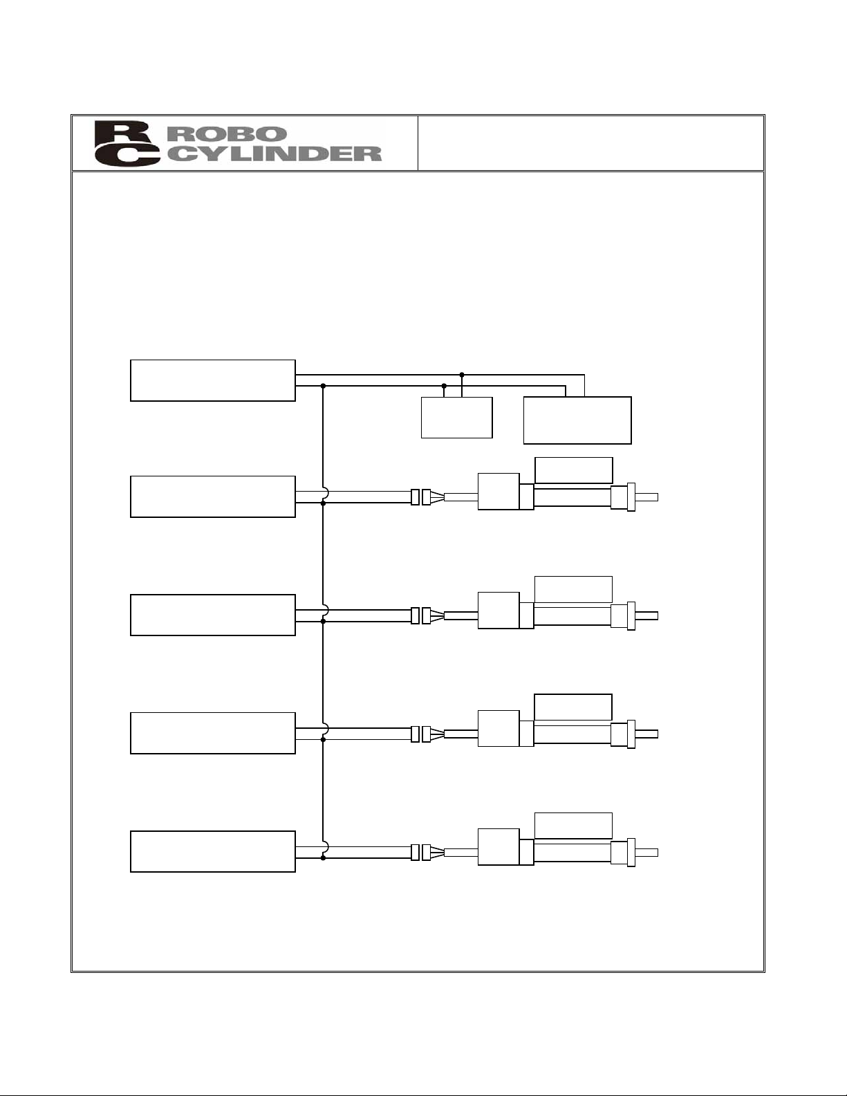
1. Using Multiple 24-V Power Supplies
If multiple 24-V power supplies are used, always connect the 0-V lines of all power supplies.
If not, damage to the controller board, SIO converter or other components may occur.
[Connection Example]
24V
0V
24V
0V
24V
0V
24V
0V
24V
0V
24-V power supply
[1]
24-V power supply
[2]
24-V power supply
[3]
24-V power supply
[4]
24-V power supply
[5]
SIO
converter
PLC
PIO unit
Actuator 1
Actuator 2
Actuator 3
Actuator 4
Page 5

CAUTION
2. PC Software and Teaching Pendant Models
This product offers new functions not available in the conventional ERC series.
To support these new functions, the communication protocol has been changed to a general Modbuscompliant protocol. Accordingly, the PC software programs and teaching pendants that have been used
with the ERC series are no longer compatible with the ERC2 series.
Select a compatible program or teaching pendant from among the models listed below.
Model nu
mber Remarks
PC software (with RS232C
communication cable)
RCM-101-MW
PC software (with USB
communication cable)
RCM-101-USB
Teaching pendant RCM-T, RCM-TD
Simple teaching pendant RCM-E
Data setting unit RCM-P
These software programs/teaching
pedants can be used with the ERC
series.
3. Backup of Latest Data
The built-in controller of this actuator uses a nonvolatile memory to store position table data and
parameters. Normally data is retained after the power has been cut off, but stored data will be lost if the
nonvolatile memory is damaged.
Regular backup of latest position table data and parameters not only ensures that your important data is
safeguarded, but it also saves the data recovery time when a need arises to replace the controller board
for some reason.
To back up your data, do one of the following:
[1] Save the data to a hard disk or other storage media from the PC software.
[2] Create a position table sheet or parameter sheet and write down the settings.
4. Pamphlet on Modbus Protocols
You can download a pamphlet compiling Modbus protocols from the operation manual download page on
IAI’s website:
website:www.intelligentactuator.com
If you wish to obtain this pamphlet, please contact your IAI sales representative.
Page 6

CE Marking
If a compliance with the CE Marking is required, please follow Overseas Standards Compliance Manual
(ME0287) that is provided separately.
Page 7

Table of Contents
Safety Guide.................................................................................................................................................. 1
1. Overview ................................................................................................................................................ 9
1.1 Introduction .................................................................................................................................. 9
1.2 Key Features and Functions...................................................................................................... 10
1.3 Differences from Air Cylinder Control ........................................................................................11
1.4 Meaning of the Model Number ..................................................................................................13
1.5 Specifications............................................................................................................................. 14
1.5.1 Correlation Diagrams of Speed and Payload Capacity – Slider Type .......................... 15
1.5.2 Correlation Diagrams of Speed and Payload Capacity – Rod Type............................. 16
1.5.3 The sound pressure level of this product does not exceed 70 dB................................ 17
1.6 Warranty ................................................................................................................................... 20
1.7 Transportation and Handling ..................................................................................................... 20
1.7.1 Handling before Unpacking .......................................................................................... 20
1.7.2 Handling after Unpacking.............................................................................................. 20
1.8 Installation Environment and Noise Elimination ........................................................................ 21
1.8.1 Installation Environment................................................................................................ 21
1.8.2 Storage Environment .................................................................................................... 21
1.8.3 Power Supply................................................................................................................ 22
1.8.4 Noise Elimination .......................................................................................................... 22
1.9 Cabling....................................................................................................................................... 24
2. Installation............................................................................................................................................ 27
2.1 Name of Each Part .................................................................................................................... 27
2.1.1 Slider Type (SA6C/SA7C)............................................................................................. 27
2.1.2 Rod Type (RA6C/RA7C)............................................................................................... 28
2.1.3 (1) Rod Type with a Single Guide (RGS6C/RGS7C).................................................... 28
(2) Rod Type with Double Guides (RGD6C/RGD7C)................................................... 28
2.2 Installation.................................................................................................................................. 29
2.2.1 Slider Type.................................................................................................................... 29
2.2.2 Rod Type.......................................................................................................................30
2.2.3 Installing the Load......................................................................................................... 32
3. Electrical Specifications ....................................................................................................................... 34
3.1 Controller ................................................................................................................................... 34
3.2 Input/Output Interfaces .............................................................................................................. 35
3.2.1 Extension Cable............................................................................................................ 36
3.3 SIO Converter (Optional)........................................................................................................... 37
4. Wiring ................................................................................................................................................... 39
4.1 Basic Configuration with SIO Converter.................................................................................... 39
4.1.1 SIO Communication Connection Using a Relay Terminal Block ..................................41
4.1.2 SIO Communication Connection Using a 4-Way Junction ........................................... 42
4.1.3 Address Assignment..................................................................................................... 43
4.2 Configuration Using a Gateway Unit ......................................................................................... 44
4.2.1 SIO Communication Connection Using a Relay Terminal Block ..................................44
4.2.2 SIO Communication Connection Using a 4-Way Junction ........................................... 45
Page 8

4.2.3 Connecting an Emergency Stop Circuit, Etc.................................................................46
5. Explanation of Operating Functions..................................................................................................... 47
5.1 Description of Position Table ..................................................................................................... 48
5.1.1 Relationship of Push Force at Standstill and Current-Limiting Value ........................... 52
5.2 Data Set in the Numerical Specification Mode .......................................................................... 54
5.3 Explanation of Functions ........................................................................................................... 54
5.3.1 Control Signals and Control Data ................................................................................. 56
5.3.2 Timings after Power On ................................................................................................62
5.3.3 Home Return Operation................................................................................................ 64
5.3.4 Positioning Operation.................................................................................................... 66
5.3.5 Push & Hold Operation ................................................................................................. 70
5.3.6 Pause............................................................................................................................ 74
5.3.7 Speed Change during Movement................................................................................. 75
5.3.8 Operation at Different Acceleration and Deceleration .................................................. 77
5.3.9 Zone Signal................................................................................................................... 78
5.3.10 Pitch Feed by Incremental Specification.......................................................................79
5.3.11 Power-Saving Mode at Standby Positions....................................................................83
6. Parameter Settings .............................................................................................................................. 84
6.1 Parameter Table ........................................................................................................................ 84
6.2 Detailed Explanation of Parameters.......................................................................................... 85
6.2.1 Parameters Relating to the Actuator Stroke Range......................................................85
6.2.2 Parameters Relating to the Actuator Operating Characteristics................................... 87
6.2.3 Parameters Relating to the External Interface.............................................................. 91
6.2.4 Servo Gain Adjustment................................................................................................. 93
7. Troubleshooting ................................................................................................................................... 95
7.1 Action to Be Taken upon Occurrence of Problem...................................................................... 95
7.2 Alarm Level Classification..........................................................................................................96
7.2.1 How to Reset Alarms ....................................................................................................96
7.3 Alarm Description and Cause/Action......................................................................................... 97
7.4 Messages Displayed during Operation Using the Teaching Pendant or PC Software............ 102
7.5 Specific Problems.................................................................................................................... 104
8. Maintenance and Inspection.............................................................................................................. 106
8.1 Inspection Items and Schedule ...............................................................................................106
8.2 Visual Inspection of Appearance ............................................................................................. 106
8.3 Cleaning................................................................................................................................... 106
8.4 Internal Check (Slider Type) .................................................................................................... 107
8.5 Internal Cleaning (Slider Type) ................................................................................................ 108
8.6 Greasing the Guide (Slider Type) ............................................................................................ 108
8.7 Greasing the Ball Screw (Slider Type).....................................................................................110
8.8 Greasing the Rod Slide Surface.............................................................................................. 111
8.9 Motor Replacement Procedure................................................................................................112
9. Operation Examples .......................................................................................................................... 114
10. Appendix ........................................................................................................................................... 115
.......................................................................................................................... 115
..........................................................................................................................115
..........................................................................................................................116
10.1 External Dimensions
10.1.1 ERC2-SA6C
10.1.2 ERC2-SA7C
Page 9

10.1.3 ERC2-RA6C
10.1.4 ERC2-RA7C
10.1.5 ERC2-RGS6C
10.1.6 ERC2-RGS7C
10.1.7 ERC2-RGD6C
10.1.8 ERC2-RGD7C
10.2
Recording of Position Table
Parameter Records
10.3
................................................................................... ....................................... 117
................................................................................... ................................ ....... 118
................................................................................... .................................... 119
................................................................................... .................................... 119
................................................................................... .................................... 120
................................................................................... ................................ .... 120
................................................................................... ............................. 121
................................................................................... ........................................... 124
Change History......................... ....................................................................................................... 125
Page 10

Page 11

Safety Guide
“Safety Guide” has been written to use the machine safely and so prevent personal injury or property
damage beforehand. Make sure to read it before the operation of this product.
Safety Precautions for Our Products
The common safety precautions for the use of any of our robots in each operation.
No.
1 Model
Operation
Description
Selection
Description
Ɣ This product has not been planned and designed for the application where
high level of safety is required, so the guarantee of the protection of
human life is impossible. Accordingly, do not use it in any of the following
applications.
1) Medical equipment used to maintain, control or otherwise affect human
life or physical health.
2) Mechanisms and machinery designed for the purpose of moving or
transporting people (For vehicle, railway facility or air navigation facility)
3) Important safety parts of machinery (Safety device, etc.)
Ɣ Do not use the product outside the specifications. Failure to do so may
considerably shorten the life of the product.
Ɣ Do not use it in any of the following environments.
1) Location where there is any inflammable gas, inflammable object or
explosive
2) Place with potential exposure to radiation
3) Location with the ambient temperature or relative humidity exceeding
the specification range
4) Location where radiant heat is added from direct sunlight or other large
heat source
5) Location where condensation occurs due to abrupt temperature
changes
6) Location where there is any corrosive gas (sulfuric acid or hydrochloric
acid)
7) Location exposed to significant amount of dust, salt or iron powder
8) Location subject to direct vibration or impact
Ɣ For an actuator used in vertical orientation, select a model which is
equipped with a brake. If selecting a model with no brake, the moving part
may drop when the power is turned OFF and may cause an accident such
as an injury or damage on the work piece.
1
Page 12

No.
Operation
Description
Description
2 Transportation Ɣ When carrying a heavy object, do the work with two or more persons or
utilize equipment such as crane.
Ɣ When the work is carried out with 2 or more persons, make it clear who is
to be the leader and who to be the follower(s) and communicate well with
each other to ensure the safety of the workers.
Ɣ When in transportation, consider well about the positions to hold, weight
and weight balance and pay special attention to the carried object so it
would not get hit or dropped.
Ɣ Transport it using an appropriate transportation measure.
The actuators available for transportation with a crane have eyebolts
attached or there are tapped holes to attach bolts. Follow the instructions
in the instruction manual for each model.
Ɣ Do not step or sit on the package.
Ɣ Do not put any heavy thing that can deform the package, on it.
Ɣ When using a crane capable of 1t or more of weight, have an operator
who has qualifications for crane operation and sling work.
Ɣ When using a crane or equivalent equipments, make sure not to hang a
load that weighs more than the equipment’s capability limit.
Ɣ Use a hook that is suitable for the load. Consider the safety factor of the
hook in such factors as shear strength.
Ɣ Do not get on the load that is hung on a crane.
Ɣ Do not leave a load hung up with a crane.
Ɣ Do not stand under the load that is hung up with a crane.
3 Storage and
Preservation
Ɣ The storage and preservation environment conforms to the installation
environment. However, especially give consideration to the prevention of
condensation.
Ɣ Store the products with a consideration not to fall them over or drop due to
an act of God such as earthquake.
4 Installation
and Start
(1) Installation of Robot Main Body and Controller, etc.
Ɣ Make sure to securely hold and fix the product (including the work part). A
fall, drop or abnormal motion of the product may cause a damage or injury.
Also, be equipped for a fall-over or drop due to an act of God such as
earthquake.
Ɣ Do not get on or put anything on the product. Failure to do so may cause
an accidental fall, injury or damage to the product due to a drop of
anything, malfunction of the product, performance degradation, or
shortening of its life.
Ɣ When using the product in any of the places specified below, provide a
sufficient shield.
1) Location where electric noise is generated
2) Location where high electrical or magnetic field is present
3) Location with the mains or power lines passing nearby
4) Location where the product may come in contact with water, oil or
chemical droplets
2
Page 13

No.
Operation
Description
4 Installation
and Start
Description
(2) Cable Wiring
Ɣ Use our company’s genuine cables for connecting between the actuator
and controller, and for the teaching tool.
Ɣ Do not scratch on the cable. Do not bend it forcibly. Do not pull it. Do not
coil it around. Do not insert it. Do not put any heavy thing on it. Failure to
do so may cause a fire, electric shock or malfunction due to leakage or
continuity error.
Ɣ Perform the wiring for the product, after turning OFF the power to the unit,
so that there is no wiring error.
Ɣ When the direct current power (+24V) is connected, take the great care of
the directions of positive and negative poles. If the connection direction is
not correct, it might cause a fire, product breakdown or malfunction.
Ɣ Connect the cable connector securely so that there is no disconnection or
looseness. Failure to do so may cause a fire, electric shock or malfunction
of the product.
Ɣ Never cut and/or reconnect the cables supplied with the product for the
purpose of extending or shortening the cable length. Failure to do so may
cause the product to malfunction or cause fire.
(3) Grounding
Ɣ The grounding operation should be performed to prevent an electric shock
or electrostatic charge, enhance the noise-resistance ability and control
the unnecessary electromagnetic radiation.
Ɣ For the ground terminal on the AC power cable of the controller and the
grounding plate in the control panel, make sure to use a twisted pair cable
with wire thickness 0.5mm
2
(AWG20 or equivalent) or more for grounding
work. For security grounding, it is necessary to select an appropriate wire
thickness suitable for the load. Perform wiring that satisfies the
specifications (electrical equipment technical standards).
Ɣ Perform Class D Grounding (former Class 3 Grounding with ground
resistance 100Ω or below).
3
Page 14

No.
4 Installation
Operation
Description
and Start
Description
(4) Safety Measures
Ɣ When the work is carried out with 2 or more persons, make it clear who is
to be the leader and who to be the follower(s) and communicate well with
each other to ensure the safety of the workers.
Ɣ When the product is under operation or in the ready mode, take the safety
measures (such as the installation of safety and protection fence) so that
nobody can enter the area within the robot’s movable range. When the
robot under operation is touched, it may result in death or serious injury.
Ɣ Make sure to install the emergency stop circuit so that the unit can be
stopped immediately in an emergency during the unit operation.
Ɣ Take the safety measure not to start up the unit only with the power turning
ON. Failure to do so may start up the machine suddenly and cause an
injury or damage to the product.
Ɣ Take the safety measure not to start up the machine only with the
emergency stop cancellation or recovery after the power failure. Failure to
do so may result in an electric shock or injury due to unexpected power
input.
Ɣ When the installation or adjustment operation is to be performed, give
clear warnings such as “Under Operation; Do not turn ON the power!” etc.
Sudden power input may cause an electric shock or injury.
Ɣ Take the measure so that the work part is not dropped in power failure or
emergency stop.
Ɣ Wear protection gloves, goggle or safety shoes, as necessary, to secure
safety.
Ɣ Do not insert a finger or object in the openings in the product. Failure to do
so may cause an injury, electric shock, damage to the product or fire.
Ɣ When releasing the brake on a vertically oriented actuator, exercise
precaution not to pinch your hand or damage the work parts with the
actuator dropped by gravity.
5 Teaching Ɣ When the work is carried out with 2 or more persons, make it clear who is
to be the leader and who to be the follower(s) and communicate well with
each other to ensure the safety of the workers.
Ɣ Perform the teaching operation from outside the safety protection fence, if
possible. In the case that the operation is to be performed unavoidably
inside the safety protection fence, prepare the “Stipulations for the
Operation” and make sure that all the workers acknowledge and
understand them well.
Ɣ When the operation is to be performed inside the safety protection fence,
the worker should have an emergency stop switch at hand with him so that
the unit can be stopped any time in an emergency.
Ɣ When the operation is to be performed inside the safety protection fence,
in addition to the workers, arrange a watchman so that the machine can
be stopped any time in an emergency. Also, keep watch on the operation
so that any third person can not operate the switches carelessly.
Ɣ Place a sign “Under Operation” at the position easy to see.
Ɣ When releasing the brake on a vertically oriented actuator, exercise
precaution not to pinch your hand or damage the work parts with the
actuator dropped by gravity.
* Safety protection Fence : In the case that there is no safety protection
fence, the movable range should be indicated.
4
Page 15

No.
Operation
Description
Description
6 Trial Operation Ɣ When the work is carried out with 2 or more persons, make it clear who is
to be the leader and who to be the follower(s) and communicate well with
each other to ensure the safety of the workers.
Ɣ After the teaching or programming operation, perform the check operation
one step by one step and then shift to the automatic operation.
Ɣ When the check operation is to be performed inside the safety protection
fence, perform the check operation using the previously specified work
procedure like the teaching operation.
Ɣ Make sure to perform the programmed operation check at the safety
speed. Failure to do so may result in an accident due to unexpected
motion caused by a program error, etc.
Ɣ Do not touch the terminal block or any of the various setting switches in
the power ON mode. Failure to do so may result in an electric shock or
malfunction.
7 Automatic
Operation
Ɣ Check before starting the automatic operation or rebooting after operation
stop that there is nobody in the safety protection fence.
Ɣ Before starting automatic operation, make sure that all peripheral
equipment is in an automatic-operation-ready state and there is no alarm
indication.
Ɣ Make sure to operate automatic operation start from outside of the safety
protection fence.
Ɣ In the case that there is any abnormal heating, smoke, offensive smell, or
abnormal noise in the product, immediately stop the machine and turn
OFF the power switch. Failure to do so may result in a fire or damage to
the product.
Ɣ When a power failure occurs, turn OFF the power switch. Failure to do so
may cause an injury or damage to the product, due to a sudden motion of
the product in the recovery operation from the power failure.
5
Page 16

No.
8 Maintenance
Operation
Description
and Inspection
Description
Ɣ When the work is carried out with 2 or more persons, make it clear who is
to be the leader and who to be the follower(s) and communicate well with
each other to ensure the safety of the workers.
Ɣ Perform the work out of the safety protection fence, if possible. In the case
that the operation is to be performed unavoidably inside the safety
protection fence, prepare the “Stipulations for the Operation” and make
sure that all the workers acknowledge and understand them well.
Ɣ When the work is to be performed inside the safety protection fence,
basically turn OFF the power switch.
Ɣ When the operation is to be performed inside the safety protection fence,
the worker should have an emergency stop switch at hand with him so that
the unit can be stopped any time in an emergency.
Ɣ When the operation is to be performed inside the safety protection fence,
in addition to the workers, arrange a watchman so that the machine can
be stopped any time in an emergency. Also, keep watch on the operation
so that any third person can not operate the switches carelessly.
Ɣ Place a sign “Under Operation” at the position easy to see.
Ɣ For the grease for the guide or ball screw, use appropriate grease
according to the Instruction Manual for each model.
Ɣ Do not perform the dielectric strength test. Failure to do so may result in a
damage to the product.
Ɣ When releasing the brake on a vertically oriented actuator, exercise
precaution not to pinch your hand or damage the work parts with the
actuator dropped by gravity.
Ɣ The slider or rod may get misaligned OFF the stop position if the servo is
turned OFF. Be careful not to get injured or damaged due to an
unnecessary operation.
Ɣ Pay attention not to lose the cover or untightened screws, and make sure
to put the product back to the original condition after maintenance and
inspection works.
Use in incomplete condition may cause damage to the product or an injury.
* Safety protection Fence : In the case that there is no safety protection
fence, the movable range should be indicated.
9 Modification
and Dismantle
Ɣ Do not modify, disassemble, assemble or use of maintenance parts not
specified based at your own discretion.
10 Disposal Ɣ When the product becomes no longer usable or necessary, dispose of it
properly as an industrial waste.
Ɣ When removing the actuator for disposal, pay attention to drop of
components when detaching screws.
Ɣ Do not put the product in a fire when disposing of it.
The product may burst or generate toxic gases.
11 Other Ɣ Do not come close to the product or the harnesses if you are a person
who requires a support of medical devices such as a pacemaker. Doing so
may affect the performance of your medical device.
Ɣ See Overseas Specifications Compliance Manual to check whether
complies if necessary.
Ɣ For the handling of actuators and controllers, follow the dedicated
instruction manual of each unit to ensure the safety.
6
Page 17
Alert Indication
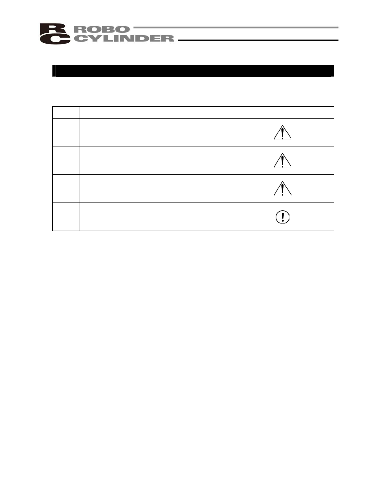
The safety precautions are divided into “Danger”, “Warning”, “Caution” and “Notice” according to the
warning level, as follows, and described in the Instruction Manual for each model.
Level Degr
Danger
Warning
Caution
Notice
This indicates an imminently hazardous situation which, if the
product is not handled correctly, will result in death or serious injury.
This indicates a potentially hazardous situation which, if the product
is not handled correctly, could result in death or serious injury.
This indicates a potentially hazardous situation which, if the product
is not handled correctly, may result in minor injury or property
damage.
This indicates lower possibility for the injury, but should be kept to
use this product properly.
ee of Danger and Damage Symbol
Danger
Warning
Caution
Notice
7
Page 18

Caution in Handling
1. Do not set speeds and accelerations/decelerations equal to or greater
than the respective ratings.
If the actuator is operated at a speed or acceleration/deceleration exceeding the allowable
value, abnormal noise or vibration, failure, or shorter life may result.
In the case of interpolated operation of combined axes, the speed and
acceleration/deceleration settings should correspond to the minimum values among all
combined axes.
2. Keep the load moment within the allowable value.
If the actuator is operated under a load equal to or greater than the allowable load moment,
abnormal noise or vibration, failure, or shorter life may result. In an extreme case, flaking
may occur.
3. Make sure to attach the actuator properly by following this instruction
manual.
Using the product with the actuator not being certainly retained or affixed may cause abnormal
noise, vibration, malfunction or shorten the product life.
8
Page 19

1. Overview
1.1 Introduction
Thank you for purchasing the Easy All-in-One ROBO Cylinder (hereinafter referred to as “ERC2-SE”).
This product retains all benefits of the conventional ERC series, while incorporating new features that provide
greater convenience and enhanced safety to the users.
Among the ERC2 Series actuators, this product can be operated via serial communication in the position number
specification mode or the direct numerical specification mode.
The following two communication patterns are supported by serial communication systems:
[1] Communicate with a host PLC, etc., via a gateway unit in various field network environments (DeviceNet,
CC-Link and Profibus).
[2] Communicate serially with a PC or PLC via a SIO converter based on the RS-232C protocol.
Please read this manual carefully and handle the product with utmost care while ensuring its correct operation.
It is advised that you also peruse the operation manual for your gateway unit as well as the Operation Manual for
Serial Communication Protocol.
When starting your system or in the event of failure, also refer to the operation manuals for the teaching pendant,
PC software and other components you are using with this product.
This manual does not cover all possible operations other than normal operations, or unexpected events
such as complex signal changes resulting from operating the product at critical timings.
Accordingly, think of any item not specifically mentioned in this manual as “prohibited.”
* We have made every effort to ensure accuracy of the information provided in this manual. Should you find an
error, however, or if you have any comment, please contact IAI.
Keep this manual in a convenient place so it can be referenced readily when necessary.
1. Overview
9
Page 20

1.2 Key Features and Functions
(1) Input/output of control signals by means of RS485 serial communication (conforming to the Modbus
protocol)
(2) 64 positioning points
(3) Variable zone output boundaries
Before, zone output boundaries were set by parameters and therefore fixed. For greater convenience, this
product permits setting of zone output boundaries in the position table. (Available in the position number
specification mode only)
Set desired boundaries to prevent contact with peripheral equipment, shorten the tact time, etc.
(4) Different acceleration and deceleration settings (Available in the position number specification mode only)
Acceleration and deceleration can be set differently in the position table.
In situations where shock and vibration upon stopping must be minimized depending on the material or
shape of the load, you can decrease only the deceleration to allow the actuator to stop along a gradual
deceleration curve.
(5) Limitation of moving speed during adjustment by trial operation
During adjustment by trial operation, the moving speed of the actuator can be limited to ensure safety.
(6) Power-saving measure
In general, pulse motors generate greater holding current than AC servo motors in a standstill state.
Accordingly, we provide a power-saving mode to conserve electricity in situations where the actuator stands
by for a long period.
1. Overview
10
Page 21
1.3 Differences from Air Cylinder Control
This section explains the key differences between an air cylinder and this controller for users who are familiar
with air cylinders but have never used a motorized cylinder before.
Refer to the table below to perform appropriate controls.
Item Air cylinder This controller
Drive method Driven by air pressure
based on electromagnetic
valve control.
Driven by a ball screw or timing belt using a pulse motor.
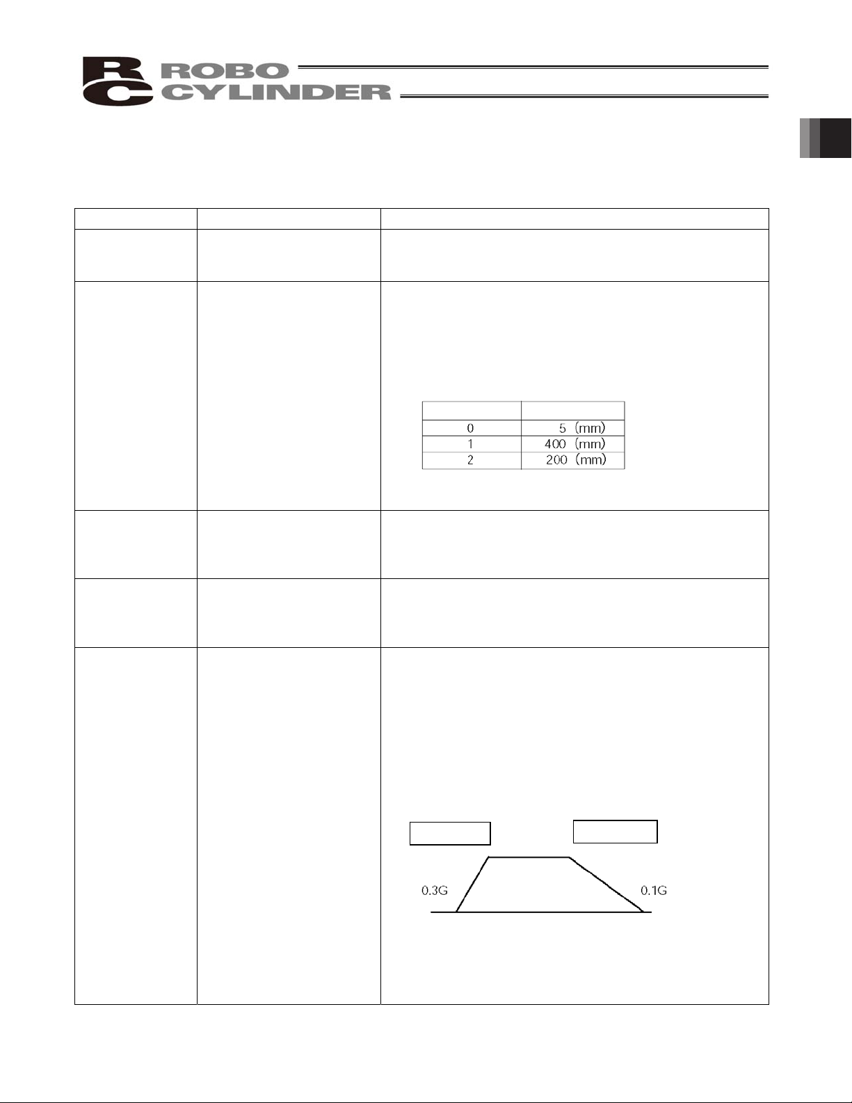
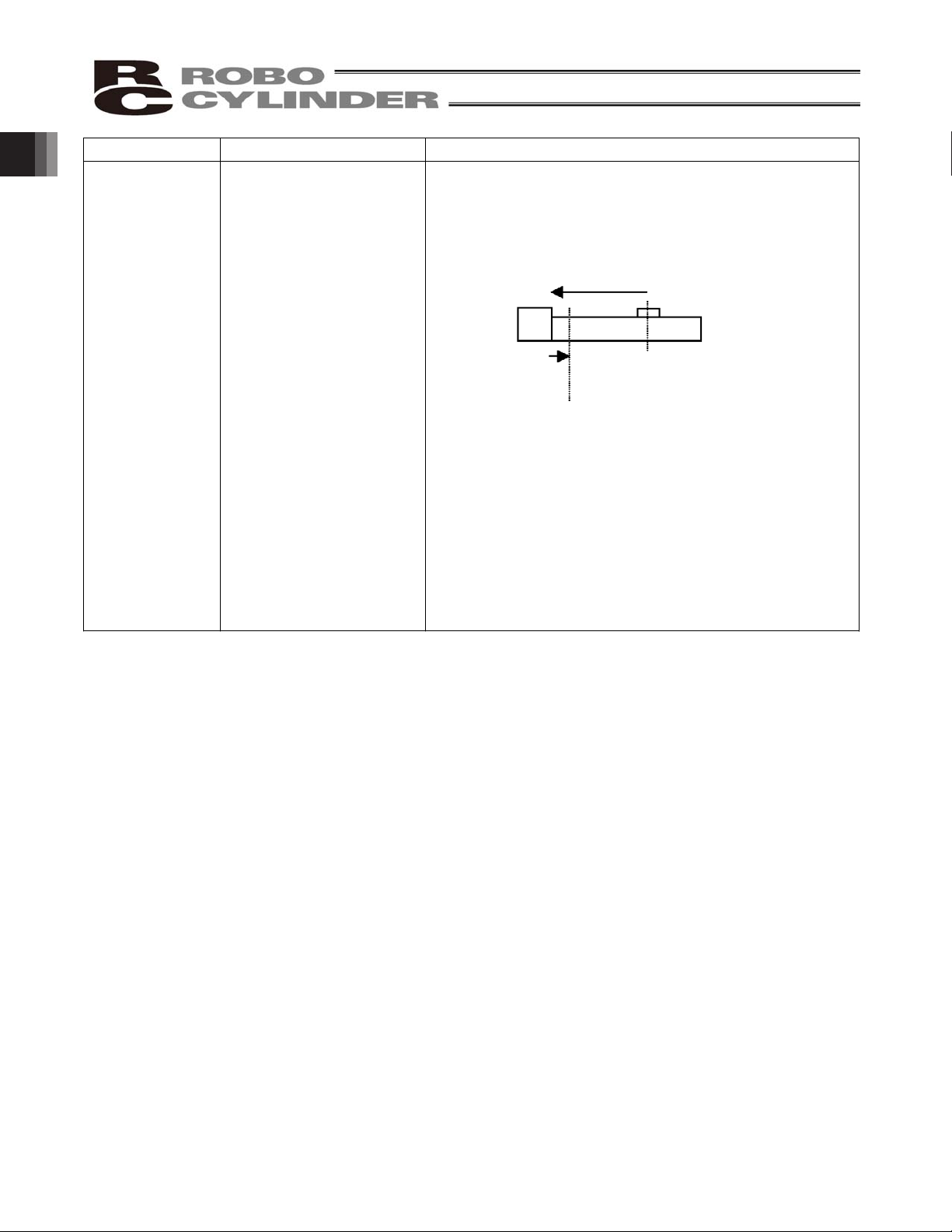
Target position
setting
Mechanical stopper
(including a shock absorber)
[1] Position number specification mode
Enter a coordinate in the [Position] field of the position table.
You can key in a desired coordinate using the number keys
on a PC (keyboard)/teaching pendant, or move the actuator
to a desired position and then write the coordinate to the
position table directly.
Example) Entries on a 400-mm actuator
[2] Numerical specification mode: Specify a desired value
directly.
Target position
detection
A reed switch or other
external detection sensor is
installed.
Whether or not the target position has been reached is
determined based on the internal coordinate information
received from the position detector (encoder).
Accordingly, no external detection sensor is required.
Speed setting Adjusted using a speed
controller.
[1] Enter a feed speed in the [Speed] field of the position
table (in mm/sec).
Initially, the default speed has been set automatically.
[2] Specify a desired value directly.
Acceleration/
deceleration
setting
In accordance with the load,
air supply volume, and
speed
controller/electromagnetic
valve performance.
[1] Enter an acceleration or deceleration in the [Acceleration]
or [Deceleration] field of the position table (in units of 0.01
G).
Reference: 1 G = Gravitational acceleration that generates
when the actuator drops freely.
Initially, the default acceleration and deceleration have been
set automatically.
[2] Specify a desired value directly.
Since acceleration and deceleration can be set finely, you
can define a gradual deceleration/acceleration curves.
Larger acceleration/deceleration values set steeper curves,
while smaller acceleration/deceleration values set more
gradual curves.
Position No. Position
Acceleration
Deceleration
Movement
start position
End position
1. Overview
11
Page 22
Item Air cylinder This
controller
Position check
upon power on
Determined using a reed
switch or other external
detection sensor.
Immediately after the power has been turned on, the current
position is indeterminable because no mechanical
coordinates are stored in the controller.
After the power is turned on, therefore, a home return
command must always be issued to establish coordinates.
[1] The actuator moves toward the mechanical end on the
motor side at the home return speed.
[2] The actuator contacts the mechanical end and reverses its
direction, moves to the home position, and then pauses.
(Note) Make sure no obstacles are present in the home return
path.
[1]
[2]
Home
position
Power
on
position
1. Overview
12
Page 23

1.4 Meaning of the Model Number
<Series name>
<Motor type>
PM: Pulse motor
<Options>
Blank: No option
B: With brake
NM: Reversed-home
specification
FT: Foot bracket (Specified
<Extension cable length>
Blank: No cable
P: 1 m
S: 3 m
M: 5 m
X: Length specification
(Example) X08 = 8 m
R: Robot cable specification
<Stroke>
50 to 600 mm
(Standard lengths are multiples of 50
mm.)
(Example) 100 = 100 mm
<I/O signal pattern>
NP: PIO-NPN specification
PN: PIO-PNP specification
SE: SIO specification
<Ball screw lead>
16: 16 mm
12: 12 mm
8: 8 mm
6: 6 mm
4: 4 mm
3: 3 mm
<Type>
Slider type
x SA6C
x SA7C
Rod type
x RA6C
x RA7C
x RGS6C
x RGS7C
x RGD6C
x RGD7C
<Encoder type>
I: Incremental
ERC2-SA6C-I-PM-12-300-SE-S-NM
1. Overview
13
Page 24
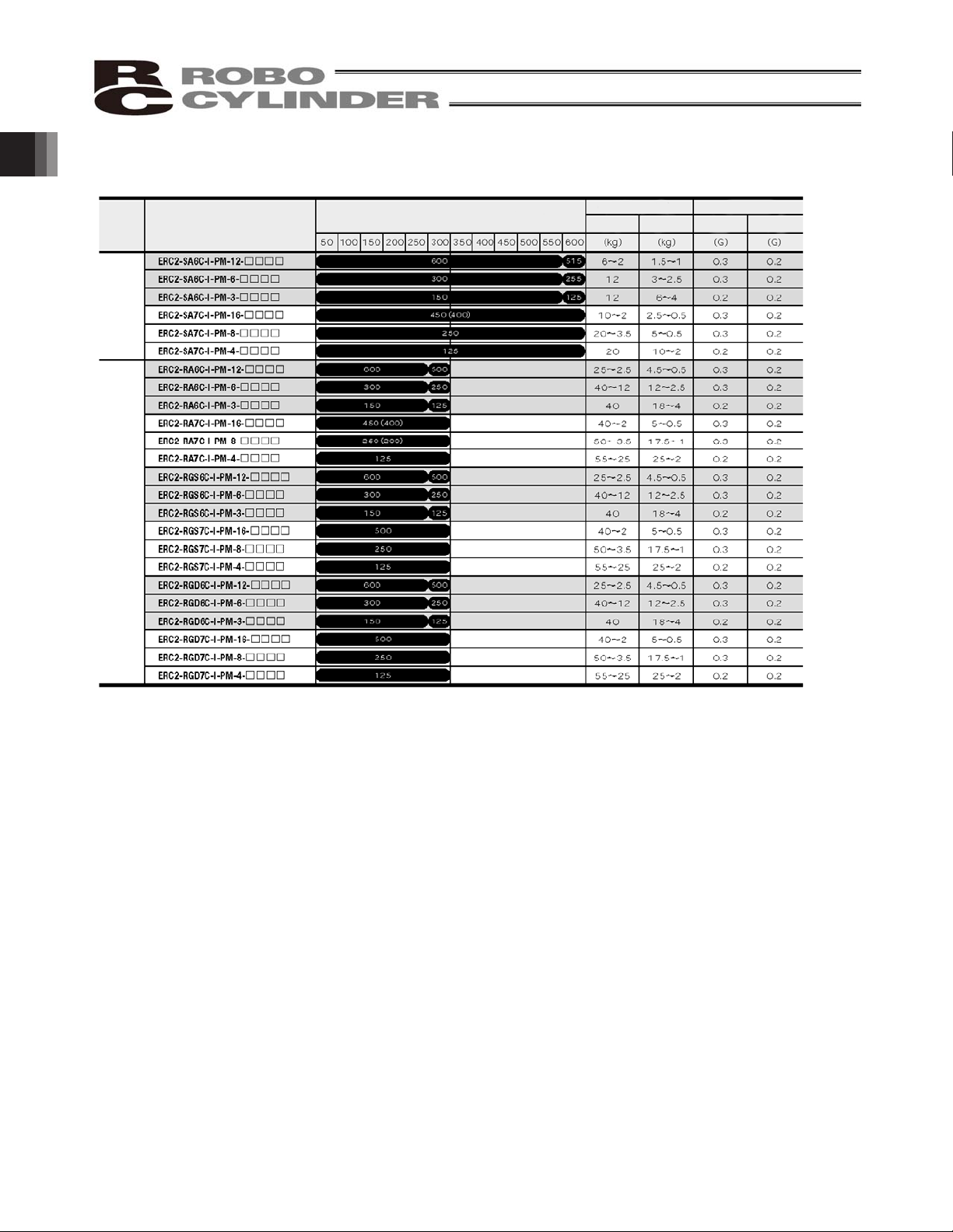
1.5 Specifications
(Note 1) The figures in blank bands indicate the maximum speeds for respective strokes. The maximum speeds during vertical operation
are shown in parentheses.
(Note 2) The payload capacity is based on operation at the rated acceleration. In the case of a guide type, find the applicable payload
capacity in the above table and subtract the weight of the guide to obtain the effective payload capacity.
Model
Stroke (mm) and maximum speed (mm/sec) (Note 1)
Payload capacity (Note
Rated acceleration
Horizontal
Vertical Horizontal Vertical
Slider type
Rod type
1. Overview
14
Page 25
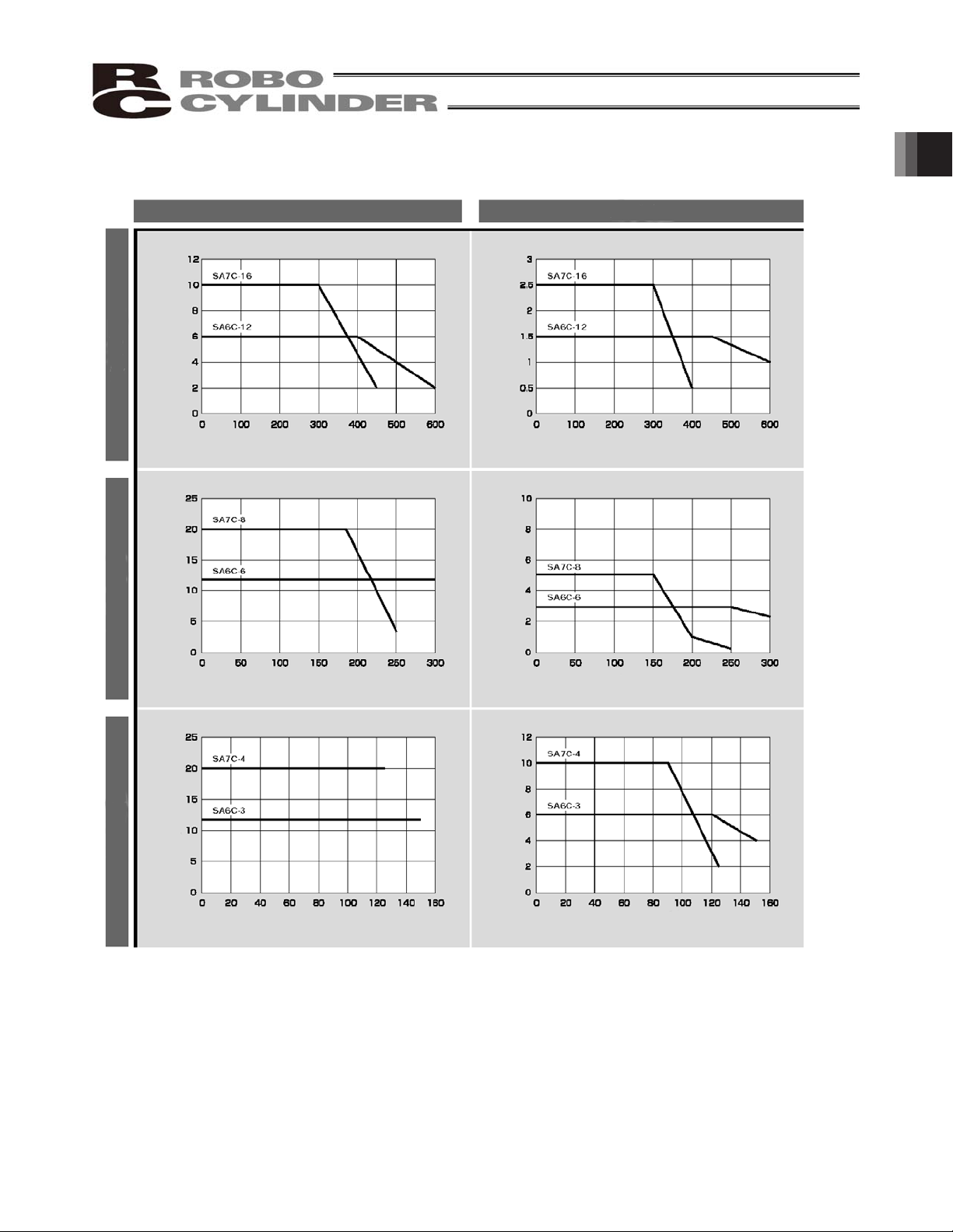
1.5.1 Correlation Diagrams of Speed and Payload Capacity – Slider Type
(Note) In the above graphs, the number after each type name indicates the lead.
Horizontal installation Ve
rtical installation
High-speed type
Load capacity (kg)
Speed (mm/sec)
Medium-speed type Low-speed type
Load capacity (kg)
Load capacity (kg)
Load capacity (kg)
Speed (mm/sec)
Speed (mm/sec) Speed (mm/sec)
Speed (mm/sec) Speed (mm/sec)
Load capacity (kg)
Load capacity (kg)
1. Overview
15
Page 26
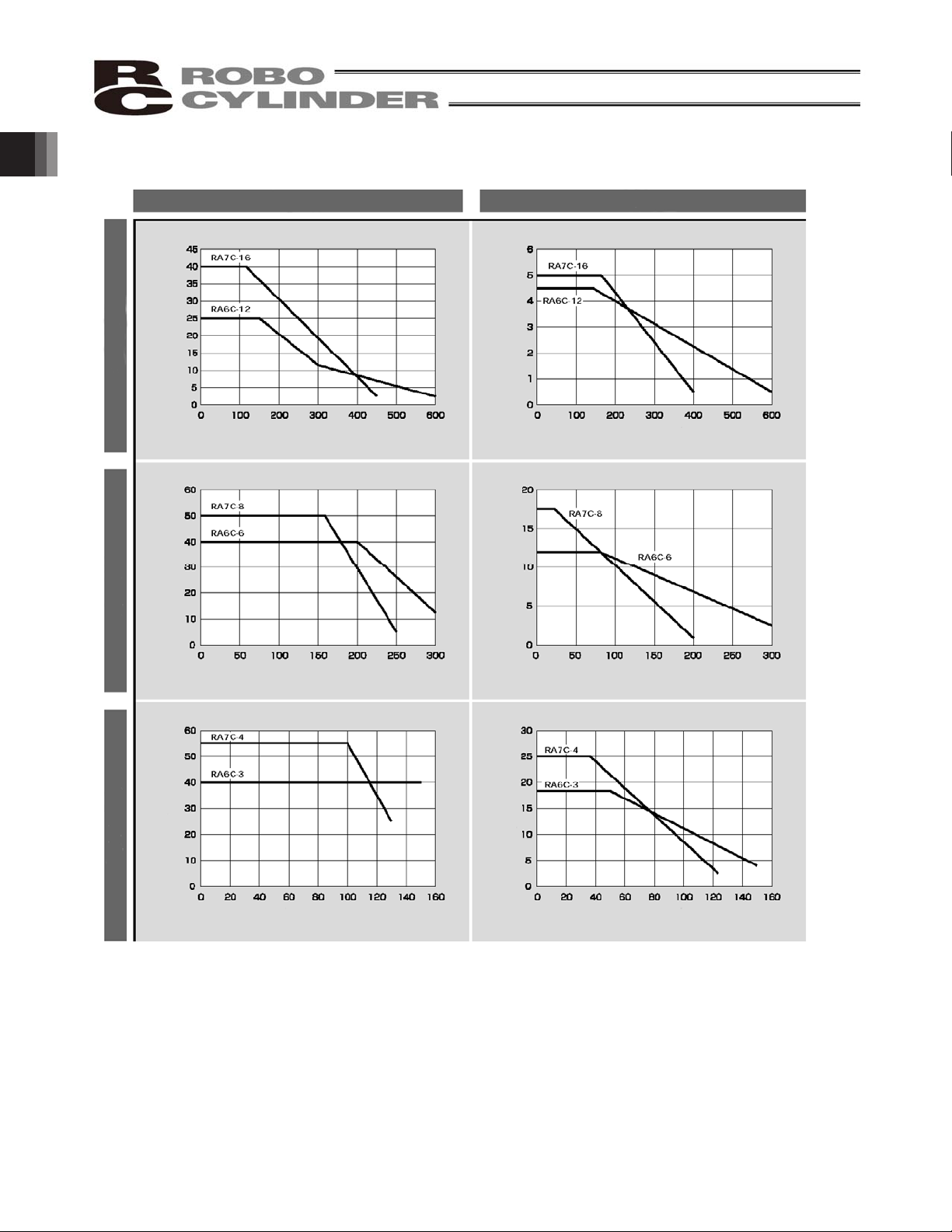
1.5.2 Correlation Diagrams of Speed and Payload Capacity – Rod Type
(Note) In the above graphs, the number after each type name indicates the lead.
Horizontal installation Ve
rtical installation
High-speed type
Load capacity (kg)
Speed (mm/sec)
Medium-speed type
Low-speed type
Load capacity (kg)
Load capacity (kg)
Load capacity (kg)
Speed (mm/sec)
Speed (mm/sec) Speed (mm/sec)
Speed (mm/sec) Speed (mm/sec)
Load capacity (kg)
Load capacity (kg)
1. Overview
16
Page 27
Load Applied to the Actuator
(1) Slider type
x Keep the load applied to the slider below the value stated in the applicable specification item.
In particular, pay attention to the moment applied to the slider, allowable overhang length and payload
capacity.
x If the slider is used in an overhang application with the load overhanging in the Y-axis direction, keep
moments Ma and Mc to one-half the rated moment or less to prevent the base from deforming.
(2) Rod type
x Keep the load applied to the rod below the value specified in the catalog.
x Make sure the center of the rod axis corresponds to the moving direction of the load.
x Application of lateral load may cause an actuator damage or breakdown.
x If the rod is to be subjected to lateral load, provide a guide or other support in
the moving direction of the load.
x Do not apply rotating torque to the rod (slide shaft).
* It will result in internal damages.
When tightening the nut at the end of the rod, secure the rod using a
wrench of size 13 (RA6C type) or 17 (RA7C type).
1.5.3 The sound pressure level of this product does not exceed 70 dB.
1. Overview
17
Page 28

1. Overview
1.6 Warranty
1 Warranty Period
One of the following periods, whichever is shorter:
y 18 months after shipment from our company
y 12 months after delivery to the specified location
2 Scope of Warranty
Our products are covered by warranty when all of the following conditions are met. Faulty products
covered by warranty will be replaced or repaired free of charge:
(1) The breakdown or problem in question pertains to our product as delivered by us or our authorized
dealer.
(2) The breakdown or problem in question occurred during the warranty period.
(3) The breakdown or problem in question occurred while the product was in use for an appropriate
purpose under the conditions and environment of use specified in the operation manual and catalog.
(4) The breakdown of problem in question was caused by a specification defect or problem, or by a
quality issue with our product.
Note that breakdowns due to any of the following reasons are excluded from the scope of warranty:
[1] Anything other than our product
[2] Modification or repair performed by a party other than us (unless we have approved such
modification or repair)
[3] Anything that could not be easily predicted with the level of science and technology available at
the time of shipment from our company
[4] A natural disaster, man-made disaster, incident or accident for which we are not liable
[5] Natural fading of paint or other symptoms of aging
[6] Wear, depletion or other expected result of use
[7] Operation noise, vibration or other subjective sensation not affecting function or maintenance
Note that the warranty only covers our product as delivered and that any secondary loss arising from a
breakdown of our product is excluded from the scope of warranty.
3 Honoring the Warranty
As a rule, the product must be brought to us for repair under warranty.
4 Limited Liability
(1) We shall assume no liability for any special damage, consequential loss or passive loss such as a
loss of expected profit arising from or in connection with our product.
(2) We shall not be liable for any program or control method created by the customer to operate our
product or for the result of such program or control method.
18
Page 29

5 Conditions of Conformance with Applicable Standards/Regulations, Etc., and
Applications
(1) If our product is combined with another product or any system, device, etc., used by the customer,
the customer must first check the applicable standards, regulations and/or rules. The customer is also
responsible for confirming that such combination with our product conforms to the applicable
standards, etc. In such a case we will not be liable for the conformance of our product with the
applicable standards, etc.
(2) Our product is for general industrial use. It is not intended or designed for the applications specified
below, which require a high level of safety. Accordingly, as a rule our product cannot be used in these
applications. Contact us if you must use our product for any of these applications:
[1] Medical equipment pertaining to maintenance or management of human life or health
[2] A mechanism or mechanical equipment intended to move or transport people (such as a
vehicle, railway facility or aviation facility)
[3] Important safety parts of mechanical equipment (such as safety devices)
[4] Equipment used to handle cultural assets, art or other irreplaceable items
(3) Contact us at the earliest opportunity if our product is to be used in any condition or environment that
differs from what is specified in the catalog or operation manual.
6 Other Items Excluded from Warranty
The price of the product delivered to you does not include expenses associated with programming, the
dispatch of engineers, etc. Accordingly, a separate fee will be charged in the following cases even during
the warranty period:
[1] Guidance for installation/adjustment and witnessing of test operation
[2] Maintenance and inspection
[3] Technical guidance and education on operating/wiring methods, etc.
[4] Technical guidance and education on programming and other items related to programs
1. Overview
19
Page 30

1.7 Transportation and Handling
1.7.1 Handling before Unpacking
Exercise due caution when transporting or handling the box containing the actuator, by not applying impact on
the box as a result of collision or dropping.
x If the box is heavy, one person should not carry it by himself.
x Place the box in a level surface.
x Do not step on the box.
x Do not place on the box any heavy object that may cause the box to deform or other object with a section
where loads will concentrate.
1.7.2 Handling after Unpacking
Once removed out of the box, hold the actuator by the frame if it is a rod type, or by the base if it is a slider type.
x When carrying the actuator, be careful not to allow it to collide with other objects. In particular, pay attention
to the front bracket, motor bracket and motor cover.
x Do not exert excessive force on each part of the actuator. In particular, pay attention to the motor cover and
cables.
x When unpacking, exercise due caution not to let the actuator drop and sustain damage to its mechanism.
x If the actuator is damaged during the shipment or any of the items is found missing, please contact IAI’s
Technical Support immediately.
Supplement) Refer to 2.1, “Name of Each Part,” for the name of each part of the actuator.
1. Overview
20
Page 31

1.8 Installation Environment and Noise Elimination
Pay due attention to the installation environment of the controller.
1.8.1 Installation Environment
The installation environment must satisfy the following conditions:
No. Use enviro
nment/condition
[1] Not exposed to direct sunlight.
[2]
The actuator is not subject to irradiated heat from a large heat source, such as a heat treatment
furnace.
[3]
Ambient temperature of 0 to 40qC.
[4] Humidity of 85% or less without condensation.
[5] Not exposed to corrosive or flammable gases.
[6] Normal environment for assembly and operation not subject to significant dust.
[7] Not exposed to oil mist or cutting fluid.
[8] Not subject to vibration exceeding 0.3 G.
[9] Not exposed to strong electromagnetic waves, ultraviolet light or radiation.
[10] Chemical resistance is not considered at all in the design of this product.
[11] The actuator and cables are not subject to electrical noise.
In general, the installation environment shall be such that the operator can work without wearing any protective
gears.
1.8.2 Storage Environment
The storage environment shall conform to the installation environment, but special caution is required to prevent
condensation if the actuator is to be stored for a long period of time.
Unless otherwise specified, the actuator is shipped without any desiccating agent placed in the box. If the
actuator is to be stored in an environment subject to condensation, provide a non-condensing measure from
outside the box or directly inside the box.
The actuator is designed to withstand storage temperatures of up to 60qC for a short period of time. If the
storage period will extend beyond one month, however, keep the storage temperature below 50qC.
1. Overview
21
Page 32

Actuator with
integrated
controller
Other
equipment
Other
equipment
Actuator with
integrated
controller
1.8.3 Power Supply
The control/motor-drive power supply specification is 24 VDC r 10% (2 A max).
1.8.4 Noise Elimination
This section explains how to eliminate noise in the use of the controller.
(1) Wiring and power supply
[1] Provide a dedicated class D grounding using a wire with a size of 0.75 mm
2
or larger.
Class D grounding Good Avoid this
grounding method.
[2] Precautions regarding wiring method
Wire extension cables separately from high-power lines for power circuits, etc. (Do not bundle them
together or place them in the same cable duct.)
1. Overview
22
Page 33

Diode
(2) Noise sources and elimination
Among the numerous noise sources, solenoid valves, magnet switches and relays are of particular concern
when building a system. Noise from these sources can be eliminated by implementing the measures
specified below.
[1] AC solenoid valves, magnet switches and relays
Measure: Install a surge absorber in parallel with the coil.
[2] DC solenoid valves, magnet switches and relays
Measure: Install a diode in parallel with the coil. Determine the diode capacity in accordance with the load
capacity.
In a DC circuit, connecting a diode in reverse polarity will damage the
diode, internal parts of the controller and/or DC power supply, so exercise
due caution.
m Point
Install a surge absorber to each coil over a minimum wiring
length.
Installing a surge absorber to the terminal block or other part
will be less effective because of a longer distance from the coil.
Surge absorber
1. Overview
23
Page 34

1.9 Cabling
x When storing a extension cable in a moving wiring duct, use a robot cable.
x In an application where the cable cannot be fixed, keep the cable from receiving a deflecting load exceeding
its own weight, use a self-standing cable hose, provide a large bending radius along the wiring path, or
provide other measure to minimize the load applied to the cable.
x Do not cut the cable for the purpose of extension, length reduction or reconnection.
If you intend to change the cable layout, please consult IAI.
1. Overview
24
Page 35

Prohibitions/Notes on Handling Cables
When designing an application system using this actuator, incorrect wiring or connection of each cable may
cause unexpected problems such as a disconnected cable or poor contact, or even a runaway system. This
section explains prohibited handling of cables. Read the information carefully to connect the cables properly.
1. Do not let the cable flex at a single point.
2. Do not let the cable bend, kink or twist. 3. Do not pull the cable with a strong force.
4. Do not let the cable receive a turning force at a
single point.
6.
Do not pinch, drop a heavy object onto or cut the
cable.
5. When fixing the cable, provide a moderate slack
and do not tension it too tight.
Steel band
(piano wire)
Bundle loosely.
Use a curly
cable.
Do not use a spiral tube
where the cable flexes
fre
q
uently.
1. Overview
25
Page 36

</59 </39
Cable
Cable track
Power line
Signal lines
(flat cable, etc.)
Duct
7. Notes on use of cable tracks
z Do not let the cable get tangled or kinked in a cable track or flexible tube. When bundling the cable, keep
a certain degree of flexibility (so that the cable will not become too taut when bent).
z Do not cause the cables to occupy more
than 60% of the space in the cable track.
z Do not store signal lines in the same cable
duct as high-power lines.
z Always use a
robot cable for
each extension
Bending radius (r)
z Use a cable track with a bending
radius (r) of 50 mm or more.
Robot cable
1. Overview
26
Page 37

LED
Non-motor end
Motor end
Right
Left
Cou
p
ling bol
t
Front bracket
Rear bracke
t
Motor bracket
Motor cover Cable
Rod
Frame
Rod end bracket
Top
Bottom
Non-motor
Screw cover Coup
ling bolt
Right
Left
Motor end
Side cove
r
LED
Top
Bottom
Fr
ont bracket
Slider
R
earbracket
Motor bracket
Rear cover
Base
Motor cover
Cable
2. Installation
2.1 Name of Each Part
2.1.1 Slider Type (SA6C/SA7C)
2.1.2 Rod Type (RA6C/RA7C)
Rear cover
2. Installation
27
Page 38

2.1.3 (1) Rod Type with a Single Guide (RGS6C/RGS7C)
(2) Rod Type with Double Guides (RGD6C/RGD7C)
Non-motor end
Coupling bolt
Right
Left
Motor end
LED
Top
Bottom
Cable
Motor cover
Rod
Frame
R
earbrac
k
et
Motor bracket
Rear cover
Guide bracket Guide bearing
Guide rod
Non-motor end
Coupling bolt
Right
Left
Motor end
LED
Top
Bottom
Cable Motor cover
Rod
Frame
Rear bracke
t
Motor bracket
Rear cover
Mounting bracket
Guide bearing
Guide rod
Guide bracket
2. Installation
28
Page 39

2.2 Installation
2.2.1 Slider Type
z Installing the actuator
The actuator-mounting surface must be a machined surface or have an equivalent flatness.
The side and bottom faces of the actuator base are parallel with the guides. If high slide precision is required,
install the actuator by using these surfaces as references.
(Note) Reduced flatness due to installation of an overhang load will cause the base to deform and inhibit
smooth movement of the slider. If the slider movement becomes heavier on the motor end or the slider
begins generating noise, correct the flatness. Otherwise, the slider mechanism may end its life
prematurely.
Install the actuator in the mounting holes provided in the
base. Secure the actuator in place using M4 hex cap bolts.
Slider type
2. Installation
29
Page 40

Hex cap bolt
Hole in flange
2.2.2 Rod Type
A rod-type actuator can be installed in the following two ways:
z Affixing with a flange
Install the actuator by tightening from the motor end side with hex cap bolts using the holes provided in the
flange.
Caution: If the actuator is installed horizontally,
exercise caution not to let the actuator
receive excessive forces.
Flange tightening bolts
Model Nominal thread size Tightening torque
RA6C M5 3.4 Nm (0.35 kgfm)
RA7C M6 5.4 Nm (0.55 kgfm)
z Affixing through holes in a flange
Caution: If the actuator is installed horizontally,
exercise caution not to let the actuator
receive excessive forces.
Flange tightening bolts
Model
Nominal
thread size
Tightening torque
RGD6C M5
Steel bolt-bearing surface: 7.3 N-m
Aluminum bolt-bearing surface: 3.4 N-m
RGD7C
M6
Steel bolt-bearing surface: 12.3 N-m
Aluminum bolt-bearing surface: 5.4 N-m
Hex cap bolt
2. Installation
30
Page 41

z Affixing with foot brackets (optional)
If optional foot brackets are used, install the foot brackets using hex cap bolts.
Foot-bracket tightening bolts
Model Nominal thread size Tightening torque
RA6C
RGS6C
RGD6C
M6 5.4 Nm (0.55 kgf-m)
RA7C
RGS7C
RGD7C
M8 11.5 Nm (1.17 kgf-m)
2. Installation
31
Page 42

2.2.3 Installing the Load
z Slider Type
Four tapped holes are provided in the slider, so affix
the load using these holes (indicated by arrows in
the figure shown to the left).
Type Slider mounting hole
SA6C, SA7C M5, depth 9 mm
Nominal thread size Tightening torque
Bolt bearing surface: steel Bolt bearing surface: aluminum
M5 7.3 Nm (0.74 kgfm) 3.4 Nm (0.35 kgfm)
The affixing method of the load shall conform to the installation method of the actuator.
In an application where the actuator is moved with the slider fixed, install the load using the tapped holes in the
slider in the same manner.
The slider has two reamed holes. Use these holes when high repeatability is required for load
installation/removal. When fine-tuning the squareness of the load, etc., make adjustment by using one of these
two reamed holes in the slider.
Type Reamed
hole
SA6C, SA7C
5, H10, depth 10 mm
2. Installation
32
Page 43

z Rod Type
A bolt is attached on the rod end bracket, so use this bolt to affix the load. (Use the supplied nut, if necessary.)
Rod end bracket
Model Rod e
nd bracket
RA6C M8, length 18 mm
RA7C M10, length 21 mm
Note) Apply a spanner wrench at the rod end bracket to
prevent the rod from receiving any rotating moment
when the load is installed.
Applying excessive rotating moment to the rod may
damage the rod.
RA6C: Width across flats 13 mm
RA7C: Width across flats 17 mm
z Rod type with a guide(s)
Model Nominal thread size
RGS6C M5
RGD6C
M5
RGS7C M6
RGD7C M6
Tightening torque
Nominal
thread size
Bolt bearing surface: steel
Bolt bearing surface:
aluminum
M5
7.3 Nxm (0.74 kgf-m) 3.4 Nxm (0.35 kgf-m)
M6
12.3 Nxm (1.26 kgf-m) 5.4 Nxm (0.55 kgf-m)
Double guides
Tapped holes are provided in the guide bracket. Affix the work
using these holes (shown by the arrows in the figures at left).
Single guide
2. Installation
33
Page 44

3. Electrical Specifications
3.1 Controller
Specification item Description
Number of controlled axes 1 axis/unit
Supply voltage
24 VDC r10%
Supply current 2 A max.
Control method Weak field-magnet vector control
Positioning command
Position number specification, numerical specification, simple
numerical/position number specification
Position number Maximum 64 points
Backup memory
Position table data and parameters are saved in nonvolatile
memory.
Serial EEPROM can be rewritten 100,000 times.
PIO None
LED indicator Servo ON (green)/Alarm (red)
Method Magnetic type
Signals 0 to 5 V, phases A/B, incremental
Encoder
Resolution 200 pul
ses/rev (multiplied by 4 in an external circuit)
Communication RS485 1 channel (terminated externally)
Communication protocol Modbus/RTU, Modbus/ASCII
Electromagnetic brake
A drive circuit is provided. 24 VDC r 10%, 0.15 A max.
Electromagnetic brake Release
The user must provide a selector switch. (Current consumption: 0.15
A max.)
Extension cable length 10 m or less
Communication cable length 100 m max. in total cable length
Isolation strength
500 VDC, 10 M:
Environment
Ambient operating
temperature
0 to 40qC
Ambient operating
humidity
85%RH or less (non-condensing)
Operating ambience Free from corrosive gases, flammable gases, oil mist, and dust.
Storage temperature
-10 to 65qC (non-freezing)
Storage humidity 90%RH or less (non-condensing)
Vibration resistance
10 to 57 Hz in XYZ directions / Pulsating amplitude: 0.035 mm
(continuous), 0.075 mm (intermittent)
Protection class IP20
Weight Approx. 25 g
External dimensions 109 W x 40 D (mm), printed circuit board
3. Electrical Specifications
34
Page 45

3.2 Input/Output Interfaces
Connector pin No. Signal name Description
1 SGA
2 SGB
3 5V
4 GND
RS485 serial communication
5 24V Control power, 24 V
6 BKR Brake release (The brake is released when 24 V, 150 mA is supplied.)
7 MPI Motor drive power, 24 V
8 GND Control power, 0 V
9 Shield
J.S.T. Mfg.
Receptacle housing
Pin contact
3. Electrical Specifications
35
Page 46

Orange
Blue
Brown
Green
Red
Gray
Yellow
Black
Shield
Signal name Wire color Wire
Control power
Brake
Shield
Shielded wire
Blue
Yellow
Red
Black
Purple
Gray
Green
Orange
Shielded wire
Standard cable
Robot cable
3.2.1 Extension Cable
This cable is a standard accessory of the controller.
(1) Power & I/O cable
(Model number: CB-ERC2-PWBIO***/CB-ERC2-PWBIO***-RB)
(Note) CB-ERC2-PWBIO***-RB indicates a robot cable.
(2) Network connection cable (Model number: CB-ERC2-CTL001)
* This cable comes with the following parts:
x e-con connector x 1
x e-con connector (with terminal resistor) x 1
x 4-way junction x 1
CN2
Manufacturer: J.S.T. Mfg.
Housing:
Contact:
Kaneko Cord
Connector cover
No connector
at cable end
Manufacturer: J.S.T. Mfg.
Model: V0.5-3
Model number nameplate
CN1
Manufacturer: J.S.T. Mfg.
Plug housing:
YLP-09V X1
Socket contact:
SYF-01T-P0.5A X9
Orange
Blue
Green
Orange
Blue
Green
Wire:
CN1
Manufacturer: J.S.T. Mfg.
Plug housing: PALR-04VF X1
Socket contact: SPAL-001T-P0.5 X4
CN2
Manufacturer: AMP
e-CON connector, 4-pin plug (green)
Model: 4-7473562-4
Wire Color Signal name Signal name Color Wire
Orange
Blue
Brown
Green
Wire Color Signal name
(Note 1) Twisted pair
(Note 2) Ground
Note 2
Note 1
3. Electrical Specifications
36
Page 47

3.3 SIO Converter (Optional)
Model number: RCB-TU-SIO-A (Vertical installation)
RCB-TU-SIO-B (Horizontal installation)
This unit is a RS232C-RS485 converter.
When multiple controllers are linked together, you can use the SIO converter to perform movement operations
and edit parameters for all axes at the same time by connecting a teaching pendant to the mini-DIN, 8-pin
connector on the converter.
z Explanation of functions
[1] Power/emergency-stop terminal block (TB2)
Provide a contact output for the emergency-stop switch on the teaching pendant (RCA-T/E).
EMG1 and EMG2 connect to the emergency-stop switch on the teaching pendant when the
PORT switch is ON, or are shorted when the PORT switch is OFF.
These terminals comprise an interlock with a safety circuit provided by the user.
Positive side of the 24-V power supply
Power supply for the teaching pendant and conversion circuit
Current consumption: 0.1 A max.
Negative side of the 24-V power supply
EMG1, EMG2
24V
0V
FG
FG of the 24-V power supply
[2] Link-connection terminal block (TB1)
A connection port for linking the controller.
“A” on the left side connects to SGA (wire color: orange/red 1) in the extension cable.
“B” on the right side connects to SGB (wire color: orange/black 1) in the extension cable.
(Note) Be sure to use twisted pair wires for the above two lines (SGA/SGB).
[3] Link connectors (J4, J5)
e-con connection ports for linking the controller. These ports accept an optional link cable (CB-RCBCTL002) directly. Note that J4 and J5 provide connections for two axes only. To connect three or more axes,
use the terminal block explained in [2].
[2] Link-connection
terminal block (TB1)
[1] Power/emergency-stop
terminal block (TB2)
[7] Monitor LEDs
[4] D-sub, 9-pin connector
[6] PORT switch
[5] Mini DIN, 8-pin connector
[3] Link connectors (J4, J5)
3. Electrical Specifications
37
Page 48

Signal
Signal
D-sub 9-pin, female
D-sub 9-pin
PC: Female
PLC: Male
[4] D-sub, 9-pin connector (RS232C)
A connection port with the PLC’s communication module. You can also connect a PC here. For the
communication cable, use a RS232C crossed cable as explained below.
[5] Mini DIN, 8-pin connector (RS485)
A connection port with the teaching pendant. For the communication cable, use the cable (with
RS232C/RS485 converter) supplied with the PC software (RCM-101-MW).
[6] PORT switch
A switch for enabling/disabling the mini-DIN connector. Set this switch to ON when a device is connected to
the mini-DIN connector, or OFF when no device is connected.
[7] Monitor LEDs
LED1 --- Lit when the controller is transmitting
LED2 --- Lit when the RS232 is transmitting
(Reference) Connection drawing of a RS232C crossed cable (generic brand)
SIO converter end
3. Electrical Specifications
38
Page 49

4. Wiring
4.1 Basic Configuration with SIO Converter
Connect a teaching pendant, PC or PLC using a SIO converter (for RS232C/RS485 conversion), as shown
below.
Caution: Do not connect any device to the mini-DIN connector and D-sub connector at the same
time. If a device is connected to these connectors at the same time, a communication
error (message level) will occur.
PC software
RS232C type <RCM-101-MW>
USB type <RCM-101-USB>
Optional
Teaching pendant
<RCM-T>
Optional
Cable length: 5 m
ERC2-SE actuator
RS232C crossed cable (generic brand)
*1 Connect the communication line from the actuator
to either TB1 or J4 (J5) on the SIO converter, as
shown below.
*2 The customer must produce an appropriate cable.
SIO converter
Vertical <RCC-TU-SIO-A>
Horizontal <RCC-TU-SIO-B>
e-CON
connector
Network connection
cable
J.S.T.
Mfg.
24-VDC control power, motor power,
brake signal, ground, shield
Power & I/O cable
J.S.T. Mfg.
(Female) (Female)
(Female)
Supplied cable
(Male)
(Male)
4. Wiring
39
Page 50

z Connection diagram
An example of serial communication connection, including an emergency stop circuit, is shown below.
Emergency stop is actuated by means of cutting off the motor drive power.
*1 The wire colors for standard cables and robot cables are
different. The colors in parentheses are for robot cables.
ERC2-SE actuator
Serial communication
Orange (Blue)
Blue (Yellow)
Brown (Red)
Green (Black)
Gray (Gray)
Red (Purple)
Black (Orange)
Yellow (Green)
Teaching pendant
EMG
pushbutton
SIO converter
TP connector
EMG reset
switch
EMG
pushbutton
Terminal
block
Power supply
The brake is released when
the contacts are closed.
I/F connector
Brake release (24 V, 150 mA)
Control power, 24 V
Motor drive power, 24 V
Shield
4. Wiring
40
Page 51

4.1.1 SIO Communication Connection Using a Relay Terminal Block
* The emergency stop circuit is the same as illustrated on the previous page.
(Note 1) If the total length of the communication cable is 10 m or longer and you experience
communication errors, connect a terminal resistor to the last axis.
(Note 2) If the actuators use different power supplies, align 0 [V] on all power supplies.
(Note 3) Connect the shielded wire of each axis to FG.
(Note 4) If the overall length of link cable exceeds 30 m, use wire of 22AWG or larger size.
Teaching pendant PC, PLC
Relay terminal
block
Actuator 1
Actuator 2
Actuator 3
One-pair shielded cable
(Fabricated by the customer)
Terminal resistor
1/2W, 220 :
SIO converter
Actuator 16
J.S.T.
Mfg.
Power & I/O cable
J.S.T.
Mfg.
24-VDC control power, motor power,
brake signal, ground, shield
(
Fabricated by the customer)
4. Wiring
41
Page 52

4.1.2 SIO Communication Connection Using a 4-Way Junction
(Note 1) If the total length of the communication cable is 10 m or longer and you experience
communication errors, connect a terminal resistor to the last axis.
(Note 2) If the actuators use different power supplies, align 0 [V] on all power supplies.
(Note 3) The gateway unit power must be the same as 0 V of the ERC2 control power.
(Note 4) Connect the shielded wire of each axis to FG.
(Note 5) If the overall length of link cable exceeds 30 m, use wire of 22AWG or larger size.
Teaching
pendant
Actuator 1
Actuator 2
Actuator 3
Actuator 16
J.S.T.
Mfg.
J.S.T.
Mfg.
24-VDC control power, motor power,
brake signal, ground, shield
e-CON connector
e-CON connector
Fabricated by the customer
Network connection cable
Power & I/O cable
PC, PLC
4. Wiring
42
Page 53

4.1.3 Address Assignment
If multiple axes are connected, a slave number must be assigned to each axis so that the host can recognize the
corresponding actuator.
Assign addresses in the setting screen of the teaching pendant or PC.
z Overview of operation on the PC
[1] Open the main window o [2] Click Setup (S) o [3] Bring the cursor to Controller Setup (C) o [4] Bring
the cursor to Assign Address (N) and click the mouse o [5] Enter an appropriate number in the
address table.
z Overview of operation on the teaching pendant RCM-T
[1] Open the User Adjustment screen o [2] Use the T key to bring the cursor to Address No. o [3] Enter
an appropriate address and press the ENTER key o [4] Enter “2” under Adjustment No. and press the
ENTER key.
z Overview of operation on the simple teaching pendant RCM-E
[1] Open the User Adjustment screen o [2] Press the ENTER key to open the screen showing Address No.
o [3] Enter an appropriate address and press the ENTER key o [4] Enter “2” under Adjustment No.
and press the ENTER key.
Refer to the operation manual for your teaching pendant or PC software for the specific operating procedure.
Caution: In the actual process of assigning addresses, the teaching pendant or PC and the target
actuator must have a one-on-one link. Therefore, disconnect the communication cables
(SGA/SGB) from other axes to tentatively provide a condition where not more than one
axis is connected.
4. Wiring
43
Page 54

4. Wiring
4.2 Configuration Using a Gateway Unit
4.2.1 SIO Communication Connection Using a Relay Terminal Block
(Note 1) If the total length of the communication cable is 10 m or longer and you experience
communication errors, connect a terminal resistor to the last axis.
(Note 2) If the actuators use different power supplies, align 0 [V] on all power supplies.
(Note 3) The gateway unit power must be the same as 0 V of the ERC2 control power.
(Note 4) Connect the shielded wire of each axis to FG.
(Note 5) If the overall length of link cable exceeds 30 m, use wire of 22AWG or larger size.
PC software
RS232C type <RCM-101-MW>
USB type <RCM-101-USB>
Optional
Teaching
pendant
Relay terminal
block
Actuator 1
Actuator 2
Actuator 3
One-pair shielded cable
(Fabricated by the customer)
Terminal resistor
1/2W, 220 :
Actuator 16
Gateway
unit
J.S.T.
Mfg.
J.S.T.
Mfg.
24-VDC control power, motor power,
brake signal, ground, shield
Fabricated by the customer
Power & I/O cable
44
Page 55

4.2.2 SIO Communication Connection Using a 4-Way Junction
(Note 1) If the total length of the communication cable is 10 m or longer and you experience
communication errors, connect a terminal resistor to the last axis.
(Note 2) If the actuators use different power supplies, align 0 [V] on all power supplies.
(Note 3) The gateway unit power must be the same as 0 V of the ERC2 control power.
(Note 4) Connect the shielded wire of each axis to FG.
(Note 5) If the overall length of link cable exceeds 30 m, use wire of 22AWG or larger size.
PC software
RS232C type <RCM-101-MW>
USB type <RCM-101-USB>
Optional
Teaching
pendant
Actuator 1
Actuator 2
Actuator 3
Actuator 16
Gateway
unit
J.S.T.
Mfg.
J.S.T.
Mfg.
4-way junction
e-CON connector
24-VDC control power, motor power,
brake signal, ground, shield
Fabricated by the customer
Network connection cable
Power & I/O cable
4. Wiring
45
Page 56

4.2.3 Connecting an Emergency Stop Circuit, Etc.
Emergency stop is actuated by means of cutting off the motor drive power.
*1 The wire colors for standard cables and robot cables are
different. The colors in parentheses are for robot cables.
(Note 1) The gateway unit power must be the same as 0 V of the ERC2 control power.
Serial communication
ERC2-SE actuator
Teaching pendant
EMG
pushbutton
Gateway unit
TP connector
EMG reset
switch
EMG
pushbutton
Power supply
The brake is released when
the contacts are closed.
I/F connector
Brake release (24 V, 150 mA)
Control power, 24 V
Motor drive power, 24 V
Shield
Gateway
p
owe
r
Port
switch
Orange (Blue)
Blue (Yellow)
Brown (Red)
Green (Black)
Gray (Gray)
Red (Purple)
Black (Orange)
Yellow (Green)
4. Wiring
46
Page 57

5. Explanation of Operating Functions
ERC2-SE actuators support two operation modes: [1] “position number specification mode” in which the actuator
is operated by specifying position numbers, and [2] “numerical specification mode” in which the actuator is
operated by directly specifying values relating to the intended operation.
To move the actuator to a specified position in the “position number specification mode,” basically a position
table must be created in advance by entering the target position in the “Position” field.
The target position can be specified as an absolute distance from the home (absolute mode), or as an
incremental travel from the current position (incremental mode).
Once the target position is entered, other fields will be automatically populated with the defaults set by the
applicable parameters.
The defaults set in the respective fields vary depending on the actuator characteristics.
Additionally, ERC2-SE actuators can be operated over a field network or via RS232C serial communication.
Accordingly, also refer to the operation manual for your gateway unit as well as the Operation Manual for Serial
Communication Protocol.
5. Explanation of Operating Functions
47
Page 58

Position Speed Acceleration Deceleration Push Threshold
Positioning
band
Zone+ Zone–
Acceleration/
deceleration
mode
Incremental
Command
mode
Standstill
mode
Comment
5.1 Description of Position Table
Create a position table using the PC software or teaching pendant. Refer to the operation manual for the PC
software or teaching pendant you are using.
This section explains the position table by using the PC software screen as an example.
(The displayed items are different on the teaching pendant.)
(1) No.
x Indicate the position data number.
(2) Position
x Enter the target position to move the actuator to, in [mm].
Absolute mode: Enter the distance to the target actuator position
from the actuator’s home.
Incremental mode: Enter the distance to the target actuator position
from the current position by assuming a movement
by constant pitch feed.
(3) Speed
x Enter the speed at which the actuator will be moved, in [mm/sec].
The default value varies depending on the actuator type.
Absolute mode The target is 30 mm from the home.
Incremental mode +10 mm from the current position.
Incremental mode -10 mm from the current position.
Position
* On the teaching pendant screen, this sign
indicates that the position is specified in the
incremental mode.
5. Explanation of Operating Functions
48
Page 59

(4) Acceleration/Deceleration
x Enter the acceleration/deceleration at which the actuator will be
moved, in [G].
Basically, you should set values within the rated range specified in the
catalog.
The input range is greater than the rated range in the catalog, in order
to accommodate situations where you want to “shorten the tact time
when the load is much smaller than the rated transferring mass.”
If the load vibrates during acceleration/deceleration and causes
problem, decrease the set values.
Increasing the set value makes acceleration/deceleration quicker, while
decreasing the set value makes acceleration/deceleration more gradual.
Caution: When setting the speed and acceleration/deceleration, refer to 1.5, “Specifications” and
enter appropriate values that will prevent the actuator from receiving excessive impact or
vibration, by considering the installation conditions and shape of the load. Increasing the
speed and acceleration/deceleration changes the transferring mass significantly, and the
actuator characteristics also vary from one model to another. Therefore, consult IAI’s
Sales Engineering Section for the maximum limits that can be entered in your specific
application.
(5) Push
x Select “positioning operation” or “push & hold operation.”
The factory setting is “0.”
0: Normal po
sitioning operation
Other than 0: Push & hold operation (The set value defines the
current-limiting value.)
(6) Threshold
x This field is not used for this controller.
The factory setting is “0.”
(7) Positioning band
x The meaning of the positioning band varies between “positioning
operation” and “push & hold operation.”
“Positioning operation”
The set value defines the distance before
the target position at which the position
complete signal will turn ON.
Increasing the positioning band quickens
the start of the next operation in the
sequence, meaning that the tact time can
be reduced. Set an appropriate value
based on the overall balance of your
system.
Speed
A
cceleration Deceleration
Time
Starting
position
Target
position
The position complete
signal turns ON here.
Positioning band
Target
position
5. Explanation of Operating Functions
49
Page 60

“Push & hold operation”
The set value defines the maximum distance the actuator will push the work
part in the push & hold mode upon reaching the target position.
Consider the mechanical variations of the work part and set an appropriate
positioning band so that positioning will not complete before the actuator
contacts the work part.
(8) Zone+/–
x Define the zone in which the zone output signal turns ON.
For added flexibility, different values can be set for each target
position.
[Setting example]
The position complete signal turns ON here, because the
actuator has contacted the load and the controller has
determined that the push & hold operation has completed.
Push
speed
Positioning band
(Maximum push distance)
Target position
Position Zone+ Zone– Comment
Movement command to position No.
Zone output signal
Home
Target position
Target position
+ limit
Movement command to position No.
Zone output signal
Speed
+ limit
- limit
5. Explanation of Operating Functions
50
Page 61

(9) Acceleration/deceleration
mode
x This field is not used for this controller.
The factory setting is “0.”
(10) Incremental
x This setting defines whether to use the absolute mode or incremental
mode.
The factory setting is “0.”
0: Absolute mode
1: Incremental mode
(11) Command mode
x This field is not used for this controller.
The factory setting is “0.”
(12) Standstill mode
x This field is not used for this controller.
The factory setting is “0.”
The power-saving mode to be applied while the actuator is standing
by is set by parameter No. 53.
The full servo control mode can be selected by setting “4” in this field.
Full servo control mode
The pulse motor is servo-controlled to reduce the holding current (standstill current that flows after completion
of positioning).
Although the exact degree of current reduction varies depending on the actuator model, load condition, etc.,
the holding current decreases to approx. one-half to one-fourth.
Since the servo remains on, no position deviation occurs.
The actual holding current can be checked in the current monitor screen of the PC software.
To enable this mode, set “4” in this field.
5. Explanation of Operating Functions
51
Page 62

5.1.1 Relationship of Push Force at Standstill and Current-Limiting Value
When performing operation in the push & hold mode, enter the current-limiting value (%) in the push column of
the position table.
Determine the current-limiting value (%) from the push force to be applied to the work part at standstill.
The graphs below illustrate the relationship of push force at standstill and current-limiting value for each actuator
type:
z Slider type
(1) SA6C type (2
) SA7C type
Low-speed type Low-speed type
(Lead: 3 mm) (Lead:
4 mm)
Medium-speed type Medium-spee
d type
(Lead: 6 mm) (Lead: 8 mm)
High-speed type High-spee
d type
(Lead: 12 mm) (L
ead: 16 mm)
Caution: The precision of push force at standstill is not guaranteed. The above graphs are provided for
reference purposes only. If the push force is too small, malfunction may occur during push &
hold operation due to slide resistance, etc., so exercise caution.
The maximum current-limiting value is shown in the above graphs. The minimum value is 20%.
Push force (N)
Push force (N)
Current-limiting value (%) Current-limiting value (%)
Push force (N)
Push force (N)
Push force (N)
Push force (N)
Current-limiting value (%) Current-limiting value (%)
Current-limiting value (%) Current-limiting value (%)
5. Explanation of Operating Functions
52
Page 63

z Rod type
(1) RA6C type (2
) RA7C type
Low-speed type Low-speed
type
(Lead: 3 mm) (Lead:
4 mm)
Medium-speed type Medium-spee
d type
(Lead: 6 mm) (Lead: 8 mm)
High-speed type High-spee
d type
(Lead: 12 mm) (L
ead: 16 mm)
Caution: The precision of push force at standstill is not guaranteed. The above graphs are provided
for reference purposes only. If the push force is too small, malfunction may occur during
push & hold operation due to slide resistance, etc., so exercise caution.
The maximum current-limiting value is shown in the above graphs. The minimum value is
20%.
Push force (N)
Push force (N)
Current-limiting value (%) Current-limiting value (%)
Push force (N)
Push force (N)
Push force (N)
Push force (N)
Current-limiting value (%) Current-limiting value (%)
Current-limiting value (%) Current-limiting value (%)
5. Explanation of Operating Functions
53
Page 64

5.2 Data Set in the Numerical Specification Mode
When the actuator is operated in the numerical specification mode, specify data relating to the intended
operation (target position, speed, acceleration/deceleration, positioning band, current-limiting value during push
& hold operation, etc.) directly. Take note that the position table may or may not be required depending on the
operation mode.
For details, refer to the Operation Manual for Gateway Unit and the Operation Manual for Serial Communication
Protocol.
5.3 Explanation of Functions
The table below lists the key functions available on ERC2-SE actuators in the position number specification
mode and the numerical specification mode, respectively.
5. Explanation of Operating Functions
54
Page 65

46
ERC2-SE Function List
{: Direct control, ': Indirect control, X: Not available
Position number specification mode Numerical specification mode
DeviceNet gateway CC-Link gateway
Serial
communication
Gateway
Position number
specification mode
Serial
communication
Direct numerical
specification mode
Command
specification mode
Position data limited
mode
Normal positioning
mode
Push & hold mode
Command
specification mode
Home return
operation
{ { { { { { { { {
Positioning
operation
' Specify a
position number
in the position
table.
' Same as on the
left
{ Specify position
data directly.
{ Specify position
data directly.
{
Specify position
data directly.{Specify a
position number
in the position
table.
{ Specify position
data directly.
{ Specify position
data directly.
{ Specify position
data directly.
{
Specify position
data directly.
{ Specify a position
number in the
position table.
Speed setting
' Set in the
position table.
' Same as on the
left
{ Specify directly
as a numerical
value.
{ Specify directly as
a numerical value.
' Set in the
position table.
' Set using a
parameter.
{ Specify directly as
a numerical
value.
{ Specify directly as
a numerical value.
' Set in the
position table.
Acceleration/
deceleration setting
' Set acceleration
and deceleration
differently in the
position table.
' Same as on the
left
{
Specify an
acceleration/
deceleration
directly as a
numerical value.
{
Specify an
acceleration/
deceleration directly
as a numerical
value.
' Set
acceleration
and
deceleration
separately in
the position
table.
{
Set an
acceleration/
deceleration using
a parameter.
{
Specify an
acceleration/
deceleration
directly as a
numerical value.
{
Specify an
acceleration/
deceleration directly
as a numerical value.
' Set in the
position table.
Operation by setting
acceleration and
deceleration
differently
' Set acceleration
and deceleration
differently in the
position table.
' Same as on the
left
{
Acceleration/
deceleration data is
accepted when
positioning is started.
To specify a
deceleration different
from an acceleration,
therefore, change the
acceleration/deceleratio
n data while the
actuator is moving, and
then restart the
operation.
{
Acceleration/
deceleration data is
accepted when
positioning is started. To
specify a deceleration
different from an
acceleration, therefore,
change the
acceleration/deceleration
data while the actuator is
moving, and then restart
the operation.
' Set
acceleration
and
deceleration
separately in
the position
table.
X Since an
acceleration/deceler
ation is set by a
single parameter,
acceleration and
deceleration cannot
be set differently.
{
Acceleration/
deceleration data is
accepted when
positioning is started. To
specify a deceleration
different from an
acceleration, therefore,
change the
acceleration/deceleratio
n data while the actuator
is moving, and then
restart the operation.
{
Acceleration/
deceleration data is
accepted when positioning
is started. To specify a
deceleration different from
an acceleration, therefore,
change the
acceleration/deceleration
data while the actuator is
moving, and then restart
the operation.
' Set acceleration
and deceleration
separately in the
position table.
Pitch (incremental)
feed
' Set in the
position table.
' Same as on the
left
{ Change bit 2 of
the CTLF control
flag to “1” to perform
incremental
operation.
X
No direct command is
available to process a
pitch feed request.
Program the host PLC to
add or subtract a constant
travel to/from the current
position and then issue a
position command.
' Set in the
position table.
X
No direct command
is available to process a
pitch feed request.
Program the host PLC
to add or subtract a
constant travel to/from
the current position and
then issue a position
command.
X
No direct command is
available to process a
pitch feed request.
Program the host PLC to
add or subtract a
constant travel to/from
the current position and
then issue a position
command.
X
No direct command is
available to process a
pitch feed request.
Program the host PLC to
add or subtract a constant
travel to/from the current
position and then issue a
position command.
' Set in the
position table.
Push & hold
operation
' Set in the
position table.
' Same as on the
left
{
{ Specify position
data directly.
' Set in the
position table.
X X
{
' Set in the
position table.
Speed change
during movement
' Combine two or
more position
numbers.
' Same as on the
left
{
Speed data is
accepted when
positioning is started.
To change the speed
during movement,
therefore, change the
speed while the
actuator is moving, and
then restart the
operation.
{
Speed data is
accepted when
positioning is started. To
change the speed during
movement, therefore,
change the speed while
the actuator is moving,
and then restart the
operation.
' Combine two or
more position
numbers.
X
{
Speed data is
accepted when
positioning is started. To
change the speed during
movement, therefore,
change the speed while
the actuator is moving,
and then restart the
operation.
{
Speed data is accepted
when positioning is
started. To change the
speed during movement,
therefore, change the
speed while the actuator is
moving, and then restart
the operation.
' Combine two or
more position
numbers.
Pause
{ { { { { { { { {
Zone signal { Zone signals are
set in the position
table or using user
parameters.
PZONE, ZONE1
and ZONE2 can be
output.
{ Zone signals are
set using user
parameters. ZONE1
and ZONE2 can be
output.
{ Zone signals are
set using user
parameters. ZONE1
and ZONE2 can be
output.
X
This function is not
available for simple
numerical
specification axes
Positioner operation: O(Depending on the
PIO pattern)
X
X X
This function is not
available for simple
numerical specification
axes.
Positioner operation: O
(Depending on the PIO
pattern)
Power-saving mode
{
The “full servo
control” power-saving
mode can be selected
using parameter No. 53.
(The automatic servo-
off mode cannot be
selected.)
{
Same as on the left
{
Same as on the left
{
Same as on the left
{
Same as on the
left
{
Same as on the left
{
Same as on the left
{
Same as on the left
{
Same as on the left
Position table Required Required Not required Not required Required Not required Required Required Required
5. Explanation of Operating Functions
55
Page 66

5.3.1 Control Signals and Control Data
To operate the actuator via serial communication, the internal 16-bit memory (Modbus registers and statuses) of
the controller must be written/read. The key signals and symbols used in these operations are explained below.
For details, refer to the Operation Manual for Serial Communication Protocol.
(1) Controller input signals
(PLC o Controller)
Register
Bit
address
Bit
position
Signal
symbol
Signal name Description
15 - - -
0401H 14 SFTY
Safety speed
command
When this bit is “0,” the safety speed set by
the parameter is disabled. When the bit is
“1,” the safety speed is enabled.
13 - - -
0403H 12 SON
Servo ON
command
The servo is off when this bit is “0” and on
when the bit is “1.”
11
to
9
- - -
0407H 8 RES Alarm reset
The “0” status of this bit indicates a normal
condition. Present alarms will be reset at
the “0” o “1” edge of this bit.
7 - - -
6 - - -
040AH 5 STP Pause command
The “0” status of this bit indicates a normal
condition. When this bit changes to “1,” the
actuator will pause (decelerate to a stop).
040BH 4 HOME
Home return
command
Home return operation will be performed at
the “0” o “1” edge of this bit.
040CH 3 CSTP Positioning start
The “0” status of this bit indicates a normal
condition. The actuator will start moving to
the target position specified by the
applicable position number at the “0” o “1”
edge of this bit.
Device
control
register
DRG1
Address
0D00H
[Common]
2
to
0
- - -
(Note) The meanings of [Common], [POS specification] and [Numerical specification] in the “Register” field are
explained below:
x [Common]: The re
gister is used in both the position number specification mode and the
numerical specification mode.
x [POS specification]: The register is used in the position number specification mode.
x [Numerical specification]: The register is used in the numerical specification mode.
5. Explanation of Operating Functions
56
Page 67

(PLC o Controller)
Register
Bit
address
Bit
position
Signal
symbol
Signal name Description
15
to
6
- - -
043AH 5 PC32 -
043BH 4 PC16 -
043CH 3 PC8 -
043DH 2 PC4 -
043EH 1 PC2 -
Position
number
specification
register
POSR
Address
0D03H
[POS
specification]
043FH 0 PC1 -
Specify
a command position number using
a 6-bit binary code.
Positioning operation will start when the
positioning start signal bit CSTR is
changed to “1.”
-
15
to
6
- - -
- 5 PC32 -
- 4 PC16 -
- 3 PC8 -
- 2 PC4 -
- 1 PC2 -
Position
number
specification
register
POSR
Address
9800H
[POS
specification]
- 0 PC1 -
This
register is the same as the one
explained above, except that with this
register, positioning operation will start the
moment a command position number is
written.
There is no need to change the positioning
start signal bit CSTR to “1.”
5. Explanation of Operating Functions
57
Page 68

(PLC o Controller)
Register Address
Description
PCMD
Position
data
specification
[Numerical
specification]
INP
Positioning
band
specification
[Numerical
specification]
VCMD
Speed
specification
[Numerical
specification]
A
CMD
A
cceleration/
deceleration
[Numerical
specification]
Upper
Lower
Sign
Signed 32-bit integer (unit: 0.01 mm)
Setting range: FFF0BBC1H to 000F423FH (-999999 to 999999)
x A negative value is indicated by a 2’s complement. Accordingly, the most
significant bit becomes “1.”
Positioning operation will start when the lower word (9901H) of this register is
rewritten.
Upper
Lower
Upper
Lower
32-bit integer (unit: 0.01 mm)
Setting range: 0H to 000F423FH (0 to 999999)
In positioning operation, this register sets a band within which a completion of
positioning is detected.
In push & motion operation (the push & motion operation must be specified
using the CTLF flag), this register sets a push band.
32-bit integer (unit: 0.01 mm/sec)
Setting range: 0H to 000F423FH (0to 999999)
This register specifies a moving speed. Movement will start when the lower
word (9905H) of this register is rewritten.
16-bit integer (unit: 0.01G), setting range: 0H to 012CH (0 to 300)
If a value exceeding the default acceleration/deceleration is set in parameter
No. 9, an alarm will generate the moment the actuator starts moving.
Movement will start when this register is rewritten.
5. Explanation of Operating Functions
58
Page 69

(PLC o Controller)
(Note) Set in a range of 20% to 70% (33H to B3H) if the actuator imposes limitations.
Register Address De
scription
Currentlimiting value
during push
& hold
operation
[Numerical
specification]
CTLF
Control flag
[Numerical
specification]
16-bit integer (unit: %, setting range: 00H to FFH/ 0 to 100 %) (Note)
Movement will start when this register is rewritten.
This flag sets a bit pattern to specify operation settings.
[1] Bit 1 (b1) 0: Normal operation 1: Push & hold operation
[2] Bit 2 (b2) 0: The push direction after completion of approach operation
represents the forward direction.
1: The push direction after completion of approach operation
represents the reverse direction.
[3] Bit 3 (b3) 0: Normal operation 1: Incremental operation
5. Explanation of Operating Functions
59
Page 70

(2) Controller output signals
(Controller o PLC)
Register
Bit
address
Bit
position
Signal
symbol
Signal name Description
0100H 15 EMGS
Emergency stop
status
An emergency stop is being actuated when
this bit is “1.”
0101H 14 SFTY
Safety speed
enabled
The safety speed is enabled when this bit
is “1.”
0102H 13 PWR Controller ready The controller is ready when this bit is “1.”
0103H 12 SV Servo ready
Operation can be performed at any time
(the servo is on) when this bit is “1.”
0104H 11 PSFL
Missed work part
during push &
hold operation
The actuator has missed the work part
during push & hold operation, when this bit
is “1.”
0105H 10 ALMH
Major failure
status
An alarm is present that inhibits
continuation of operation, when this bit is
“1.”
0106H 9 ALML
Minor failure
status
An alarm is present that permits
continuation of operation, when this bit is
“1.”
8
to
6
- - -
010AH 5 STP
Pause command
active
A pause command is being executed when
this bit is “1.”
010BH 4 HEND
Home return
completion
Home return has completed when this bit is
“1.”
010CH 3 PEND Position complete
Positioning has completed when this bit is
“1.”
Device status
register
DSS1
Address
9005H
[Common]
2
to
0
- - -
15
to
12
- - -
0124H 11 GHMS Homing
Home return operation is currently in
progress when this bit is “1.”
0123H 10 PUSH
Pushing &
holding
Push & hold operation is currently in
progress when this bit is “1.”
9
to
6
- - -
012AH 5 MOVE Moving
The actuator is moving (during home
return, push & hold operation, etc.) when
this bit is “1.”
Expansion
device status
register
DSSE
Address
9007H
[Common]
4
to
0
- - -
5. Explanation of Operating Functions
60
Page 71

(Controller o PLC)
Register
Bit
address
Bit
position
Signal
symbol
Signal name Description
15
to
9
- - -
0147H 8 PZONE
Position zone
output
If individual zone boundaries are set in the
position table, this bit will turn “1” when the
current position enters the range specified
by the boundaries.
7
to
2
- - -
014EH 1 ZONE2
Zone output 2 This bit will turn “1” when the current
position enters the range specified by the
zone boundary 2 parameters.
Zone status
register
ZONS
Address
9013H
[Common]
014FH 0 ZONE1
Zone output 1 This bit will turn “1” when the current
position enters the range specified by the
zone boundary 1 parameters.
15
to
6
- - -
013AH 5 PM32
013BH 4 PM16
013CH 3 PM8
013DH 2 PM4
013EH 1 PM2
Position
number
status
register
POSS
Address
9014H
[POS
specification]
013FH 0 PM1
A completed position number is output
using a 6-bit binary code.
(Controller o PLC)
Register Address Description
PNOW
Current
position
[Numerical
specification]
The current position is indicated by a signed 32-bit intege
r
(unit: 0.01 mm).
A
negative value is indicated by a 2’s complement. Accordingly, the most significant bit
becomes “1.”
Upper
Lower
Sign
5. Explanation of Operating Functions
61
Page 72

5.3.2 Timings after Power On
Follow the procedure below to turn on the power after confirming that the slider or rod is not contacting a
mechanical end nor the load is contacting any peripheral equipment:
[1] Cancel the emergency stop or turn on the motor drive power.
[2] Supply the 24-VDC controller power.
If 24 VDC is supplied in a condition where no emergency stop is actuated, the servo will be turned on
automatically in the controller.
[3] Initial setting of minimum parameter(s) required
(Example) x To change the feed speed during teaching:
Change parameter No. 35 (Safety speed).
[4] Using a PC or teaching pendant to set optimal values in the “Position,” “Speed,” “Acceleration” and
“Deceleration” fields, etc., of the position table.
Caution: When the power is turned on while an emergency stop is actuated, and then the emergency
stop is cancelled, the servo will turn on with a maximum delay of 170 msec after the
cancellation of emergency stop.
Safety circuit condition
Supply of 24-VDC
controller power
SV lamp
(on front panel)
Controller ready
(PWR)
Pause (STP)
Servo ON command
(SON)
Servo ready (SV)
Position complete
(PEND)
Emergency stop cancelled
Orange light illuminates for 2 seconds, and
then turns off.
Green
Initial parameter
Initial condition “1”
Pause cancelled
170 msec max.
Emergency stop cancelled
170 msec max.
Servo on
5. Explanation of Operating Functions
62
Page 73

Warning: Since a pulse motor is used as the driving motor, the excited phase will be detected when the
servo is turned on for the first time after the power on.
Accordingly, the actuator must be able to move when the servo is turned on.
If the slider or rod is contacting a mechanical end or the load is contacting any peripheral
equipment, the excited phase will not be detected correctly and a malfunction or excitation
detection error may result.
In such a case, move the actuator by hand to a position where it can move freely, before turning
on the servo.
If the actuator is equipped with a brake, the brake release switch must be turned on to forcibly
release the brake. When operating the brake release switch, be careful not to let your hand
pinched, or the robot hand or work part damaged, by the actuator dropping suddenly due to its
dead weight.
If the actuator cannot be moved by hand, one option is to change parameter No. 28 (Default
direction of excited-phase signal detection). If you wish to change this parameter, consult IAI in
advance.
Controller ready (PWR)
This signal indicates whether the controller can be controlled externally.
When the signal bit is “0,” the controller is busy. When the bit is “1,” the controller is ready.
The controller does not become busy in normal conditions of use.
Servo ON command (SON)
The servo will turn on when this signal bit turns “1.”
Use this signal if servo on/off must be controlled to provide a safety circuit for the entire system on the PLC side.
Servo ready (SV)
This is a monitor signal indicating, following the input of a servo ON command (SON), that the servo is on and
the motor can be driven. The “1”/“0” status of this signal bit is synchronized with the on (green light)/off status of
the SV lamp provided on the front panel.
5. Explanation of Operating Functions
63
Page 74

1 msec max.
Home return
command (HOME)
Home return
completion (HEND)
Position complete
(PEND)
Moving (MOVE)
Actuator movement
Power on
position
[1] [2]
Mechanical end
Home position
5.3.3 Home Return Operation
This controller uses an incremental position detector (encoder), and will therefore lose its mechanical
coordinates once the power is cut off.
For this reason, home return must be performed to establish mechanical coordinates every time the power is
turned on.
To perform home return operation, input a home return command (HOME).
Operation timings
PLC processing 1: The home return command (HOME) signal turns ON when the start button is pressed.
Operation: [1] The actuator starts moving toward the mechanical end on the home side.
[2] The actuator contacts the mechanical end and reverses its direction, moves to the
home position, and then pauses.
o The home return completion (HEND) signal turns ON.
PLC processing 2: The home return command (HOME) signal turns OFF.
PLC processing 3: Continuous operation starts.
Caution: Take note of the following points when performing home return:
[1] Confirm that no obstacles are present in the home return path.
[2] If any obstacle is found in the home return path, move the actuator to the opposite
direction first and remove the obstacle.
[3] Changing the home return command bit to “1” will change the position complete bit to
“0” and the moving output bit to “1.”
Reset the home return command bit to “0” after confirming that the home return
completion bit has turned “1.”
5. Explanation of Operating Functions
64
Page 75

Home return command (HOME)
Home return operation will start upon detection of the “0” o “1” edge of this signal bit.
When home return is completed, the home return completion (HEND) signal will be output.
The HOME signal can be input as many time as desired even after home return has been completed once.
(Note) Even if home return is not performed after the power has been turned on, the actuator will automatically
perform home return operation as part of the first positioning operation (CSTR signal).
Home return completion (HEND)
This signal bit is “0” immediately after the power has been turned on. It will turn “1” at the following timings:
[1] Home return operation initiated by the HOME signal has completed.
[2] Home return operation performed as part of the first positioning operation initiated by the CSTR signal has
completed.
Once turning “1,” this signal bit will not turn “0” until the input power is cut off or the HOME signal is input again.
Use this signal as an interlock signal to confirm that the actuator is safe to perform home return.
5. Explanation of Operating Functions
65
Page 76

5.3.4 Positioning Operation
First, change the position complete (PEND) signal bit to “1” by turning on the 24-VDC power by referring to 5.3.2.
Home return is not yet complete immediately after the power has been turned on. Accordingly, home return
operation must be performed using the home return command (HOME) as explained in 5.3.3.
When positioning operation is started (using the CSTR signal) after specifying a position (via position number
specification or direct position data specification), the actuator will perform home return operation and then move
to the specified position.
An example of performing positioning operation using an actuator with a 400-mm stroke is explained below.
Example of position table
*T1: Set to T1 t 0 (ms) by considering the scan time of the host controller.
Comment
Position
[mm]
Speed
[mm]
Acceleration
[G]
Deceleration
[G]
Push
[%]
Positioning
band [mm]
Position command
Positioning start
(CSTR)
Position complete
(PEND)
Completed position
Home return
completion (HEND)
Moving (MOVE)
Actuator movement
Speed
Position 1 Position 2
Position
1 Position 2
Positionin
g
band
Mechanical
end
Home
position
Time
5. Explanation of Operating Functions
66
Page 77

Explanation of operation
[1] When the servo becomes ready after the supply voltage has been turned on, the servo ready (SV) and
position complete (PEND) bits will turn “1.” After confirming that PEND is “1,” specify position 1 and change
the positioning start (CSTR) bit to “1.”
As for the method of position specification, specify a desired position using six bits from PC1 to PC32, or
directly specify it as a numerical value in the register PCMD.
o PEND will turn “0,” while the moving (MOVE) bit will turn “1,” as soon as the actuator starts home return
operation.
[2] Change CSTR to “0” after confirming that MOVE has turned “1.”
o The moment the home return is completed (HEND turns “1”), the actuator will start moving to position 1.
[3] When the actuator enters the positioning band (INP) specified with respect to the command value for position
1, PEND will turn “1,” while MOVE will turn “0,” and the completed position number will also be output in the
form of six bits from PM1 to PM32 in the register POSS.
[4] Next, specify position 2 and change CSTR to “1,” in the same manner as explained in [1]. The actuator will
start moving to position 2.
[5] Positioning to position 2 will complete in the same manner as explained in [3].
Caution: When the start signal turns ON, the position complete signal will turn OFF and the moving
output will turn ON.
Always turn OFF the start signal after confirming that the moving output has turned ON
(position complete output has turned OFF).
If the start input remains ON, the position complete output will not turn ON even after the
actuator has completed the specified movement, as shown below.
Start
Position
complete
1 msec max.
Movement is complete.
Moving
Actuator
5. Explanation of Operating Functions
67
Page 78

Positioning start (CSTR)
Upon detecting the “0” o “1” leading edge of this signal bit, the controller will read the target position number
specified by a binary code consisting of six bits from PC1 to PC32 (in the position number specification register)
and cause the actuator to move to the target position of the corresponding position data.
Before positioning is performed, however, the target position, speed and other operation data must be set in the
position table using a PC/teaching pendant.
If this command is issued when home return operation has never been performed (= the HEND output signal bit
is “0”) after the power was turned on, the actuator will perform home return operation automatically and then
move to the target position.
Moving (MOVE)
This signal is output while the actuator is moving (also during home return, push & hold operation and jogging)
with the servo turned on.
Use this signal together with PEND to determine the actuator status from the PLC side.
This signal bit will turn “0” upon completion of positioning, upon completion of home return, after push & hold
completion judgment during push & hold operation, and during pause.
Command position number (PC1 to PC32)
When a moving command is executed at the “0” o “1” edge of the CSTR signal bit, a binary code specified by
six signal bits from PC1 to PC32 will be read as the command position number.
Completed position number (PM1 to PM32)
These signals can be used to check the completed position number effective when the PEND signal bit has
turned “1.”
These signals are output as a binary code in the position number status register.
Immediately after the power has been turned on, all signal bits from PM1 to PM32 are “0.”
All bits remain “0” while the actuator is moving.
As evident from the above explanation, these signals are output only upon completion of positioning.
Although all signal bits will turn “0” when the servo is turned off or an emergency stop is actuated, the bits will
return to “1” when the servo is turned on again, if the actuator is inside the positioning band with respect to the
target position. If the actuator is not inside the positioning band, the signal bits will remain “0.”
These bits will also turn “1” when the push & hold completion judgment signal has turned ON, or the actuator has
missed the work part, during push & hold operation.
5. Explanation of Operating Functions
68
Page 79

Position complete (PEND)
This signal indicates that the target position has been reached, and turns ON only when the following conditions
are satisfied:
[1] The servo ready (SV) bit is “1” AND
[2] the current position has reached the positioning band before each target position OR
[3] the actuator has not missed the work part during push & hold operation.
Use this signal as a trigger signal to operate peripheral equipment upon reaching the target position.
Increasing the positioning band will allow a command to be issued more quickly to peripheral equipment, which
will effectively shorten the tact time of the entire system.
When the servo turns on after the power on, the current position will become the target position. As a result, this
signal bit will turn “1.” It will turn “0” if positioning operation is started thereafter with the CSTR signal bit changing
to “1.”
(Note) If the servo is turned off or an emergency stop is actuated while the actuator is stopped at the target
position, PEND will change to “0.”
When the servo is turned on again, PEND will return to “1” if the actuator is inside the positioning band.
If CSTR remains “1,” PEND will not become “1” even if the current position is inside the positioning band.
It will turn “1” only after CSTR has turned “0.”
The position complete
signal turns ON here.
Target position
Speed
Travel
Time
Positioning band
5. Explanation of Operating Functions
69
Page 80

5.3.5 Push & Hold Operation
Just like with an air cylinder, the end of the rod can be pressed against a work part and maintained in this
condition.
The push & hold operation is useful in clamping or press-fitting of work parts.
(1) Basic operation
As shown below, the actuator moves to the specified target position, after which it will move at the specified push
speed to push the work part over a distance up to the specified positioning band.
If the push force reaches a certain level while the actuator is still pushing the work part, the controller will
recognize that push & hold operation has completed and change the position complete signal bit to “1.”
x Definition of push direction
As shown above, the push direction is positive (+) when the actuator pushes the work part in the direction of
increasing coordinate value from the starting point toward the target position, whereas the push direction is
negative (-) when the actuator pushes the work part in the direction of decreasing coordinate value. Here,
exercise caution because setting a wrong push direction will prevent the actuator from operating correctly;
specifically, the actuator will perform push & hold operation only for twice the positioning band at the starting
point.
Target position
Speed
Travel
Positioning band (Maximum push amount)
The actuator contacts the load and the position
complete signal turns ON here because push &
hold operation is deemed to have completed.
Push speed
Actuator
Actuator
Home
Starting
point
Home
Starting
point
Positioning band
(Sign +)
Push direction
Positioning band
(Sign -)
Speed
Speed
X When the negative
sign (-) is set
Target
Target
Position
Position
X When the positive
sign (+) is set
Positioning
band
Positioning
band
Positioning
band
Positioning
band
Starting
point
Starting
point
Push direction
Target
point
Target
point
5. Explanation of Operating Functions
70
Page 81

[1] Specification of push & hold mode
x Set a value (current-limiting value) “other than 0” in the “Push” field of the position table.
x To specify the push & hold mode numerically, set bit 0 of the control flag specification register CTLF to “1.”
[2] Push speed
Set a desired push speed in parameter No. 34 (Push speed).
(An appropriate push speed has been set at the factory in accordance with the actuator model.)
[3] Maximum push amount
x Set a desired amount in the “Positioning band” field of the position table.
x To specify the maximum push amount numerically, set the applicable value in the positioning band
register (INP).
(Consider a position error that may generate when installing the work part, and if the work part is made of
elastic material, also consider a possible deflection.)
[4] Push direction
x The push direction is specified by the sign in the “Positioning band” field of the position table.
x To specify the push direction numerically, set bit 1 of the control flag specification register CTLF to “0” or
“1.”
[5] Push & hold completion judgment
x Push & hold completion judgment is made based on the generated motor torque (push force) and push
time.
x Set the push force as a current-limiting value (%) in the “Push” field of the position table. To specify the
push force numerically, set the applicable value in the push-current limiting value during push & hold
operation register (PPOW).
* Determine an appropriate push force based on the characteristics (shape, material, etc.) of the work part,
and then determine the corresponding current-limiting value using the relation diagram of “push force and
current-limiting value” for the applicable actuator.
x Set the push & hold stop judgment period in parameter No. 6.
(The factory setting is 255 msec.)
[6] Continuous push & hold
x Although the position complete signal turns “1” once a completion of push & hold operation is recognized,
the actuator will perform the push & hold operation continuously until the next movement command is
issued (command position number and positioning start signals are output).
Warning
x If the actuator contacts the work part before reaching the target position, a servo error alarm will
generate. Pay due attention to the position relationship of the target position and the work part.
x Even when the actuator appears stationary, it actually continues to push the work part at the push force
determined by the current-limiting value. Since the actuator is not physically stopped, exercise due
caution when handling any actuator-related operation during this period.
5. Explanation of Operating Functions
71
Page 82

Speed
Target position
Positioning band (Maximum push amount)
Push & hold operation was
determined complete here.
Travel
(Note) If the actuator is pushed back to the target position, an alarm will generate.
(2) The work part is missed during push & hold operation
If the actuator did not contact the work part after moving the specified positioning band (= the motor current does
not reach the current-limiting value during push & hold operation), the position complete signal will not be output.
However, the applicable completed position number will still be output.
At that time, the PSFL bit in the device status register (DSS1) will turn “1.”
Therefore, program the host PLC to perform a timeout check based on a sufficient timeout period.
(3) The work part moves after completion of push & hold operation
[1] The work part moves in the push direction
If the work part moves in the push direction after completion of push & hold operation, the actuator will chase
the work part within the positioning band.
If the current drops below the current-limiting value set during push & hold operation, the position complete
signal will turn OFF. The signal will turn ON when the current rises to or above the current-limiting value
again.
[2] The work part moves in the opposite direction
(The actuator is pushed back by a strong reactive force of the work part)
If the actuator is pushed back after the push & hold operation has completed because the push force of the
actuator is smaller than the reactive force of the work part, the actuator will be pushed back all the way until
its push force balances out with the reactive force of the work part.
The position complete signal remains ON.
Speed
Travel
Target position
Positioning band (Maximum push amount)
The position complete signal does not turn
ON if the actuator did not contact the load.
Speed
Travel
Target position
Positioning band (Maximum push amount)
Push & hold operation was
determined complete here.
If the load shifts in the push
direction, the actuator chases the
load within the positioning band.
5. Explanation of Operating Functions
72
Page 83

(4) The push direction is set incorrectly
Exercise caution when setting the push direction, because if the direction is set incorrectly, the position will
deviate by twice the positioning band, as shown below.
Speed
Target position
Positioning band
Travel
Positioning band Positioning band
A
ctual operation
Intended operation
Actual position reached
(the load is missed)
5. Explanation of Operating Functions
73
Page 84

Speed
Command position
Positioning start
(CSTR)
Position complete
(PEND)
Completed position
Pause command
(STP)
Moving (MOVE)
Actuator movement
4 msec max.
Deceleration
to a stop
Start of movement to complete
the remaining travel
5.3.6 Pause
When the pause command (STP) bit is changed to “1” while the actuator is moving, the actuator will decelerate
to a stop. Since the remaining travel is held, changing STP to “0” again will resume the movement to complete
the remaining travel.
Changing the alarm reset (RES) bit to “1” while the actuator is paused will cancel the remaining travel.
When a cancellation of the pause command (STP) is recognized thereafter, the position complete
signal (PEND) will turn “1” in approx. 1 msec.
(The remaining travel will be cancelled upon detection of the leading edge of the reset signal.)
Speed
Command position
Positioning start
(CSTR)
Position complete
(PEND)
Completed position
Pause command
(STP)
Reset (RES)
Moving (MOVE)
Actuator movement
A
pprox. 1 msec
5. Explanation of Operating Functions
74
Page 85

Position command
Positioning start
(CSTR)
Position complete
(PEND)
Completed
position
Moving (MOVE)
Actuator
movement
Speed
Position 1 Position
2
Position
1
Position 2
Position 1
(200 mm)
Position 2
(300 mm)
Comment
Position
[mm]
Speed
[mm]
Acceleration
[G]
Deceleration
[G]
Push
[%]
Positioning
band [mm]
5.3.7 Speed Change during Movement
Speed control involving multiple speed levels is possible in a single operation. The actuator speed can be
decreased or increased at a certain point during movement.
However, the position at which to implement each speed change must be set.
The speed change operation explained above is useful when, among others, the load is made of soft material or
is a bottle or other shape that easily topples and you don’t want to give vibration or shock to the work part when
the actuator stops.
(Example) Move the actuator to position 2 (300 mm from the home) at 200 mm/sec until interim position 1 (200
mm from the home) and at 20 mm/sec thereafter.
Example of position table
*T1: Set to T1 t 0 (ms) by considering the scan time of the host controller.
Position 1 Position 2 Position 1 Position 2 Position 1 Position 2 Position 3
5. Explanation of Operating Functions
75
Page 86

(Note) If a pause command is issued while home return is in progress, the movement command will be held if
the actuator has not yet contacted the mechanical end. If the actuator has already contacted the
mechanical end and reversed, home return will be performed again from the beginning.
Alarm reset (RES)
Alarms will be reset at the “0” o “1” leading edge of this signal bit.
If any alarm remains whose cause is not yet removed, the same alarm will generate again.
If an alarm reset is performed while the actuator is paused, the remaining travel will be cancelled.
Caution: [1] When the start (CSTR) signal is changed to “1,” the position complete (PEND) bit will
turn “1,” while the moving (MOVE) bit will turn “1.”
Change the start (CSTR) signal bit to “1” after confirming that the moving (MOVE)
signal bit has turned “1.”
[2] Setting a wider positioning band for position 1 will allow for smooth speed change
without causing the actuator to stop.
5. Explanation of Operating Functions
76
Page 87

Position command
Acceleration/
deceleration command
Position complete
(PEND)
Completed position
Moving (MOVE)
Actuator movement
Speed
Position 1
Acceleration Deceleration
Position 1
Position 1
Acceleration De
celeration
5.3.8 Operation at Different Acceleration and Deceleration
(1) When the actuator is used in the position number specification mode, acceleration and deceleration can be
set differently in the position table.
(2) Numerical specification mode
Acceleration/deceleration data (set in the register 9906H) becomes effective when the data is received. To
set a deceleration different from an acceleration, therefore, change the acceleration/deceleration data while
the actuator is moving.
(Example)
5. Explanation of Operating Functions
77
Page 88

Zone signal
Actuator operation
Home
Zone setting- Zone setting+
+ direction
5.3.9 Zone Signal
This signal is output (the bit turns “1”) when the current actuator position is inside the specified zone. The zone
signal can be used for the following purposes:
[1] As an interlock signal to prevent contact with peripheral equipment
[2] As a trigger signal for peripheral equipment to shorten the tact time
[3] For determining if the actuator has missed the work part during push & hold operation
[4] To determine if the actuator has reached the final point of constant pitch feed over aligned work parts
(Note) In constant pitch feed, the “Position” field of the position table indicates an incremental travel.
However, the zone must be set using absolute coordinates with respect to the home.
Setting Zone si
gnal
Position number
specification mode
Numerical
specification mode
Individual zone boundaries in the
position table
Position zone output
PZONE
{
x
Zone boundary 1 user parameters
(Parameter Nos. 1 and 2)
Zone output 1
ZONE1
{ {
Zone boundary 2 user parameters
(Parameter Nos. 23 and 24)
Zone output 2
ZONE2
{ {
* The zone signal is output to the zone status register (address 9013H).
When the actuator enters the zone, the bit will turn “1.” The bit remains “0” when the actuator is outside the
zone.
This signal becomes effective after completion of home return. It will remain effective even when the servo is
off, as long as home return has been completed.
5. Explanation of Operating Functions
78
Page 89

Position 1
50-mm
pitch
To front end
Last load
Zone output signal
The coordinate of the load immediately before the last load
is set as the + boundary.
5.3.10 Pitch Feed by Incremental Specification
A target position can be specified in the position table using an incremental travel. This function is useful in
operation involving multiple positioning points set apart by an equal distance (constant pitch feed).
(1) Operation example in the position number specification mode
The following example explains how to perform positioning at a 50-mm pitch, starting from position No. 1. In this
case, create the position table shown below. Whether the operation has completed is determined by the PLC by
keeping a count of individual movements. The zone signal can be used to double-check the completion of
operation.
Example of position table
Position
[mm]
Zone+
[mm]
Zone-
[mm]
Incremental Comment
*
On the teaching pendant screen, this symbol indicates that
the data is specified in the incremental mode.
5. Explanation of Operating Functions
79
Page 90

*T1: Set to T1 t 0 (ms) by considering the scan time of the host controller.
[Explanation of operation]
[1] Perform positioning operation to position 1 (100.00 mm).
[2] When the positioning to position 1 has completed, the position complete (PEND) bit turns “1.” The zone
(PZONE) signal bit also turns “1.”
Switch the position number from 1 to 2, and change the start (CSTR) bit to “1.”
[3] The moment the actuator starts moving, the position complete (PEND) bit changes from “1” to “0” and
the moving (MOVE) bit changes from “0” to “1.” After confirming that MOVE has turned “1,” change the
start (CSTR) bit to “0.”
[4] After the actuator has moved 50 mm, again the position complete (PEND) bit turns “1” and the moving
(MOVE) bit turns “0.” The PLC increments its movement count by 1.
Next, change the start (CSTR) bit to “1” for the second 50-mm movement.
[5] Repeat steps [3] and [4] hereafter.
The PLC checks the zone (PZONE) signal status upon completion of positioning. If the signal bit is “0,” the
PLC will determine that the position of the last work part has been reached.
If the count kept by the PLC does not match the zone signal status, signal timings may not be synchronized.
Command position
Start
(CSTR)
Position complete
(PEND)
Completed position
Moving (MOVE)
Zone signal
(PZONE)
Actuator movement
Speed
Position 1 Position 2
Position 1
Position 2 Po
sition 2
[1]
[2] [3] [4] [5]
Time
Distance from home
5. Explanation of Operating Functions
80
Page 91

Command position
Start
Position complete
Completed position
Moving
Actuator movement
Position 1 Position 2
Position 2
Speed
Position Speed
Position from home: 40
Distance
<Position table on teaching pendant>
(2) Note on positioning operation
If a start signal is input after selecting and inputting a position number by incremental specification while the
actuator is performing positioning operation, the actuator will move to the position representing the initial position
plus the incremental travel. (If the specified incremental travel is a negative value, the actuator will move to the
position representing the initial position minus the specified travel.)
Example) Inputting a start signal for position 2 while the actuator is moving to position 1 will cause the actuator to
move to the position 40 mm from the home.
If a start signal is input multiple times for a position number by incremental specification while the actuator is
performing positioning operation, the actuator will move to the position representing the initial position plus the
“incremental travel x number of times the signal was input.”
Example) Inputting a start signal twice for position 2 while the actuator is moving to position 1 will cause the
actuator to move to the position 50 mm from the home.
Command position
Start
Position complete
Completed position
Moving
Actuator movement
Position 1 Position 2
Position 2
Position from home: 50
Distance
Speed
5. Explanation of Operating Functions
81
Page 92

Command position
Start
Position complete
Completed position
Actuator movement
Position 1 Position 2
Position 2
Speed
Position Speed
Distance
<Position table on teaching pendant>
(3) Note on push & hold operation
If a start signal is input after selecting and inputting a position number (for push & hold operation) by incremental
specification while the actuator is moving in the push & hold mode, the actuator will move by the incremental
travel from where the start signal was input. Therefore, the end position will become indeterminate.
Example) Inputting a start signal for position 2 while the actuator is moving to position 1 in the push & hold mode
will cause the actuator to move to the position 10 mm from where the start signal was input.
5. Explanation of Operating Functions
82
Page 93

5.3.11 Power-Saving Mode at Standby Positions
One general feature of pulse motors is that their holding current is greater than AC servo motors in a standstill
state.
Therefore, we provide a power-saving mode to reduce power consumption in situations where the actuator
remains standstill for a long period at a standby position.
Use this function after confirming that it will not present problems to any part of your system.
Specifically, the full servo control mode can be selected for saving power in the following three conditions:
(1)
When the actuator stands by with the servo on after the power has been turned on (before home
return is completed)
(2)
When the actuator stands by after the home return operation effected by the HOME input signal
has completed
(3) When the actuator stands by after reaching the target position
Set “0” or “4” in parameter No. 53.
Se
tting
Disable power-saving mode (complete stop) 0
Full servo control mode 4
Full servo control mode
The pulse motor is servo-controlled to reduce the holding current.
Although the exact degree of current reduction varies depending on the actuator model, load condition, etc., the
holding current decreases to approx. one-half to one-fourth.
Since the servo remains on, no position deviation occurs.
The actual holding current can be checked in the current monitor screen of the PC software.
Take note that micro-vibration or noise may occur in certain conditions where external force is applied, or
depending on the position where the actuator has stopped.
If micro-vibration or noise presents problem, do not use this mode.
Caution: In push & hold operation, the full servo control mode becomes ineffective once the
operation has completed successfully. If the actuator has missed the work part, the full
servo control mode becomes effective.
5. Explanation of Operating Functions
83
Page 94

6. Parameter Settings
6.1 Parameter Table
Parameters are classified into four types according to their content.
Category: a: Parameter relating to the actuator stroke range
b: Parameter relating to the actuator operating characteristics
c: Parameter relating to the external interface
d: Servo gain adjustment
No. Category Symbol Name Unit Default factory setting
1 a ZONM Zone boundary 1+ mm Effective actuator length
2 a ZONL Zone boundary 1– mm Effective actuator length
3 a LIMM Soft limit+ mm Effective actuator length
4 a LIML Soft limit– mm Effective actuator length
5 a ORG
Home return direction
(0: Reverse/1: Forward)
-
(In accordance with the specification at the
time of order)
6 b PSWT Push & hold stop judgment period msec 255
7 d PLG0 Servo gain number -
Set individually in accordance with the
actuator characteristics.
8 b VCMD Default speed mm/sec
Set individually in accordance with the
actuator characteristics.
9 b ACMD Default acceleration/deceleration G
Set individually in accordance with the
actuator characteristics.
10 b INP Default positioning band (in-position) mm 0.10
12 b SPOW Current-limiting value at standstill during positioning %
Set individually in accordance with the
actuator characteristics.
13 b ODPW Current-limiting value during home return %
Set individually in accordance with the
actuator characteristics.
16 c BRSL SIO communication speed bps 230400
17 c RTIM Minimum delay time for slave transmitter activation msec 5
22 a OFST Home return offset mm
Set individually in accordance with the
actuator characteristics.
23 a ZNM2 Zone boundary 2+ mm Effective actuator length
24 a ZNL2 Zone boundary 2– mm Effective actuator length
28 b PHSP1
Default direction of excited-phase signal (0: Reverse/1:
Forward)
-
Set individually in accordance with the
actuator characteristics.
29 b PHSP2 Excited-phase signal detection time msec
Set individually in accordance with the
actuator characteristics.
31 d VLPG Speed loop proportional gain -
Set individually in accordance with the
actuator characteristics.
32 d VLPT Speed loop integral gain -
Set individually in accordance with the
actuator characteristics.
33 d TRQF Torque filter time constant -
Set individually in accordance with the
actuator characteristics.
34 b PSHV Push speed mm/sec
Set individually in accordance with the
actuator characteristics.
35 b SAFV Safety speed mm/sec 100
39 c FPIO
Output mode of position complete signal
(0: PEND/1: INP)
- 0 [PEND]
45 c SIVM Silent interval multiplication factor times 0 (Multiplication factor is not applied)
46 b OVRD Speed override % 100
53 b CTLF Default standstill mode - 0 [Complete stop]
(Note) The numbers are displayed in the PC software, but not on the teaching pendant.
Skipped numbers are not used and therefore omitted.
The classification codes are provided for the sake of convenience and are not displayed either in the PC
software or on the teaching pendant.
6. Parameter Settings
84
Page 95

6.2 Detailed Explanation of Parameters
If a parameter has been changed, always restart the controller using a software reset command or by
reconnecting the power.
6.2.1 Parameters Relating to the Actuator Stroke Range
z Soft limit (No. 3/4 LIMM/LIML)
Set the soft limit in the positive direction in parameter No. 3, and that in the negative direction in parameter No. 4.
The factory setting for the soft limits conforms to the effective actuator length. Change the settings, as necessary,
to prevent crash with an obstacle or when the actuator must be stroked slightly beyond its effective length.
A wrong soft limit setting will cause the actuator to crash into the mechanical end, so exercise due caution.
The minimum setting unit is “0.01 [mm].”
(Note) To change a soft limit, set a value corresponding to 0.3 mm outside of the effective range.
Example) Set the effective range to between 0 mm and 80 mm
Parameter No. 3 (positive side) 80.3
Parameter No. 4 (negative side) –0.3
z Home return direction (No.5 ORG)
Unless specified by the user, the home return direction is set to the motor direction at the factory.
Should a need arise to change the home direction after the actuator has been assembled into your system,
reverse the setting in parameter No. 5 between “0” and “1.”
If necessary, also change the parameters for home return offset, soft limits and direction of excited-phase signal
detection.
Caution: The home cannot be set on the opposite side for rod-type actuators.
Soft limits set in the controller
A
pprox.
0.3 mm
Effective range
Allowable jogging/inching range after home return
Approx. 0.1 mm
Approx. 0.1 mm
Approx.
0.3 mm
8 0
0
6. Parameter Settings
85
Page 96

(Home)
z Home return offset (No.22 OFST)
The controller is shipped from the factory with an optimal value set in parameter No. 22, so the distance from
each mechanical end to the home becomes uniform.
The minimum setting unit is “0.01 [mm].”
The home return offset can be adjusted in the following conditions:
[1] Want to align the actuator home and the system’s mechanical home after the actuator has been assembled
into the system
[2] Want to set a new home after reversing the factory-set home direction
[3] Want to eliminate a slight deviation generated after replacing the actuator
Caution: If the home return offset has been changed, the soft limit parameters must also be
adjusted accordingly.
z Zone boundary (1: No.1/2 ZONM/ZONL, 2: No.23/24 ZNM2/ZNL2)
These parameters set the zone in which the zone output signal (ZONE1 or ZONE2) turns ON.
The zone output signal turns ON when the current position is inside the negative (–) boundary and positive (+)
boundary settings.
For the ZONE1 signal, set the + boundary in parameter No. 1 and – boundary in parameter No. 2.
For the ZONE2 signal, set the + boundary in parameter No. 23 and – boundary in parameter No. 24.
The minimum setting unit is “0.01 [mm].”
Example) Use ZONE1 as an intermediate LS for a range of 100 to 200 mm, and ZONE2 for quick position
check covering a range of 270 to 275 mm, on an actuator having a 300-mm stroke.
Parameter No. 1 (+) 200 / Parameter No. 2 (–) 100
Parameter No. 23 (+) 275 / Parameter No. 24 (–) 270
ZONE1 turns ON
ZONE2 turns ON
6. Parameter Settings
86
Page 97

6.2.2 Parameters Relating to the Actuator Operating Characteristics
z Default speed (No.8 VCMD)
The factory setting is the rated speed of the actuator.
When a target position is set in an unregistered position table, the setting in this parameter will be used as the
speed data for the applicable position number.
To reduce the default speed from the rated speed, change the setting in parameter No. 8.
z Default acceleration/deceleration (No.9 ACMD)
The factory setting is the rated acceleration/deceleration of the actuator.
When a target position is set in an unregistered position table, the setting in this parameter will be used as the
acceleration/deceleration data for the applicable position number.
To reduce the default acceleration/deceleration from the rated acceleration/deceleration, change the setting in
parameter No. 9.
z Default positioning band (in-position) (No.10 INP)
The factory setting is “0.10 [mm].”
When a target position is set in an unregistered position table, the setting in this parameter will be used as the
positioning band data for the applicable position number.
Increasing the default positioning band will allow the position complete signal to be output early. Change the
setting in parameter No. 10, as necessary.
z Current-limiting value during home return (No.13 ODPW)
The factory setting conforms to the standard specification of the actuator.
Increasing this setting will increase the home return torque.
This setting need not be changed in normal conditions of use. However, if an increased slide resistance causes
the home return to complete before the correct position depending on the affixing method, load condition or other
factor when the actuator is used in a vertical application, the value set in parameter No. 13 must be increased.
(Do not increase the value beyond 75%.)
z Current-limiting value at standstill during positioning (No.12 SPOW)
The factory setting conforms to the standard specification of the actuator.
Increasing this setting will increase the holding torque at standstill.
This setting need not be changed in normal conditions of use. However, to prevent hunting caused by large
external force applied while the actuator is at standstill, the value set in parameter No. 12 must be increased.
(Do not increase the value beyond 70%.)
z Speed override (No.46 OVRD)
Use this parameter when the actuator needs to be moved at a slower speed to prevent danger when the system
is initially started for test operation.
When movement commands are issued from the PLC, the specified moving speed can be overridden by the
value set in parameter No. 46.
Actual moving speed = [Specified speed] x [Value of parameter No. 46] y 100
Example) Specified “speed” 500 (mm/s)
Value of parameter No. 46 20 (%)
Under the above settings, the actual moving speed becomes 100 mm/s.
The minimum setting unit is “1 [%],” while the input range is “1 to 100 [%].” The factory setting is “100 [%].”
(Note) This parameter is ignored for movement commands issued from a PC or teaching pendant, or movement commands specified
directly as numerical values.
If a PC or teaching pendant is connected, a desired speed ratio can be set and applied to actuator operation from the PC or
teaching pendant.
6. Parameter Settings
87
Page 98

z Default direction of excited-phase signal detection (No.28 PHSP1)
When the servo is turned on for the first time after a power on, excited phase is detected. This parameter defines
the direction of this detection.
The parameter need not be changed in normal conditions. In certain situations, such as when the actuator was
contacting a mechanical end or obstacle when the power was turned on and cannot be moved by hand, change
the direction that allows the motor to operate smoothly.
To do this, set parameter No. 28 to “0” or “1.” If the detection direction should be the same as the home return
direction, specify the same value currently set in parameter No. 5 (Home return direction).
To set a direction opposite to the home return direction, specify the value different from the one currently set in
parameter No. 5 (Home return direction).
(Example 1) Power was turned on when the slider was contacting the bottom mechanical end in a configuration
where the actuator is installed vertically with the motor at the top.
(Example 2) Power was turned on when the slider was contacting the bottom mechanical end in a configuration
where the actuator is installed vertically with the motor at the bottom.
z Excited-phase signal detection time (No.29 PHSP2)
When the servo is turned on for the first time after a power on, excited phase is detected. This parameter defines
the time of this detection.
The parameter need not be changed in normal conditions, because a detection time appropriate for the standard
specification of the actuator has been set at the factory.
Should an excitation detection error or abnormal operation occur when the servo is turned on for the first time
after a power on, one remedial action that can be taken is to change the detection time set in parameter No. 29.
If you wish to change this parameter, contact IAI beforehand.
z Safety speed (No.35 SAFV)
This parameter defines the feed speed to be applied during manual operation.
The factory setting is “100 [mm/sec].”
To change this speed, set an optimal value in parameter No. 35.
Take note that the maximum speed is 250 mm/sec and that you should set a speed not exceeding this value.
Top
Bottom
Home position
Home return
direction
Direction of excited-
phase si
g
nal detection
The slider is contacting the bottom mechanical end.
Set the same value.
Top
Bottom
Home position
Home return
direction
The slider is contacting the bottom mechanical
end.
Direction of excited-
p
hase signal detection
Set different values.
6. Parameter Settings
88
Page 99

z Default standstill mode (No.53 CTLF)
This parameter defines the power-saving mode to be applied when the actuator stands by for a long time while
the machine is operating; the actuator stands by for a long time after completing home return operation; or the
actuator stands by for a long time after completing positioning operation in the numerical specification mode.
Define whether to enable or disable power-saving in parameter No. 53.
Se
tting
All power-saving modes are disabled. 0
Full servo control mode 4
The factory setting is “0 [Disable].”
Full servo control mode
The pulse motor is servo-controlled to reduce the holding current.
Although the exact degree of current reduction varies depending on the actuator model, load condition, etc.,
the holding current decreases to approx. one-half to one-fourth.
Since the servo remains on, no position deviation occurs.
The actual holding current can be checked in the current monitor screen of the PC software.
6. Parameter Settings
89
Page 100

z Push speed (No.34 PSHV)
This parameter defines the push speed to be applied after the actuator reaches the target position in push & hold
operation.
Before the shipment, this speed has been set to a default value appropriate for the characteristics of the actuator.
Set an appropriate speed in parameter No. 34 by considering the material and shape of the work part, and so on.
Take note that the maximum speed is limited to 20 [mm/sec] even on high-speed types. Use the actuator at push
speeds not exceeding this level.
Caution: It is recommended that you set the push speed to 5 mm/sec or above to minimize the
negative effect of push force variation.
z Push & hold stop judgment period (No.6 PSWT)
This parameter is used as a condition for determining that the work part was contacted and thus the push & hold
operation has completed.
As for the specific method of judgment, the push & hold operation is deemed to have completed if the specified
current-limiting value has been retained for the time set in parameter No. 6.
Set an optimal time matching the current-limiting value, by considering the material and shape of the work part,
and so on.
The minimum setting unit is “1 [msec],” while the maximum value is “9999 [msec].” The factory setting is “255
[msec].”
(Note) If the work part has shifted and the current has changed during the push & hold judgment, the judgment
follows the timing chart shown below. This example assumes a judgment period of 255 msec.
After reaching the push current, it is maintained for 200 msec. The current drops during the subsequent 20-msec
period, and accordingly the count is decremented by 20. Therefore, when the operation is resumed the count will
start from 180. Since the count will reach 255 after 75 msec at the push current, the controller will determine that
the push & hold operation has completed.
In this example, the total judgment period is 295 msec.
Push curren
t
20 msec
Start position
Target position
Counting starts
Counting continues until 200
Count is decremented to 180
Count is incremented to 255
Judgment of push & hold completion
75 msec
Speed
Work part
Positioning band
Push speed
6. Parameter Settings
90
 Loading...