

Page 1

Teaching Pendant
(Super SEL DS Controller Type)
Operating Manual
Intelligent Actuator, Inc.
Page 2

This publication was written to assist you in better understanding this part of your IA system. If you require further assistance, please contact
IA Technical Support. For Central and East Coast Time Zones, please call our Itasca, IL office at 1-800-944-0333 or FAX 630-467-9912.
For Mountain and Pacific Time Zones, please call our Torrance, CA office at 1-800-736-1712 or FAX 310-891-0815; Monday thru Friday from
8:00 AM to 5:00PM.
Intelligent Actuator
Intelligent Actuator, Inc.
U.S. Headquarters
2690 West 237th Street
Torrance, CA 90505
310-891-6015 / 310-891-0815 FAX
Intelligent Actuator, Inc.
Midwest Regional Office
1261 Hamilton Parkway
Itasca, IL 60143
630-467-9900/ 630-467-9912 FAX
© September 1998 Intelligent Actuator, Inc. All rights reserved.
No portion of this publication may be reproduced, stored in a retrieval system, or transmitted, in any form or by any means, electronic,
mechnical, recording, or otherwise, without the prior written permission of Intelligent Actuator, Inc.
Disclaimer
The information and technical data contained herein are subject to change without notice. Intelligent Actuator, Inc. assumes no responsibility for
any errors or omissions regarding the accuracy of the information contained in this publication.
Page 3

1. Foreword
Thank you very much for purchasing the T eaching Pendant for the IA Super SEL • DS Controller type. Without knowing
beforehand how to correctly use or operate the controller, not only will the user be unable to take full advantage of all the
functions built into this product but he might inadvertently cause damage to the controller or shorten its life. Please read this
manual carefully to acquire an understanding of the proper method of handling and operating the controller. Keep the manual
handy so that you can refer to the appropriate sections as the need arises.
*All precautions have been taken to ensure the accuracy of the contents of this manual. However, if you become aware of any
inaccuracies or discrepancies, please contact your IAI sales representative or technical service department.
Page 1
Page 4

Table of Contents
1. Foreword.............................................................................................................................................................. 1
2. Before You Begin ............................................................................................................................................... 4
3. Safety Precautions ............................................................................................................................................. 5
4. Warranty Period and Scope .............................................................................................................................. 6
5. Teaching Pendant Function and Specification .............................................................................................7~9
5.1 Main Operation Keys and Function ................................................................................................................7
5.2 Specification ....................................................................................................................................................8
5.3 RS232C Connector (D-sub 25 DTE Special*) E · G Type............................................................................ 8
5.4 RS232C Connector (D-sub 25 DTE Special*) DS Type...............................................................................9
6. Function Keys Above the LCD Display (Outline) ....................................................................................... 10
7. Programming ........................................................................................................................................... 12
7.1 Position Program ......................................................................................................................................... 12
7.2 Commands .................................................................................................................................................. 13
7.2-1 SEL Language Structure ................................................................................................................. 13
7.2-2 Expansion Conditions ..................................................................................................................... 14
8. Examples of Simple Operational Procedure............................................................................................16~31
8.1 Creating Position Data ................................................................................................................................. 16
8.2 Creating Application Program...................................................................................................................... 23
8.2-1 Creating Application Program which moves the location of the position data composed in 8.1 . 23
8.2-2 How to continue inputting other programs .................................................................................... 31
9. Methods of Operation ................................................................................................................................32~48
9.1 Program Operation ....................................................................................................................................... 32
9.2 Changing Application Program .................................................................................................................... 34
9.2-1 How to set a repeated movement using Program ........................................................................... 34
9.2-2 How to stop during operation or by other methods excluding EXIT............................................. 39
9.2-3 Expansion Condition Input Procedure............................................................................................ 40
9.3 Positioning Ooperation (DS Type only) ...................................................................................................... 44
9.3-1 Step Operation ................................................................................................................................ 44
9.3-2 Consecutive Operation ................................................................................................................... 46
9.3-3 Consecutive Operation Sequence ................................................................................................... 48
Page 2
Page 5

Table of Contents
10. Explanation of Each Function Screen ......................................................................................................49~71
10.1 Program Mode ........................................................................................................................................... 49
10.1-1 Position Edit Screen .................................................................................................................... 49
10.1-2 Program Edit Screen .................................................................................................................... 56
10.2 Play Mode .................................................................................................................................................. 57
10.2-1 Play Program Input Mode ............................................................................................................ 57
10.2-2 Play Position Input Mode (DS type only) ................................................................................... 62
10.3 Parameter Mode......................................................................................................................................... 63
10.3-1 Axis Parameters ........................................................................................................................... 63
10.3-2 System Parameters....................................................................................................................... 68
10.4 Test Mode ................................................................................................................................................... 71
11. Supplement ......................................................................................................................................77~81
11.1 Recovery From Emergency Stop ............................................................................................................... 77
11.2 Error Codes ................................................................................................................................................ 79
11.3 How to Investigate an Axis Error Using the Teaching Pendant ................................................................. 80
Page 3
Page 6

2. Before Y ou begin
! A W ord of Caution
Q Please read this manual carefully to operate the controller properly.
R You are not allowed to use or reproduce this manual or any portion thereof without permission.
S We cannot accept any responsibility for possible damage resulting from the use of this manual.
T We reserve the right to change the information contained in this manual without prior notice.
! Emergency Procedures
If hazardous conditions arise while using the controller, immediately turn OFF all power switches for the controller and any
devices connected to it, or pull all the power plugs from the electric outlet. ("Hazardous condition" refers to excessive
heat,smoke or flames coming from the controller or any conditions which might lead to fire or cause damage to the
controller.)
Page 4
Page 7

3. Safety Precautions
Safety Precautions
Please follow the following safety precautions when operating your IA system:
(1) Any operation not specifically addressed in this manual should not be attempted. If you have any questions, please
contact your IA sales representative or contact IA technical support at: 1-800-736-1712.
(2) Use only IA cables when connecting IA actuators and controllers. IA cables are matched for use with IA actuators and
are specially designed to withstand repeated bending.
(3) Stand clear of your IA system when operating or preparing to operate. Surround your IA system with safety partitions
if there is any possibility that someone may become injured by an operating IA system.
(4 ) Before assembling, adjusting, or performing maintenance on your IA system, please make sure that people around you
are aware that the system is not to be powered up or turned on. You may want to disconnect the power cable completely, keep the power cable close to the operator, or use a safety plug to ensure that the power cable will not be
plugged in inadvertently .
(5 ) When more than one person is working on your IA system, use signs to inform everyone of the operating status of the
equipment. Make sure that everyone stands clear prior to operation. Operate your system only after you are sure that
everyone knows that you are initiating system start-up and that everyone is clear of the system.
(6 ) In situations where the cables must be lengthened, be sure to double check all connections before powering up your IA
system.
Page 5
Page 8

4. Warranty Period and Scope
Warranty Period and Scope
The Super SEL controller undergoes stringent testing before it is shipped from our factory. IAI provides the following warranty.
1. Warranty Period
The warranty period is 12 months from the date the unit is shipped to the customer.
2. Scope of Warranty
If within the period specified above, a breakdown occurs while operating the controller under normal conditions and is
clearly the responsibility of the manufacturer, IAI will repair the unit at no cost. However, the following items are not
covered by this warranty .
• Faded paint or other changes that occur naturally over time.
• Consumable components that wear out with use (battery, etc.).
• Unit seems to be noisy or similar impressions that do not affect machinery performance.
• Damage resulting from improper handling or use.
• Damage resulting from user error or failure to perform proper maintenance.
• Any alterations not authorized by IAI or its representatives.
• Damage caused by fire and other natural disasters or accidents.
The warranty pertains to the purchased product itself and does not cover any loss that might arise from a breakdown of the
product. Any repairs will be done at our factory.
3. Service
The purchase price of the product does not include programming or expenses for sending technicians to the customer's site.
Even if the product is still under the warranty period, separate charges will be assessed for the following services.
• Assistance with unit installation or trial operation.
• Inspection and maintenance.
• Technical instruction and training for controller operation and wiring.
• Writing programs or technical instruction and training for programming.
• Any other services or work for which IAI normally assesses separate charges.
Page 6
Page 9
5. T eaching Pendant Function and Specification
5.1 Main Operational Keys and Functions
➀
➁
➂
➃
➇
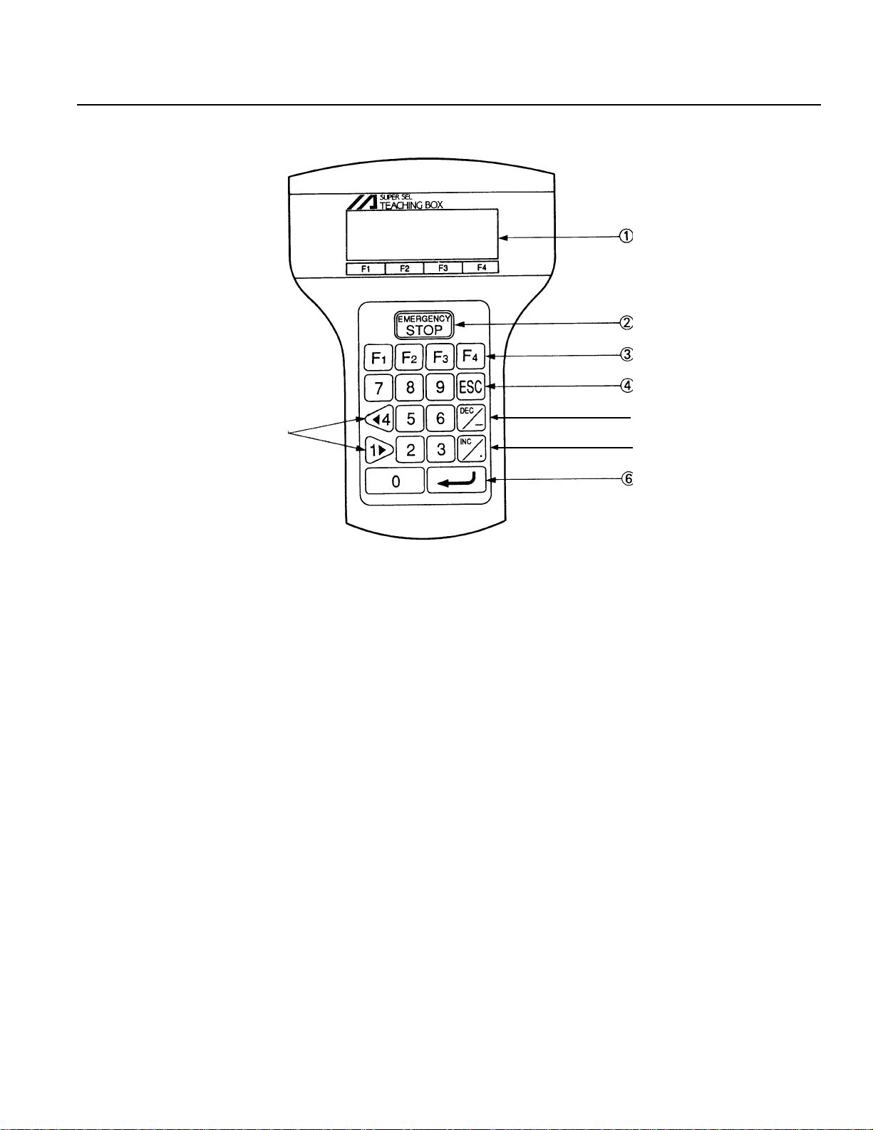
➀ LCD Display
4 lines with a 20 character per line capacity display. Shows program and motion status.
➁ EMERGENCY STOP
Whenthe emergency stop button is pressed, servos will disengage and all programmable outputs will
be turned OFF. To release the emergency stop, press Restart (F1) on the LCD Display. When an emergency stop is
pressed from a peripheral device while using the teaching pendant, you must also press the emergency stop from the
teaching pendant. Otherwise, normal operation can not be executed (See Page 77 for reference).
➂ F1, F2, F3, F4 (Multi-function Key)
Multi-function keys that correspond with the LCD Display.
➃ ESC (Escape)
The Escape Key allows the operator to go backwards in one-step increments to previous displays
to make corrections or to switch to different modes.
➄
➅
➆
➄ DEC / - (Decrement / Minus Key)
Dual function keys for use in data input and axis Jog functions.
➅ Inc / . (Increment / Point Number Key)
This key increases the Step Number or Point Number.
➆
↵ ↵
↵ (Return Key)
↵ ↵
Return Key is used to change operations and to move the cursor position.
▲
➇ 1 , 4 (Data Key, Jog Key)
Dual function key for use in data input and axis Jog functions.
▲
Page 7
Page 10
5. T eaching Pendant Function and Specification
5.2 Specification
metImetI
metImetI noitpircseDnoitpircseD
metI
ytidimuH&erutarepmeTtneibmA sselroHR%58:ytidimuHC°04~0:erutarepmeT
tnemnorivnEgnitarepOtsudevissecxeon,sagevisorrocfoeerF
thgieWtinUG005
htgneLelbaCm2
yalpsiD4X02htiwyalpsiDDCL
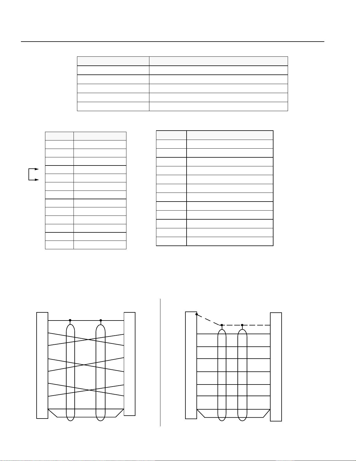
5.3 RS232C Connector (D-Sub 25 DTE Special*) For the E • G Type
.oNniP.oNniP
.oNniP.oNniP emaNlangiSemaNlangiS
.oNniP.oNniP
.oNniP.oNniP emaNlangiSemaNlangiS
.oNniP
1GF
2DXT
3DXR
4)STR(
5)STC(
6RSD
7GS
8CN
9CN
01CN
11CN
21CN
31CN
emaNlangiSemaNlangiS
emaNlangiS
*
*
*
* Pin numbers 18, 23, and 25 are for use with the teaching pendant signal.
Do not connect these pins.
.oNniP
41CN
51CN
61CN
71CN
81tuptuOV2.6+
91CN
02RTD
12CN
22CN
32WSpotSycnegremEWS.GME
42CN
52)2.6+(VO
noitpircseDnoitpircseD
noitpircseD
emaNlangiSemaNlangiS
emaNlangiS
■ RS232C Cable
Please use RS232 cable pin configuration (between controller and computer serial port).
SPMC-8DG
NEC PC
(25 Pin )
Drain
Shield
FG
1
Yellow
TXD
2
Orange
RXD
3
Gray
RTS
4
Red
CTS
5
Brown
DSR
6
Green
DTR
20
Blue
GND 7
Warning Please only use cables as specified in the charts above. Connection using other types of cables may cause breakdown in the PC interface area.
Black
Drain
Shield
Orange
Yellow
Red
Gray
Green
Blue
Black
Controller
(25 P)
1
2
3
4
5
6
20
7
FG
TXD
RXD
RTS
CTS
DSR
DTR
GND
IBM PC
(9S)
RXD
TXD
CTS
RTS
DTR
DSR
GND
(The Shield line is connected to the shell clamp area)
Page 8
2
3
8
7
4
6
5
SPMC-8DG
Shield
Orange
Yellow
Red
Gray
Green
Brown
Blue
Black
Controller
(25 P)
Orange
Yellow
Red
Gray
Green
Brown
Blue
Black
1
2
3
4
5
6
20
7
FG
TXD
RXD
RTS
CTS
DSR
DTR
GND
Page 11
5. T eaching Pendant Function and Specification
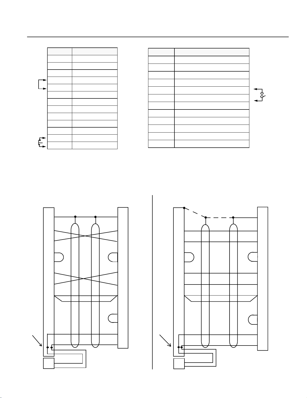
5.4 RS232C Connector (D-Sub 25 DTE Special*) for the DS Type
.oNniP.oNniP
.oNniP.oNniP emaNlangiSemaNlangiS
.oNniP
1GF
2DXT
3DXR
4)STR(
5)STC(
6RSD
7GS
8CN
9CN
01CN
11CN
212SGME
*
)
311SGME
*
• Pin numbers 12, 13, 18, 19, 23, 25 are for use with the teaching pendant signal. Do not connect these pins for RS232C.
• Pin numbers 4 and 5 are short-circuited.
• Pin numbers 12 and 13 are connected for emergency stop (B contact).
• Pin numbers 18 and 19 are ENABLE SW connecting terminal.
emaNlangiSemaNlangiS
emaNlangiS
.oNniP.oNniP
.oNniP.oNniP emaNlangiSemaNlangiS
.oNniP
41CN
51CN
61CN
71CN
81tuptuOV2.6+
*
*
91ELBANE
02RTD
12CN
22CN
32WSpotSycnegremEWS.GME
*
42CN
52)2.6+(VO
*
emaNlangiSemaNlangiS
emaNlangiS
FG
TXD
RXD
RTS
CTS
DSR
DTR
GND
Soldering
within
the shell
■ RS232C Cable
Please use RS232 cable pin configuration (between controller and computer serial port).
PC Side
(25 Pin)
1
2
3
4
5
6
20
7
SPMC-8DG
Shield
Yellow
Orange
Brown
Green
Blue Blue
Black
Red
Gray
Black
White
Drain
Orange
ShieldDrain
Orange
Yellow
Green
Brown
Black
Red
Gray
Controller Side
(25 Pin)
1
FG
2
TXD
3
RXD
4
RTS
5
CTS
6
DSR
20
DTR
7
GND
19
ENABLE
18
6V
13
EMG S1
12
EMG S2
RXD
TXD
CTS
RTS
DTR
DSR
GND
Soldering
within
the shell
PC Side
(9S)
2
3
8
7
4
6
5
SPMC-8DG
Orange Orange
Yellow
Green
Brown
Blue
Black
Red
Gray
Black
Controller Side
(25 Pin)
Shield
Yellow
Green
Brown
Blue
Black
Red
Gray
1
2
3
4
5
6
20
7
19
18
13
12
FG
TXD
RXD
RTS
CTS
DSR
DTR
GND
ENABLE
6V
EMG S1
EMG S2
EMG S1
EMG S2
EMG SW Side
Warning Please only use cables as specified in the charts above. Connection using other types of cables may cause breakdown in the PC interface area.
White
1
2
Black
EMG S1
EMG S2
EMG SW Side
White
1
Black
2
(The shield line is connected to the
shell clamp area)
Page 9
Page 12

6. Main Function Keys Above the LCD Display
rebmuNrebmuN
rebmuNrebmuN yeKyeK
rebmuN
1ccAnoitareleccAnoitareleccA
2llAllAllA
3dnAdnA)tcudorplacigoL(dnA
4grpAmargorPnoitacilppAneercstidemargorP
5sixAsixAneercsedomretemarapsixA
6+sixAsulPsixA.oNsixamorf1ddA
7-sixAsuniMsixA.oNsixamorf1tcartbuS
8SBecapSkcaBsdrawkcabrosrucehtevomdnatupniraelC
9naClecnaClecnaC
01riCelcriCneercsedomretamarapcrametsyS
11rlCraelCraelC
21?KORLC?yakOraelC?atadehtraelcotyakotisI
31ypoCypoCypoC
yeKyeK emaNdnammoCemaNdnammoC
yeK
emaNdnammoCemaNdnammoC tnetnocdnammoCtnetnocdnammoC
emaNdnammoC
tnetnocdnammoCtnetnocdnammoC
tnetnocdnammoC
*Alphabetical order
41ceDtnemerceD.oNmorf1tcartbuS
51leDeteleDeteleD
61tidEtidEneercsedomtidE
71ctEctEnoitcelesunemrehtO
81galFgalFnoitcelesyalpsidnoitairavgalF
91oGoGnoitucexeetangiseD
02emoHemoH
12TLHtlaHpotS
22cnItnemercnI.oNddA
32snItresnItresnI
42goJgoJneercsedomgoJ
52leVJyticoleVgoJneercsyticolevgoJ
62niaMniaMnoisrevMORniamedisrellortnoC
72idMtupnIataDlaunaMtupnitceridatadnoitisoP
82rtoMrotoMneercsedomretemaraprotomsixA
92emaNemaNneercsretemarapemansixA
sixaelbacilppa/edomretemarapnigirosixA
neercsedomtessixaelbacilppa-noN
03+emaNsulPemaN1(emansixAot1ddA →9, A→ )Z
13-emaNsuniMemaNZ(emansixAmorf1tcartbuS →A, 9→ )1
23toNtoN)yneD(toN
Page 10
Page 13

6. Main Function Keys Above the LCD Display
rebmuNrebmuN
rebmuNrebmuN yeKyeK
rebmuN
33rOrO)noitareporO(rO
43araPretemaraPraelcretemarapmetsyS
53mraPretemaraPedomretemaraP
63yalPyalPedomnoitucexE
73soPnoitisoPraelcaeraatadnoitisop,edomretemaraptnioP
83isoPnoitisoPneercstideatadnoitisoP
93gorPmargorPraelcaeramargorp,neercsedommargorP
04LCmaRraelCmaRneercsedomraelcyromeM
14nuRnuRdetucexegniebmargorP
24tfihStfihSedoM
34wohSwohSrotinometangiseD
44oiSC232SRO/IlaireSneercsedomretemaraPO/IlaireS
54tatSsutatSnoitidnocnoitucexemargorpetangiseD
64petSpetSpetsatadnoitisoP
74potSpotSpotS
841ptS1potSrosrucehtybdetacidnimargorpehtpotS
94LAptSllApotSsmargorpgnitucexellapotS
05ovrSovreSneercsretemarapovreS
15fovSffOovreStnadnepgnihcaettcerid•launaM
25sySmetsySneercsedomretmarapmetsyS
35caeT
45tseTtseTedomtseT
55leVyticoleVyticoleVgnittesnoitarelecca•
65reVnoisreVneeercsyalpsidnoisrevtnerruC
75trWetirWnietirW
851/01ro01ro0otyalpsidehtegnahC
yeKyeK emaNdnammoCemaNdnammoC
yeK
emaNdnammoCemaNdnammoC tnetnocdnammoCtnetnocdnammoC
emaNdnammoC
,gnihcaeTataDnoitisoP
tnadnePgnihcaeT
tnetnocdnammoCtnetnocdnammoC
tnetnocdnammoC
yalpsidnoisrevtnadnepgnihcaet,gnihcaeT
Note: Depending on the operation, there are other function keys not listed in the chart above.
Page 11
Page 14

7. Programming
SEL Language Structure
The SEL programming consists of a position and application program (command) section.
7.1 Position Program
In the position section, we have coordinates, velocity and acceleration.
*1, 2
1~1500 mm/sec
1
2
3
4
* 1 Varies according to the actuator model.
* 2 When velocity and acceleration are set in the position data, this has priority over the data set in the
*2
Standard
0.3G
noitisoP
.oN
yticoleVnoitareleccA1sixA2sixA3sixA4sixA5sixA6sixA7sixA8sixA
±9999.999mm
7991
8991
9991
0002
application program. To validate the application data, set x.xxx or 0 in the position data.
Note: The DS type is a single axis only. Also position numbers go up to 500.
Page 12
Page 15
7. Programming
7.2 Commands
The outstanding feature of the SEL language is the simplicity of its command structure which eliminates the need for a
compiler and allows high speed operation with just an interpreter.
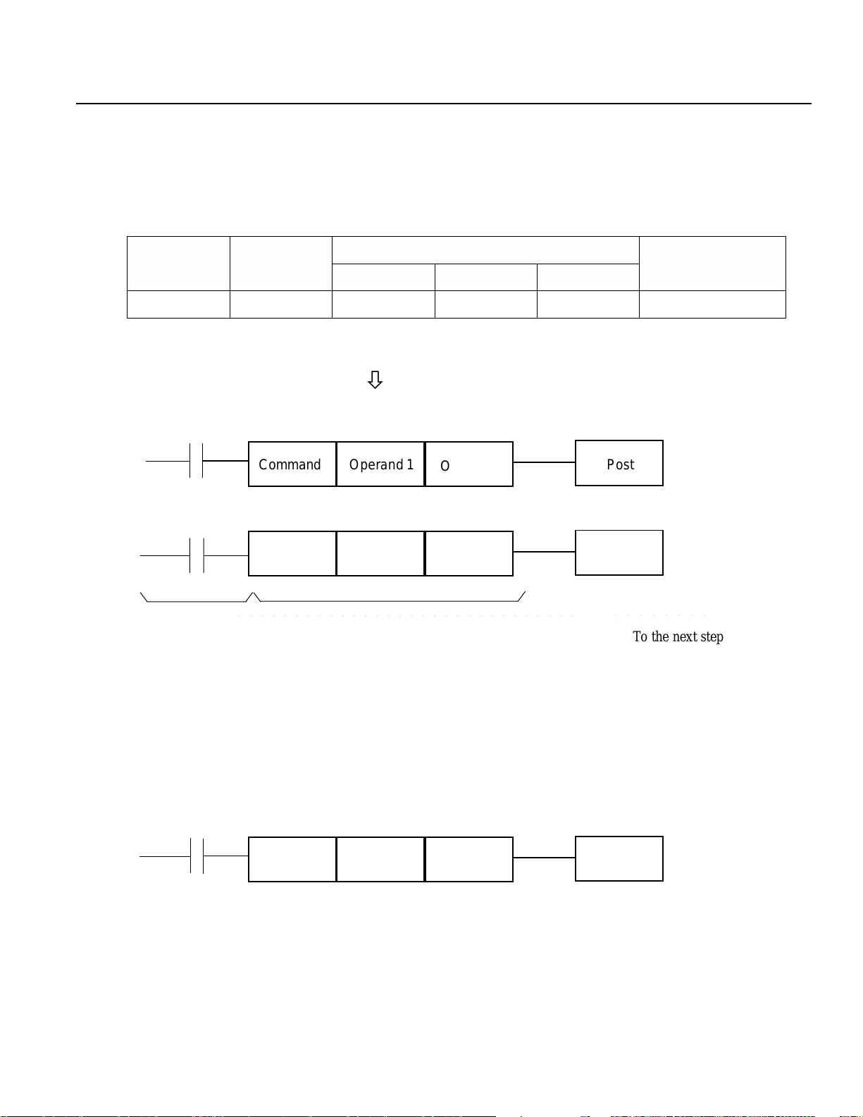
7. 2- 1 SEL Language Structure
One step of the command has the following structure.
Putting this in a ladder
diagram,
(1) The conditions before the commands are equivalent to "if ~ then" statements in BASIC language.
IF ~ THEN ELSE
noisnapxE
)RO·DNA(
noitidnoCtupnI
)galF·O/I(
dnammoC 1dnarepO 2dnarepO
ò
Command PostOperand 1
Command
○○○○○○○○○○○○○○○○○○○○○○○○○○○○○○
Operand 1
Operand 2
Operand 2
dnammoC
tsoP
)galF·troptuptuO(
Post
○○○○○○○○
To the next step
ò
Carry out a command when an input condition is established, and turn the output port ON, if output is
designated. When not established, go on to the next step regardless of the next command (ex. WTON,
WTOF). The designated output port remains the same , however it needs to be monitored carefully.
If there is no conditioning set up, carry out command unconditionally.
If condition is used as "negative condition", then place an "N" (NOT).
Input/output port & flag can be used for condition.
(2 ) Output is set based on the result of the command execution.
Operand 1
Operand 2Command Post
Actuators motion control commands: becomes OFF immediately after the command starts to be executed,
and becomes ON when the command is completed.
Computation commands: when the result becomes a certain value, it turns ON, and it stays OFF otherwise.
Output port and flag can be used for output section.
Page 13
Page 16
7. Programming
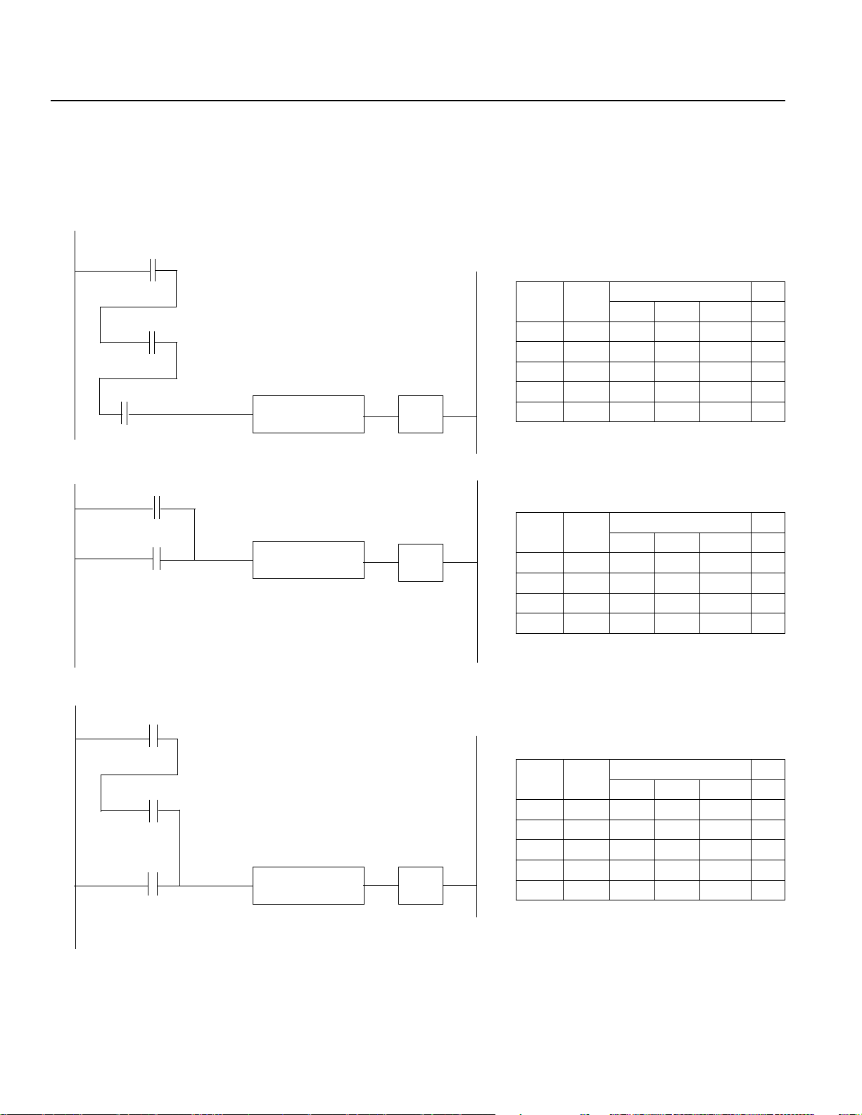
7.2-2 Expansion Condition
It is possible to combine conditions to make more complicated conditions as follows:
AND Expansion (Ladder Diagram display) (SEL Language)
Cond 1
Cond 2
Cond 3
OR Expansion
Cond 1
Cond 2
AND
AND
OR
noitanalpxEtupnI
DNA2noitidnoC
DNA3noitidnoCdnammoC1dnarepO2dnarepO
noitanalpxEtupnI
RO2noitidnoCdnammoC1dnarepO2dnarepO
dnammoC1dnarepO2dnarepO
1noitidnoC
dnammoC1dnarepO2dnarepO
1noitidnoC
sdnammoCtuptuO
sdnammoCtuptuO
AND/OR Expansion
Cond 1
Cond 2
Cond 3
AND
OR
noitanalpxEtupnI
DNA2noitidnoC
RO3noitidnoCdnammoC1dnarepO2dnarepO
dnammoC1dnarepO2dnarepO
1noitidnoC
sdnammoCtuptuO
Note: By convention, all “AND” operations are performed before the “OR” operations when they are used in
conjunction.
Page 14
Page 17
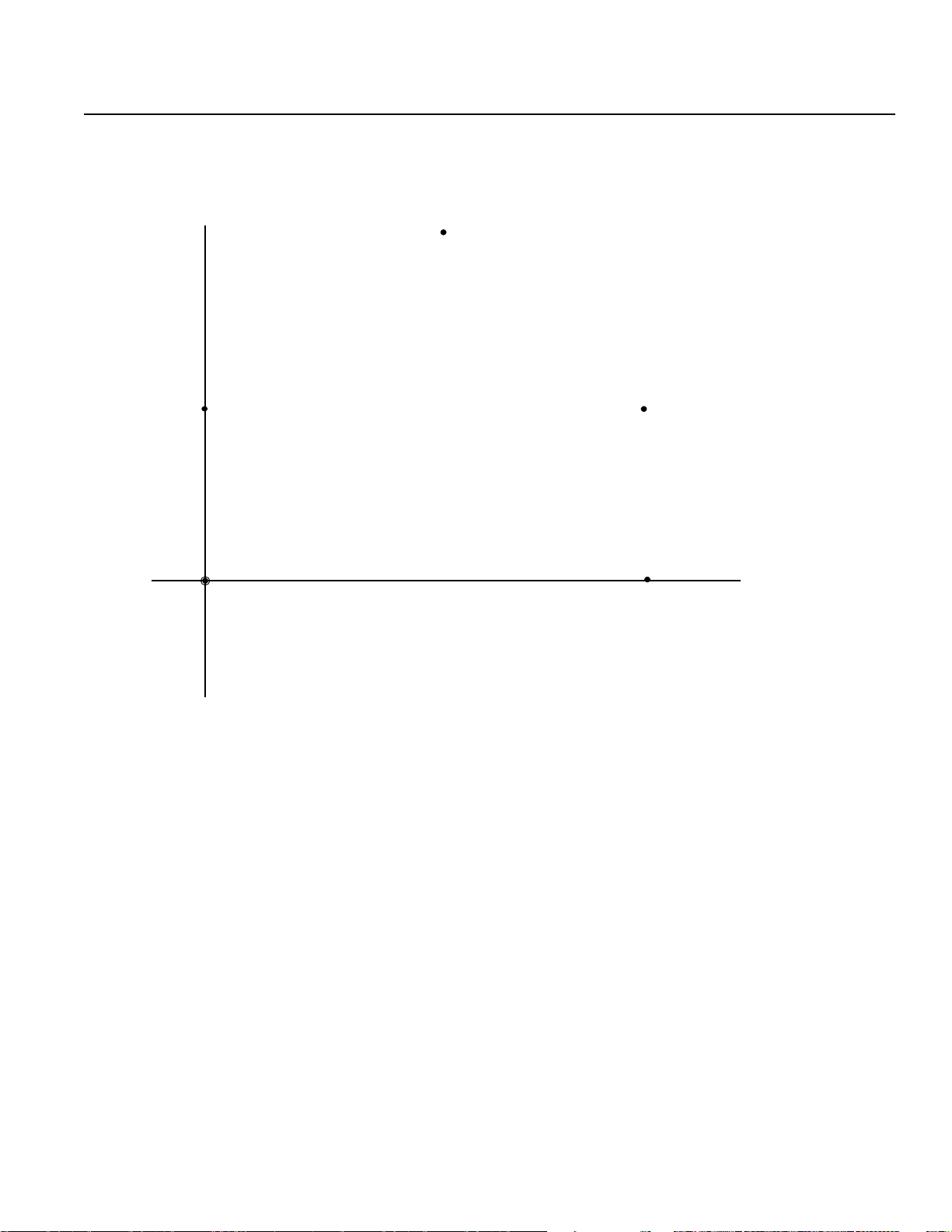
8. Examples of Simple Operation Procedure
In this chapter, we will design a program which draws a 5 sided shape. It will pass through 6 points
(➀ and ➅ share the same position), taught by a 2-axes (X,Y) actuator.
Y
100
50
➀ /
➅
➁
➂
➄
0
Origin
Position data
50
➅➀ ~
➃
100
X
* Please finish reading the rest of the operational procedure before moving ➀~ ➅.
Page 15
Page 18

8. Examples of Simple Operation Procedure
8.1 Creating a Position Data
First, we will input data for 6 points to draw a 5 sided shape, similar to the position data list shown below:
Position Data • list*
No. Acc Vel Axis (1) Axis (2)
1 x.xx xxxx 0 50
2 x.xx xxxx 50 100
3 x.xx xxxx 100 50
4 x.xx xxxx 100 0
5 x.xx xxxx 0 0
6 x.xx xxxx 0 50
SEL Teaching
Teach V2.00 09/01/97
Start (Blinking)
F1 F2 F3 F4
SEL Teaching
T each V2.00 09/01/97
Main V2.50 07/14/95
Start (Blinking)
*This is a printout of the controller
position data which we will
create in this section.
LCD Display:
Once the characters appears on the LCD display, you may
advance to the next step by pressing the appropriate function
Key located on the lower part of the screen.
First, press the F1 Key (Start).
Controller ROM Version Display:
Press the F1 Key (Start).
F1 F2 F3 F4
Mode Selection Display:
Mode Select
This is the basic screen for all operation.
Prog Play Parm Test
F1 F2 F3 F4
*Note* In case of a selection or input error, press the ESC key to return to the previous screen and then resume operation.
For any operation, if you continue pressing the ESC Key, you will eventually return to the above basic screen.
Press F1 Key (Prog).
Page 16
Page 19

8. Examples of Simple Operation Procedure
Program Mode Screen:
Prog
Press the F1 Key (Posi).
Posi Aprg
F1 F2 F3 F4
Posi
Mdi Teac Step Etc
F1 F2 F3 F4
Position data Axis 1
Mdi - 1 No 1 [1] - 2
XXXXX.XXX XXXXX.XXX
Inc Dec Clr Del
F1 F2 F3 F4
Screen explanation:
Mdi - 1 No 1 [1] - 2
Position # Axis Name
Axis # No. of axes connected
Position (Position Data) Edit Screen:
Press the F1 Key (Mdi - manual data input).
Axis 2
Position Number Input Mode:
The cursor is on the position number location.
XXXXX.XXX will display if there is no data.
Press the Return Key and match the cursor to
the position data for Axis 1.
Note 1: For existing data, keep pressing the F1
Key until reaching the screen which displays
the XXXXX.XX. Then, execute data input, or
do a substitution so that the previous data will
dissappear.
Page 17
Note 2: This screen can only display up to a maximum
of four axes. When the number of axes are
over five, please refer to Page 50 for
reference.
Page 20
8. Examples of Simple Operation Procedure
Q Data input for point 1
Mdi - 1 No 1 [1] - 2
XXXXX.XX
X XXXXX.XXX
Wrt Can Clr Etc
F1 F2 F3 F4
* It is possible to input position data up to for integer 4 digits before the decimal point and 3 digits after. The range depends on
the type of the machine. Therefore, please verify the range according to the appropriate product catalog.
Input the number 0 and press the Return Key.
0.000 will display, and the axis number and name
will change to 2. Then, the cursor position will move
to the position data for the axis 2.
Mdi - 1 No 2 [2] - 2
0.000 XXXXX.XX
Wrt Can Clr Etc
F1 F2 F3 F4
Mdi - 1 No 2 [1] - 2
0.00
0 50.000
Wrt Can Clr Etc
F1 F2 F3 F4
Mdi - 2 No 1 [1] - 2
XXXXX.XX
X XXXX.XXX
Input 50 into the position data for axis 2, then,
press the Return Key.
X
*Since the cursor position moves every time the
Return Key is pressed, input in sequence, first axis 1,
then, axis 2. For input error, move the cursor to that
location and do a substitution.
Using the F1 Key (Wrt) to establish, the Position No.
will advance by 1, turning into 2.
② Data input for point 2
Input 50 into the position data for axis 1, then press the
Return Key.
Wrt Can Clr Etc
F1 F2 F3 F4
Page 18
Page 21

8. Examples of Simple Operation Procedure
Mdi - 2 No 2 [2] - 2
50.000 XXXXX.XX
Wrt Can Clr Etc
F1 F2 F3 F4
Mdi - 2 No 1 [1] - 2
50.00
0 100. 000
Wrt Can Clr Etc
F1 F2 F3 F4
Mdi - 3 No 2 [2] - 2
XXXXX.XX
X XXXXX.XXX
Wrt Can Clr Etc
Since the cursor position moves to the position
data for the axis 2, input 100 and press the Return Key.
X
Using the F1 Key (Wrt) to establish, then, advance the
Position No. to 3.
③ Data input for point 3
Input 100 into the position data for axis 1, then press
the Return Key.
F1 F2 F3 F4
Mdi - 3 No 1 [1] - 2
100.00
0 XXXXX.XXX
Wrt Can Clr Etc
F1 F2 F3 F4
Mdi - 3 No 1 [1] - 2
100.00
0 50.000
Wrt Can Clr Etc
F1 F2 F3 F4
Input 50 into position data for axis 2, then press the
Return Key.
Press the F1 Key (Wrt), then, advance Position No.
to 4.
Page 19
Page 22

8. Examples of Simple Operation Procedure
Mdi - 4 No 1 [1] - 2
XXXXX.XX
X XXXXX.XXX
Wrt Can Clr Etc
F1 F2 F3 F4
Mdi - 4 No 2 [2] - 2
100.000 XXXXX.XX
Wrt Can Clr Etc
F1 F2 F3 F4
Mdi - 4 No 1 [1] - 2
100.00
0 0.000
④ Data input for point 4
Input 100 into the position data for axis 1, then press the
Return Key.
Input 0 into the position data for the axis 2, then
press the Return Key.
X
Press the F1Key (Wrt), and advance the Position No. to 5.
Wrt Can Clr Etc
F1 F2 F3 F4
Mdi - 5 No 1 [2] - 2
XXXXX.XXX XXXXX.XXX
Wrt Can Clr Etc
F1 F2 F3 F4
Mdi - 5 No 2 [2] - 2
0. 000 XXXXX.XX
X
Wrt Can lir Etc
F1 F2 F3 F4
⑤ Data input for point 5.
Input 0 into the position data for axis 1, then push the Return
Key.
Input 0 into the position data for axis 2, then press the
Return Key.
Page 20
Page 23

8. Examples of Simple Operation Procedure
Mdi - 5 No 1 [1] - 2
0.00
0 0.000
Wrt Can Clr Etc
F1 F2 F3 F4
Mdi - 6 No 1 [1] - 2
XXXXX.XX
X XXXXX.XXX
Wrt Can Clr Etc
F1 F2 F3 F4
Mdi - 6 No 2 [2] - 2
0.000 XXXXX.XX
Press the F1 Key (Wrt), and advance the Position No. to 6.
➅Data input for point 6
Input 0 into the position data for axis 2, and then
press the Return Key.
Input 50 into the position data for axis 2, and then press the
Return Key.
X
Wrt Can Clr Etc
F1 F2 F3 F4
Mdi - 6 No 1 [1] - 2
0.00
0 50.000
Wrt Can Clr Etc
F1 F2 F3 F4
Mdi - 7 No 1 [1] - 2
XXXXX.XX
X XXXXX.XXX
Wrt Can Clr Etc
F1 F2 F3 F4
Press the F1Key (Wrt) to establish, and then the Position No.
screen will turn into 7.
Page 21
Page 24

8. Examples of Simple Operation Procedure
Push the ESC key to return to the Position Edit Screen.
Mdi - 7 No 1 [1] - 2
XXXXX.XXX XXXXX.XXX
Wrt Can Clr Etc
F1 F2 F3 F4
Push the ESC key again to dsiplay the Program Mode Screen.
Posi
Mdi Teac Step Etc
F1 F2 F3 F4
Prog
Posi Aprg
F1 F2 F3 F4
Mode Select
Prog Play Parm T est
F1 F2 F3 F4
Push the ESC key again to return to the Mode Selection
Screen.
* Pressing the ESC key further will not change the screen.
This concludes the basic position data input.
Page 22
Page 25
8. Examples of Simple Operation Procedure
8.2 Creating an application program
8.2-1 In this section, we will create an application program which will move the position data location that was
created in the previous section.
Application program • list *
Line A/O N (1) OP-CODE OPERAND1 OPERAND2 POST COMMENT
1 HOME 11
2 V EL 100
3 MOVL 1
4 MOVL 2
5 MOVL 3
6 MOVL 4
7 MOVL 5
8 MOVL 6
9 EXIT
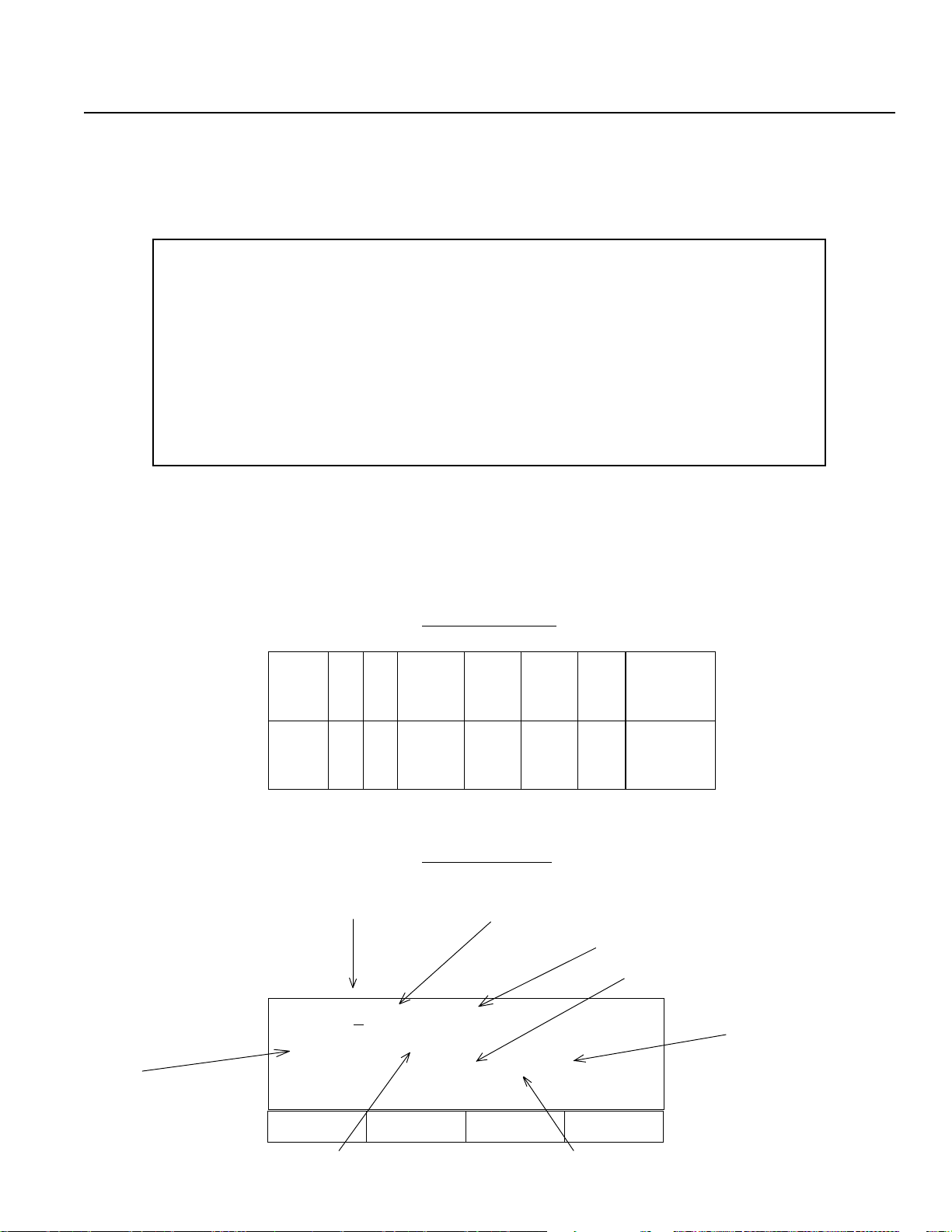
* This is a printout of the application program which we will create (input) in this section.
The order of the application program input in the teaching pendant differs from the application program coding sheet (see
diagram below). The order in the teaching pendant is as follows: command (OP-CODE), operand 1, 2 (OPRND 1, 2), output
requirement (POST), expansion requirement (A/O) and continuous requirement (N).
OP-CODE
[Example]
[Example]
In the coding sheet:
petSpetS
petSpetSO/AO/A
petS
11111DNADNA
O/AO/ANNNNNEDOC-POEDOC-PO
O/A
DNADNA02N02N
02N02NEMOHEMOH
DNA
02N
EDOC-POEDOC-PO1DNRPO1DNRPO
EDOC-PO
EMOHEMOH1111111111009009
EMOH
➨
In the LCD screen:
Program No.
Edit 1 - 1 [ 50]
HOME 11
STEP No.
900 A N 20
1DNRPO1DNRPO2DNRPO2DNRPO
1DNRPO
2DNRPO2DNRPOTSOPTSOP
2DNRPO
TSOPTSOPTNEMMOCTNEMMOC
TSOP
009009
009
Step number
POST
TNEMMOCTNEMMOC
TNEMMOC
N
Inc Dec Clr Del
F1 F2 F3 F4
OPRND1 A/O
Page 23
Page 26

8. Examples of Simple Operation Procedure
Mode Select
Prog Play Parm T est
F1 F2 F3 F4
Prog
Posi Aprg
F1 F2 F3 F4
Aprg
Select the F1 Key (PROG) from the Mode Selection Screen.
Select the F2 Key (Aprg) from the Program Mode Screen.
Select the F1 Key (Edit) from the Application Program Edit
Screen.
Edit Copy
F1 F2 F3 F4
Edit 1- 1 [ 0]
ABPG ACC ADD AND
F1 F2 F3 F4
Edit
1- 1 [ 0]
ABPG ACC ADD AND
F1 F2 F3 F4
After the screen changes to program No. Input Mode Screen,
move the cursor location using the Return Key. Then, press
the Return Key twice.
*For existing program data input, substitution will clear the
previous data.
Edit command input mode:
Retrieve the HOME command (Homing). Pressing the DEC /
- Key will place the alphabet of the command in a
descending order. Pressing the INC /. Key will place the
alphabet of the command in an ascending order.
Page 24
Page 27
8. Examples of Simple Operation Procedure
Retrieval is performed either by the DEC / - Key or INC
Edit 1 - 1 [ 0]
_
HOME IN INB JBWF
F1 F2 F3 F4
/. Key. Continue pressing either of the Keys until the target
command displays. Since HOME is displayed in the display
window, in this example, select the F1 (HOME) Key. HOME
is displayed on the command input location.
[Note: In some cases, the displayed function key location
(F1 ~F4) of Home will differ.
Edit 1 - 1 [ 0]
Home
HOME IN INB JBWF
F1 F2 F3 F4
Edit 1 - 1 [ 0]
Home 11_
* BS Clr
F1 F2 F3 F4
Since the cursor moves to the operand 1 input position when
pressing the Return Key, input 11 so that both X and Y axes
homes at the same time. Why 11?
0 • • Not used
?1 1
1 • • Used.
Therefore, homing will be executed
Y-Axis
Press the Return Key.
X-Axis
to both axes in this example
(See Page 65 for Homing reference*1).
Edit 1 - 1 [ 0]
Home 11
_
BS Clr
F1 F2 F3 F4
Edit 1- 1 [ 0]
Home 11
And Or Clr Not
F1 F2 F3 F4
Press the Return Key.
Press the Return Key.
Page 25
Page 28

8. Examples of Simple Operation Procedure
Select the F4 Key (Wrt), and advance to Step No.2.
Edit 1- 1 [ 0]
HOME 11
Clr Wrt
F1 F2 F3 F4
Edit 1- 2 [ 1]
_
HOME IN INB JBWF
F1 F2 F3 F4
Edit 1- 2 [ 1]
_
TIMW VEL WTOF WTON
F1 F2 F3 F4
Edit 1- 2 [ 1]
VEL
Continuously press either the DEC / - Key or INC / . Key,
and retrieve VEL.
In this example, select the F2 Key (VEL).
[Note: In some cases, the displayed function key location
(F1~F4) of VEL may differ.]
Press the Return Key.
TIMW VEL WTOF WTON
F1 F2 F3 F4
Edit 1- 2 [ 1]
VEL _
* BS Clr
F1 F2 F3 F4
Here, we will input velocity as 100, then, press the Return
Key.
[Note: To verify maximum velocity, please refer to the
appropriate product catalog.]
Page 26
Page 29

8. Examples of Simple Operation Procedure
Press the Return Key.
Edit 1- 2 [ 1]
VEL 100
And Or Clr Not
F1 F2 F3 F4
Edit 1- 2 [ 1]
VEL 100
Clr Not
F1 F2 F3 F4
Edit 1- 3 [ 2]
_
TIMW VEL WTOF WTON
F1 F2 F3 F4
Edit 1 - 3 [ 2]
_
MOD MOVL MOVP MULT
Press the F4 Key, and advance to Step No.3.
Continuously press the DEC / - Key until MOVL is
displayed.
In this example, select the F2 Key (MOVL).
[Note: In some cases, the displayed function key location
(F1~F4) of MOVL may differ.]
F1 F2 F3 F4
? The difference between MOVL and MOVP:
MOVP moves the actuator to the designated position number from point to point without interpolation.
MOVL moves the actuator to the designated point while using interpolation (not point to point).
Edit 1 - 3 [ 2]
MOVL
MOD MOVL MOVP MULT
F1 F2 F3 F4
Press the Return Key. Then, input 1 for Position No. into
operand 1.
Page 27
Page 30

8. Examples of Simple Operation Procedure
Press the Return Key 3 times.
Edit 1- 3 [ 2]
MOVL 1_
* BS Clr
F1 F2 F3 F4
Select the F4 Key (Wrt). The screen will advanced to Step
Edit 1- 3 [ 2]
MOVL 1
Clr Wrt
F1 F2 F3 F4
No. 4.
Edit 1- 4 [ 3]
_
MOD MOVL MOVP MULT
F1 F2 F3 F4
Edit 1- 4 [ 1]
MOVL 2_
* BS Clr
F1 F2 F3 F4
Edit 1- 5 [ 4]
_
MOD MOVL MOVP MULT
In this example, select the F2 Key (MOVL), and then press
the Return Key. Input 2 for Position No. into operand 1.
[Note: In some cases, the displayed function key location
(F1 ~F4) of MOVL may differ.]
Press the Return Key 3 times, and select the F4 Key (Wrt).
The screen will advance to Step No.5.
In this example, select the F2 Key (MOVL), and then press
the Return Key. Input 3 for position No. into operand 1.
[Note: In some cases, the displayed function key location
(F1 ~F4) of MOVL may differ.]
F1 F2 F3 F4
Page 28
Page 31

8. Examples of Simple Operation Procedure
Press the Return Key 3 times, and select the F4 Key (Wrt).
Edit 1- 5 [ 4]
MOVL 3 _
* BS Clr
F1 F2 F3 F4
Edit 1- 6 [ 5]
_
MOD MOVL MOVP MULT
F1 F2 F3 F4
The screen will advance to Step No. 6.
In this example, select the F2 Key (MOVL), and select the
Return Key. Input 4 for position No. into operand 1.
[Note: In some cases, the displayed function key location
(F1 ~F4) of the MOVL may differ.]
Edit 1- 6 [ 5]
MOVL 4_
* BS Clr
F1 F2 F3 F4
Edit 1- 7 [ 6]
MOVL 5_
* BS Clr
F1 F2 F3 F4
Press the Return Key 3 times, and select the F4 Key (Wrt).
The screen will advance to Step No. 7. In this example,
select the F2 Key (MOVL), and press the Return Key.
Input 5 for position No. into operand 1.
[Note: In some cases, the displayed function key location
(F1 ~F4) of MOVL may differ.]
Press the Return Key 3 times, and select the F4 Key (Wrt).
The screen will advance to Step No. 8. In this example,
select the F2 Key (MOVL), and press the Return Key.
Input 6 for position No. into operand 1.
[Note: In some cases, the displayed function key location
(F1 ~F4) of MOVL may differ.]
Page 29
Page 32

8. Examples of Simple Operation Procedure
Press the Return Key 3 times, and select the F4 Key (Wrt).
Edit 1- 8 [ 7]
MOVL 6_
The screen will advance to Step No. 9. Continuously press the
DEC/ - Key until EXIT displays. In this example, select the
F3 Key (EXIT) and then, press the Return Key.
* BS Clr
F1 F2 F3 F4
?
EXIT ends a program. In order to stop without inputing EXIT above a program, please refer to Page 39, section
9.2-2, entitled, “How to stop operation during or methods other than EXIT.”
Edit 1- 9 [ 8]
EXIT
EDSR EOR EXIT EXPG
F1 F2 F3 F4
[Note: In some cases, the displayed function key location
(F1
~F4) of the EXIT may differ.]
Press the Return Key twice, and establish with the F4 Key
(Wrt).
Edit 1- 10 [ 9]
EXIT
EDSR EOR EXIT EXPG
F1 F2 F3 F4
Mode Select
Prog Play Parm Test
F1 F2 F3 F4
* For this example, programming ends. To continue
inputting another program, refer to Page 31.
After pressing the ESC Key several times, return the screen
to the Mode Selection Screen.
Page 30
Page 33

8. Examples of Simple Operation Procedure
8. 2-2 How to input another program as a continuation
[Continuation from P.30]
Edit 1-10 [ 9]
_
EDSR EOR EXIT EXPG
F1 F2 F3 F4
Edit 1-1
0 [ 9]
In c Dec Clr Etc
F1 F2 F3 F4
Press the ESC Key to execute Step No. Input Mode.
(To verify each step, either do a direct number input into
Step No. during this screen. Or use the F1 Key (Inc) and
F2 Key (DEC) to observe the Step No. you wish to verify.
By pressing the ESC Key once more will change the
screen into Program No. Input Mode Screen. Therefore,
either do a direct number, or by pressing the F1 Key (Inc),
the Program No.will turn into 2, allowing you to create
another program.
Edit 2-1 [ 0]
The Mode Selection Screen will return by continuously
pressing the ESC key.
Inc Dec Clr Etc
F1 F2 F3 F4
Mode Select
Prog Play Parm Test
F1 F2 F3 F4
* To turn Mode Selection Screen into Program No. Input Mode Screen, please refer to Page 23 and on. Use the program No.
Input Mode Screen to verify that the cursor is at the Program No. location. Then, either press the F1 Key or do an direct
number input. Make sure that other programs can be input into the screen so that new programs can be created.
Page 31
Page 34

9. Operation
9.1 Program Operation
In this section, we will operate the program which was created in the previous chapter.
Select the F2 Key (Play) from the Mode Selection Screen.
Mode Select
Prog Play Parm Test
F1 F2 F3 F4
Select the F1 Key (Prog).
Play
Prog Posi
F1 F2 F3 F4
Play 1- 1 [ 9]
HOME 11
In c Dec Clr
F1 F2 F3 F4
Play
1- 1 [ 9]
HOME 11
Show Go Stat HL T
(Note: The left screen will only be displayed for the
DS type. For the Super SEL type, the screen will
shift directly to the screen below.)
After confirming that the Play Program Input Mode
Program No. is 1, press the Return Key.
* If the Program No. 1 is not the program you input, then
continue pressing the F1 Key, and match your program
with the Program No.
When F2 Key (Go) is selected, homing begins. When
homing is completed, the program will move according
to the created Position Data Program.
F1 F2 F3 F4
Page 32
Page 35

9. Operation
Play 1 [ProgStatus]
ERR_STEP [NONE] [STOP]
Posi Play Stat Etc
F1 F2 F3 F4
Play 1- 1 [ 9]
HOME 1 1
Inc Dec Clr
F1 F2 F3 F4
Mode Select
When the operation is done by EXIT, this screen will be
displayed. Press the ESC Key.
By continuously pressing the ESC Key, the screen will
display the Mode Selection Screen.
Prog Play Parm Test
F1 F2 F3 F4
Page 33
Page 36

9. Operation
9.2 Application Program Changes
9.2-1 Setting a continuous movement in a program (Ins: insert, Del: delete)
In this section, we will set a continuous movement in a program using commands TAG and GOTO.
? GOTO refers to jump. By setting TAG before jump, you can repeat and skip a program.
Mode Select
Prog Play Parm Test
F1 F2 F3 F4
Prog
Posi Aprg
F1 F2 F3 F4
Aprg
Select the F1 Key (Prog) from the Mode Selection Screen.
Select the F2 Key (Aprg) from the Program Mode Screen.
Select the F1 Key (Edit) from the Application Program Edit
Screen.
Edit Copy
F1 F2 F3 F4
Page 34
Page 37

9. Operation
Edit 1- 1 [ 9]
HOME 11
Inc Dec Clr Etc
F1 F2 F3 F4
Edit 1-
HOME 11
Inc Dec Clr Etc
F1 F2 F3 F4
1 [ 9]
Since the screen changes to the Program Edit Mode Screen,
press the Return Key once, and match the cursor location to
the Step No. location.
Input TAG between Step No. 2 of command VEL and Step No.
3 of command MOVL, by either directly inputting the number
3 or pressing the F1 Key (Inc) twice until the number 3 is
displayed.
Edit 1-
3 [ 9]
MOVL 1
Inc Dec Clr Etc
F1 F2 F3 F4
Edit 1- 3 [ 9]
MOVL 1
Ins Del Etc
F1 F2 F3 F4
Edit 1- 3 I [ 9]
_
Select the F4 (Etc) Key.
Select the F1 Key (Ins). 1 of Insert will be displayed behind
Step No.3.
Continusouly press either the DEC/- Key or the INC /.
Key. In this example, select the F2 Key (TAG), and press the
Return Key.
EDSR EOR EXIT EXPG
F1 F2 F3 F4
[Note: In some cases, the displayed function key location
(F1~F4) of TAG may differ.]
Page 35
Page 38

9. Operation
Input number 1 into operand 1.
Edit 1- 3 I [ 9]
Tag _
BS Clr
F1 F2 F3 F4
* When inputting a number into TAG operand 1, the number should be a convenient number that is under 64. However, please
select a number that correspond to the number which will enter GOTO operand 1.
Edit 1 - 3 I [ 9]
TAG 1_
BS Clr
F1 F2 F3 F4
Edit 1 - 4 I [ 10]
_
SVON TAG TAN TIMC
F1 F2 F3 F4
Edit 1 - 4 [ 10]
MOVL 1
Press the Return Key, and select the F4 Key (Wrt).
Press the ESC Key, and display the Step No. 4 Screen.
Either input the number 3 or select the F2 (Dec) Key, and
press the Return Key. Verify that Step 3 step number is
changed from 9 to 10 in the TAG Command Screen.
Inc Dec Clr Etc
F1 F2 F3 F4
Page 36
Page 39

9. Operation
Edit 1- 3 [ 10]
TAG 1
SVON TAG TAN TIMC
F1 F2 F3 F4
Edit 1-
TAG 1
Inc Dec Clr Etc
F1 F2 F3 F4
3 [ 10]
Press the ESC Key, and match the cursor to the Step No.
location.
Next, delete EXIT and insert GOTO, by either leaving the
cursor location where it is and directly inputting the number
10, or pressing the F1 Key (Inc) 7 times until the number 10
is displayed.
Edit 1 - 10_ [ 10]
Exit
Inc Dec Clr Etc
F1 F2 F3 F4
Edit 1-10 [ 9]
Ins Del Etc
F1 F2 F3 F4
Edit 1-10 [ 10]
EXIT
Select the F4 (Etc) Key.
Select the F2 (Del) Key.
Since Del is blinking, select the F2 Key (Del) once again.
Del (Blinking)
F1 F2 F3 F4
Page 37
Page 40

9. Operation
Edit 1 - 10 [ 9]
Ins Del Et c
F1 F2 F3 F4
Press the Return Key.
Edit 1 - 1
0 [ 9]
_
SVON TAG TAN TIMC
F1 F2 F3 F4
Edit 1 - 10 [ 9]
GOTO
EXSR GOTO GRP HOLD
F1 F2 F3 F4
Edit 1- 10 [ 9]
GOTO 1_
Continuosly press either the DEC/ - Key, or INC / . Key until
GOTO is displayed. In this example, select the F2 Key
(GOTO).
[Note: In some cases, the displayed function key location
(F1∼F4) of GOTO may differ.]
Press the Return Key, and input the same number which was
input in operand 1 of TAG operand 1. Here, 1 is input.
Press the Return Key twice and establish with the F4 Key
(Wrt). Return to the Mode Selection Screen, and repeat the
movement one more time (see Page 32 and on).
* BS Clr
F1 F2 F3 F4
Page 38
Page 41

9. Operation
9. 2-2 How to stop operation during or by other methods excluding EXIT
Select the STOP Key when executing a program, when the EXIT command is not input, or when
you wish to force end a program.
Edit 1- 0 [ 9]
MOVL 6
Posi Play Stat Etc-
F1 F2 F3 F4
While in execution, press the F4 Key (Etc) twice until STOP
is displayed.
Play [ Run 1- 1 ]
1-6
Stop Etc-
F1 F2 F3 F4
PlayStop [ Run 1- 1 ]
1-6
StpAL Stp1
F1 F2 F3 F4
PlayStop [ Run 0- 0 ]
Press the F1 Key (Stop). When several programs are being
operated using the multi-task, the StpAL will stop all of the
programs, while the Stp 1 will select and stop a Program No.
Here, you may select either the F3 Key or the F4 Key to
stop.
Use the ESC Key to return to the Mode Selection Screen.
Although the 01 will continue to be displayed on the
controller code display, this is not a problem.
Please press any key
F1 F2 F3 F4
* You may also use EMERGENCY STOP to force a stop (for reference, see Page 77).
(For the DS type, P01 will be displayed).
Page 39
Page 42

9. Operation
9.2 -3 Expansion Condition Input Procedure
In this section, we will learn the expansion condition input procedure using the Application Program List example
below:
Program No 2
Line A/O N (1) OP-CODE OPERAND 1 OPERAND 2 POST COOMMENT
l N22
2 AND N2 0 HOME 11 900
Mode Select
Application Program • List
Select the F1 Key from the Mode Selection Screen.
Prog Play Parm Test
F1 F2 F3 F4
Prog
Posi Aprg
F1 F2 F3 F4
Aprg
Edit Copy
Select the F2 Key (Aprg) from the Program Mode Screen.
Select the F1 Key from the Application Program Edit Screen.
F1 F2 F3 F4
Page 40
Page 43

9. Operation
Edit 1 - 1 [ 10]
HOME 11
Inc Dec Clr Del
F1 F2 F3 F4
The screen will change into the Program No. Input Mode
Screen, while the screen condition will change into the
Program No. 1 which was created in the Application
Program. Either press the F1 Key (Inc), or input the number
2 to turn the Program No. into 2.
Edit 2 - 1 [ 0]
Inc Dec Clr Del
F1 F2 F3 F4
Edit 2 -
1 [ 0]
Inc Dec Clr Del
F1 F2 F3 F4
Edit 2 - 1 [ 0]
_
EXSR GOTO GRP HOLD
Press the Return Key, and move the cursor to the Step No.
position.
Press the Return Key once again, and move the cursor to the
command input position.
Here, we will not input a command. Instead, since this is only
for a requirement input, press the Return Key once to change
the screen into the Continuous Requirement Input Mode
Screen.
F1 F2 F3 F4
Edit 2 - 1 [ 0]
And Or Clr Not
F1 F2 F3 F4
Select the F4 Key (Not).
Page 41
Page 44

9. Operation
Edit 2- 1 [ 0]
N_
And Or Clr Not
F1 F2 F3 F4
Edit 2- 1 [ 0]
N22_
And Or Clr Not
F1 F2 F3 F4
Edit 2- 2 [ 1]
_
EXSR GOTO GRP HOLD
The screen will display N of NOT (A is for AND, and O
is for OR). Here, we will input the number 22.
Press the Return Key, and establish with the F4 Key (Wrt).
Then, advance to No.2.
In this example, press the INC /. Key once and display
HOME. Then, select the F1 Key (HOME).
[Note: In some cases, the displayed function key location
(F1 ~F4) of the HOME may differ.]
F1 F2 F3 F4
Edit 2- 2 [ 1]
HOME
HOME IN INB JBWF
F1 F2 F3 F4
Edit 2- 2 [ 1]
HOME 1 1
_
BS Clr
F1 F2 F3 F4
Press the Return Key once, and input the number 11 into
operand 1. Then, once again press the Return Key.
Since the screen will display the Result Input Mode Screen,
input 900 of result output. Then, press the Return Key.
Page 42
Page 45

9. Operation
Edit 2- 2 [ 1]
HOME 11
900 _
And Or Clr Not
F1 F2 F3 F4
Edit 2- 2 [ 1]
HOME 11
900 A_
And Or Clr Not
F1 F2 F3 F4
Edit 2- 2 [ 1]
HOME 11
900 A N20_
Here, the screen will change into the Continuous Input Mode
Screen. Select the F1 Key (And).
The screen will display A of AND. Select the F4 Key (Not)
and input the number 20.
Press the Return Key.
And Or Clr Not
F1 F2 F3 F4
Edit 2- 2 [ 1]
HOME 11
900 A N20_
Clr Wrt
F1 F2 F3 F4
Edit 2- 3 [ 2]
_
HOME IN INB JBWF
Select the F4 Key (Wrt).
Use the ESC Key to return to the Program Mode Screen.
This concludes the Expansion Condition Input Procedure.
F1 F2 F3 F4
Page 43
Page 46

9. Operation
9.3 Position Operation (DS type only)
There are two methods in Position Operation: One is “Moving One Step at a Time” Method, and the second is the
“Consecutive Movement” Method.
9.3 -1 Step Operation
Mode Select
Prog Play Parm Test
F1 F2 F3 F4
Play
Prog Posi
F1 F2 F3 F4
Select the F2 Key (Play) from the Mode Selection Screen.
Selec the F2 Key (Posi).
Play
HOME
F1 F2 F3 F4
Play
Moving now to Home
F1 F2 F3 F4
Select the F1 Key (HOME) to execute homing.
This is the screen during homing.
Page 44
Page 47

9. Operation
Play - 2 No 1 [1] -1
200.000
Inc Dec
F1 F2 F3 F4
Play - 2 No 1 [1] -1
200.000
Step Cont
F1 F2 F3 F4
Press either the F1 Key (Inc) or F2 Key (Dec), and select the
first Position No. you wish to move. then, determine with the
Return Key ( ↵).
(Here, select the Position No. 2)
* F1 Key (Inc) will increase the No. while the F2 Key
(DEC) will decrease the No.
Press the F1 Key (Step), and select the Step Operation.
Play S - 2 No 1 [1] -1
200.000
Go+ Go-
F1 F2 F3 F4
When F1 Key (Go+) is selected:
Press the F1 Key (Go+) to move to Position No. 2.
When the move is completed, Position No.3 is displayed.
When the F2 Key (Go-) is selected:
Press the F2 Key (Go-) to move to Position No. 2.
When the move is completed, Position No.1 is displayed.
Page 45
Page 48

9. Operation
9.3- 2 Consecutive Operation
Mode Select
Prog Play Parm Test
F1 F2 F3 F4
Select the F2 Key (Play) from the Mode Selection Screen.
Play
Prog Posi
F1 F2 F3 F4
Play
HOME
F1 F2 F3 F4
Play
Selec the F2 Key (Posi).
Select the F1 Key (HOME) to execute homing.
This is the screen during homing.
Moving now to Home
F1 F2 F3 F4
Page 46
Page 49

9. Operation
Play - 2 No 1 [1] - 1
200.000
Inc Dec
F1 F2 F3 F4
Play - 2 No 1 [1] - 1
200.000
Step Cont
F1 F2 F3 F4
Play C- 2 No 1 [1] - 1
200.000
Press either the F1 Key (Inc) or F2 Key (Dec), and select the
first Position No. you wish to move. Then, determine with the
Return Key (↵).
(Here, select position No. 2)
* F1 Key (Inc) will increase the No. while the F2 Key
(DEC) will decrease the No.
Press the F2 Key (Cont), and select Step Operation.
When F1 Key (Go) is pressed, the moving position will
execute Consecutive Operation while displaying in sequence.
To stop, press the F2 Key (Stop).
Go Stop
F1 F2 F3 F4
Page 47
Page 50

9. Operation
9.3 -3 Consecutive Operation Sequence)
During a Consecutive Operation Movement, execute the set Position No. to the next Position No. in sequence. For an
unregistered position, return to the next position No. in front of the previous unregistered Position No. Then, execute the set
Position No. to the next Position No. in sequence.
.oNnoitisoPnoitareleccAyticoleVnoitisoP
13.0057000.05
23.0057000.002
33.0005000.051
43.0005000.002
• • • • Unregistered position
➃
↓
➄
↓
➀
↓
➁
↓
➂
• • • • Unregistered position
Set Position No.
5x.xxxxxxx.xxx
6 3.0 057 000.001
7 3.0 006 000.002
8 3.0 002 000.003
9 3.0 057 000.052
01 3.0 057 000.051
11x.xxxxxxx.xxx
21x.xxxxxxx.xxx
313.0005000.001
Page 48
Page 51

10. Explanation of Each Function Screen
Mode Selection Screen
Prog
Mode
Select
Play
Parm
Test
10.1 Prgra m Mode
Program Mode Screen
Prog
Mode
Select
10.1-1 Position Edit Screen
Play
Parm
Test
Posi
Aprg
Mode Select
Prog Play Parm Test
F1 F2 F3 F4
This the basic screen for all operation.
Use the “ESC” Key to return to this screen.
Prog
Posi Aprg
F1 F2 F3 F4
Select the F1 Key (Posi) to view the Position Edit Screen.
Mode
Select
Prog
Play
Parm
Test
Posi
Aprg
Mdi
Teac
Step
Etc
Posi
Mdi Teac Step Etc
F1 F2 F3 F4
Select the F1 Key (Mdi) to input position data number.
Page 49
Page 52

10. Explanation on Each Function Screen
Position Input Mode
Mdi
Posi
Prog
Aprg
You may numerically input a position.
Position Input Mode Screen
Teac
Step
Etc
↵
Mdi
Teac
Posi
Step
Etc
Inc
Dec
Clr
Etc
Inc
Dec
Clr
Del
Wrt
Can
Clr
Etc
Mdi - 1 No 1 [1] - 2
xxxx.xxx xxxxx.xxx
200. 000
Inc Dec Clr Del
F1 F2 F3 F4
You may move Position No.1 through 2000, or input a number
directly.
(For the DS type, you may move position No. 1 through 500.)
Please refer to Page 16, section 8.1, entitled, “Creating
Position Data” for input procedure.
The screen has the following two methods:
Axis 1
Mdi - 1 No 1 [1] - 8
100.00
0 100. 000
100.000 100. 000
Axis 3
Wrt Can Clr Etc
F1 F2 F3 F4
Axis 2
Axis 4
When the number of actuator axes is over 5 axes,
the next screen will appear.
Continuously press the Return Key 4 times
↵
Mdi - 1 No 1 [1] - 8
Axis 5
Axis 7
100.00
100.000 100. 000
Axis+ Axis- V e l Etc
Use either the Axis+ or Axis- to move the cursor until it has
reached Axis 5. Then, once again, select Etc.
Mdi - 1 No 5 [5] - 8
100.00
100.000 100. 000
Mdi Teac Step Etc
F1 F2 F3 F4
The screen will change into the position input mode for Axis
5 though Axis 8.
Page 50
0 100. 000
F1 F2 F3 F4
0 100. 000
When Etc is selected
Axis 6
Axis 8
Page 53
10. Explanation on Each Function Screen
Teaching Mode
Prog
Mdi
Posi
Aprg
There are two methods in Position
Teaching: One is the Direct Manual
Actuator Move Method, and the other is
the Teaching Using the Key Method.
Teac
Step
Etc
Inc
Dec
Clr
Del
Teac
Display (Blinking)
HOME Teac Step Etc
F1 F2 F3 F4
Upon installing power and in teaching mode, the screen will
change to the Homing Screen.
Press the F1 Key (HOME).
➨
Teac
Moving now to Home
F1 F2 F3 F4
This screen appears during homing. Unless the power is turned OFF
thereafter, this screen will be skipped, and the screen below will first
appear.
Upon homing
➨
Teac -
1 No 1 [1] - 2
0.000 50.000
Inc Dec Clr Del
F1 F2 F3 F4
➨
↵ (Return Key)
➨
Mdi - 1 No 1 [1] - 2
0.000 50.000
Jvel Jog Svof Etc
F1 F2 F3 F4
Select either the F2 Key (Jog) or the F3 Key (Svof).
Jog • • • Allows you to move a position using key during Servo ON.
Svof • • • Allows you to manually position the actuator during Servo OFF
.
Page 51
Page 54

10. Explanation on Each Function Screen
Jog Speed Set Mode
Jvel
Teac
* The maximum value varies according to
machine type. Therefore, please refer to
the appropriate product catalog.
Jog Mode
T eac
↵
↵
Jog
Svof
Etc
Jvel
Jog
Svof
Etc
Axis
Clr
Wrt
Jvel
Svof
Etc
Teac - 1 No 1 [1] - 2
0.000 50.000
Jvel [ 03
0 ] JAcc [0.30]
Axis Clr
F1 F2 F3 F4
Initial set value using a parameter
(for reference, see Page 61).
Jog - 1 No 2 [2] - 2
0.00
0 0.000
Wrt Jvel Svof Etc
F1 F2 F3 F4
Use the Key to move the actuator. The current position
data displays on the screen.
- +
Continue pressing the Key. The data will stop changing once you
release the Key.
➨
Velocity Set • Axis Change Mode
Jog - 1 No 1 [1] - 2
18.62
5 0.000
Wrt Jvel Svof Etc
F1 F2 F3 F4
To move the cursor to Axis 2, either press the Return Key or by
selecting the F4 Key, the Axis No. and Axis Name will change.
By selecting the F4 Key (Etc),
➨
Jog - 1 No 1 [1] - 2
18.625
0.00
0
Wrt Jvel Svof Etc
F1 F2 F3 F4
+
Once the cursor position moves to Axis 2, use the Key to execute
axis move.
Page 52
Page 55

10. Explanation on Each Function Screen
Teaching Velocity Set Mode
Wrt
Jvel
Prog
* The maximum value varies according to machine
type. Therefore, please refer to the appropriate
product catalog.
T eac
Svof
Etc
Servo OFF Mode
↵
Axis+
Axis-
Vel
Etc
Jvel
Jog
Svof
Etc
Wrt
Axis
Clr
Wrt
Jvel
Jog
Etc
Jog - 1 No 2 [2 ] - 2
18.625 7. 510
Vel [
0 ] ACC [0.00 ]
Wrt Axis Clr
F1 F2 F3 F4
Set the velocity • acceleration, and press the Return Key.
F1 Key (Wrt): Writes to memory.
F2 Key (Axis): To Axis Change Mode Screen
F3 Key (Cir): Clears the input number, and inputs the number once
again.
Svof - 1 No 1 [1] - 2
59.729 99.625
Wrt Jvel Jog Etc
F1 F2 F3 F4
Manually operate the actuator to move the axis position,
and then, write in using the F1 Key (wrt). Each time the F1
Key is pressed, the Position No. advances.
Wrt
Jvel
Svof
Prog
* The maximum value varies according to machine
type. Therefore, please refer to the appropriate
product catalog.
Jog
Etc
Wrt
Jvel
Jog
Etc
Axis+
Axis-
Vel
Etc
Axis+
AxisVel
Etc
Wrt
Axis
Clr
Svof - 1 No 1 [1] - 2
48.593 99.625
Wrt Jvel Jog Etc
F1 F2 F3 F4
You may select the velocity set • axis No.
Svof - 2 No 1 [1] - 2
48.593 99.625
Vel [
0 ] Acc [ 0.00]
Wrt Axis Clr
F1 F2 F3 F4
Set the velocity • acceleration, and press the Return Key.
F1 Key (Wrt): Writes to memory.
F2 Key (Axis): To Axis Change Mode Screen
F3 Key (Clr): Clears the input number, and inputs the number once
again.
Page 53
Page 56

10. Explanation on Each Function Screen
Prog
Prog
Position Step Mode
Posi
Aprg
Position Data Edit Screen 2
Posi
Aprg
• • • Verify position
Mdi
Teac
Step
Etc
Mdi
T eac
Step
Etc
Inc
Dec
Go
Jvel
Shift
Copy
Step - 1 No 1 [1] - 2
48.59
3 99. 625
Inc Dec Go Jvel
F1 F2 F3 F4
Input the Position No. you wish to move.
F1 Key: +1 to Position No.
F2 Key: -1 to Positon No.
F3 Key: Move to the assigned Position No. (Data).
F4 Key: Assign move velocity.
Posi
Shift Copy Clr Etc
F1 F2 F3 F4
Clr
Etc
Position Shift (Move) Mode
Mdi
Teac
Posi
Step
Etc
Moves the consecutive Position No. (data).
Shift
Copy
Clr
Etc
Clr
F1 Key: To Position Data Move Mode
F2 Key: To Position Data Copy Mode
F3 Key: To Position Data Clear Mode
F4 Key: To Positon Edit Screen
Posi Shift
From St.
1 Ed.
T o St. Ed.
Clr
F1 F2 F3 F4
Input (From) start of previous move Position No. to the
end. Next, input (To) start of move ahead Position No. to
the end.
➨
Posi Shift
From St. 1 Ed. 3
T o St. 4 Ed. 6
Shift
F1 F2 F3 F4
Press the F1 Key (Shift) to complete move.
Page 54
Page 57

10. Explanation on Each Function Screen
Position Copy Mode
Mdi
T eac
Posi
Step
Etc
Copies the consecutive Position No. (data).
Position Clear Mode
Mdi
Teac
Posi
Step
Etc
Shift
Copy
Clr
Etc
Shift
Copy
Clr
Clr
Clr
Posi Copy
From St. 1 Ed.
To St. Ed.
Clr
F1 F2 F3 F4
Operand is input in the same method as the Position Shift (move).
Clear All Position
Clr
Etc
F1 F2 F3 F4
Use the F1 key to clear all positions.
Page 55
Page 58

10. Explanation on Each Function Screen
10.1-2 Program Edit Mode
Edit 1- 1 [13]
Prog
Posi
Aprg
Copy Mode
Edit
Copy
Inc
Dec
Clr
Del
Home 1 1
Inc Dec Clr Del
F1 F2 F3 F4
For operation method, please refer to the section 8.2, entitled,
“Creating an Application Program.”
350 N350
Mdi
Posi
T eac
Copy and Overwrite Select Mode
Edit
Copy
Prog Copy
From 1 [ 10]
To 1
F1 F2 F3 F4
Input (From) the Program No. you wish to copy, and then, input
(To) the transfer ahead Porgram No. Use the Return Key to
select Copy and Overwrite Selection Mode.
0 [ 20]
Clr
➨
Return Key
↵
➨
Prog Copy
From 1
To 10
Copy OWrt
F1 F2 F3 F4
F1 Key (Copy) - Adds onto the end of the transfer ahead
program
F2 Key (OWrt) - Overwrites to the transfer ahead program.
Page 56
Page 59

10. Explanation on Each Function Screen
10.2 Play Mode
10.2-1 Play Program Input Mode
(Super SEL T ype)
Prog
Prog
Play
Parm
Inc
Dec
Play
Home 11
1 - 1 [10]
Test
(DS T ype)
Prog
Mode
Select
Execute, Stop, Select Screen
Execute Assign, Stop Condition Select Screen
Play
Play
Parm
T est
↵
Clr
Prog
Posi
Show
Go
Stat
HLT
Inc
Dec
Clr
Posi
Play
Stat
Etc
Inc Dec Clr
F1 F2 F3 F4
➨
Return Key
↵↵
↵
↵↵
➨
Play 1 - 1 [ 10]
Home 11
Show Go Stat HLT
F1 F2 F3 F4
Play 1 - 0 [ 10]
MOVL 2
Posi Play Stat Etc
F1 F2 F3 F4
Start Axis
Play Axis Condition Display Mode
Axis+
Axis-
Stat
Go
Posi
Play
Stat
Etc
Play 1 - No 1 [1] - 2
99.256 51.328
Axis+ Axis- Stat
F1 F2 F3 F4
Select the axes not displayed (5 axes or greater).
Page 57
Page 60

10. Explanation on Each Function Screen
Status Display Mode
Axis+
Play 1 - No 1 [1] - 2
Home [ON] Servo [ON]
Move [OFF] 59.237
Posi
AxisStat
Axis+
Axis-
Axis+ Axis- Pos
Pos
Rerun, Stop Assign Mode
Go
Posi
Play
Stat
Inc
Dec
Clr
Play 1 - 1 [ 10]
HOME 11
Inc Dec Clr
HLT
* Multi-task • • • You may simultaneously execute 16 programs
(For the DS type: 8 programs).
Execute Program Status Mode
F1 F2 F3 F4
EMOHNO/FFO
OVRESNO/FFO
EVOMNO/FFO
F1 F2 F3 F4
Go
Posi
Play
Stat
Etc
↔
Prog
Play 1 - 1 [Run -1]
1-4
Prog
F1 F2 F3 F4
Execute Program No.
➨
Play
ERR - STEP [NONE] [RUN]
F1 F2 F3 F4
1 [Prog Status]
Stat
1: Execution condition
2: Execution allowable
condition
4: Wait condition
8: Forced wait condition
Page 58
Page 61

10. Explanation on Each Function Screen
Input • Output Port, Flag Condition Selection Mode
Posi
Play 1 - 0 [ 10]
MOVL 5
In Out Flag Etc
F1 F2 F3 F4
F1 Key: Input port changes display selection
F2 Key: Output port changes display selection
F3 Key: Flag changes display selection
F4 Key: Execute Assign, Status Selection Screen
Play 0123456789 (In)
000
010
__
> 0010000000 <
__
> 0000000000 <
Inc Dec
F1 F2 F3 F4
Go
Play
Stat
Etc
Play Input Port Display Mode
In
Out
Etc
Flag
Etc
In
Out
Flag
Etc
Inc
Dec
__
__
009
019
Play Output Port Display Mode
In
Inc
Play
Out
Dec
Flag
Etc
Play Flag Display Mode
In
Etc
Out
Inc
Flag
Dec
Etc
Displays the condition when IN 002 is ON.
(Peripheral device operation)
0 0 1 0 0 0 0 0 0 0
→
000 001 002
→
→
… … … … … … … … … … …… … …
→
009 Port No.
F1 Key: +10 to input port
F2 Key: -10 to input port
Play 0123456789 (Out)
300
310
__
> 0100000000 <
__
> 0000000000 <
__
__
309
319
Inc Dec
F1 F2 F3 F4
F1 Key: +10 to output port
F2 Key: -10 to output port
Play 0123456789 (Flg)
600
610
__
> 0000000000 <
__
> 0000000000 <
__
__
609
619
Inc Dec
F1 F2 F3 F4
F1 Key: +10 to flag
F2 Key: -10 to flag
Page 59
Page 62

10. Explanation on Each Function Screen
Progam Executing Display
Posi
Play [ Run 1- 1]
1- 4
Stop Etc
F1 F2 F3 F4
Please refer to Page 39, section 9.2.2, entitled, “How to
stop operation during, or by other methods excluding
Go
How to stop using
Play
Stat
HLT
In
Out
Flag
Etc
HLT
Stop
Etc
EXIT .”
Inc
Play
Show Mode • • • Monitors program movement
Play
Dec
Clr
Inc
Dec
Clr
→
→
↵
Show
Go
Stat
HLT
Posi
Show
↵
Go
Stat
HLT
Play
Stat
Etc
Press the F1 Key
→ to return to the Play Mode Screen.
Play 2 [ Prog Status]
ERR_ STEP [NONE] [STOP]
Posi Play Stat Etc
F1 F2 F3 F4
Movment is same as during Stop.
Play 1- 0 [ 10]
MOVL 3
Posi Play Stat Etc
F1 F2 F3 F4
Page 60
Page 63

10. Explanation on Each Function Screen
When program in not moving
Show
Posi
(P57)
Play
(P58)
Stat
(P58)
Etc
(P59)
↔
Axis+
Axis-
Stat
Inc
Dec
Clr
Prog
In
Out
Flag
Etc
↔
Posi
Stop
Etc
Play 1 [Prog Status]
ERR_STEP [NONE] [STOP]
Posi Play Stat Etc
F1 F2 F3 F4
* For details on each screen, please refer to Page 57 ~ 59.
Page 61
Page 64

10. Explanation on Each Function Screen
10.2-2 Play Program Input Mode (DS type only)
Prog
Mode
Select
Operation Method Selection Screen
Step Operation Mode
Posi
Play
Parm
T est
↵
Prog
Posi
Step
Cont
Go
Inc
Dec
Go+
Go-
Play - 2 No 1 [1] - 1
200.000
Inc Dec
F1 F2 F3 F4
➨
↵↵
↵
↵↵
➨
Play - 2 No 1 [1] - 1
200.000
Step Cont
F1 F2 F3 F4
Play S - 2 No 1 [1] - 1
200.000
Return Key
Consecutive Operation Mode
Posi
↵
Step
Cont
Go
Stop
Go+ Go-
F1 F2 F3 F4
F1 Key (Go+): Displays the next position upon move.
F2 Key (Go-): Displays the previous position upon move.
Play C -2 No 1 [1] - 2
200.000
Stop
Go Stop
F1 F2 F3 F4
F1 Key (Go): Executes sequence position move.
F2 Key (Stop): Stops.
Page 62
Page 65

10. Explanation on Each Function Screen
10.3 Parameter Mode
The system parameters are written into the controller accordingly prior to shipment. In general, the customer does not need to
make modifications on his own. However, for customized system parameter changes, please contact IAI Service Department or
Techinical Support. Please do not attempt to make modifications on your own. Otherwise, IAI can not guarantee should
abnormalties occur as a result of your modification. If you wish to modify the parameters, please save the parameter contents.
The parameters will be effective once they are saved and the controller is reset. (Although an example initial value by the
teaching pendant will be displayed,
Prog
Mode
Select
Play
Parm
T est
the actual shipment parameter will differ according to each actuator type.)
Parm
Axis
Sys
Axis Dec
F1 F2 F3 F4
Mode
Select
10.3-1 Axis Parameters
Prog
Play
Axis
Parm
Sys
T est
Srvo
Home
Motr
Name
Parm Axis
Srvo Home Motr Name
F1 F2 F3 F4
Page 63
Page 66

10. Explanation on Each Function Screen
oN
retemaraP
emaN
eulaVgnitteSlaitinItnetnoCecnerefeR
1rotaremuN1 rotaremuNelbacilppA
2rotanimoneD1 rotanimoneDelbacilppA
3)%(edirrevO001edirrevO
,elbacilppa-noN
anoenodgnittes
ecivedovres
4)G(releccA03.0releccA
5leVgoJ03yticoleVgoJ
gnirudyticoleV
edomhcaeT
6dnaBdneP01esluP
7ffOtimiLtfoS00.2tesffOtimiLtfoS
8)+(timiLtfoS9999)+(timiLekortS
9)-(timiLtfoS0 )-(timiLekortS
Axis Servo Parameters
Parm
Srvo
Home
Axis
Motr
Sys
Name
Axis+
Dec
Cir
Wrt
Servo Control Reference (Srvo)
Parm Axis 1 [1] Srvo
1. Numerator
Inc [<=]
Axis+ Dec Clr Wrt
F1 F2 F3 F4
F1 Key: +1 to Axis No.
Return Key: +1 to column.
F2 Key: - 1 to column.
Column (Parameter Name)
1
Axis No.
* Since the common parameter is used, over ride is not effective at this time.
Page 64
Page 67

10. Explanation on Each Function Screen
oNemaNretemaraPeulaVgnitteSlaitinItnetnoC
1riDemoH0 noitceriD
2epyTemoH0 )hctiwStimiL=L(dohteM
3ecneuqeSemoH9~0sixAdesunUsixAdesUecneuqeS
4loPwSemoH1 ytiraloPtupnItimiL
5egdEZemoH1 egdEnoitceteDesahP-Z
6leVpeerCemoH0 yticoleVpeerC
7leVkcaBemoH01yticoleVkcaB
8leVZemoH5 yticoleVhcraeSesahP-Z
9tesffOemoH0 tnuomAevoMtesffO
01noitaiveDemoH766esluP
11tnerruCemoH06timiLtnerruC
Axis Home Parameter Mode / Usable Axis • Unusable Axis Setting Mode
Parm
*1
Srvo
Home
Axis
Motr
Sys
Name
Homing reference (Home)
*2
Axis+
Dec
Cir
Wrt
Parm Axis 1 [1] Home
1. Home Dir
Inc [<=]
1
Axis+ Dec Clr Wrt
F1 F2 F3 F4
F1 Key: +1 to Axis No.
Return Key: +1 to column.
F2 Key: - 1 to column.
*1 When a number from 1~9 is set, you may assign homing sequence of the applicable axis. When 0 is set, you may change
the assigned axis to an unused axis (no connection). When set to an unused axis, jog movement and homing can not
execute during teaching (The current position will be displayed as XXXXX.XXX).
*2 The creep function can only be used for systems that come with Limit Switch • Option. Please always set the value as 0.
If you set the value to another number besides 0 on an actuator which does not come with a Limit Switch, correct homing
can not be executed.
Page 65
Page 68

10. Explanation on Each Function Screen
oNemaNretemaraPeulaVgnitteSlaitinItnetnoC
1xaMMPRrotoM0004rebmuNgnitatoRmumixaMrotoM
2esluPredocnE004rebmuNesluPredocnE
3daeLwercS8 )MM(daeLwercS
4elpitluM4 yticilpitluM
5emiTekarB1.0emiTekarB
6niaGnoitisoP06niaGnoitisoP
7niaGdeepS08niaGdeepS
8niaGF/F0 niaGdrawroF/deeF
9niaGlargetnI03niaGlargetnI
01niaglatoT051niaGlatoT
11timiL.loV.tnI06niaGegatloVlargetnI
21deepSrevO014deepSrevO
31egnaRrorrE6662egnaRrorrE
41ruCxaMrotoM09tnerruCmumixaMrotoM
51daoLrevOrotoM00361daoLrevOrotoM
Axis Motor Parameters
Parm
Srvo
Home
Axis
Motr
Sys
Name
* Motor Reference (Motr)
Axis+
Dec
Clr
Wrt
Parm Axis 1 [1] Home
1. Motor RPM Max
Inc [<=] 400
0
Axis+ Dec Clr Wrt
F1 F2 F3 F4
F1 Key: +1 to Axis No.
Return Key: +1 to column.
F2 Key: - 1 to column.
* The motor reference parameter varies according to the actuator type. When necessary, please contact your IAI
representative.
Page 66
Page 69

10. Explanation on Each Function Screen
oNemaNretemaraPeulaVgnitteSlaitinItnetnoC
11sixA1 gnitteSZA,9~0eltiTsixA
22sixA2 gnitteSZA,9~0eltiTsixA
33sixA3 gnitteSZA,9~0eltiTsixA
44sixA4 gnitteSZA,9~0eltiTsixA
55sixA5 gnitteSZA,9~0eltiTsixA
66sixA6 gnitteSZA,9~0eltiTsixA
77sixA7 gnitteSZA,9~0eltiTsixA
88sixA8 gnitteSZA,9~0eltiTsixA
Axis Name Parameters
Parm
Axis
Axis
Sys
Srvo
Home
Motr
Name
Srvo
Home
Motr
Name
Axis+
Axis-
Name+
Axis+
Axis-
Name+
Name-
Wrt
Name+
Parm Axis 1 [1] Name
Axis+ Axis- Name+ Name-
F1 F2 F3 F4
Move Axis No.
Change Axis Name.
Parm Axis 1 [2] Home
over
Wrt Name+ Name-
F1 F2 F3 F4
Axis Name
Write
Name-
Axis Name Title
(Display • Setting for usable axis only)
Name-
Page 67
Page 70

10. Explanation on Each Function Screen
oNemaNretemaraPeulaVgnitteSlaitinItnetnoC
1GRPtratSotuA0 .oNmargorPtratSotuA
2GRPycnegremE0 .oNmargorPpotSycnegremE
3eziSmargorP)23(46smargorPforebmuN
4eziSksaT)8(61sksat-itluMforebmuN
5eziSpetS)0001(0003spetSmargorPforebmuN
6ecilSemiT10.0)ces(eulaVkcehCecilSemiT
10.3-2 System Parameters
Parm
Axis
Sys
System Program Parameter Mode
Prog
Pos
Sys
Srvo
Etc
*Automatic Start
Prog
Posi
Srvo
Etc
Inc
Dec
Clr
Wrt
Parm System
Prog Pos Srvo Etc
F1 F2 F3 F4
Parm System Prog
1. Auto Start PRG
Inc [ <=]
0
Inc Dec Clr Wrt
F1 F2 F3 F4
F1 Key: +1 to column.
Return Key: +1 to column.
F2 key: - 1 to column.
Set the program number you wish to auto start to the “Auto Start Program” column located on the controller parameter side.
Upon completion, reset, emergency stop ON and install the power. Then, the set program will automatically start. This setting is
possible either by the teaching pendant or a PC software.
Precautions when using an Auto Start Program:
The servo actuator will start automatically, immediately after the controller is reset which may startle the operator. To ensure
safety, always use an interlock at the start of a program, such as having the actuator operate after receiving a confirmation signal.
To start simultaneous multiple-programming, set all other programs into EXPG command, placing them ahead of the main auto
program. As always, please take safety precautions when using an auto start program.
Application Program Reference
*
*
*
*
(* Reference only. Modification is not possible)
Page 68
Page 71

10. Explanation on Each Function Screen
oNemaNretemaraPeulaVgnitteSlaitinItnetnoCecnerefeR
1eziSsixA2 sexAforebmuN
2rotaremuN1 rotaremuN
elbasutoN
sixaotgnidroccateS
3rotanimoneD1 rotanimoneD
4)%(edirrevO001)%(edirrevOelbasU
5)G0.0(releccA03.0)G0.0(releccAelbasU
6)G10.0(xaMccA00.1mumixaMreleccA
7leVevirD001emiTgninnuR
petSgnirudyticoleV
8xaMleVevirD0001emiTgninnuRmumixaM
System Parameters
Prog
Pos
Inc
Dec
Axis
Parm
Srvo
Clr
Sys
Etc
Wrt
Application Point Reference
gnitteSlaitinIgnitteSlaitinI
gnitteSlaitinIgnitteSlaitinI
.oN.oN
.oN.oNemaNretemaraPemaNretemaraP
.oN
1eziStnioP)005(0002
*
emaNretemaraPemaNretemaraP
emaNretemaraP
gnitteSlaitinI
eulaV
tnetnoCtnetnoC
tnetnoCtnetnoCdradnatSdradnatS
tnetnoC
ataDtnioP
rebmuN
(* Reference only. Modification is not possible)
System Servo Parameter Mode
Prog
Pos
Inc
Dec
Axis
Parm
Srvo
Clr
Sys
Etc
Wrt
Parm System Pos
1. Point Size
Inc [ <=] 200
0
Inc Dec Clr Wrt
F1 F2 F3 F4
dradnatSdradnatS
dradnatS
0002
)005epyTSD(
Parm System Srvo
1. Axis Size
Inc [ <=]
2
Inc Dec Clr Wrt
F1 F2 F3 F4
Application Device Reference
Page 69
Page 72

10. Explanation on Each Function Screen
Parm
Note 1 *
Note 1 *
Note 1 *
Note 1 *
System I/O Parameters (Note: (circular paramter) does not exist for the DS type.)
Cir
Inc
Parm System Sio
1. Terminal IDS
Inc [ <=] 9
Inc Dec Clr Wrt
F1 F2 F3 F4
Axis
Sys
Prog
Pos
Srvo
Etc
Dec
Sio
Clr
Cir
Wrt
Etc
Communication Reference
oNemaNretmaraPeulaVgnitteSlaitinItnetnoC
1DIlanimreT99edoClanimreTporD-itluM
*
2)ces(tuOemiT0 tuOemiT
*
3etaRduaB3 etaRduaB
4htgneLrahC0 htgneLretcarahC
5ytiraP1 ytiraP
6tiBpotS0 tiBpotS
(* Reference only. Modification is not possible.)
Note 1: The actual setting is fixed to “9600 Baud • 8 Bit • N Parity • 1 Stop.”
9
Parm
System Circle, Circular Parameter Mode (This parameter does not exist with the DS type)
Axis
Sys
Prog
Pos
Srvo
Etc
Inc
Dec
Sio
Clr
Cir
Wrt
Etc
Parm System Cir
1. Circle Angle
Inc [ <=] 15.
Inc Dec Clr Wrt
F1 F2 F3 F4
Circular • Pass Reference
oNemaNretmaraPeulaVgnitteSlaitinItnetnoC
*
1elgnAelcriC0.51)51(elgnAecilS
( * Fixed parameter).
0
Page 70
Page 73

10. Explanation on Each Function Screen
10.4 Test Mode
(Super SEL T ype)
Mode
Select
Mode
Select
Prog
Play
Parm
Test
(DS T ype)
Prog
Play
Parm
T est
Flag
In
Out
Ver
Flag
Inc
Out
Etc
Sys
Ver
Etc
Test
Flag In Out V e r
F1 F2 F3 F4
Test
Flag In Out Etc
F1 F2 F3 F4
Select the F4 Key.
Test
Sys Ver Etc
F1 F2 F3 F4
Page 71
Page 74

10. Explanation on Each Function Screen
T est Flag Display
(Super SEL T ype)
Test 0123456789 (Flg)
__
600
610
> 1 100000000 <
__
> 0000000000 <
Inc Dec Clr Wrt
F1 F2 F3 F4
F1 Key (Inc): +10 to Flag.
F2 Key (Dec): -10 to Flag.
F3 Key (cir): Turns all displayed port to 0.
F4 Key (0/1): Changes → 0➯ 1, 1➯ 0
Moves .(decimal point) , Return Key
Moves -(minus) Key
→ Cursor location to the left.
Test
Test
Inc
Flag
Dec
In
Clr
Out
0/1
Ver
(DS T ype)
Inc
Flag
Dec
In
Clr
Out
0/1
Ver
__
609
__
619
→ Cursor location to the right.
Flag forced ON/OFF is possible with this
screen. However, it does not monitor flag
changes in realtime.
T est Input Port Display
(Super SEL type)
Flag
Test
In
Out
Ver
(DS T ype)
Flag
In
Test
Out
Inc
Dec
Inc
Dec
Test 0123456789 (In)
000
010
__
> 0010000000 <
__
> 0000000000 <
__
__
009
019
Inc Dec
F1 F2 F3 F4
F1 Key (Inc): +10 to Display Port.
F2 Key (Dec): - 10 to Display Port.
__
Ver
You may display input port changes, and input the input port.
As for the input port, you can execute the realtime • monitor,
and turn it ON/OFF using a peripheral device. The standard for a
Super SEL type is up to 023 while it is up to 015 for the DS type.
Page 72
Page 75

10. Explanation on Each Function Screen
Test Output Port Display
(Super SEL T ype)
Test 0123456789 (Out)
__
300
> 0000000000 <
__
310
> 0000001100 <
Inc Dec Clr Wrt
F1 F2 F3 F4
F1 Key (Inc): +10 to Flag.
F2 Key (Dec): -10 to Flag.
F3 Key (cir): Turns all displayed port to 0 output.
F4 Key (0/1): Outputs → 0➯ 1, 1➯ 0
Moves .(decimal point), Return Key
Moves -(minus) Key
→ Cursor location to the left.
T est
T est
Inc
Flag
Dec
In
Clr
Out
0/1
Ver
(DS T ype)
Inc
Flag
Dec
In
Clr
Out
0/1
Ver
__
309
__
319
→ Cursor location to the right.
Flag forced ON/OFF is possible with this
screen. However, this does not monitor output
changes in real time. The standard for the Super
SEL type is up to 323 while it is up to 307 for
the DS type.
T est Version Display
(Super SEL type)
Flag
T est
T est
In
Out
Ver
(DS T ype)
Flag
In
In
Out
Etc
Axis+
AxisMain
Teac
Sys
Ver
Etc
Axis
Axis-
Main
Teac
Date of version upgrade
T est Version 1 [1]
Motr
V.200 12/05/94
Main V.1.00 07/14/95
Axis+ Axis- Main Teac
F1 F2 F3 F4
F4 Key (Teac) → Teaching pendant version display
Version number
➯
T est Version 1 [1]
Motr V.200 12/05/94
Main V.2.50 07/14/95
Axis+ Axis- Main Teac
F1 F2 F3 F4
F3 Key (Main) → Controller Main ROM version display
Page 73
Page 76

10. Explanation on Each Function Screen
Test V ersion Display
(DS T ype)
Flag
In
Test
Out
Sys
Ver
System Input Screen
Ver
Etc
Assigned display for Start Program No.
Emergency stop • ready input display
T est 76543210 (Sys)
007
__
> 01000000 <
Prog 00000000 (00)
F1 F2 F3 F4
__
000
Page 74
Displays currently selected Program No.
Page 77

10. Explanation on Each Function Screen
Memory Clear Mode
(Super SEL type)
Simultaneous interpretation
Test
Flag
In
T est
Out
Ver
+ 1
(DS type)
Flag
In
T est
Out
Ver
Please be aware that the Memory Clear
!
Operation will erase all data. Therefore,
please backup your data. In particular,
the initial set value will return when you
clear the system parameter. Unless the
correct data is input, normal movement
can not be made.
*You may not do Clear during program
execution. You will see the RUN display
blinking.
+ 1
RamCL
Simultaneous interpretation
RamCL
RamCL In Out Ver
F1 F2 F3 F4
The above screen will appear when the F1 Key (Flag)
and Key are simultaneously pressed.
1
When the Keys are released, the screen below
appears.
RamCL
All Parm Prog Pos
F1 F2 F3 F4
F1 Key: Clears all system parameter, program and
position territory.
F2 Key: Clears all system parameter.
F3 Key: Clears application program territory.
F4 Key: Clears position data territory.
(Super SEL type)
RamCL
In
Test
Out
Ver
(DS type)
RamCL
In
Test
Out
Ver
All
Parm
Prog
Pos
All
Parm
Prog
Pos
RamCL All
CLROK?
F1 F2 F3 F4
Execute using the F1 Key. All of the system parameters,
program and position data will be cleared.
!
Upon clear, same process as RESET will follow.
Page 75
Page 78

10. Explanation on Each Function Screen
(Super SEL type)
RamCL
In
Test
Out
Ver
(DS type)
RamCL
In
Test
Out
Etc
(Super SEL type)
RamCL
In
Test
Out
Ver
All
Parm
Prog
Pos
All
Parm
Prog
Pos
All
Parm
Prog
Pos
Test
RamCL Parm
CLROK?
F1 F2 F3 F4
Execute using the F1 Key. All of the system parameters will
be cleared.
!
Upon clear, same process as RESET will follow.
RamCL Prog
(DS type)
RamCL
In
Test
Out
Etc
(Super SEL type)
RamCL
In
Test
Out
Ver
(DS type)
RamCL
In
Test
Out
Etc
All
Parm
Prog
Pos
All
Parm
Prog
Pos
All
Parm
Prog
Pos
CLROK?
F1 F2 F3 F4
Execute using the F1 Key. All of the programs will be
cleared.
!
Upon clear, same process as RESET will follow.
RamCL Pos
CLROK?
F1 F2 F3 F4
Execute using F1Key.
All position data will be cleared.
!
Upon clear, same process as RESET will follow.
Page 76
Page 79

11. Supplement
11.1 Recovery From Emergency Stop
“Hard Reset” is used to recover from emergency stop for the Super SEL type, Table Top type (TT-300) and the DS Type. This
operation is handled similar to power ON/OFF.
1. Emergency stop from the teaching pendant
(1) Press the EMERGENCY STOP located on the teaching pendant. While the EMERGENCY STOP is
continuously pressed, the following screen will appear:
[T-BOX LCD Display Screen]
[Controller CODE Display Screen]
EMG STOP.
E G
(* ALARM is a red color light)
ReStart (Blinking)
F1 F2 F3 F4
(2) When you release the EMERGENCY STOP button located on the teaching pendant, “Hard Reset”
will execute, and the following screen will appear:
[T-BOX LCD Display Screen]
For the DS type:
[Controller CODE Display Screen]
ErG
EMG STOP.
E G
(* ALARM is a red color light)
ReStart (Blinking)
F1 F2 F3 F4
For the DS type:
ErG
(3) The initial screen display will return once you press the F1(Restart) located on the teaching
pendant.
[T-BOX LCD Display Screen]
[Controller CODE Display Screen]
SEL T eaching
T each V2.00 09/01/97
r d
(* READY is a green color light)
Start (Blinking)
F1 F2 F3 F4
Page 77
For the DS type:
rdy
Page 80

11. Supplement
2. In case of pressing the controller emergency stop button or making an emergency stop
due to an external signal:
Upon pressing or releasing the EMERGENCY STOP red button (For A • B type only), you must do the
above (1), (2) and (3) operations in order to do a teaching pendant reset. Teaching pendant operation
can not be made if the controller front panel CODE display screen is at a status.
When using the “Auto Start PRG” function on the system program parameter:
!
A void sudden movement start upon releasing the EMERGENCY STOP during Program Auto Start.
Please program your controller so that it will start a movement upon an input requirement within a program.
E G
Page 78
Page 81

11. Supplement
11.2 List of error codes
edoCrorrEemaNrorrEnoitanalpxE
1ArorrEtpurretnIlanretxE
2ArorrEdaolrevOrotoMrotomfodaolrevolacinahceM
3ArorrEnoitaiveD daolrevolacinahcemoteudylreporpmrofrepotelbanusirotoM
4ArorrEtimiLerawtfoStimilerawtfosdedeecxE
5ArorrEesneSeloPelopesnesotelbanU
0BrorrEmargorPoNtsixetonseodmargorP
1BrorrEnoitucexEmargorPmargorpgnitucexeyltnerrucafonoitucexE
2BrorrErevOmargorPsretemarapsatesesohtsdeecxesksatforebmuN
3BrorrErebmuNenituorbuSelbuoD desuerarebmunenituorbusemasehtfoeromroowT
4BrorrErebmuNgaTelbuoDdesuerarebmungatemasehtfoeromroowT
5BrebmuNenituorbuSdenifednUdenifedtonsirebmunenituorbuS
6BrebmuNgaTdenifednUdenifedtonsirebmungaT
7BrorrEriaPenituorbuSytitnauqemasehttoneraRSDEdnaRSGB
8BrorrERSGB1petSrorrERSGBasi1petS
9BrorrEriaPODDE,ODytitnauqemasehttoneraODDEdnaOD
ABrorrErevOtseNODsemit51nahteromdesusawOD
BBrorrEriaPFIytitnauqemasehttoneraESLEdnaFI
CBrorrEESLE FIDEdnaFIneewtebtonsawhcihwecalpanidesusawESLE
0CrorrEgnimoHoNsrotautcagninnurerofebdemrofreptonsawgnimoH
1CrorrEataDtnioP atadtniopderetsigernudetucexeotedamneebsahtpmettA
2CrorrEnoitucexEelbuoDsixAgnivomyltnerrucsixaotnevigdnammocevoM
3CrorrEtimiLerawtfoSmargorpnidedeecxetimilerawtfoS
ACrorrEnmuloC999~1foegnarehtedistuotessawrebmunnmuloC
BCrorrE.oNlennahC2~1foegnarehtedistuotessaweciveD
CCrorrErotanimreTtestonsawrettelgnidnE
DCrorrE.oNecruoS9~1foegnarehtedistuotessawrebmunecruoS
ECrorrEtnecrePnoitoMS%05~0foegnarehtedistuotesswtnecrepnoitomS
FCrorrEreggirThcrA%001~05foegnarehtedistuotessawreggirT
0DrorrEnoitareleccAstimilsdeecxenoitareleccA
1DrorrEyticoleVoNtesneebtonsahyticoleV
2DrorrEedirrevO%001~1foegnarehtedistuotessawedirrevO
3DrorrEelgnAseerged021~1.0foegnarehtedistuotessawelgnA
4DrorrEnrettaPsixA
5DrorrErebmuNsixA8~1foegnarehtedistuotessawrebmunsixA
6DrorrEsixAnoitomcra/ralucricnidetangisederasexa3nahteroM
7DrorrErebmuNmargorPtimilehtsdeecxerebmunmargorP
8DrorrErebmuNnoitisoPtimilehtsdeecxerebmunnoitisoP
9DrorrErebmuNtnioPrebmuntniopehtnitupnisawrebmunevitageN
ADrorrErebmuNgalFyltcerrocdengissatonsigalF
BDrorrEelbairaVyltcerrocdengissatonsielbairaV
CDrorrErevOstigiD)stib23yranib(stigid8sdeecxerebmundengissA
DDrorrE)0(noisiviD"0"sinoisividehtfotluseR
ED
FDrorrEleveLksaT5~1foegnarehtfoedistuotessawlevelksaT
0ErorrEdnammoCdenifednUdnammocdenifednuetucexeotdetpmettA
1ErorrEgnitseNrevOenituorbuSsenituorbus51nahteromfognitseN
2ErorrEgnitseNrednUenituorbuSriapagnikamtoneraRSDEdnaRSXE
3ErorrEnmuloCgnillortnoCtcerroctonsinoitidnocfoesU
GErorrEGMEdetressasaw)potSycnegremE(ycnegremE
0FrorrEtpurretnIhctamtonodtnemeganamtpurretnIdnaUPCrotoM
rorrE
tnerrucrevorotoM.1
taehrevorevirD.3
)rorre
noitatupmoCnoitoMralucriC
)daolevitagenrevo(tnerrucevitarenegerrevO.2
atadtniop(1Crofosla4DsyalpsiD.yltcerroctestonsawnrettapsixA
tupnisawnoitomralucricmrofreptonnactahtatadnoitisoP
* For the DS Type, E is attached in the front of the error code, displayed on the 1st column.
Page 79
Page 82

11. Supplement
11.3 How to investigate an axis error using the teaching pendant
• For A1 ~ A4 error:
Use the teaching pendant to investigate the error occurance axis.
• How to investigate an external start error occurance axis:
When an error occurs on connecting axis during teaching riser, the below screen will be displayed
(Timing of the display is after control version display).
←
Axis Check No 1 [A] -8
Home [ON] Servo [OFF]
A1: EXT INT_ ERR
Axis Error Occurs (Blinking)
F1 F2 F3 F4
• For teaching pendant start:
Play Mode: When an executing error stops due to an error occurance, the screen will change from execution step display to
the below screen
Play 1 [ProgStatus]
ERR _ STEP [ 1] [STOP]
A1: EXT INT_ ERR
Posi Play Stat Etc
Error occurance axis No.
←
Homing (servo) status ON or OFF is diaplayed
←
All error occurance axis may be confirmed using the F1 Key
(* Use the ESC Key to display the Mode Selection Screen)
Error Occurance Step No. Program execution status ( [RUN]
←
or [STOP] )
←
Error code column 2 display: Error message display
F1 F2 F3 F4
• How to observe axis status:
Select PLAY mode, and input either Program No. 1 or suitable number. Then, select either “Show” or “Go.”
Next, select”Posi” as well as, “Stat.”
Play 1 No 1 [A] _8
Home [ON] Servo [ON]
Move [OFF] 9999.999
Axis No
←
Homing (Servo) status ON or OFF is displayed
←
Error code column 2 display: Error message display
←
(Use the F1 • F2 Key to verify all axes).
←
Axis+ Axis- Pos
F1 F2 F3 F4
• For B0~E3 error:
use the teaching pendant to investigate error occurance step.
• For teaching pendant start:
Play Mode: When an executing error stops due to an error occurance, the screen will change from execution step display into
the screen below.
Play 1 [ProgStatus]
ERR_STEP [ ] [STOP]
A1: EXT INT_ERR
Error Occurance Step No. Program execution status ( [RUN]
←
or [STOP] )
←
Error code column 2 display: Error message display
Posi Play Stat Etc
F1 F2 F3 F4
Page 80
Page 83

11. Supplement
What to do When an Error Code Occurs
Below we indicate what to do in case any of the error codes described on the preceding page appear in the 7-segment
display on the face of the controller.
(1) A1 ~ A5 alarms related to the servo
When one of these alarms related to the axis appears, determining which axis is the cause of the error makes it easier to
solve the problem. One of the ways to do this is to judge by the axis status or movement at the time the error was
generated. After the error is generated, you can try moving the axis manually if it is a small system. If the axis (when there
is no brake) moves without resistance, there is a good possibility that this is the axis causing the problem. When these
errors occur, you should ascertain the status of the actuator such as whether it was in the middle of homing.
In the case of an A2 alarm where there is excessive load, the cause of the error must be corrected. If you are unsure of the
cause, turn on the emergency stop or turn off the power and then after about 10 seconds, turn the power back on to see how
the actuator runs. If you cannot find what the trouble is, please contact IAI or one of its agents.
When there is an A3 deviation error, it is possible that something is wrong with the connector cable.
When there is an A4 error, it is almost always caused by a programming error. Recheck the program to make sure
that you are not trying to move the actuator beyond the stroke length.
When there is an A5 error, check to see how the axis is moving and then contact IAI. A5 errors can be caused by
encoder breakdown, cable problems or driver problems.
Checklist
Does the error occur at the same
time you turn the power ON?
The actuator performs homing and
then the error occurs.
Is there excessive load?
Is the speed correct?
Does the error occur before you try to
home the actuator?
There is no problem with homing but an
error occurs during automatic operation.
Are you trying to stop a vertical axis when
loaded?
Page 81
Page 84

11. Supplement
(2) B0 - BC Programming Errors Group 1
An error will be displayed when there is a problem with the written program itself or the program that was started up.
In this case, alarm output 300 will not be asserted.
D2 Override error The override was spec
D3 Angle error The angle parameter fo
D4 Axis pattern error The axis pattern design
D5 Axis number error An axis number outside
D6 Circular axis designation error There are data settings
100%. Specify value w
was specified outside t
angle within this range.
problem is the same as
Correct the data setting
an axis not supported b
Set the correct axis nu
ARC/CIR commands c
dimensions. Correct th
D7 Program number error Operator attempted to
than 64. Only program
D8 Point number error A point number higher
point numbers, only the
D9 Point data error Point data was specifie
Position data must be a
data can be stored as a
DA Flag number error The flag number assign
use numbers 600 ~ 99
DB Variable error The variable number a
and variables with * ind
DC Digit over error The value input in oper
Page 82
Page 85

11. Supplement
(3 ) C0 - CF programming errors Group 2/Command Error - 1
This group of errors is also related to programming, but primarily arises from the way the commands are used.
C0 Homing incomplete error Tried to execute move co
homing. After the power
emergency stop, homing
C1 Position designation error Tried to move to a positio
position data. Set positio
C2 Axis-in-motion error Commanded axis to mov
motion. Be careful when
C3 Soft limit error Commanded axis to mov
program. Or, the soft lim
mistakenly changing the
conditions and make nec
CA Column error Specified a column numb
with respect to communic
should be within 1 ~ 999.
CB Channel number error A channel device other th
Currently, only 1 - 2 can b
CC Terminator error The terminating characte
terminating character usi
CD Resource No. error (Reserve
error - currently not used)
CE S motion percent error An S motion percent othe
CF Arch trigger error Trigger setting outside of
Resource no. outside of 1
(Currently, commands th
are not supported).
Reset using the range 0 ~
Reset using the range 50
(4 ) D0 - DF programming errors Group 3/Command Error - 2
Like Group 2 above, this group of errors primarily arises from the way the commands are used.
D0 Acceleration error Commanded axis to acce
upper limit. Although acce
a fairly high value, 0.3G is
guaranteed. If this error o
with the speed.
D1 No speed error There is no speed setting
necessary to specifiy a sp
VEL command or using th
Page 83
Page 86

11. Supplement
D2 Override error The override was spec
D3 Angle error The angle parameter fo
D4 Axis pattern error The axis pattern design
D5 Axis number error An axis number outside
D6 Circular axis designation error There are data settings
D7 Program number error Operator attempted to
100%. Specify value w
was specified outside t
angle within this range.
problem is the same as
Correct the data setting
an axis not supported b
Set the correct axis nu
ARC/CIR commands c
dimensions. Correct th
than 64. Only program
D8 Point number error A point number higher
point numbers, only the
D9 Point data error Point data was specifie
Position data must be a
data can be stored as a
DA Flag number error The flag number assign
use numbers 600 ~ 99
DB Variable error The variable number a
and variables with * ind
DC Digit over error The value input in oper
Page 84
Page 87

11. Supplement
(5 ) E0 - E3 programming errors Group 4/Command error - 3
These errors, like those in sections 3 and 4 above, primarily arise from the way the commands are used.
E0 Undefined command error Attempted to execute an
use the PC interface softw
prevent this.
E1 Subroutine overnesting error There are more than 15 s
alarm occurs after trying t
program so that the numb
less than 15. Also note th
use of the IF command, th
error.
E2 Subroutine under nesting error BGSR is not paired with E
found before the EDSR.
E3 Controlling column error The expansion condition i
using the PC software, it w
syntax error at the time of
(6 ) EG error - Emergency Stop
If an EG alarm occurs, consider the following.
Q Emergency stop signal asserted
Determine what triggered the emergency stop and then release the emergency stop (press the button). During an
emergency stop, the ready signal or output 301 is OFF and the alarm or output 300 is ON. However, if the emergency
stop is asserted when the power is turned ON, alarm output 300 will not go ON. The 300 output functions after the
ready signal is given.
Power ON
Emergency stop
Ready signal (301)
Alarm output (300)
Page 85
Page 88

11. Supplement
R Another thing to consider with an emergency stop
Usually, the emergency stop input is tied to a ground. In the case where you are using an external power supply, the
power supply voltage can drop, causing an emergency stop to occur. The way the circuitry is designed, the 24V DC
power supply must be turned on before the controller, and the power supply must not be turned OFF while the
controller is in operation.
In addition, if there is a malfunction in the controller causing a part of the unit to break down, the EG condition will
remain in effect and homing cannot be performed. If this happens, please contact IAI.
(7 ) Other Errors
The following errors occur only rarely under normal operating conditions.
F0 Interrupt error Motor CPU and the interr
This error could occur wh
faulty controller operation
the hardware. Homing is
power OFF and then ON
several times, contact IA
FF CPU fault error This indicates a fatal erro
processing. In this case,
working. You must perfo
power OFF and then ON
many digits were used in
Make sure that calculatio
produce a value within ±3
Precautions when handling errors/alarms
When you need to turn the power OFF and then ON again, please make sure to wait approximately 15 seconds after
turning the controller power OFF before turning it back ON.
If an error occurs in which you cannot perform homing, please contact a service representative after you have checked
out the condition at the time the error occurred as thoroughly as possible. In some cases, the problem might be in the
program itself and the representative may request a program list from you.
Page 86
Page 89

Intelligent Actuator, Inc.
2690 West 237th Street
Torrance, CA 90505
310-891-6015 / 310-891-0815 (Fax)
Publication No. IAI-041C
Publication Date: September 1998
 Loading...