

Page 1

Touch Panel Teaching
CON-PT, CON-PD, CON-PG
Operating Manual
sixth Edition
IAI America, Inc.
Page 2

Page 3

Please Read Before Use
Thank you for purchasing our product.
This Operation Manual explains the handling methods, structure and maintenance of this product, among
others, providing the information you need to know to use the product safely.
Before using the product, be sure to read this manual and fully understand the contents explained herein
to ensure safe use of the product.
The CD/DVD that comes with the product contains operation manuals for IAI products.
When using the product, refer to the necessary portions of the applicable operation manual by printing
them out or displaying them on a PC.
After reading the Operation Manual, keep it in a convenient place so that whoever is handling this product
can reference it quickly when necessary.
[Important]
x
This Operation Manual is original.
x The product cannot be operated in any way unless expressly specified in this Operation Manual. IAI
shall assume no responsibility for the outcome of any operation not specified herein.
x Information contained in this Operation Manual is subject to change without notice for the purpose of
product improvement.
x If you have any question or comment regarding the content of this manual, please contact the IAI
sales office near you.
x Using or copying all or part of this Operation Manual without permission is prohibited.
x The company names, names of products and trademarks of each company shown in the sentences
are registered trademarks.
Page 4

Page 5

Table of Contents
Safety Guide (Read This Section Before Use).............................................................................. 1
Handling Precautions .................................................................................................................... 8
Product Check............................................................................................................................... 9
Supported Models .......................................................................................................................
10
1. Basic Specification ............................................................................................................... 11
2. Explanation of Each Part...................................................................................................... 13
3. Connection and Disconnection to/from Controller................................................................ 15
4. Connection of CON-PG and Controller ................................................................................ 16
5. Operation of CON Controllers .............................................................................................. 17
5.1 Displayed Language Change....................................................................................................17
Transition of Operating States................................................................................................... 18
5.2
5.3 Initial Screen.............................................................................................................................. 22
5.4 Changing Operating Axis........................................................................................................... 23
5.5 Menu Selection.......................................................................................................................... 24
5.6 Monitor....................................................................................................................................... 25
5.7 Position Editing.......................................................................................................................... 35
5.7.1 Position Data...................................................................................................................... 34
5.7.2 Entering New Data............................................................................................................. 43
5.7.3 Changing Position Data ..................................................................................................... 63
5.7.4 Clearing Position Data, Clearing All Position Data ............................................................ 64
5.8 Parameter Editing...................................................................................................................... 68
5.9 Trial Operation........................................................................................................................... 70
5.9.1 Jog/Inching Operation........................................................................................................ 72
5.9.2 Position Movement Operation ........................................................................................... 74
5.9.3
5.9.4 I/O Test...............................................................................................................................76
5.10 TP Operation Mode ................................................................................................................... 77
5.11 Alarm List................................................................................................................................... 78
5.12 Controller Restart ...................................................................................................................... 80
5.13 User Adjustment ........................................................................................................................ 81
5.14 Parameter Initialization .............................................................................................................. 82
5.15 Axis Number Setting.................................................................................................................. 84
5.16 Information Display.................................................................................................................... 85
5.17 Environment Setting .................................................................................................................. 86
5.18 Data Backup .............................................................................................................................. 90
Direct Movement Operation............................................................................................... 75
6. Operation of SEP Controllers ............................................................................................... 91
6.1 Displayed Language Change ....................................................................................................91
Transition of Operating States................................................................................................... 92
6.2
6.3 Initial Screen.............................................................................................................................. 95
6.4 Initial Setting .............................................................................................................................. 96
6.5 Changing Operating Axis........................................................................................................... 97
6.6 Menu Selection.......................................................................................................................... 98
6.7 Monitor....................................................................................................................................... 99
Page 6

6.8 Information...............................................................................................................................
6.9 Alarm List.................................................................................................................................
Position Setting (Setting of Position-related Data, Jog/Inching Operation).............................
6.10
6.11 I/O Setting (Setting of Operation Parameters, Etc.) ................................................................
6.12 Parameters (Parameter Editing, Axis Number Setting, Parameter Initialization to Factory
Default Settings, System Password) ....................................................................................... 139
6.13 Test (I/O Tests, Operation Tests for Axis Movement)............................................................. 147
6.14 Environment set (Sound, Language, Auto Monitor, Display (Screen Adjustment)) ................ 152
6.15 Data Backup ............................................................................................................................ 155
101
103
104
128
7. Operation of MEC Controllers ............................................................................................ 156
7.1 Displayed Language Change ..................................................................................................
7.2 157
Transition of Operating States.................................................................................................
7.3 Initial Screen............................................................................................................................ 161
7.4 Initial Setting ............................................................................................................................ 162
7.5 MEC Menu Selection............................................................................................................... 163
7.6 Initial Setting ............................................................................................................................ 164
7.7 Position Setting (Position Data Setting and Manual Axis Operation (Jogging, Inching))........ 169
7.8 Trial Operation......................................................................................................................... 189
7.9 Information............................................................................................................................... 191
7.10 Maintenance – Parameters .....................................................................................................193
7.11 Maintenance – I/O Tests ......................................................................................................... 201
7.12 Maintenance – Alarm List........................................................................................................ 202
7.13 Maintenance – Data Backup ...................................................................................................204
7.14 Maintenance – Environment Setting ....................................................................................... 205
7.15 Monitor..................................................................................................................................... 208
156
8. Error Display....................................................................................................................... 212
8.1 Occurrence of Alarm................................................................................................................ 212
8.1.1 Alarms Detected by Controller......................................................................................... 212
8.1.2 Alarms Detected by Touch-panel Teaching Pendant....................................................... 212
8.2 Error Messages on Touch Panel............................................................................................. 214
9. Warranty..............................................................................................................................215
9.1 Warranty Period................................................................................................................ 215
9.2 Scope of the Warranty............................................................................................................. 215
9.3 Honoring the Warranty 215............................................................................................................
9.4 Limited Liability 215
9.5 Conditions of Conformance with Applicable Standards/Regulations, Etc., and Applications 216
9.6 Other Items Excluded from Warranty 216
.......................................................................................................................
......................................................................................
.......
..
10. Change History................................................................................................................... 217
Page 7

Safety Guide
³6DIHW\*XLGH´KDVEHHQZULWWHQWRXVHWKHPDFKLQHVDIHO\DQGVRSUHYHQWSHUVRQDOLQMXU\RUSURSHUW\
GDPDJHEHIRUHKDQG0DNHVXUHWRUHDGLWEHIRUHWKHRSHUDWLRQRIWKLVSURGXFW
Safety Precautions for Our Products
7KHFRPPRQVDIHW\SUHFDXWLRQVIRUWKHXVHRIDQ\RIRXUURERWVLQHDFKRSHUDWLRQ
1R
0RGHO
2SHUDWLRQ
'HVFULSWLRQ
6HOHFWLRQ
'HVFULSWLRQ
Ɣ7KLVSURGXFWKDVQRWEHHQSODQQHGDQGGHVLJQHGIRUWKHDSSOLFDWLRQZKHUH
KLJKOHYHORIVDIHW\LVUHTXLUHGVRWKHJXDUDQWHHRIWKHSURWHFWLRQRI
KXPDQOLIHLVLPSRVVLEOH$FFRUGLQJO\GRQRWXVHLWLQDQ\RIWKHIROORZLQJ
DSSOLFDWLRQV
0HGLFDOHTXLSPHQWXVHGWRPDLQWDLQFRQWURORURWKHUZLVHDIIHFWKXPDQ
OLIHRUSK\VLFDOKHDOWK
0HFKDQLVPVDQGPDFKLQHU\GHVLJQHGIRUWKHSXUSRVHRIPRYLQJRU
WUDQVSRUWLQJSHRSOH)RUYHKLFOHUDLOZD\IDFLOLW\RUDLUQDYLJDWLRQIDFLOLW\
,PSRUWDQWVDIHW\SDUWVRIPDFKLQHU\6DIHW\GHYLFHHWF
Ɣ 'RQRWXVHWKHSURGXFWRXWVLGHWKHVSHFLILFDWLRQV)DLOXUHWRGRVRPD\
FRQVLGHUDEO\VKRUWHQWKHOLIHRIWKHSURGXFW
Ɣ'RQRWXVHLWLQDQ\RIWKHIROORZLQJHQYLURQPHQWV
/RFDWLRQZKHUHWKHUHLVDQ\LQIODPPDEOHJDVLQIODPPDEOHREMHFWRU
H[SORVLYH
3ODFHZLWKSRWHQWLDOH[SRVXUHWRUDGLDWLRQ
/RFDWLRQZLWKWKHDPELHQWWHPSHUDWXUHRUUHODWLYHKXPLGLW\H[FHHGLQJ
WKHVSHFLILFDWLRQUDQJH
/RFDWLRQZKHUHUDGLDQWKHDWLVDGGHGIURPGLUHFWVXQOLJKWRURWKHUODUJH
KHDWVRXUFH
/RFDWLRQZKHUHFRQGHQVDWLRQRFFXUVGXHWRDEUXSWWHPSHUDWXUH
FKDQJHV
/RFDWLRQZKHUHWKHUHLVDQ\FRUURVLYHJDVVXOIXULFDFLGRUK\GURFKORULF
DFLG
/RFDWLRQH[SRVHGWRVLJQLILFDQWDPRXQWRIGXVWVDOWRULURQSRZGHU
/RFDWLRQVXEMHFWWRGLUHFWYLEUDWLRQRULPSDFW
Ɣ)RUDQDFWXDWRUXVHGLQYHUWLFDORULHQWDWLRQVHOHFWDPRGHOZKLFKLV
HTXLSSHGZLWKDEUDNH,IVHOHFWLQJDPRGHOZLWKQREUDNHWKHPRYLQJSDUW
PD\GURSZKHQWKHSRZHULVWXUQHG2))DQGPD\FDXVHDQDFFLGHQWVXFK
DVDQLQMXU\RUGDPDJHRQWKHZRUNSLHFH
1
Page 8

No.
Operation
Description
Description
2 Transportation Ɣ When carrying a heavy object, do the work with two or more persons or
utilize equipment such as crane.
Ɣ When the work is carried out with 2 or more persons, make it clear who is
to be the leader and who to be the follower(s) and communicate well with
each other to ensure the safety of the workers.
Ɣ When in transportation, consider well about the positions to hold, weight
and weight balance and pay special attention to the carried object so it
would not get hit or dropped.
Ɣ Transport it using an appropriate transportation measure.
The actuators available for transportation with a crane have eyebolts
attached or there are tapped holes to attach bolts. Follow the instructions
in the operation manual for each model.
Ɣ Do not step or sit on the package.
Ɣ Do not put any heavy thing that can deform the package, on it.
Ɣ When using a crane capable of 1t or more of weight, have an operator
who has qualifications for crane operation and sling work.
Ɣ When using a crane or equivalent equipments, make sure not to hang a
ORDGWKDWZHLJKVPRUHWKDQWKHHTXLSPHQW¶VFDSDELOLW\OLPLW
Ɣ Use a hook that is suitable for the load. Consider the safety factor of the
hook in such factors as shear strength.
Ɣ Do not get on the load that is hung on a crane.
Ɣ Do not leave a load hung up with a crane.
Ɣ Do not stand under the load that is hung up with a crane.
3 Storage and
Preservation
Ɣ The storage and preservation environment conforms to the installation
environment. However, especially give consideration to the prevention of
condensation.
Ɣ Store the products with a consideration not to fall them over or drop due to
an act of God such as earthquake.
4 Installation
and Start
(1) Installation of Robot Main Body and Controller, etc.
Ɣ Make sure to securely hold and fix the product (including the work part). A
fall, drop or abnormal motion of the product may cause a damage or injury.
Also, be equipped for a fall-over or drop due to an act of God such as
earthquake.
Ɣ Do not get on or put anything on the product. Failure to do so may cause
an accidental fall, injury or damage to the product due to a drop of
anything, malfunction of the product, performance degradation, or
shortening of its life.
Ɣ When using the product in any of the places specified below, provide a
sufficient shield.
1) Location where electric noise is generated
2) Location where high electrical or magnetic field is present
3) Location with the mains or power lines passing nearby
4) Location where the product may come in contact with water, oil or
chemical droplets
2
Page 9

No.
Operation
Description
4 Installation
and Start
Description
(2) Cable Wiring
Ɣ8VHRXUFRPSDQ\¶VJHQXLQHFDEOHVfor connecting between the actuator
and controller, and for the teaching tool.
Ɣ Do not scratch on the cable. Do not bend it forcibly. Do not pull it. Do not
coil it around. Do not insert it. Do not put any heavy thing on it. Failure to
do so may cause a fire, electric shock or malfunction due to leakage or
continuity error.
Ɣ Perform the wiring for the product, after turning OFF the power to the unit,
so that there is no wiring error.
Ɣ When the direct current power (+24V) is connected, take the great care of
the directions of positive and negative poles. If the connection direction is
not correct, it might cause a fire, product breakdown or malfunction.
Ɣ Connect the cable connector securely so that there is no disconnection or
looseness. Failure to do so may cause a fire, electric shock or malfunction
of the product.
Ɣ Never cut and/or reconnect the cables supplied with the product for the
purpose of extending or shortening the cable length. Failure to do so may
cause the product to malfunction or cause fire.
(3) Grounding
Ɣ The grounding operation should be performed to prevent an electric shock
or electrostatic charge, enhance the noise-resistance ability and control
the unnecessary electromagnetic radiation.
Ɣ For the ground terminal on the AC power cable of the controller and the
grounding plate in the control panel, make sure to use a twisted pair cable
with wire thickness 0.5mm
2
(AWG20 or equivalent) or more for grounding
work. For security grounding, it is necessary to select an appropriate wire
thickness suitable for the load. Perform wiring that satisfies the
specifications (electrical equipment technical standards).
Ɣ Perform Class D Grounding (former Class 3 Grounding with ground
resistance 100: or below).
3
Page 10

No.
4 Installation
Operation
Description
and Start
Description
(4) Safety Measures
Ɣ When the work is carried out with 2 or more persons, make it clear who is
to be the leader and who to be the follower(s) and communicate well with
each other to ensure the safety of the workers.
Ɣ When the product is under operation or in the ready mode, take the safety
measures (such as the installation of safety and protection fence) so that
nobody can enter the area within tKHURERW¶VPRYDEOHUDQJH:KHQWKH
robot under operation is touched, it may result in death or serious injury.
Ɣ 0DNHVXUHWRLQVWDOOWKHHPHUJHQF\VWRSFLUFXLWVRWKDWWKHXQLWFDQEH
VWRSSHGLPPHGLDWHO\LQDQHPHUJHQF\GXULQJWKHXQLWRSHUDWLRQ
Ɣ 7DNHWKHVDIHW\PHDVXUHQRWWRVWDUWXSWKHXQLWRQO\ZLWKWKHSRZHUWXUQLQJ
ON. Failure to do so may start up the machine suddenly and cause an
LQMXU\RUGDPDJHWRWKHSURGXFW
Ɣ Take the safety measure not to start up the machine only with the
HPHUJHQF\VWRSFDQFHOODWLRQRUUHFRYHU\DIWHUWKHSRZHUIDLOXUH)DLOXUHWR
do so may result in an electric shock or injury due to unexpected power
input.
Ɣ:KHQWKHLQVWDOODWLRQRUDGMXVWPHQWRSHUDWLRQLVWREHSHUIRUPHGJLYH
FOHDUZDUQLQJVVXFKDV³8QGHU2SHUDWLRQ'RQRWWXUQ21WKHSRZHU´HWF
Sudden power input may cause an electric shock or injury.
Ɣ Take the measure so that the work part is not dropped in power failure or
HPHUJHQF\VWRS
Ɣ:HDUSURWHFWLRQJORYHVJRJJOHRUVDIHW\VKRHVDVQHFHVVDU\WRVHFXUH
safety.
Ɣ 'RQRWLQVHUWDILQJHURUREMHFWLQWKHRSHQLQJVLQWKHSURGXFW)DLOXUHWRGR
VRPD\FDXVHDQLQMXU\HOHFWULFVKRFNGDPDJHWRWKHSURGXFWRUILUH
Ɣ:KHQUHOHDVLQJWKHEUDNHRQDYHUWLFally oriented actuator, exercise
SUHFDXWLRQQRWWRSLQFK\RXUKDQGRUGDPDJHWKHZRUNSDUWVZLWKWKH
DFWXDWRUGURSSHGE\JUDYLW\
7HDFKLQJ Ɣ When the work is carried out with 2 or more persons, make it clear who is
to be the leader and who to be the follower(s) and communicate well with
each other to ensure the safety of the workers.
Ɣ3HUIRUPWKHWHDFKLQJRSHUDWLRQIURPRXWside the safety protection fence, if
possible. In the case that the operaWLRQLVWREHSHUIRUPHGXQDYRLGDEO\
inside the safety protection fence,SUHSDUHWKH³6WLSXODWLRQVIRUWKH
2SHUDWLRQ´DQGPDNHVXUHWKDWDOOWKHZRUNHUVDFNQRZOHGJHDQG
understand them well.
Ɣ When the operation is to be performed inside the safety protection fence,
WKHZRUNHUVKRXOGKDYHDQHPHUJHQF\VWop switch at hand with him so that
WKHXQLWFDQEHVWRSSHGDQ\WLPHLQDQHPHUJHQF\
Ɣ When the operation is to be performed inside the safety protection fence,
LQDGGLWLRQWRWKHZRUNHUVDUUDQJHa watchman so that the machine can
EHVWRSSHGDQ\WLPHLQDQHPHUJHQF\$OVRNHHSZDWFKRQWKHRSHUDWLRQ
so that any third person can not operate the switches carelessly.
Ɣ3ODFHDVLJQ³8QGHU2SHUDWLRQ´DWWKHSRVLWLRQHDV\WRVHH
Ɣ:KHQUHOHDVLQJWKHEUDNHRQDYHUWLFally oriented actuator, exercise
SUHFDXWLRQQRWWRSLQFK\RXUKDQGRUGDPDJHWKHZRUNSDUWVZLWKWKH
DFWXDWRUGURSSHGE\JUDYLW\
* Safety protection Fence : In the case that there is no safety protection
IHQFHWKHPRYDEOHUDQJHVKRXOGEHLQGLFDWHG
4
Page 11

No.
Operation
Description
Description
6 Trial Operation Ɣ When the work is carried out with 2 or more persons, make it clear who is
to be the leader and who to be the follower(s) and communicate well with
each other to ensure the safety of the workers.
Ɣ After the teaching or programming operation, perform the check operation
one step by one step and then shift to the automatic operation.
Ɣ When the check operation is to be performed inside the safety protection
fence, perform the check operation using the previously specified work
procedure like the teaching operation.
Ɣ Make sure to perform the programmed operation check at the safety
speed. Failure to do so may result in an accident due to unexpected
motion caused by a program error, etc.
Ɣ Do not touch the terminal block or any of the various setting switches in
the power ON mode. Failure to do so may result in an electric shock or
malfunction.
7 Automatic
Operation
Ɣ Check before starting the automatic operation or rebooting after operation
stop that there is nobody in the safety protection fence.
Ɣ Before starting automatic operation, make sure that all peripheral
equipment is in an automatic-operation-ready state and there is no alarm
indication.
Ɣ Make sure to operate automatic operation start from outside of the safety
protection fence.
Ɣ In the case that there is any abnormal heating, smoke, offensive smell, or
abnormal noise in the product, immediately stop the machine and turn
OFF the power switch. Failure to do so may result in a fire or damage to
the product.
Ɣ When a power failure occurs, turn OFF the power switch. Failure to do so
may cause an injury or damage to the product, due to a sudden motion of
the product in the recovery operation from the power failure.
5
Page 12

No.
8 Maintenance
Operation
Description
and Inspection
Description
Ɣ When the work is carried out with 2 or more persons, make it clear who is
to be the leader and who to be the follower(s) and communicate well with
each other to ensure the safety of the workers.
Ɣ Perform the work out of the safety protection fence, if possible. In the case
that the operation is to be performed unavoidably inside the safety
SURWHFWLRQIHQFHSUHSDUHWKH³6WLSXODWLRQVIRUWKH2SHUDWLRQ´DQGPDNH
sure that all the workers acknowledge and understand them well.
Ɣ When the work is to be performed inside the safety protection fence,
basically turn OFF the power switch.
Ɣ When the operation is to be performed inside the safety protection fence,
the worker should have an emergency stop switch at hand with him so that
the unit can be stopped any time in an emergency.
Ɣ When the operation is to be performed inside the safety protection fence,
in addition to the workers, arrange a watchman so that the machine can
be stopped any time in an emergency. Also, keep watch on the operation
so that any third person can not operate the switches carelessly.
Ɣ3ODFHDVLJQ³8QGHU2SHUDWLRQ´DWWKHSRVLWLRQHDV\WRVHH
Ɣ For the grease for the guide or ball screw, use appropriate grease
according to the Operation Manual for each model.
Ɣ Do not perform the dielectric strength test. Failure to do so may result in a
damage to the product.
Ɣ When releasing the brake on a vertically oriented actuator, exercise
precaution not to pinch your hand or damage the work parts with the
actuator dropped by gravity.
Ɣ The slider or rod may get misaligned OFF the stop position if the servo is
turned OFF. Be careful not to get injured or damaged due to an
unnecessary operation.
Ɣ Pay attention not to lose the cover or untightened screws, and make sure
to put the product back to the original condition after maintenance and
inspection works.
8VHLQLQFRPSOHWHFRQGLWLRQPD\FDXVHGDPDJHWRWKHSURGXFWRUDQLQMXU\
6DIHW\SURWHFWLRQ)HQFH,QWKHFDVH that there is no safety protection
fence, the movable range should be indicated.
9 Modification
and Dismantle
Ɣ Do not modify, disassemble, assemble or use of maintenance parts not
specified based at your own discretion.
10 Disposal Ɣ When the product becomes no longer usable or necessary, dispose of it
properly as an industrial waste.
Ɣ When removing the actuator for disposal, pay attention to drop of
components when detaching screws.
Ɣ Do not put the product in a fire when disposing of it.
The product may burst or generate toxic gases.
11 Other Ɣ Do not come close to the product or the harnesses if you are a person
who requires a support of medical devices such as a pacemaker. Doing so
may affect the performance of your medical device.
Ɣ6HH2YHUVHDV6SHFLILFDWLRQV&RPSliance Manual to check whether
complies if necessary.
Ɣ For the handling of actuators and controllers, follow the dedicated
operation manual of each unit to ensure the safety.
6
Page 13
Alert Indication
7KHVDIHW\SUHFDXWLRQVDUHGLYLGHGLQWR³'DQJHU´³:DUQLQJ´³&DXWLRQ´DQG³1RWLFH´DFFRUGLQJWRWKH
ZDUQLQJOHYHODVIROORZVDQGGHVFULEHGLQWKH2SHUDWLRQ0DQXDOIRUHDFKPRGHO
/HYHO 'HJUHHRI'DQJHUDQG'DPDJH 6\PERO
'DQJHU
:DUQLQJ
&DXWLRQ
1RWLFH
7KLVLQGLFDWHVDQLPPLQHQWO\KD]DUGRXVVLWXDWLRQZKLFKLIWKH
SURGXFWLVQRWKDQGOHGFRUUHFWO\ZLOOUHVXOWLQGHDWKRUVHULRXVLQMXU\
7KLVLQGLFDWHVDSRWHQWLDOO\KD]DUGRXVVLWXDWLRQZKLFKLIWKHSURGXFW
LVQRWKDQGOHGFRUUHFWO\FRXOGUHVXOWLQGHDWKRUVHULRXVLQMXU\
7KLVLQGLFDWHVDSRWHQWLDOO\KD]DUGRXVVLWXDWLRQZKLFKLIWKHSURGXFW
LVQRWKDQGOHGFRUUHFWO\PD\UHVXOWLQPLQRULQMXU\RUSURSHUW\
GDPDJH
7KLVLQGLFDWHVORZHUSRVVLELOLW\IRUWKHLQMXU\EXWVKRXOGEHNHSWWR
XVHWKLVSURGXFWSURSHUO\
'DQJHU
:DUQLQJ
&DXWLRQ
1RWLFH
7
Page 14

Handling Precautions
For CON related controllers, do not touch [ ] key or [ ] key too fast to switch the windows in the table to
edit the position data.
‘0’ is occasionally shown to the data values that are already registered.
The data is not lost even though ‘0’ is displayed. Touch [ ] key and [ ] key to switch the window and come
back, and you will find the data showing the right values.
↑
Position Data Table
↓
↑
↓
Caution
This touch-panel teaching pendant CON-PT/CON-PD/CON-PG is exclusively designed for use with IAI
controllers. Never connect it to other equipment.
Failure may occur.
8
Page 15
Product Check
This product, if adopting a standard configuration, consists of the parts listed below.
1. Component (excluding options)
No. Product name Model number Remarks
1 Teaching pendant
Accessories
2 Touch pen Built into teaching pendant
3 First step guide
4 Operation manual (CD/DVD)
5 Safety guide
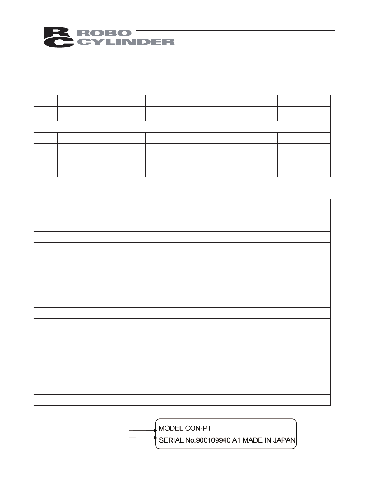
2. Operation manual related to this product, stored in the CD/DVD
1 Operation manual for touch-panel teaching pendant CON-PT/CON-PD/CON-PG ME0227
2 Operation manual for actuator integrated with ERC2 controller (PIO type) ME0158
3 Operation manual for actuator integrated with ERC2 controller (SIO type) ME0159
Refer to "How to Read Model Nameplate" and
"How to Read Model Number."
rebmunlortnoCemaN.oN
4 Operation manual for actuator integrated with ERC3 controller ME0297
5 ME0289
Operation manual for PCON-CA controller
6 Operation manual for PCON-C/CG/CF controller ME0170
7 Operation manual for PCON-CY controller
8 Operation manual for PCON-SE controller ME0163
9 Operation manual for PCON-PL/PO controller ME0164
10 Operation manual for ACON-C/CG controller ME0176
11 Operation manual for ACON-CY controller ME0167
12 Operation manual for ACON-SE controller ME0171
13 Operation manual for ACON-PL/PO controller ME0166
14 Operation manual for SCON controller ME0161
15 Operation manual for SCON-CA ME0243
16 Operation manual for ROBONET ME0208
17 Operation manual for ASEP/PSEP/DSEP controller ME0216
18 Operation manual for PMEC/AMEC controller
3. How to Read Model Nameplate
ME0156
ME0245
Model numbe
Serial number
r
9
Page 16
4. How to Read Model Number
CON - PT - M - ENG
<Model number>
CON-PT: Standard type
CON-PD: With deadman switch
CON-PG: With safety category 4 switch
<Display color>
M: Monochrome LCD (3 backlight colors)
Supported Models
The table below lists supported models.
Controller model
List of Supported Models
ERC2*
ERC3*
1
3
ACON
PCON
PCON-CA*
SCON*
3
2
<Option>
Not specified: Screens are displayed in Japanese.
(Display can be changed to English)
ENG: Screens are displayed in English.
(Display can be changed to Japanese)
JCH: Screens are displayed in Japanese.
(Display can be changed to Chinese)
CHJ: Screens are displayed in Chinese.
(Display can be changed to Japanese)
ECH: Screens are displayed in English.
(Display can be changed to Chinese)
CHE: Screens are displayed in Chinese.
(Display can be changed to English)
Controller model
RPCON
ASEP
PSEP
AMEC
PMEC
DSEP*
3
RACON
*1 Whether or not ERC2 is supported can be checked on the sticker attached to the left side face of the cover
(as viewed from the rear).
Information on sticker
I/O type Not supported Supported
NP NP U5 M NP T1 4904
PN PN U3 M PN T1 4904
Note that touch-panel teaching pendants can be connected to ERC2 controllers of SIO type via a SIO converter
regardless of their version.
*2 SCON-CA is supported from version 1.20.
*3 ERC3, PCON-CA and DSEP are supported from version V1.50.
10
Page 17
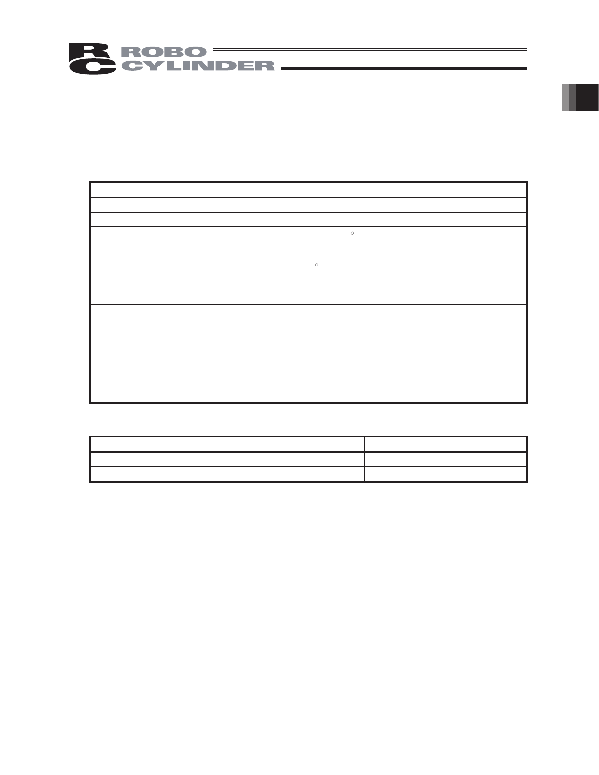
1. Basic Specification
This touch-panel teaching pendant is a display operation unit you can use to display or edit data
saved in the controller as a result of communication with the controller (parameter data, position data,
etc.). This unit is used for checking teaching alarms or performing other tasks in an offline state when
no host PLC, etc., is connected.
snoitacificepSmetI
emorhconoM LCD type
Power consumption 2.4 W or less (100 mA or less)
Surrounding air
temperature, humidity
Ambient storage
temperature, humidity
Vibration resistance
Impact resistance 98 m/s2 or more, applied 4 times each in X, Y and Z directions
Environmental
resistance
Dimension 180 mm (H) x 132 mm (W) x 92.1 mm (D)
Mass Approx. 780 g (including 5 m of cable)
Cable length 5 m (standard)
Temperature -20 to 60
10 to 55 Hz (1-minute period) based on reversed amplitude of
Temperature 0 to 50
C, humidity 10 to 85% RH (non-condensing)
0.75 mm in X, Y and Z directions for 10 minutes
IP 40 or equivalent
C, humidity 20 to 85% RH
(non-condensing)
hcuoTseirosseccA pen
%DVLF6SHFL¿FDWLRQ
Language Change
Displayed Language (in Delivery)Model
EnglishCON-PT-M-ENG
CON-PT-M-ECH English
Available Language
Japanese
Chinese
11
Page 18
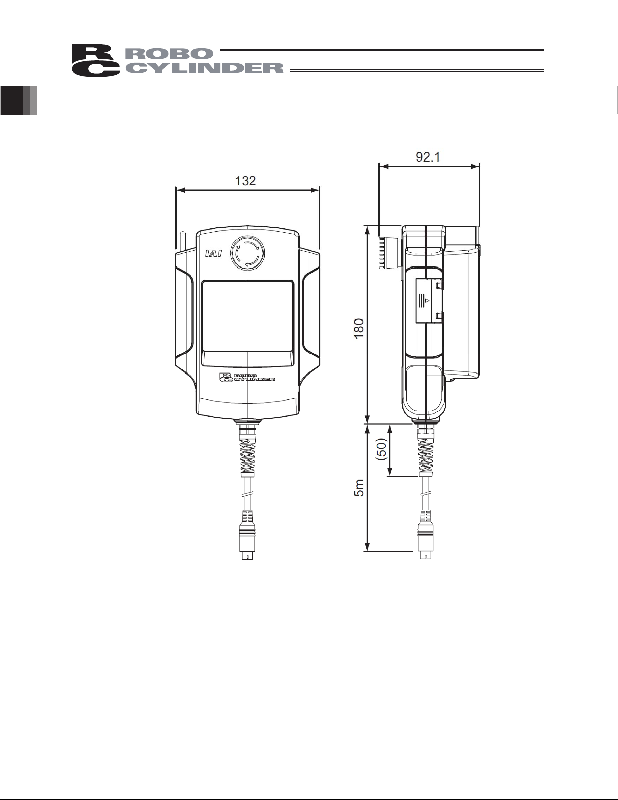
External Dimensions
%DVLF6SHFL¿FDWLRQ
12
Page 19
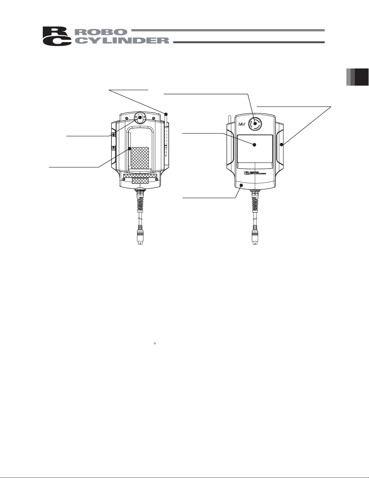
2. Explanation of Each Part
[3] Touch pen
[4] Wall-mounting
hook
[6] Dead-man Switch
(CON-PD, PG)
[1] Touch-panel operation display screen
The screen consists of a STN monochrome LCD and a touch panel.
Various settings that have been edited or taught are displayed.
To operate the screen, use a finger or the touch pen to touch
panel.
[2] EMERGENCY STOP (pushbutton
switch for emergency stop)
[1] Touch panel
operation
display screen
[5] Strap securing part
(Note 1)
desired parts of the touch
(Note) Do not open this lid.
2. Explanation of Each Part
(for future expansion)
(Note 1) This touch panel is of analog resistance membrane type, so do not touch two or more
locations on the screen at the same time.
If two or more locations are touched at the same time, the centers of all touched
locations may respond and trigger multiple operations.
(Note 2) When operating the touch panel, do not apply a force exceeding 0.5 N.
If any greater force is applied, the touch panel may be damaged.
(Note 3) The life of touch panel is approx. 1 million touches at the same location. (Assuming a
use environment of 25
C)
[2] EMERGENCY STOP (Pushbutton switch for emergency stop)
This switch actuates an emergency stop.
[3] Touch pen
This touch pen is used to touch the touch-panel operation display screen.
[4] Wall-mounting hook
This hook is used to mount the touch panel on a wall.
[5] Strap securing part
This part is used to attach a strap (optional).
13
Page 20

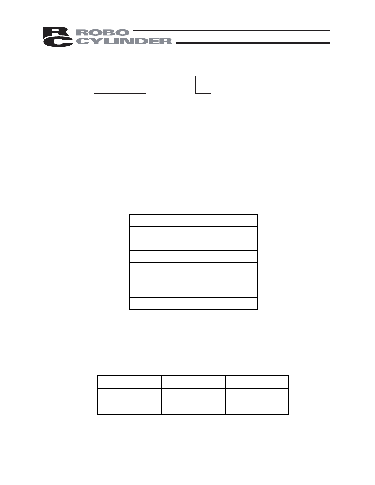
[6] Dead-man Switch (CON-PD, PG)
There are three stages for the dead-man switch. The ON/OFF in each stage are described as
follows.
1st Stage
2nd Stage
3rd Stage
The servo-motor can be turned ON under the switch ON condition.
When the switch is turned OFF, the driving power source is disconnected and the servo-motor is
turned OFF.
Even when the switch is turned OFF, the operations in the modes where turning ON the
2. Explanation of Each Part
servo-motor is not required are available. (such as edit mode)
Switch OFF
Switch ON
Switch OFF
The condition where finger is released from the switch, or the
force of pressing the switch is very weak.
Condition where the switch is pressed with appropriate force.
Condition where the switch is pressed strongly.
14
Page 21
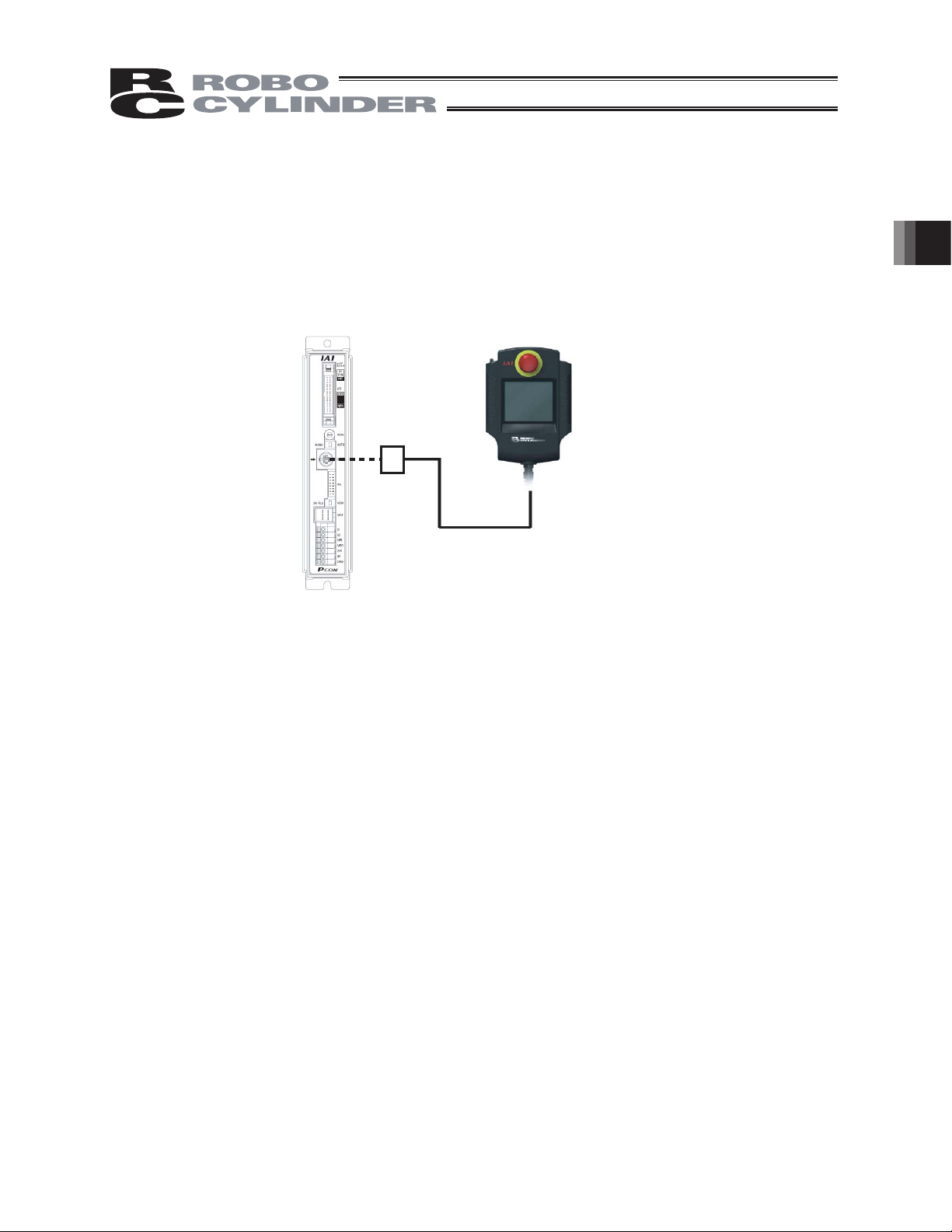
3. Connection and Disconnection to/from Controller
The touch-panel teaching pendant CON-PT can be connected or disconnected without turning off the
controller power first.
If an alarm occurs, the CON-PT can be connected while the controller power is still supplied, to check
the details of the alarm.
3. Connection and Disconnection to/from Controller
Controller
CON-PT, PD
15
Page 22
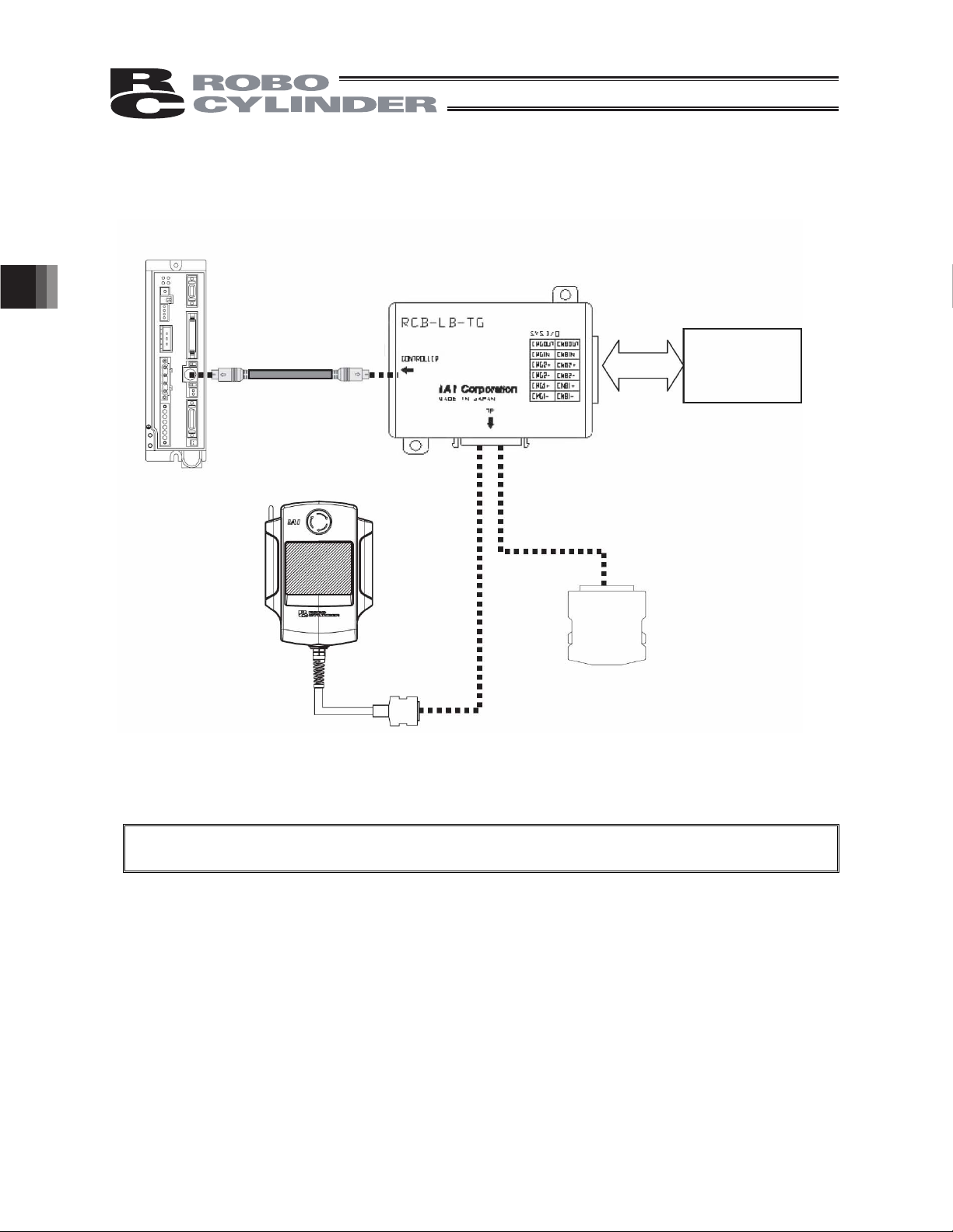
4. Connection of CON-PG and Controller
Controller
Controller-adapter
connection cable
Model: CB-CON-LB
Teaching pendant
CON-PG
4. Connection of CON-PG and Controller
Teaching pendant adapter
RCB-LB-TG
Safety circuit
(relay, safety
relay)
Dummy plug
DP-4
Caution: While the teaching pendant CON-PG is not connected, be sure to connect the dummy plug
DP-4 to the teaching pendant adapter.
16
Page 23
5. Operation of CON Controllers
CON controllers: ERC2, ERC3 (CON Mode), ACON, PCON, SCON-C, SCON-CA, RACON, RPCON
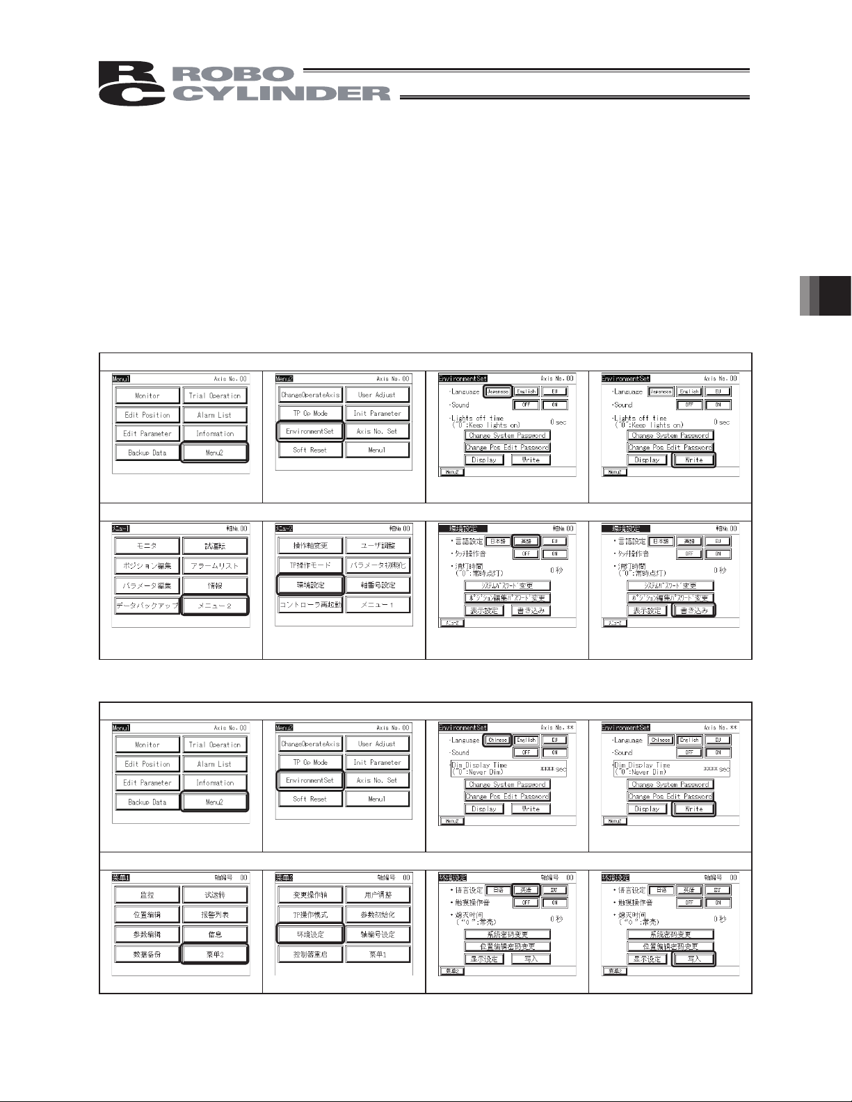
5.1 Displayed Language Change
The language can be changed by following the steps below.
For the operations after the language change, please refer to the instruction manual written in each
language.
Model: CON-PT-M-ENG CON-PT-M-JCH
Display change from English to Japanese
5. Operation of CON Controllers
Touch [Menu2] in Menu1.
Touch [EnvironmentSet] in
Menu2.
Display change from Japanese to English
Touch [
࠾ࡘ
ࡔ࠾ࡘ
1.
2] in
ࡔ
Touch [
࠾ࡘ
ⅣႺ⸳ቯ
2.
Model: CON-PT-M-ECH CON-PT-M-CHE
Display change from English to Chinese
Touch [Menu2] in Menu1.
Touch [EnvironmentSet] in
Menu2.
Display change from Chinese to English
]in
ࡔ
Touch [Japanese]. Touch [Write]
Touch [
Touch [Chinese]
⧷⺆]
Touch [
Touch [Write]
ᦠ߈ㄟߺ]
Touch [
㦰
2] in
㦰
Touch [
1.
⦃๗䆒ᅮ
]in
㦰
2.
Touch [
]. Touch [
㣅䇁
ݭܹ]
17
Page 24
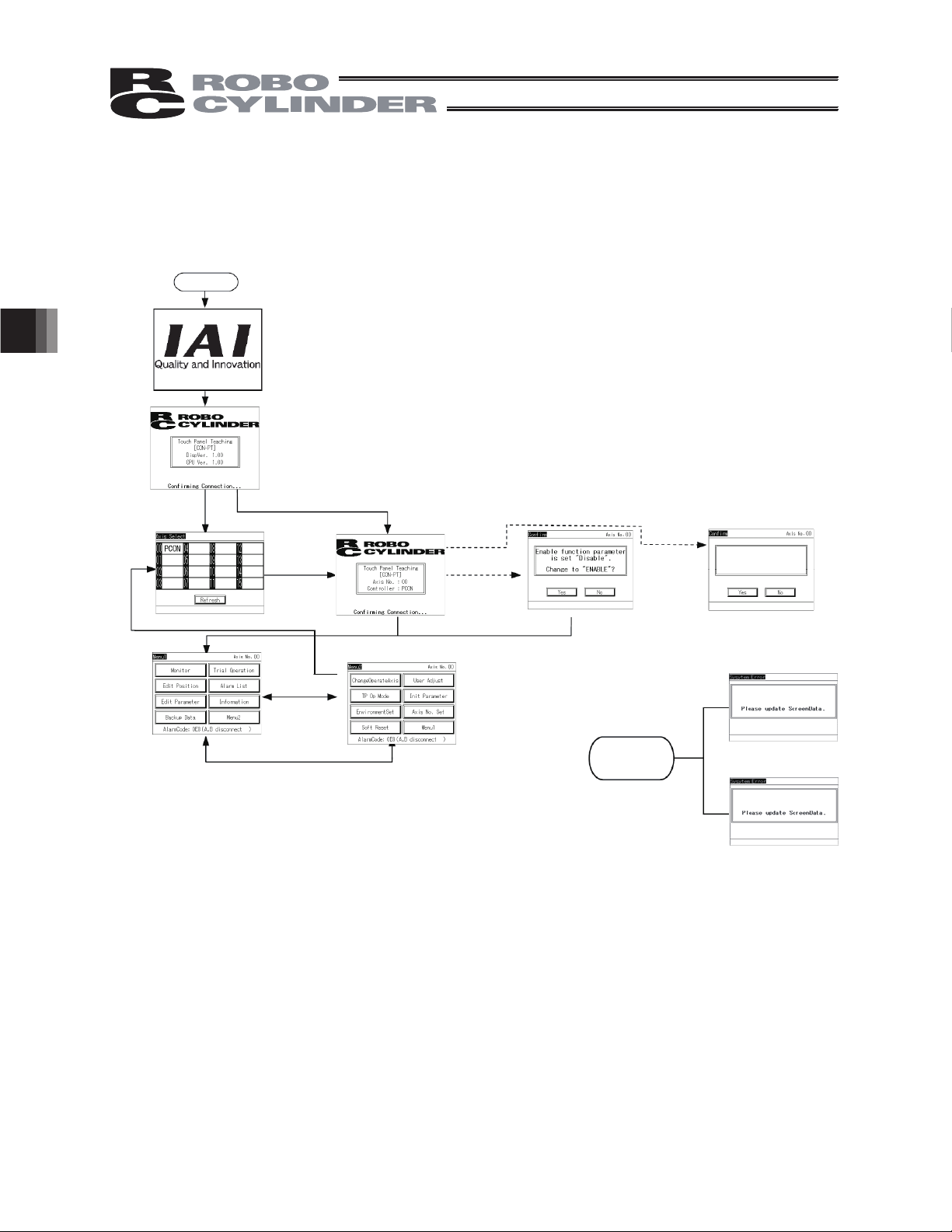
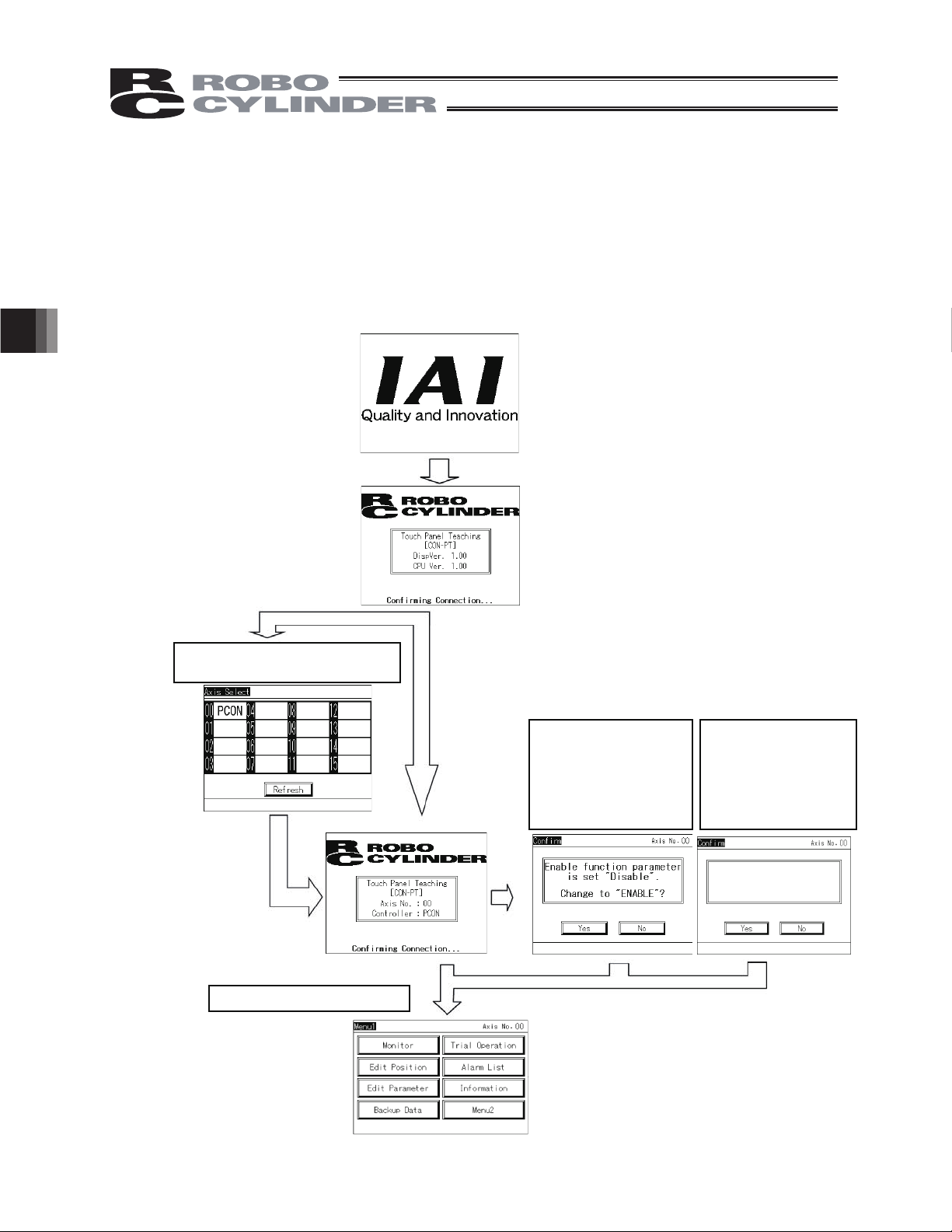
5.2 Transition of Operating States
y
Transition of operating states when the touch-panel teaching pendant CON-PT is connected to a
CON controller is shown.
Power ON
Title display
* Displayed for 1
second.
Version displa
If multiple axes are
connected
5. Operation of CON Controllers
Axis selection
Menu-1
Menu-2
This screen appears
when the enable
function is disabled on
a controller CON-PT,
PD or PG.
This screen
appears when the
enable function is
enabled on a
controller CON-PT.
If the versions do
not match
Enable function parameter
is set “Enable” .
Change to “Disable” ?
Screen version does not match
sub CPU board version.
Sub CPU board version does
not match screen version.
18
Page 25
r
Menu-1
Monito
Models other than SCON-CA
When an editing
password is entered
Main monitor
SCON-CA (CON-PT version 1.20 or later)
Main monitor
SCON-CA (CON-PT Version 1.30 or Later), ERC3, PCON-CA (Version 1.50 or Later)
Main monitor
Position editing
IO monitor
IO monitor
IO monitor
Maintenance information screen
Data monitor
Data monitor
Data monitor
Maintenance information screen in edit mode Maintenance information screen in edit modeMaintenance information screen
LC monitor
LC monitor
When the [Time]
switch is pressed on
the monitor screen
[Display shown only for SCON-CA]
PCON-CFA
5. Operation of CON Controllers
Password entry
[All Clear]
Alarm List
Models other than SCON-CA
SCON-CA
Position editing
– Multiple position view
Alarm List
Position editing
– Individual position view
[Clear]
Alarm List
Position editing
– Jog operation
[Import]
[Erase]
Position editing
– Inching operation
19
Page 26

If the system password
function is enabled
Menu-1
Edit Parameter
Password entry
[Menu-1]
Trial operation
(Note)
5. Operation of CON Controllers
If a change is made
I/O test is available
in V1.20 or later
Parameter editing
Jog operation
Position movement
Parameter editing
Inching operation
Direct movement
If a controller alarm
generates
If a TP alarm or
message generates
[Inquiry]
Parameter editing
Please turn on the power again.
20
V1.20 or laterI/O test
Information
Backup Data
Page 27
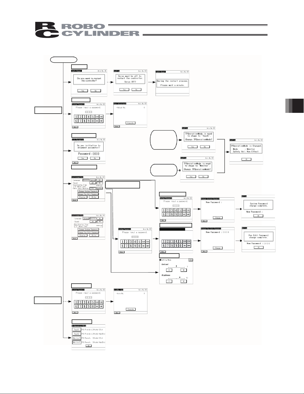
If the system password
function is enabled
Menu-2
Soft Reset
User Adjust
5. Operation of CON Controllers
Password entry
Int. Parameter
Environment Set
Display for Japanese/English/EU languages setting change
(Option model code : ENG)
Display for Chinese/English/EU
languages setting change
(Option model code : ECH)
Version V1.30 or later
User adjustment
If the system password
function is enabled
If an attempt is
made to change to
the “position data,”
“movement” or “user
parameter” screen
when the TP
operation mode is
Monitor
If an attempt is made to
change to the “monitor”
screen when the TP
operation mode is
Teaching
System Password
Change Pos Edit Password
Change Pos Edit
New Password: 0000
Display
5119
5119
If the system password
function is enabled
Axis No. Set
Password entry
TP Op Mode
Axis number setting
21
Page 28
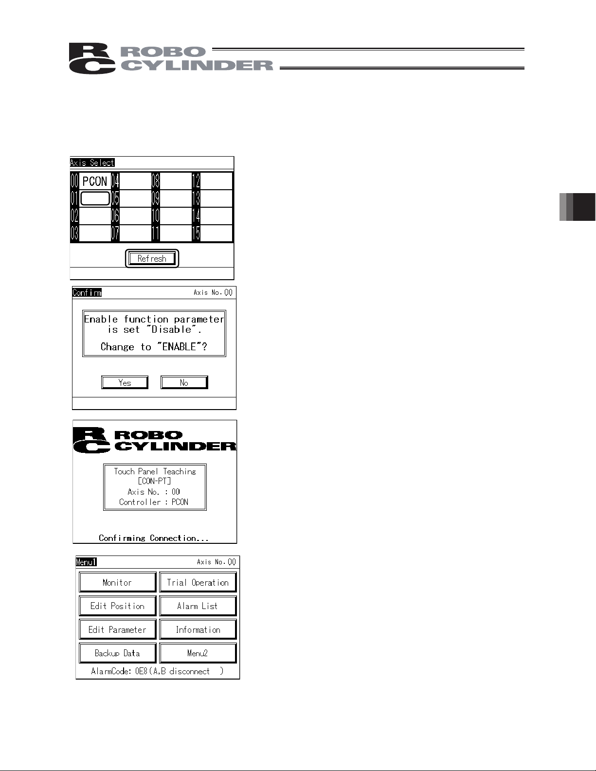
5.2 Initial Screen
5.3
Upon connection to the controller, power is supplied to the touch-panel teaching pendant and
processing starts.
When the power is turned on, the IAI logo is displayed for approx. 1 second on the operation display
screen (hereinafter referred to as "operation screen") of the touch-panel teaching pendant, after
which version information is displayed.
5. Operation of CON Controllers
If multiple units are connected, the
axis selection screen appears.
PCON
Select the axis you want
to connect.
[Refer to 5.3, "Changing
Operating Axis."]
The Menu 1 screen appears.
On CON-PD/PG
pendants, this screen is
displayed when the
enable function
parameter of the
controller is set to
“Disable.”
Select [Yes] (Enable) or
[No] (Disable) for the
enable function
On CON-PT pendants,
this screen is displayed
when the enable
function parameter of
the controller is set to
“Enable.”
Enable function parameter is
set “Enable” .
Change to “Disable” ?
Select [Yes] (Disable) or
[No] (Enable) for the
enable function
22
Page 29
5.4
5.3 Changing Operating Axis
If multiple controllers are connected to the communication line, the axis selection screen appears.
This screen also appears when [Change Operate Axis] is touched on the Menu 2 screen.
If only one controller is connected, you need not select an axis.
Select and touch the axis you want to connect the touchpanel teaching pendant to.
PCON
ACON
This screen appears when the enable function parameter of
the controller, other than CON-PT, is set to [Disable].
Select and touch [Yes] (Enable) or [No] (Disable) for the
enable function.
5. Operation of CON Controllers
Connection with the selected controller axis starts.
When connection with the controller is established, the Menu
1 screen appears.
23
Page 30
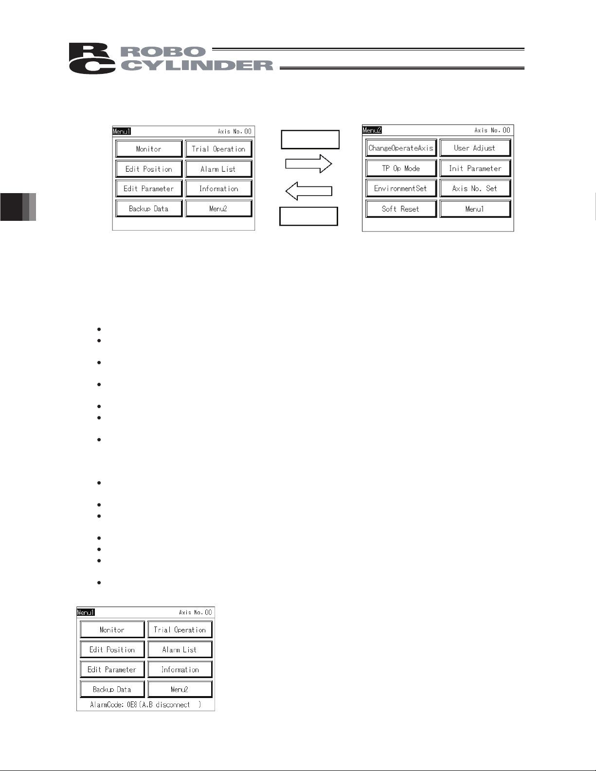
5.4 Menu Selection
5.55.5
Two menu selection screens, Menu 1 and Menu 2, are available.
Touching [Menu2] on the Menu 1 screen changes the display to the Menu 2 screen.
Touching [Menu1] on the Menu 2 screen changes the display to the Menu 1 screen.
The Menu 1 screen and Menu 2 screen provide seven menu items, respectively. Select and touch
one of these items.
The screen changes to the one corresponding to the menu item you have touched.
Menu 1 list
Monitor Display the controller status. [Refer to 5.6, "Monitor."]
Edit Position Display and edit the position data table. [Refer to 5.7, "Position
Edit Parameter Display and edit zone boundary+ and other parameters. [Refer to
5. Operation of CON Controllers
5. Operation of CON Controllers
Trial Operation Perform operation test for jogging, inching and axis movement.
Alarm List Display alarm details. [Refer to 5.11, "Alarm List."]
Information Display controller information such as the version. [Refer to 5.16,
Backup Data Transfer data between the memory of the touch-panel teaching
2uneM1uneM
Menu 2
Menu 1
Editing."]
5.8, "Parameter Editing."]
[Refer to 5.9, "Trial Operation."]
"Information."]
pendant and the controller. [Refer to 5.18, "Data Backup."]
24
Menu 2 list
Change Operating Axis Select the controller axis to connect the touch-panel teaching
pendant to. [Refer to 5.4, "Changing Operating Axis."]
Soft Reset Restart the controller. [Refer to 5.12, "Restarting Controller."]
TP Op Mode Select a desired TP operation mode. [Refer to 510, "TP Operation
Mode."]
User Adjust Execute home return, etc. [Refer to 5.13, "User Adjustment."]
Init Parameter Initialize parameters. [Refer to 5.14, "Parameter Initialization."]
Axis No. Set Set the axis number of the controller. [Refer to 5.15, "Axis Number
Setting."]
Environment Set Set the language and touch tone, change the system password, etc.
[Refer to 5.17, "Environment Setting."]
When an alarm generates, the corresponding alarm code and
message will appear at the bottom of the screen and the
backlight color will change to pink. If an emergency stop is
detected, the backlight color will change to red.
Page 31

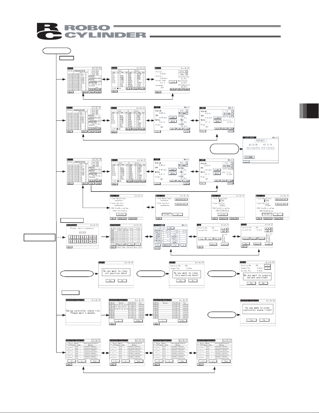
5.6
5.6 Monitor
The I/O statuses, current position and other information of the controller connected to the serial
communication line are displayed.
Touch [Monitor] on the Menu 1 screen.
If the TP operation mode is not Monitor Mode 1 or 2, the following message screen appears.
Touch [Yes] to change to Monitor Mode 1 or 2.
If not, touch [No].
(Note) The safety speed does not change.
If the current mode is Teaching Mode 1, it changes to
Monitor Mode 1.
If the current mode is Teaching Mode 2, it changes to
Monitor Mode 2.
Touch [OK].
5. Operation of CON Controllers
Models other than SCON-CA, PCON-CA, ERC3
SCON-CA (CON-PT version 1.20 or later, but before 1.30)
PCON-CA, ERC3
The main monitor screen appears.
SCON-CA (CON-PT version 1.30 or later)
Maintenance information can be displayed.
25
Page 32

The main monitor screen appears.
Models other than SCON-CA, PCON-CA, ERC3
PCON-CA, ERC3 (CON-PT version 1.5 later)
5. Operation of CON Controllers
Touching [IOMoni] changes the display to one
showing only I/Os.
Touching [DataMon] changes the display to one
showing only the current position, etc.
Touching Axis No. switches to the axis selection
screen.
Touching [IO Mon] changes the display to show only
IOs.
Touching [Maintenance] changes the display to show
maintenance information.
Touching [Data Mon] changes the display to show
data such as the current position and control voltage.
Touching [Time] shows the window for time edit adjustment.
Touching [Axis No.] switches the screen to one
where you can select an axis.
SCON-CA (CON-PT version 1.20 or later, but before 1.30)
Touching [IO Mon] changes the display to show only
IOs.
Touching [Data Mon] changes the display to show
data such as the current position and control voltage.
Touching [LC Mon] changes the display to show data
such as the current position and force feedback.
Touching [Time] shows the window for time edit adjustment.
Touching [Axis No.] switches the screen to one
where you can select an axis.
26
Page 33

SCON-CA (CON-PT version 1.30 or later)
Touching [IO Mon] changes the display to show only
IOs.
Touching [Maintenance] changes the display to show
maintenance information.
Touching [Data Mon] changes the display to show
data such as the current position and control voltage.
Touching [LC Mon] changes the display to show data
such as the current position and force feedback.
Touching [Time] shows the window for time edi
adjustment.
.
Touching [Axis No.] switches the screen to one
where you can select an axis
[Displayed Items]
x IO Pattern The PIO pattern number set to the controller is shown.
x Complete Pos No The position number achieved upon completion of positioning is shown.
x IN The status of each input port is shown. ON is lit. OFF is unlit.
x OUT The status of each output port is shown. ON is lit. OFF is unlit.
x Special Input The statuses of the enable switch, etc., are shown. ON is lit. OFF is unlit.
(The displayed items vary depending on the model.)
x Servo The servo ON status is shown. ON is lit. OFF is unlit.
x Home The home return status is shown. Lit, if home return has completed.
x Position The current position is shown.
x Velocity The speed is shown.
x Current Rate The command value of electrical current is shown as a percentage of the rated
current.
x Alarm Code The applicable alarm code is shown.
5. Operation of CON Controllers
27
Page 34

Models other than SCON-CA, PCON-CA, ERC3
IO monitor screen
Touching [MoniMain] switches to the main monitor
display.
Touching [DataMoni] changes the display to one
showing only the current position, etc.
Touching Axis No. switches to the axis selection
screen.
x Input The status of each input port is shown. ON is lit. OFF is unlit.
x Output The status of each output port is shown. ON is lit. OFF is unlit.
Models other than SCON-CA, PCON-CA, ERC3
Data monitor screen
5. Operation of CON Controllers
Position The current position is shown.
Position The current position is shown.
x
Velocity The speed is shown.
Velocity The speed is shown.
x
Pulse count The pulse count is shown. Touching [Pulse Count] displays the pulse count. (It’ll
Pulse count The pulse count is shown. Touching [Pulse Count] displays the pulse count. (The pulse
x
Current Rate The command value of electrical current is shown as a percentage of the rated
Current Rate The command value of electrical current is shown as a percentage of the rated current.
x
Current The command value of electrical current is shown. Touch [Current Rate] to display the
x
Current The command value of electrical current is shown. Touch [Current] to display the
AlarmCode The applicable alarm code is shown.
x
Alarm Code The applicable alarm code is shown.
Servo The servo ON status is shown. ON is lit. OFF is unlit.
x
Servo The servo ON status is shown. ON is lit. OFF is unlit.
Home The home return status is shown. Lit, if home return has completed.
x
Home The home return status is shown. Lit, if home return has completed.
ControlVoltage The voltage of the control power supply is shown.
x
Control Voltage The voltage of the control power supply is shown.
MotorVoltage The voltage of the motor power supply is shown.
x
Motor Voltage The voltage of the motor power supply is shown.
PCB Temperature The PCB temperature is shown.
x
PCB Temperature The PCB temperature is shown.
Touching [MoniMain] switches to the main monitor
display
Touching [IOMoni] changes the display to one
showing only I/Os.
Touching Axis No. switches to the axis selection
screen.
Touch [Current] to display [Current Rate].
Touch [Current Rate] to display [Current]
be shown in the pulse-train control controller mode such as PCON-PL/PC.)
count is shown in the pulse-train control mode.)
current.
command value.
command value.
28
Page 35

PCON-CA and ERC3
IO monitor screen
Input The status of each input port is shown. ON is lit. OFF is unlit.
Output The status of each output port is shown. ON is lit. OFF is unlit.
PCON-CA and ERC3
Data monitor screen
Touching [Mon Main] switches to the main monitor
display
Touching [Data Mon] changes the display to show
data such as the current position and control voltage.
Touching [Axis No.] switches the screen to one
where you can select an axis.
5. Operation of CON Controllers
Touching [Mon Main] switches to the main monitor
display
Touching [IO Mon] changes the display to one
showing only I/Os.
Touching [Axis No.] switches the screen to one
where you can select an axis.
Touch [Current] to display [Current Rate].
Touch [Current Rate] to display [Current].
Position The current position is shown.
Velocity The speed is shown.
Pulse count The pulse count is shown. Touching [Pulse Count] displays the pulse count.
(The pulse count is shown in the pulse-train control mode.)
Current Rate The command value of electrical current is shown as a percentage of the rated
current.
Current The command value of electrical current is shown. Touch [Current Rate] to
display the command value.
Alarm Code The applicable alarm code is shown.
Servo The servo ON status is shown. ON is lit. OFF is unlit.
Home The home return status is shown. Lit, if home return has completed.
MotorVoltage The voltage of the motor power supply is shown.
PCB Temperature The PCB temperature is shown.
29
Page 36

SCON-CA
IO monitor screen
x Input The status of each input port is shown. ON is lit. OFF is unlit.
x Output The status of each output port is shown. ON is lit. OFF is unlit.
SCON-CA
Data monitor screen
5. Operation of CON Controllers
Touching [MoniMain] switches to the main monitor
display
Touching [Data Mon] changes the display to show
data such as the current position and control voltage.
Touching [LC Mon] changes the display to show data
such as the current position and force feedback.
Touching [Axis No.] switches the screen to one
where you can select an axis.
Touching [MoniMain] switches to the main monitor
display
Touching [IOMoni] changes the display to one
showing only I/Os.
Touching [LC Mon] changes the display to show data
such as the current position and force feedback.
Touching [Axis No.] switches the screen to one
where you can select an axis.
Touch [Current] to display [Current Rate].
Touch [Current Rate] to display [Current]
x Position The current position is shown.
Position The current position is shown.
x
x Velocity The speed is shown.
Velocity The speed is shown.
x
x Pulse count The pulse count is shown. Touching [Pulse Count] displays the pulse count.
Pulse count The pulse count is shown. Touching [Pulse Count] displays the pulse count. (The pulse
x
x Current Rate The command value of electrical current is shown as a percentage of the rated
Current Rate The command value of electrical current is shown as a percentage of the rated current.
x
Current The command value of electrical current is shown. Touch [Current Rate] to display the
x
x Current The command value of electrical current is shown. Touch [Current] to display the
AlarmCode The applicable alarm code is shown.
x
x Alarm Code The applicable alarm code is shown.
Servo The servo ON status is shown. ON is lit. OFF is unlit.
x
x Servo The servo ON status is shown. ON is lit. OFF is unlit.
Home The home return status is shown. Lit, if home return has completed.
x
x Home The home return status is shown. Lit, if home return has completed.
MotorVoltage The voltage of the motor power supply is shown.
x
x Control Voltage The voltage of the control power supply is shown.
PCB Temperature The PCB temperature is shown.
x
x Motor Voltage The voltage of the motor power supply is shown.
(The pulse count is shown in the pulse-train control mode.)
count is shown in the pulse-train control mode.)
current.
command value.
command value.
x PCB Temperature The PCB temperature is shown.
30
Page 37

SCON-CA
LC monitor screen
Touching [MoniMain] switches to the main monitor
display
Touching [IOMoni] changes the display to one
showing only I/Os.
Touching [Data Mon] changes the display to show
data such as the current position and control voltage.
Force feedback
10.00 N
x Position The current position is shown.
Position The current position is shown.
x
x Velocity The speed is shown.
Velocity The speed is shown.
x
x Pulse count The pulse count is shown. Touching [Pulse Count] displays the pulse count.
Pulse count The pulse count is shown. Touching [Pulse Count] displays the pulse count. (The pulse
x
x Current Rate The command value of electrical current is shown as a percentage of the rated
Current Rate The command value of electrical current is shown as a percentage of the rated current.
x
Current The command value of electrical current is shown. Touch [Current Rate] to display the
x
x Current The command value of electrical current is shown. Touch [Current] to display the
AlarmCode The applicable alarm code is shown.
x
x Alarm Code The applicable alarm code is shown.
Servo The servo ON status is shown. ON is lit. OFF is unlit.
x
x Servo The servo ON status is shown. ON is lit. OFF is unlit.
Home The home return status is shown. Lit, if home return has completed.
x
x Home The home return status is shown. Lit, if home return has completed.
Calibration The calibration status of the load cell is shown. Lit, if calibration of the load cell has been
x
x Calibration The calibration status of the load cell is shown. Lit, if calibration of the load cell
completed.
Force feedback The force feed back from the load cell is shown.
x
x Force feedback The force feed back from th
(The pulse count is shown in the pulse-train control mode.)
count is shown in the pulse-train control mode.)
current.
command value.
command value.
has been completed.
Touch [Current] to display [Current Rate].
Touch [Current Rate] to display [Current]
e load cell is shown.
5. Operation of CON Controllers
31
Page 38

SCON-CA (CON-PT version 1.30 or later), PCON-C, ERC3 (CON-PT version 1.50 or later)
Maintenance information screen
PCON-CFA
5. Operation of CON Controllers
Touching [Info Edit] switches the screen to one
where you can edit maintenance information.
• Total number of movements The cumulative total number of actuator movements is shown.
••Total travelled distance The cumulative total distance travelled by the actuator is shown.
Total fan driving time Shows the total driving time of the fan on the controller
The above values can be changed on the maintenance information editing screen.
[Thresholds for Total Number of Movements and Total Travelled Distance]
You can set thresholds for total number of movements and total travelled distance in the parameters specified
below, to cause an alarm to generate when each threshold is exceeded.
emaN.oNretemaraP
147 Threshold for total number of movements
148 Threshold for total travelled distance
Message-level alarms
Alarm code
4E
Movements threshold
exceeded
This alarm generates when the total
number of movements exceeds the
noitpircseDemaN
threshold set in parameter No. 147.
This alarm generates when the total
travelled distance exceeds the threshold
set in parameter No. 148.
4F
Travelled distance
threshold exceeded
32
Page 39

(1) Editing maintenance information
SCON-CA, PCON-CA, ERC3
PCON-CFA
Touching [Moved Count Edit] or [Run Dist. Edit]
displays the keyboard screen.
Enter a desired value and press [ENT], and the
current setting will change to the value you have
entered.
Touching [Set] display returns you to the previous
maintenance information screen.
5. Operation of CON Controllers
Touching [Display Information] without touching [Set]
first returns you to the maintenance information
screen showing the original value. The setting will not
change to the value you have entered.
33
Page 40

With SCON-CA, PCON-CA, ERC3 PIO converter controllers, you can set the controller time.
[How to Set Time]
5. Operation of CON Controllers
Touching [Time] displays the time setting screen.
Touch [Edit Time].
Touch the value of year, month, day, hours, minutes or seconds you
want to change.
34
The numeric key pad appears. Enter a desired value, and then press
[ENT].
Touch [Set].
The current time on the SCON-CA, PCON-CA, ERC3 PIO converter
controller is changed.
Page 41

5.7
5.6 Position Editing
Set/edit the target position, speed, acceleration, deceleration and other data related to positions. You
can move the axis by jogging or inching.
Touch [Edit Position] on the Menu 1 screen.
If a position password is set, the password setting screen appears.
Enter the position password.
The default password is "0000."
A position data table appears.
5. Operation of CON Controllers
Position No.
Data of the selected position number appears.
Version V1.20 and Earlier
Touching [Multi Pos] returns the screen to the position data
table display.
Version V1.20 or later
100.00
120.00
0.30
0.10
0
0.10
0
60.00
40.00
0
0
0
0
0
Touch Specify No. to set the position number
you want to set, and a table showing the
position number you have just set appears.
To set data other than the target position,
speed, acceleration and deceleration shown in
the table, touch other position number such as
"000."
35
Page 42

5.7.1
S-motion
Vibration
Control
×
×
×
×
{
×
{
×
×
×
{
×
×
×
×
×
{
×
{
×
{
×
{
×
{
{
5.6.1 Position Data
5.7.1
Position data table screen
Data display screen showing the selected position number
Version V1.20 and Earlier
Version V1.20 or later
5. Operation of CON Controllers
The items set in the position data table include target position, speed, acceleration, deceleration,
push, positioning band, incremental, zone+, zone-, threshold, acceleration/deceleration mode, stop
mode and command mode.
The settings of zone+, zone-, threshold, acceleration/deceleration mode and stop mode are enabled
or disabled depending on the controller type, as shown in the table.
Position table Zone +/-
ERC2
ERC2-SE
ERC3
ERC3PIO Converter
PCON-C/CG/CF
PCON-CA
-CY
-SE
ACON-C/CG
-CY
-SE
SCON-C positioner
mode
SCON-CA positioner
mode
36
100.00
120.00
0.30
0.10
0.10
60.00
40.00
0
0
0
{
{
{
{
{
{
{
{
{
{
{
{
{
PIOpattern:0,1,2,4,5,6,7
0
0
0
0
PIO pattern: 3
-
PIO pattern: 2
PIO pattern:0,1,2,4,5
PIO pattern:0,1,2,4,5
PIO pattern:0,1,2,4,5
PIO pattern: 1
-
PIO pattern:0,1,2,4,5
PIO pattern: 1
-
PIO pattern:0,1,2,4,5
Trapezoid
{
{
{
{
{
{
{
{
{
{
{
{
{
AccDcl Mode Stop mode
Primary
delay
×
×
{
{
×
{
×
×
Servo
Autom atic
Full
servo
OFF
{{
{
{{
{{
{{
{{
{{
{
{{
{{
{
{{
{{{
Gain set
×
××
×
×
×
×
×
××
×
×
××
×
Page 43

(1) No.
The position data number is shown.
Warning: Be sure to specify absolute coordinates on PCON-C/CG, ACON-C/CG, SCON-C,
PCON-CA, ROBONET and ERC3 PIO converter controllers of solenoid valve mode 2,
or PCON-CY and ACON-CY controllers of solenoid valve mode 1.
If incremental coordinates are specified on these controllers, a position data error
occurs.
Also note that completion of push motion cannot be determined when the push is
specified if incremental coordinates are specified.
(2) Target position [mm]
Enter the target position to move the actuator to.
Absolute coordinate specification: Enter the target position you want to move the actuator to, based
on the distance from the home. A negative value cannot be
entered.
••Incremental coordinate specification: Enter the target position you want to move the actuator to, based
on the distance from the current position. A negative value can
also be entered.
(Negative direction on displayed coordinate system)
(3) Speed [mm/sec]
Enter the speed at which to move the actuator.
The default value varies depending on the actuator type.
(Note) For SCON-CA, PCON-CA and ERC3, an alarm will be displayed if the set value is lower than the
minimum velocity.
(4) Acceleration/deceleration [G]
Enter the acceleration/deceleration at which to move the actuator.
Basically you should set acceleration/deceleration not exceeding the rated value shown in the catalog.
The input range permits entry of values larger than the rated value shown in the catalog, but this is because
"shorter tact time when the transferring mass is significantly lighter than the rated value" is assumed.
If the load vibrates during acceleration/deceleration to present problems, decrease the value set here.
(Reference) Acceleration is explained. The same concept applies to deceleration.
1 G = 9800 mm/s
per second.
0.3 G: Acceleration at which the actuator can increase its speed up to 2940 mm/s (9800 mm/s
x 0.3) per second.
2
: Acceleration at which the actuator can increase its speed up to 9800 mm/s
Speed
5. Operation of CON Controllers
Time
(Note) For SCON-CA, PCON-CA and ERC3, an alarm will be displayed if the set value exceeds
the rated acceleration/deceleration.
Caution
Acceleration/deceleration setting
(1) Set accelerations/decelerations not exceeding the rated acceleration/deceleration specified in the catalog or
this operation manual. If any acceleration/deceleration is set that exceeds the rated
acceleration/deceleration, the life of the actuator may be significantly reduced.
(2) If the actuator or work part receives impact or generates vibration, lower the acceleration/deceleration. If the
system is used continuously with the actuator or work part receiving impact or generating vibration, the life
of the actuator may be significantly reduced.
(3) If the load transferred by the actuator is significantly lighter than the rated payload capacity, you may be
able to set accelerations/decelerations exceeding the rating. If this is the case, the tact time can be
reduced, so contact IAI. When contacting IAI, tell us the weight, shape and installation method of your work
part and installation condition (horizontal/vertical) of your actuator.
37
Page 44

(5) Push
Select "Positioning operation" or "Push-motion operation."
The factory setting is 0.
0: Normal positioning operation
Other than 0: A current limiting value is indicated, meaning that this is a push-motion operation.
Caution: With PCON, ACON, SCON-C, SCON-CA, ERC2,ERC3 and ROBONET controllers,
the value entered in the "Push" field may be rounded to a multiple of the controller's
minimum resolution. (When data is acquired from the controller)
(6) Positioning band
What this setting means is different between "Positioning operation" and "Push-motion operation."
"Positioning operation":
Define how far before the target position you want to turn the completion signal ON.
The factory setting is 0.1 mm.
Standard type
Increasing the value of positioning band quickens the start of
the next sequence operation, so the tact time can be
reduced. Set an optimal value by considering the balance of
the entire system.
5. Operation of CON Controllers
Note that on PCON-C/CG, ACON-C/CG, SCON-C, SCON-CA, ROBONET and ERC3 PIO converter controllers
of 3-point type or PCON-CY and ACON-CY controllers of proximity switch type, set the band after which
the completion signal turns ON.
PCON-C/CG, ACON-C/CG and SCON-C, SCON-CA, ROBONET and ERC3 PIO converter in solenoid
valve mode 2, PCON-CY, or ACON-CY in solenoid valve mode 1
"Push-motion operation":
Define the maximum push distance from the target position in push-motion operation.
Set an appropriate positioning band by considering the mechanical variation of the load, by making sure
positioning will not complete before the actuator contacts the load.
Completion signal
Timing at which the
completion signal turns ON
Positioning band
Positioning band
Target
position
Target
position
38
Position at which the load is contacted and completion of
push-motion operation is deemed complete and therefore
the completion signal turns ON
Load
Positioning band ON
Target position
(Maximum push distance)
Page 45

(7) Incremental
Specify absolute coordinates or incremental coordinates.
The factory setting is 0.
0: Absolute coordinate specification
1: Incremental coordinate specification
Warning: Be sure to specify absolute coordinates on PCON-C/CG, ACON-C/CG and SCON-C
SCON-CA, ROBONET and ERC3 PIO converter controllers of solenoid valve mode 2,
or PCON-CY and ACON-CY controllers of solenoid valve mode 1.
If incremental coordinates are specified on these controllers, a position data error
occurs.
(8) Zone +/-
Define, for the standard type, the zone in which the zone output signal turns ON.
For added flexibility, these parameters can be set differently for each target position.
[Setting example]
No. Position [mm] Zone + [mm] Zone - [mm] Remarks
0 5.00 100.00 0.00 Backward end
1 380.00 400.00 300.00 Forward end
2 200.00 250.00 150.00
Intermediate
position
Movement command to backward end
5. Operation of CON Controllers
Backward
Home
end
Zone output signal
Movement command to forward end
Forward
end
Zone output signal
Movement command to intermediate position
Midway
point
Zone output signal
(9) Threshold
With PCON-CF controllers, a load output signal (PIO) is output if the command torque exceeds the
value (%) set in "Threshold" inside the verification range.
The verification range is set by "Zone+/Zone-."
It is used to determine if press-fitting action was performed successfully.
* For details, refer to the operation manual for your PCON-CF controller.
39
Page 46

(10) Acceleration/deceleration mode
Define the acceleration/deceleration pattern.
The factory setting is 0.
0: Trapezoid pattern
1: S-motion
2: Primary delay filter
Trapezoid pattern
* Set the acceleration and deceleration in the "Acc" and "Dcl" fields of the position table.
S-motion
The acceleration curve rises gradually at first and then suddenly shoots up in the middle.
Use this mode if you want to set high acceleration/deceleration to meet the required tact time, but
want to move the actuator gradually at the start of movement and immediately before stopping.
5. Operation of CON Controllers
* The S-motion level is set by parameter No. 56 [S-motion ratio setting]. The setting unit is %, while the
setting range is 0 to 100.
(The graph above assumes that the parameter is set to 100%.)
If 0 is set, the S-motion control is disabled.
Note that the setting made here is not reflected in jogging or inching feed performed from a PC or
teaching pendant.
(Note) This setting is not available on ERC2 and PCON controllers. On these controllers, parameter No.
56 is reserved.
Speed
Acceleration
Speed
Deceleration
Time
Time
Primary delay filter
The acceleration/deceleration curve becomes more gradual than linear acceleration/deceleration
(trapezoid pattern).
Use this mode if you don't want to apply fine vibration to the load during acceleration/deceleration.
Speed
Time
* The primary delay level is set by parameter No. 55 [Primary filter time constant for position commands].
The setting unit is 0.1 msec, while the setting range is 0.0 to 100.0.
If 0 is set, the primary delay filter is disabled.
Note that the setting made here is not reflected in jogging or inching feed performed from a PC or
teaching pendant.
(Note) This setting is not available on ERC2 and PCON controllers. On these controllers, parameter No.
55 is reserved.
40
Page 47

(11) Stop mode
Define the power-saving mode to be used while the actuator is standing by after completion of
positioning to the target position set in the "Position" field of the applicable position number.
0: Disable power-saving mode * The factory setting is 0 (Disable).
1: Auto servo OFF mode, with the delay time defined by parameter No. 36
2: Auto servo OFF mode, with the delay time defined by parameter No. 37
3: Auto servo OFF mode, with the delay time defined by parameter No. 38
4: Full servo control mode
Auto servo OFF mode
The servo is turned OFF automatically upon elapse of a specified time after completion of positioning.
(Since holding current does not flow, power consumption is reduced.)
When the PLC issues the next movement command, the servo is turned ON and then the actuator
starts moving.
Movement command
Servo OFF in auto mode
Servo status
(A green LED blinks.)
Servo ON status
Actuator movement
Target position
T: Delay time (in seconds) after the
positioning is completed until the servo
turns OFF. T is set by a parameter.
Full servo control mode
The holding current can be decreased by servo-controlling the pulse motor.
Although the rate of decrease in holding current varies depending on the actuator model, loading
condition, etc., the holding current decreases to approx. one-half to one-quarter.
Note that the servo remains ON, meaning that unwanted position shift does not occur.
The actual holding current can be checked on the current monitor screen of the PC software.
5. Operation of CON Controllers
(12) Command mode (Displayed in Version V1.20 and Earlier)
This field is invalid.
The factory setting is 0.
41
Page 48

(13) Gain settings (This information is displayed on version 1.20 or later.)
(Note) Gains can be set only on SCON-CA controllers.
Six parameters required for servo gain adjustment have been put together into one set.
Four types of settings can be registered, and you can change the servo gain for each positioning operation.
[Parameters constituting each set]
x Servo gain number (position gain)
x Position feed-forward gain
x Speed loop proportional gain
x Speed loop integral gain
x Torque filter time constant
x Current control band number
Setting Operation after completion of positioning Parameter numbers
0 Gain set 0 7, 71, 31 ~ 33, 54
1 Gain set 1 120 ~ 125
2 Gain set 2 126 ~ 131
3 Gain set 3 132 ~ 137
(14) Vibration damping number (This information is displayed on version 1.20 or later.)
(Note) Vibration damping can be set only on SCON-CA controllers.
Vibration (resonance) of the load installed on the actuator is suppressed.
5. Operation of CON Controllers
This function works on three types of vibration.
Three parameters are provided for each type of vibration, and they comprise one set.
In the position table, set a desired parameter set for each position number where vibration damping is
required.
Setting
Vibration damping frequency
(Characteristic frequency)
Parameter numbers
0 Normal position control (no vibration damping) 1 Vibration damping parameter set 1 97 ~ 100
2 Vibration damping parameter set 2 101 ~ 104
3 Vibration damping parameter set 3 105 ~ 108
Caution
(1) Vibration can be suppressed over a frequency range of 0.5 to 30 Hz (target characteristic frequencies).
(2) This function suppresses vibration of the load induced by the actuator connected to this controller. It does
not suppress any other vibration.
(3) This function suppresses vibration in the same direction as the moving direction of the actuator. It does not
suppress vibration in any other direction.
(4) This function does not work during home return and push-motion operation.
(5) This function does not support the pulse-train input mode.
(6) The tact time may increase when a lower vibration frequency is set. If the vibration frequency is approx. 6 Hz
or below, the settling time after positioning becomes at least 150 ms.
42
Page 49

5.7.2
5.6.2 Entering New Data
You can enter new position data in one of four ways.
(1) Numerical input --- Enter position data directly as numerical values from the numerical
keypad on the teaching pendant. (Example of entry: P. 39)
(2) Direct teaching --- Turn off the servo control, move the slider by hand to the target position,
and then acquire the achieved position (current position) into the
position table and specify that position. (Example of entry: P. 47)
(3) Jogging --- Use [Jog+] or[Jog-] to jog the actuator to the target position, and then
acquire the achieved position (current position) into the position data
table and specify that position. (Example of entry: P. 49)
(4) Inching --- Use [Jog+] or[Jog-] to inch the actuator to the target position, and then
acquire the achieved position (current position) into the position data
table and specify that position. (Example of entry: P. 51)
Touching [Jog+] or[Jog-] once moves the actuator by the specified feed
pitch (0.01, 0.10, 0.50, 1.00 or 5.00 (mm)). Touching and holding the key
for 2 seconds will start jogging movement at 1 mm/sec. Thereafter, the
speed increases every second. This way, the actuator can be moved
more finely than when jogged.
Warning: To enter position data after the power is turned on, or enter position data beforehand
using the method of (2), (3) or (4), you must perform home return first. (Increment
specification)
Before home return is completed, jogging/inching is possible only to the mechanical end.
Operate the actuator by visually checking for potential interference.
5. Operation of CON Controllers
43
Page 50

5. Operation of CON Controllers
(1) Basic operation
[Data entry on the position data table screen]
You can set the target position, speed, acceleration and deceleration in the position data table.
Touch [ ] and [ ] to display the table showing the desired position data number.
Or, touch [Specify No] and set the desired position data number to display the table.
Touch a value in the target position or other
field of the desired position data number.
When the numeric keypad appears, key in the
desired value and touch [ENT], and the value
will be entered.
Touching Axis No. switches to the axis
selection screen.
Touching [All Clear] clears all position data.
(Example of entry: P. 56)
Touch.
[Important]
Do not touch [ ] key or [ ] key too fast to switch the windows.
‘0’ is occasionally shown to the data values that are already registered.
The data is not lost even though ‘0’ is displayed. Touch [ ] key and [ ] key to switch the window and
come back, and you will find the data showing the right values.
↑
↓
↓
↑
↑
↓
44
Page 51

[Data entry on the data display screen of the selected position number]
All items can be set on the data display screen of the selected position number.
Version V1.20 and Earlier
Touch.
Touch a value in the target position or other
desired field.
When the numeric keypad appears, key in the
desired value and touch [ENT], and the value
will be entered.
Touch [↑] or [↓] to change to the screen of the
previous or next position number.
Touching [Multi Pos] returns the screen to the
position data table display.
Touching Axis No. switches to the axis
selection screen.
Version V1.20 or later
100.00
120.00
0.30
0.10
0
0.10
0
60.00
40.00
0
0
0
0
0
Touching [Jog] changes to the jog operation screen where you can acquire position data via jogging
operation.
5. Operation of CON Controllers
45
Page 52

[Jog operation]
You can acquire position data via jogging operation.
Operation on the jog screen
x [Jog-], [Jog+]: The axis jogs while each button is touched. [Jog-] moves the axis in the negative
x [SV ON]: Touching [SV ON] while the servo is off turns on the axis servo and O becomes
x [HOME]: Touching [HOME] while home return is not yet completed causes the axis to
x [Chg Vel]: The jog speed changes in the order of 1, 10, 30, 50 and 100 mm/s every time
5. Operation of CON Controllers
x [Inching]: Touching [Inching] changes to the inching screen.
direction, while [Jog+] moves the axis in the positive direction.
lit. Touching [SV OFF] while the servo is on turns off the axis servo and O
becomes unlit.
return home and O becomes lit.
[Chg Vel] is touched.
Position acquisition operation
Touch [Acquire]. A confirmation screen appears.
You can touch [n] or [p] to change the position number.
Touching [Yes] acquires the current position.
46
Page 53

[Inching operation]
You can acquire position data via inching operation.
Operation on the inching screen
x [Inching-], [Inching+]: Touching each button once moves the axis by inching. [Inching-] moves
the axis in the negative direction, while [Inching+] moves the axis in the
positive direction.
x [SV ON]: Touching [SV ON] while the servo is off turns on the axis servo and O
becomes lit. Touching [SV OFF] while the servo is on turns off the axis
servo and O becomes unlit.
x [HOME]: Touching [HOME] while home return is not yet completed causes the axis
to return home and O becomes lit.
x [Chg Dis]: The inching distance changes in the order of 0.01, 0.10, 0.50, 1.00 and
5.00 mm every time [Chg Dis] is touched.
x [Jog]: Touching [Jog] changes to the jog screen.
5. Operation of CON Controllers
Position acquisition operation
Touch [Acquire]. A confirmation screen appears.
You can touch [n] or [p] to change the position number.
Touching [Yes] acquires the current position.
47
Page 54

(2) Examples of position setting operations
Respective operations are explained by giving specific examples.
1) Home return
No. Operation Screen Remarks
1 Touch [Trial Operation].
2 Touch [Jog_Inching].
Direct Move
3 Check the screen and if the
servo is off, touch [SV ON].
5. Operation of CON Controllers
4 Touch [HOME].
5 Touch [Menu1].
6 The display returns to the Menu
1 screen.
{indicating a servo ON status
on the screen becomes lit.
48
Page 55

2) Numerical input
Example 1 Move back and forth between the two points of 30 mm and 250 mm at a speed of 300
mm/sec.
No. Operation Screen Remarks
1 Touch [Edit Position].
5. Operation of CON Controllers
2 If the password is not "0000,"
the password screen appears.
Input a password.
3 The position data table screen
appears.
4
Touch [n] and [p] to display the
table showing the position
number you want to set.
5 Touch the target position of the
desired position number.
In this example, data is entered
for No. 0.
When the numerical keypad
appears, touch [3], [0] and then
touch [ENT].
The default password is
"0000."
Position data fields in which no
data is registered yet contain an
"*" (asterisk).
To reenter the value, touch
[ESC].
6 When registering a new position
data, the default values set by
user parameters are
automatically entered for the
velocity, acceleration,
deceleration, etc.
In this example, the default
value is 100 mm/s.
49
Page 56

No. Operation Screen Remarks
7 Next, touch the velocity of
position No. 0.
8 When the numerical keypad
appears, touch [3], [0], [0] and
then touch [ENT].
9 Next, touch the target position
of position No. 1.
When the numerical keypad
appears, touch [2], [5], [0] and
then touch [ENT].
5. Operation of CON Controllers
10 When registering a new position
11 Next, touch the velocity of
position No. 1.
12 When the numerical keypad
appears, touch [3], [0], [0] and
then touch [ENT].
To reenter the value, touch
[ESC].
data, the default values set by
user parameters are
automatically entered for the
velocity, acceleration,
deceleration, etc.
In this example, the default
value is 100 mm/s.
50
Page 57

No. Operation Screen Remarks
13 Touch [Menu1].
14
5. Operation of CON Controllers
51
Page 58

Example 2 Move back and forth between the two positions of 10 mm and 80 mm via push-motion
operation (push width: 5 mm).
No. Operation Screen Remarks
1 Touch [Edit Position].
2 If the password is not "0000,"
the password screen appears.
Input a password.
3 The position data table screen
appears.
5. Operation of CON Controllers
4
Touch [n] and [p] to display the
table showing the position
number you want to set.
5 Touch the target position of the
desired position number.
In this example, data is entered
for No. 0.
When the numeric keypad
appears, touch [1], [0] and then
touch [ENT].
The default password is "0000."
Position data fields in which no
data is registered yet contain an
"*" (asterisk).
To reenter the value, touch
[ESC].
6 When registering a new position
data, the default values set by
user parameters are
automatically entered for the
velocity, acceleration,
deceleration, etc.
In this example, the default
value is 100 mm/s.
52
Page 59

No. Operation Screen Remarks
7 Next, touch the target position
of position No. 1.
To reenter the value, touch
[ESC].
When the numeric keypad
appears, touch [8], [0] and then
touch [ENT].
8 When registering a new position
data, the default values set by
user parameters are
5. Operation of CON Controllers
automatically entered for the
velocity, acceleration,
deceleration, etc.
In this example, the default
value is 100 mm/s.
9 Next, touch No. "001" of
position No. 1.
10 Touch the value in the Push.
When the numerical keypad
appears, touch [3], [0] and then
touch [ENT].
11 Touch the value for the
positioning band.
When the numerical keypad
appears, touch [5] and then
touch [ENT].
12 Touch [Menu1].
To reenter the value, touch
[ESC].
To reenter the value, touch
[ESC].
53
Page 60

No. Operation Screen Remarks
13
5. Operation of CON Controllers
54
Page 61

Example 3 Move from 30 mm to 40 mm and to 50 mm by pitch feed based on incremental
coordinate specification.
No. Operation Screen Remarks
1 Touch [Edit Position].
5. Operation of CON Controllers
2 If the password is not "0000,"
The default password is "0000."
the password screen appears.
Input a password.
3 The position data table screen
appears.
4
Touch [n] and [p] to display the
table showing the position
number you want to set.
5 Touch the target position of the
desired position number.
Position data fields in which no
data is registered yet contain an
"*" (asterisk).
To reenter the value, touch
[ESC].
Enter data for No. 0.
When the numerical keypad
appears, touch [3], [0] and then
touch [ENT].
6 When registering a new position
data, the default values set by
user parameters are
automatically entered for the
velocity, acceleration,
deceleration, etc.
In this example, the default
value is 100 mm/s.
55
Page 62

No. Operation Screen Remarks
7 Next, touch the target position
of position No. 1.
When the numerical keypad
appears, touch [1], [0] and then
touch [ENT].
8 When registering a new position
9 Next, touch No. [001] of position
No. 1.
5. Operation of CON Controllers
10 Touch the value for the
Increment.
To reenter the value, touch
[ESC].
data, the default values set by
user parameters are
automatically entered for the
velocity, acceleration,
deceleration, etc.
In this example, the default
value is 100 mm/s.
When the numerical keypad
appears, touch [1] and then
touch [ENT].
11 Touch [Menu1].
12
56
Page 63

3) Direct teaching (move the slider to the target position and then acquire the achieved position
(current position) into the position data table and specify that position)
To perform direct teaching immediately after turning on the power, home return must be
performed first. (Refer to page 38.) (Incremental specification)
No. Operation Screen Remarks
1 Touch [Edit Position].
5. Operation of CON Controllers
2 If the password is not "0000,"
the password screen appears.
Input a password.
3 The position data table screen
appears.
4
Touch [n] and [p] to display the
table showing the position
number you want to set.
5 Next, touch No. "000" of
position No. 0.
The default password is
"0000."
If data is already entered, the
current data is overwritten.
Position data fields in which no
data is registered yet contain an
"*" (asterisk).
6 Touch [Jog].
57
Page 64

No. Operation Screen Remarks
7 Manually move the slider to the
target position.
If the servo is currently on,
touch [SV ON] to turn off the
servo.
8 Touch [Acquire].
9 Touch [Yes]. The default values set by user
5. Operation of CON Controllers
10 Touch [Menu1].
parameters are automatically
entered for the velocity,
acceleration, deceleration, etc.
(Note) If a position is acquired
before home return, the error
message "Home return not yet
complete" appears.
On the error message screen,
touch [Back] to return to the jog
screen, and then perform home
return.
58
11
Page 65

4) Jogging, Use [Jog+] or[Jog-] to jog the actuator to the target position, and then acquire the
achieved position (current position) into the position data table and specify that position.
Note that if the maximum speed is smaller than the specified speed, the speed is clamped at the
maximum speed.
To perform jog operation immediately after turning on the power, home return must be performed
first. (Refer to page 38.) (Incremental specification)
No. Operation Screen Remarks
1 Touch [Edit Position].
5. Operation of CON Controllers
2 If the password is not "0000,"
the password screen appears.
Input a password.
3 The position data table screen
appears.
4
Touch [n] and [p] to display the
table showing the position
number you want to set.
5 Next, touch No. "000" of
position No. 0.
The default password is
"0000."
If data is already entered, the
current data is overwritten.
Position data fields in which no
data is registered yet contain an
"*" (asterisk).
6 Touch [Jog].
59
Page 66

No. Operation Screen Remarks
7 Touch [Chg Vel] to select a
desired jog speed.
Touch [Jog-] and [Jog+] to
move the axis to the target
position.
8 Touch [Acquire].
9 Touch [Yes]. The default values set by user
5. Operation of CON Controllers
10 Touch [Menu1].
parameters are automatically
entered for the velocity,
acceleration, deceleration, etc.
(Note) If a position is acquired
before home return, the error
message "Home return not yet
complete" appears.
On the error message screen,
touch [Back] to return to the jog
screen, and then perform home
return.
60
11
Page 67

5) Inching, Use [Jog+] or[Jog-] to inch the actuator to the target position, and then acquire the
achieved position (current position) into the position data table and specify that position.
To perform inching operation immediately after turning on the power, home return must be
performed first. (Refer to page 38.) (Incremental specification)
No. Operation Screen Remarks
1 Touch [Edit Position].
5. Operation of CON Controllers
2 If the password is not "0000,"
the password screen appears.
Input a password.
3 The position data table screen
appears.
4
Touch [n] and [p] to display the
table showing the position
number you want to set.
5 Next, touch No. "000" of
position No. 0.
The default password is
"0000."
If data is already entered, the
current data is overwritten.
Position data fields in which no
data is registered yet contain an
"*" (asterisk).
6 Touch [Jog].
61
Page 68

No. Operation Screen Remarks
7 Touch [Inching].
8 Touch [Chg Dis] to select a
desired jog speed.
Touch [Inching-] and [Inching+]
to move the axis to the target
position.
9 Touch [Acquire].
5. Operation of CON Controllers
10 Touch [Yes]. The default values set by user
parameters are automatically
entered for the velocity,
acceleration, deceleration, etc.
11 Touch [Menu1].
12
(Note) If a position is acquired
before home return, the error
message "Home return not yet
complete" appears.
On the error message screen,
touch [Back] to return to the jog
screen, and then perform home
return.
62
Page 69

5.7.3
5.6.3 Changing Position Data
You can change all position data by overwriting the current values.
Accordingly, four cases are considered just like when data is entered anew.
(1) Numerical input --- Enter position data directly as numerical values from the numeric keypad.
(2) Direct teaching --- Turn off the servo control, move the slider by hand to the target position,
and then acquire the achieved position (current position) into the position
data table and specify that position.
(3) Jogging --- Use [Jog+] or[Jog-] to jog the actuator to the target position, and then
acquire the achieved position (current position) into the position data table
and specify that position.
(4) Inching --- Use [Jog+] or[Jog-] to inch the actuator to the target position, and then
acquire the achieved position (current position) into the position data table
and specify that position. The axis moves by the specified pitch (0.01, 0.10,
0.50, 1.00 or 5.00 (mm)) every time an arrow key is touched. Thereafter,
the speed increases every second. This way, the actuator can be moved
more finely than when jogged.
Take note of the following points when performing a data change operation:
* In the case of numerical input, only the items overwritten from the numeric keypad will change.
* In the case of direct teaching, jogging or inching, only the target position will be updated after the
current position is acquired. The speed, etc., will remain unchanged.
* Once the position data is cleared, none of the previously set data will remain. Accordingly, the
default data values will be applied, other than positions, the next time you register position data.
To clear the position data table specified for push-motion operation and register data again, be
sure to check all position data items and enter necessary data.
5. Operation of CON Controllers
63
Page 70

5.6.4 Clearing Position Data, Clearing All Position Data
5.7.4
(1) Clearing position data
Position data of the selected position number can be cleared. The position becomes unregistered
and an "*" (asterisk) is shown in the fields.
1) Clear (Opration to return a desired position data number to an unregistered condition.)
Example Clear data of position data No. 1.
No. Operation Screen Remarks
1 Touch [Edit Position].
2 If the password is not "0000,"
the password screen appears.
Input a password.
5. Operation of CON Controllers
3 The position data table screen
appears.
4
Touch [n] and [p] to display the
table showing the position
number you want to set.
5 Next, touch No. "001" of
position No. 1.
The default password is
"0000."
Position data fields in which no
data is registered yet contain an
"*" (asterisk).
6 Touch [Clear].
64
Page 71

No. Operation Screen Remarks
7 Touch [Yes]. Touching [No] cancels the clear.
8 Touch [Menu1]. The position number data is
cleared.
5. Operation of CON Controllers
An "*" (asterisk) is shown in the
fields.
9
65
Page 72

2) All clear (Operation to clear all position data)
No. Operation Screen Remarks
1 Touch [Edit Position].
2 If the password is not "0000,"
the password screen appears.
Input a password.
3 The position data table screen
appears.
5. Operation of CON Controllers
4 Touch [All Clear].
5 Touch [Yes]. Touching [No] cancels the clear.
The default password is
"0000."
6 Touch [Menu1]. All position number data is
cleared.
An "*" (asterisk) is shown in the
fields.
66
Page 73

No. Operation Screen Remarks
7
5. Operation of CON Controllers
67
Page 74

5.8
5.7 Parameter Editing
Parameters are displayed and edited.
If a system password is set, the password setting screen appears.
5. Operation of CON Controllers
Touch [Edit Parameter] on the Menu 1 screen.
Input a system password.
The default password is "5119."
You can set a password on the setting screen.
A user parameter table is displayed.
* The types of parameters vary from one controller to another. Refer to the operation manual for
each controller.
68
Page 75

(1) Basic operation
Touch [n] to return to the previous screen.
Touch [p] to move to the next screen.
Touch [Specify No] and enter a desired user parameter number, and the screen showing the user
parameter you want to set will appear.
In this example, soft limit+ is set.
Touch Soft limit+, and the numeric keypad will appear. Enter a
value and then touch [ENT] on the numeric keypad.
Touching [Menu1] opens a confirmation screen with a message asking if you want to restart the
controller.
Touch [Yes].
Touch [No] to return to the user parameter screen without
restarting the controller or reflecting the parameter you have set.
To reflect the parameter you have set, you must restart the
controller.
5. Operation of CON Controllers
Caution: If the controller is not restarted, the parameter that has been rewritten does not translate to
the intended action.
The parameter will become effective once the controller is restarted or power is
reconnected.
The controller is restarted, after which the parameter you have set will be reflected.
69
Page 76

5.9
5.8 Trial Operation
You can perform jogging/inching operations, move to a position or continuously to multiple positions
registered in the position table, or move to a position by specifying the position directly.
The movement menu screen appears.
Version V1.20 and Earlier
5. Operation of CON Controllers
Touch [Trial Operation] on the Menu 1 screen.
Select and touch [Jog_Inching] or other item you want to
operate.
Version V1.20 or later
70
Page 77

(1) Jog_Inching
Perform jog/inching operation.
(2) Position Move
Move to a position or continuously to multiple positions registered in the position table.
• Move
The actuator moves, in a single step, from the current position to the position corresponding to an
arbitrary position data number registered in the position table.
• Continuous
The actuator operates continuously from the specified position data number through successive
position data numbers.
* What is continuous movement?
Assume that the following position table has been set. If a continuous movement command is
issued from position No. 2, the actuator operates over a group of positions from the position at
which the movement command is issued through successive positions where data is available
(until the position before the one where no data is registered(*)), such as position No. 2 → No.
3 → No. 1 → No. 2, and so on.
Position Data
5. Operation of CON Controllers
On a touch-panel teaching pendant, continuous movement is only permitted over 64 positions
from position No. 000 to 063, 064 to 127, etc.
As shown in the example, the actuator returns to position No. 061 after No. 063 (returns to the
beginning of a group of successive positions where position data is entered), and moves
continuously.
It does not move from position No. 063 to No. 064.
Target position Speed
(3) Direct Move
Target position: Move the actuator by entering a speed from the numerical keypad.
71
Page 78

5.8.1 Jog/Inching Operation
5.9.1
[Jog operation]
You can perform jog operation.
Operation on the jog screen
x [Jog-], [Jog+]: The axis jogs while each button is touched. [Jog-] moves the axis in the negative
x [SV ON]: Touching [SV ON] while the servo is off turns on the axis servo and O becomes
x [HOME]: Touching [HOME] while home return is not yet completed causes the axis to
5. Operation of CON Controllers
x [Chg Vel]: The jog speed changes in the order of 1, 10, 30, 50 and 100 mm/s every time
direction, while [Jog+] moves the axis in the positive direction.
lit. Touching [SV OFF] while the servo is on turns off the axis servo and O
becomes unlit.
return home and O becomes lit.
[Chg Vel] is touched.
x [Inching]: Touching [Inching] changes to the inching screen.
x [Menu1]: Move to the Menu 1 screen.
72
Page 79

[Inching operation]
You can perform inching operation.
Operation on the jog screen
x [Inching-], [Inching+]: Touching each button once moves the axis by inching.
[Inching-] moves the actuator in the negative direction.
[Inching+] moves the actuator in the positive direction.
x [SV ON]: Touching [SV ON] while the servo is off turns on the axis servo and O
becomes lit. Touching [SV OFF] when the servo is on turns off the axis
servo and O becomes lit.
x [HOME]: Touching [HOME] while home return is not yet completed causes the axis
to return home and O becomes lit.
5. Operation of CON Controllers
x [Chg Dis]: The inching distance changes in the order of 0.01, 0.10, 0.50, 1.00 and
5.00 mm every time [Chg Dis] is touched.
x [Jog]: Touching [Jog] changes to the jog screen.
x [Menu1]: Move to the Menu 1 screen.
73
Page 80

5.8.2 Position Movement Operation
5.9.2
Move to a position or continuously to multiple positions registered in the position table.
x [SV ON]: Touching [SV ON] while the servo is off turns on the axis servo and O becomes
lit. Touching [SV OFF] while the servo is on turns off the axis servo and O
becomes unlit.
x [HOME]: Touching [HOME] while home return is not yet completed causes the axis to
return home and O becomes lit.
x [n], [p]: Touch [n] and [p] to select a desired position number. The target position of the
selected position number appears.
5. Operation of CON Controllers
x [Chg Vel]: The speed override changes to 10%, 50% and 100% every time [Chg Vel]] is
x [Move]: Touching [Move] moves the axis to the target position. The current position can
x [Continuous]: Touching [Continuous] moves the axis continuously until Stop is touched.
x [Stop]: Touching [Stop] stops the axis.
x [Menu1]: Move to the Menu 1 screen.
touched.
be checked by the display in Current Pos.
74
Page 81

5.8.3 Direct Movement Operation
5.9.3
A position is specified directly to move the axis.
x [SV ON]: Touching [SV ON] while the servo is off turns on the axis servo and O becomes
lit. Touching [SV OFF] while the servo is on turns off the axis servo and O
becomes unlit.
x [HOME]: Touching [HOME] while home return is not yet completed causes the axis to
return home and O becomes lit.
x [Target Pos]: Touching [Target Pos] displays the numeric keypad. Enter a desired target
position and then touch [ENT].
x [Velocity]: Touching [Velocity] displays the numeric keypad. Enter a desired speed and
then touch [ENT].
5. Operation of CON Controllers
x [Move]: Touching [Move] moves the axis to the target position you have set. The current
position can be checked by the display in Current Pos.
x [Stop]: Touching [Stop] stops the axis.
x [Menu1]: Move to the Menu 1 screen.
75
Page 82

5.9.4
5.8.4 I/O Test
This mode enables to monitor PIO input and output signals. (Version V1.20 or later)
Also, the output signal can be compulsorily turned on/off by touching OUT1 to OUT15.
5. Operation of CON Controllers
Touch [Menu 1] and the screen changes to Menu 1.
76
Page 83

5.10
5.9 TP Operation Mode
An operation mode is set if the manual (MANU) mode is selected.
Touch [TP Op Mode] on the Menu 1 screen.
The TP operation mode screen appears.
Select and touch [Teach1] or other desired mode.
Select a manual operation mode from the menu containing the following four items:
x Teach1 (Safety speed enabled/PIO start prohibited)
PIO Prohibit: You can write position data, parameters, etc., to the controller and issue
actuator operation commands.
SftyVel Efct: The maximum speed corresponds to the safety speed set by a parameter,
regardless of the speed specified in the position data table.
5. Operation of CON Controllers
x Teach2 (Safety speed disabled/PIO start prohibited)
PIO Prohibit: You can write position data, parameters, etc., to the controller and issue
actuator operation commands.
SftyVel NonEfct: You can move the actuator at the speed (greater than the safety speed)
set in the position data table.
x Monitor1 (Safety speed enabled/PIO start permitted)
PIO Permit: Only monitoring is permitted. You cannot write position data, parameters,
etc., to the controller or issue actuator operation commands. Operation
commands (jog, home return, etc.) cannot be issued from the touch panel
teaching pendant.
SftyVel Efct: The maximum speed corresponds to the safety speed set by a parameter,
regardless of the speed command from the PLC.
x Monitor2 (Safety speed disabled/PIO start permitted)
PIO Permit: Only monitoring is permitted. You cannot write position data, parameters,
etc., to the controller or issue actuator operation commands. Operation
commands (jog, home return, etc.) cannot be issued from the touch panel
teaching pendant.
Safety speed disabled: You can move the actuator at the speed (greater than the safety speed)
according to the command from the PLC.
77
Page 84

5.11
5.11 Alarm List
5.11
A list of alarms that may generate after the controller power is turned on is shown. [For alarm details, refer
to 8, "Error Display."]
Touch [Alarm List] on the Menu 1 screen.
A screen appears, indicating the an alarm list being acquired.
5. Operation of CON Controllers
The controller's alarm list appears. The alarm list consists of pages 0 to 15.
Model other than SCON-CA,
(Note) PowerUP No Error indicates that the controller power was turned on.
It does not indicate an error.
The time of occurrence of each alarm is indicated by an elapsed time from this PowerUP No Error.
PCON-CA and ERC3 PIO converter
Touching >Ĺ] displays the next page.
Touching >Ĺ] displays the previous page.
Touching Erase clears all alarm details.
78
Page 85

SCON-CA, PCON-CA and ERC3 PIO Converter
Touch [n]/[p] to move through the list.
Touching [Clear] clears all alarms.
(Note) “Power ON log (no error)” indicates that the controller power was turned off. The occurrence time
corresponds to the time each error occurred.
5. Operation of CON Controllers
79
Page 86

5.11 Controller Restart
5.12
The controller is restarted.
5. Operation of CON Controllers
Touch [Soft Reset] on the Menu 2 screen.
Touch [Yes].
Touch [No] to return to the Menu 2 screen without restarting the
controller.
The controller is restarted.
Touch [Yes].
Touch [No] to return to the Menu 1 screen without restarting the
controller.
80
Page 87

5.12 User Adjustment
5.13
You can perform home return, etc.
Touch [User Adjust] on the Menu 2 screen.
If a system password is set, the password setting screen appears.
Input a system password.
The default password is "5119."
You can set a password on the setting screen.
The user adjustment screen appears.
5. Operation of CON Controllers
Touch [Adjust No.] and ten keys will be displayed.
Set the adjustment number and then touch [Execute].
[Adjust No.]
x 1: Home return
Home return can be performed.
x 2: Axis number setting
The operation is the same as what you do on the axis number
setting screen.
x 3: Alarm list clear
The operation is the same as what you do on the alarm list
screen.
x 4: Controller restart
The operation is the same as what you do when restarting the
controller on the Menu 2 screen.
x 6: Calibration
Calibration of the load cell is performed.
x 7: Time setting
You can move to the time setting screen to set time.
(SCON-CA (CON-PT version 1.20 or later), PCON-CA
and ERC3 PIO Converter)
x 8: Maintenance information
Maintenance information can be displayed.
(SCON-CA (CON-PT version 1.20 or later), PCON-CA
and ERC3 PIO Converter)
(Note) Adjustment numbers 7 and 8 can be set only on SCON-CA,
PCON-CA and ERC3 PIO Converter.
81
Page 88

5.13 Parameter Initialization
5.14
The parameters are reset to their factory default settings (initialized).
Caution: Once the parameters are initialized (to their factory default settings), all parameters the
user has set will return to the values set at the factory. Exercise caution.
If a system password is set, the password setting screen appears.
5. Operation of CON Controllers
Touch [Init Parameter] on the Menu 2 screen.
Touching Password displays the numerical keypad.
Input "5119" and touch [ENT].
Touch [Yes].
Touch [Yes].
Touch [No] to return to the Menu 2 screen without restarting the
controller.
82
Page 89

Touch [Yes].
Touch [No] to return to the Menu 1 screen without restarting the
controller.
The controller is restarted.
Caution: If the controller is not restarted, the parameters that have been rewritten to their factory
settings do not translate to the factory-set operations.
The factory settings will become effective once the controller is restarted or power is
reconnected.
5. Operation of CON Controllers
83
Page 90

5.15
5.14 Axis Number Setting
The axis number of the controller is set.
If a system password is set, the password setting screen appears.
5. Operation of CON Controllers
Touch [Axis No. Set] on the Menu 2 screen.
Input a system password.
The default password is "5119."
You can set a password on the setting screen.
The axis number setting screen appears.
Touching [Axis No.] displays the numerical keypad.
Set a desired axis number and then touch [ENT].
Touch [Execute].
84
Page 91

5.16
5.16 Information Display
Version and other information of the controller are set.
Touch [Information] on the Menu 2 screen.
The information screen appears.
5. Operation of CON Controllers
85
Page 92

5.17
5.17 Environment Setting
You can change or display the language, sound, light off time and system password.
Touch [EnvironmentSet] on the Menu 2 screen.
The environment setting screen appears.
5. Operation of CON Controllers
[Language]
You can select a desired language to change to that language.
Display for Japanese/English/EU languages setting change (Option model code : ENG)
Display for Chinese/English/EU languages setting change (Option model code : ECH) Version V1.30 or later
[Sound]
You can select whether or not to output a touch tone.
Select and touch [Japanese], etc.
Touch [Write].
(Note) If Write is not performed, the new setting will not
become effective after the controller is restarted.
86
Touch [OFF].A touch tone is not output.
Touch [ON].A touch tone is output.
Touch [Write].
(Note) If Write is not performed, the new setting will not
become effective after the controller is restarted.
Page 93

[Light off time]
Touching [Light off time] displays the numerical keypad.
Enter a desired time after which the screen light turns off when
no operation has been performed, and then touch [ENT].
Touch [Write].
(Note) If Write is not performed, the new setting will not
become effective after the controller is restarted.
[Data Input Warning]
Touching [Effect] outputs a warning message in the case that the speed
set value is less than the lower limit value, or the acceleration has been set
to the value more than the rated one.
When [NonEffect] is selected, such warning message is not output.
[Change System Password]
You can change the system password.
Touch [Change System Password].
If the system password is set, you must enter the password currently set.
5. Operation of CON Controllers
5119
Enter the new password to change to.
Touch [ENT].
Touch [Change].
87
Page 94

[Change Pos Edit Password]
Touch [Change Pos Edit Password].
If the system password function is enabled, you must enter the password currently set.
Input a password.
Touch [ENT].
The default password is "5119."
You can set a password on the setting screen.
5. Operation of CON Controllers
Enter the new password to change to.
Touch [ENT].
Touch [Change].
Touch [OK].
88
Page 95

[Display]
You can change the contrast and brightness of the screen.
Touch [Display].
Contrast adjustment
Touch [-] and [+] under Contrast to adjust the contrast of the
screen.
Brightness adjustment
Touch [-] and [+] under Brightness to adjust the brightness of the
screen.
Touch [ESC] to return to the environment setting screen.
5. Operation of CON Controllers
89
Page 96

5.18
5.17 Data Backup
Data is transferred between the memory of the touch-panel teaching pendant and the controller.
The data transfer screen appears.
5. Operation of CON Controllers
Touch [Backup Data] on the Menu 1 screen.
Select and touch [Position Data] and/or other data you want to
transfer.
Select and touch [Controller] or [CON-PT] under Source.
Select and touch [Controller] or [CON-PT] under Destination.
Touch [Transfer].
Data Transfer
The data is transferred.
Touch [Yes].
90
Page 97

6. Operation of SEP Controllers
SEP controllers: ASEP, PSEP, DSEP
6.1 Displayed Language Change
The language can be changed by following the steps below.
For the operations after the language change, please refer to the instruction manual written in each
language.
Model: CON-PT-M-ENG CON-PT-M-JCH
Display change from English to Japanese
6. Operation of SEP Controllers
Touch [Initial Set] in SEP
Menu.
Touch [EnvironmentSet]
Display change from Japanese to English
Touch [
࠾ࡘ
ೋᦼ⸳ቯ
.
]inSEP
ࡔ
Touch [
ⅣႺ⸳ቯ]
Model: CON-PT-M-ECH CON-PT-M-CHE
Display change from English to Chinese
Touch [Initial Set] in SEP
Menu.
Touch [EnvironmentSet]
Display change from Chinese to English
Touch [Japanese]
Touch [
Touch [Chinese]
⧷⺆]
Touch [Write]
Touch [
Touch [Write]
ᦠ߈ㄟߺ]
Touch [
.
߱ྟ䆒ᅮ
]inSEP
㦰
Touch [
⦃๗䆒ᅮ]
Touch [
㣅䇁]
Touch [
ݭܹ
].
91
Page 98

6.2 Transition of Operating States
y
Transition of operating states when the touch-panel teaching pendant CON-PT is connected to a
SEP controller is shown.
Power ON
Title display
* Displayed for 1
second.
On CON-PD/PG pendants,
this screen is displayed
when the enable function
parameter of the controller is
set to [Disable].
6. Operation of SEP Controllers
Edit – If the
password function
is enabled
Version displa
Axis selection
SEP menu
Pos. Edit
If multiple axes are connected
PSEP
Monitor
Monitor
Operation pattern 0
On CON-PT pendants, this
screen is displayed when
the enable function
parameter of the controller
is set to [Enable].
If the auto monitor
function is enabled
If no single initial setting has
been performed after the
purchase, the display will
switch to the initial setting
change confirmation screen
automatically.
Enable function parameter is
set “Enable” .
Change to “Disable”?
Operation pattern 1
Operation pattern 2
Jog
Inching
Password entry
Position setting – List
Position setting – List
Operation pattern 3
Position setting – List
Operation pattern 4
Operation pattern 5
Position setting – Itemized
(A different screen is provided
for each operation pattern.)
Operation pattern 1
Position setting – Itemized
92
Page 99

SEP menu
Information
Information menu
Setting information
Version information
Initial setting menu
Initial setting menu
Parameter
Password entry
Initial set
I/O setting
Password entry
Parameter menu
Manufacturing information
Operation pattern selection
Edit Parameter
6. Operation of SEP Controllers
Contact us
Operation patterns 0, 1, 2
Operation patterns 3, 4
Operation pattern 5
Controller restart
Parameter list
System Password
5119
Parameter list Parameter list
If a controller
alarm generates
If a TP alarm or
message generates
5119
93
Page 100

Initial setting menu
A
r
Test
I/O Test
Test menu
TestPlay
Operation pattern 0 Operation pattern 1 Operation pattern 2
6. Operation of SEP Controllers
SEP menu
Operation pattern 3
Initial set
Display for Japanese/English languages setting change (Option model code : ENG) Version V1.50 or later
Display setting
Display for Chinese/English languages setting change (Option model code : ECH) Version V1.30 or later
larm list
Backup Data
Data Transfe
Operation pattern 4 Operation pattern 5
[Erase]
94
 Loading...