

Page 1

ASEL Controller
Operation Manual Seventh Edition
Page 2

Page 3

Please Read Before Use
Thank you for purchasing our product.
This Operation Manual explains the handling methods, structure and maintenance of this product, among
others, providing the information you need to know to use the product safely.
Before using the product, be sure to read this manual and fully understand the contents explained herein
to ensure safe use of the product.
The CD or DVD that comes with the product contains operation manuals for IAI products.
When using the product, refer to the necessary portions of the applicable operation manual by printing
them out or displaying them on a PC.
After reading the Operation Manual, keep it in a convenient place so that whoever is handling this product
can reference it quickly when necessary.
[Important]
" This Operation Manual is original.
" The product cannot be operated in any way unless expressly specified in this Operation Manual. IAI
shall assume no responsibility for the outcome of any operation not specified herein.
" Information contained in this Operation Manual is subject to change without notice for the purpose of
product improvement.
" If you have any question or comment regarding the content of this manual, please contact the IAI
sales office near you.
" Using or copying all or part of this Operation Manual without permission is prohibited.
" The company names, names of products and trademarks of each company shown in the sentences
are registered trademarks.
Page 4

CAUTION
Operator Alarm on Low Battery Voltage
This controller is equipped with the following backup batteries for retention of data in the event of power
failure:
[1] System-memory backup battery (optional)
For retention of position data, global variables/flags, error list, strings, etc.
[2] Absolute-encoder backup battery (absolute specification)
For retention of multi-rotation data of the encoder
Since these batteries are not rechargeable, they will be eventually consumed. Unless the batteries are
replaced in a timely manner, the voltage will drop to a level where the data can no longer be retained. If a
power failure occurs in this condition, the data will be lost. (The life of each battery varies depending on
the operating time.)
Once the data is lost, the controller will not operate normally the next time the power is turned on, and
recovery will take time.
To prevent this problem, this controller can output a low battery voltage alarm from its I/O port.
You can specify a desired output port to issue a low voltage alarm for the system-memory backup
battery.
Set “15” as the input function specification value in the I/O parameter corresponding to the output port
number you want to specify.
Setting example)
To specify output port No. 306 to issue a low voltage alarm for the system-memory backup battery, set
“15” in I/O parameter No. 52 as the input function specification value.
You can specify a desired output port to issue a low voltage alarm for the absolute-data backup
battery.
Set “16” as the input function specification value in the I/O parameter corresponding to the output port
number you want to specify.
Setting example)
To specify output port No. 307 to issue a low voltage alarm for the absolute-data backup battery, set
“16” in I/O parameter No. 53 as the input function specification value.
It is recommended that this function be utilized to prevent unnecessary problems resulting from low
battery voltage (consumption of battery life).
In particular, the person in charge of overall system design should utilize this function to provide a design
means for issuing an operator alarm using an output signal from an I/O port, while the person in charge of
electrical design should provide an electrical means for achieving the same effect.
For the battery replacement procedure, refer to the applicable section in the operating manual.
It is recommended that you always back up the latest data to a PC in case of voltage drop in the systemmemory backup battery or unexpected controller failure.
Page 5

CAUTION
Optional System-Memory Backup Battery
The ASEL controller can be used with the optional system-memory backup battery.
Caution: When installing the system-memory backup battery, “Other parameter No. 20” must be set to “2.”
Installing the system-memory backup battery will add the following functions to the controller:
x Save SEL global data
Data of global variables, flags and strings will be retained even after the main power is turned off.
x Save RAM position data
Position data changed by SEL programs will be retained even after the main power is turned off.
x Save an error list
An error list containing up to 100 most recent errors will be retained even after the main power is
turned off.
If you need any or all of the above functions, you must install the optional system-memory backup battery.
Page 6

Page 7

Table of Contents
Table of Contents
Part 1 Installation .................................................................................................... 1
Chapter 1 Overview................................................................................................................................. 1
1. Introduc
2. Type ................................................................................................................................................ 1
3. ASEL Controller Functions .............................................................................................................. 2
4. System Setup .................................................................................................................................. 4
5. Warranty Period and Scope of W
Chapter 2 Specifications
1. Controller Spec
2. Name and Function of Each Part
Chapter 3 Installation and Wiring
1. External Dimens
2. Installation Environment
3. Heat Radiation and Inst
4. Noise Control Measures
5. Supply Voltage .............................................................................................................................. 27
6. Wiring ............................................................................................................................................ 28
6.1 Wiring the Control Power Supply, Emergency S
6.2 Wiring the Motor Power Cables
6.3 Connecting the Ac
6.4 Connecting the PIO Cable (I/O)
6.5 External I/O S
6.6 Connecting the Teaching Pendant/PC (Sof
6.7 Connecting the Panel Unit (Optional
6.8 Installation Method for the Absolute-Dat
6.9 Installing the System-Memory Backup B
Chapter 4 Operation
1. Startup ........................................................................................................................................... 48
1.1 Power ON Sequence
1.2 Power Cutof
2. How to Perform Absolute Res
2.1 Preparation
2.2 Procedure
tion...................................................................................................................................... 1
arranty......................................................................................... 5
.......................................................................................................................... 6
ifications.................................................................................................................. 6
.................................................................................................... 7
.......................................................................................................... 20
ions ..................................................................................................................... 20
................................................................................................................ 22
allation ..................................................................................................... 23
and Grounding....................................................................................... 24
top Switch and Enable Switch................ 28
......................................................................................... 29
tuator .................................................................................................... 30
......................................................................................... 31
pecifications................................................................................................. 36
tware) (TP) (Optional) .................................... 40
) ................................................................................ 40
a Backup Battery ................................................ 46
attery (Optional)................................................. 47
.............................................................................................................................. 48
......................................................................................................... 49
f Sequence..................................................................................................... 49
et (Absolute Specification) ............................................................. 50
........................................................................................................................ 50
.......................................................................................................................... 50
Page 8

Table of Contents
3. How to Start a Program
3.1 Starting a Program by Auto-S
3.2 Starting via External Signal
4. Drive-Source Recovery Request and Operation-Pause Reset Request
5. Controller Dat
5.1 How to Save Dat
5.2 Points to Note
Chapter 5 Maintenance
1. Inspection points ........................................................................................................................... 64
2. Spare consumable p
3. Replacement Procedure for System-M
4. Replacement Procedure for Absolute-Dat
a Structure............................................................................................................... 60
................................................................................................................. 55
tart via Parameter Setting ................................................... 56
Selection................................................................................ 57
...................................... 59
a .............................................................................................................. 61
.................................................................................................................... 63
......................................................................................................................... 64
arts................................................................................................................ 64
emory Backup Battery (Optional) .................................... 65
a Backup Battery (Optional)........................................ 67
Part 2 Programs .................................................................................................... 69
Chapter 1 SEL Language Data ............................................................................................................. 69
1. Values and Symbols Used in SEL
1.1 List of Values and Symbols Used
1.2 I/O Port
1.3 Virtual I/O Port
1.4 Flags
1.5 Variables ............................................................................................................................ 74
1.6 Tags ................................................................................................................................... 77
1.7 Subroutines
1.8 Symbols ............................................................................................................................. 79
1.9 Character-String Literals
1.10 Axis Spec
2. Position Part
3. Command Part
3.1 SEL language S
3.2 Extension Condition
Chapter 2 List of SEL
1. By Func
2. Alphabetical Order
s............................................................................................................................. 70
s.................................................................................................................. 71
.................................................................................................................................. 73
........................................................................................................................ 78
ification............................................................................................................... 80
.................................................................................................................................. 82
.............................................................................................................................. 83
Language Command Codes.............................................................................. 85
tion ................................................................................................................................... 85
......................................................................................................................... 90
tructure..................................................................................................... 83
Language................................................................................ 69
...................................................................................... 69
.................................................................................................... 79
........................................................................................................... 84
Page 9

Table of Contents
Chapter 3 Explanation of Commands
................................................................................................... 95
1. Commands .................................................................................................................................... 95
1.1 Variable Ass
1.2 Arithmetic Operation
1.3 Function Operation
1.4 Logical Operation
1.5 Comparison Operation
ignment .......................................................................................................... 95
.......................................................................................................... 98
.......................................................................................................... 101
............................................................................................................. 104
..................................................................................................... 107
1.6 Timer................................................................................................................................ 108
1.7 I/O, Flag Operation
1.8 Program Control
...........................................................................................................111
............................................................................................................... 122
1.9 Task Management............................................................................................................ 125
1.10 Position Operation
1.11 Actuator Control Dec
1.12 Actuator Cont
........................................................................................................... 130
laration............................................................................................ 145
rol Command ............................................................................................. 161
1.13 Structural IF...................................................................................................................... 184
1.14 Structural DO
1.15 Multi-Branching
................................................................................................................... 187
................................................................................................................ 189
1.16 System Information Acquisition........................................................................................ 193
1.17 Zone................................................................................................................................. 196
1.18 Communication................................................................................................................ 200
1.19 String Operation
1.20 Arch-Motion-Related
1.21 Palletizing-Related
1.22 Palletizing Calc
1.23 Palletizing Movement Command
1.24 Building of Pseudo-Ladder T
1.25 Extended Command
Chapter 4 Key Characteristics of Actuator Control
1. Continuous Movement Commands
............................................................................................................... 207
........................................................................................................ 216
........................................................................................................... 221
ulation Command.................................................................................... 228
..................................................................................... 231
ask ...................................................................................... 233
........................................................................................................ 235
Commands and Points to Note ........................... 238
............................................................................................. 238
2. PATH/PSPL Commands.............................................................................................................. 240
3. CIR/ARC Commands
4. CIR2/ARC2/ARCD/ARCC Commands
Chapter 5 Palletizing Function (2-axis S
1. How to Use
.................................................................................................................................. 241
2. Palletizing Setting
3. Palletizing Calc
4. Palletizing Movement
5. Program Examples
.................................................................................................................. 240
........................................................................................ 240
pecification).......................................................................... 241
........................................................................................................................ 241
ulation ................................................................................................................. 246
.................................................................................................................. 247
...................................................................................................................... 248
Page 10

Table of Contents
Chapter 6 Pseudo-Ladder T
ask........................................................................................................... 250
1. Basic Frame ................................................................................................................................ 250
2. Ladder Statement Field
............................................................................................................... 251
3. Points to Note.............................................................................................................................. 251
4. Program Example
Chapter 7 Application Program Examples
1. Operation by Jog Command
2. Operation by Point Movement Command [Riveting Sys
Chapter 8 Real-Time Multi-T
........................................................................................................................ 252
.......................................................................................... 253
[Doll-Picking Game Machine]........................................................ 253
tem]...................................................... 256
asking..................................................................................................... 259
1. SEL Language............................................................................................................................. 259
2. Multi-Tasking ............................................................................................................................... 260
3. Difference from a Sequencer
...................................................................................................... 261
4. Release of Emergency Stop........................................................................................................ 262
5. Program Swit
Chapter 9 Example of Building a Sys
ching ...................................................................................................................... 263
tem............................................................................................ 264
1. Equipment ................................................................................................................................... 264
2. Operation
3. Overview of the Screw-T
..................................................................................................................................... 264
ightening System ................................................................................. 265
4. Hardware..................................................................................................................................... 266
5. Software ...................................................................................................................................... 267
Chapter 10 Example of Building a Sys
1. Position T
2. Programming Format
3. Positioning to Five Pos
4. How to Use T
able .............................................................................................................................. 269
.................................................................................................................. 270
itions ....................................................................................................... 271
AG and GOTO ....................................................................................................... 272
5. Moving Back and Forth bet
6. Path Operation
............................................................................................................................ 274
7. Output Control during Path Movement
8. Circle/Arc Operation
.................................................................................................................... 276
9. Home Return Completion Output
10. Axis Movement by Input W
11. Changing the Moving S
peed ....................................................................................................... 279
12. Changing the Speed during Operation
13. Local/Global Variables
14. How to Use Subroutines
15. Pausing the Operation
and Flags................................................................................................ 281
.............................................................................................................. 282
................................................................................................................. 283
16. Canceling the Operation 1 (CANC)
17. Canceling the Operation 2 (ST
18. Movement by Position Number S
19. Movement by External Position Dat
tem............................................................................................ 269
ween Two Points .............................................................................. 273
........................................................................................ 275
................................................................................................ 277
aiting and Completion Output........................................................... 278
........................................................................................ 280
............................................................................................. 284
OP) ............................................................................................. 285
pecification.............................................................................. 286
a Input ................................................................................. 287
Page 11

Table of Contents
20. Conditional Jump
21. Waiting Multiple Input
22. How to Use Offs
23. Executing an Operation N t
24. Constant-pitch Feed
25. Jogging........................................................................................................................................ 293
26. Switching Programs
27. Aborting a Program
......................................................................................................................... 288
s ................................................................................................................ 289
et ....................................................................................................................... 290
imes ................................................................................................. 291
.................................................................................................................... 292
.................................................................................................................... 294
..................................................................................................................... 295
Part 3 Positioner Mode........................................................................................ 296
Chapter 1 Modes and Signal Assignments ......................................................................................... 296
1. Feature of Eac
2. Number of Positions Supported in Eac
3. Quick Mode Function Ref
4. Interface List of All
Chapter 2 Standard Mode
1. I/O Interfac
2. Parameters.................................................................................................................................. 300
3. Details of Each Input Signal
4. Details of Each Output Signal
5. Timing Chart
5.1 Recognition of I/O Signals
5.2 Home Return
5.3 Movements through Pos
Chapter 3 Product Switching Mode
1. I/O Interfac
2. Parameters.................................................................................................................................. 309
3. Details of Each Input Signal
4. Details of Each Output Signal
5. Timing Chart
5.1 Recognition of I/O Signals
5.2 Home Return
5.3 Movements through Pos
Chapter 4 2-axis Independent Mode
1. I/O Interfac
2. Parameters.................................................................................................................................. 319
3. Details of Each Input Signal
4. Details of Each Output Signal
5. Timing Chart
h Mode................................................................................................................. 296
h Mode ........................................................................... 297
erence Table ....................................................................................... 297
PIO Patterns ................................................................................................. 298
................................................................................................................... 299
e List .......................................................................................................................... 299
........................................................................................................ 300
..................................................................................................... 303
................................................................................................................................304
............................................................................................... 304
.................................................................................................................... 305
itions ......................................................................................... 306
..................................................................................................... 308
e List .......................................................................................................................... 308
........................................................................................................ 310
..................................................................................................... 313
................................................................................................................................314
............................................................................................... 314
.................................................................................................................... 315
itions ......................................................................................... 316
................................................................................................... 318
e List .......................................................................................................................... 318
........................................................................................................ 320
..................................................................................................... 322
................................................................................................................................324
Page 12

Table of Contents
5.1 Recognition of I/O Signals
5.2 Home Return
5.3 Movements through Pos
Chapter 5 Teac
1. I/O Interfac
.................................................................................................................... 325
hing Mode ................................................................................................................... 327
e List .......................................................................................................................... 328
............................................................................................... 324
itions ......................................................................................... 326
2. Parameters.................................................................................................................................. 329
3. Details of Each Input Signal
4. Details of Each Output Signal
5. Timing Chart
................................................................................................................................334
5.1 Recognition of I/O Signals
5.2 Home Return
5.3 Movements through Pos
5.4 Timings in the T
Chapter 6 DS-S-C1 Comp
1. I/O Interfac
e List .......................................................................................................................... 338
.................................................................................................................... 335
atible Mode................................................................................................ 338
........................................................................................................ 329
..................................................................................................... 332
............................................................................................... 334
itions ......................................................................................... 336
eaching Mode ......................................................................................... 337
2. Parameters.................................................................................................................................. 339
3. Details of Each Input Signal
4. Details of Each Output Signal
5. Timing Chart
................................................................................................................................342
5.1 Recognition of I/O Signals
5.2 Home Return
.................................................................................................................... 343
5.3 Movements through Pos
........................................................................................................ 339
..................................................................................................... 341
............................................................................................... 342
itions ......................................................................................... 344
Page 13

Table of Contents
Appendi
x ................................................................................................................. 347
Battery Backup Function ................................................................................................................... 347
1. System-Memory Backup Battery................................................................................................. 347
2. Absolute-Data Backup Battery for Absolute Encoder ................................................................. 349
Parameter Utilization ......................................................................................................................... 351
1. Utilization Examples of I/O Parameters ...................................................................................... 352
2. Utilization Examples of Axis-specific Parameters ....................................................................... 359
3. Parameter Utilization Examples (Reference).............................................................................. 368
4. Servo Gain Adjustment................................................................................................................ 372
List of Parameters.............................................................................................................................. 374
1. I/O Parameters ............................................................................................................................ 375
1.1 I/O Parameters................................................................................................................. 375
1.2 I/O Function Lists............................................................................................................. 381
2. Parameters Common to All Axes ................................................................................................ 383
3. Axis-Specific Parameters ............................................................................................................ 385
4. Driver Parameters ....................................................................................................................... 389
5. Encoder Parameters ................................................................................................................... 392
6. I/O Devices.................................................................................................................................. 393
7. Other Parameters........................................................................................................................ 394
8. Manual Operation Types ............................................................................................................. 399
Combination Table of ASEL Linear/Rotary Control Parameters ........................................................ 340
Error Level Control............................................................................................................................. 401
Error List ............................................................................................................................................ 403
Error List ............................................................................................................................................ 435
Troubleshooting of ASEL Controller .................................................................................................. 439
Trouble Report Sheet ........................................................................................................... 443
.............
Change History 444
..........................................................................................................
Page 14

Page 15

Safety Guide
“Safety Guide” has been written to use the machine safely and so prevent personal injury or property
damage beforehand. Make sure to read it before the operation of this product.
Safety Precautions for Our Products
The common safety precautions for the use of any of our robots in each operation.
No.
1 Model
Description
Selection
Operation
Description
Ɣ This product has not been planned and designed for the application where
high level of safety is required, so the guarantee of the protection of
human life is impossible. Accordingly, do not use it in any of the following
applications.
1) Medical equipment used to maintain, control or otherwise affect human
life or physical health.
2) Mechanisms and machinery designed for the purpose of moving or
transporting people (For vehicle, railway facility or air navigation facility)
3) Important safety parts of machinery (Safety device, etc.)
Ɣ Do not use the product outside the specifications. Failure to do so may
considerably shorten the life of the product.
Ɣ Do not use it in any of the following environments.
1) Location where there is any inflammable gas, inflammable object or
explosive
2) Place with potential exposure to radiation
3) Location with the ambient temperature or relative humidity exceeding
the specification range
4) Location where radiant heat is added from direct sunlight or other large
heat source
5) Location where condensation occurs due to abrupt temperature
changes
6) Location where there is any corrosive gas (sulfuric acid or hydrochloric
acid)
7) Location exposed to significant amount of dust, salt or iron powder
8) Location subject to direct vibration or impact
Ɣ For an actuator used in vertical orientation, select a model which is
equipped with a brake. If selecting a model with no brake, the moving part
may drop when the power is turned OFF and may cause an accident such
as an injury or damage on the work piece.
Page 16

No.
Operation
Description
Description
2 Transportation Ɣ When carrying a heavy object, do the work with two or more persons or
utilize equipment such as crane.
Ɣ When the work is carried out with 2 or more persons, make it clear who is
to be the leader and who to be the follower(s) and communicate well with
each other to ensure the safety of the workers.
Ɣ When in transportation, consider well about the positions to hold, weight
and weight balance and pay special attention to the carried object so it
would not get hit or dropped.
Ɣ Transport it using an appropriate transportation measure.
The actuators available for transportation with a crane have eyebolts
attached or there are tapped holes to attach bolts. Follow the instructions
in the operation manual for each model.
Ɣ Do not step or sit on the package.
Ɣ Do not put any heavy thing that can deform the package, on it.
Ɣ When using a crane capable of 1t or more of weight, have an operator
who has qualifications for crane operation and sling work.
Ɣ When using a crane or equivalent equipments, make sure not to hang a
load that weighs more than the equipment’s capability limit.
Ɣ Use a hook that is suitable for the load. Consider the safety factor of the
hook in such factors as shear strength.
Ɣ Do not get on the load that is hung on a crane.
Ɣ Do not leave a load hung up with a crane.
Ɣ Do not stand under the load that is hung up with a crane.
3 Storage and
Preservation
Ɣ The storage and preservation environment conforms to the installation
environment. However, especially give consideration to the prevention of
condensation.
Ɣ Store the products with a consideration not to fall them over or drop due to
an act of God such as earthquake.
4 Installation
and Start
(1) Installation of Robot Main Body and Controller, etc.
Ɣ Make sure to securely hold and fix the product (including the work part). A
fall, drop or abnormal motion of the product may cause a damage or injury.
Also, be equipped for a fall-over or drop due to an act of God such as
earthquake.
Ɣ Do not get on or put anything on the product. Failure to do so may cause
an accidental fall, injury or damage to the product due to a drop of
anything, malfunction of the product, performance degradation, or
shortening of its life.
Ɣ When using the product in any of the places specified below, provide a
sufficient shield.
1) Location where electric noise is generated
2) Location where high electrical or magnetic field is present
3) Location with the mains or power lines passing nearby
4) Location where the product may come in contact with water, oil or
chemical droplets
Page 17

No.
Operation
Description
4 Installation
and Start
Description
(2) Cable Wiring
Ɣ Use our company’s genuine cables for connecting between the actuator
and controller, and for the teaching tool.
Ɣ Do not scratch on the cable. Do not bend it forcibly. Do not pull it. Do not
coil it around. Do not insert it. Do not put any heavy thing on it. Failure to
do so may cause a fire, electric shock or malfunction due to leakage or
continuity error.
Ɣ Perform the wiring for the product, after turning OFF the power to the unit,
so that there is no wiring error.
Ɣ When the direct current power (+24V) is connected, take the great care of
the directions of positive and negative poles. If the connection direction is
not correct, it might cause a fire, product breakdown or malfunction.
Ɣ Connect the cable connector securely so that there is no disconnection or
looseness. Failure to do so may cause a fire, electric shock or malfunction
of the product.
Ɣ Never cut and/or reconnect the cables supplied with the product for the
purpose of extending or shortening the cable length. Failure to do so may
cause the product to malfunction or cause fire.
(3) Grounding
Ɣ The grounding operation should be performed to prevent an electric shock
or electrostatic charge, enhance the noise-resistance ability and control
the unnecessary electromagnetic radiation.
Ɣ For the ground terminal on the AC power cable of the controller and the
grounding plate in the control panel, make sure to use a twisted pair cable
with wire thickness 0.5mm
2
(AWG20 or equivalent) or more for grounding
work. For security grounding, it is necessary to select an appropriate wire
thickness suitable for the load. Perform wiring that satisfies the
specifications (electrical equipment technical standards).
Ɣ Perform Class D Grounding (former Class 3 Grounding with ground
resistance 100: or below).
Page 18

No.
Operation
Description
4 Installation
and Start
(4) Safety Measures
Ɣ When the work is carried out with 2 or more persons, make it clear who is
Description
to be the leader and who to be the follower(s) and communicate well with
each other to ensure the safety of the workers.
Ɣ When the product is under operation or in the ready mode, take the safety
measures (such as the installation of safety and protection fence) so that
nobody can enter the area within the robot’s movable range. When the
robot under operation is touched, it may result in death or serious injury.
Ɣ Make sure to install the emergency stop circuit so that the unit can be
stopped immediately in an emergency during the unit operation.
Ɣ Take the safety measure not to start up the unit only with the power turning
ON. Failure to do so may start up the machine suddenly and cause an
injury or damage to the product.
Ɣ Take the safety measure not to start up the machine only with the
emergency stop cancellation or recovery after the power failure. Failure to
do so may result in an electric shock or injury due to unexpected power
input.
Ɣ When the installation or adjustment operation is to be performed, give
clear warnings such as “Under Operation; Do not turn ON the power!” etc.
Sudden power input may cause an electric shock or injury.
Ɣ Take the measure so that the work part is not dropped in power failure or
emergency stop.
Ɣ Wear protection gloves, goggle or safety shoes, as necessary, to secure
safety.
Ɣ Do not insert a finger or object in the openings in the product. Failure to do
so may cause an injury, electric shock, damage to the product or fire.
Ɣ When releasing the brake on a vertically oriented actuator, exercise
precaution not to pinch your hand or damage the work parts with the
actuator dropped by gravity.
5 Teaching Ɣ When the work is carried out with 2 or more persons, make it clear who is
to be the leader and who to be the follower(s) and communicate well with
each other to ensure the safety of the workers.
Ɣ Perform the teaching operation from outside the safety protection fence, if
possible. In the case that the operation is to be performed unavoidably
inside the safety protection fence, prepare the “Stipulations for the
Operation” and make sure that all the workers acknowledge and
understand them well.
Ɣ When the operation is to be performed inside the safety protection fence,
the worker should have an emergency stop switch at hand with him so that
the unit can be stopped any time in an emergency.
Ɣ When the operation is to be performed inside the safety protection fence,
in addition to the workers, arrange a watchman so that the machine can
be stopped any time in an emergency. Also, keep watch on the operation
so that any third person can not operate the switches carelessly.
Ɣ Place a sign “Under Operation” at the position easy to see.
Ɣ When releasing the brake on a vertically oriented actuator, exercise
precaution not to pinch your hand or damage the work parts with the
actuator dropped by gravity.
* Safety protection Fence : In the case that there is no safety protection
fence, the movable range should be indicated.
Page 19

No.
Operation
Description
Description
6 Trial Operation Ɣ When the work is carried out with 2 or more persons, make it clear who is
to be the leader and who to be the follower(s) and communicate well with
each other to ensure the safety of the workers.
Ɣ After the teaching or programming operation, perform the check operation
one step by one step and then shift to the automatic operation.
Ɣ When the check operation is to be performed inside the safety protection
fence, perform the check operation using the previously specified work
procedure like the teaching operation.
Ɣ Make sure to perform the programmed operation check at the safety
speed. Failure to do so may result in an accident due to unexpected
motion caused by a program error, etc.
Ɣ Do not touch the terminal block or any of the various setting switches in
the power ON mode. Failure to do so may result in an electric shock or
malfunction.
7 Automatic
Operation
Ɣ Check before starting the automatic operation or rebooting after operation
stop that there is nobody in the safety protection fence.
Ɣ Before starting automatic operation, make sure that all peripheral
equipment is in an automatic-operation-ready state and there is no alarm
indication.
Ɣ Make sure to operate automatic operation start from outside of the safety
protection fence.
Ɣ In the case that there is any abnormal heating, smoke, offensive smell, or
abnormal noise in the product, immediately stop the machine and turn
OFF the power switch. Failure to do so may result in a fire or damage to
the product.
Ɣ When a power failure occurs, turn OFF the power switch. Failure to do so
may cause an injury or damage to the product, due to a sudden motion of
the product in the recovery operation from the power failure.
Page 20

No.
Operation
Description
8 Maintenance
and Inspection
Ɣ When the work is carried out with 2 or more persons, make it clear who is
to be the leader and who to be the follower(s) and communicate well with
Description
each other to ensure the safety of the workers.
Ɣ Perform the work out of the safety protection fence, if possible. In the case
that the operation is to be performed unavoidably inside the safety
protection fence, prepare the “Stipulations for the Operation” and make
sure that all the workers acknowledge and understand them well.
Ɣ When the work is to be performed inside the safety protection fence,
basically turn OFF the power switch.
Ɣ When the operation is to be performed inside the safety protection fence,
the worker should have an emergency stop switch at hand with him so that
the unit can be stopped any time in an emergency.
Ɣ When the operation is to be performed inside the safety protection fence,
in addition to the workers, arrange a watchman so that the machine can
be stopped any time in an emergency. Also, keep watch on the operation
so that any third person can not operate the switches carelessly.
Ɣ Place a sign “Under Operation” at the position easy to see.
Ɣ For the grease for the guide or ball screw, use appropriate grease
according to the Operation Manual for each model.
Ɣ Do not perform the dielectric strength test. Failure to do so may result in a
damage to the product.
Ɣ When releasing the brake on a vertically oriented actuator, exercise
precaution not to pinch your hand or damage the work parts with the
actuator dropped by gravity.
Ɣ The slider or rod may get misaligned OFF the stop position if the servo is
turned OFF. Be careful not to get injured or damaged due to an
unnecessary operation.
Ɣ Pay attention not to lose the cover or untightened screws, and make sure
to put the product back to the original condition after maintenance and
inspection works.
Use in incomplete condition may cause damage to the product or an injury.
* Safety protection Fence : In the case that there is no safety protection
fence, the movable range should be indicated.
9 Modification
and Dismantle
Ɣ Do not modify, disassemble, assemble or use of maintenance parts not
specified based at your own discretion.
10 Disposal Ɣ When the product becomes no longer usable or necessary, dispose of it
properly as an industrial waste.
Ɣ When removing the actuator for disposal, pay attention to drop of
components when detaching screws.
Ɣ Do not put the product in a fire when disposing of it.
The product may burst or generate toxic gases.
11 Other Ɣ Do not come close to the product or the harnesses if you are a person
who requires a support of medical devices such as a pacemaker. Doing so
may affect the performance of your medical device.
Ɣ See Overseas Specifications Compliance Manual to check whether
complies if necessary.
Ɣ For the handling of actuators and controllers, follow the dedicated
operation manual of each unit to ensure the safety.
Page 21

Alert Indication
The safety precautions are divided into “Danger”, “Warning”, “Caution” and “Notice” according to the
warning level, as follows, and described in the Operation Manual for each model.
lobmySegamaDdnaregnaDfoeergeDleveL
Danger
Warning
Caution
Notice
This indicates an imminently hazardous situation which, if the
product is not handled correctly, will result in death or serious injury.
This indicates a potentially hazardous situation which, if the product
is not handled correctly, could result in death or serious injury.
This indicates a potentially hazardous situation which, if the product
is not handled correctly, may result in minor injury or property
damage.
This indicates lower possibility for the injury, but should be kept to
use this product properly.
Danger
Warning
Caution
Notice
Page 22

CE Marking
If a compliance with the CE Marking is required, please follow Overseas Standards Compliance Manual
(ME0287) that is provided separately.
Page 23

Part 1 Installation
Part 1 Installation
Chapter 1 Overview
1. Introduction
Thank you for purchasing the ASEL Controller.
Please read this manual carefully, and handle the product with due care and operate it correctly.
Keep this manual in a safe place and reference relevant items when needed.
When actually starting up your system or if you have encountered a problem, you should also refer to the
manuals for the teaching pendant, PC software and other components used with the system, in addition to
this manual.
This manual does not cover all possible operations other than normal operations, or unexpected events
such as complex signal changes resulting from use of critical timings.
Accordingly, you should consider items not specifically explained in this manual as “prohibited.”
* Utmost effort has been made to ensure accuracy and completeness of the information contained in this
manual. However, should you find any error in the manual or if you have any comment regarding its
content, please contact IAI.
Keep this manual in a convenient place so that you can quickly reference it whenever necessary.
Part 1 Installation Chapter 1 Overview
2. Type
Refer to the following table for details on type specification.
Example of type specification
Type specification table
Details of axis 1 to axis 2
Series
Controller
type
(Standard
specification)
Number
of axes
(Axis 1)
(Axis 2)
Motor
output (W)
Encoder
type
(Incremental)
(Absolute)
Brake
Blank
(Without
brake)
B
(With brake)
(Without home
Home
sensor
Blank
sensor)
L
(With home
sensor)
Standard
I/O
Standard PIO
24 inputs/8 outputs
NPN specification
Standard PIO
24 inputs/8 outputs
PNP specification
I/O flat
cable length
(Standard)
None
Powersource
voltage
0: 24 VDC
1
Page 24

3. ASEL Controller Functions
The functions provided by the ASEL controller are structured in the following manner.
Part 1 Installation
Part 1 Installation
The ASEL controller has the “program mode” in which SEL programs are input to operate the actuator(s),
and the “positioner mode” in which position numbers are specified from the host PLC to operate the
actuator(s).
Chapter 1 Overview
The positioner mode provides five sub-modes to meet the needs of various applications.
The program mode has been selected at the factory prior to the shipment of the controller (Other
parameter No. 25 = 0).
ASEL
Program mode
Positioner mode
Standard mode
Product switching mode
2-axis independent mode
Teaching mode
DS-S-C1 compatible mode
Caution: Two modes cannot be selected at the same time.
2
Page 25

Part 1 Installation
This controller can be configured with one axis and two axes. Just like other conventional SEL controllers,
this controller can be combined with various actuators. When connecting an actuator, be sure to use a
dedicated cable.
x Turn on the I/O power before or simultaneously with the main power (control power + motor power).
x Take the control power and motor power from the same power supply and turn on both powers
simultaneously.
x Before performing a check or inserting/removing a connector, turn off the power and wait for at least 10
minutes.
x About actuator duty
IAI recommends that our actuators be used at a duty of 50% or less as a guideline in view of the
relationship of service life and accuracy:
Part 1 Installation Chapter 1 Overview
Duty (%) =
Inactivity time Motion
Time onDecelerati / onAccelerati
X 100
x After turning off the control power, be sure to wait for at least 5 seconds before turning it back on.
x Do not insert or remove connectors while the controller power is on. Doing so may cause malfunction.
x Note on introducing a controller of absolute specification
The following steps must be taken to initialize the absolute-data backup battery circuit to prevent the
battery from being consumed quickly. Perform the initialization by following these steps:
[1] Before connecting the encoder cable, disconnect the absolute-data backup battery connector.
[2] Connect the encoder cable.
[3] Turn on the main power.
[4] Connect the absolute-data backup battery.
The above steps must always be performed after the encoder cable has been disconnected for any
reason, such as to move the controller.
Read the operation manual for each actuator. If you have purchased our optional PC software and/or
teaching pendant, read the respective operation manuals, as well.
* Utmost effort has been made to ensure that the information contained in this manual is true and
correct. However, should you find any error or if you have any comment regarding the content,
please contact IAI.
3
Page 26

4. System Setup
Part 1 Installation
Part 1 Installation
Host
system
Chapter 1 Overview
24-VDC
power
supply
Teaching
pendant
Enable switch
Conversion cable
Dummy plug
Emergency
stop switch
Panel unit
* Note on connecting the encoder cable to a controller of absolute specification
Follow the steps below when connecting the encoder cable to a controller of absolute specification. If the specified
steps are not followed, the absolute-data backup battery may be consumed quickly.
[1] Before connecting the encoder cable, disconnect the absolute-data backup battery connector.
[2] Connect the encoder cable, and turn on the main power.
[3] Connect the absolute-data backup battery connector. Once the connector has been plugged in, the main
power can be turned off.
For the installation of the absolute-data backup battery, refer to 6.8, “Installation Method for the Absolute-Data
Backup Battery” in Chapter 3 of Part 1.
If you have disconnected the encoder cable for any reason, such as to move the controller, also follow the same
steps to connect the absolute-data backup battery connector.
4
Page 27

5. Warranty Period and Scope of Warranty
Part 1 Installation
The ASEL Controller you have purchased passed our strict outgoing inspection. This unit is covered by
the following warranty:
1. Warranty Period
The warranty period shall be either of the following periods, whichever ends first:
x 18 months after shipment from our factory
x 12 months after delivery to a specified location
2. Scope of Warranty
Should the product fail during the above period under a proper use condition due to a fault on the part
of the manufacturer, IAI will repair the defect free of charge. However, the following cases are
excluded from the scope of warranty:
x Discoloration of paint or other normal aging
x Wear of consumable parts due to use
x Subjective imperfection, such as noise not affecting mechanical function
x Defect caused by inappropriate handling or use by the user
x Defect caused by inappropriate or erroneous maintenance/inspection
x Defect caused by use of a part other than IAI’s genuine part
x Defect caused by unauthorized modification, etc., not approved by IAI or its agent
x Defect due to an act of God, accident, fire, etc.
The warranty covers only the product as it is delivered. IAI shall not be liable for any loss arising in
connection with the delivered product. The user must bring the defective product to our factory to
receive a warranty repair.
Part 1 Installation Chapter 1 Overview
3. Scope of Service
The price of the delivered product does not include costs incurred in association with program
generation, dispatch of technician, etc. Therefore, a separate fee will be chargeable in the following
cases even during the warranty period:
x Guidance on installation/adjustment and witnessing of test operation
x Maintenance/inspection
x Technical guidance and training on operation, wiring method, etc.
x Technical guidance and training regarding programs, such as program generation
x Other services and operations where IAI finds a need to charge a separate fee
5
Page 28

Chapter 2 Specifications
1. Controller Specifications
Base specifications of this product
Total output when maximum
number of axes are connected
Control power input
Motor power input
Part 1 Installation
Chapter 2 Specications
Resistance against
momentary power failure
Withstand voltage
Insulation resistance
Drive-source cutoff method Internal relay
Emergency stop input Contact B input (Internal power-supply type)
Emergency stop action Deceleration stop + Regenerative brake by timer
Enable input Contact B input (Internal power-supply type)
Control method AC full digital servo
Position detection method
Battery
Programming language Super SEL language
Number of program steps 2000 steps (total)
Number of positions 1500 positions (total)
Number of programs 64 programs
Multi-tasking capability 8 programs
Storage device Flash ROM
Data input method Teaching pendant or PC software
PIO power input
Safety category Category B (Built-in relay)
Regenerative resistor
PIO inputs 24 points, NPN or PNP (Selectable as factory setting)
PIO outputs 8 points, NPN or PNP (Selectable as factory setting)
Air cooling method Natural convection method
Weight 450 g
External dimensions 43 (W) x 159 (H) x 110 (D); mounting pitch 151 mm
Accessories
Part 1 Installation
30 W x 2 axes
24 VDC r 10%
24 VDC r 10%
Maximum 0.5 msec
1500 VAC for 1 minute (Measured between all power-supply
terminals and FG)
500 VDC, 10 M: or more
Incremental serial encoder
Absolute serial encoder
ABZ parallel encoder
Absolute-data backup battery/System-memory backup battery
(Optional)
Lithium battery: AB-5 by IAI, 3.6 V/2000 mAh
24 VDC r 10%
Built-in, 100 : (2 W). An external resistor of 22 : (5 W) can be
connected.
I/O flat cable
Motor power connector
Control power & system I/O connector
RB connector (Not normally used)
6
Page 29

2. Name and Function of Each Part
Part 1 Installation
2.1 Name of Each Part
2.1.1 Front View
[9] PIO connector
[10] MANU/AUTO switch
Part 1 Installation Chapter 2 Specications
[1] Axis 1 motor
connector
[2] Axis 2 motor
connector
[3] Axis 1 brake-release
switch
[4] Axis 1 encoder
connector
[5] Axis 2 brake-release
switch
[6] Axis 2 encoder
[11] USB connector
[12] Teaching connector
*1 For the 1-axis specification, [2], [5] and [6] are not installed and the front panel is masked.
connector
[7] LED indicators
[8] Panel unit connector
7
Page 30

2.1.2 Down View
[14] Control power &
Part 1 Installation
[15] Regenerative
[16] Motor power
system I/O connector
resistor connector
connector
Part 1 Installation
[17] Axis 1 absolute-data
backup battery
connector
[18 Axis 2 absolute-data
backup battery
connector
2.1.3 Top View
[13] System-memory backup
Chapter 2 Specications
battery connector
8
Page 31

Part 1 Installation
[1] Axis 1 motor connector (M1): This connector is used to connect the motor cable for axis 1.
Motor Connector Specifications
Item Specification Remarks
2.5-mm pitch
connector, 3 pins
Cable-end
connector
Connector name M1
Maximum connection
distance
Connected cable Motor cable AWG22 X 3C
20 m
DF1E-3P-2.5DS (Hirose) Applicable connector
DF1E-3S-2.5C (Hirose)
Contact: DF1E-2022SC (Hirose)
[2] Axis 2 motor connector (M2): This connector is used to connect the motor drive-source cable for
axis 2. The specifications are the same as those of the axis 1 motor
connector.
Part 1 Installation Chapter 2 Specications
[3] Axis 1 brake-release switch
(BK1):
RLS (left) NOM (right)
This switch is used to forcibly release the electromagnetic brake of
the actuator constituting axis 1.
Name Description
RLS Supply the power to the brake and forcibly release the brake.
NOM
Turn the brake ON/OFF using an internal sequence.
Normally this switch is set to the “NOM” side.
9
Page 32

Part 1 Installation
[4] Axis 1 encoder/sensor
connector (PG1):
Part 1 Installation
This connector is used to connect the encoder cable for axis 1. It
connects the encoder cable of the actuator constituting axis 1.
Encoder Connector Specifications
Item Specification Remarks
2-mm pitch, double-
S18B-PHDRS-B (JST) Applicable connector
row connector, 18 pins
Cable-end connector PHDR-18VR (JST)
Contact: SPHD-001T-
P0.5 (JST)
Connector name PG1
Maximum connection
distance
20 m
Connected cable Motor cable AWG26 X 7P Shielded
Chapter 2 Specications
10
Page 33

Part 1 Installation
Part 1 Installation Chapter 2 Specications
Actuator end
welded)
(pressure-
Red
Drain
Color Wire
Signal
ABZ Serial
Plug housing: XMP-18V (JST) X 1
Socket contact: BXA-001T-P0.6 (JST) X 15
Retainer: XMS-09V (JST) X 2
White/Red
White/Blue
White/Black
White/Yellow
White/Purple
Orange
Gray
Green
Purple
Blue
Black
Yellow
White/Gray
(“White/blue” and other designations under
“Color” indicate band color/insulator color.)
Drain wire and braided shield wire
Blue
Yellow
White/Gray
White/Purple
Wiring diagram
Housing: (JST) X 1 (red)
Contact: (JST) X 15
Encoder cable
Cable model:
Wire Color Signal
White/Red
White/Blue
White/Yellow
Green
Orange
White/Black
welded)
(pressure-
Red
Gray
Purple
Black
Drain
Controller end
11
Page 34

Part 1 Installation
Part 1 Installation
Actuator end
welded)
(pressure-
Chapter 2 Specications
Red
Gray
Color Wire
Signal
ABZ Serial
Plug housing: XMP-18V (JST) X 1
Socket contact: BXA-001T-P0.6 (JST) X 15
Retainer: XMS-09V (JST) X 2
Black
Yellow
Blue
Pink
Drain
White
Purple
Blue/Red
Orange/White
Green/White
Green
Brown
Orange
(“White/blue” and other designations under
“Color” indicate band color/insulator color.)
Drain wire and braided shield wire
12
Blue
Green
Orange
Wiring diagram
Housing: (JST) X 1 (red)
Contact: (JST) X 15
Encoder cable
Cable model:
Wire Color Signal
Red
Gray
Brown
Pink
Black
Yellow
(pressure-
White
Purple
Red/Blue
Orange/White
Green/White
welded)
Drain
Controller end
Page 35

Part 1 Installation
[5] Axis 2 brake-release switch
(BK2):
This switch is used to forcibly release the electromagnetic brake of
the actuator constituting axis 2. The specifications are the same as
those of the axis 1 brake-release switch in [3].
[6] Axis 2 encoder/sensor
connector (PG2):
This connector is used to connect to the encoder cable for axis 2.
The specifications are the same as those of the axis 1
encoder/sensor connector in [4].
[7] LED indicators: These indicators indicate the controller status.
Name Color Status when the LED is lit
PWR
RDY Green The controller is ready.
ALM Orange
EMG Red An emergency stop is being actuated.
SV1 Green The servo for axis 1 is on.
SV2 Green The servo for axis 2 is on.
Green
The controller has been started successfully and is
receiving power.
An alarm is present (an error of message level or
higher has generated.)
[8] Panel unit connector: This connector is used to connect the optional panel unit.
Part 1 Installation Chapter 2 Specications
[9] PIO connector: This 34-pin, flat DIO connector consists of 24 inputs and eight
outputs.
Standard I/O Interface Specifications (key items)
Item Description
Connector name I/O
Applicable connector Flat connector, 34 pins
Power supply
Inputs
Outputs
Connected to External PLC, sensor, etc.
Power is supplied from connector pin Nos. 1
and 34.
24 points (including general-purpose inputs and
dedicated inputs)
8 points (including general-purpose outputs and
dedicated outputs)
13
Page 36

I/O Interface List (Program mode)
Pin No. Category Port No. Function Cable color
1A - External power supply 24 V 1-Brown
1B 016
2A 017
2B 018
3A 019
3B 020
Part 1 Installation
Chapter 2 Specications
4A 021
4B 022
5A 023
5B 000
6A 001
6B 002
7A 003
7B 004
8A 005
8B 006
9A 007
9B 008
10A 009
10B 010
11A 011
11B 012
12A 013
12B 014
13A
13B 300
14A 301
14B 302
15A 303
15B 304
16A 305
16B 306
17A
17B N External power supply 0 V 4-Yellow
Input
Output
Program specification (PRG No. 1) 1-Red
Program specification (PRG No. 2) 1-Orange
Program specification (PRG No. 4) 1-Yellow
Program specification (PRG No. 8) 1-Green
Program specification (PRG No. 10) 1-Blue
Program specification (PRG No. 20) 1-Purple
Program specification (PRG No. 40) 1-Gray
Software reset (restart) 1-White
Program start 1-Black
General-purpose input 2-Brown
General-purpose input 2-Red
General-purpose input 2-Orange
General-purpose input 2-Yellow
General-purpose input 2-Green
General-purpose input 2-Blue
General-purpose input 2-Purple
General-purpose input 2-Gray
General-purpose input 2-White
General-purpose input 2-Black
General-purpose input 3-Brown
General-purpose input 3-Red
General-purpose input 3-Orange
General-purpose input 3-Yellow
General-purpose input 3-Green
015
Alarm output 3-Blue
Ready output 3- Purple
Emergency-stop output 3-Gray
Emergency-stop output 3-White
General-purpose output 3-Black
General-purpose output 4-Brown
General-purpose output 4-Red
General-purpose output 4-Orange
307
Part 1 Installation
The above functions reflect the factory settings for the program mode.
These functions can be changed by changing the corresponding parameters.
14
Page 37

Part 1 Installation
[10] MANU/AUTO switch: This switch is used to specify the controller operation mode.
MANU AUTO
MANU AUTO
(left) (right)
Teaching pendant/PC software operation
(When the teaching connector is used)
PC software operation (when the USB
connector is used)
Starting of an auto start program Not possible Possible
Possible Not possible
Possible
Note)
Not possible
Note) When this switch is set to the “MANU” side and the USB
connector is used, the servo cannot be turned on unless a
dummy plug or teaching pendant is connected to the TP
connector. When the USB connector is used, always keep
a dummy plug or PC software cable connected to the TP
plug while the controller is in use. (This is to cancel the
disabled condition.)
If a dummy plug is used, always operate the controller in a
condition where the emergency stop switch is within an
easy reach.
[11] USB connector: This connector is used to connect the PC software and the
controller via a USB cable.
Connector: USB connector B (XM7B-0442)
Connected to: USB cable
The maximum USB cable length is 5 m.
Part 1 Installation Chapter 2 Specications
Note
y When the USB port is used, the USB driver contained in the “X-SEL PC Software IA-101-X-USB” CD-
ROM must be installed by connecting all applicable controllers one by one. For the driver installation
method, refer to the X-SEL PC Software Operation Manual.
y When the USB port is used, a dummy plug must be connected to the teaching connector [12].
Dummy plug model: DP-3
15
Page 38

Part 1 Installation
[12] Teaching connector
(TP):
Part 1 Installation
Chapter 2 Specications
The teaching interface connects IAI’s teaching pendant or a PC (PC
software) to enable operation and setting of your equipment from the
teaching pendant/PC.
The interface is a RS232C system based on a 26-pin, half-pitch I/O
connector. The signal level conforms to RS232C, and a desired baud
rate (maximum 115.2 kbps) can be selected based on the program.
This connector can be used only when the mode switch is set to
“MANU.”
Interface Specifications of Teaching Serial Interface
Item Description Details
26-pin, half-pitch
I/O connector
Mating connector TX20A-26PH1-D2P1-D1E (by JAE)
Connector
name
Baud rate Up to 115.2 kbps Half-duplex communication speeds of
Maximum
wiring distance
Interface
standard
Connected unit Dedicated teaching
Connection
cable
Power supply 5 VDC or 24 VDC A multi-fuse (MF-R090) is installed to
Protocol X-SEL teaching
Emergencystop control
Enabling
control
T.P. Teaching connector
10M At 38.4 kbps
RS232C
pendant
protocol
Series emergencystop relay drive
(24 V)
Enable switch line
(24 V)
TX20A-26R-D2LT1-A1LHE (by JAE) Connector
up to 115.2 kbps are supported.
IAI’s standard IA-T-X (D) for X-SEL
Dedicated cable
protect each line against short current
(the fuse will trip with currents of
between 1.1 A and 2.2 A).
The connector supports the X-SEL
teaching pendant interface protocol.
An emergency-stop relay drive line is
provided in the interface connector. This
line is connected in series with other
emergency-stop contact.
A line for connecting an enable switch is
provided as an operator interlock..
16
Page 39

Teaching pendant & dedicated communication cable connector
Item Specification Remarks
Pin No. I/O Signal name
1 SG Signal ground
2 Out EMGS Emergency-stop status
Power output (Standard IA-T-X/XD power
supply (5 V))
Power output (ANSI compliant IA-T-XA power
supply (24 V))
Power output (ANSI compliant IA-T-XA power
supply (24 V))
Clear to send (Not used / Used as the TPconnection detection terminal)
Terminal
assignments
3 Out VCC
4 In DTR Data terminal ready (Shorted to DSR)
5 NC Not connected
6 NC Not connected
7 NC Not connected
8 Out RSVVCC
9 In EMGIN Emergency-stop contact output, negative
10 Out RSVVCC
11 NC Not connected
12 Out EMGOUT2 Emergency-stop contact output, positive
13 Out RTS Request to send (Not used; fixed to 0 V)
14 In CTS
15 Out TXD Transmitted data
16 In RXD Received data
17 Out DSR Data set ready (Shorted to DTR)
18 NC Not connected
19 NC Not connected
20 NC Not connected
21 NC Not connected
22 NC Not connected
23 In ENBTB Enable input
24 Out ENBVCC Enable drive power (24V)
25 NC Not connected (Reserved by ENBTBX2)
26 SG Signal ground
Part 1 Installation
Part 1 Installation Chapter 2 Specications
17
Page 40

Part 1 Installation
[13] System-memory backup
battery connector:
[14] Control power & system
I/O connector:
Part 1 Installation
Chapter 2 Specications
This connector is used to install the system-memory backup battery.
This connector is used to input the 24-VDC control power and connect the
emergency stop switch and enable switch.
The power supply connected to this connector is used for the controller
internal power, brake power, and so on, and not used as the motor drive
source.
The 0-V input is connected to the ground for the controller’s internal power
supply and is not insulated.
Item Specification Remarks
3.5 mm, 2-piece
COMBICON, 6 pins
Applicable
connector
Connector name CP EMG ENB
Input voltage 24 VDC + 10%/-10%
Maximum input
current
Terminal
assignments
Cable-end connector
Applicable wire size AWG20 ~ 16 (0.5 ~ 1.25 sq)
Recommended stripped-
wire length
1.2 A
No. Name Function
1 EMG+ Emergency stop switch +
2 EMG- Emergency stop switch -
3 ENB+ Enable switch +
4 ENB- Enable switch -
5 0V
6 24V Control power input +24 V
MC1.5/6-G-3.5 by Phoenix
Contact
MC1.5/6-ST-3.5 by Phoenix
Contact
7 mm
Control power input ground
(Connected to the internal
ground)
[15] Regenerative resistor
connector:
18
This connector is used to connect a regenerative resistor when the built-in
regenerative resistor alone cannot provide enough capacity in highacceleration/high-load operation, etc. This connector is not normally used
with the ASEL controller.
Page 41
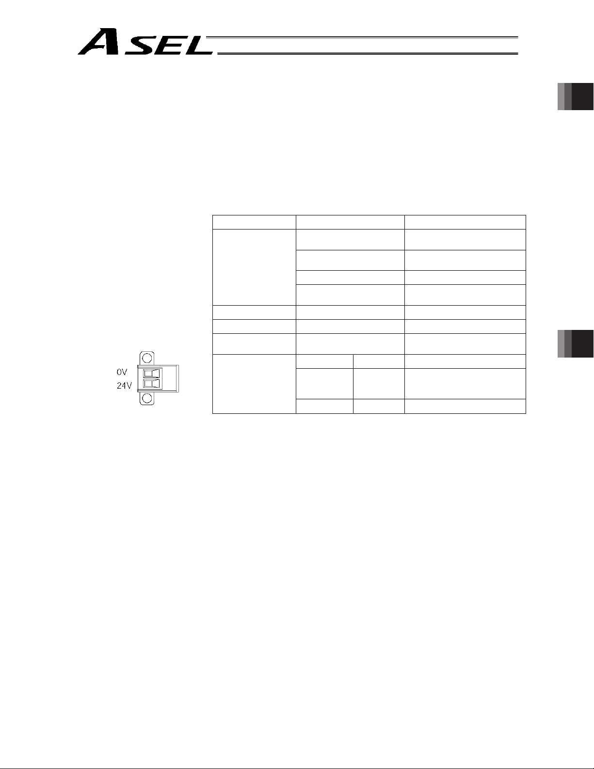
Part 1 Installation
[16] Motor power connector: This connector is used to input the 24-VDC motor power.
The power supply connected to this connector is used as the dedicated
motor drive source.
Since the controller has a built-in drive-source cutoff relay, the power
supply to the motor will be cut off internally if an emergency stop is
actuated or other abnormality occurs.
Although the motor power and control power are input independently, the
0-V terminals of both are connected inside the controller. They are also
connected to the ground for the controller’s internal power supply and are
not insulated.
Item Specification Remarks
5.08 mm, 2-piece
COMBICON, 2 pins
Applicable
connector
Connector name MP
Input voltage
Maximum input
current
Terminal
assignments
Cable-end connector
Applicable wire size AWG20 ~ 14 (0.5 ~ 2.0 sq)
Recommended stripped-
wire length
24 VDC r 10%
10.2 A 5.1 A per axis
No. Name Function
1 0V
2 24V Motor power input +24 V
MSTB2.5/2-GF-5.08 by
Phoenix Contact
MSTB2.5/2-STF-5.08 by
Phoenix Contact
7 mm
Motor power input ground
(Connected to the internal
ground)
Part 1 Installation Chapter 2 Specications
[17] Axis 1 absolute-data
backup battery
connector:
[18] Axis 2 absolute-data
backup battery
connector:
This connector is used to connect the absolute-data backup battery for
axis 1. (This connector is required only if your controller is of absoluteencoder specification.)
This connector is used to connect the absolute-data backup battery for
axis 2. (This connector is required only if your controller is of absoluteencoder specification.)
19
Page 42

Chapter 3 Installation and Wiring
1. External Dimensions
(1) 2-axis specification
Part 1 Installation
(The same external dimensions also apply to the 1-axis specification.)
43
5
110
Part 1 Installation
Chapter 3 Installation and Wiring
159
151
137
3
5
20
Page 43
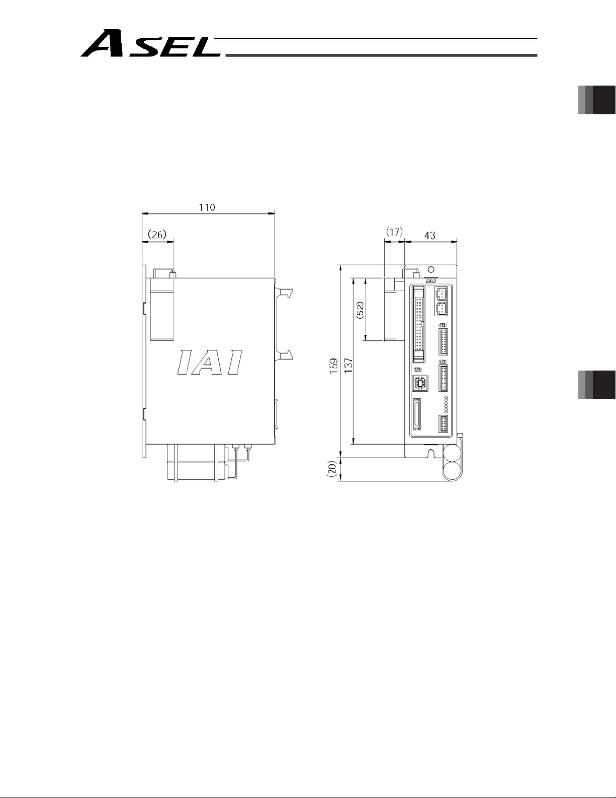
Part 1 Installation
(2) 2-axis specification with battery
Part 1 Installation
Chapter 3 Installation and Wiring
21
Page 44

As for the use environment, this product can be used in an environment of pollution degree 2
equivalent.
*1 Pollution degree 2: Normally only non-conductive pollutants exist, which are expected to be
temporarily conductive due to condensation. (EN60947-5-1)
2. Installation Environment
(1) When installing and wiring the controller, do not block the ventilation holes provided for cooling.
(Insufficient ventilation will not only prevent the product from functioning fully, but it may also result in
Part 1 Installation
failure.)
(2) Prevent foreign matter from entering the controller through the ventilation holes. Since the controller is
not designed as dustproof or waterproof (oilproof), avoid using it in a dusty place or place subject to
oil mist or splashed cutting fluid.
(3) Do not expose the controller to direct sunlight or radiant heat from a high heat source such as a heat-
treating furnace.
(4) Use the controller in a non-condensing environment free from corrosive or inflammable gases.
(5) Use the controller in an environment where it will not receive external vibration or impact.
(6) Prevent electrical noise from entering the controller or its cables.
Environmental Condition of Controller
Part 1 Installation
*1
or
Chapter 3 Installation and Wiring
Item Specification and description
Operating temperature range
0 ~ 40qC
Operating humidity range 10% ~ 95% (Non-condensing; conforming to JIS C3502 RH-2)
Storage temperature range
-25qC ~ 70qC (Excluding the battery)
Maximum operating altitude 2000 m
Protection class IP20
Vibration
Impact
10 d f < 57: 0.035 mm (continuous), 0.075 mm (intermittent)
57 d f d 150: 4.9 m/s
X, Y and Z directions
147 mm/s
2
, 11 ms, half-sine pulse, 3 times each in X, Y and Z
directions
2
(continuous), 9.8 m/s2 (intermittent)
22
Page 45

3. Heat Radiation and Installation
Part 1 Installation
Design the control panel size, controller layout and cooling method so that the ambient temperature
around the controller will be kept at or below 40°C.
Install the controller vertically on a wall, as illustrated below. The controller will be cooled by natural
convection. Be sure to install the controller in the aforementioned direction and provide a minimum
clearance of 50 mm above and below the controller.
If multiple controllers are to be installed side by side, providing additional suction fans on top of the
controllers will help maintain a uniform ambient temperature.
Provide a minimum clearance of 95 mm between the front side of the controller and a wall (enclosure).
Airflow direction
Fan
50 mm min.
95 mm min.
Part 1 Installation
50 mm min.
Airflow
If multiple controllers are to be connected on top of one another, prevent the controller above from
taking in the exhaust air from the controller below.
Chapter 3 Installation and Wiring
23
Page 46

Part 1 Installation
4. Noise Control Measures and Grounding
The ASEL controller has no dedicated terminal to connect the FG to ground. Accordingly, provide
grounding using the controller mounting screw.
[1] Provide dedicated Class D grounding. The grounding wire should have a size of 2.0 to
Part 1 Installation
[2] Notes on wiring method
Use twisted wires for the 24-VDC external power supply.
2
5.5 mm
or larger.
Controller
Other
equipment
Connect a cable of
the largest possible
size over the shortest
possible distance.
Metal
enclosure
Controller
Other
equipment
Class D grounding Proper grounding Avoid using this method.
Chapter 3 Installation and Wiring
Wire the controller cables separately from lines creating a strong electric field such as power circuit
lines (by not bundling them together or placing in the same cable duct).
If you wish to extend the motor cable or encoder cable beyond the length of each supplied cable,
please contact IAI’s Technical Service Section or Sales Engineering Section.
24
Page 47

Part 1 Installation
(3) Noise sources and noise elimination
There are many noise sources, but solenoid valves, magnet switches and relays are of particular
concern when building a system. Noise from these parts can be eliminated using the measures
specified below:
[1] AC solenoid valve, magnet switch, relay
Measure --- Install a surge killer in parallel with the coil.
Surge killer
m Point
Wire from each coil over the shortest distance.
Installing a surge killer on the terminal block, etc.,
will be less effective because of a longer distance
from the coil.
Part 1 Installation
[2] DC solenoid valve, magnet switch, relay
Measure --- Install a diode in parallel with the coil. Determine the diode capacity in accordance with
the load capacity.
In a DC circuit, connecting a diode in reversed polarity will
damage the diode, internal parts of the controller and DC
power supply. Exercise due caution.
Diode
The above noise elimination measures are particularly important when a 24-VDC relay is driven
directly by a controller output and there is also a 100-VAC solenoid valve, etc.
Chapter 3 Installation and Wiring
25
Page 48

Reference Circuit Diagram
Part 1 Installation
Part 1 Installation
Controller
Surge absorber
Chapter 3 Installation and Wiring
Solenoid valve
26
Page 49

5. Supply Voltage
Part 1 Installation
The supply voltage to the controller is 24 VDC r 10%.
The power-supply current varies depending on the number of axes, as shown below.
1-axis specification 2-axis specification
[1] Control power-supply current 1.2 A
[2] Rated motor power-input current 1.7 A 3.4 A
[3] Maximum motor power-input current 5.1 A 10.2 A
[4] Rated current ([1] + [2]) 2.9 A 4.6 A
[5] Maximum current ([1] + [3]) 6.3 A 11.4 A
Part 1 Installation
Chapter 3 Installation and Wiring
27
Page 50

Part 1 Installation
6. Wiring
6.1 Wiring the Control Power Supply, Emergency Stop Switch and Enable Switch
As shown to the left, insert the stripped end of each
cable into the control power & system I/O connector,
and tighten the screws with a screwdriver.
Part 1 Installation
Enable switch
Recommended cable size: 0.75 mm
Recommended stripped-wire length: 7 mm
Emergency stop switch
24 VDC
2
(AWG18)
Chapter 3 Installation and Wiring
28
Page 51

6.2 Wiring the Motor Power Cables
Part 1 Installation
As shown to the left, insert the stripped end of each
cable into the motor power connector, and tighten the
screws with a screwdriver.
2
Recommended cable size: 2 mm
(AWG14)
Recommended stripped-wire length: 7 mm
As shown to the left, tighten the screws to affix the
connector.
Part 1 Installation
24 VDC
Chapter 3 Installation and Wiring
29
Page 52

6.3 Connecting the Actuator
6.3.1 Connecting the Motor Cable (M1/M2)
Part 1 Installation
6.3.2 Connecting the Encoder Cable (PG1/PG2)
Part 1 Installation
Connect the motor cable from the actuator to the
applicable motor connector on the front face of the
controller.
Chapter 3 Installation and Wiring
Connect the encoder cable from the actuator to the
applicable encoder connector on the front face of the
controller.
Caution: With the absolute specification,
disconnect the absolute-data
backup battery connector before
connecting the encoder cable.
Connect the absolute-data
backup battery connector after
turning on the main power.
30
Page 53
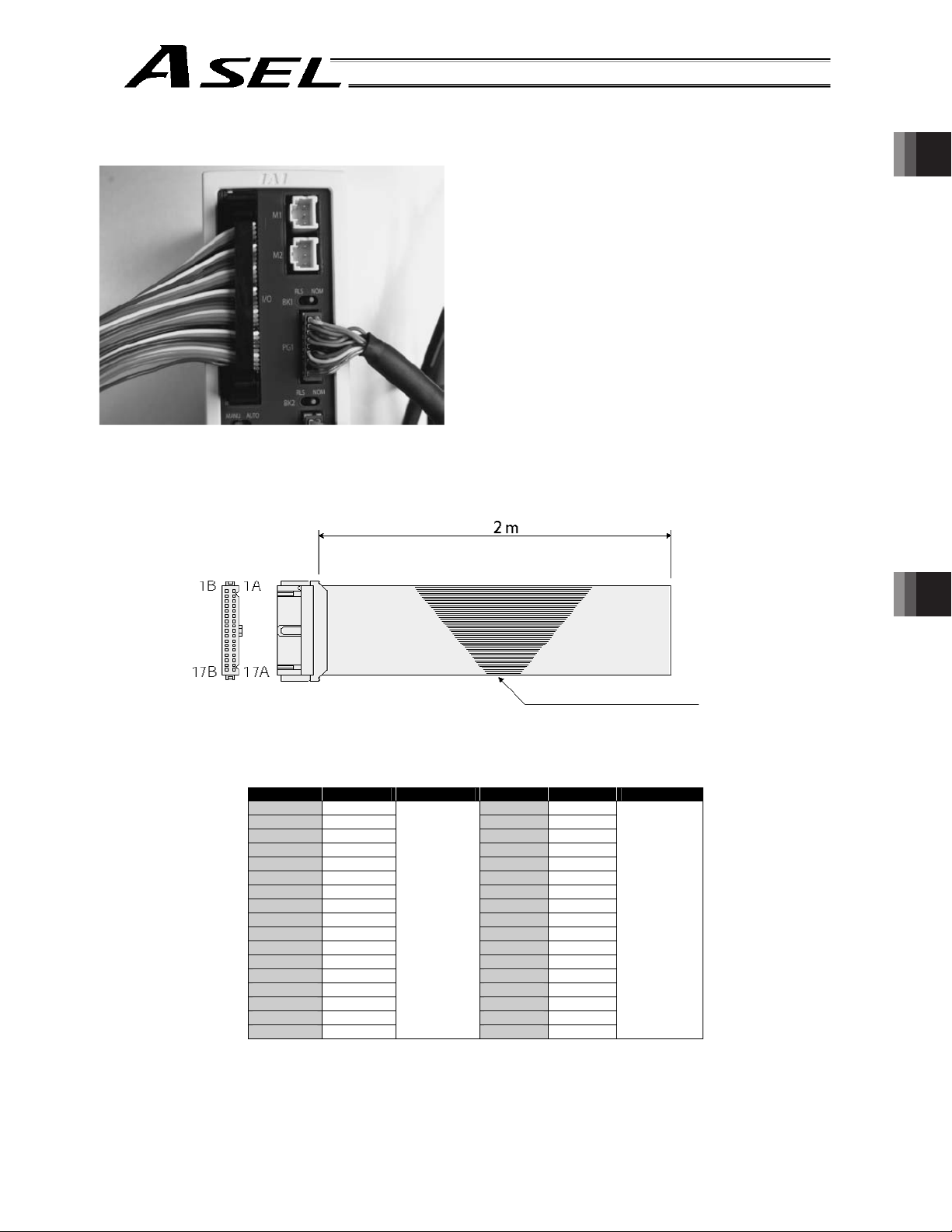
6.4 Connecting the PIO Cable (I/O)
Part 1 Installation
I/O flat cable (supplied): Model CB-DS-P10020
Connect the supplied flat cable. Connect the opposite
end (open end without connector) of the cable to a
desired peripheral (host PLC, etc.).
No connector
Part 1 Installation
Chapter 3 Installation and Wiring
Flat cable (34 cores)
No. Color Wire No. Color Wire
1A Brown 1 9B Gray 2
1B Red 1 10A White 2
2A Orange 1 10B Black 2
2B Yellow 1 11A Brown-3
3A Green 1 11B Red 3
3B Blue 1 12A Orange 3
4A Purple 1 12B Yellow 3
4B Gray 1 13A Green 3
5A White 1 13B Blue 3
5B Black 1 14A Purple 3
6A Brown-2 14B Gray 3
6B Red 2 15A White 3
7A Orange 2 15B Black 3
7B Yellow 2 16A Brown-4
8A Green 2 16B Red 4
8B Blue 2 17A Orange 4
9A Purple 2
Flat cable,
pressure-
welded
Flat cable,
pressure-
welded
17B Yellow 4
31
Page 54

6.4.1 I/O Connection Diagram
(1) NPN specification (Program mode)
Part 1 Installation
Part 1 Installation
Pin No.
Category
Input
Port No. Function Cable color
External power supply 24 V
Program specification (PRG No. 1)
Program specification (PRG No. 2)
Program specification (PRG No. 4)
Program specification (PRG No. 8)
Program specification (PRG No. 10)
Program specification (PRG No. 20)
Program specification (PRG No. 40)
Software reset (restart)
Program start
General-purpose input
General-purpose input
General-purpose input
General-purpose input
General-purpose input
General-purpose input
General-purpose input
General-purpose input
General-purpose input
General-purpose input
General-purpose input
General-purpose input
General-purpose input
General-purpose input
General-purpose input
1 - Brown
1 - Red
1 - Orange
1 - Yellow
1 - Green
1 - Blue
1 - Purple
1 - Gray
1 - White
1 - Black
2 - Brown
2 - Red
2 - Orange
2 - Yellow
2 - Green
2 - Blue
2 - Purple
2 - Gray
2 - White
2 - Black
3 - Brown
3 - Red
3 - Orange
3 - Yellow
3 - Green
Chapter 3 Installation and Wiring
32
Pin No.
Category
Port No.
Alarm output
Ready output
General-purpose output
Output
General-purpose output
General-purpose output
General-purpose output
General-purpose output
General-purpose output
External power supply 0 V
The above functions reflect the factory settings.
Function
Cable color
3 - Blue
3 - Purple
3 - Gray
3 - White
3 - Black
4 - Brown
4 - Red
4 - Orange
4 - Yellow
Page 55
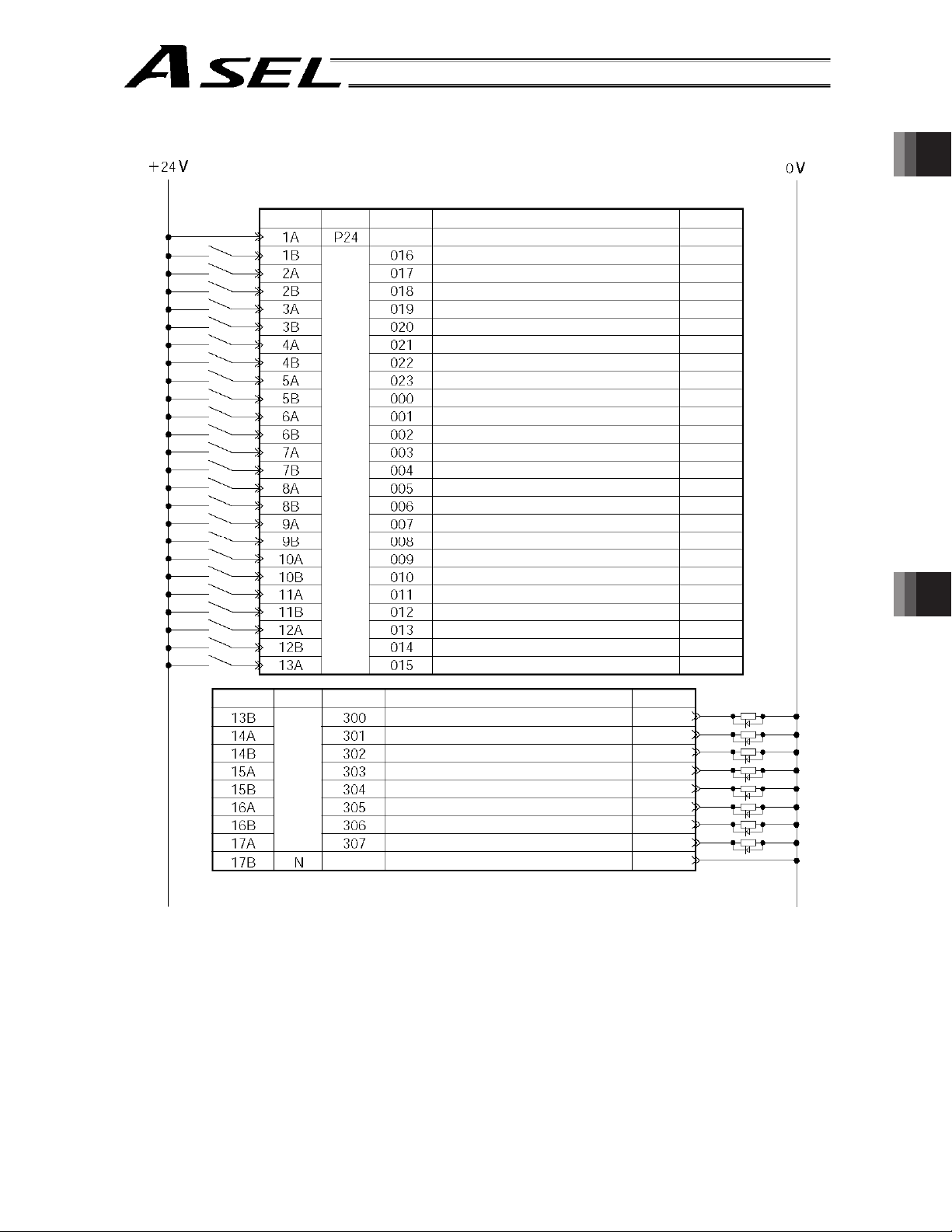
(2) PNP specification (Program mode)
Part 1 Installation
Part 1 Installation
Pin No.
Category
Input
Port No. Function Cable color
External power supply 24 V
Program specification (PRG No. 1)
Program specification (PRG No. 2)
Program specification (PRG No. 4)
Program specification (PRG No. 8)
Program specification (PRG No. 10)
Program specification (PRG No. 20)
Program specification (PRG No. 40)
Software reset (restart)
Program start
General-purpose input
General-purpose input
General-purpose input
General-purpose input
General-purpose input
General-purpose input
General-purpose input
General-purpose input
General-purpose input
General-purpose input
General-purpose input
General-purpose input
General-purpose input
General-purpose input
General-purpose input
1 - Brown
1 - Red
1 - Orange
1 - Yellow
1 - Green
1 - Blue
1 - Purple
1 - Gray
1 - White
1 - Black
2 - Brown
2 - Red
2 - Orange
2 - Yellow
2 - Green
2 - Blue
2 - Purple
2 - Gray
2 - White
2 - Black
3 - Brown
3 - Red
3 - Orange
3 - Yellow
3 - Green
Chapter 3 Installation and Wiring
Pin No.
Category
Port No. Function Cable color
Alarm output
Ready output
General-purpose output
Output
General-purpose output
General-purpose output
General-purpose output
General-purpose output
General-purpose output
External power supply 0 V
The above functions reflect the factory settings.
3 - Blue
3 - Purple
3 - Gray
3 - White
3 - Black
4 - Brown
4 - Red
4 - Orange
4 - Yellow
33
Page 56

(3) NPN specification (Positioner mode)
Part 1 Installation
Part 1 Installation
Pin No.
Category
Input
Port No.
Standard mode
Position input 10
Position input 11
Position input 12
Position input 13
Error reset
Start
Home return
Servo ON
Push motion
*Pause
*Cancellation
Interpolation
Position input 1
Position input 2
Position input 3
Position input 4
Position input 5
Position input 6
Position input 7
Position input 8
Position input 9
Product switching mode
Input 10
Input 11
Input 12
Input 13
Input 14
Input 15
Input 16
Error reset
Start
Home return
Servo ON
Push motion
*Pause
*Cancellation
Interpolation
Input 1
Input 2
Input 3
Input 4
Input 5
Input 6
Input 7
Input 8
Input 9
Positioner mode
2-axis independent
mode
24-V input
Position input 7
Position input 8
Position input 9
Position input 10
Position input 11
Position input 12
Position input 13
Error reset
Axis 1 start
Home return
Axis 1 servo ON
*Axis 1 pause
*Axis 1 cancellation
Axis 2 start
Axis 2 home return
Axis 2 servo ON
*Axis 2 pause
*Axis 2 cancellation
Position input 1
Position input 2
Position input 3
Position input 4
Position input 5
Position input 6
Teaching mode
Axis 1 jog-
Axis 2 jog+
Axis 2 jog-
Inching (0.01 mm)
Inching (0.1 mm)
Inching (0.5 mm)
Inching (1 mm)
Error reset
Start
Sarvo ON
*Pause
Position input 1
Position input 2
Position input 3
Position input 4
Position input 5
Position input 6
Position input 7
Position input 8
Position input 9
Position input 10
Position input 11
Teaching mode
specification
Axis 1 jog+
DC-S-C1 compatible
mode
Position No. 1000 input
CPU reset
Start
Pause
Cancellation
Interpolation setting
Position No. 1 input
Position No. 2 input
Position No. 4 input
Position No. 8 input
Position No. 10 input
Position No. 20 input
Position No. 40 input
Position No. 80 input
Position No. 100 input
Position No. 200 input
Position No. 400 input
Position No. 800 input
Cable
color
1 - Brown
1 - Red
1 - Orange
1 - Yellow
1 - Green
1 - Blue
1 - Purple
1 - Gray
1 - White
1 - Black
2 - Brown
2 - Red
2 - Orange
2 - Yellow
2 - Green
2 - Blue
2 - Purple
2 - Gray
2 - White
2 - Black
3 - Brown
3 - Red
3 - Orange
3 - Yellow
3 - Green
Chapter 3 Installation and Wiring
34
Pin No.
Category
Output
Port No.
Standard mode
*Alarm
Ready
Positioning complete
Home return complete
Servo ON output
Push motion complete
System battery error
Absolute battery error
Product switching mode
*Alarm
Ready
Positioning complete
Home return complete
Servo ON output
Push motion complete
System battery error
Absolute battery error
Positioner mode
2-axis independent
mode
*Alarm
Ready
Axis 1 positioning
complete
Axis 1 home return
complete
Axis 1 servo ON
Axis 2 positioning
complete
Axis 2 home return
complete
Axis 2 servo ON
0-V input
Teaching mode
*Alarm
Ready
Positioning complete
Home return complete
Servo ON output
System battery error
Absolute battery error
DC-S-C1 compatible
mode
*Alarm
Ready
Positioning complete
System battery error
Absolute battery error
Cable
3 - Blue
3 - Purple
3 - Gray
3 - White
3 - Black
4 - Brown
4 - Red
4 - Orange
4 - Yellow
*: Contact B (Always ON)
color
Page 57

(4) PNP specification (Positioner mode)
Part 1 Installation
Part 1 Installation
Pin No.
Category
Input
Port No.
Standard mode
Position input 10
Position input 11
Position input 12
Position input 13
Error reset
Start
Home return
Servo ON
Push motion
*Pause
*Cancellation
Interpolation
Position input 1
Position input 2
Position input 3
Position input 4
Position input 5
Position input 6
Position input 7
Position input 8
Position input 9
Product switching mode
Input 10
Input 11
Input 12
Input 13
Input 14
Input 15
Input 16
Error reset
Start
Home return
Servo ON
Push motion
*Pause
*Cancellation
Interpolation
Input 1
Input 2
Input 3
Input 4
Input 5
Input 6
Input 7
Input 8
Input 9
Positioner mode
2-axis independent
mode
24-V input
Position input 7
Position input 8
Position input 9
Position input 10
Position input 11
Position input 12
Position input 13
Error reset
Axis 1 start
Home return
Axis 1 servo ON
*Axis 1 pause
*Axis 1 cancellation
Axis 2 start
Axis 2 home return
Axis 2 servo ON
*Axis 2 pause
*Axis 2 cancellation
Position input 1
Position input 2
Position input 3
Position input 4
Position input 5
Position input 6
Teaching mode
Axis 1 jog-
Axis 2 jog+
Axis 2 jog-
Inching (0.01 mm)
Inching (0.1 mm)
Inching (0.5 mm)
Inching (1 mm)
Error reset
Start
Sarvo ON
*Pause
Position input 1
Position input 2
Position input 3
Position input 4
Position input 5
Position input 6
Position input 7
Position input 8
Position input 9
Position input 10
Position input 11
Teaching mode
specification
Axis 1 jog+
DC-S-C1 compatible
mode
Position No. 1000 input
CPU reset
Start
Pause
Cancellation
Interpolation setting
Position No. 1 input
Position No. 2 input
Position No. 4 input
Position No. 8 input
Position No. 10 input
Position No. 20 input
Position No. 40 input
Position No. 80 input
Position No. 100 input
Position No. 200 input
Position No. 400 input
Position No. 800 input
Cable
color
1 - Brown
1 - Red
1 - Orange
1 - Yellow
1 - Green
1 - Blue
1 - Purple
1 - Gray
1 - White
1 - Black
2 - Brown
2 - Red
2 - Orange
2 - Yellow
2 - Green
2 - Blue
2 - Purple
2 - Gray
2 - White
2 - Black
3 - Brown
3 - Red
3 - Orange
3 - Yellow
3 - Green
Chapter 3 Installation and Wiring
Pin No.
Category
Output
Port No.
Standard mode
*Alarm
Ready
Positioning complete
Home return complete
Servo ON output
Push motion complete
System battery error
Absolute battery error
Product switching mode
*Alarm
Ready
Positioning complete
Home return complete
Servo ON output
Push motion complete
System battery error
Absolute battery error
Positioner mode
2-axis independent
mode
*Alarm
Ready
Axis 1 positioning
complete
Axis 1 home return
complete
Axis 1 servo ON
Axis 2 positioning
complete
Axis 2 home return
complete
Axis 2 servo ON
0-V input
Teaching mode
*Alarm
Ready
Positioning complete
Home return complete
Servo ON output
System battery error
Absolute battery error
DC-S-C1 compatible
mode
*Alarm
Ready
Positioning complete
System battery error
Absolute battery error
Cable
3 - Blue
3 - Purple
3 - Gray
3 - White
3 - Black
4 - Brown
4 - Red
4 - Orange
4 - Yellow
*: Contact B (Always ON)
color
35
Page 58

6.5 External I/O Specifications
6.5.1 NPN Specification
(1) Input part
Part 1 Installation
External Input Specifications (NPN Specification)
Item Specification
Input voltage
Input current 7 mA per circuit
ON/OFF voltage
Insulation method Photocoupler insulation
External devices
24 VDC r10%
ON voltage --- 16.0 VDC min.
OFF voltage --- 5.0 VDC max.
[1] No-voltage contact (minimum load of approx. 5 VDC/1 mA)
[2] Photoelectric/proximity sensor (NPN type)
[3] Sequencer transistor output (open-collector type)
[4] Sequencer contact output (minimum load of approx. 5 VDC/1 mA)
Part 1 Installation
Chapter 3 Installation and Wiring
[Input circuit]
560 :
P24*
+
External power
supply 24 VDC 10%
-
Internal circuit
3.3 K:
Input terminal
* P24: I/O interface pin No. 1
Caution
If a non-contact circuit is connected externally, malfunction may result from leakage
current. Use a circuit in which leakage current in a switch-off state does not exceed 1
mA.
ASEL controller’s input signal
ON duration
At the default settings, the system recognizes the ON/OFF durations of input signals if they
are approx. 4 msec or longer. The ON/OFF duration settings can also be changed using I/O
parameter No. 20 (input filtering frequency).
36
OFF duration
Page 59

(2) Output part
Part 1 Installation
External Output Specifications (NPN Specification)
Item Specification
Load voltage 24 VDC
Maximum load current 100 mA per point, 400 mA per 8 ports Note)
Leakage current 0.1 mA max. per point
Insulation method Photocoupler insulation
External devices
Note) 400 mA is the maximum total load current of output port Nos. 300 to 307.
[1] Miniature relay
[2] Sequencer input unit
TD62084 (or equivalent)
[Output circuit]
P24*
Surge absorber
Load
Internal circuit
Output terminal
Part 1 Installation
Chapter 3 Installation and Wiring
External power supply
24 VDC r 10%
N*
* P24: I/O interface pin No. 1A
* N: I/O interface pin No. 17B
Caution
In the event that the load is short-circuited or current exceeding the maximum load
current is input, the overcurrent protection circuit will be actuated to cut off the circuit.
However, give due consideration to the circuit connection layout to prevent short-circuit
or overcurrent.
37
Page 60

6.5.2 PNP Specification
(1) Input part
Part 1 Installation
External Input Specifications (PNP Specification)
Item Specification
Input voltage
Input current 7 mA per circuit
ON/OFF voltage
Insulation method Photocoupler insulation
External devices
24 VDC r10%
ON voltage --- 8 VDC max.
OFF voltage --- 19 VDC min.
[1] No-voltage contact (minimum load of approx. 5 VDC/1 mA)
[2] Photoelectric/proximity sensor (PNP type)
[3] Sequencer transistor output (open-collector type)
[4] Sequencer contact output (minimum load of approx. 5 VDC/1 mA)
[Input circuit]
Input terminal
Part 1 Installation
Chapter 3 Installation and Wiring
+
External power
560 :
supply 24 VDC 10%
-
Internal circuit
:
3.3 K
N*
* N: I/O interface pin No. 17B
Caution
If a non-contact circuit is connected externally, malfunction may result from leakage
current. Use a circuit in which leakage current in a switch-off state does not exceed 1
mA.
ASEL controller’s input signal
ON duration
OFF duration
38
At the default settings, the system recognizes the ON/OFF durations of input signals if they
are approx. 4 msec or longer. The ON/OFF duration settings can also be changed using I/O
parameter No. 20 (input filtering frequency).
Page 61

(2) Output part
Part 1 Installation
External Output Specifications (PNP specification)
Item Specification
Load voltage 24 VDC
Maximum load current 100 mA per point, 400 mA per 8 ports Note)
Leakage current 0.1 mA max. per point
Insulation method Photocoupler insulation
External devices
Note) 400 mA is the maximum total load current of output port Nos. 300 to 307.
[1] Miniature relay
[2] Sequencer input unit
TD62784 (or equivalent)
[Output circuit]
P24
Surge absorber
10 :
Part 1 Installation
Internal circuit
Output terminal
Load
N
+
External power supply
24 VDC 10%
-
* P24: I/O interface pin No. 1A
* N: I/O interface pin No. 17B
Caution
In the event that the load is short-circuited or a current exceeding the maximum load
current is input, the overcurrent protection circuit will be actuated to cut off the circuit.
However, give due consideration to the circuit connection layout to prevent short-circuit
or overcurrent.
Chapter 3 Installation and Wiring
39
Page 62

6.6 Connecting the Teaching Pendant/PC (Software) (TP) (Optional)
Part 1 Installation
6.7 Connecting the Panel Unit (Optional)
Part 1 Installation
The ASEL controller’s teaching connector (TP) is a
small, half-pitch connector. If you are using a teaching
pendant or PC software cable, connect the cable to a
connector conversion cable, and then connect the
conversion cable to the teaching connector on the
controller.
When the optional panel unit is connected, the
controller status (program number of each active
program, error codes, etc.) can be monitored.
Chapter 3 Installation and Wiring
40
Page 63

Part 1 Installation
6.7.1 Explanation of Codes Displayed on the Panel Unit (Optional)
(1) Application
Display Priority (*1) Description
1 Control power cut off
1 System-down level error
2 Writing data to the flash ROM.
3 Emergency stop is being actuated (except during the update mode).
4 Enable switch (deadman switch/safety gate) OFF (except in the update mode)
5 Cold-start level error
5 Cold-start level error
5 Operation-cancellation level error
Part 1 Installation
5 Operation-cancellation level error
6 Waiting for a drive-source cutoff reset input (except during the update mode).
6 Operation is in pause (waiting for restart) (except during the update mode).
7 All servo axes are interlocked (except during the update mode).
8 Message level error
8 Message level error
9 Core update mode
9 Core update is in progress.
9 Core update has completed.
9 Slave update mode
9 Slave update is in progress.
9 Slave update has completed.
9 Running a program (last started program); “No.” indicates program number.
Chapter 3 Installation and Wiring
9 Initialization sequence number
9 Debug mode
(*1) The priority increases as the number decreases.
41
Page 64
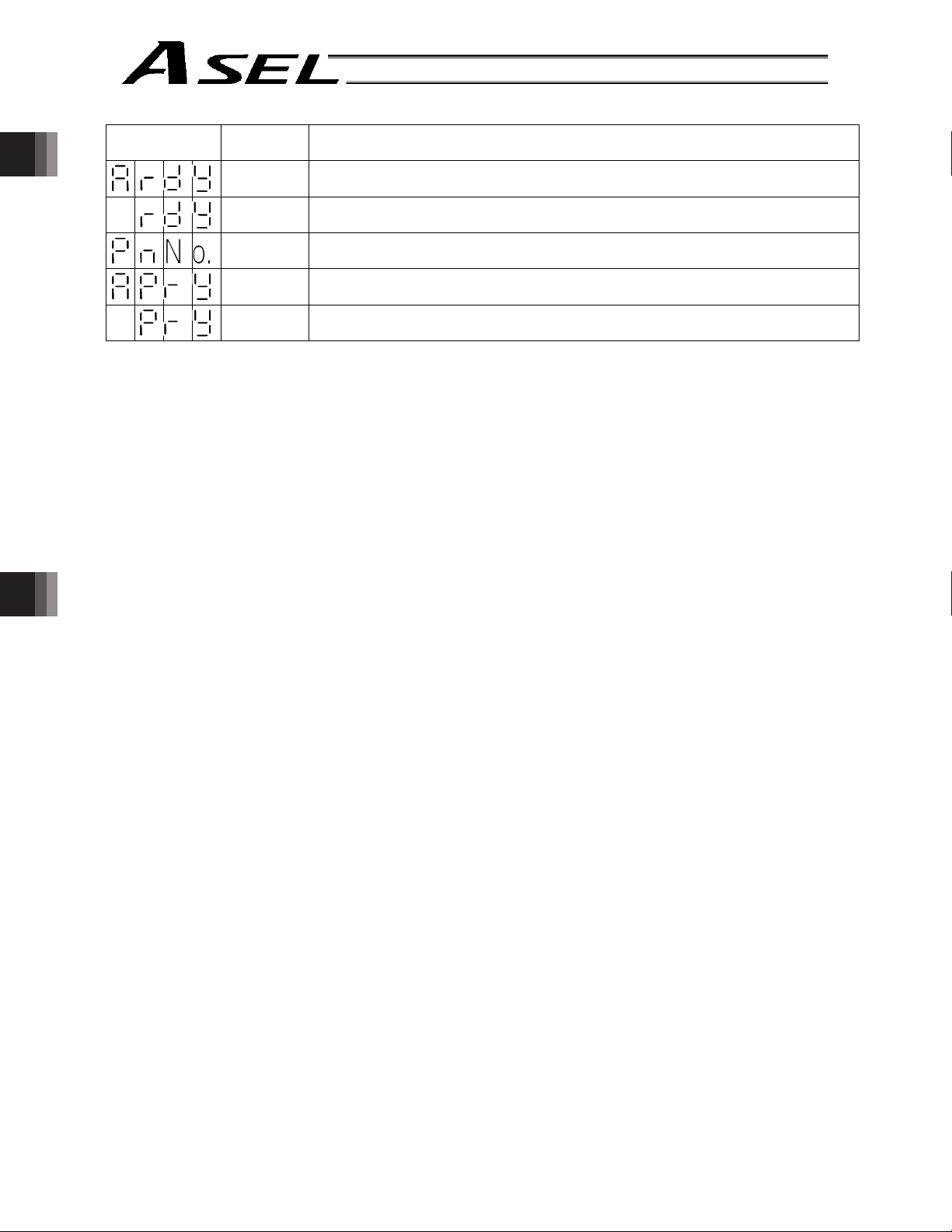
Part 1 Installation
Display Priority (*1) Description
9 Ready status (auto mode) (Program mode)
9 Ready status (manual mode) (Program mode)
9 Operating in positioner mode; “No.” indicates positioner mode number.
9 Ready status (auto mode) (Positioner mode)
Part 1 Installation
9 Ready status (manual mode) (Positioner mode)
(*1) The priority increases as the number decreases.
Chapter 3 Installation and Wiring
42
Page 65

(2) Core
Part 1 Installation
Display Priority (*1) Description
1 Control power cut off
1 Cold-start level error
1 Cold-start level error
1 Operation-cancellation level error
1 Operation-cancellation level error
2 Message level error
2 Message level error
2 Application update mode
2 Application update is in progress.
2 Application update has completed.
2 Hardware test mode process
2 Clearing the application flash ROM.
2 Application flash ROM has been cleared.
Part 1 Installation
Chapter 3 Installation and Wiring
2 Jump to the application
2 Core flash-ROM check process
2 Application flash-ROM check process
2 SDRAM check process
(*1) The priority increases as the number decreases.
43
Page 66

6.7.2 Current Monitor and Variable Monitor
By setting other parameter Nos. 49 and 50 appropriately, the optional panel unit can be used to monitor
either current levels or variables.
(1) Current monitor
Currents of up to four axes having continuous axis numbers can be monitored.
Parameter settings
Other parameter No. 49 = 1
Other parameter No. 50 = Smallest axis number among the axes to be monitored
Part 1 Installation
Example) If other parameter No. 49 is set to “1” and other parameter No. 50 to “1” for a 2-axis controller,
Part 1 Installation
the far-right segment digit will show the current for axis 1.
Axis 2 Axis 1
Chapter 3 Installation and Wiring
When data is written to the flash ROM or a software reset (restart) is executed after the parameter values
have been input, the panel window will show the motor current to rating ratio (%) by a segment pattern,
instead of “ready status” or “program run number.”
The segment display patterns and corresponding motor current to rating ratios (%) are shown below.
0 < Motor current to rating ratio (%) d 25
25 < Motor current to rating ratio (%) d 50
50 < Motor current to rating ratio (%)
75 < Motor current to rating ratio (%)
d 75
d 100
100 < Motor current to rating ratio (%) d 150
150 < Motor current to rating ratio (%) d 200
200 < Motor current to rating ratio (%)
Thick lines indicate illuminated segments.
44
Page 67

Part 1 Installation
(2) Variable monitor
The contents of global integer variables can be displayed on the panel window.
Positive integers of 1 to 999 can be displayed.
Parameter settings
Other parameter No. 49 = 2
Other parameter No. 50 = Variable number of the global integer variable to be monitored
When data is written to the flash ROM or a software reset (restart) is executed after the parameter values
have been input, the panel window will show the content of the global integer variable, instead of “ready
status” or “program run number.” The far-left segment digit should read “U.”
Display example)
Part 1 Installation
Chapter 3 Installation and Wiring
45
Page 68

6.8 Installation Method for the Absolute-Data Backup Battery
The ASEL controller does not come with a holder or any other dedicated piece for installing the absolutedata backup battery. The user must affix the battery using tie-bands.
Example of installation
Part 1 Installation
Part 1 Installation
As shown to the left, guide tie-bands through the
controller and tie the ends to make loose loops.
Guide the batteries into the tie-band loops.
Tighten the tie-bands and cut off any excess length at
the end.
Chapter 3 Installation and Wiring
Connect each battery connector.
Pay attention to the connector orientation.
(The connector hook should face the left side when
viewed from the front of the controller.)
Caution: If the main power cannot be turned
on immediately after the encoder
cable has been connected, do not
connect the battery connector.
46
Page 69

6.9 Installing the System-Memory Backup Battery (Optional)
Part 1 Installation
As shown to the left, install the supplied battery
holder on the left side face of the controller.
Insert the battery into the holder.
Connect the battery connector.
Pay attention to the connector orientation.
(The connector hook should face the right side.)
Part 1 Installation
Chapter 3 Installation and Wiring
47
Page 70

Chapter 4 Operation
1. Startup
(1) Connect the motor cable and encoder cable to the controller.
(2) Connect the PIO connector to the host PLC using the supplied flat cable.
(3) Execute an emergency stop.
(4) Connect the PC or teaching pendant.
Set the AUTO/MANU switch to the “MANU” side.
(5) Supply the 24-V PIO power through the flat cable.
Part 1 Installation
(6) Turn on the control power and motor power at the same time. (They should be taken from the same
power supply.
(7) Reset the emergency stop.
The EMG lamp turns off.
If the ALM lamp is lit, an error is present. Check the error list to identify the problem.
If the 24-V PIO power is not supplied, an “E69” error will generate.
If your controller is of absolute specification, a “914” or “CA2” error may generate during the startup,
indicating that an absolute reset must be performed. Refer to “How to Perform Absolute Reset.”
To check for errors, connect the teaching pendant, PC software or panel unit.
Part 1 Installation
Chapter 4 Operationg
48
Page 71
Part 1 Installation
1.1 Power ON Sequence
x Although separate inputs are provided for the control power and motor power, they should be supplied
from the same power-supply terminal.
x Turn on the PIO power first. You can turn on the PIO power much earlier than the control power and
motor power, as long as it is turned on before the control power/motor power.
The PIO power must be turned on
Taken from the
same power supply.
before the control power, in order
to perform checks during
initialization and self-diagnosis and
apply a hardware latch upon
detection of an error.
Part 1 Installation
Control power
Motor power
Controller status
PIO power
Must be turned
on first, as a
rule.
Must be turned on
simultaneously, as a rule.
Initialization/self-diagnosis
Normal operating condition
* If the PIO power is not turned on before the control power is turned on, an error will be detected.
1.2 Power Cutoff Sequence
x If the PIO power is turned off before the control power and motor power (before the power cutoff
processing is performed), a PIO power error may be logged internally by the controller.
x The PIO power can be turned off much later than the control power and motor power, as long as it is
turned off after the control power/motor power.
Once the control power
drops to approx. 19 V or
below, the power cutoff
Control power
Motor power
Must be turned off
simultaneously, as a rule.
processing is started.
Chapter 4 Operation
Controller status
PIO power
If the PIO power is
turned off during this
period, an error may
be logged internally by
the controller.
Power cutoff processing
49
Page 72

Part 1 Installation
2. How to Perform Absolute Reset (Absolute Specification)
If the ASEL controller experiences any abnormal absolute-encoder battery voltage or the battery or
encoder cable is disconnected, an encoder battery error will generate. In this case, you must perform an
absolute reset.
This chapter explains how to perform an absolute reset using the PC software. For the procedure to
perform an absolute reset from the teaching pendant, refer to the operation manual for your teaching
pendant.
Part 1 Installation
2.1 Preparation
PC
(1)
PC in which IAI’s X-SEL PC software (X_SEL.exe) has been installed
(2) PC cable (supplied with the PC software)
RS232C cross cable (fitted with a female 9-pin connector on the PC end and a male 25-pin connector
on the controller end)
+Connector conversion cable
Alternatively, use a USB cable and a dummy plug (optional).
(3) All adjustment items other than absolute reset must have been completed.
2.2 Procedure
(1) Turn off the ASEL controller power. Turn on the PC power and wait for the OS to start.
(2) Connect the 9-pin D-sub connector on the PC cable to the communication port on the PC, and
connect the 25-pin D-sub connector to the teaching connector on the controller.
Alternatively, connect the PC and controller using a USB cable. If the USB port is used, a dummy
plug must be connected to the teaching connector.
(3) Turn on the controller power. An encoder battery error will generate. If no other adjustment item is
outstanding, “ECA2” or “E914” should be displayed on the 7-segment LED. This indicates that the
controller has detected the encoder battery error.
(4) Launch the X-SEL PC software (X_SEL.exe) on the PC. The following steps explain the operating
Chapter 4 Operationg
procedures in the X-SEL PC software.
(5) When the Connection Check dialog box appears, set the communication port you are using on your
PC. Click OK. (The baud rate need not be set. The software will automatically detect and set the
baud rate.)
50
Page 73

(6) The main window of the X-SEL PC software opens.
Click OK to close the error message.
Part 1 Installation
Part 1 Installation
(7) From the M
onitor menu, select Error Detail to check the condition of the present error.
If the controller is experiencing an encoder battery error, the displayed window should look like the
one shown below (an absolute encoder is used for axis 2 in this example). After checking the error
detail, close the Error Detail window.
Chapter 4 Operation
51
Page 74
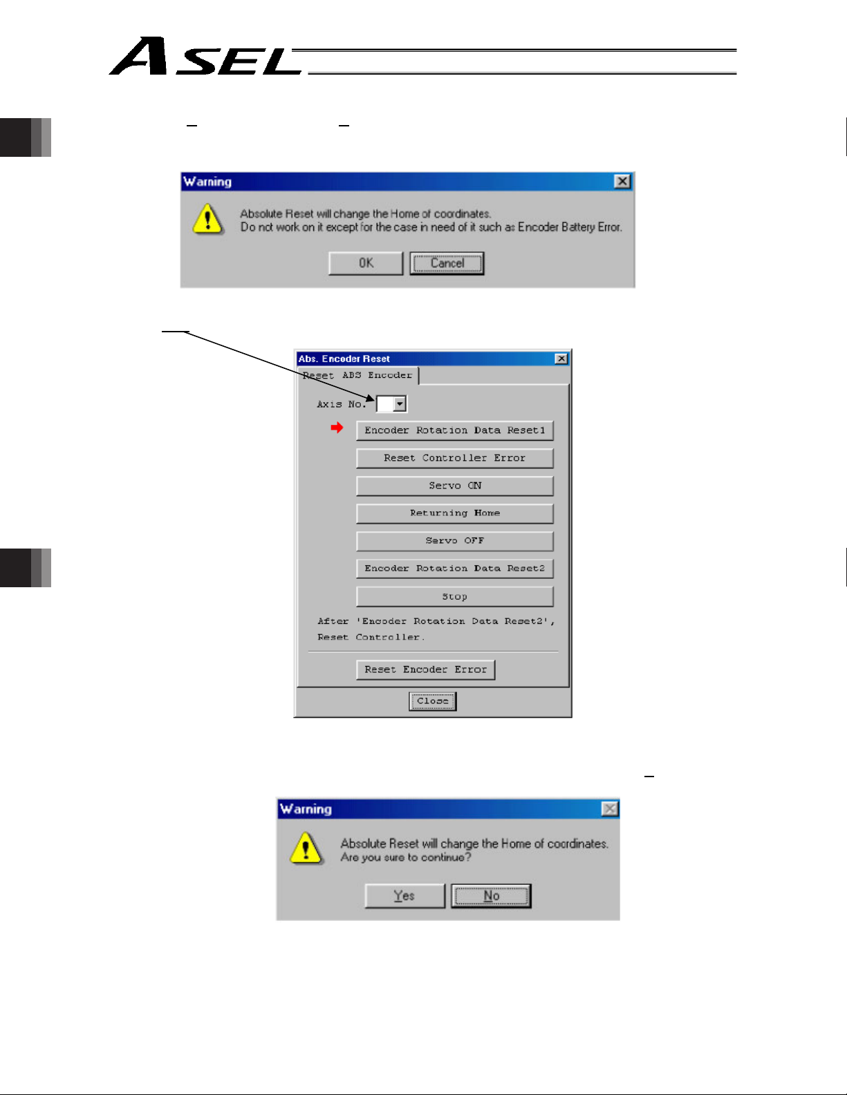
Part 1 Installation
(8) From the C
(9) When the Warning dialog box appears, click OK.
Part 1 Installation
(10) The Absolute Reset dialog box appears.
Click here
ontroller menu, select Absolute Reset.
to select the axis you want to perform an absolute reset for.
1
Chapter 4 Operationg
(11) Click Encoder Rotation Data Reset 1. When the Warning dialog box appears, click Y
52
es.
Page 75

Part 1 Installation
(12) Another Warning dialog box is displayed. Click Y
es again.
(13) After the controller has finished processing encoder rotation data reset 1, the red arrow will move to
the next item. Click the following processing buttons in this order (the arrow will move to the next one
after each processing is completed):
1. Controller Error Reset
2. Servo ON
3. Home Return
4. Servo OFF
Encoder rotation data reset 2 is performed with the servo turned on. Accordingly, the Servo
OFF step will be skipped.
5. Encoder Rotation Data Reset 2
After you have clicked Encoder Rotation Data Reset 2 and the processing is finished, the red arrow
will return to the position in shown in (10). To perform an absolute encoder reset for another axis,
select the target axis and perform the steps from (10) again. To end the procedure, click Close to
close the Absolute Reset dialog box.
(Note) If you have encountered a situation where an absolute encoder reset is required for two or
more axes, be sure to repeat steps (10) to (13) for all applicable axes before performing the
software reset in step (14) below.
Part 1 Installation
Chapter 4 Operation
53
Page 76

Part 1 Installation
(14) When the Confirmation dialog box appears, click Y
Part 1 Installation
(Note) If you continue to operate the controller without resetting the software or reconnecting the
(15) If an optional panel unit is connected and no other error is present, “rdy” (when the controller is in the
program mode) or “Pry” (in the positioner mode) should be displayed on the 7-seg LED.
(16) This completes the absolute reset.
To repeat the absolute reset, close the X-SEL PC software and perform the steps from the beginning.
es to restart the controller.
power, the following errors may generate:
Error No. C70: ABS coordinate non-confirmation error
Error No. C6F: Home-return incomplete error
Chapter 4 Operationg
54
Page 77

3. How to Start a Program
Part 1 Installation
With the ASEL Controller, the stored programs can be started (run) using four methods. Of these methods,
two are mainly used to debug programs or perform trial operations, while the remaining two are used in
general applications on site.
The former two methods are “starting from the teaching pendant” and “starting from the PC software.”
These methods provide simple means of checking the operation. For details on “starting from the teaching
pendant,” read the operation manual for the optional teaching pendant. For “starting from the PC
software,” read the applicable explanation in the manual supplied with the PC software.
The latter two methods are “starting automatically via parameter setting” and “starting via external signal
selection.” This chapter only explains the methods for “starting automatically via parameter setting” and
“starting via external signal selection.”
Starting via
Teaching pendant
ASEL
Controller
external signal
selection
Part 1 Installation
PC software
Start
Start
Starting
automatically via
parameter setting
Start
Chapter 4 Operation
55
Page 78

3.1 Starting a Program by Auto-Start via Parameter Setting
Other parameter No. 7 (Auto program start setting) = 1 (Standard factory setting)
This parameter is set using the teaching pendant or PC software.
Part 1 Installation
Part 1 Installation
Set an auto-start program number
Automatically starting the program
Caution
[Note on starting a program by auto-start]
The automatic operation will begin immediately after the controller is reset, so the user may be surprised
by unexpected movements of the equipment, particularly those caused by a sudden activation of the servo
actuator. To ensure safety, always provide an interlocking function, such as allowing the program
execution to proceed only after receiving a confirmation signal at the beginning of the program.
Chapter 4 Operationg
If you wish to start multiple programs at the same time, write multiple “EXPG” commands at the beginning
of the main program to start the remaining programs. Provide safety measures for each program to be
started.
Reset the controller
Set the number of the program you wish to start
automatically in other parameter No. 1 (auto-start
program number).
Set the controller mode to AUTO.
Reconnect the power or execute a software reset, and
the controller will be reset.
Once the controller is reset in the above step, the
program of the set number will start automatically.
*
* If the following setting is performed, the program of the selected program number will start automatically at the
ON edge of the signal received by the selected input port. The program will be aborted at the OFF edge.
You can set a desired input port for receiving the auto program start signal (dedicated function).
Set the input function setting value “5” in the I/O parameter corresponding to the desired input port number (Nos.
30 through 45, 251 through 258).
(Refer to “I/O Function Lists” and “I/O Parameters.”)
56
Page 79
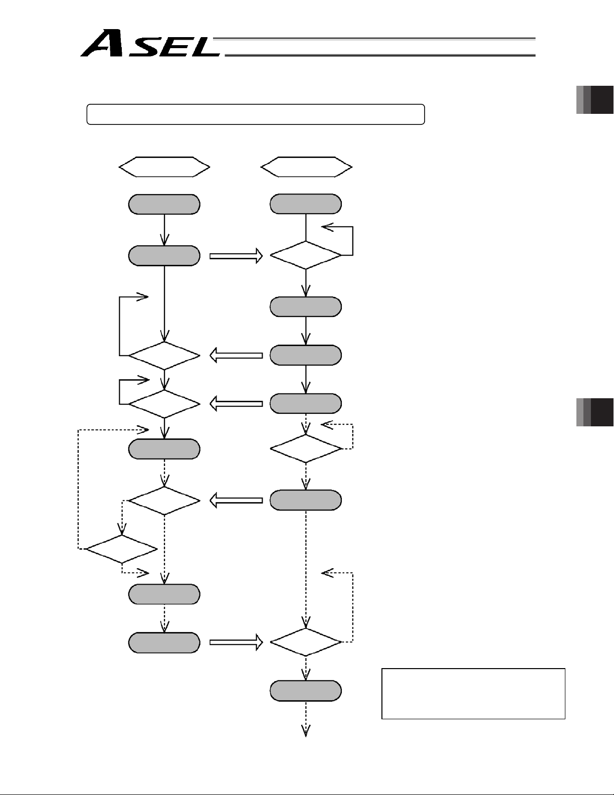
3.2 Starting via External Signal Selection
Part 1 Installation
Select a desired program number externally and then input a start signal.
(1) Flow chart
Controller
Power ON
Ready output
READY signal ON
External device
Power ON
READY signal
confirmed?
N
Y
Various I/O
processing
Program number
N
Program number
confirmed?
input
Program number
specification
Y
External start input
N
Start signal
confirmed?
Start signal ON
Y
Program run
N
Emergency-stop
signal confirmed?
Emergency-stop
input
Emergency-stop
switch ON?
Y
Emergency-stop
signal ON
N
Y
N
Controller
error?
Y
Part 1 Installation
When the READY signal (Output
port No. 301) turns ON, the RDY
lamp (green) on the controller front
panel will illuminate.
Input a desired program number as
a BCD code from the external
device (Input port Nos. 16 through
22).
Input a start signal (input port No. 0)
from the external device.
Chapter 4 Operation
If the optional panel unit is
connected, the CODE display area
indicates the program number of
each program that has been
started.
If an emergency-stop signal was
input from the external device or a
controller error occurred, the
controller will turn off the servo
power. (The RDY lamp will turn
off.)
Servo OFF
ALARM signal ON
Alarm output
ALARM signal
confirmed?
Y
ALARM
processing
N
Note) The assignments of dedicated
input/output port functions (such
as RDY output start signal)
reflect the factory settings.
57
Page 80

[2] Timing chart
[1] Program start
Part 1 Installation
Ready output
Program number
input
External start
input
Part 1 Installation
[2] Auto program start
* Set input function specification value 5 (auto-start program start signal) for input port No. *.
Ready output
Auto-start program
start signal input
Auto program
start
[3] Soft reset signal
* Set input function specification value 3 (soft reset signal) for input port No. *.
Ready output
Soft reset signal
input
Program starting
[4] Servo ON signal
* Set input function specification value 4 (servo ON signal) for input port No. *.
Ready output
Servo ON signal
input
Servo ON
Chapter 4 Operationg
Program 1
Program 2
T1: Duration after the ready output turns ON until
input of external start signal is permitted
T1 = 10 msec min.
T2: Duration after the program number is input
until input of external start signal is permitted
T2 = 50 msec min.
T3: Input duration of external start signal
T3 = 100 msec min.
T1: Time after the ready output turns ON until the
auto-start program start signal can be input to
input port No. *
T1 = 10 msec min.
* Auto program start:
Set “0” in other parameter No. 7, “Auto program
start setting.”
T1: T1: Time after the ready output turns ON until
input function specification value 3 (soft reset
signal) can be input to input port No. *
T1 = 10 msec min.
T2: T2: Time until the soft reset signal becomes
effective
T2 = 1 sec min.
T3: Time after the soft reset signal is cancelled
until the ready signal is output
T1: Time after the ready output turns ON until input
function specification value 4 (servo ON signal)
can be input to input port No. *
T1 = 10 msec min.
T2: Interval after the servo is turned OFF until it is
turned ON again
T2 = 1.5 sec min.
Warning : Turning the servo ON near the mechanical end may disturb the magnetic pole phase detection,
and may cause the magnetic pole unconfirmed error or the magnetic pole detection error.
Put the slider or rod away from the mechanical end when turning the servo ON.
[5] When the recovery type after emergency stop or enable operation is set to “Operation continued”
* Set other parameter No. 10 to “2,” and set input function specification value 7 (operation-pause reset signal) for input port
No. *. Set input function specification value 17 (drive-source cutoff reset input signal) for other input port No. *.
Program starting
Emergency stop
Drive-source
cutoff reset
Pause reset
T1: Time after the emergency stop input is reset until
the drive-source cutoff reset signal can be input.
T1 = 2 sec min.
T2: Time during which the drive-source cutoff reset
signal is input
T1 = 10 msec min.
T3: Time during which the pause reset signal is input
T1 = 10 msec min.
58
Page 81

Part 1 Installation
4. Drive-Source Recovery Request and Operation-Pause Reset Request
(1) Drive-source recovery request
[1] Case where a drive-source request is required
A drive-source recovery request is required in the following case:
x Specify a desired input port for receiving the drive-source cutoff reset input signal (dedicated
function).
Occurrence of a drive-source cutoff factor o Recovery after the cutoff factor is removed.
[2] How to request a drive-source recovery
A drive-source recovery request can be issued using one of the following methods:
x Set the input function specification value “17” in the I/O parameter corresponding to the desired
input port number (Nos. 30 through 45, 251 through 258). (Refer to “I/O Function Lists” and
“I/O Parameters.”)
Input the ON edge to the input port of the specified number.
x Select [Drive-Source Recovery Request (P
screen.
x Select Ctl (controller operation) and RPwr (drive-source recovery request) on the mode
selection screen of the teaching pendant.
(2) Operation-pause reset request
[1] Cases where an operation-pause reset request is required
An operation-pause reset request is required in any of the following cases:
x An emergency stop was actuated during automatic operation when other parameter No. 10
was set to “2” (Emergency-stop recovery type = Continued operation) (only during automatic
operation) o Recovery (reset of operation pause) after the emergency stop is reset.
x The automatic operation was stopped using the deadman switch or enable switch when other
parameter No. 11 was set to “2” (Deadman/enable switch recovery type = Continued
operation) (only during automatic operation) o Recovery (reset of operation pause) after the
stop is reset.
x Specify a desired input port for receiving the operation-pause input signal (dedicated function).
Set the input function specification value “8” in the I/O parameter corresponding to the desired
input port number (Nos. 30 through 45, 251 through 258). (Refer to “I/O Function Lists” and
“I/O Parameters.”)
OFF level signal input is received by the import port of the specified number during auto
operation (operations pause) o Recovery after detection of ON signal level by the input port
(operation pause is reset).
)] from the [Controller (C)] menu on the PC software
Part 1 Installation
Chapter 4 Operation
[2] How to request an operation-pause reset
An operation-pause reset request can be issued using one of the following methods:
x Specify a desired input port for receiving the operation-pause input signal (dedicated function).
Set the input function specification value “7” in the I/O parameter corresponding to the desired
input port number (Nos. 30 through 45, 251 through 258). (Refer to “I/O Function Lists” and
“I/O Parameters.”)
Input the ON edge to the input port of the specified number.
x Select [Operation-Pause Reset Request (L
screen.
x Select Ctl (controller operation) and RAct (operation-pause reset request) on the mode
selection screen of the teaching pendant.
* If the case in [1] of (1) and any of the cases in [1] of (2) are present at the same time, a drive-source
recovery request must be issued first, followed by an operation-pause reset request.
)] from the [Controller (C)] menu on the PC software
59
Page 82

5. Controller Data Structure
The controller data consists of parameters as well as position data and application programs used to
implement SEL language.
Part 1 Installation
Part 1 Installation
ASEL Controller Data Structure
Main
SEL language
The user must create position data and application programs. The parameters are predefined, but their
settings can be changed in accordance with the user’s system.
Refer to Appendix, “List of Parameters,” for details on the parameters.
Chapter 4 Operationg
Parameters
Position
data
Application
programs
60
Page 83

5.1 How to Save Data
Part 1 Installation
The flow to save data in the ASEL controller is illustrated below.
When data is transferred from the PC software or teaching pendant to the controller, the data is only
written to the main CPU memory as shown in the diagram below and will be erased once the controller is
powered down or reset.
For important data, always write to the flash memory so that they will not be lost.
5.1.1 Factory Settings: When the System-Memory Backup Battery is Not Used
Other parameter No. 20 = 0 (System-memory backup battery not installed)
Data edited on the PC
or teaching pendant
Transfer
PC
software,
TP
Transfer
Data will be retained while the power
is on and cleared upon reset
Main CPU memory
Programs
Parameters (other than
encorder parameters)
Symbols
Positions
Encoder parameters
Write to flash memory
Transfer upon reset
Transfer
Data will be retained even after
the power is turned off
Main CPU flash memory
Slave card memory
Part 1 Installation
Chapter 4 Operation
Transfer upon reset
SEL global data (flags,
variables, strings)
Error lists
Since the programs, parameters and symbols are read from the flash memory at restart, the data in the
temporary memory will remain the same as the original data before edit unless the edited data are written
to the flash memory.
The controller always operates in accordance with the data in the main CPU memory (excluding the
parameters).
Note: SEL global data cannot be retained if the backup battery is not installed.
SEL global data will be cleared once the control power is turned off or a software reset is
executed.
The error list will be cleared once the control power is turned off.
61
Page 84

5.1.2 When the System-Memory Backup Battery (Optional) is Used
Change the setting of other parameter No. 20 to 2 (System-memory backup battery installed).
Part 1 Installation
Data edited on the PC
or teaching pendant
Part 1 Installation
PC
software,
TP
Transfer
Transfer
Data will be retained while the power
is on and cleared upon reset
Main CPU memory
Programs
Parameters (other than
encorder parameters)
Symbols
Encoder parameters
Transfer
Write to flash memory
Transfer upon reset
Transfer
Transfer upon reset
Data will be retained even after
the power is turned off
Main CPU flash memory
Slave card memory
Battery backup memory
Positions
Since the programs, parameters and symbols are read from the flash memory at restart, the data in the
Chapter 4 Operationg
temporary memory will remain the same as the original data before edit unless the edited data are written
to the flash memory.
The controller always operates in accordance with the data in the main CPU memory (excluding the
parameters).
SEL global data (flags,
variables, strings)
Error lists
62
Page 85

5.2 Points to Note
Part 1 Installation
Point to note when transferring data and writing to the flash memory
Never turn off the main power while data is being transferred or written to the flash
memory. The data will be lost and the controller operation may be disabled.
Point to note when saving parameters to a file
The encoder parameters are stored in the EEPROM of the actuator’s encoder itself (unlike other
parameters, they are not stored in the EEPROM of the controller). The encoder parameters will be
read from the encoder’s EEPROM to the controller when the power is turned on or upon software
reset.
Therefore, if the parameters are saved to a file after turning on the controller (or restarting it via a
software reset) without an actuator (encoder) connected, the encoder parameters saved to the file
will become invalid.
Point to note when transferring a parameter file to the controller
When a parameter file is transferred to the controller, the encoder parameters will be transferred to
the EEPROM of the encoder (excluding manufacturing/function information).
Therefore, if the parameter file transferred to the controller has been read from a controller that was
started without an actuator connected, invalid encoder parameters will be written to the encoder’s
EEPROM (provided that an actuator is connected to the controller to which the file was transferred).
Part 1 Installation
When saving the parameters to a file, do so with an actuator connected to the controller.
Chapter 4 Operation
63
Page 86

Part 1 Installation
Chapter 5 Maintenance
x Routine maintenance and inspection are necessary so that the system will operate properly at all
times. Be sure to turn off the power before performing maintenance or inspection.
x The standard inspection interval is six months to one year. If the environment warrants, however, the
interval should be shortened.
1. Inspection points
Part 1 Installation
x Check to see if the supply voltage to the controller is inside the specified range.
x Inspect the ventilation holes in the controller and remove dirt, dust and other foreign attachments, if
x Inspect the controller cables (controller o actuator) and check for any loose screws or cable
x Check the controller mounting screws, etc., for looseness.
x Inspect each cable (axis link cable, general-purpose I/O cable, system I/O cable, power cable) for
2. Spare consumable parts
Without spare parts, a failed controller cannot be repaired even when the problem is identified quickly.
We recommend that you keep the following consumable parts as spares:
Consumable parts
x Cables
x System-memory backup battery (optional): AB-5 by IAI -- Must be replaced after approx. 5 years*
x Absolute-data backup battery (optional): AB-5 by IAI -- Must be replaced after approx. 2 years*
(Absolute specification)
When the battery voltage drops, an applicable error code will be displayed on the panel window.
any.
disconnection.
loose connection, disconnection, play, etc.
*: The actual replacement timing will vary depending on the use condition. For details, refer to “
Battery Backup Function” in Appendix.
Chapter 5 Maintenanceg
64
Error Codes Indicating Low Battery Voltage
System-memory backup battery A01 or A02
Absolute-data backup battery A23
Page 87

Part 1 Installation
3. Replacement Procedure for System-Memory Backup Battery (Optional)
Backing up the system memory
If the optional system-memory backup battery is installed in the ASEL controller and “Other parameter
No. 20: Backup battery installation function type” is set to “2” (Installed), the following SRAM data will
be retained even after the power is turned off:
x Position data
x SEL global data (flags, integer/real variables, string variables)
x Error list
Always follow the procedure below when replacing the system-memory backup battery:
Note: If the system-memory backup battery is disconnected while other parameter No. 20, “Backup
battery installation function type” is still set to “2” (Installed), the data stored in the SRAM will
be lost.
So that the position data can be restored after an accidental loss from the SRAM, save the
position data to a file using the PC software before disconnecting the battery.
For the method to save the position data to a file, refer to 6, “Position Data Edit Window” in
the X-SEL PC Software Operation Manual.
(1) Turn on the controller power.
(2) Record (write down) the current setting of “Other parameter No. 20, Backup-battery installation
function type.” (This will be used when reverting the parameter to its original setting following the
replacement of system-memory backup battery.)
Part 1 Installation
(3) If the PC software is installed in your PC, save the position data to a file using the PC software.
The data will be used as a backup in case the SRAM data saved to the flash ROM fails.
(4) Change “Other parameter No. 20, Backup-battery installation function type” to “1” and transfer
the setting to the controller, and then perform a flash ROM write. (The point data will be saved to
the flash ROM.)
* Confirm that the flash ROM writing process has completed.
(5) Perform a software reset to restart the controller. (The SEL global data and error lists will be
saved to the special area in the flash ROM.)
(6) When the controller has been restarted, turn off the power.
* Be sure to keep the power on from the start of controller restart until the RDY LED lamp on teh controller
illuminates.
(7) Replace the system-memory backup battery. SRAM data will be lost if steps (1) through (6) are
not performed properly.
Chapter 5 Maintenance
65
Page 88

Battery Replacement Procedure
Part 1 Installation
Part 1 Installation
[1] Remove the battery connector and pull out the
battery.
[2] Insert a new battery into the holder and plug in the
battery connector. The connector hook should face
the right side.
(8) When the replacement of system-memory backup battery is complete, confirm that the battery is
installed securely and then turn on the controller power.
(9) Revert “Other parameter No. 20, Backup-battery installation function type” to the value recorded in
step (2), transfer the setting to the controller, and then perform a flash ROM write.
* Confirm that the flash ROM writing process has completed.
(10) Perform a software reset (restart the controller).
(Note) Commencing the operation without first executing a software reset or reconnecting the
Chapter 5 Maintenanceg
(11) When the controller has been restarted, confirm that the SRAM data have been restored.
power may generate the following errors:
Error No. C70: ABS coordinate non-confirmation error
Error No. C6F: Home-return incomplete error
66
Page 89

Part 1 Installation
4. Replacement Procedure for Absolute-Data Backup Battery (Optional)
The replacement procedure is different depending on which error is present (No. A23, 914, CA2), or if
no error is present at all, when the battery is replaced.
x If no error is present, perform steps (1) to (4).
x If an absolute-data backup battery voltage-low warning (Error No. A23) has been issued, perform
steps (1) to (11).
x If an absolute-data backup battery voltage error (Error No. 914 or CA2) has been issued, perform
steps (1) to (4) and then perform the procedure explained in Chapter 4-2 of Part 1 “How to Perform
Absolute Reset.”
Note: Among the steps explained below, complete (2) to (4) within 15 minutes.
(1) Turn off the controller power. (Turn off both the control power and drive power.)
(2) Remove the battery connector and pull out
the battery.
Part 1 Installation
(3) Insert a new battery into the holder and plug
in the battery connector. The connector
hook should face the right side.
Chapter 5 Maintenance
67
Page 90

(4) Turn on the controller power.
(5) Start the PC software on a PC connected to the controller. From the C
A
(6) When the Warning dialog box appears, click OK.
Part 1 Installation
(7) The Absolute Reset dialog box appears.
Part 1 Installation
ontroller menu, select
bsolute Reset.
Warning
(8) Set the address number corresponding to
the axis whose battery has just been
replaced.
Note) Do not click Encoder Rotation Data
Reset 1.
(11) In the PC software window, click the C
controller.
Chapter 5 Maintenanceg
(Note) If you continue to operate the controller without resetting the software or reconnecting the power, the
following errors may generate:
Error No. C70: ABS coordinate non-confirmation error
Error No. C6F: Home-return incomplete error
This completes the procedure to reset a battery voltage low alarm/error.
68
(9) Click Encoder Error Reset.
(10) Close the dialog box.
Absolute Reset
ontroller menu and then select Software Reset to restart the
Confirmation
Page 91

Part 2 Programs
Chapter 1 SEL Language Data
Part 2 Programs
1. Values and Symbols Used in SEL Language
1.1 List of Values and Symbols Used
The various functions required in a program are represented by values and symbols.
Function Global range Local range Remarks
Input port 000 ~ 299 (300)
Output port 300 ~ 599 (300)
Flag 600 ~ 899 (300) 900 ~ 999 (100)
Variable (integer)
Variable (real)
String 300 ~ 999 (700) 1 ~ 299 (299)
Tag number 1 ~ 256 (256)
Subroutine number 1 ~ 99 (99)
Zone number 1 ~ 4 (4)
Pallet number 1 ~ 10 (10)
Axis number 1 ~ 2 (2)
Axis pattern 0 ~ 11
Position number 1 ~ 1500 (1500)
Program number 1 ~ 64 (64)
Step number 1 ~ 2000 (2000)
Task level NORMAL/HIGH (2)
SIO channel number 0 (1)
Wait timer 1
1-shot pulse timer
Ladder timer Local flag (100)
Virtual input port (SEL
system o SEL user
program)
Virtual output port (SEL user
program o SEL system)
Number of symbol definitions 500
Number of times symbol can
be used in commands
200 ~ 299 (100)
1200 ~ 1299 (100)
300 ~ 399 (100)
1300 ~ 1399 (100)
7000 ~ 7299 (300)
7300 ~ 7599 (300)
2500 (including literals)
Used in common from any
program.
Referenced separately in
each program.
Cleared when the program
is started.
1 ~ 99 (99)
1001 ~ 1099 (99)
100 ~ 199 (100)
1100 ~ 1199 (100)
16 (Number of timers that
can be operated
simultaneously)
Varies depending on the
function.
Varies depending on the
function.
99 is used for IN, INB,
OUT, OUTB, etc.
199 is used for PPUT,
PGET, PARG, etc.
Varies depending on the
function.
Part 2 Programs Chapter 1 SEL Language Data
Caution
x Variables 99 and 199 are special variables this system uses in operations.
Avoid using these two variables for general purposes.
x The values in the table represent ranges that can be processed by
software. Items that require physical devices, such as I/O ports and
functions relating to axis number and SIO, will be determined by possible
combinations and models of commercial boards, etc., available for each
device application.
69
Page 92

z If the optional system-memory backup battery is installed, data of global variables and flags will be
retained even after the controller power is turned off.
(Other parameter No. 20 must be set to “2.” Refer to 5.1.2, “When the System Memory Backup Battery
is Used” in Chapter 5 of Part 1.)
z The variables and flags in the local range will be cleared when the program is started.
z Ranges of values that can be used in SEL language
Integers and real numbers can be used. However, pay due attention to the following limitations:
(1) Numeric data
The ASEL Controller can handle values of maximum eight digits including a sign and a decimal point.
Part 2 Programs
Integer: -9,999,999 to 99,999,999
Real number: Maximum eight digits including a sign and decimal point, regardless of the size of value
Example) 999999.9, 0.123456, -0.12345
If a floating point is used in operations, the number of valid digits will be limited to seven. Also note
that operations using a floating point are subject to error.
(2) Position data
The input range of position data consists of four integer digits and three decimal digits.
–9999.999 to 9999.999
(The maximum value varies depending on the actuator model.)
If position data are used in internal operations as numeric data (repeated multiplications and divisions),
the accuracy of the last digit may decrease.
Part 2 Programs
1.2 I/O Ports
Chapter 1 SEL Language Data
Consider the above limitations fully when using values. Particularly when the CPEQ command is used
in a comparison operation using real numbers, a match will rarely result. In this case, the CPLE or
CPGE command that looks at the magnitude relationship of two terms must be used.
(1) Input ports
Used as input ports for limit switches, sensor switches, etc.
Input number assignment
000 to 023 (standard)
(2) Output ports
Used as various output ports.
Output number assignment
300 to 307 (standard)
70
Page 93

1.3 Virtual I/O Ports
(1) Virtual input ports
Port No. Function
7000 Always OFF
7001 Always ON
7002 Voltage low warning for system-memory backup battery
7003 Abnormal voltage of system-memory backup battery
7004 (For future expansion = Use strictly prohibited)
7005 (For future expansion = Use strictly prohibited)
7006 Top-level system error = Message level error is present
7007 Top-level system error = Operation-cancellation level error is present
7008 Top-level system error = Cold-start level error is present
7009 (For future expansion = Use strictly prohibited)
7010 Drive-source cutoff factor is present (including when waiting for cutoff reset input)
7011
7012
7013
7014 (For future expansion = Use strictly prohibited)
7015 Voltage low warning for axis-1 absolute-data backup battery
7016
7017 Voltage low warning for axis-2 absolute-data backup battery
7018
7019 ~ 7026 (For future expansion = Use strictly prohibited)
7027 ~ 7040 (For future expansion = Use strictly prohibited)
7041 ~ 7070 (For future expansion = Use strictly prohibited)
7071 In AUTO mode
7072 During automatic operation
7073 ~ 7100 (For future expansion = Use strictly prohibited)
7101 Running program No. 01 (including during pause)
~ ~
7164 Running program No. 64 (including during pause)
7165 ~ 7299 (For future expansion = Use strictly prohibited)
Latch signal indicating that all-operation-cancellation factor is present (latch signal for
recognizing 1-shot cancellation factor; latch is cancelled by 7300-ON)
All-operation-pause factor is present (including when waiting for restart switch signal) (Valid
only during automatic operation recognition)
All-servo-axis-interlock factor is present (all-operation-pause factor + interlock input-port
factor)
Abnormal voltage of axis-1 absolute-data backup battery (latched until power-on reset or
software reset)
Abnormal voltage of axis-2 absolute-data backup battery (latched until power-on reset or
software reset)
Part 2 Programs
Part 2 Programs Chapter 1 SEL Language Data
71
Page 94

(2) Virtual output ports
Port No. Function
Latch cancellation output for a latch signal indicating that all-operation-cancellation factor
7300
is present (7011) (latch is cancelled only when operation-cancellation factor is no longer
present) (7300 will be turned OFF following an attempt to cancel latch.)
7301 ~ 7380 (For future expansion = Use strictly prohibited)
7381 ~ 7399 (For future expansion = Use strictly prohibited)
Part 2 Programs
Part 2 Programs
Chapter 1 SEL Language Data
7400 ~ 7599 (For future expansion = Use strictly prohibited)
72
Page 95
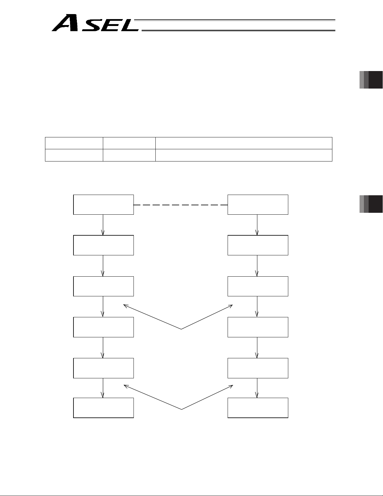
Part 2 Programs
1.4 Flags
Contrary to its common meaning, the term “flag” as used in programming means “memory.” Flags are
used to set or reset data. They correspond to “auxiliary relays” in a sequencer.
Flags are divided into global flags (Nos. 600 to 899) that can be used in all programs, and local flags (Nos.
900 to 999) that can be used only in each program.
Global flags will be retained (backed up by battery) even after the power is turned off.
Local flags will be cleared when the power is turned off.
Flag number 600 ~ 899 Can be used in all programs “Global flags”
Flag number 900 ~ 999 Used only in each program “Local flags”
Program 1 Program n
Part 2 Programs Chapter 1 SEL Language Data
BTON 600
Turn on flag 600
(Like this, global flags can be
used to exchange signals.)
WTON 600
Wait for flag 600 to turn ON
BTON 900 BTON 900
(Although the number is the
same, these are local flags and
can exist only in their
respective programs.)
73
Page 96

1.5 Variables
(1) Meaning of variable
“Variable” is a technical term used in software programming. Simply put, it means “a box in which a value
is put.” Variables can be used in many ways, such as putting in or taking out a value and performing
addition or subtraction.
Part 2 Programs
Part 2 Programs
A variable can be used in many ways, such as:
Putting in a value (1234),
Taking out a value (456), or
Command Operand 1 Operand 2
If this command is applied to variable box 1, which already contains 2, then 1 will be added to the current
Chapter 1 SEL Language Data
value and 3 will result.
Variable
box 1
ADD 1 1
Adding a value (+1).
1 is added.
74
Variable
box 1
2
(Already contains 2)
Page 97

(2) Types of variables
Variables are classified into two types, as follows:
[1] Integer variables
These variables cannot handle decimal places.
[Example] 1234
Integer variable box
Variable
box 1
Part 2 Programs
Part 2 Programs Chapter 1 SEL Language Data
1 2 3 4
Integer variable number
Integer variable number
200 ~ 299
1200 ~ 1299
1 ~ 99
1001 ~ 1099
Can be used in all programs “Global integer variables”
Used only in each program “Local integer variables”
Integer 99 is a special register this system uses in integer
Caution
operations. Any value in the range from –9,999,999 to
99,999,999 can be input in programs.
[2] Real variables
Actual values. These variables can handle decimal places.
[Example] 1234.567
(Decimal point)
Real variable box
Variable
box 1
1234.567
Real variable number
Real variable number
Caution
300 ~ 399
1300 ~ 1399
100 ~ 199
1100 ~ 1199
Can be used in all programs “Global real variables”
Used only in each program “Local real variables”
Real number 199 is a special register this system uses in realnumber operations. Any value in the range from –99,999.9 to
999,999.9 (eight digits including a sign) can be input in
programs.
75
Page 98

Part 2 Programs
[3] Variables with “*” (asterisk) (indirect specification)
An “*” (asterisk) is used to specify a variable.
In the following example, the content of variable box 1 will be put in variable box 2. If variable box 1
contains “1234,” then “1234” will be put in variable box 2.
Command Operand 1 Operand 2
LET 1 1234
1 2 3 4
Part 2 Programs
Chapter 1 SEL Language Data
Variable
box 1
1 2 3 4
Command Operand 1 Operand 2
LET 2 *1
Variable
box 2
1 2 3 4
Put in.
Variable
box 1
1 2 3 4
The above use of variables is called “indirect specification.”
An “*” is also used when indirectly specifying a symbol variable (refer to 1.8, “Symbols”).
Command Operand 1 Operand 2
LET ABC 1
LET BCD 2
ADD ABC *BCD
Put 1 in variable ABC.
Put 2 in variable BCD.
Add the content of variable BCD, or 2, to variable ABC.
(The content of variable ABC becomes 3.)
76
Page 99

Part 2 Programs
1.6 Tags
The term “tag” means “heading.”
Tags are used in the same way you attach labels to the pages in a book you want to reference frequently.
A tag is a destination specified in a jump command “GOTO.”
Tag
Part 2 Programs Chapter 1 SEL Language Data
Command Operand 1
TAG Tag number (Integer between 1 and 256)
They are used only in each program.
TAG 1
GOTO 1
77
Page 100

1.7 Subroutines
By taking out the parts of a program that are used repeatedly and registering them as “subroutines,” the
same processing can be performed with fewer steps. (A maximum of 15 nests are accommodated.)
They are used only in each program.
Command Operand 1
Subroutine execution command
Part 2 Programs
Command Operand 1
Subroutine start declaration
Command Operand 1
Subroutine end declaration
Part 2 Programs
EXSR Subroutine number (Integer between 1 and 99; variable is also supported)
BGSR Subroutine number (Integer between 1 and 99)
EDSR
Chapter 1 SEL Language Data
EXSR 1
Subroutines are called.
EXSR 1
EXSR 1
BGSR 1
Subroutines
EDSR
78
 Loading...