

Page 1

X-SEL Controlle
r
PX/QX Type
Operation ManualSeventh Edition
Tenth Edition
Page 2

Page 3

Please Read Before Use
Thank you for purchasing our product.
This Operation Manual explains the handling methods, structure and maintenance of this product, among
others, providing the information you need to know to use the product safely.
Before using the product, be sure to read this manual and fully understand the contents explained herein
to ensure safe use of the product.
The CD or DVD that comes with the product contains operation manuals for IAI products.
When using the product, refer to the necessary portions of the applicable operation manual by printing
them out or displaying them on a PC.
After reading the Operation Manual, keep it in a convenient place so that whoever is handling this product
can reference it quickly when ne
cessary.
• This Operation Manual is original.
• The product cannot be operated in any way unless expressly specified in this Operation Manual. IAI
shall assume no responsibility for the outcome of any operation not specified herein.
• Information contained in this Operation Manual is subject to change without notice for the purpose of
product improvement.
• If you have any question or comment regarding the content of this manual, please contact the IAI
sales office near you.
• Using or copying all or part of this Operation Manual without permission is prohibited.
• The company names, names of products and trademarks of each company shown in the sentences
are registered trademarks.
[Important]
Page 4

CAUTION
Operator Alarm on Low Battery Voltage
This controller is equipped with the following backup batteries for retention of data in the event of power
failure:
[1] System-memory backup battery
For retention of position data, global variables/flags, error list, strings, etc.
[2] Absolute encoder backup battery
For retention of encoder rotation data.
Since these batteries are not rechargeable, they will eventually be consumed. Unless the batteries are
replaced in a timely manner, the voltage will drop to a level where the data can no longer be retained. If a
power failure occurs in this condition, the data will be lost (The life of each battery varies depending on the
operating time).
turned on.
(Reference)
System-memory backup battery --- An alarm occurs when the voltage drops to approximately 2.6 V.
Absolute-encoder backup battery --- An alarm occurs when the voltage drops to approximately 3.2 V.
Once the data is lost, the controller will not operate normally the next time the power is
Data backup becomes impossible at a battery voltage of
approximately 2.3 V (rated voltage: 3.0 V).
Data backup becomes impossible at a battery voltage of
approximately 2.7 V (rated voltage: 3.6 V).
To prevent this problem, the controller can output a low battery voltage alarm from its I/O port.
Output port No. 313 is assigned as an alarm output for low system-memory backup battery voltage.
Output port No. 314 is assigned as an alarm output for low absolute-encoder backup battery voltage.
It is recommended that this function be utilized to prevent unnecessary problems resulting rom low battery
voltage (consumption of battery life).
The person in charge of system design should utilize this function to provide a method for issuing an
operator alarm using an output signal from an I/O port, while the person in charge of electrical design
should provide a circuit implementation that has the same effect.
Refer to the applicable section in the operating manual for the batter replacement.
It is recommended that you always backup the latest data to a PC in case of voltage drop in teh systemmemory backup battery or unexpected controller failure.
Compatible Teaching Pendant/PC Software
QX controllers only support the following teaching pendant/PC software:
Teaching pendant: IA-T-XA (ANSI type)
PC software: IA-101-XA-MW (with category 4 cable)
Page 5

CAUTION
Notes on Supply of Brake Power (+24 V)
Besides connecting the brake power cable from the SCARA robot, the brake power must also be supplied
to the controller.
Follow the illustration below to supply the brake power (+24 V) also to the controller.
200 to 230 VAC
power supply
Auxiliary power
circuit
Top: 0 V
Bottom: 24 V
Example of X-SEL-PX
controller (4-axis SCARA
robot of 250 to 600 mm in
arm length, without
expansion I/Os)
Brake power
+24-V power
supply
Power-supply capacity
45 W: Arm length 500 to 800
23 W: Arm length 250 to 350
14 W: Arm length 120 to 150
SCARA robot
(Note) When the arm length is
120 to 180, the brake
power need not be
supplied to the robot.
Page 6

CAUTION
Drive-source Cutoff Relay Error (Detection of Fused Relay: E6D)
Because of their circuit configuration, XSEL-PX controllers of single-phase, standard specification are the
only class of controllers that may generate a “drive-source cutoff relay error (E6D),” notifying fusion of an
internal relay, when the time after the power is turned off until it is turned back on (= until the power is
reconnected) is too short.
Although the specific time varies depending on the input voltage and number of external regenerative
resistance boxes being connected, as a guide wait for at least 40 seconds before reconnecting the power.
Page 7

CAUTION
Note on Controllers with Increased CPU Unit Memory Size
* Controllers with gateway function come with an increased memory size in their CPU unit.
If you are using a controller with increased CPU unit memory size, use PC software and teaching
pendants of the versions specified below.
Teaching tool Version
X-SEL PC software V7.2.0.0 or later
Teaching pendant SEL-T/TD V1.01 or later
[How to Check if Controller Has Increased Memory Size]
Check the ROM version information in the PC software (Version 6.0.0.0 or later) (by selecting
Controller (C)
teaching pendant (IA-T-X, IA-T-XD: Version 1.121 or later / SEL-T, SEL-TD: Version 1.00 or later) (by
selecting Moni
If the memory size has been increased: On the PC software screen, you will see “Main
About ROM (V)), or check the main CPU firmware version information on the
Ver Main).
(FROM32M),” as shown below. On the teaching pendant
screen, you will see “Main (FROM32M),” as shown below.
Checking in PC Software
Checking on Teaching Pendant
Page 8

Page 9

Table of Contents
Table of Contents
Safety Guide.................................................................................................................................. 1
Introduction.................................................................................................................................... 1
Part 1 Installation ....................................................................................................................... 4
Chapter 1 Safety Precautions............................................................................................................... 4
Chapter 2 Warranty Period and Scope of Warranty ............................................................................. 5
1. Warranty Period........................................................................................................................... 5
2. Scope of Warranty....................................................................................................................... 5
3. Scope of Service ......................................................................................................................... 5
Chapter 3 Installation Environment and Selection of Auxiliary Power Devices.................................... 6
1. Installation Environment .............................................................................................................. 6
2. Heat Radiation and Installation.................................................................................................... 7
3. Selection of Auxiliary Power Devices .......................................................................................... 8
4. Noise Control Measures and Grounding................................................................................... 13
Chapter 4 Name and Function of Each Part....................................................................................... 16
1. Front View of Controller............................................................................................................. 16
2. Explanation of Codes Displayed on the Panel Window ............................................................ 30
2.1 Application....................................................................................................................... 30
2.2 Core................................................................................................................................. 31
2.3 Current Monitor and Variable Monitor ............................................................................. 32
Chapter 5 Specifications ..................................................................................................................... 34
1. Controller Specifications............................................................................................................ 34
2. External I/O Specifications......................................................................................................... 38
2.1. NPN Specification............................................................................................................ 38
2.2. PNP Specification............................................................................................................ 40
3. Power Source Capacity and Heat Output ................................................................................. 42
4. External Dimensions.................................................................................................................. 48
Chapter 6 Safety Circuit...................................................................................................................... 57
1. Items to Notes ........................................................................................................................... 57
2. Safety Circuit for PX Type (Standard Specification) Controller ................................................. 58
3. Safety Circuit for QX Type (Global Specification) Controller ..................................................... 60
4. Timing Chart of Safety Circuit for QX-type SEL Controller........................................................ 65
Chapter 7 System Setup..................................................................................................................... 74
1. Connection Method of Controller and Actuator ......................................................................... 74
2. I/O Connection Diagram............................................................................................................ 78
3. Multipoint DIO Board ................................................................................................................. 81
3.1 Overview ......................................................................................................................... 81
3.2 Specifications .................................................................................................................. 81
3.3 External Interface Specifications..................................................................................... 82
Multipoint I/O Board Connection Cables......................................................................... 83
3.4
3.5 Multipoint I/O Board Connection Cables......................................................................... 84
3.6 I/O Circuits....................................................................................................................... 85
Page 10

Table of Contents
Chapter 8 How to Perform An Absolute Encoder Reset of A Direct Movement Axis (Absolute
Specification)...................................................................................................................... 87
1. Preparation ................................................................................................................................ 87
2. Procedure .................................................................................................................................. 87
Chapter 9 Maintenance ...................................................................................................................... 93
1. Inspection Points ....................................................................................................................... 93
2. Spare Consumable Parts........................................................................................................... 94
3. Replacement Procedure for System Memory Backup Battery.................................................. 95
4. Replacement Procedure for Absolute-Encoder Backup Battery for Linear Movement Axis ..... 98
Part 2 Operation..................................................................................................................... 101
Chapter 1 Operation ......................................................................................................................... 101
1. Starting a Program by Auto Start via Parameter Setting ......................................................... 102
2. Starting via External Signal Selection...................................................................................... 103
3. Drive Source Recovery Request and Operation Pause Reset Request................................. 105
Chapter 2 Specoal Function..............................................................................................................106
1. Driver Overload Warning Function................................................................................................ 106
Part 3 Controller Data Structure............................................................................................. 109
Chapter 1 How to Save Data............................................................................................................ 110
1. Factory Settings: When the System Memory Backup Battery is Used ................................... 110
1.1 Controller without Increased Memory Size ................................................................... 110
1.2 Controller with Increased Memory Size (with Gateway Function) ................................ 111
2. When the System Memory Backup Battery is Not Used......................................................... 112
2.1 Controller without Increased Memory Size ................................................................... 112
2.2 Controller with Increased Memory Size (with Gateway Function) .................................113
3. Points to Note ...........................................................................................................................114
Chapter 2 X-SEL Language Data......................................................................................................116
1. Values and Symbols Used in SEL Language...........................................................................116
1.1 List of Values and Symbols Used...................................................................................116
1.2 I/O Ports .........................................................................................................................117
1.3 Virtual I/O Ports ..............................................................................................................118
1.4 Flags...............................................................................................................................120
1.5 Variables.........................................................................................................................121
1.6 Tags ............................................................................................................................... 124
1.7 Subroutines ................................................................................................................... 125
1.8 Symbols......................................................................................................................... 126
1.9 Character String Literals................................................................................................ 126
1.10 Axis Specification .......................................................................................................... 127
2. Position Part ............................................................................................................................ 129
3. Command Part ........................................................................................................................ 130
3.1 SEL language Structure ................................................................................................ 130
3.2 Extension Condition ...................................................................................................... 131
Page 11

Table of Contents
Part 4 Commands .................................................................................................................. 132
Chapter 1 List of SEL Language Command Codes ......................................................................... 132
Chapter 2 Explanation of Commands............................................................................................... 144
1. Commands .............................................................................................................................. 144
1.1 Variable Assignment...................................................................................................... 144
1.2 Arithmetic Operation...................................................................................................... 147
1.3 Function Operation........................................................................................................ 149
1.4 Logical Operation .......................................................................................................... 154
1.5 Comparison Operation .................................................................................................. 157
1.6 Timer ............................................................................................................................. 158
1.7 I/O, Flag Operation........................................................................................................ 161
1.8 Program Control ............................................................................................................ 172
1.9 Task Management ......................................................................................................... 175
1.10 Position Operation......................................................................................................... 180
1.11 Actuator Control Declaration ......................................................................................... 195
1.12 Actuator Control Command........................................................................................... 232
1.13 Structural IF ................................................................................................................... 264
1.14 Structural DO................................................................................................................. 267
1.15 Multi-Branching ............................................................................................................. 269
1.16 System Information Acquisition ..................................................................................... 273
1.17 Zone .............................................................................................................................. 277
1.18 Communication ............................................................................................................. 281
1.19 String Operation ............................................................................................................ 287
1.20 Palletizing-Related ........................................................................................................296
1.21 Palletizing Calculation Command ................................................................................. 311
1.22 Palletizing Movement Command ...................................................................................314
1.23 Building of Pseudo-Ladder Task ................................................................................... 320
1.24 Extended Commands .................................................................................................... 322
Chapter 3 Key Characteristics of Horizontal Articulated Robot (SCARA) Operation ....................... 327
1. CP Operation and PTP Operation ........................................................................................... 327
2. Arm System ............................................................................................................................. 330
3. SCARA Coordinate System..................................................................................................... 338
4. Simple Interference Check Zone (Dedicated SCARA Function) ............................................. 348
5. Soft Limits of SCARA Axes ...................................................................................................... 351
6. PTP Optimal Acceleration/Deceleration Function for SCARA Robot ...................................... 355
7. Horizontal move optimization function based on Z position for SCARA Robot....................... 357
Chapter 4 Key Characteristics of Actuator Control Commands and Points to Note......................... 359
1. Continuous Movement Commands [PATH, PSPL, CIR2, ARC2, CIRS, ARCS, ARCD, ARCC,
CIR, ARC]................................................................................................................................ 359
2. PATH/PSPL Commands .......................................................................................................... 361
3. CIR/ARC Commands .............................................................................................................. 361
4. CIR2/ARC2/ARCD/ARCC Commands.................................................................................... 361
Chapter 5 Palletizing Function.......................................................................................................... 362
Page 12

Table of Contents
1. How to Use .............................................................................................................................. 362
2. Palletizing Setting.................................................................................................................... 362
3. Palletizing Calculation ............................................................................................................. 368
4. Palletizing Movement .............................................................................................................. 369
5. Program Examples.................................................................................................................. 371
Chapter 6 Pseudo-Ladder Task ........................................................................................................ 375
1. Basic Frame............................................................................................................................. 375
2. Ladder Statement Field ........................................................................................................... 376
3. Points to Note .......................................................................................................................... 376
4. Program Example.................................................................................................................... 377
Chapter 7 Multi-Tasking .................................................................................................................... 378
1. Difference from a Sequencer................................................................................................... 378
2. Release of Emergency Stop.................................................................................................... 379
3. Program Switching .................................................................................................................. 380
Appendix ................................................................................................................................... 381
List of Additional Linear Movement Axis Specifications........................................................... 381
How to Write Programs ........................................................................................................... 387
1. Position Table.............................................................................................................. 387
2. Program Format.......................................................................................................... 388
3. Positioning to 5 Positions (for Linear Axes) ................................................................ 389
4. How to Use TAG and GOTO....................................................................................... 390
5. Back-and-Forth Operation between 2 Points (for Linear Axes).................................. 391
6. Path Operation............................................................................................................ 392
7. Output Control during Path Movement....................................................................... 393
8. Circular, Arc Operation................................................................................................ 394
9. Output of Home Return Complete Signal (for Linear Axes) ....................................... 395
10. Axis Movement by Input Waiting and Output of Complete Signal.............................. 396
11. Change of Moving Speed (for Linear Axes)................................................................ 397
12. Speed Change during Operation ................................................................................ 398
13. Local/Global Variables and Flags ............................................................................... 399
14. How to Use Subroutines ............................................................................................. 400
15. Pausing of Operation .................................................................................................. 401
16. Aborting of Operation 1 (CANC) ................................................................................. 402
17. Aborting of Operation 2 (STOP) ................................................................................. 403
18. Movement by Position Number Specification ............................................................. 404
19. Movement by External Position Data Input (for Linear Axes)..................................... 405
20. Output of Coordinate Values....................................................................................... 406
21. Conditional Jump ........................................................................................................ 407
22. Waiting for Multiple Inputs........................................................................................... 408
23. How to Use Offsets (for Linear Axes) ......................................................................... 409
24. Execution of Operation n Times ................................................................................. 410
25. Constant Pitch Feed Operation (for Linear Axes)....................................................... 411
26. Jogging (for Linear Axes)............................................................................................ 412
27. Program Switching...................................................................................................... 413
28. Aborting of Program.....................................................................................................414
General-purpose RS232 (2-channel RS232 Unit)................................................................... 415
Page 13

Table of Contents
Battery Backup Function ......................................................................................................... 422
1. System-Memory Backup Battery................................................................................ 422
2. Absolute-Encoder Backup Battery.............................................................................. 424
Expansion I/O Board (Optional)............................................................................................... 427
Number of Regenerative Units to be Connected..................................................................... 427
List of Parameters ................................................................................................................... 429
1. I/O Parameters ........................................................................................................... 430
2. Parameters Common to All Axes................................................................................ 447
3. Axis-Specific Parameters............................................................................................ 451
4. Driver Card Parameters.............................................................................................. 462
5. Encoder Parameters................................................................................................... 465
6. I/O Device Parameters ............................................................................................... 466
7. Other Parameters ....................................................................................................... 467
8. Manual Operation Types............................................................................................. 473
9. Use Examples of Key Parameters.............................................................................. 474
Combination Table of X-SEL PX/QX Axis 5/6 Linear/Rotary Control Parameter (Other than
SCARA
Axes).................................................................................................................................480
Error Level Control .......................................................................................................................... 481
Error List ......................................................................................................................................... 524
Troubleshooting of X-SEL Controller............................................................................................... 528
Servo Gain Adjustment for Linear Movement Axis.......................................................................... 531
Trouble Report Sheet...................................................................................................................... 533
Change History.......................................................................................................................... 534
Page 14

Page 15

Safety Guide
This “Safety Guide” is intended to ensure the correct use of this product and prevent dangers and property
damage. Be sure to read this section before using your product.
Regulations and Standards Governing Industrial Robots
Safety measures on mechanical devices are generally classified into four categories under the
International Industrial Standard ISO/DIS 12100, “Safety of machinery,” as follows:
Safety measures Inherent safety design
Protective guards --- Safety fence, etc.
Additional safety measures --- Emergency stop device, etc.
Information on use --- Danger sign, warnings, operation manual
Based on this classification, various standards are established in a hierarchical manner under the
International Standards ISO/IEC. The safety standards that apply to industrial robots are as follows:
Type C standards (individual safety standards) ISO10218 (Manipulating industrial robots – Safety)
JIS B 8433
(Manipulating industrial robots – Safety)
Also, Japanese laws regulate the safety of industrial robots, as follows:
Industrial Safety and Health Law Article 59
Workers engaged in dangerous or harmful operations must receive special education.
Ordinance on Industrial Safety and Health
Article 36 --- Operations requiring special education
No. 31 (Teaching, etc.) --- Teaching and other similar work involving industrial robots
(exceptions apply)
No. 32 (Inspection, etc.) --- Inspection, repair, adjustment and similar work involving industrial
robots (exceptions apply)
Article 150 --- Measures to be taken by the user of an industrial robot
Pre-1
Page 16

Requirements for Industrial Robots under Ordinance on Industrial Safety
and Health
Work area
movement
range
Inside
movement
range
Work
condition
During
automatic
operation
During
teaching, etc.
During
inspection,
etc.
Cutoff of drive source Measure Article
Signs for starting operation Article 104 Outside
Not cut off
Cut off (including
stopping of operation)
Not cut off
Cut off
Not cut off (when
inspection, etc., must
be performed during
operation)
Installation of railings, enclosures,
etc.
Sign, etc., indicating that work is in
progress
Preparation of work rules Article 150-3
Measures to enable immediate
stopping of operation
Sign, etc., indicating that work is in
progress
Provision of special education Article 36-31
Checkup, etc., before
commencement of work
To be performed after stopping the
operation
Sign, etc., indicating that work is in
progress
Preparation of work rules Article 150-5
Measures to enable immediate
stopping of operation
Sign, etc., indicating that work is in
progress
Provision of special education
(excluding cleaning and lubrication)
Article 150-4
Article 150-3
Article 150-3
Article 150-3
Article 151
Article 150-5
Article 150-5
Article 150-5
Article 150-5
Article 36-32
Pre-2
Page 17

Applicable Modes of IAI’s Industrial Robot
Machines meeting the following conditions are not classified as industrial robots according to Notice of
Ministry of Labor No. 51 and Notice of Ministry of Labor/Labor Standards Office Director (Ki-Hatsu No.
340):
(1) Single-axis robo with a motor wattage of 80 W or less
(2) Combined multi-axis robot whose X, Y and Z-axes are 300 mm or shorter and whose rotating
part, if any, has the maximum movement range of within 300 mm
part
(3) Multi-joint robot whose movable radius and Z-axis are within 300 mm
Among the products featured in our catalogs, the following models are classified as industrial robots:
1. Single-axis ROBO Cylinders
RCS2/RCS2CR-SS8 whose stroke exceeds 300 mm
2. Single-axis robots
The following models whose stroke exceeds 300 mm and whose motor capacity also exceeds 80 W:
ISA/ISPA, ISDA/ISPDA, ISWA/ISPWA, IF, FS, NS
3. Linear servo actuators
All models whose stroke exceeds 300 mm
4. Cartesian robos
Any robot that uses at least one axis corresponding to one of the models specified in 1 to 3
5. IX SCARA robots
All models whose arm length exceeds 300 mm
(All models excluding IX-NNN1205/1505/1805/2515, NNW2515 and NNC1205/1505/1805/2515)
3
including the tip of the rotating
Pre-3
Page 18

Notes on Safety of Our Products
Common items you should note when performing each task on any IAI robot are explained below.
No. Task Note
1 Model
selection
2 Transportation
3 Storage/
preservation
4 Installation/
startup
This product is not planned or designed for uses requiring high degrees of safety.
Accordingly, it cannot be used to sustain or support life and must not be used in
the following applications:
[1]Medical devices relating to maintenance, management, etc., of life or health
[2]Mechanisms or mechanical devices (vehicles, railway facilities, aircraft facilities,
etc.) intended to move or transport people
[3]Important safety parts in mechanical devices (safety devices, etc.)
Do not use this product in the following environments:
[1]Place subject to flammable gases, ignitable objects, flammables, explosives, etc.
[2]Place that may be exposed to radiation
[3]Place where the surrounding air temperature or relative humidity exceeds the
specified range
[4]Place subject to direct sunlight or radiated heat from large heat sources
[5]Place subject to sudden temperature shift and condensation
[6]Place subject to corrosive gases (sulfuric acid, hydrochloric acid, etc.)
[7]Place subject to excessive dust, salt or iron powder
[8]Place where the product receives direct vibration or impact
Do not use this product outside the specified ranges. Doing so may significantly
shorten the life of the product or result in product failure or facility stoppage.
When transporting the product, exercise due caution not to bump or drop the
product.
Use appropriate means for transportation.
Do not step on the package.
Do not place on the package any heavy article that may deform the package.
When using a crane of 1 ton or more in capacity, make sure the crane operators
are qualified to operate cranes and perform slinging work.
When using a crane, etc., never hoist articles exceeding the rated load of the
crane, etc.
Use hoisting equipment suitable for the article to be hoisted. Calculate the load
needed to cut off the hoisting equipment and other loads incidental to equipment
operation by considering a safety factor. Also check the hoisting equipment for
damage.
Do not climb onto the article while it is being hoisted.
Do not keep the article hoisted for an extended period of time.
Do not stand under the hoisted article.
The storage/preservation environment should conform to the installation
environment. Among others, be careful not to cause condensation.
(1) Installing the robot, controller, etc.
Be sure to firmly secure and affix the product (including its work part).
If the product tips over, drops, malfunctions, etc., damage or injury may result.
Do not step on the product or place any article on top. The product may tip over
or the article may drop, resulting in injury, product damage, loss of/drop in
product performance, shorter life, etc.
If the product is used in any of the following places, provide sufficient shielding
measures:
[1]Place subject to electrical noise
[2]Place subject to a strong electric or magnetic field
[3]Place where power lines or drive lines are wired nearby
[4]Place subject to splashed water, oil or chemicals
Pre-4
Page 19

No. Task Note
4 Installation/
startup
(2) Wiring the cables
Use IAI’s genuine cables to connect the actuator and controller or connect a
teaching tool, etc.
Do not damage, forcibly bend, pull, loop round an object or pinch the cables or
place heavy articles on top. Current leak or poor electrical continuity may occur,
resulting in fire, electric shock or malfunction.
Wire the product correctly after turning off the power.
When wiring a DC power supply (+24 V), pay attention to the positive and
negative polarities.
Connecting the wires in wrong polarities may result in fire, product failure or
malfunction.
Securely connect the cables and connectors so that they will not be disconnected
or come loose. Failing to do so may result in fire, electric shock or product
malfunction.
Do not cut and reconnect the cables of the product to extend or shorten the
cables. Doing so may result in fire or product malfunction.
(3) Grounding
Be sure to provide class D (former class 3) grounding for the controller.
Grounding is required to prevent electric shock and electrostatic charges,
improve noise resistance and suppress unnecessary electromagnetic radiation.
(4) Safety measures
Implement safety measures (such as installing safety fences, etc.) to prevent
entry into the movement range of the robot when the product is moving or can be
moved. Contacting the moving robot may result in death or serious injury.
Be sure to provide an emergency stop circuit so that the product can be stopped
immediately in case of emergency during operation.
Implement safety measures so that the product cannot be started only by turning
on the power. If the product starts suddenly, injury or product damage may result.
Implement safety measures so that the product will not start upon cancellation of
an emergency stop or recovery of power following a power outage. Failure to do
so may result in injury, equipment damage, etc.
Put up a sign saying “WORK IN PROGRESS. DO NOT TURN ON POWER,” etc.,
during installation, adjustment, etc. If the power is accidently turned on, electric
shock or injury may result.
Implement measures to prevent the work part, etc., from dropping due to a power
outage or emergency stop.
Ensure safety by wearing protective gloves, protective goggles and/or safety
shoes, as necessary.
Do not insert fingers and objects into openings in the product. Doing so may
result in injury, electric shock, product damage, fire, etc.
When releasing the brake of the vertically installed actuator, be careful not to let
the actuator drop due to its dead weight, causing pinched hands or damaged
work part, etc.
5 Teaching
Whenever possible, perform teaching from outside the safety fences. If teaching
must be performed inside the safety fences, prepare “work rules” and make sure
the operator understands the procedures thoroughly.
When working inside the safety fences, the operator should carry a handy
emergency stop switch so that the operation can be stopped any time when an
abnormality occurs.
When working inside the safety fences, appoint a safety watcher in addition to the
operator so that the operation can be stopped any time when an abnormality
occurs. The safety watcher must also make sure the switches are not operated
inadvertently by a third party.
Put up a sign saying “WORK IN PROGRESS” in a conspicuous location.
Pre-5
Page 20

No. Task Note
5 Teaching When releasing the brake of the vertically installed actuator, be careful not to let
the actuator drop due to its dead weight, causing pinched hands or damaged
load, etc.
* Safety fences --- Indicate the movement range if safety fences are not provided.
6 Confirmation
operation
After teaching or programming, carry out step-by-step confirmation operation
before switching to automatic operation.
When carrying out confirmation operation inside the safety fences, follow the
specified work procedure just like during teaching.
When confirming the program operation, use the safety speed. Failure to do so
may result in an unexpected movement due to programming errors, etc., causing
injury.
Do not touch the terminal blocks and various setting switches while the power is
supplied. Touching these parts may result in electric shock or malfunction.
7 Automatic
operation
Before commencing automatic operation, make sure no one is inside the safety
fences.
Before commencing automatic operation, make sure all related peripherals are
ready to operate in the auto mode and no abnormalities are displayed or
indicated.
Be sure to start automatic operation from outside the safety fences.
If the product generated abnormal heat, smoke, odor or noise, stop the product
immediately and turn off the power switch. Failure to do so may result in fire or
product damage.
If a power outage occurred, turn off the power switch. Otherwise, the product may
move suddenly when the power is restored, resulting in injury or product damage.
8 Maintenance/
inspection
Whenever possible, work from outside the safety fences. If work must be
performed inside the safety fences, prepare “work rules” and make sure the
operator understands the procedures thoroughly.
When working inside the safety fences, turn off the power switch, as a rule.
When working inside the safety fences, the operator should carry a handy
emergency stop switch so that the operation can be stopped any time when an
abnormality occurs.
When working inside the safety fences, appoint a safety watcher in addition to the
operator so that the operation can be stopped any time when an abnormality
occurs. The safety watcher must also make sure the switches are not operated
inadvertently by a third party.
Put up a sign saying “WORK IN PROGRESS” in a conspicuous location.
Use appropriate grease for the guides and ball screws by checking the operation
manual for each model.
Do not perform a withstand voltage test. Conducting this test may result in
product damage.
When releasing the brake of the vertically installed actuator, be careful not to let
the actuator drop due to its dead weight, causing pinched hands or damaged
work part, etc.
* Safety fences --- Indicate the movement range if safety fences are not provided.
9 Modification The customer must not modify or disassemble/assemble the product or use
maintenance parts not specified in the manual without first consulting IAI.
Any damage or loss resulting from the above actions will be excluded from the
scope of warranty.
10 Disposal When the product becomes no longer usable or necessary, dispose of it properly
as an industrial waste.
When disposing of the product, do not throw it into fire. The product may explode
or generate toxic gases.
Pre-6
Page 21

Indication of Cautionary Information
The operation manual for each model denotes safety precautions under “Danger,” “Warning,” “Caution”
and “Note,” as specified below.
Level Degree of danger/loss Symbol
Danger
Warning
Caution
Note
Failure to observe the instruction will result in an
imminent danger leading to death or serious injury.
Failure to observe the instruction may result in death
or serious injury.
Failure to observe the instruction may result in injury
or property damage.
The user should take heed of this information to
ensure the proper use of the product, although
failure to do so will not result in injury.
Danger
Warning
Caution
Note
Pre-7
Page 22

CE Marking
If a compliance with the CE Marking is required, please follow Overseas Standards Compliance Manual
(ME0287) that is provided separately.
Pre-8
Page 23

Prohibited Handling of Cables
Caution
When designing an application system using actuators and controllers, incorrect wiring or connection of
each cable may cause unexpected problems such as a disconnected cable or poor contact, or even a
runaway system. This section explains prohibited handling of cables. Read the information carefully to
connect the cables properly.
Ten Rules for Handling Cables (Must be Observed!)
1. Do not let the cable flex at a single point.
Steel band
(piano wire)
Bundle loosely.
2. Do not let the cable bend, kink or twist. 3. Do not pull the cable with a strong force.
4. Do not let the cable receive a turning force at a
single point.
5. When fixing the cable, provide a moderate slack
and do not tension it too tight.
Use a curly
cable.
6. Do not pinch, drop a heavy object onto or cut the
cable.
Do not use a spiral tube
where the cable flexes
frequently.
Pre-9
Page 24

7. Do not let the cable got tangled or kinked in a cable track or flexible tube. When bundling the cable,
keep a certain degree of flexibility (so that the cable will not become too taut when bent).
8. Do not cause the cables to occupy more than
60% of the space in the cable track.
Cable track
Cable
10. Always use a robot cable
if the cable is likely to flex significantly.
9. Do not lay signal lines together with circuit lines
that create a strong electric field.
Power line
Signal lines (flat cable)
Duct
[Standard structure of cable]
The standard structure of
cable will vary depending on
the manufacturer and type of
cable.
Cover
Shield
Protective layer
Signal line (copper + tin)
Absorbing material (When the
cable is bent, this material is
crushed by the surrounding signal
lines to maintain the shape of the
signal lines.)
Need for Robot Cables
A cable connected to a moving part of an actuator system will inevitably receive repeated bending
loads at the base of the cable. As a result, the cores in the cable may break over time. To minimize the
risk of cable breakage, we strongly recommend that a robot cable
offering significantly higher flexibility
be used in this type of application.
Pre-10
Page 25

Introduction
)
Standard
Introduction
Thank you for purchasing the X-SEL controller.
Inappropriate use will prevent this product from operating at its full potential, and may even cause
unexpected failure or result in a shortened service life. Please read this manual carefully, and handle the
product with due care and operate it correctly. Keep this manual in a safe place and reference relavent
items when needed.
The controller types covered by this manual are listed below.
Type Specification
XSEL-PX Standard
XSEL-QX Global
Refer to the following table for details on type specification.
Type
[High speed model]
[1] [2] [3] [4] [5] [6] [7] [8] [9] [10]
[1]
Series
[2]
Controller type
(Large-capacity 4-axis
type)
(Large-capacity 5-axis
type)
(Large-capacity 6-axis
type)
(Large-capacity global 4-
axis type)
(Large-capacity global 5-
axis type)
(Large-capacity global 6-
axis type)
[3]
IX actuator type
(Standard type)
(High-speed type)
(Dustproof/splash-proof
type)
(Wall-mount type)
(Wall-mount inverse type)
(Ceiling-mount type)
(Inverse type)
(Cleanroom type)
[4]
Axis 5
motor
wattage
Blank
(No single
axis)
[5]
Axis 6
motor
wattage
Blank
(No single
axis)
[6]
Network
(dedicated
slot
Blank
(No network
support)
DV
(DeviceNet
type)
CC
(CC Link type)
PR
(ProfiBus
type)
ET
(Ethernet
type)
[7]
Standard I/O
Slot 1 Slot 2 Slot 3 Slot 4
(Not used)
I/O board
I/O board
I/O board
I/O board
I/O board
I/O board
(Not used) (Not used) (Not used)
I/O board
I/O board
I/O board
I/O board
I/O board
I/O board
[8] Expansion I/O
I/O board
I/O board
I/O board
I/O board
I/O board
I/O board
I/O board
I/O board
I/O board
I/O board
I/O board
I/O board
[9]
I/O flat
cable
length
specification
(None)
* The number of axes that are connectable as axis 5 and/or axis 6, and the total motor wattages, are
shown below.
Type Number of connectable axes Total motor wattage for axes 5/6
*N*2515H/*N*3515H 2 1500
*N*50**H/*N*60**H 2 600
*N*70**H/*N*80**H 0 -
NSN5016H/NSN6016H 0 -
* RCS2-RA7** / LSA series models cannot be connected for axes 5 and 6.
[10]
Powersource
voltage
3-phase,
1
1
Page 26

)
ype)
Type
[Conventional models]
[1] [2] [3] [4] [5] [6] [7] [8] [9] [10]
[1]
Series
[2]
Controller type
(Large-capacity 4-axis
type)
(Large-capacity 5-axis
type)
(Large-capacity 6-axis
type)
(Large-capacity global 4-
axis type)
(Large-capacity global 5-
axis type)
(Large-capacity global 6-
axis type)
[3]
IX actuator type
(Standard type)
(High-speed type)
(Dustproof/splash-proof
t
(Wall-mount type)
(Wall-mount inverse type)
(Ceiling-mount type)
(Inverse type)
(Cleanroom type)
[4]
Axis 5
motor
wattage
Blank
(No single
axis)
[5]
Axis 6
motor
wattage
Blank
(No single
axis)
[6]
Network
(dedicated
slot
Blank
(No network
support)
(DeviceNet
type)
(CC Link type)
(ProfiBus
type)
(Ethernet
type)
[7]
Standard I/O
Slot 1 Slot 2 Slot 3 Slot 4
(Not used) (Not used) (Not used) ( Not used)
I/O board
I/O board
I/O board
I/O board
I/O board
I/O board
I/O board
I/O board
I/O board
I/O board
I/O board
I/O board
[8] Expansion I/O
* RCS2-RA7** / LSA series models cannot be connected for axes 5 and 6.
The Axis 5 [4] and Axis 6 [5] portions of the model number are explained below.
750 A L
I/O board
I/O board
I/O board
I/O board
I/O board
I/O board
I/O board
I/O board
I/O board
I/O board
I/O board
I/O board
[9]
I/O flat
cable
length
Standard
specification:
(None)
[10]
Powersource
voltage
Single-
phase
3-phase
<Motor wattage>
20: 20 W
30D: 30 W for RCS2
30R: 30 W for RS
60: 60 W
100: 100 W
150: 150 W
<Options>
B: With brake
C: Creep sensor
HA: High-acceleration/deceleration
specification
L: Home sensor/LS type
M: Master axis specification
S: Slave axis specification
200: 200 W
300: 300 W
400: 400 W
600: 600 W
750: 750 W
2
2
<Encoder type>
I: Incremental
A: Absolute
G: Quasi-absolute
Page 27

Introduction
This controller receives power in order to drive the actuator motor(s) (three-phase/single-phase, 200 to
220 V) and to operate the controller itself (200 to 220 V). (*The single-phase power specification is
applicable only to single-phase controllers.)
The actuator motor drive power supply is controlled independently of the control power supply, and the
internal operations of the controller are different depending on whether it is of the global specification or
standard specification.
With the standard controller, the main CPU in the system performs all self-diagnosis checks and supplies
power to the drive part only when the system can operate properly.
With the global controller, the user must provide a separate circuit that cuts off the three phase 200 VAC
motor power supplied to the controller. If this drive power cutoff circuit is not provided, safe operation of
the controller cannot be guaranteed.
With the global controller, always configure a safety circuit (drive-source cutoff circuit).
Turn on the controller power before or simultaneously with the motor power.
Turn off the controller power after or simultaneously with the motor power.
Before performing a check or inserting/removing a connector, turn off the power and wait for at least 10
minutes. Even after the power is turned off, the internal circuits will continue to carry high voltages for a
short period.
Duty of cartesian-axis actuators
IAI recommends that our cartesian-axis actuators be used at a duty of 50% or less as a guideline in
view of the relationship of service life and accuracy. The duty is calculated by the formula specified
below:
Duty (%) =
Inactivity time Motion
Time onDecelerati / onAccelerati
X 100
After turning off the control power, be sure to wait for at least 5 seconds (or 40 seconds in the case of a
P type controller of single-phase specification) before turning it back on. Any shorter interval may
generate “E6D: Drive-source cutoff error.”
Do not insert or remove connectors while the controller power is on. Doing so may cause a malfunction.
Precautions for when introducing the linear movement axis absolute specification:
Follow the steps below to initialize the absolute data backup battery circuit and thereby prevent early
consumption of the battery:
[1] Set the absolute data backup battery enable/disable switch to
the bottom position.
(The controller is shipped with this switch set to the bottom
position.)
[2] Connect the encoder cable.
[3] Turn on the power.
[4] Set the absolute data backup battery enable/disable switch to
the top (ENB) position.
If the encoder cable of a linear movement axis was removed to
relocate the actuator, etc., you must always perform the above
steps.
Read the operation manual for each actuator. If you have purchased our optional PC software and/or
teaching pendant, read the respective operation manuals, as well.
* Utmost effort has been made to ensure that the information contained in this manual is true and
correct. However, should you find any error or if you have any comment regarding the content,
please contact IAI.
3
3
Page 28

Part 1 Installation
Part 1 Installation
Caution
Chapter 1 Safety Precautions
The X-SEL PX/QX Controller can support a combination of a SCARA robot and linear movement axes to
perform integrated control of all axes including peripheral equipment. In other words, the controller has the
ability to control systems of all sizes ranging from a small system to a large factory automation system. In
general, however, the occurrence rate of accidents due to incorrect operation or carelessness will rise as
the system becomes larger and more complex. Please give due consideration to safety measures.
This system product was developed as a drive unit for an automated machine, and as such the maximum
torque and speed are limited to levels acceptable for an automatically driven machine. However, strict
observance of the following items is required to prevent accidents. Also read the appendix entitled, “Safety
Rules and Others.”
1. Do not handle this product in a manner not specified in this manual. If you have any question regarding
the content of this manual, please contact IAI.
2. Always use the specified, genuine IAI cables for wiring between the controller and the actuator.
3. Do not enter the operation area of the machine while the machine is operating or ready to operate (the
controller power is on). If the machine is used in a place accessible to other people, provide an
appropriate safety measure such as enclosing the machine with a cage.
4. When assembling/adjusting or maintaining/inspecting the machine, always turn off the controller power
at the source beforehand. The operator should display in a conspicuous place a sign saying that
operation is in progress and that the power should not be turned on. The operator should keep the
entire power cable beside him or her to prevent another person from inadvertently plugging in the cable.
5. When two or more operators are to work together, they should communicate to ensure safety of all
personnel during the work. In particular, a person turning on/off the power or moving an axis—either
via a motor or manually—must always say what he or she is going to do and confirm the responses
from the others first before actually performing the operation.
4
4
Page 29

Part 1 Installation
Chapter 2 Warranty Period and Scope of Warranty
The X-SEL Controller you have purchased passed our strict outgoing inspection. This unit is covered by
the following warranty:
1. Warranty Period
The warranty period shall be either of the following periods, whichever ends first:
18 months after shipment from our factory
12 months after delivery to a specified location
2. Scope of Warranty
The warranty is valid only for the IAI product you have purchased, provided that the failure occurred during
the aforementioned warranty period despite proper use of the product. If the failure is clearly caused by
defective material or poor workmanship, IAI will repair the product free of charge. Take note, however, that
the following items are excluded from the scope of warranty:
Discoloration of paint or other normal aging
Wear of consumable parts due to use
Subjective imperfection, such as noise not affecting mechanical function
Defect caused by inappropriate handling or use by the user
Defect caused by inappropriate or erroneous maintenance/inspection
Defect caused by use of a part other than IAI’s genuine part
Defect caused by unauthorized modification, etc., not approved by IAI or its agent
Defect due to an act of God, accident, fire, etc.
Only the product itself, without accessories, cables, etc., is covered by the warranty. The warranty does
not cover any losses arising from a failure of the delivered product.
The user must bring the defective product to our factory to receive a warranty repair.
3. Scope of Service
The price of the delivered product does not include costs incurred in association with program generation,
dispatch of technician, etc. Therefore, a separate fee will be chargeable in the following cases even during
the warranty period:
Guidance on installation/adjustment and witnessing of test operation
Maintenance/inspection
Technical guidance and training on operation, wiring method, etc.
Technical guidance and training regarding programs, such as program generation
Other services and operations where IAI finds a need to charge a separate fee
5
5
Page 30

Part 1 Installation
Chapter 3 Installation Environment and Selection of Auxiliary Power
Devices
1. Installation Environment
(1) When installing and wiring the controller, do not block the ventilation holes provided for cooling
(insufficient ventilation will not only prevent the product from functioning fully, but it may also result in
damage).
(2) Prevent foreign matter from entering the controller through the ventilation holes. Since the controller
is not designed as dustproof or waterproof, avoid using it in a dusty place or a place subject to water
mist, oil, or cutting fluid.
(3) Do not expose the controller to direct sunlight or radiant heat from a high heat source.
(4) Use the controller in a non-condensing environment free from corrosive or inflammable gases.
(5) Use the controller in an environment where it will not receive external vibration or impact.
(6) Prevent electrical noise from entering the controller or its cables.
Environmental Condition of Controller
Item Specification and description
Surrounding Air Temperature
Range
Surrounding Humidity Range 10% ~ 95% (non-condensing; conforming to JIS C3502 RH-2)
Storage Temperature Range
Maximum Operating Altitude 2000 m
Protection Class IP20
Vibration
Impact
0 ~ 40C
-25C ~ 70C (excluding the battery)
10 f < 57: 0.035 mm (continuous), 0.075 mm (intermittent)
57 f 150: 4.9 m/s
2
(continuous), 9.8 m/s2 (intermittent)
X, Y and Z directions
147 mm/s
2
, 11 ms, half-sine pulse, 3 times each in X, Y and Z
directions
Electrical Specifications of Controller
Item Specification
Power-source Voltage
Power-source Frequency
Momentary Power Failure
Resistance
Three-phase, 200 ~ 230 VAC
10%
50/60 Hz 5% (conforming to JIS C3502 RH-2)
0.5 cycle (phase independent)
Single-phase, 200 ~ 230 VAC
10%
Electric Shock Protection Class I: Basic insulation, grounding by ground terminal
Overvoltage Class
Class II: Withstand voltage of 2500 V at voltage inputs below 300
VAC (rated input)
Pollution Degree Pollution degree 2
120 A max. for motor power, 50 A max. for control power (at 40C,
200-VAC input)
Rush Current
The level of rush current will vary depending on the power-source
environment. The above values are provided for reference purpose
only.
Leak current 2 mA max. (controller only without any axes connected)
6
6
Page 31

Part 1 Installation
2. Heat Radiation and Installation
Design the control panel size, controller layout and cooling method so that the surrounding air temperature
around the controller will be kept at or below 40C.
Install the controller vertically on a wall, as illustrated below. The controller will be cooled by forced
ventilation (exhaust air will be discharged from the top). Be sure to install the controller in the
aforementioned direction and provide a minimum clearance of 150 mm above and 150 mm below the
controller.
If multiple controllers are to be installed side by side, providing additional fans on top of the controllers will
help maintain a uniform surrounding air temperature.
Provide a minimum clearance of 150 mm between the front side of the controller and a wall (enclosure).
Airflow direction
Fan
Regenerative resistors
150 mm min.
150 mm min.
150 mm min.
Airflow
If multiple controllers are to be connected on top of one another, prevent the controller above from taking
in the exhaust air from the controller below.
Provide a clearance of approximately 50 mm between the regenerative resistor and the controller, and a
clearance of approximately 10 mm between the regenerative resistors.
7
7
Page 32
Part 1 Installation
3. Selection of Auxiliary Power Devices
This section provides selection guidelines for breakers, earth leakage breakers, contactors, surge
absorbers and noise filters that can be used with the AC power supply line of the X-SEL controller. These
devices must be selected by taking into consideration the power consumption, rush current and maximum
motor drive current of the controller.
(1) Power supply capacity
Calculate the power supply capacity according to 3, “Power Supply Capacity and Heat Output” in Part 1,
“Installation.”
Power supply capacity indicates the rated power supply capacity. The motor current of a given axis may
increase to as much as three times the rated current during high acceleration. Although all four axes of a
SCARA robot will not reach three times the rated current at the same time, consider the possibility of any
one axis reaching three times the rated current and select breakers and other components based on a
power supply capacity of 1.5 times the rated power supply capacity.
(2) Leak current
When installing the controller, always provide an inverter-type earth leakage breaker.
The table below lists the controller leak currents excluding the currents leaked from the servo system.
Model
PX type (Standard specification) 0.4 mA (200-VAC input) 2 mA or less (200-VAC input)
QX type (Global specification) 0.2 mA (200-VAC input) 2 mA or less (200-VAC input)
Leak current (control power
supply)
Leak current (Motor power)
(3) Rush current
The table below lists reference rush currents that may be observed in the control power supply and motor
power supply. As for the motor power supply system, the capacitor volume will vary depending on the
number of driver boards installed. However, the maximum current that can flow through the motor power
supply remains the same.
Control power
supply
Less than 1200 W 1200 W or above
Motor power supply
Rush current 50 A 60 A max.* 120 A max.*
Rush current duration 3 ms
* At 40C, 200-VAC input
8
8
Page 33

Part 1 Installation
(4) Auxiliary power devices
[1] Circuit breaker
Install a circuit breaker or earth leakage breaker in the AC power-supply line (primary side) of the
controller in order to prevent damage due to power switching and short current. One circuit breaker or
earth leakage breaker can be used to protect both the motor power supply and control power supply.
While the actuator is accelerating or decelerating, the controller current increases to three times
the rated current. Select an appropriate circuit breaker that will not trip when this higher current
flows. If the circuit breaker you have selected trips, change it to one with the next higher level of
rated current.
Select a circuit breaker that will not trip due to rush current. [Refer to the graph of operating
characteristics in the manufacturer’s catalog.]
The rated cutoff current of the selected circuit breaker must be enough to cut off any short-circuit
current, should it flow, without fail.
Rated cutoff current > Short-circuit current = Power-supply capacity on primary side / Powersupply voltage
The rated current of the selected circuit breaker should have an ample allowance.
Rated current of circuit breaker > (Rated motor power-supply capacity [VA] + Control power-supply
capacity [VA]) / AC input voltage x Safety factor (rough guide: 1.2 to 1.4)
[2] Earth leakage breaker
Install an earth leakage breaker on the AC power-supply line side (primary side) of the controller to cut off
earth leakage current. One earth leakage breaker may be used to serve both the motor power and plant
power.
You must select an appropriate earth leakage breaker that can meet your specific purpose, be it
fire protection, protection of human life, or the like. Also measure the earth leakage current at the
location where the earth leakage breaker is to be installed.
The earth leakage current changes according to the capacity of the motor to be connected,
lengths of cables, and surrounding environment. So that proper earth leakage protection can be
provided, measure the earth leakage current at the location where the earth leakage breaker is to
be installed.
Use an earth leakage breaker of harmonic type.
[3] Electromagnetic contactor
If your controller is of the global specification, an electromagnetic contactor must be installed in front of the
motor power input port on the controller so that the motor drive source can be cut off. Select a product that
meets your requirement for safety category. Refer to Chapter 6, “Safety Circuit,” for the configuration of
the safety circuit.
9
9
Page 34

Part 1 Installation
[4] Noise filter, ring core and clamp filters
The global specification has no built-in noise filters in the motor power supply. If your controller is of the
global specification, therefore, be sure to install noise filters and ring cores for the motor drive power
supply externally to the controller. Even with the standard controller, noise filters and ring cores must be
installed if noise-sensitive external equipment will be used.
With both the global specification and standard specification, use the same noise filters and ring cores to
protect both the motor power supply and control power supply.
Install clamp filters to ensure compliance with the EC Directives or if necessary for other reasons.
Clamp filter A
Install this clamp filter to the control power cable and motor cable (if there are multiple axes,
connect to the cables of all axes).
Clamp filter B
Install this clamp filter to the motor power cable.
Caution: Be sure to use the following noise filter, ring core and clamp filters to ensure compliance with
the EC Directives (IAI uses the following filters in the evaluation certification tests under the
EMC Directives).
Recommended Noise Filter, Ring Core and Clamp Filters
Supplier Model
Noise filter Densei-Lambda
MC1320 (for three-phase power supply)
MXB-1220-33 (for single-phase power supply)
Ring core NEC Tokin ESD-R-25
Clamp filter A TDK ZCAT3035-1330
Clamp filter B Kitagawa Industries RFC-H13
[5] Surge absorber
With both the global specification and standard specification, the motor drive part of the X-SEL controller
has no built-in surge absorber to protect the equipment against surge noises that may generate in the
controller due to lightning, etc.
Therefore, a surge absorber must be installed externally to the controller if you want to increase the surge
resistance of your equipment.
Caution: Besure to use the following surge absorber to ensure compliance with the EC Directives.
Recommended surge absorber:
R/A/V-781BXZ-4 (Three-phase) by Okaya Electric Industries
R/A/V-781BXZ-2A (Single-phase) by Okaya Electric Industries
Peripheral configurations for the global and standard specifications are shown on the following pages.
10
10
Page 35

Peripheral Configurations
3-phase Power Supply Specification
PX Type
(Standard Specification)
Part 1 Installation
Encoder cable
Actuator
Motor cable
200-VAC
3-phase
power
supply bus
Control panel
Circuit
breaker
QX Type
(Global Specification)
200-VAC
3-phase
power
supply bus
Control panel
Circuit
breaker
Earth
leakage
breaker
protector
Earth
leakage
breaker
protector
Surge
Surge
Single-
phase
noise
filter
Single-
phase
noise
filter
Ring
core
Ring
core
Electromagnetic
contactor
Safety
relay
Clamp
filters
Clamp
filters
Safety circuit
Controller
System
I/Os
Controller
System
I/Os
Brake
Emergency
stop switch
Encoder cable
Motor cable
Brake
24-VDC
power
supply
Actuator
24-VDC
power
supply
Emergency
stop switch
11
11
Page 36

Peripheral Configurations
Single-phase Power Supply Specification
PX Type
(Standard Specification)
Part 1 Installation
Encoder cable
Actuator
Motor cable
200-VAC
singlephase
power
supply bus
Control panel
Circuit
breaker
leakage
breaker
QX Type
(Global Specification)
Earth
Surge
protector
Three-
phase
noise
filter
Ring
core
Clamp
filters
Controller
System
I/Os
Encoder cable
Brake
Emergency
stop switch
Motor cable
24-VDC
power
supply
Actuator
200-VAC
singlephase
power
supply bus
12
12
Control panel
Circuit
breaker
Earth
leakage
breaker
Surge
protector
Three-
phase
noise
filter
Ring
core
Electromagnetic
contactor
Safety
relay
Safety circuit
Clamp
filters
Emergency
stop switch
Controller
System
I/Os
Brake
24-VDC
power
supply
Page 37

Part 1 Installation
4. Noise Control Measures and Grounding
(1) Wiring and power source
PE on the power terminal block is used for protective grounding. Provide Class D grounding from this
terminal.
Use a grounding cable with a wire size of 1.0 mm
than the AC power cable.
Class D grounding
(protective grounding)
[1] Notes on wiring method
Use twisted cables for the AC power cable and 24-VDC external power cable. Wire the controller cables
separately from lines creating a strong electric field such as power circuit lines (by not bundling them
together or placing in the same cable duct).
If you wish to extend the motor cable or encoder cable beyond the length of each supplied cable, please
contact IAI’s Technical Service Section or Sales Engineering Section.
2
(#AWG17) or more, which should not be smaller
(2) Noise-elimination grounding
Class D
grounding
Metal enclosure
Provide dedicated grounding for the FG and PE.
X-SEL
Controller
Other
equipment
X-SEL
Controller
Other
equipment
Do not connect as above.
13
13
Page 38

Part 1 Installation
(3) Noise sources and noise elimination
There are many noise sources, but solenoid valves, magnet switches and relays are of particular
concern when building a system. Noise from these parts can be eliminated using the measures
specified below:
[1] AC solenoid valve, magnet switch, relay
Measure --- Install a surge killer in parallel with the coil.
Surge killer
Point
Wire from each coil over the shortest distance.
Installing a surge killer on the terminal block, etc.,
will be less effective because of a longer distance
from the coil.
[2] DC solenoid valve, magnet switch, relay
Measure --- Install a diode in parallel with the coil. Determine the diode capacity in accordance with the
load capacity.
In a DC circuit, connecting a diode in reversed polarity will
damage the diode, internal parts of the controller and DC
power supply. Exercise due caution.
Diode
The above noise elimination measures are particularly important when a 24-VDC relay is driven directly by
a controller output and there is also a 100-VAC solenoid valve, etc.
14
14
Page 39

Reference Circuit Diagram
Controller
Part 1 Installation
Surge absorber
0 V
Solenoid valve
15
15
Page 40
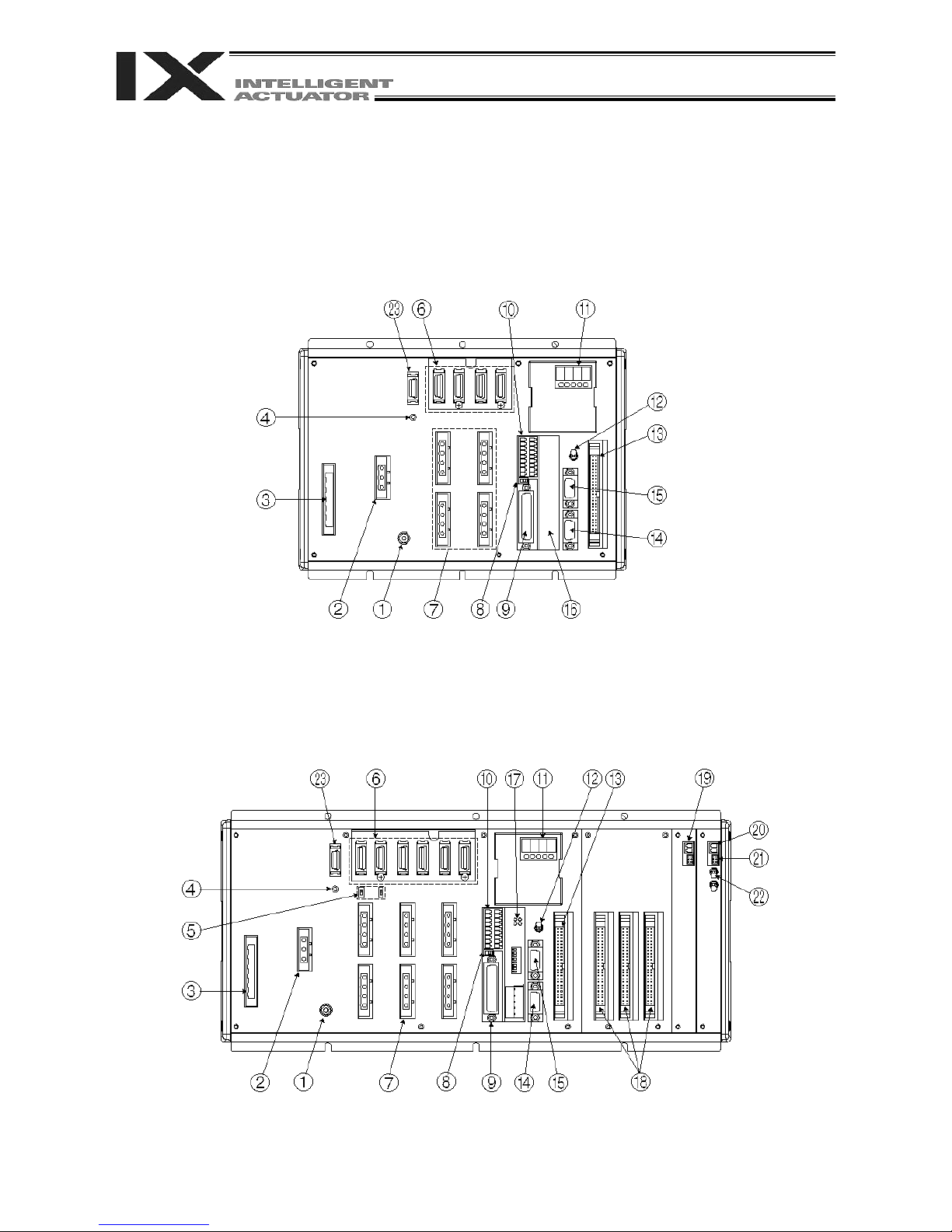
Chapter 4 Name and Function of Each Part
1. Front View of Controller
PX Type (Standard Specification), 4 axes (SCARA axes only)
Part 1 Installation
PX Type (Standard Specification), expanded by 2 additional linear movement axes, with I/O brake
unit
16
16
Page 41

QX Type (Global Specification), 4 axes (SCARA axes only)
Part 1 Installation
QX Type (Global Specification), expanded by 2 additional linear movement axes, with I/O brake unit
17
17
Page 42

Part 1 Installation
[1] FG terminal
[2] External regenerative
unit connector
(Linear movement axis
only)
This terminal is used to ground FG on the enclosure. The enclosure is
connected to PE in the AC input part inside the controller.
FG Terminal Specifications
Item Description
M4 3-point SEMS screw, 5 mm
Name FG
Cable size 2.0 ~ 5.5 mm2 min.
Grounding method Class D grounding
When a linear movement axis decelerates or moves downward, regenerative
energy is produced. The capacitor and resistor in the controller alone may not
be able to absorb this regenerative energy (in which case an “Error No. 60C,
Power-system overhear error” will generate). In this case, connect a
regenerative unit or units.
Whether or not your system needs one or more regenerative units depends on
the specific application such as the configuration of linear movement axes.
Refer to Appendix, “Number of Regenerative Units to be Connected.”
If all axes are SCARA axes, no regenerative unit is required.
External Regenerative Unit Connector Specifications
Item Overview Details
Connector
3-pin 2-piece connector by
Phoenix Contact
GIC2.5/3-STF-7.62
Connector name RB
Size of supplied
cable
1.0 mm2 (equivalent to
AWG17)
The cable is supplied with
the external regenerative
unit.
Connected unit External regenerative box
Terminal
assignments
RB+
Regenerative resistance +
(Motor-driving DC voltage)
RB– Regenerative resistance –
Grounding terminal
18
18
Page 43
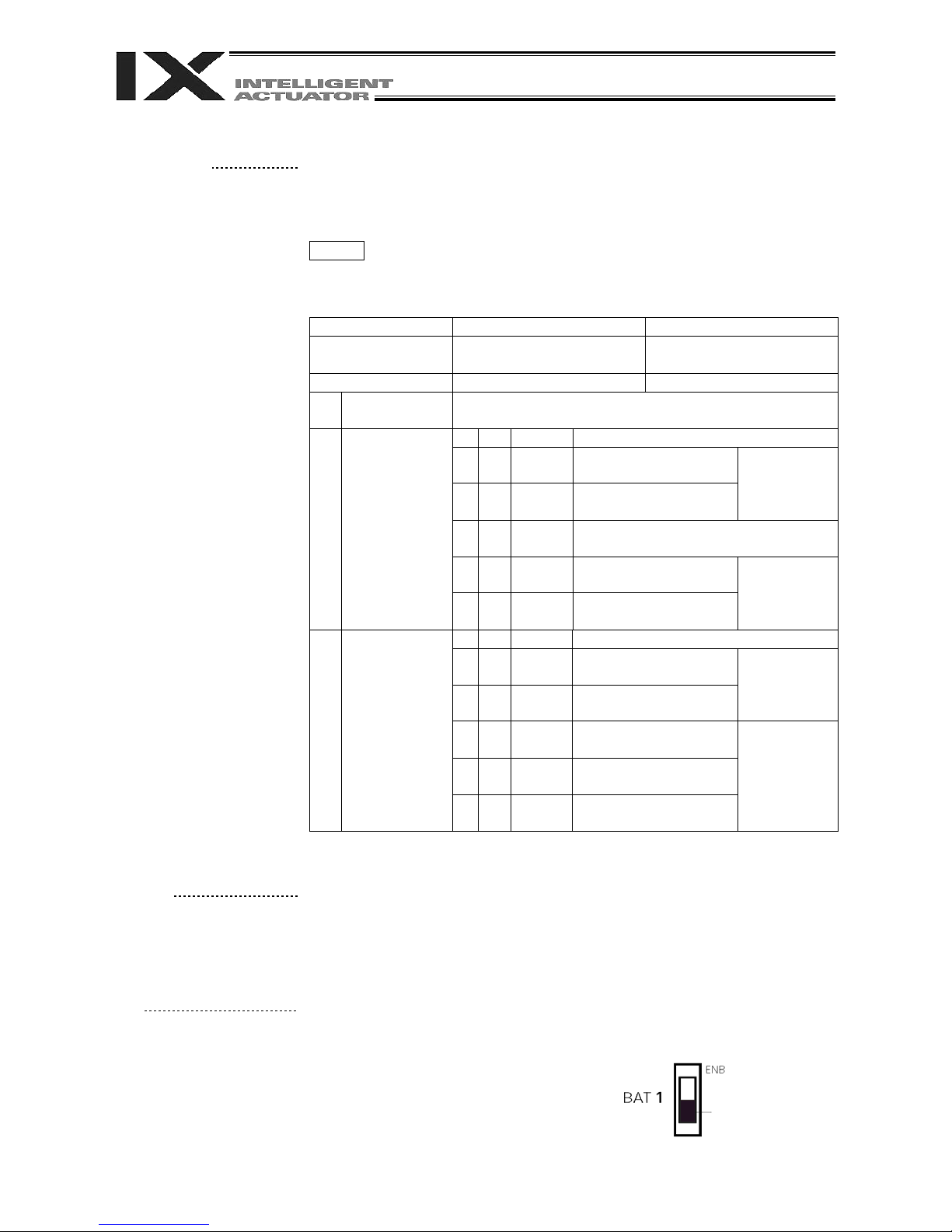
Part 1 Installation
[3] AC-power input
connector
A 200-VAC, single-phase/three-phase input connector consisting of six
terminals including motor power terminals, control power terminals and a PE
terminal.
Note) Select the single-phase input specification or three-phase input
specification, whichever is applicable, for motor drive power.
The standard type only comes with a terminal block.
Caution To prevent electric shock, do not touch this connector when the
controller is receiving power.
snoitacificepS rotcennoC rewoP CA
Item Overview Details
Connector
6-pin 2-piece connector by
Phoenix Contact
GMSTB 2.5/6-7.62
Connector name PWR
Connected
unit
Terminal
assignments
Single-phase specification
Terminal
assignments
Three-phase specification
Single-phase 200/230 VAC power supply, 50/60 Hz
6 PE Protective grounding wire
5 IN CP_L
4 IN CP_N
3 NC
2 IN MP_L
1 IN MP_N
Control power 200
VAC, phase L
Control power 200
VAC, phase N
Cable size
0.75 mm
(AWG18)
Do not connect anything to this
terminal.
Motor power 200
VAC, phase L
Motor power 200
VAC, phase N
Cable size
2
2 mm
(AWG14)
6 PE Protective grounding wire
5 IN CP_L
4 IN CP_N
3 IN MP_R
2 IN MP_S
1 IN MP_T
Control power 200
VAC, phase L
Control power 200
VAC, phase N
Motor power 200
VAC, phase R
Motor power 200
VAC, phase S
Motor power 200
VAC, phase T
Cable size
0.75 mm
(AWG18)
Cable size
2
2 mm
(AWG14)
2
2
[4] Control-power monitor
LED
[5] Absolute-data backup
battery enable/disable
switch (Linear
movement axis only)
A green light illuminates when the control power supply is providing the
correct amount of power.
This switch is used to change the backup operation setting; i.e., whether or
not to back up the encoder using the absolute-encoder backup battery for the
linear movement axis. This function is disabled when the controller is shipped.
After connecting the encoder and axis-sensor cables, turn on the power, and
then set this switch to the top position. This switch is not provided for SCARA
axes.
Set to the bottom
position to disable.
19
19
Page 44
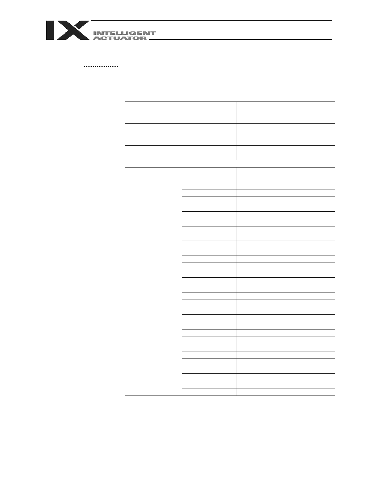
Part 1 Installation
[6] Encoder/axis-sensor
connector
This connector is used to connect the actuator encoder and axis sensors such
as LS, CREEP and OT. * LS, CREEP and OT sensors are optional.
The connectors are assigned to axis 1, axis 2, and so on, from the right.
Encoder/Axis-sensor Connector Specifications
Item Overview Details
Connector
Half-pitch, 26-pin
I/O connector
Cable-end
connector
10226-6202JL (by Sumitomo 3M)
10126-3000VE (by Sumitomo 3M)
(Hood: 10326-52F0-008)
Connector name PG1 ~ 6 Encoder/axis-sensor connector
Maximum wiring
distance
Signal table
30 m
Pin
No.
Signal
name
1
Description
2
3
4
5
6
7 SRD+
8 SRD–
Send/receive differential +
(pulse/magnetic pole switching +)
Send/receive differential -
(pulse/magnetic pole switching -)
9 NC Not connected
10 NC Not connected
11 NC Not connected
12 24VOUT Sensor power output
13 0V 24-V power ground
14 BATT Backup battery
15 BATTGND Battery ground
16 VCC Encoder power
17 GND GND
18 NC Not connected
19 NC Not connected
20 BK–
Brake open output signal - (COM:
Common to all axes)
21 BK+ Brake open output signal +
22 NC Not connected
23 *RSV Sensor input RSV
24 *OT Sensor input OT
25 *CLEEP Sensor input CLEEP
26 *LS Sensor input LS
20
20
Page 45
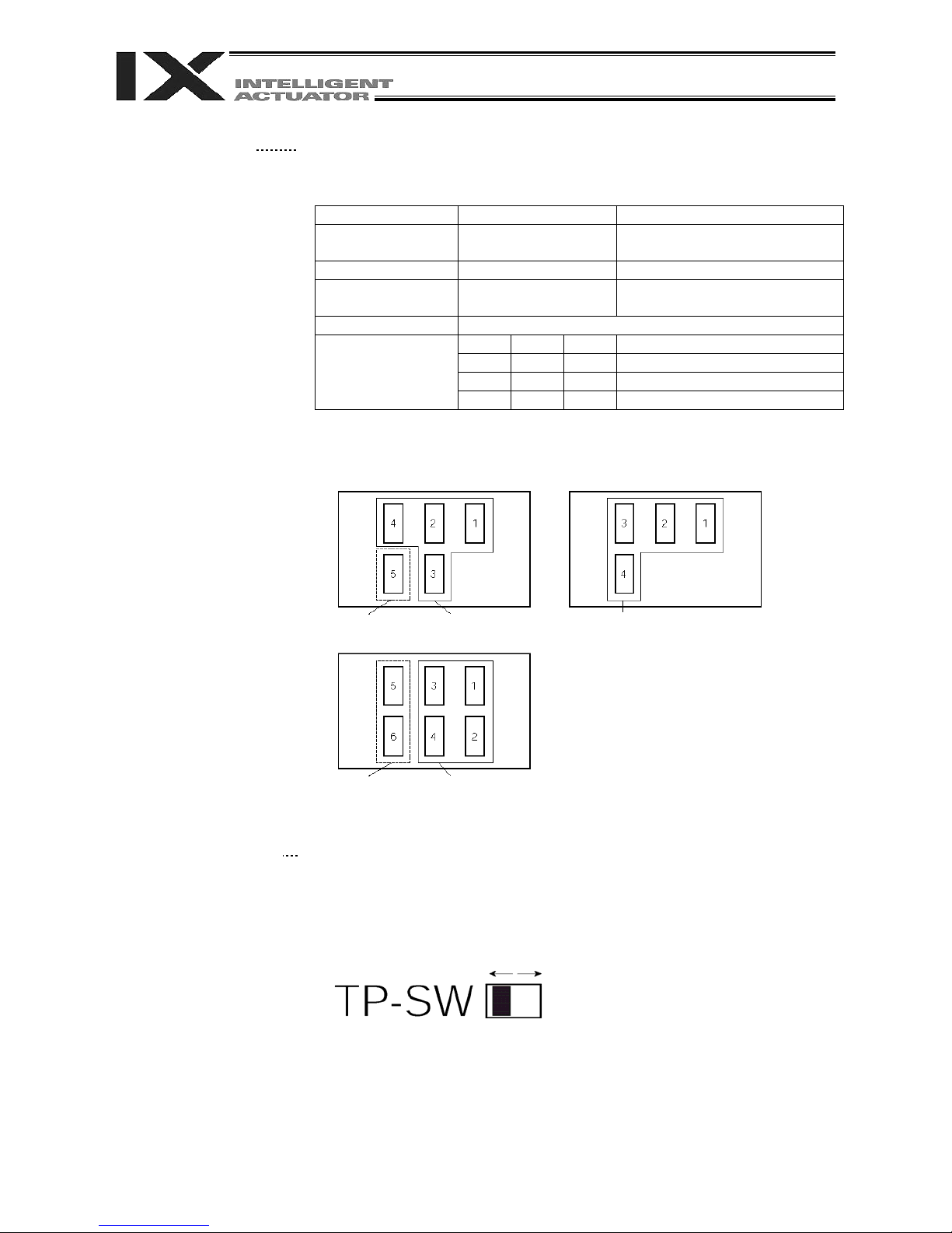
Part 1 Installation
A
A
[7] Motor connector
This connector is used to drive the motor inside the actuator.
Motor Connector Specifications
Item Overview Details
Connector GIC2.5/4-STF-7.62
Connector name M1 to 6 Motor connector
Cable size
0.75 mm
to AWG18)
2
(equivalent
4-pin, 2-piece connector by
Phoenix Contact
Supplied with the actuator.
Connected unit Actuator
Terminal
assignments
1
2
3
4
PE Protective grounding wire
Out U Motor drive phase U
Out V Motor drive phase V
Out W Motor drive phase W
The position of the motor connector for each axis varies depending on the
SCARA type, as shown below.
Arm length 700/800 High-speed type (NSN**----)
dditional linear movement axis SCARA axis
dditional linear movement axis SCARA axis
[8] Teaching-pendant type
switch (P type only)
SCARA axis
Other than the above
This switch is used to change the type of the teaching pendant connected to
the teaching connector [9]. It switches between “IAI’s standard teaching
pedant” and “ANSI teaching pendant.” The switch is located on the front side
of the board. Select the applicable setting in accordance with the teaching
pendant used.
Left: PC cable ( conforming to safety category 4)
SEL-T, SEL-TD, SEL-TG teaching pendant
IA-T-XA teaching pendant
Switch
Right: PC cable
IA-T-X, IA-T-XD
teaching pendant
Note 1: The safety gate switch will not function if this switch is not set
correctly.
Note 2: IAI’s standard teaching pendants cannot be used with Q type
controllers.
Note 3: TP-SW is not available on QX type controllers.
21
21
Page 46

Part 1 Installation
[9] Teaching connector
The teaching interface connects IAI’s teaching pendant or a PC to enable
operation and setting of your equipment from the teaching pendant/PC. The
physical interface consists of a RS232C system based on a 25 pin D-sub
connector. The signal level conforms to RS232C, and a desired baud rate
(up to 115.2 kbps) can be selected depending on the program. RS232C
communication is possible only when the mode switch (12) is set to the
MANU position.
You can also use an ANSI teaching pendant equipped with an ANSIcompliant double-action enable switch. Whether the controller supports an
ANSI teaching pendant or IAI’s standard teaching pendant can be set using
the selector switch (8) provided above the teaching pendant connector. (P
type only)
* With Q-type controllers, connect the supplied dummy plug to the teaching
connector during the AUTO mode.
Interface Specifications of Teaching Serial Interface
Connector DSUB-25 XM3B-2542-502L (by Omron)
Connector name T.P. Teaching connector
Communication
method
Baud rate Up to 115.2 kbps Half-duplex communication speeds of
Maximum wiring
distance
Interface standard RS232C
Connected unit Dedicated teaching
Connection cable Dedicated cable
Power supply 5 VDC or 24 VDC A multi-fuse (MF-R090) is installed to
Protocol X-SEL teaching
Emergency-stop
control
Enabling control Enable switch line (24 V)A line for connecting an enable
[12] Mode switch AUTO/MANU switch Whether or not the teaching pendant
Item Overview Details
RS232C-compliant,
start-stop
synchronous halfduplex communication
10M At 38.4 kbps
pendant
protocol
Series emergencystop relay drive (24 V)
Signal assignments conform to the
RS232C DTE terminal layout. Assign
dedicated control lines to undefined
lines, etc.
up to 115.2 kbps are supported.
IAI’s standard teaching pendant for
X-SEL, or ANSI teaching pendant
protect each line against short
current (the fuse will trip with currents
of between 1.1 A and 2.2 A).
The connector supports the X-SELJ/K teaching pendant interface
protocol.
An emergency-stop relay drive line is
provided in the interface connector.
This line is connected in series with
other emergency-stop contact.
Two independent emergency stop
input circuits are provided as a
redundant safety design.
switch is provided as an operator
interlock. Two independent enable
input circuits are provided as a
redundant safety design.
can be used is set by the
AUTO/MANU mode switch. The
controller establishes a handshake
with the teaching pendant only when
this switch is set to the MANU mode.
Note, however, that the teaching
pendant displays the monitor screen
regardless of the AUTO/MANU
setting.
22
22
Page 47

Part 1 Installation
Interface Specifications of Teaching Serial Interface
Item No. Direction Signal name Details
1 FG Frame ground
2 Out TXD Transmitted data
3 In RXD Received data
4 Out RTS Request to send
5 In CTS Clear to send
6 Out DSR Equipment ready
7 SG Signal ground
8 NC Not connected
9 In RSVTBX1 RSV signal line for generic
teaching pendant
10 In RSVTBX2 RSV signal line for generic
teaching pendant
11 NC Not connected
12 Out EMGOUT1 Emergency stop contact 1
Terminal
assignments
13 In EMGIN1
14 NC Not connected
15 Out RSVVCC 24-V power supply for IA-T-
XA, SEL-T (D) teaching
pendant
16 Out EMGOUT2 Emergency stop contact 2
17 Out ENBVCC1 Enable drive power 1
18 Out VCC Power output
(Power supply for IA-T-X (D)
teaching pendant)
19 In ENBTBX1 Enable input 1
20 In DTR Terminal ready
21 Out ENBVCC2 Enable drive power 2
22 In ENBTBX2 Enable input 2
23 Out EMGS Emergency stop status
24 In EMGIN2 Emergency stop contact 2
25 SG Signal ground
Shading indicates that the signal is used only with an ANSI teaching pendant.
23
23
Page 48
Part 1 Installation
[10] System I/O connector
This I/O connector is used to control the safety actions of the controller.
With the global specification, a safety circuit conforming to a desired safety
category of up to level 4 can be configured using this connector and an
external safety circuit.
System I/O Connector Specifications
Item Overview Details
Connector 2-piece COMBICON
connector (18 pins)
MCD1.5/9-G1-3.5P26THR (by
Phoenix Contact)
Cable end connector FMC1.5/9-ST-3.5
Applicable cable size 0.2 ~ 1.3 mm2 (AWG24-16)
Connector name SYSTEM IO
Connected unit External safety circuit Emergency stop, safety gate,
ready out, external relay cutoff
Overview of Terminal Assignments
Left
Pin
No.
9
8
7
6
5
4
3
2
1
18 DET +24V
Signal
name
Description
DET IN External contact error input
IN Emergency stop detection input
EMGin
EMG1
EMG2
SDN
+24V
line+
line-
line+
line-
Out+
Out-
24 V power output for emergency stop
detection input
Emergency stop switch 1
8 mA (PX type)
Emergency stop switch 2
8 mA (PX type)
External relay drive cutoff contact
output
24 V power output for external contact
error input
17 IN Enable detection input
Right
16
15 line+
14
13 line+
12
11 Out+
10
ENBin
ENB1
ENB2
RDY
+24V
line-
line-
Out-
24 V power output for enable detection
input
Enable switch (safety gate, etc.)
8 mA (PX type)
Enable gate switch 2
8 mA (PX type)
Ready signal contact output
Only a terminal block is supplied without a cable (EMG and ENB are shorted
by a cable). Do not supply power other than from a 24 VDC power supply to
the RDY and SDN contacts.
24
24
Page 49

Part 1 Installation
[11] Panel window
[12] Mode switch
[13] Standard I/O connector
This window consists of a 4-digit, 7 segment LED display and five LED
lamps that indicate the status of the equipment. For the information shown
on the display, refer to 2, “Explanation of Codes Displayed on the Panel
Window” or the “Error Code Table.”
Meanings of Five LEDs
Name Status when the LED is lit
RDY CPU ready (program can be run)
ALM CPU alarm (system down level error), CPU hardware error
EMG
Emergency stop has been actuated, CPU hardware error, power
system hardware error
PSE Power system hardware error
CLK System clock error
This alternate switch with lock is used to command a controller operation
mode. To operate the switch, pull it toward you and tilt.
Tilting the switch upward will select MANU (manual mode), while tilting it
downward will select AUTO (auto mode). Teaching can be performed only in
the MANU mode, but auto program start is not enabled in the MANU mode.
* If you are using a QX type controller, connect the supplied dummy plug to
the teaching connector [9] during the AUTO mode.
This connector consists of a 50 pin flat connector and comprises 32 input
output DIOs.
/16
Overview of Standard I/O Interface Specifications
Item Description
Connector name I/O
Connector Flat connector, 50 pin
Power supply Supplied from connector pin Nos. 1 and 50
Input 32 points (including general purpose and dedicated
inputs)
Output 16 points (including general purpose and dedicated
outputs)
Connected to External PLC, sensor, etc.
25
25
Page 50

Part 1 Installation
I/O Interface List
Pin No. Category Port No. Function Cable color
1 - +24 V input Brown-1
The functions are at the time
of shipment. The functions
assigned to port Nos. 000 to
015, 300 to 310, 313 and
314 can be changed via I/O
parameters. (Refer to Nos.
30 to 56, No. 59 and 60 in 1,
“I/O Parameters,” of
Appendix, “List of
Parameters.”)
2 000 Program start Red-1
3 001 General purpose input Orange-1
4 002 General purpose input Yellow-1
5 003 General purpose input Green-1
6 004 General purpose input Blue-1
7 005 General purpose input Purple-1
8 006 General purpose input Gray-1
9 007 Program specification (PRG No. 1) White-1
10 008 Program specification (PRG No. 2) Black-1
11 009 Program specification (PRG No. 4) Brown-2
12 010 Program specification (PRG No. 8) Red-2
13 011 Program specification (PRG No.
Orange-2
10)
14 012 Program specification (PRG No.
Yellow-2
20)
15 013 Program specification (PRG No.
Green-2
40)
16 014 General purpose input Blue-2
Input
17 015 General purpose input Purple-2
18 016 General purpose input Gray-2
19 017 General purpose input White-2
20 018 General purpose input Black-2
21 019 General purpose input Brown-3
22 020 General purpose input Red-3
23 021 General purpose input Orange-3
24 022 General purpose input Yellow-3
25 023 General purpose input Green-3
26 024 General purpose input Blue-3
27 025 General purpose input Purple-3
28 026 General purpose input Gray-3
29 027 General purpose input White-3
30 028 General purpose input Black-3
31 029 General purpose input Brown-4
32 030 General purpose input Red-4
33
031 General purpose input Orange-4
34 300 Alarm output Yellow-4
35 301 Ready output Green-4
36 302 Emergency stop output Blue-4
37 303 General purpose output Purple-4
38 304 General purpose output Gray-4
39 305 General purpose output White-4
40 306 General purpose output Black-4
41 307 General purpose output Brown-5
42 308 General purpose output Red-5
43 309 General purpose output Orange-5
Output
44 310 General purpose output Yellow-5
45 311 General purpose output Green-5
46 312 General purpose output Blue-5
47 313 Alarm output for low system-
Purple-5
memory backup battery voltage
48 314 Alarm output for low absolute-
Gray-5
encoder backup battery voltage
49
315 General purpose output White-5
50 - 0V Black-5
26
26
Page 51

Part 1 Installation
[14] General RS232C port
connector 1
[15] General RS232C port
connector 2
Channel 1 of the two-channel RS232C port provided for connection of
general RS232C equipment.
(Refer to I/O parameter Nos. 201 to 203.)
Channel 2 of the two-channel RS232C port provided for connection of
general RS232C equipment.
(Refer to I/O parameter Nos. 213 to 215.)
General RS232C Connector Specifications
Item Overview Details
Connector D-sub, 9 pin (DTE) XM2C-0942-502L (OMRON)
Connector name S1/S2
Maximum wiring
10 M At 38400 bps
distance
Interface standard RS232C
Connected unit AT-compatible PC,
Half-duplex communication
etc.
Connection cable PC-AT standard 232C cross-
cable
Terminal
assignments
1
2
3
4
5
6
7
In (CD) (Carrier detection: Not used)
In RD Received data (RXD)
Out SD Transmitted data (TXD)
Out ER Equipment ready (DTR)
In SG Signal ground
In DR Data set ready (DSR)
Out (RS) (Request to send (RTS): Not
used)
8
9
In (CS) (Clear to send (CTS): Not used)
NC Not used
Use a cross-cable to connect to the RS232C port of a PC.
[16] Installation position of
field network board
[17] Optional board
[18] Expansion I/O board
(optional)
This is where a Fieldbus interface module is installed. In this example, this
position is left unoccupied (no module is installed).
An optional field network board is installed. A DeviceNet board is installed in
this example.
Optional expansion I/O boards are installed in the example.
27
27
Page 52

Part 1 Installation
[19] Brake power input
connector
(SCARA axis only)
[20] Brake power input
connector
This connector is used to input the power for SCARA brake control. 24 VDC
must be supplied externally.
Connect the SCARA-axis brake power to both the brake power cable from
the SCARA robot and this connector.
A power input connector for driving the brake of a linear axis, high-speed
SCARA robot (NSN**…) or actuator with an arm length of 700 or 800.
24 VDC must be supplied externally. If the specified power is not supplied,
the actuator brake cannot be released. Be sure to supply the power to this
connector if you are using a high-speed SCARA robot (NSN**…), actuator
with an arm length of 700 or 800 or linear axis with brake.
As for the brake power cable, use a shielded cable and connect the shield
on the 24-V power-supply side. The bottom side of the connector connects
to +24 V.
Brake Power Connector Specifications
Item Overview Details
Connector Phoenix Contact MC1.5/2-G-3.5
Cable-end
connector
Phoenix Contact MC1.5/2-ST-3.5
Applicable cable size: 0.1 ~ 2.0
2
(AWG28-14)
mm
Connector name BK PWR
Input voltage
24 VDC 10%
0 V 24 V power ground Terminal
assignments
+24 V 24 V power input
[21] Brake release switch
connector (Linear
movement axis only)
This connector accepts a switch that releases the brake of a linear
movement axis externally from the controller.
Shorting the COM and BKRMT* terminals of this connector will release the
brake.
Use this connector if you want to operate the linear movement axis manually
in the event of a power failure or error in the controller.
Brake-release Switch Connector Specifications
Item Overview Details
Connector Hirose DF11-6DP-2DS (*)
Connector name BK RMT
Connected unit Brake-release switch
Terminal
assignments
BKRMT5 Brake release switch input for
1
axis 5
BKRMT6 Brake release switch input for
2
axis 6
3
4
COM (COM) Switch input common
5
COM (COM) Switch input common
6
*) Mating connector --- Hirose socket: DF11-6DS-2C, crimp terminal: DF11-
2428SC
28
28
Page 53

Part 1 Installation
[22] Brake switch (Linear
movement axis only)
[23] Conveyor tracking
connector
This alternate switch with lock is used to release the axis brake. To operate
the switch, pull it toward you and tilt. Tilting the switch upward (RLS side) will
release the brake forcibly, while tilting it downward (NOM) will enable the
controller to release the brake.
Note: The SCARA-axis brake switch is located on the panel of the SCARA
robot.
This connector is used only when the controller is of conveyor tracking
specification.
Normally this connector is not used.
29
29
Page 54

Part 1 Installation
2. Explanation of Codes Displayed on the Panel Window
2.1 Application
Display Priority (*1) Description
1
1 System down level error
2 Writing data to the flash ROM.
3 Emergency stop is being actuated (except during the update mode).
4 Enable switch (deadman switch/safety gate) OFF (except in the update mode)
5 Cold start level error
5 Cold start level error
5 Operation cancellation level error
5 Operation cancellation level error
AC power is cut off (including momentary power failure or drop in power
source voltage).
6 Waiting for a drive source cutoff reset input (except during the update mode).
6
Operation is paused and waiting for a restart signal (except during the update
mode)
7 All servo axes are interlocked (except during the update mode)
8 Message level error
8 Message level error
9 Core update mode
9 Core update is in progress
9 Core update has completed
9 Slave update mode
9 Slave update is in progress
9 Slave update has completed
9
9
A program is running (last started program). *** indicates the program number.
(Controller with increased memory size (with gateway function))
A program is running (last started program). ** indicates the program number.
(Controller with increased memory size)
9 Initialization sequence number
9 Debug mode
9 Ready status (auto mode)
9 Ready status (manual mode)
30
30
(*1) The priority increases as the number decreases.
Page 55

2.2 Core
Display Priority (*1) Description
1
1 Coldstart level error
1 Coldstart level error
1 Operationcancellation level error
1 Operationcancellation level error
2 Message level error
2 Message level error
2 Application update mode
2 Application update is in progress
2 Application update has completed
AC power is cut off (including momentary power failure or drop in power
source voltage)
Part 1 Installation
2 Hardware test mode process
2 Clearing the application flash ROM
2 Application flash ROM has been cleared
2 Jump to the application
2 Core flash ROM check process
2 Application flash ROM check process
2 SDRAM check process
(*1) The priority increases as the number decreases.
31
31
Page 56

Part 1 Installation
2.3 Current Monitor and Variable Monitor
Other parameter Nos. 49 and 50 can be set up to monitor currents or variables on the panel window.
(1) Current monitor
Currents of up to four axes having continuous axis numbers can be monitored.
Parameter settings
Other parameter No. 49 = 1
Other parameter No. 50 = Smallest axis number among the axes to be monitored
Example) If other parameter No. 49 is set to “1” and other parameter No. 50 to “3” for a 6 axis controller,
the far right segment digit will show the current for axis 3.
Axis 6 Axis 5 Axis 4 Axis 3
When data is written to the flash ROM or a software reset (restart) is executed after the
parameter values have been input, the panel window will show the motor current to rating ratio
(%) by a segment pattern, instead of “ready status” or “program run number.”
The segment display patterns and corresponding motor current to rating ratios (%) are shown
below.
0 < Motor current to rating ratio
(%) 25
25 < Motor current to rating ratio
(%) 50
50 < Motor current to rating ratio
(%) 75
75 < Motor current to rating ratio
(%) 100
Thick lines indicate illuminated segments.
100 < Motor current to rating ratio
(%) 150
150 < Motor current to rating ratio
(%) 200
200 < Motor current to rating ratio
(%)
32
32
Page 57

Part 1 Installation
(2) Variable monitor
The contents of global integer variables can be displayed on the panel window.
Positive integers of 1 to 999 can be displayed.
Parameter settings
Other parameter No. 49 = 2
Other parameter No. 50 = Variable number of the global integer variable to be monitored
When data is written to the flash ROM or a software reset (restart) is executed after the parameter values
have been input, the panel window will show the content of the global integer variable, instead of “ready
status” or “program run number.” The far-left segment digit should read “U.”
Display example)
33
33
Page 58

Part 1 Installation
Chapter 5 Specifications
1. Controller Specifications
1.1. PX Type (Standard Specification)
1-axis to 6-axis controller
Total output when
maximum number of axes
are connected
Control power input
Motor power input Single-phase specification: 200 to
Power source frequency 50/60 Hz
Insulation resistance
Withstand voltage 1500 VAC for 1 minute
Surrounding air
temperature range
Surrounding humidity range 10% to 95% (Non-condensing; conforming to JIS C3502 RH-2)
Storage temperature range
Protection class IP20
Drive-source cutoff method Internal relay
Emergency stop input Contact B input (Internal power-supply type)
Emergency stop action Deceleration stop + Regenerative brake by timer (failsafe)
Enable input Contact B input (Internal power-supply type)
System ready output No voltage contact (relay) output; for generation of equipment ready signal
Axis control method AC full digital servo
Position detection methods 17 bit incremental encoder (Wire-saving type)
Batteries Absolute-data backup battery: AB-5 made by IAI
Speed setting 1 mm/sec to 3000 mm/sec (Varies according to the applicable model.)
Acceleration/deceleration
setting
Programming language Super SEL language
Program steps
Number of positions
Single-phase specification: 1600 W Three-phase specification: 2400 W
Single phase, 200 to 230 VAC 10%
Three-phase specification: 200 to
230 VAC 10%
10 M min. (measured at 500 VDC between the power terminal and I/O
terminals and between the external terminals and case)
0 to 40C
-25C to 70C (Excluding the battery)
based on the wired-OR logic among multiple equipment. Max. 500 mA (24
VDC).
17 bit rotation data backup absolute encoder
Resolution: 14 bits under both methods (16384 pulses)
System-memory backup battery: CR2032
0.01 G to 3 G (Varies according to the applicable model.)
Controller with
increased memory size
(with gateway function)
Controller without
increased memory size
Controller with
increased memory size
(with gateway function)
Controller without
increased memory size
Note 1)
9999 steps (total)
6000 steps (total)
20000 positions (total)
Position Nos. 1 to 10000 can be saved to the
battery backup memory.
Position Nos. 10001 to 20000 can be saved to
the flash memory.
4000 positions (total)
All position data can be saved to the battery
backup memory.
230 VAC 10%
34
34
Page 59

Part 1 Installation
Number of programs
Controller with
increased memory size
128 programs
(with gateway function)
Controller without
increased memory size
64 programs
Multi-tasking 16 programs
Storage device Flash ROM + SRAM battery backup
Data input methods Teaching pendant or PC software
Absolute brake unit (brake
type or absolute
specification actuator only)
Built-in brake drive circuit
Driven by over-excitation at 90 V, released at 45 V (steady state)
There are no limitation on the number of brake axes (A 5/6-axis system
with brake can be supported.)
Protective functions Motor overcurrent, overload, motor driver temperature check, overload
check, encoder open detection.
Regenerative resistance
Built-in (1 k, 20 W); expandable by external unit
Accessory I/O flat cable
Standard inputs 32 points or 16 points, NPN or PNP (set before shipment)
Standard outputs 16 points or 32 points, NPN or PNP (set before shipment)
RS232C port for teaching
serial interface
Enabled only in the manual operation mode.
IAI’s dedicated teaching pendant or ANSI teaching pendant (selected by a
switch)
RS232C port for general
PC connection
Expanded inputs/outputs
Dedicated 2 channel RS232C, 9 pin DTE specification
Half-duplex at speeds up to 115.2 kbps (1 channel) or up to 76.8 kbps
(simultaneous communication with 2 channels)
Note 3)
Expandable to 3 slots
(optional)
Fieldbus interface (optional) Profibus-DP (IN: 32 bytes max./OUT: 32 bytes max.)
DeviceNet (IN: 32 bytes max./OUT: 32 bytes max.)
CC-Link (IN: 32 bytes max./OUT: 32 bytes max.)
Ethernet interface (optional) Packet communication (client-server communication) by TCP/IP using SEL
language
X-SEL PC software connection
MODBUS/TCP remote I/O (IN: 32 bytes max./OUT: 32 bytes max.)
Note 1) The withstand voltage of the actuator motor is 1000 V for 1 minute.
When performing a withstand voltage test with the controller and actuator connected, make sure the test
voltage and duration will not exceed 1000 V and 1 minute, respectively.
Note 2) If one RS232C channel is used at a communication speed of 115.2 kbps, use the other channel at 38.4
kbps or below. If these speeds are exceeded, an overrun error or other problems will occur and successful
communication cannot be guaranteed.
* RCS2-R**7, LS and LSA-series actuators cannot be connected as axis 5 or 6.
35
35
Page 60

Part 1 Installation
1.2 QX Type (Global Specification)
1-axis to 6-axis controller
Total output when
maximum number of axes
are connected
Control power input
Motor power input Single-phase specification: 200 to
Power source frequency 50/60 Hz
Insulation resistance
Withstand voltage 1500 VAC for 1 minute
Surrounding air
temperature range
Surrounding humidity range 10% to 95% (Non-condensing; conforming to JIS C3502 RH-2)
Storage temperature range
Protection class IP20
Drive-power cutoff method External safety circuit
Emergency stop input Contact B input (Internal power-supply type, redundant)
Emergency stop action Deceleration stop + Regenerative brake by timer (failsafe)
Enable input Contact B input (Internal power-supply type)
System ready output No voltage contact (relay) output; for generation of equipment ready signal
Axis control method AC full digital servo
Position detection methods 17 bit incremental encoder (Wire-saving type)
Batteries Absolute-data backup battery: AB-5 made by IAI
Speed setting 1 mm/sec to 3000 mm/sec (Varies according to the applicable model.)
Acceleration/deceleration
setting
Programming language Super SEL language
Program steps
Number of positions
Number of programs
Multi-tasking 16 programs
Storage device Flash ROM + SRAM battery backup
Single-phase specification: 1600 W Three-phase specification: 2400 W
Single phase, 200 to 230 VAC 10%
Three-phase specification: 200 to
230 VAC 10%
230 VAC 10%
10 M min. (measured at 500 VDC between the power terminal and I/O
terminals and between the external terminals (together) and case)
Note 1)
0 to 40C
-25C to 70C (Excluding the battery)
based on the wired-OR logic among multiple equipment. Max. 500 mA (24
VDC).
17 bit rotation data backup absolute encoder
Resolution: 14 bits under both methods (16384 pulses)
System-memory backup battery: CR2032
0.01 G to 3 G (Varies according to the applicable model.)
Controller with
increased memory size
9999 steps (total)
(with gateway function)
Controller without
increased memory size
Controller with
increased memory size
(with gateway function)
6000 steps (total)
20000 positions (total)
Position Nos. 1 to 10000 can be saved to the
battery backup memory.
Position Nos. 10001 to 20000 can be saved to
the flash memory.
Controller without
increased memory size
4000 positions (total)
All position data can be saved to the flash
memory.
Controller with
increased memory size
128 programs
(with gateway function)
Controller without
increased memory size
64 programs
36
36
Page 61

Part 1 Installation
Data input methods Teaching pendant or PC software
Absolute brake unit (brake
type or absolute
specification actuator only)
Built-in brake drive circuit
Driven by over-excitation at 90 V, released at 45 V (steady state)
There are no limitation on the number of brake axes (A 6-axis system with
all axes equipped with a brake can be supported.)
Protective functions Motor overcurrent, overload, motor driver temperature check, overload
check, encoder open detection
Regenerative resistance
Built-in (1 k, 20 W); expandable by external unit
Accessory I/O flat cable
Standard inputs 32 points or 16 points, NPN or PNP (set before shipment)
Standard outputs 16 points or 32 points, NPN or PNP (set before shipment)
RS232C port for teaching
serial interface
Enabled only in the manual operation mode.
IAI’s dedicated teaching pendant or ANSI teaching pendant (selected by a
switch)
RS232C port for general
PC connection
Expanded inputs/outputs
Dedicated 2 channel RS232C, 9 pin DTE specification
Half-duplex at speeds up to 115.2 kbps (1 channel) or up to 76.8 kbps
(simultaneous communication with 2 channels)
Note 3)
Expandable to 3 slots
(optional)
Fieldbus interface (optional) Profibus-DP (IN: 32 bytes max./OUT: 32 bytes max.)
DeviceNet (IN: 32 bytes max./OUT: 32 bytes max.)
CC-Link (IN: 32 bytes max./OUT: 32 bytes max.)
Ethernet interface (optional) Packet communication (client-server communication) by TCP/IP using SEL
language
X-SEL PC software connection
MODBUS/TCP remote I/O (IN: 32 bytes max./OUT: 32 bytes max.)
Note 1) The voltage protection rating of the actuator motor is 1000 V for 1 minute.
When performing a voltage test with the controller and actuator connected, make sure the test voltage and
duration will not exceed 1000 V and 1 minute, respectively.
Note 2) If one RS232C channel is used at a communication speed of 115.2 kbps, use the other channel at 38.4
kbps or below. If these speeds are exceeded, an overrun error or other problems will occur and successful
communication cannot be guaranteed.
* RCS2-R**7, LS and LSA-series actuators cannot be connected as axis 5 or 6.
1.3 Differences between QX Type (Global Specification) and PX Type (Standard Specification)
Users require different safety categories in accordance with the overall configuration of their equipment.
The QX type (global specification) controller has no built-in drive source cutoff circuit so that the user can
design their equipment to a desired safety category. The PX type (standard specification) controller has a
built-in circuit for cutting off the drive source inside the controller using a relay. The differences between
these two specifications are summarized below. Items not specified in the table are basically the same
between the two specifications.
Differences between Global Specification and Standard Specification
Item QX type (global specification) PX type (standard specification)
Power input part Motor power supply and control power supply are separated.
Safety circuit configuration Redundant circuits are supported
Drive source cutoff circuit Installed externally. Built-in motor power cutoff relay
Highest safety category
supported
Safety category 4 (The user is responsible
for demonstrating conformance)
System I/O connector 18 pin, 2 row/2 piece connector by Phoenix Contact
ANSI TP Supported (redundant safety circuits)
TP: Teaching pendant
Redundant circuits are not
supported.
Safety category B
Supported (redundant safety
circuits are not supported)
37
37
Page 62

2. External I/O Specifications
2.1. NPN Specification
(1) Input part
External Input Specifications (NPN Specification)
Item Specification
Input voltage
Input current 7 mA per circuit
ON/OFF voltage
Insulation method Photocoupler insulation
External devices
24 VDC 10%
ON voltage --- 16.0 VDC min.
OFF voltage --- 5.0 VDC max.
[1] No voltage contact (minimum load of approximately 5 VDC/1 mA)
[2] Photoelectric/proximity sensor (NPN type)
[3] Sequencer transistor output (open-collector type)
[4] Sequencer contact output (minimum load of approximately 5 VDC/1
mA)
Part 1 Installation
[Input circuit]
560
P24*
+
External power supply
24 VDC 10%
-
Internal circuit
3.3 k
Input terminal
* P24: I/O interface pin No. 1
Caution
If a non-contact circuit is connected externally, malfunction may result from leakage
current. Use a circuit in which leakage current in a switch-off state does not exceed 1
mA.
X-SEL controller’s input signal
ON duration
At the default settings, the system recognizes the ON/OFF durations of input signals if they
are approximately 4 msec or longer. The ON/OFF duration settings can also be changed
using I/O parameter No. 20 (input filtering frequency).
38
38
OFF duration
Page 63

Part 1 Installation
(2) Output part
External Output Specifications (NPN Specification)
Item Specification
Load voltage 24 VDC
Maximum load current 100 mA per point, 400 mA per 8 ports Note)
Leakage current 0.1 mA max. per point
Insulation method Photocoupler insulation
External devices
Note) 400 mA is the maximum total load current of every eight ports from output port No. 300 (the maximum total
load current of output port No. 300 + n to No. 300 + n + 7 is 400 mA, where n is 0 or a multiple of 8).
[1] Miniature relay
[2] Sequencer input unit
TD62084 (or equivalent)
[Output circuit]
P24*
Surge absorber
Load
Internal circuit
Output terminal
External power supply
24 VDC 10%
-
N*
* P24: I/O interface pin No. 1
* N: I/O interface pin No. 50
Caution
In the event that the load is short-circuited, the overcurrent protection circuit will cut the
power. However, give due consideration to the circuit connection layout to prevent a
short-circuit or overcurrent.
39
39
Page 64
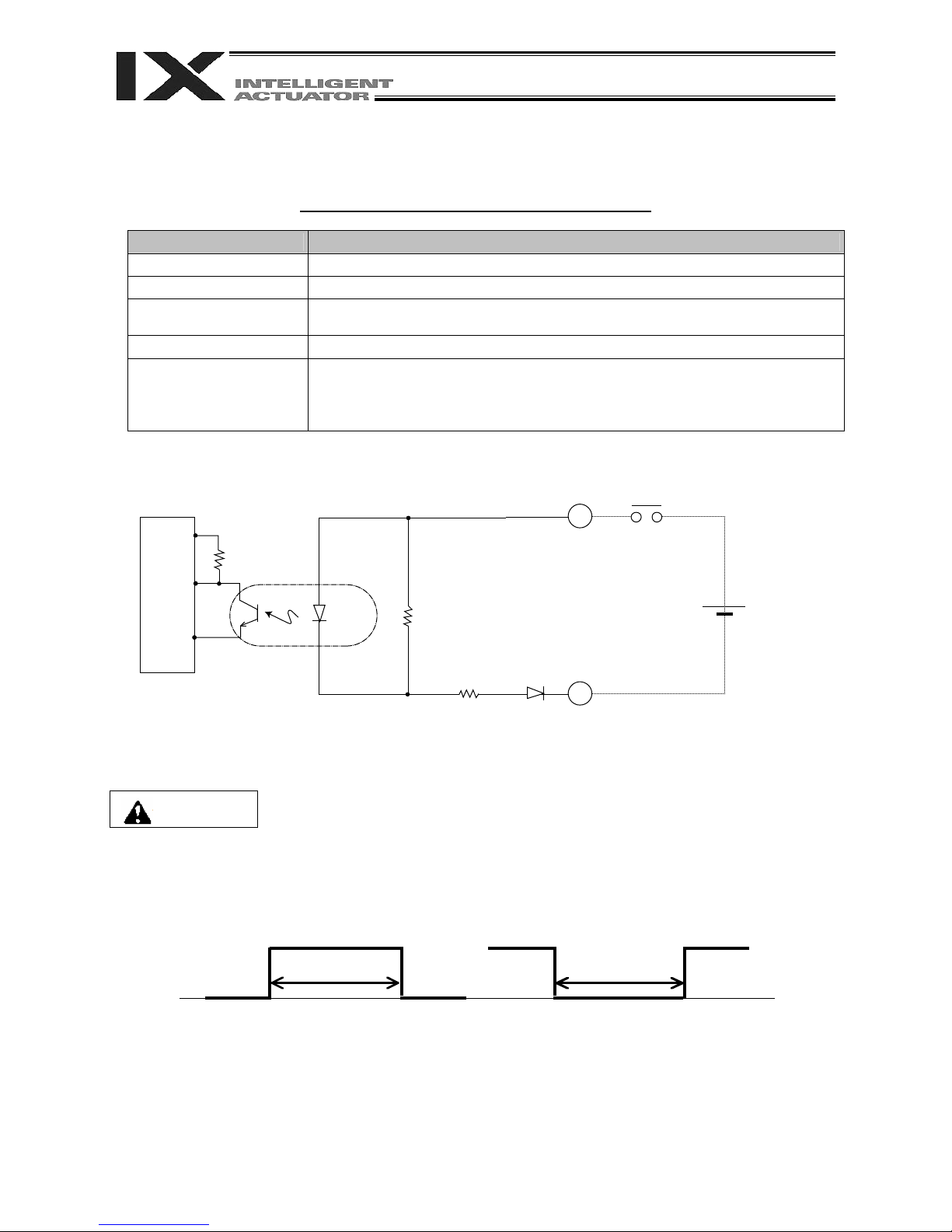
2.2. PNP Specification
(1) Input part
External Input Specifications (PNP Specification)
Item Specification
Input voltage
Input current 7 mA per circuit
ON/OFF voltage
Insulation method Photocoupler insulation
External devices
24 VDC 10%
ON voltage --- 8 VDC max.
OFF voltage --- 19 VDC min.
[1] No-voltage contact (minimum load of approx. 5 VDC/1 mA)
[2] Photoelectric/proximity sensor (PNP type)
[3] Sequencer transistor output (open-collector type)
[4] Sequencer contact output (minimum load of approx. 5 VDC/1 mA)
Part 1 Installation
[Input circuit]
Input terminal
External power
+
560
supply 24 VDC 10%
-
Internal circuit
3.3 K
N*
* N: I/O interface pin No. 50
Caution
If a non-contact circuit is connected externally, malfunction may result from leakage
current. Use a circuit in which leakage current does not exceed 1 mA.
X-SEL controller’s input signal
ON duration
At the default settings, the system recognizes the ON/OFF durations of input signals if they
are approximately 4 msec or longer. The ON/OFF duration settings can also be changed
using I/O parameter No. 20 (input filtering frequency).
OFF duration
40
40
Page 65
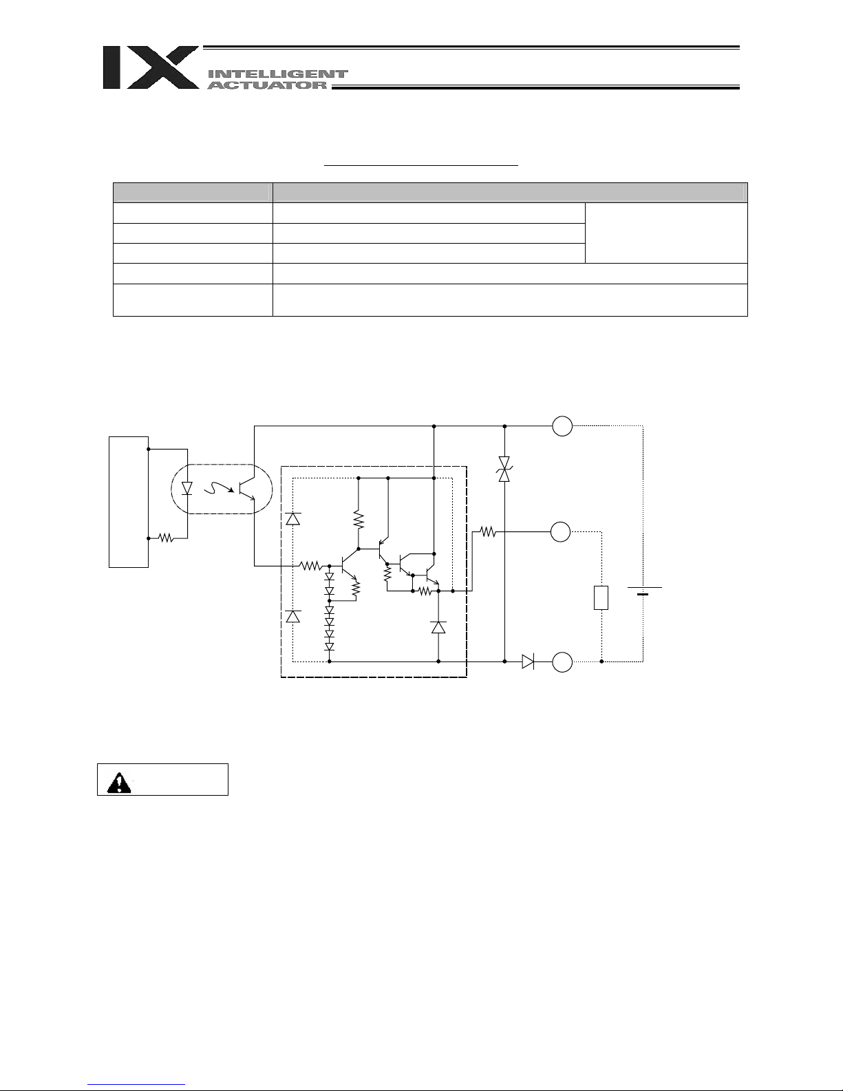
Part 1 Installation
(2) Output part
External Output Specifications
Item Specification
Load voltage 24 VDC
Maximum load current 100 mA per point, 400 mA per 8 ports Note)
Leakage current 0.1 mA max. per point
Insulation method Photocoupler insulation
External devices
Note) 400 mA is the maximum total load current of every eight ports from output port No. 300 (the maximum total
load current of output port No. 300 + n to No. 300 + n + 7 is 400 mA, where n is 0 or a multiple of 8).
[1] Miniature relay
[2] Sequencer input unit
TD62784 (or equivalent)
Internal circuit
Caution
[Output circuit]
10
* P24: I/O interface pin No. 1
* N: I/O interface pin No. 50
P24
Surge absorber
Output terminal
Load
N
+
External power supply
24 VDC 10%
-
In the event that the load is short-circuited, the overcurrent protection circuit will cut the
power. However, give due consideration to the circuit connection layout to prevent a
short-circuit or overcurrent.
41
41
Page 66
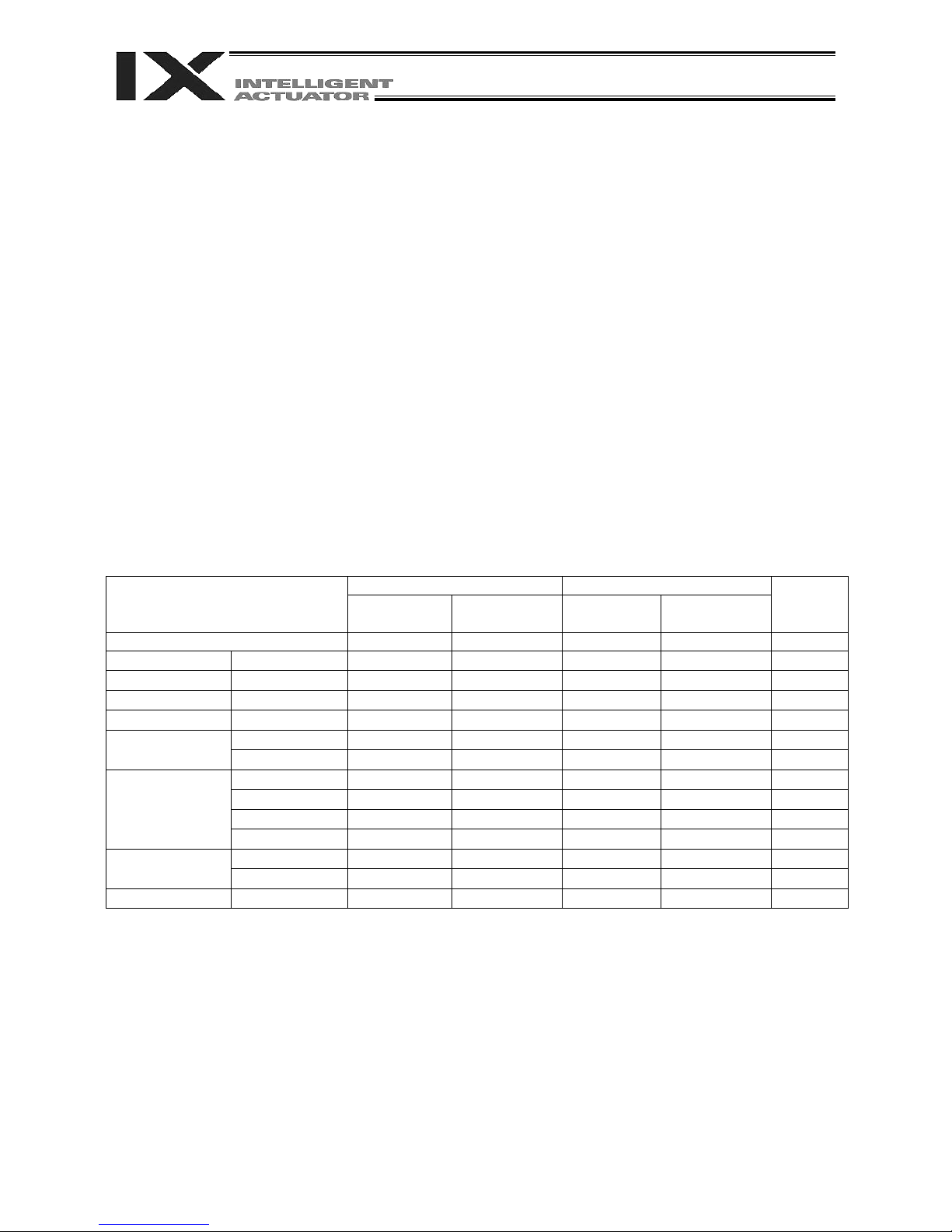
Part 1 Installation
3. Power Source Capacity and Heat Output
The power consumption and heat output of the X-SEL controller will vary depending on the number of
connected axes and I/O configuration. This section explains how to estimate the power source capacity
and heat output of your X-SEL controller.
The X-SEL controller requires the following power supplies:
A. Control power
Power to the logic control part of the controller. Single-phase 200 VAC must be supplied.
B. Motor power
Power for driving the actuator. Three-phase (single-phase) 200 VAC must be supplied.
* The single-phase power specification is applicable only to single-phase controllers.
C. I/O power
If a DIO card is installed in an I/O slot, 24 VDC must be supplied.
D. Brake power
24 VDC must be supplied only when a brake type actuator is driven.
(1) Power source capacity and heat output of the control part
The control part consists of the standard units connected to every controller and optional units such as an
I/O card. Therefore, the power consumption and heat output of the control part will vary depending on the
system configuration.
Additionally, heat outputs from the units operated by an external power source must also be considered.
The table below lists the power consumption of various controller units.
List of Power Consumptions of teh Control Part
Control power supply External power source
Internal
consumption
External
consumption
Internal
consumption
External
consumption
Base part 13.19 W 1
Driver *1 Per board 2.63 W
Encoder Per axis 1 W 1.5 W
Fan unit *2 Per fan 2.4 W
Axis sensor Per axis 1.92 W
DIO card
DIO (48 points) 2.5 W 6.1 W
DIO (96 points) 3.5 W 11.26 W
DeviceNet 1 W 0.72 W
Network module
CC-Link 1 W 0.5 W
Profibus-DP 1.75 W
Ethernet 2.25 W
Teaching
pendant
IAI standard 1.5 W
ANSI 4.08 W
Brake *3 Per axis 2.5 W 5.8 W
*1 One 750 or 600-W SCARA axis occupies one board.
With actuators of 400 W or below, two axes occupy one board.
Quantity
1 3
2 6
4 6
0 2
0 4
0 4
0 1
0 1
0 1
0 1
0 1
0 1
0 4
42
42
Page 67

Part 1 Installation
*2 The number of fan units varies depending on the controller specification.
The number of fan units varies as follows in accordance with the number of controller axes (whether or
not linear movement axis is added) and use/no-use of any expansion I/O board.
Controller Specifications and Number of Fan Units
PX QX
SCARA axes only
(without linear
movement axis)
5/6-axis
specification (with
linear movement
axis)
Without expansion
I/O board
With expansion I/O
board
Without expansion
I/O board
With expansion I/O
board
4 3
5 4
5 4
6 5
*3 For a SCARA robot with an arm length of 500 mm or more, two axes come with a brake.
For a SCARA robot with an arm length of 250 to 350 mm, one axis comes with a brake.
For a SCARA robot with an arm length of 120 or 150 mm, a brake is optional.
(If the system has a linear movement axis with brake, this brake is provided in addition to the brake(s)
for the SCARA axis(es).)
[1] Control power source capacity
The power source capacity of the control power supply is obtained by applying the efficiency
coefficient and power factor to the sum of all power consumptions of controlled units, based on the
applicable values shown in the table.
Control power source capacity [VA] = (Power consumption of each controlled unit x Quantity)
0.7 (Efficiency coefficient) 0.6 (Power factor)
[2] Heat output of the control system
The heat output of the controller’s control system is obtained as the total sum of all internal power
consumptions of controlled units and internal power consumptions of external power sources, based
on the applicable values shown in the table.
Heat output from control system [W] =
(Internal power consumption of each controlled unit x Quantity) + (Internal power
consumption of each external power source x Quantity).
[3] I/O power-source capacity
The I/O power source capacity (24 VDC) is obtained as the total sum of all power consumptions of
external power sources for DIO cards.
I/O power source capacity [W] =
(Internal power consumption of each external power source for DIO x Quantity)
[4] Brake power source capacity
The brake power source capacity (24 VDC) is obtained as the total sum of all power consumptions of
external power sources for brakes.
Brake power source capacity [W] =
(Power consumption of each external power source for brake x Quantity)
43
43
Page 68

Part 1 Installation
(2) Power consumption and heat output of the motor drive part
Both the power consumption and heat output of the motor drive part will vary depending on the number of
axes connected to the controller and wattage configuration. The table below lists per axis motor power
consumptions.
List of Motor Drive Powers
Power [W]
(rated output)
Power 0.6
[Power factor] [VA
Output stage loss
[W]
NN1205
NN1505
129.8 216.3 8.13
NN1805
NN2515H
NN3515H
TNN3015H
TNN3515H
1117.9 1863.1 44.8
UNN3015H
UNN3515H
NN50H
NN60H
HNN5020H
HNN6020H
2218.0 3696.7 69.7
INN5020H
INN6020H
NN70H
SCARA (High-speed models)
NN80H
HNN7020H
HNN8020H
3880.6 6467.7 93.2
INN7020H
INN8020H
NSN5016H
NSN6016H
4102.9 6838.1 95.2
44
44
Page 69

List of Motor Drive Powers
Power [W]
(rated output)
NN2515
NN3515
TNN3015
TNN3515
615.8 1026.3 24.75
UNN3015
UNN3515
NN50
NN60
HNN5020
HNN6020
1122.8 1871.3 44.12
INN5020
INN6020
NN70
NN80
SCARA (Conventional models)
HNN7020
HNN8020
2120.4 3534.0 78.41
INN7020
INN8020
NSN5016H
NSN6016H
2003.7 3339.5 72.21
20W 15.6 26.0 1.58
30W 27.6 46.0 2.07
60W 83.0 138.3 3.39
100W 140.1 233.5 6.12
150W 196.9 328.2 8.30
200W 252.6 421.0 9.12
400W 477.5 795.8 19.76
600W 698.2 1163.7 27.20
Linear movement axis
750W 912.8 1521.3 29.77
Power 0.6
[Power factor] [VA
Part 1 Installation
Output stage loss
[W]
The power values in the table include the motor drive power, copper loss and driver output loss.
[1] Motor power source capacity
The power source capacity of the motor power supply is obtained as the total sum of all powers for
the number of actuators used, based on the applicable values shown in the table.
Motor power source capacity [VA] = (Power of each axis 0.6 [Power factor])
[2] Heat output of the motor power supply
The heat output from the controller’s motor power supply is obtained as the total sum of all output
stage losses for the number of actuators used, based on the applicable values shown in the table.
Heat output from motor power supply [W] = (Output stage loss of each axis)
45
45
Page 70

Part 1 Installation
(3) Calculation example
Obtain the power source capacities and heat outputs when a controller of the following specifications
is used.
SCARA: IX-NNN5020
Linear movement axis: Axis 5 --- ISA-MXM-200-* (200 W), Axis 6 --- ISA-MZM-100-*-B (100 W, with
brake)
Standard DIO
Options: DeviceNet, teaching pendant (IAI’s standard type)
[1] Control power supply capacity
{13.19 + 2.63 3 + (1 + 1.5) 6 + 2.4 5 + 2.5 1 + 1.5} 0.7 0.6 124.0 [VA]
Base part
Drivers
Encoders
Fan units
DIO
DeviceNet
[2] Heat output from control system
{13.19 + 2.63 3 + 1 6 + 2.4 5 + 2.5 + 1} + 6.1 1 + 0.72 + 2.5 3 56.9 [W]
Base part
Drivers
Encoders
DIO
Fan units
DIO
DeviceNet
Brake
[3] I/O power-source capacity (24 VDC)
6.1 1 = 6.1 [W]
[4] Brake power source capacity (24 VDC)
(2.5 + 5.8) 3 = 24.9 [W]
[5] Motor power source capacity
SCARA: 1,871.3 [VA]
Linear movement axis: 421.0 + 233.5 = 654.5 [VA]
1871.3 + 654.5 = 2525.8 [VA]
[6] Heat output from motor power supply
44.12 + 9.12 + 6.12 59.4 [W]
[7] Power source capacity
[1] Control power source capacity + [5] Motor power source capacity = 124.0 + 2525.8 = 2649.8 [VA]
[8] Heat output
[2] Heat output from control system + [6] Heat output from motor power supply = 56.9 + 59.4 = 116.3 [W]
46
46
Page 71

Part 1 Installation
(4) Reference example
The power supply capacity and heat output of a SCARA-axis controller (4-axis specification without
additional linear movement axis) are shown below.
All figures assume use of a standard DIO board, with DeviceNet support and a teaching pendant (IAI’s
standard type) added as options.
(High-speed models)
(Conventional models)
Arm length: 120 to 180 mm
NN1205/1505/1805
Arm length: 250 to 350 mm
NN2515/3515H
NN3015/3515H
Arm length: 500 to 600 mm
NN5020H (5030H) /6020H (6030H)
NN5020H (5030H) /6020H (6030H)
Arm length: 700 to 800 mm
NN7020H (7030H) /8020H (8030H)
NN7020H (7030H) /8020H (8030H)
High-speed type
NSN5016H/6016H
Arm length: 250 to 350 mm
NN2515/3515H
NN3015/3515H
Arm length: 500 to 600 mm
NN5020H (5030H) /6020H (6030H)
NN5020H (5030H) /6020H (6030H)
Arm length: 700 to 800 mm
NN7020H (7030H) /8020H (8030H)
NN7020H (7030H) /8020H (8030H)
High-speed type
NSN5016H/6016H
Power supply capacity [VA]
340.3 50.5
1987.1 78.5
3820.7 97.9
6591.7 134.8
6962.1 128.6
1150.3 69.7
1995.3 91.5
3658.0 130.8
3463.5 124.6
Heat output [W]
47
47
Page 72

Part 1 Installation
4. External Dimensions
4.1 List of External Dimension Drawings
The external controller dimensions vary depending on the SCARA model (arm length) and whether or not
a linear movement axis or expansion I/O board is used, among others.
The table below lists the external dimension drawing numbers applicable to the respective specifications.
NN2515
NN3515
SCARA axes
only
With linear
movement axis
(5/6-axis
specification)
Without
expansion I/O
board
With expansion
I/O board
Without
expansion
I/O board
With
expansion
I/O board
*1 4-3 4-11
*2 4-7 4-15
*1 4-4 4-12
*2 4-8 4-16
TNN2515
TNN3515
NN1205
NN1505
NN1805
UNN2515
UNN3515
NN50
NN60
(Arm length 120
to 180 mm)
PX type QX type PX type QX type PX type QX type PX type QX type
HNN5020
HNN6020
INN5020
INN6020
(Arm length 250 to
600 mm)
4-1 4-9 4-5 4-13 4-7 4-15 4-7 4-15
4-2 4-10 4-6 4-14 4-8 4-16 4-8 4-16
4-7 4-15 4-7 4-15 - -
4-8 4-6 4-8 4-16 - -
NN
70
NN80
HNN7020
HNN8020
INN7020
INN8020
Arm length
700/800 mm)
NSN5016
NSN6016
(High-speed type)
*1: Incremental linear movement axis without brake
*2: Absolute linear movement axis or linear movement axis with brake
48
48
Page 73

Part 1 Installation
4.2 PX/QX Type (Three-phase Standard Specification, Single-phase Global Specification,
Single-phase Standard Specification) Controller
Fig. 4-1 PX/QX Type (Three-phase Standard Specification, Single-phase Global Specification,
Single-phase Standard Specification)
4-axis specification, SCARA arm length 120/150/180 mm, without expansion I/O board
(80)
3-5
49.549.5 75 75
195
186
180
3
249
265
5
125.3
Example of applicable model: X-SEL-PX-NNN1205-N1-EEE-2-3
Fig. 4-2 PX/QX Type (Three-phase Standard Specification, Single-phase Global Specification,
Single-phase Standard Specification)
195
186
4-axis specification, SCARA arm length 120/150/180 mm, with expansion I/O board
12041
180
120
3-5
41
5
322
338
Example of applicable model: X-SEL-PX-NNN1205-N1-N1N1N1-2-3
49
49
Page 74

Fig. 4-3 PX/QX Type (Three-phase Standard Specification, Single-phase Global
Specification, Single-phase Standard Specification)
5/6-axis specification, SCARA arm length 120/150/180 mm, without expansion I/O
board, with incremental linear movement axis without brake
22 120 120
195
186
180
284
300
3-5
22
5
Part 1 Installation
Example of applicable model: X-SEL-PX-NNN1205-200I-200I-N1-EEE-2-3
Fig. 4-4 PX/QX Type (Three-phase Standard Specification, Single-phase Global Specification,
Single-phase Standard Specification)
5/6-axis specification, SCARA arm length 120/150/180 mm, with expansion I/O board, with
incremental linear movement axis without brake
3-5
58.5
5
195
186
58.5 120 120
180
Example of applicable model: X-SEL-PX-NNN1205-200I-200I-N1-N1N1N1-2-3
357
373
50
50
Page 75
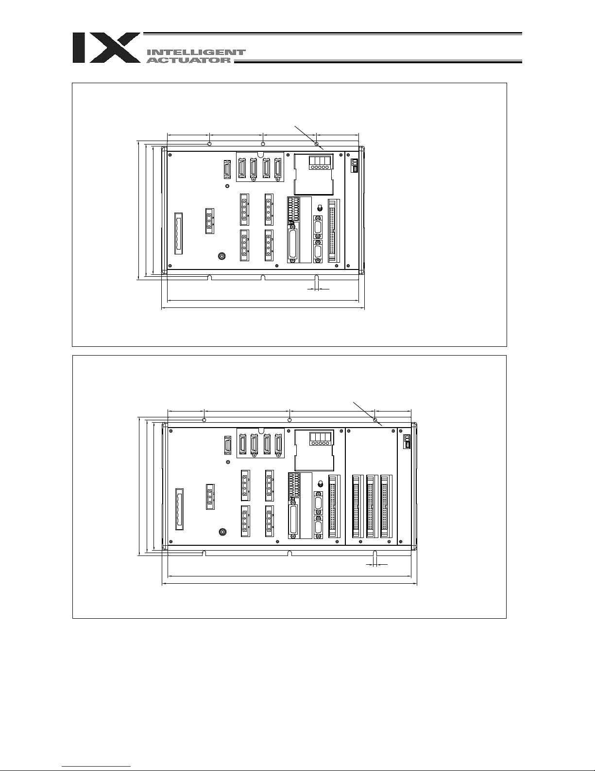
Part 1 Installation
Fig. 4-5 PX/QX Type (Three-phase Standard Specification, Single-phase Global Specification,
Single-phase Standard Specification)
4-axis specification, SCARA arm length 250 to 600 mm, without expansion I/O board
3-5
75 59.5
5
195
186
59.5 75
180
269
285
Example of applicable model: X-SEL-PX-NNN2515-N1-EEE-2-3
Fig. 4-6 PX/QX Type (Three-phase Standard Specification, Single-phase Global Specification,
Single-phase Standard Specification)
4-axis specification, SCARA arm length 250 to 600 mm, with expansion I/O board
3-5
51
5
195
186
180
51 120 120
342
358
Example of applicable model: X-SEL-PX-NNN2515-N1-N1N1N1-2-3
51
51
Page 76
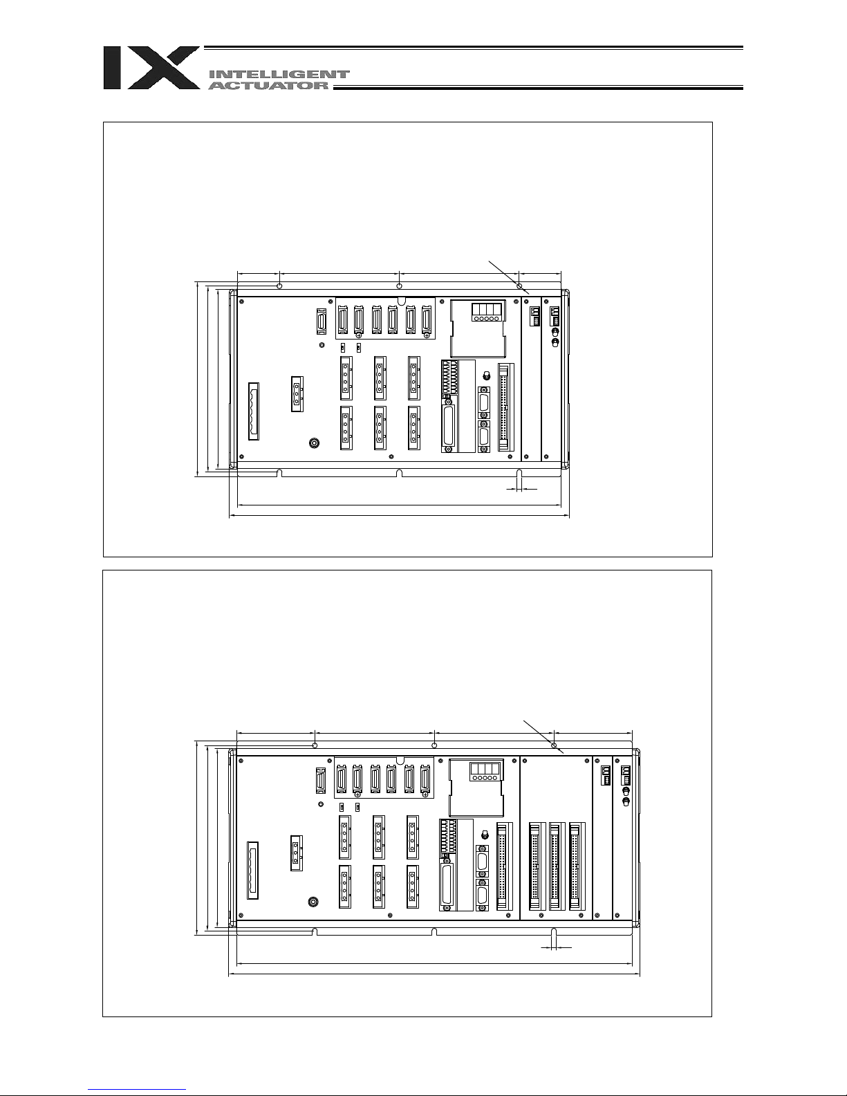
Part 1 Installation
Fig. 4-7 PX/QX Type (Three-phase Standard Specification, Single-phase Global Specification,
Single-phase Standard Specification)
5/6-axis specification, SCARA arm length 250 to 600 mm, without expansion I/O board
5/6-axis specification, SCARA arm length 120/150/180 mm, without expansion I/O board, with
absolute linear movement axis or linear movement axis with brake
SCARA arm length 700/800 mm, without expansion I/O board
High-speed type, without expansion I/O board
Availability and position of the motor connector/encoder-axis sensor connector varies depending
on the SCARA model.
3-5
42
195
186
42 120 120
180
5
324
340
Example of applicable model
: X-SEL-PX-NNN5020-400AB-200AB-N1-EEE-2-3
Fig. 4-8 PX/QX Type (Three-phase Standard Specification, Single-phase Global Specification,
Single-phase Standard Specification)
5/6-axis specification, SCARA arm length 250 to 600 mm, with expansion I/O board
5/6-axis specification, SCARA arm length 120/150/180 mm, with expansion I/O board, with
absolute linear movement axis or linear movement axis with brake
SCARA arm length 700/800 mm, with expansion I/O board
High-speed type, with expansion I/O board
Availability and position of the motor connector/encoder-axis sensor connector varies depending
on the SCARA model.
3-5
78.5
195
186
78.5 120 120
180
Example of applicable model: X-SEL-PX-NNN5020-400AB-200AB-N1-N1N1N1-2-3
52
52
397
413
5
Page 77

4.3 QX Type (Three-phase Global Specification) Controller
Fig. 4-9 QX Type (Three-phase Global Specification)
4-axis specification, SCARA arm length 120/150/180 mm, without expansion I/O board
Part 1 Installation
(80)
195
186
180
28
75
206
222
3-5
2875
5
Example of applicable model: X-SEL-QX-NNN1205-N1-EEE-2-3
Fig. 4-10 QX Type (Three-phase Global Specification)
4-axis specification, SCARA arm length 120/150/180 mm, with expansion I/O board
64.5 75
3-5
64.575
3
125.3
195
186
180
279
295
5
Example of applicable model: X-SEL-QX-NNN1205-N1-N1N1N1-2-3
53
53
Page 78

Fig. 4-11 QX Type (Three-phase Global Specification)
5/6-axis specification, SCARA arm length 120/150/180 mm, without expansion I/O
board, with incremental linear movement axis without brake
3-5
45.575
5
195
45.5 75
186
180
241
257
Example of applicable model: X-SEL-QX-NNN1205-200I-200I-N1-EEE-2-3
Part 1 Installation
Fig. 4-12 QX Type (Three-phase Global Specification)
5/6-axis specification, SCARA arm length 120/150/180 mm, with expansion I/O
board, with incremental linear movement axis without brake
195
186
37 120
180
Example of applicable model: X-SEL-QX-NNN1205-200I-200I-N1-N1N1N1-2-3
314
330
120
3-5
37
5
54
54
Page 79

Fig. 4-13 QX Type (Three-phase Global Specification)
4-axis specification, SCARA arm length 250 to 600 mm, without expansion I/O board
Part 1 Installation
3-5
3875
5
195
186
180
38
75
226
242
Example of applicable model: X-SEL-QX-NNN2521-N1-EEE-2-3
Fig. 4-14 QX Type (Three-phase Global Specification)
4-axis specification, SCARA arm length 250 to 600 mm, with expansion I/O board
29.5 120
3-5
29.5120
195
186
180
Example of applicable model: X-SEL-QX-NNN2515-200I-200I-N1-N1N1N1-2-3
299
315
5
55
55
Page 80

Fig. 4-15 QX Type (Three-phase Global Specification)
5/6-axis specification, SCARA arm length 250 to 600 mm, without expansion I/O board
5/6-axis specification, SCARA arm length 120/150/180 mm, without expansion I/O board, with
absolute linear movement axis or linear movement axis with brake
SCARA arm length 700/800 mm, without expansion I/O board
High-speed type, without expansion I/O board
Availability and position of the motor connector/encoder-axis sensor connector varies depending
on the SCARA model.
Part 1 Installation
20.5 120
195
186
180
281
297
Example of applicable model: X-SEL-QX-NNN5020-400AB-200AB-N1-EEE-2-3
Fig. 4-16 QX Type (Three-phase Global Specification)
5/6-axis specification, SCARA arm length 250 to 600 mm, with expansion I/O board
5/6-axis specification, SCARA arm length 120/150/180 mm, with expansion I/O board, with
absolute linear movement axis or linear movement axis with brake
SCARA arm length 700/800 mm, with expansion I/O board
High-speed type, with expansion I/O board
Availability and position of the motor connector/encoder-axis sensor connector varies depending
on the SCARA model.
3-5
20.5120
5
57 120
195
186
180
Example of applicable model: X-SEL-QX- NNN5020-400AB-200AB-N1-N1N1N1-2-3
56
56
354
370
3-5
57120
5
Page 81

Part 1 Installation
Chapter 6 Safety Circuit
The circuit configuration for embodying safety actions such as emergency stop is different between the
standard specification and global specification of the X-SEL controller.
The standard controller has a built-in drive source cutoff circuit conforming to safety category B.
The global controller has no built-in drive source cutoff circuit so that the user can configure an external
safety circuit appropriate for their equipment configuration.
1. Items to Notes
The following explains the items to note regarding the safety circuit, which apply to both the standard
specification and global specification.
1. Overview of emergency stop action
The emergency stop control line (drive source cutoff control line) consists entirely of wires. When an
emergency stop operation is performed, the controller will execute a stop action of category 1.
Specifically, it will stop the actuator at the deceleration for emergency stop as specified by a
parameter, and turn off the servo. At this time, the drive source will also be cut off inside the standard
controller. With the global controller, the drive source must be cut off externally to the controller.
As for recovery from an emergency stop state (including recovery of the drive source), an automatic
reset using the emergency stop switch or a method requiring both an emergency stop switch action
and an external input signal can be selected by a parameter (I/O parameter No. 44).
During an emergency stop, the status can be output to an external device (set by I/O parameter No.
48).
2. Overview of enabling action
Enabling operation (via the safety gate or the deadman switch on the teaching pendant) implements
an action similar to the emergency stop action, except that an emergency stop status is not output.
3. Controller operation modes and safety switches on the teaching pendant
The deadman switch on the teaching pendant is enabled only when the controller is in the MANU
mode. The emergency stop switch on the teaching pendant is always enabled as long as the
teaching pendant is connected to the controller.
4. Connecting a teaching pendant while the controller is operating in the AUTO mode
Connecting a teaching pendant to the controller or removing the connected teaching pendant while
the controller is operating in the AUTO mode may trigger an emergency stop. Do not connect/remove
a teaching pendant while the controller is operating in the AUTO mode.
5. Applying voltage to the system I/O
The safety circuit of the X-SEL controller is designed to operate with 24 VDC. Therefore, never apply
100 or 200 VAC to the system I/O. Doing so may damage the internal circuitry of the controller.
The following pages explain the safety circuit of each controller specification in details.
57
57
Page 82

Part 1 Installation
2. Safety Circuit for PX Type (Standard Specification) Controller
The PX type controller has a built-in drive source cutoff circuit just like IAI’s other controllers.
The drive source cutoff circuit consists of a relay and conforms to safety category B. If your equipment
must meet a higher safety category, use the QX type (global specification) controller explained later.
Connect the control power supply and motor power supply to the same power source and also turn on/off
the control power supply and motor power supply at the same time.
The teaching pendant port can be connected to either an IAI’s standard teaching pendant or ANSI
teaching pendant. Note, however, that redundant safety circuits cannot be configured even if an ANSI
teaching pendant is used.
Set the teaching pendant type switch located above the teaching pendant connector to the position
appropriate for the teaching pendant used. Set the switch to the left for an ANSI teaching pendant, or to
the right for IAI’s standard teaching pendant.
Note: If the teaching pendant type switch is not set properly, the safety gate switch will not function.
The emergency stop line and enabling line are driven by the controller’s internal power supply. It should
be noted that the safety circuit cannot be driven by an external power source.
Do not use the internal power supply provided for the system I/O connector, for any other purpose. It may
damage the equipment or cause it to malfunction.
The tables below list the signals and wiring methods of the safety circuit interface connector.
System I/O Connector for PX Type
Item Overview Details
COMBICON (2-row, 9-pin) MCD1.5/9-G1-3.5P26THR (by Phoenix Contact)
Connector
Cable end connector FMC1.5/9-ST-3.5
2
Applicable cable size 0.2 to 1.3 mm
(AWG24-16)
Terminal Assignments
Pin
Signal
No.
name
9 DET IN Not connected Not used
8 IN To external EMG Emergency-stop detection input
EMGin
7
6 line+
Left
EMG1
5
4 line+ Not connected
EMG2
3
2 Out+ Not connected
SDN
1
18 DET +24 V Not connected Not used
17 IN To external ENB Enable detection input
ENBin
16
15 line+
Right
ENB1
14
13 line+ Not connected
ENB2
12
11 Out+
RDY
10
Overview Details
+24 V
Shorted
Wired before shipment
24 V power output for emergency-stop
detection input
Emergency stop switch 1
line- To external EMG
Wire circuit 1 connected to EMG of the TP
Not used
line- Not connected
External relay drive cutoff contact outputs
Out- Not connected
+24 V 24 V power output for enable detection input
line- To external ENB
Shorted
Wired before shipment
Enable switch 1 (safety gate, etc.)
Wire circuit 1 connected to ENB of the TP
Not used
line- Not connected
Out-
May be used if
necessary
Ready signal contact outputs (dry contacts)
(for inductive load of up to 400 mA)
58
58
Page 83

Part 1 Installation
With the PX type, use only the signals shown in the shaded fields of the table for connection with the
safety switches.
Ensure that the specified pins are wired correctly, as incorrect wiring will compromise the safety
mechanisms of the controller.
The RDYOUT contacts will close only when the controller has started properly. By connecting these
contacts in series with similar contacts of other equipment, the soundness of the entire system can be
checked easily.
PX type X-SEL controller External emergency stop circuit
Emergency stop switch
Enable switch
59
59
Page 84

Part 1 Installation
3. Safety Circuit for QX Type (Global Specification) Controller
The global controller has no internal drive source cutoff circuit so that the user can configure a desired
drive source cutoff circuit externally to the controller to conform to the required safety category.
The safety circuit consists of two circuits: the emergency stop (EMG) circuit and enable (ENB) circuit.
Each circuit adopts a redundant design, so a safety circuit conforming to a higher safety category of up to
level 4 can be configured using an external drive source cutoff circuit.
Since this controller has no built-in drive source cutoff circuit, be sure to install a drive source cutoff circuit
in the motor power circuit. It is recommended that the control power supply be wired from the same power
source as the motor power supply at a point before the drive-source cutoff part is connected.
Please note that IAI is not liable for any losses arising from a malfunction of the safety circuit configured
by the user.
The ANSI safety standard can be met only when an ANSI teaching pendant is connected to the teaching
port.
The redundant emergency stop lines and enabling lines are designed with the assumption that they will be
driven by a power source external to the controller. Note, however, that the inputs to the contacts that
provide for emergency stop action and enabling action operate on the internal power supply.
Do not use the internal power supply provided for the system I/O connector for any other purpose. It may
damage the equipment or cause it to malfunction.
The tables below list the signals and wiring methods of the safety circuit interface connector. The
connector pin assignments and internal circuit components are the same as those of the standard
specification.
System I/O Connector for QX type
Item Overview Details
Connector
COMBICON (2-row, 9-pin) MCD1.5/9-G1-3.5P26THR (by Phoenix Contact)
Cable end connector FMC1.5/9-ST-3.5
Applicable cable size 0.2 ~ 1.3 mm
2
(AWG24-16)
60
60
Page 85

Terminal Assignments
Left
Right
Pin
No.
18 DET +24 V
17 IN Enable detection input
16
15 line+
14
13 line+
12
11 Out+
10
Signal
name
9 DET IN
8 IN Emergency stop detection input
EMGin
7
6 line+
EMG1
5
4 line+
EMG2
3
2 Out+
1
SDN
ENBin
ENB1
ENB2
RDY
+24 V
line-
line-
Out-
+24 V
line-
line-
Out-
Part 1 Installation
Overview Details
To fused-contact
detection circuit
To EMG status
of safety circuit
To EMG switch
circuit 1
To EMG switch
circuit 2
To interlock of
safety circuit
To fused-contact
detection circuit
To EMB status
of safety circuit
To enable circuit
1
To enable circuit
2
May be used if
necessary
External contact error input (paired with No. 18)
Connected to the fused contact detection contacts of
the safety circuit.
24 V power output for emergency stop detection input
Emergency stop switch 1
Wire circuit 1 connected to EMG of the TP
Emergency-stop switch 2
Wire circuit 2 connected to EMG of the TP
External relay drive cutoff contact output
Signal for requesting the controller to cutoff the drive
source
24 V power output for external contact error input
Connected to the fused contact detection contacts of
the safety circuit.
24 V power output for enable detection input
Enable switch 1 (safety gate, etc.)
Wire circuit 1 connected to ENB of the TP
Enable switch 2
Wire circuit 2 connected to ENB of the TP
Ready signal contact outputs (for inductive load of up to
400 mA)
In the table, the signals shown in fields (EMGin, EMG1, SDN, ENBin, ENB1) must always be
connected regardless of the required safety category. If these signals are not connected, the safety
functions will be compromised.
In the table, the signals shown in fields (EMG2, ENB2) must be connected to meet safety category 3
or above. They are designed to provide redundant safety circuits.
In the table, the signal shown in fields (DET) provides an input for detecting malfunction of the safety
circuit (mainly fused relay contacts). This signal is disabled when the controller is shipped. To enable the
DET input, set bits 8 to 11 of I/O parameter No. 24 to “1” (= change I/O parameter No. 24 from the default
setting of 10000 to 10100).
Be sure to use this signal if you want the X-SEL controller to detect fused contacts. If the safety circuit is
configured as a closed system to manage fused contacts and other problems independently, safety
category 4 can be met without connecting this signal to the controller.
DET
DET (IN) and DET (+24V) are dry contact input terminals consisting of a photocoupler. By inputting
fused contact detection signals from the drive source cutoff safety circuit, the controller will be able to
detect problems in the external safety circuit. To use the DET terminal, change I/O parameter No. 24
from the default setting of 10000 to 10100 (by setting bits 8 to 11 of I/O parameter No. 24 to “1”).
SDN
SDN (OUT+) and SDN (OUT-) are output contacts that remain open while the controller is prohibiting
the motor power supply from the external power source. This condition will occur immediately after the
controller power is turned on, when an error occurs in the equipment, or when a drive source cutoff
cancellation command is not received by the EMG or ENB line. Configure the circuit in such a way that
the drive source will never be turned on when these contacts are open.
When turning on the power, turn on the controller power first, confirm that the SDN contacts are closed,
and then turn on the drive power. (If the control power and drive power are turned on simultaneously,
“E6D: Drive-source cutoff relay error” will generate.
61
61
Page 86

Part 1 Installation
EMG1/EMG2, ENB1/ENB2
EMG1 (line+)/(line-) and EMG2 (line+)/(line-) are redundant emergency stop control lines.
ENB1 (line+)/(line-) and ENB2 (line+)/(line-) are redundant enabling control lines.
Use these lines to cut off the external drive source. Since they are completely dry signal lines,
configure a relay circuit using an external power source.
EMGin, ENBin
EMGin (IN) and EMGin (+24V) are contact inputs that notify the controller of the drive source cutoff
input received by the drive source cutoff circuit via an EMG signal. ENBin (IN) and ENBin (+24V) are
contact inputs that notify the controller via an ENB signal. These contact signals are used to decelerate
the actuator to a stop or turn off the servo. Normally, a safety relay output is connected to each of
these inputs.
RDY
RDY (OUT+) and RDY (OUT-) are output contacts that will close only when the controller has started
properly. By connecting these contacts in series with similar contacts of other equipment, the
soundness of the entire system can be checked easily.
62
62
Page 87

Power supply part
Part 1 Installation
QX Type X-SEL Controller
Digital control part
DC bus
To power stage
Teaching pendant
Mushroom emergencystop switch
EMG SW
contact 1
EMG SW
contact 2
Rectifier
Not installed
AC cutoff relay
External
emergency-stop
reset contact output
Power-on reset
MPSDW N bit
Power error
Double-position enablingcontrol switch
DEADMAN
SW
contact 1
DEADMAN
SW
contact 2
Emergency-stop status
Enable status
63
63
Page 88

External Emergency Stop Circuit
Part 1 Installation
200-VAC,
three-
phase
External emergency-stop switch
External
EMG switch
contact 1
External
EMG switch
contact 2
Safety gate switch
External
SGATE
contact 1
Contactor (NEO SC)
Reset switch
Relay
Contactor (NEO SC)
Safety relay unit
(G9SA-301 by Omron)
External
SGATE
contact 2
64
64
Page 89

Part 1 Installation
4. Timing Chart of Safety Circuit for QX-type SEL Controller
A timing chart of the safety circuit for QX-type SEL controller is shown below.
The points in time shown in this timing chart are: “[1] Power on,” “[2] Emergency stop,” “[3] Power on
without cancelling emergency stop,” “[4] Enable operation,” “[5] System shutdown level error,” [6] “Cold
start level error,” “[7] Operation cancellation level error,” “[8] Power on (in combination with cutoff reset
input),” and “[9] Emergency stop (in combination with cutoff reset input).”
[1] Power on
200-VAC control power
Normal CPU start
I/O output signal: Port No. 301
Ready output
Rdy (system I/O)
SDN (system I/O)
EMG1, EMG2 (system I/O)
ENB1, ENB2 (system I/O)
Occurrence of secret level error
Occurrence of message level error
Occurrence of operation cancellation level error
Occurrence of cold start level error
Occurrence of system shutdown level error
I/O parameter No. 24, bits 0 to 3 = 0: The RDYOUT output (system I/O) is SYSRDY (PIO trigger
program operation enabled) and the hardware is normal
(emergency stop is not actuated and no hardware errors are
detected).
I/O parameter No. 44 = 0: The drive-source cutoff reset input is not yet used.
I/O parameter No. 47 = 3: Output function 301 = READY output (PIO program operation
enabled and no errors of cold start level or higher have
occurred).
65
65
Page 90

[2] Emergency stop
200-VAC control power
Normal CPU start
I/O output signal: Port No. 301
Ready output
Rdy (system I/O)
SDN (system I/O)
EMG1, EMG2 (system I/O)
ENB1, ENB2 (system I/O)
Part 1 Installation
Emergency stop SW = ON Emergency stop SW = OFF
Occurrence of secret level error
Occurrence of message level error
Occurrence of operation cancellation level error
Occurrence of cold start level error
Occurrence of system shutdown level error
I/O parameter No. 24, bits 0 to 3 = 0: The RDYOUT output (system I/O) is SYSRDY (PIO trigger
program operation enabled) and the hardware is normal
(emergency stop is not actuated and no hardware errors are
detected).
I/O parameter No. 44 = 0: The drive-source cutoff reset input is not yet used.
I/O parameter No. 47 = 3: Output function 301 = READY output (PIO program operation
enabled and no errors of cold start level or higher have
occurred).
66
66
Page 91
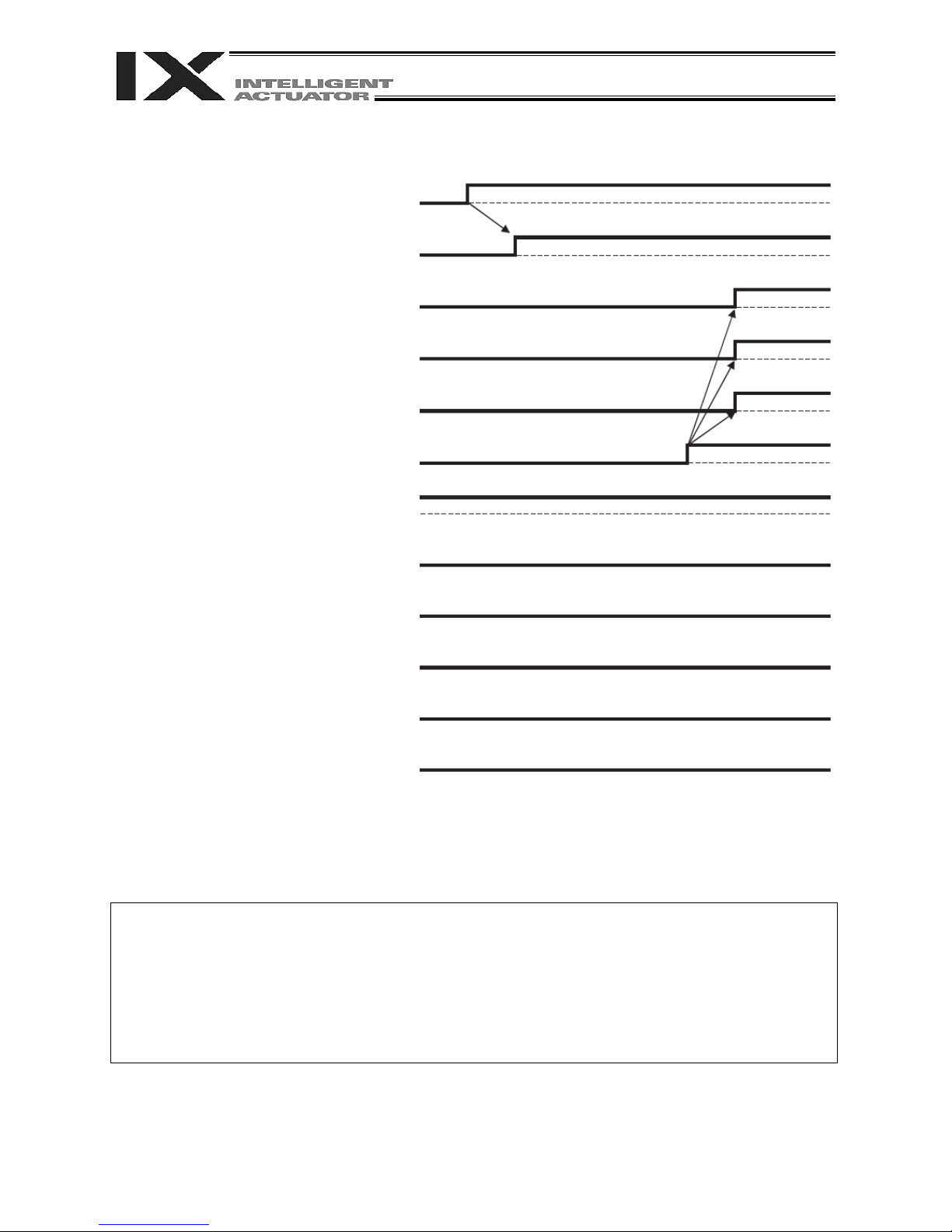
[3] Power on without cancelling emergency stop
200-VAC control power
Normal CPU start
I/O output signal: Port No. 301
Ready output
Rdy (system I/O)
SDN (system I/O)
Part 1 Installation
EMG1, EMG2 (system I/O)
Rdy and SDN = ON due to
cancellation of emergency stop
ENB1, ENB2 (system I/O)
Occurrence of secret level error
Occurrence of message level error
Occurrence of operation cancellation level error
Occurrence of cold start level error
Occurrence of system shutdown level error
Assume that the same timings will apply when the power is turned on without performing an enable
operation.
I/O parameter No. 24, bits 0 to 3 = 0: The RDYOUT output (system I/O) is SYSRDY (PIO trigger
I/O parameter No. 44 = 0: The drive-source cutoff reset input is not yet used.
I/O parameter No. 47 = 3: Output function 301 = READY output (PIO program operation
program operation enabled) and the hardware is normal
(emergency stop is not actuated and no hardware errors are
detected).
enabled and no errors of cold start level or higher have
occurred).
67
67
Page 92
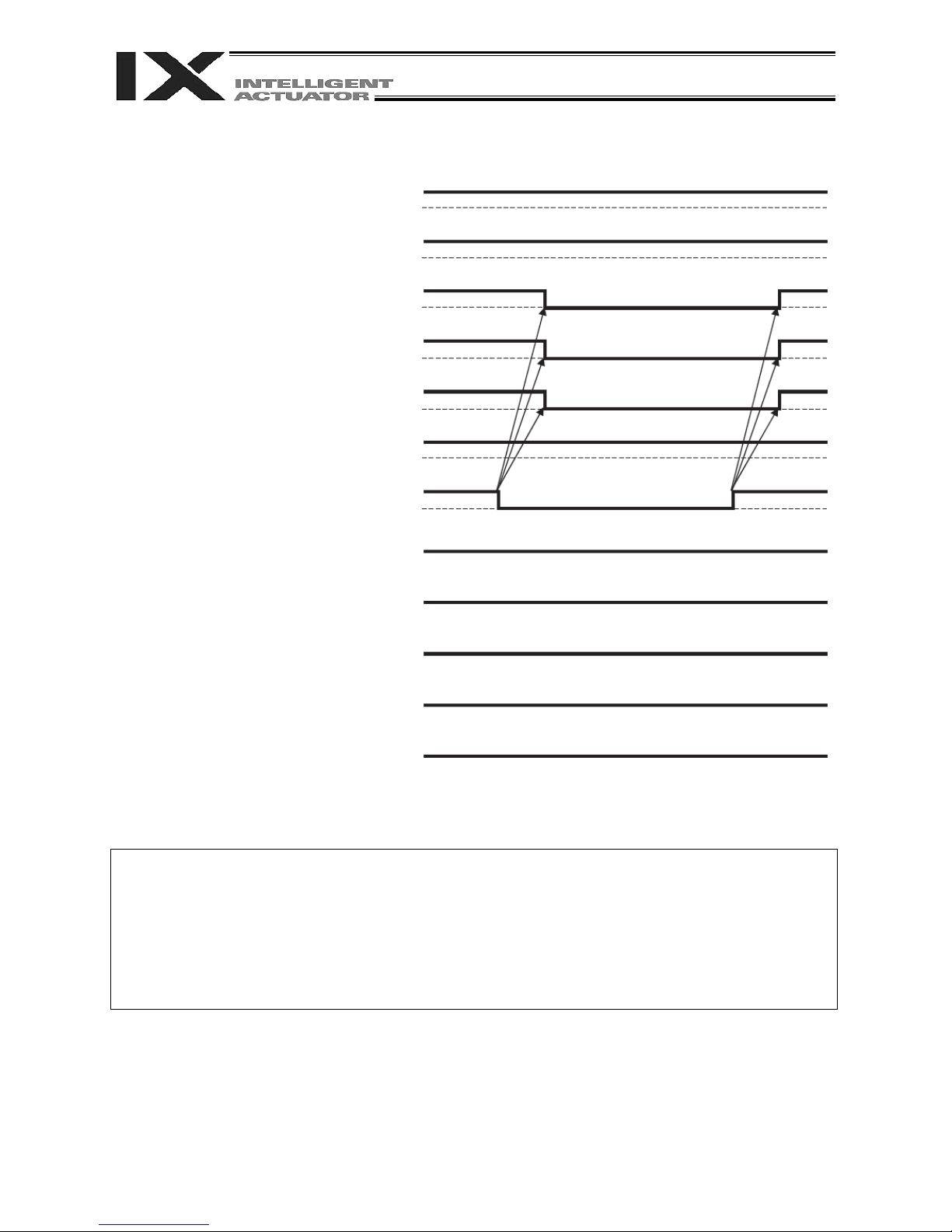
[4] Enable operation
200-VAC control power
Normal CPU start
I/O output signal: Port No. 301
Ready output
Rdy (system I/O)
SDN (system I/O)
EMG1, EMG2 (system I/O)
ENB1, ENB2 (system I/O)
Part 1 Installation
Enable SW = ON Enable SW = OFF
Occurrence of secret level error
Occurrence of message level error
Occurrence of operation cancellation level error
Occurrence of cold start level error
Occurrence of system shutdown level error
I/O parameter No. 24, bits 0 to 3 = 0: The RDYOUT output (system I/O) is SYSRDY (PIO trigger
program operation enabled) and the hardware is normal
(emergency stop is not actuated and no hardware errors are
detected).
I/O parameter No. 44 = 0: The drive-source cutoff reset input is not yet used.
I/O parameter No. 47 = 3: Output function 301 = READY output (PIO program operation
enabled and no errors of cold start level or higher have
occurred).
68
68
Page 93

[5] System shutdown level error
200-VAC control power
Normal CPU start
I/O output signal: Port No. 301
Ready output
Rdy (system I/O)
SDN (system I/O)
EMG1, EMG2 (system I/O)
ENB1, ENB2 (system I/O)
Part 1 Installation
Occurrence of secret level error
Occurrence of message level error
Occurrence of operation cancellation level error
Occurrence of cold start level error
Occurrence of system shutdown level error
I/O parameter No. 24, bits 0 to 3 = 0: The RDYOUT output (system I/O) is SYSRDY (PIO trigger
program operation enabled) and the hardware is normal
(emergency stop is not actuated and no hardware errors are
detected).
I/O parameter No. 44 = 0: The drive-source cutoff reset input is not yet used.
I/O parameter No. 47 = 3: Output function 301 = READY output (PIO program operation
enabled and no errors of cold start level or higher have
occurred).
69
69
Page 94

[6] Cold start level error
200-VAC control power
Normal CPU start
I/O output signal: Port No. 301
Ready output
Part 1 Installation
Rdy (system I/O)
SDN (system I/O)
EMG1, EMG2 (system I/O)
ENB1, ENB2 (system I/O)
Occurrence of secret level error
Occurrence of message level error
Occurrence of operation cancellation level error
Occurrence of cold start level error
Occurrence of system shutdown level error
The timings of SDN and Rdy may be
slightly early or late depending on
the nature of the error.
I/O parameter No. 24, bits 0 to 3 = 0: The RDYOUT output (system I/O) is SYSRDY (PIO trigger
I/O parameter No. 44 = 0: The drive-source cutoff reset input is not yet used.
I/O parameter No. 47 = 3: Output function 301 = READY output (PIO program operation
70
70
program operation enabled) and the hardware is normal
(emergency stop is not actuated and no hardware errors are
detected).
enabled and no errors of cold start level or higher have
occurred).
Page 95

[7] Operation cancellation level error
200-VAC control power
Normal CPU start
I/O output signal: Port No. 301
Ready output
Rdy (system I/O)
SDN (system I/O)
EMG1, EMG2 (system I/O)
ENB1, ENB2 (system I/O)
Part 1 Installation
Occurrence of secret level error
Occurrence of message level error
Occurrence of operation cancellation level error
Rdy and SDN are not affected by errors of
operation cancellation level or lower.
Occurrence of cold start level error
Occurrence of system shutdown level error
I/O parameter No. 24, bits 0 to 3 = 0: The RDYOUT output (system I/O) is SYSRDY (PIO trigger
program operation enabled) and the hardware is normal
(emergency stop is not actuated and no hardware errors are
detected).
I/O parameter No. 44 = 0: The drive-source cutoff reset input is not yet used.
I/O parameter No. 47 = 3: Output function 301 = READY output (PIO program operation
enabled and no errors of cold start level or higher have
occurred).
71
71
Page 96
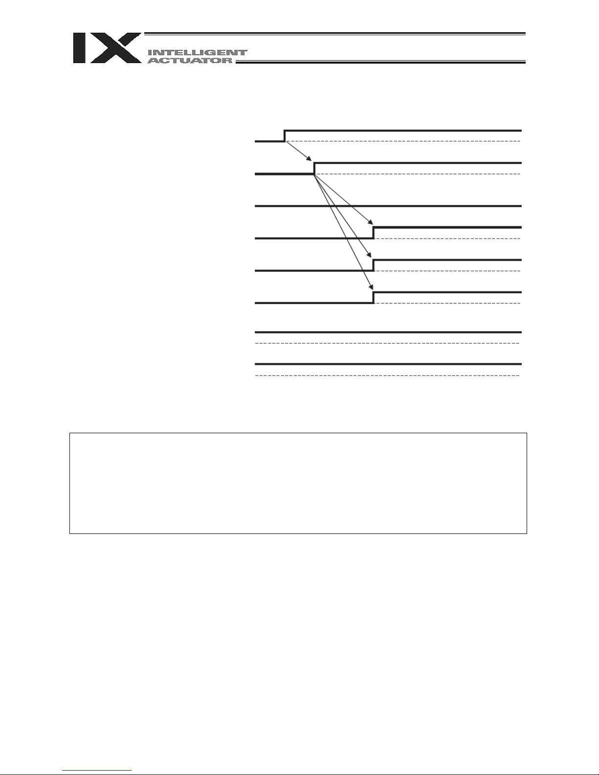
[8] Power on (in combination with drive-source cutoff reset input)
200-VAC control power
Normal CPU start
I/O input signal: Port No. 14
Drive-source cutoff reset input
I/O output signal: Port No. 301
Ready output
Rdy (system I/O)
SDN (system I/O)
Part 1 Installation
EMG1, EMG2 (system I/O)
ENB1, ENB2 (system I/O)
I/O parameter No. 24, bits 0 to 3 = 0: The RDYOUT output (system I/O) is SYSRDY (PIO trigger
program operation enabled) and the hardware is normal
(emergency stop is not actuated and no hardware errors are
detected).
I/O parameter No. 44 = 0: The drive-source cutoff reset input is not yet used.
I/O parameter No. 47 = 3: Output function 301 = READY output (PIO program operation
enabled and no errors of cold start level or higher have
occurred).
72
72
Page 97
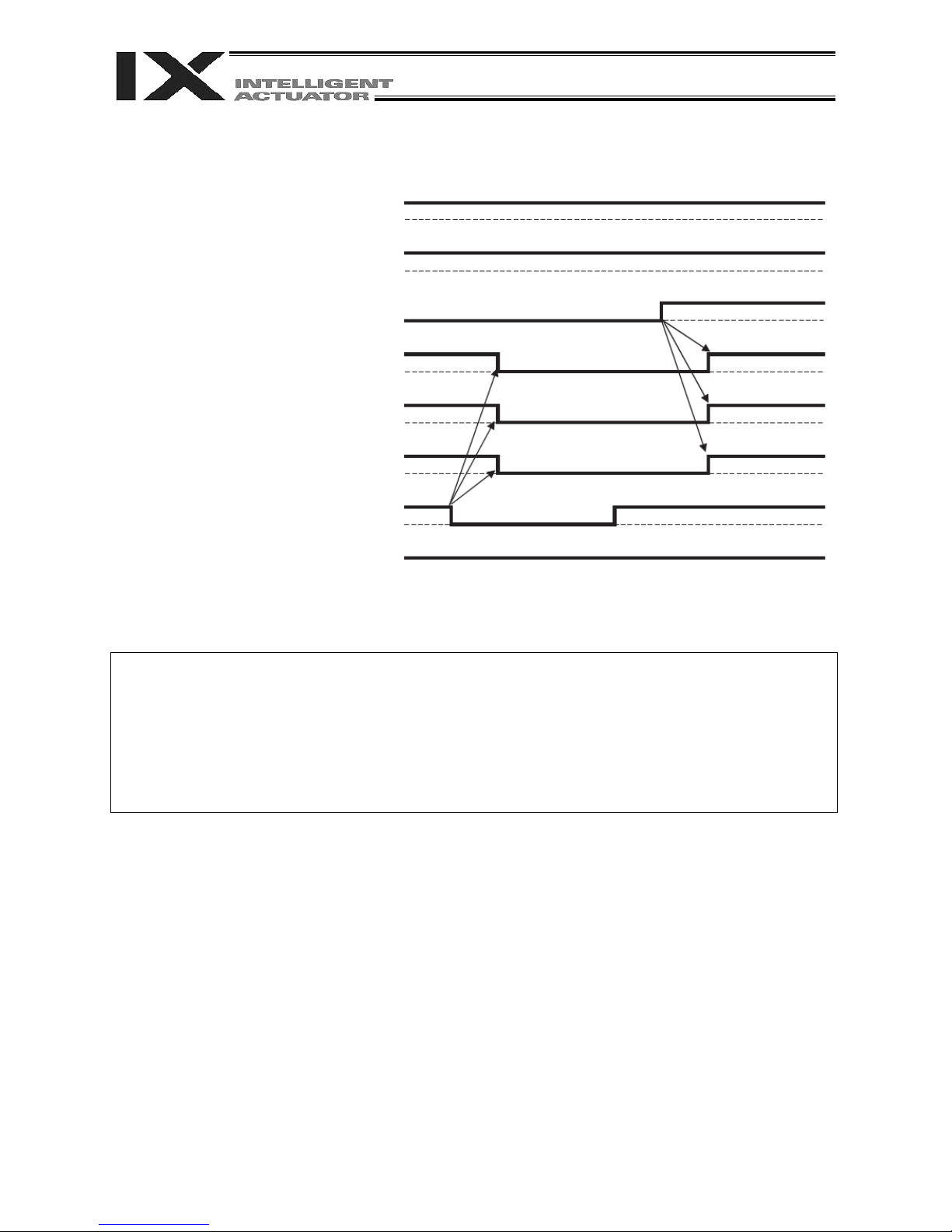
[9] Emergency stop (in combination with drive-source cutoff reset input)
200-VAC control power
Normal CPU start
I/O input signal: Port No. 14
Drive-source cutoff reset input
I/O output signal: Port No. 301
Ready output
Rdy (system I/O)
SDN (system I/O)
EMG1, EMG2 (system I/O)
Emergency stop SW = ON Emergency stop SW = OFF
ENB1, ENB2 (system I/O)
Part 1 Installation
I/O parameter No. 24, bits 0 to 3 = 0: The RDYOUT output (system I/O) is SYSRDY (PIO trigger
program operation enabled) and the hardware is normal
(emergency stop is not actuated and no hardware errors are
detected).
I/O parameter No. 44 = 0: The drive-source cutoff reset input is not yet used.
I/O parameter No. 47 = 3: Output function 301 = READY output (PIO program operation
enabled and no errors of cold start level or higher have
occurred).
73
73
Page 98

Chapter 7 System Setup
A
1. Connection Method of Controller and Actuator
1.1 Connection Diagram for PX Type (Standard Specification)
Emergency-
stop switch
Three-phase specification
CP: Single-phase 200 to 230 VAC
power supply
MP: Three-phase 200 to 230 VAC
power supply
Single-phase specification
CP: Single-phase 200 to 230 VAC
power supply
MP: Three-phase 200 to 230 VAC
power supply
Auxiliary power
device circuit
Enable
switch
bsolute-encoder backup
battery enable/disable
switch for linear movement
axis
Teaching-pendant type
switch
Part 1 Installation
24-V power
source
Regenerative unit
(optional)
Axis 6
Axis 5
Brake/ absolute
PC connection
cable
CB-STE1MW050
unit
24-V power
source
Host system
Teaching
pendant
(optional)
PC software IA-101-X-MW
PC
(PLC)
74
74
Page 99

1.2 Connection Diagram for QX Type (Global Specification)
A
Three-phase specification
CP: Single-phase 200 to 230 VAC
power supply
MP: Three-phase 200 to 230 VAC
power supply
Single-phase specification
CP: Single-phase 200 to 230 VAC
power supply
MP: Three-phase 200 to 230 VAC
power supply
Auxiliary power
device circuit
Safety circuit
bsolute-encoder backup
battery enable/disable switch
for linear movement axis
Part 1 Installation
24-V power
source
Regenerative unit
(optional)
Axis 6
Axis 5
Brake/
absolute unit
PC connection cable
CB-ST-A1MW050
24-V power
source
Host system
(PLC)
Teaching pendant
(optional)
Dummy plug (for
AUTO operation)
PC software IA-101-XA-MW
PC
Warning : The internal components of the controller may burn if the following cable is used to connect
XSEL-QX to a computer.
PC software IA-101-X-MW
Accessory cable CB-ST-E1MW050 (black)
Even though the PC software can be used, make sure to use the cable CB-ST-A1MW050
(gray).
75
75
Page 100

Part 1 Installation
r
r
The positions of motor connectors and encoder connectors vary depending on the SCARA type.
The figure below shows where the motor connectors and encoder connectors are located for each SCARA
type, as viewed from the front side of the controller.
Arm length 700/800 High-speed type (NSN**----)
Encoder connector
for additional linear
movement axis
Motor connector
for additional linea
movement axis
Other than the above
Encoder connector
for additional linear
movement axis
Encoder connector
for SCARA axis
Motor
connector for
SCARA axis
Encoder connector
for SCARA axis
Encoder connector
for SCARA axis
Motor
connector for
SCARA axis
Motor connector
for additional linea
movement axis
76
76
Motor
connector for
SCARA axis
 Loading...