

Page 1

Controller Applicable for MECHATROLINK-䜕
Instruction Manual Frist Edition
SCON-CA
Page 2

Page 3

Please Read Before Use
Thank you for purchasing our product.
This Instruction Manual explains the handling methods, structure and maintenance of this product,
among others, providing the information you need to know to use the product safely.
Before using the product, be sure to read this manual and fully understand the contents explained
herein to ensure safe use of the product.
The DVD that comes with the product contains Instruction manuals for IAI products.
When using the product, refer to the necessary portions of the applicable instruction manual by
printing them out or displaying them on a PC.
After reading the Instruction Manual, keep it in a convenient place so that whoever is handling this
product can reference it quickly when necessary.
[Important]
x This Instruction Manual is original.
x This product is not to be used for any other purpose from what is noted in this Instruction
Manual. IAI shall not be liable whatsoever for any loss or damage arising from the result of using
the product for any other purpose from what is noted in the manual.
x The information contained in this Instruction Manual is subject to change without notice for the
purpose of production improvement.
x If you have any question or finding regarding the information contained in this Instruction Manual,
contact our customer center or our sales office near you.
x Using or copying all or a part of this Instruction Manual without permission is prohibited.
x MECHATROLINK is a registered trademark for MECHATROLINK Members Association.
x The company names, names of products and trademarks of each company shown in the
sentences are registered trademarks.
Page 4

Page 5

Table of Contents
Safety Guide........................................................................................................... 1
1. Overview .......................................................................................................... 9
1.1 Interface Specifications ..................................................................................................... 10
2. SCON-CA........................................................................................................11
2.1 Operation Modes and Functions........................................................................................11
2.2 Operation Modes and Functions........................................................................................11
2.3 MECHATROLINK-䜕 Interface ......................................................................................... 12
2.3.1 Name of Each Part............................................................................................... 12
2.3.2 Status LED Indicators .......................................................................................... 12
2.4 Example of Wiring ............................................................................................................. 13
2.5 Setting ............................................................................................................................... 14
2.5.1 Node Address Setting .......................................................................................... 14
2.5.2 Data length Setting .............................................................................................. 14
2.5.3 Setting of Electronic Gear Ratio........................................................................... 14
2.5.4 Check for Direction of Pulse Count...................................................................... 14
3. Flow and Commands of Basic MECHATROLINK Communication ................. 15
3.1 State Transition.................................................................................................................. 15
3.2 Command Frame Construction and Number of Transmission Bytes................................ 16
3.3 Endian ............................................................................................................................... 16
3.4 System of Units ................................................................................................................. 16
4. Command Format........................................................................................... 17
4.1 Command / Response Frame........................................................................................... 18
4.1.1 Command Code / Command Code Response (CMD/RCMD)............................. 18
4.1.2 Watchdog Data (WDT/RWDT) ............................................................................. 19
4.1.3 Command Control / Command Status (CMD_CTRL/CMD_STAT)...................... 19
4.1.4 Command Data / Respons Data (CMD_DATA/RSP_DATA)................................ 21
4.1.5 Sub Command Code / Sub Command Code Response
(SUB_CMD/SUB_RCMD) .................................................................................. 22
4.1.6 Sub Command Control / Sub Command Status
(SUB_CTRL/SUB_STAT) ................................................................................... 23
4.1.7 Sub Command Data / Sub Response Data
(SUB_CMD_DATA/SUB_RSP_DATA) ............................................................... 24
5. Command....................................................................................................... 25
5.1 Main Command................................................................................................................. 25
5.1.1 Specifications of Common Commands................................................................ 25
5.1.1.1 Invalid (NOP Code: 00
H
) ......................................................................... 25
5.1.1.2 ID Reading (ID_RD Code: 03
H
).............................................................. 26
5.1.1.3 Device Setup Request (CONFIG Code: 04
H
) ......................................... 28
5.1.1.4 Alarm / Warning Readout (ALM_RD Code: 05
H
) .................................... 29
5.1.1.5 Alarm / Warning Clear (ALM_CLR Code: 06
H
) ....................................... 30
5.1.1.6 Synchronization Establishment Request (SYNC_SET Code: 0DH)........ 30
5.1.1.7 Connection Establishment Request (CONNECT Code: 0E
H
)................. 31
5.1.1.8 Connection Release Request (DISCONNECT Code: 0F
H
) .................... 32
Page 6

5.1.2 Specifications of Standard Servo Profile Commands .......................................... 33
5.1.2.1 Servo Status Monitor (SMON Code: 30
H
)............................................... 33
5.1.2.2 Sensor-on Request (SENS_ON Code: 23H)........................................... 39
5.1.2.3 Sensor-off Request (SENS_OFF Code: 24
H
) ......................................... 40
5.1.2.4 Servo ON Request (SV_ON Code: 31
H
)................................................. 41
5.1.2.5 Servo ON Request (SV_OFF Code: 32
H
).............................................. 42
5.1.2.6 Interpolation Feeding (INTERPOLATE Code: 34
H
) ................................ 43
5.1.2.7 Positioning (POSING Code: 35H)............................................................ 44
5.1.2.8 Constant Speed Feeding (FEED Code: 36H)......................................... 46
5.1.2.9 Servo Parameter Reading (SVPRM_RD Code: 40
H
) ............................. 48
5.1.2.10 Servo Parameter Writing (SVPRM_WR Code: 41H)............................. 49
5.2 Sub Command .................................................................................................................. 50
5.2.1 Combination of Main Command and Sub Command .......................................... 50
5.2.2 Specifications of Sub Commands ........................................................................ 51
5.2.2.1 Invalid (NOP Code: 00
H
) ......................................................................... 51
5.2.2.2 Alarm / Warning Readout (ALM_RD Code: 05
H
) .................................... 52
5.2.2.3 Servo Status Monitor (SMON Code: 30H)............................................... 53
5.3 Common Parameters and Device Parameters ................................................................. 54
5.3.1 Overview .............................................................................................................. 54
5.3.2 Common Parameter List...................................................................................... 55
5.3.3 Device Parameter List.......................................................................................... 59
6. Example for Operation Sequence................................................................... 60
6.1 Cautions in Actuator Operation ......................................................................................... 61
6.1.1 Home Retern........................................................................................................ 61
6.1.2 Soft Limit .............................................................................................................. 62
6.1.3 Positioning Complete Band, Positioning Vicinity Band and Home Position
Detection Band..................................................................................................... 63
7. Parameters for Controller (SCON).................................................................. 64
7.1 Parameter List................................................................................................................... 65
7.2 Detail of Parameters Related to MECHATROLINK-Υ Settings....................................... 68
8. Troubleshooting .............................................................................................. 69
8.1 Action to Be Taken upon Occurrence of Problem............................................................. 69
8.2 Alarm Level ....................................................................................................................... 70
8.3 Alarm List .......................................................................................................................... 71
9. Change History............................................................................................... 80
Page 7

1
Safety Guide
“Safety Guide” has been written to use the machine safely and so prevent personal injury or
property damage beforehand. Make sure to read it 1before the operation of this product.
Safety Precautions for Our Products
The common safety precautions for the use of any of our robots in each operation.
No.
Operation
Description
Description
1 Model
Selection
Ɣ This product has not been planned and designed for the application
where high level of safety is required, so the guarantee of the protection
of human life is impossible. Accordingly, do not use it in any of the
following applications.
1) Medical equipment used to maintain, control or otherwise affect human
life or physical health.
2) Mechanisms and machinery designed for the purpose of moving or
transporting people (For vehicle, railway facility or air navigation
facility)
3) Important safety parts of machinery (Safety device, etc.)
Ɣ Do not use the product outside the specifications. Failure to do so may
considerably shorten the life of the product.
Ɣ Do not use it in any of the following environments.
1) Location where there is any inflammable gas, inflammable object or
explosive
2) Place with potential exposure to radiation
3) Location with the ambient temperature or relative humidity exceeding
the specification range
4) Location where radiant heat is added from direct sunlight or other large
heat source
5) Location where condensation occurs due to abrupt temperature
changes
6) Location where there is any corrosive gas (sulfuric acid or hydrochloric
acid)
7) Location exposed to significant amount of dust, salt or iron powder
8) Location subject to direct vibration or impact
Ɣ For an actuator used in vertical orientation, select a model which is
equipped with a brake. If selecting a model with no brake, the moving
part may drop when the power is turned OFF and may cause an accident
such as an injury or damage on the work piece.
Page 8

2
No.
Operation
Description
Description
2 Transportation Ɣ When carrying a heavy object, do the work with two or more persons or
utilize equipment such as crane.
Ɣ When the work is carried out with 2 or more persons, make it clear who is
to be the leader and who to be the follower(s) and communicate well with
each other to ensure the safety of the workers.
Ɣ When in transportation, consider well about the positions to hold, weight
and weight balance and pay special attention to the carried object so it
would not get hit or dropped.
Ɣ Transport it using an appropriate transportation measure.
The actuators available for transportation with a crane have eyebolts
attached or there are tapped holes to attach bolts. Follow the instructions
in the Instruction manual for each model.
Ɣ Do not step or sit on the package.
Ɣ Do not put any heavy thing that can deform the package, on it.
Ɣ When using a crane capable of 1t or more of weight, have an operator
who has qualifications for crane operation and sling work.
Ɣ When using a crane or equivalent equipments, make sure not to hang a
load that weighs more than the equipment’s capability limit.
Ɣ Use a hook that is suitable for the load. Consider the safety factor of the
hook in such factors as shear strength.
Ɣ Do not get on the load that is hung on a crane.
Ɣ Do not leave a load hung up with a crane.
Ɣ Do not stand under the load that is hung up with a crane.
3 Storage and
Preservation
Ɣ The storage and preservation environment conforms to the installation
environment. However, especially give consideration to the prevention of
condensation.
Ɣ Store the products with a consideration not to fall them over or drop due
to an act of God such as earthquake.
4 Installation
and Start
(1) Installation of Robot Main Body and Controller, etc.
Ɣ Make sure to securely hold and fix the product (including the work part). A
fall, drop or abnormal motion of the product may cause a damage or
injury.
Also, be equipped for a fall-over or drop due to an act of God such as
earthquake.
Ɣ Do not get on or put anything on the product. Failure to do so may cause
an accidental fall, injury or damage to the product due to a drop of
anything, malfunction of the product, performance degradation, or
shortening of its life.
Ɣ When using the product in any of the places specified below, provide a
sufficient shield.
1) Location where electric noise is generated
2) Location where high electrical or magnetic field is present
3) Location with the mains or power lines passing nearby
4) Location where the product may come in contact with water, oil or
chemical droplets
Page 9

3
No.
Operation
Description
Description
(2) Cable Wiring
Ɣ Use our company’s genuine cables for connecting between the actuator
and controller, and for the teaching tool.
Ɣ Do not scratch on the cable. Do not bend it forcibly. Do not pull it. Do not
coil it around. Do not insert it. Do not put any heavy thing on it. Failure to
do so may cause a fire, electric shock or malfunction due to leakage or
continuity error.
Ɣ Perform the wiring for the product, after turning OFF the power to the
unit, so that there is no wiring error.
Ɣ When the direct current power (+24V) is connected, take the great care
of the directions of positive and negative poles. If the connection direction
is not correct, it might cause a fire, product breakdown or malfunction.
Ɣ Connect the cable connector securely so that there is no disconnection
or looseness. Failure to do so may cause a fire, electric shock or
malfunction of the product.
Ɣ Never cut and/or reconnect the cables supplied with the product for the
purpose of extending or shortening the cable length. Failure to do so may
cause the product to malfunction or cause fire.
4 Installation
and Start
(3) Grounding
Ɣ The grounding operation should be performed to prevent an electric
shock or electrostatic charge, enhance the noise-resistance ability and
control the unnecessary electromagnetic radiation.
Ɣ For the ground terminal on the AC power cable of the controller and the
grounding plate in the control panel, make sure to use a twisted pair
cable with wire thickness 0.5mm
2
(AWG20 or equivalent) or more for
grounding work. For security grounding, it is necessary to select an
appropriate wire thickness suitable for the load. Perform wiring that
satisfies the specifications (electrical equipment technical standards).
Ɣ Perform Class D Grounding (former Class 3 Grounding with ground
resistance 100: or below).
Page 10

4
No.
Operation
Description
Description
4 Installation
and Start
(4) Safety Measures
Ɣ When the work is carried out with 2 or more persons, make it clear who is
to be the leader and who to be the follower(s) and communicate well with
each other to ensure the safety of the workers.
Ɣ When the product is under operation or in the ready mode, take the
safety measures (such as the installation of safety and protection fence)
so that nobody can enter the area within the robot’s movable range.
When the robot under operation is touched, it may result in death or
serious injury.
Ɣ Make sure to install the emergency stop circuit so that the unit can be
stopped immediately in an emergency during the unit operation.
Ɣ Take the safety measure not to start up the unit only with the power
turning ON. Failure to do so may start up the machine suddenly and
cause an injury or damage to the product.
Ɣ Take the safety measure not to start up the machine only with the
emergency stop cancellation or recovery after the power failure. Failure
to do so may result in an electric shock or injury due to unexpected
power input.
Ɣ When the installation or adjustment operation is to be performed, give
clear warnings such as “Under Operation; Do not turn ON the power!”
etc. Sudden power input may cause an electric shock or injury.
Ɣ Take the measure so that the work part is not dropped in power failure or
emergency stop.
Ɣ Wear protection gloves, goggle or safety shoes, as necessary, to secure
safety.
Ɣ Do not insert a finger or object in the openings in the product. Failure to
do so may cause an injury, electric shock, damage to the product or fire.
Ɣ When releasing the brake on a vertically oriented actuator, exercise
precaution not to pinch your hand or damage the work parts with the
actuator dropped by gravity.
5 Teaching Ɣ When the work is carried out with 2 or more persons, make it clear who is
to be the leader and who to be the follower(s) and communicate well with
each other to ensure the safety of the workers.
Ɣ Perform the teaching operation from outside the safety protection fence,
if possible. In the case that the operation is to be performed unavoidably
inside the safety protection fence, prepare the “Stipulations for the
Operation” and make sure that all the workers acknowledge and
understand them well.
Ɣ When the operation is to be performed inside the safety protection fence,
the worker should have an emergency stop switch at hand with him so
that the unit can be stopped any time in an emergency.
Ɣ When the operation is to be performed inside the safety protection fence,
in addition to the workers, arrange a watchman so that the machine can
be stopped any time in an emergency. Also, keep watch on the operation
so that any third person can not operate the switches carelessly.
Ɣ Place a sign “Under Operation” at the position easy to see.
Ɣ When releasing the brake on a vertically oriented actuator, exercise
precaution not to pinch your hand or damage the work parts with the
actuator dropped by gravity.
* Safety protection Fence : In the case that there is no safety protection fence,
the movable range should be indicated.
Page 11

5
No.
Operation
Description
Description
6 Trial Operation Ɣ When the work is carried out with 2 or more persons, make it clear who is
to be the leader and who to be the follower(s) and communicate well with
each other to ensure the safety of the workers.
Ɣ After the teaching or programming operation, perform the check
operation one step by one step and then shift to the automatic operation.
Ɣ When the check operation is to be performed inside the safety protection
fence, perform the check operation using the previously specified work
procedure like the teaching operation.
Ɣ Make sure to perform the programmed operation check at the safety
speed. Failure to do so may result in an accident due to unexpected
motion caused by a program error, etc.
Ɣ Do not touch the terminal block or any of the various setting switches in
the power ON mode. Failure to do so may result in an electric shock or
malfunction.
7 Automatic
Operation
Ɣ Check before starting the automatic operation or rebooting after
operation stop that there is nobody in the safety protection fence.
Ɣ Before starting automatic operation, make sure that all peripheral
equipment is in an automatic-operation-ready state and there is no alarm
indication.
Ɣ Make sure to operate automatic operation start from outside of the safety
protection fence.
Ɣ In the case that there is any abnormal heating, smoke, offensive smell, or
abnormal noise in the product, immediately stop the machine and turn
OFF the power switch. Failure to do so may result in a fire or damage to
the product.
Ɣ When a power failure occurs, turn OFF the power switch. Failure to do so
may cause an injury or damage to the product, due to a sudden motion of
the product in the recovery operation from the power failure.
Page 12

6
No.
Operation
Description
Description
8 Maintenance
and Inspection
Ɣ When the work is carried out with 2 or more persons, make it clear who is
to be the leader and who to be the follower(s) and communicate well with
each other to ensure the safety of the workers.
Ɣ Perform the work out of the safety protection fence, if possible. In the
case that the operation is to be performed unavoidably inside the safety
protection fence, prepare the “Stipulations for the Operation” and make
sure that all the workers acknowledge and understand them well.
Ɣ When the work is to be performed inside the safety protection fence,
basically turn OFF the power switch.
Ɣ When the operation is to be performed inside the safety protection fence,
the worker should have an emergency stop switch at hand with him so
that the unit can be stopped any time in an emergency.
Ɣ When the operation is to be performed inside the safety protection fence,
in addition to the workers, arrange a watchman so that the machine can
be stopped any time in an emergency. Also, keep watch on the operation
so that any third person can not operate the switches carelessly.
Ɣ Place a sign “Under Operation” at the position easy to see.
Ɣ For the grease for the guide or ball screw, use appropriate grease
according to the Instruction Manual for each model.
Ɣ Do not perform the dielectric strength test. Failure to do so may result in
a damage to the product.
Ɣ When releasing the brake on a vertically oriented actuator, exercise
precaution not to pinch your hand or damage the work parts with the
actuator dropped by gravity.
Ɣ The slider or rod may get misaligned OFF the stop position if the servo is
turned OFF. Be careful not to get injured or damaged due to an
unnecessary operation.
Ɣ Pay attention not to lose the cover or untightened screws, and make sure
to put the product back to the original condition after maintenance and
inspection works.
Use in incomplete condition may cause damage to the product or an
injury.
* Safety protection Fence : In the case that there is no safety protection
fence, the movable range should be indicated.
9 Modification
and Dismantle
Ɣ Do not modify, disassemble, assemble or use of maintenance parts not
specified based at your own discretion.
10 Disposal Ɣ When the product becomes no longer usable or necessary, dispose of it
properly as an industrial waste.
Ɣ When removing the actuator for disposal, pay attention to drop of
components when detaching screws.
Ɣ Do not put the product in a fire when disposing of it.
The product may burst or generate toxic gases.
11 Other Ɣ Do not come close to the product or the harnesses if you are a person
who requires a support of medical devices such as a pacemaker. Doing
so may affect the performance of your medical device.
Ɣ See Overseas Specifications Compliance Manual to check whether
complies if necessary.
Ɣ For the handling of actuators and controllers, follow the dedicated
Instruction manual of each unit to ensure the safety.
Page 13
7
Alert Indication
The safety precautions are divided into “Danger”, “Warning”, “Caution” and “Notice” according to
the warning level, as follows, and described in the Instruction Manual for each model.
Level Degree of Danger and Damage Symbol
Danger
This indicates an imminently hazardous situation which, if the product
is not handled correctly, will result in death or serious injury.
Danger
Warning
This indicates a potentially hazardous situation which, if the product is
not handled correctly, could result in death or serious injury.
Warning
Caution
This indicates a potentially hazardous situation which, if the product is
not handled correctly, may result in minor injury or property damage.
Caution
Notice
This indicates lower possibility for the injury, but should be kept to use
this product properly.
Notice
Page 14

8
Page 15
1. Overview
9
1. Overview
MECHATROLINK is an open field network for communication of both control and data signals of
the machine/line control level.
A wire-saving system can be built by connecting SCON-CA controllers (hereinafter collectively and
individually referred to as “Controller”) to a MECHATROLINK.
Supported servo profile is standard servo profile. It is not applied for the standard I/O profile.
* For details on MECHATROLINK and the command specifications of the servo profile, refer to the
operation manual for the programmable controller (hereinafter referred to as “PLC”) in which the
master unit is installed and documents offered by MECHATROLINK Members Association.
This instruction manual should be used in conjunction with the operation manual for each
controller.
You should also assume that any usage not specifically permitted in this instruction manual is
prohibited.
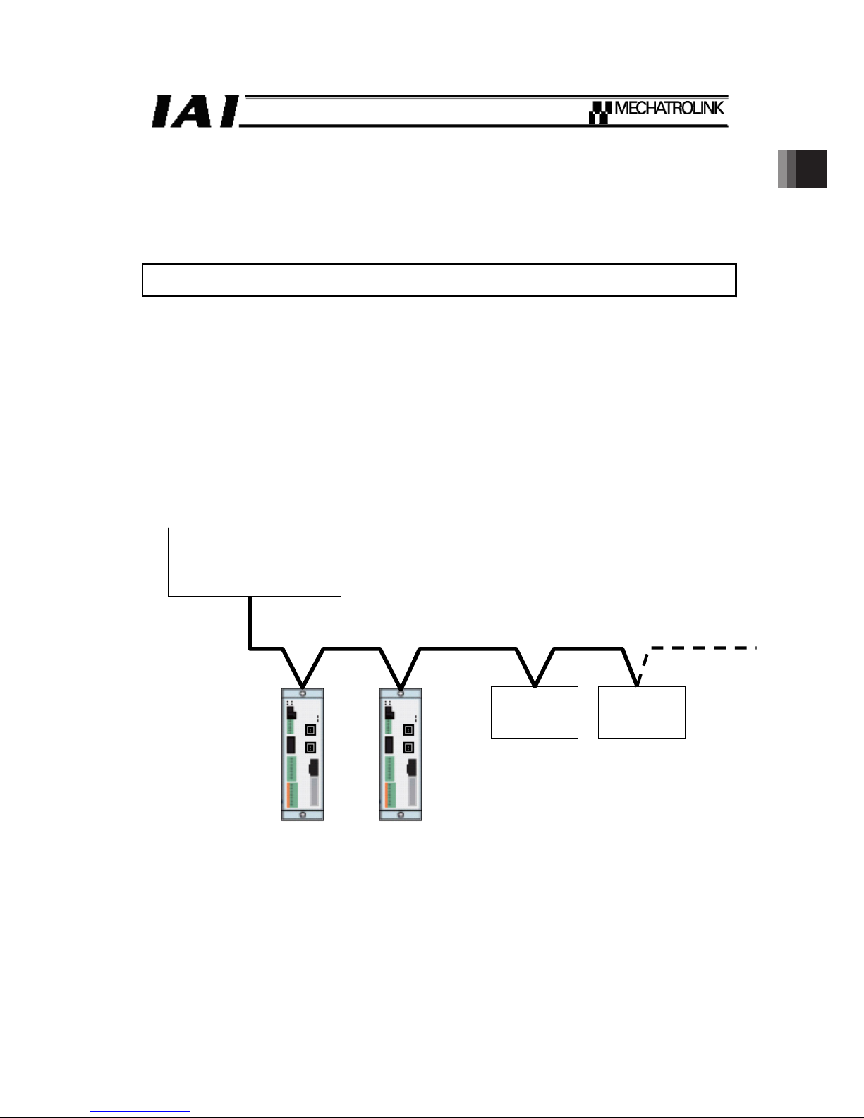
Example of a system configuration
PLC
(MECHATROLINK-䜕
Master unit)
Slave unit Slave unit
SCON SCON
Page 16

1. Overview
10
1.1 Interface Specifications
Item Specification
Physical Layer Ethernet
Transmission Speed 100Mbps
Maximum transmission speed
(Between Stations)
100m
Minimum distance between stations 0.2m
Connection Format
Cascading form / Star form / Point-to-point
form
Number of connectable stations
(Max. Number of Slaves)
62 stations
Transmission cycle 0.5 to 32ms
Data length
32 (Sub commands unavailable to use), 48
bytes
Station address 03H to EF
H
Cable
Cable exclusively for MECHATROLINK-䜕
Connector Controller-side Industrial Mini I/O Connector
Page 17

2. SCON-CA
11
2. SCON-CA
2.1 Operation Modes and Functions
SCON-CA applicable for MECHATROLINK-䜕 is applied for the standard servo profile.
(Note) It is not applied for the standard I/O profile.
2.2 Operation Modes and Functions
The model names of SCON-CA controller supporting MECHATROLINK-䜕 are indicated as follows,
respectively.
z SCON-CA--ML3-
Page 18
2. SCON-CA
12
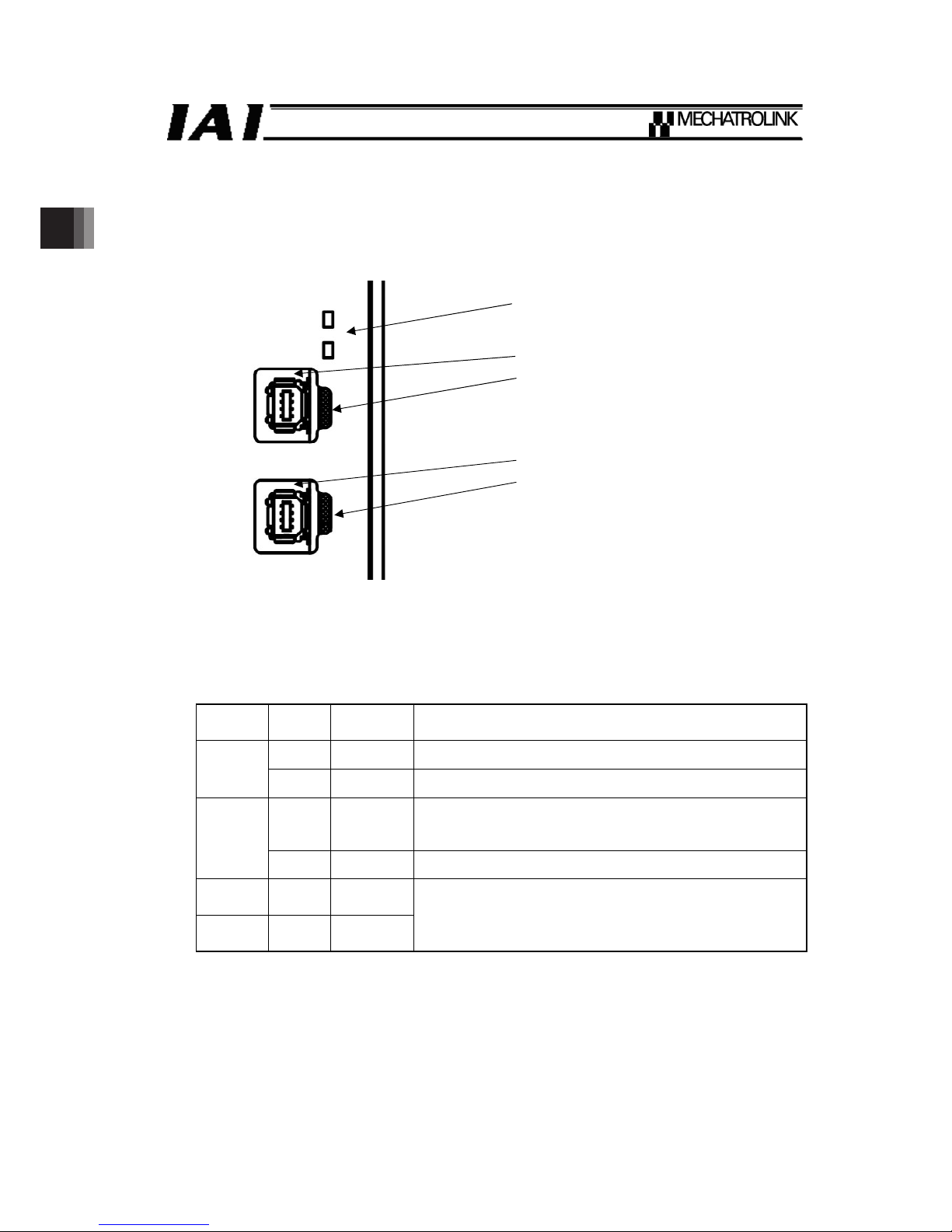
2.3 MECHATROLINK-䜕 Interface
2.3.1 Name of Each Part
The name of each part relating to MECHATROLINK-䜕 is shown.䎃
2.3.2 Status LED Indicators
The operation condition of the communication board, as well as the network condition, can be
checked using the two LEDs provided on the front side of the board.
LED Color
Indicator
condition
Description
Green Illuminating CONNECT received (Connected to the master)
CON
- OFF The board is not connected to the master unit
Orange Illuminating
Turns on when communication alarm or command alarm is
generated (warning excepted)
Turns off when alarm condition is cleard
ERR
- OFF In normal condition (alarm not generated)
LK1
(Link 1)
Green Illuminating
LK2
(Link 2)
Green OFF
Turns on when physically connected to another device
applicable for MECHATROLINK-䜕 (for purpose of error
check such as wire damage)
Status LED
Upstream Side Connector
LK1 (Link 1) LED
Downstream Side Connector
LK2 (Link 2) LED
CON
ERR
Page 19
2. SCON-CA
13
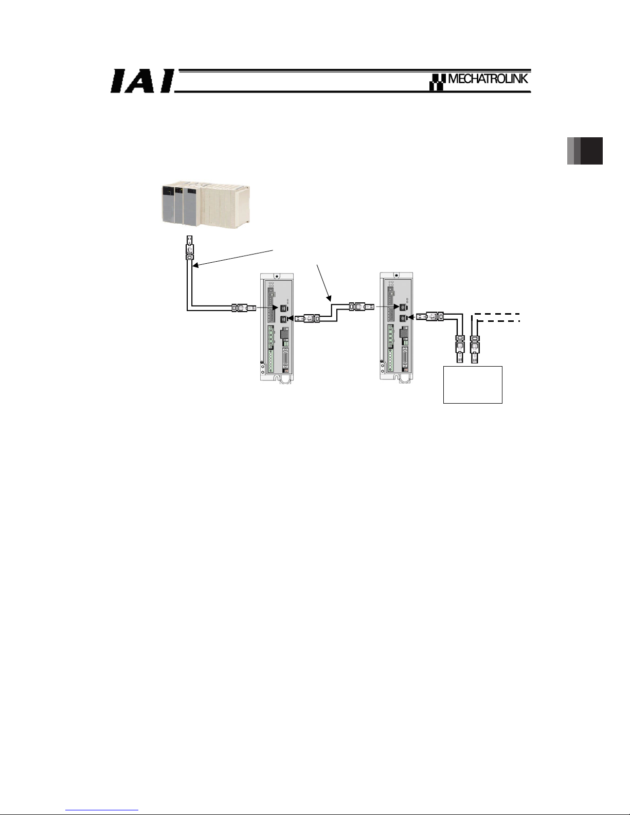
2.4 Example of Wiring
PLC
(MECHATROLINK-䜕
Master unit)
Slave unit
SCON-CA-ML3
Cable exclusively for
MECHATROLINK-䜕
SCON-CA-ML3
Cable exclusively for
MECHATROLINK-䜕
Page 20

2. SCON-CA
14
2.5 Setting
2.5.1 Node Address Setting
Set the node address using a parameter.
Set parameter No. 85, “NADR; Fieldbus node address” using the RC PC software.
(Refer to “MECHATROLINK-䜕 Parameters.”)
Settable range: 3 to 239 (The factory setting is 3.)
(Note) Pay attention to duplicate node address settings.
For more details, refer to the operation manual for the master unit or the PLC that is
installed.
2.5.2 Data length Setting
Set a desired data length using a parameter.
Establish the setting considering the data length which uses Parameter No. 86 “FBRS; Fieldbus
Communication Speed” in the RC PC software.
(Refer to “MECHATROLINK-䜕 Parameters.”)
Set value Data length Baud rate
0 32bytes
1
(factory setting)
48bytes
100Mbps
* If a greater value is entered, an parameter error will occur.
2.5.3 Setting of Electronic Gear Ratio
The electronic gear ratio is set with parameters.
Set the values in Parameter No. 65 “CNUM; Electronic Gear Numerator” and No. 66 “CDEN;
Electronic Gear Denominator” in the RC PC software. (Refer to “MECHATROLINK-䜕
Parameters.”)
The value set in these parameters controls the actuator by doing multiplication to the command
from the master.
Therefore, it is necessary to establish the setting that matches to the unit of master commands. In
case the unit of commands is unclear, change the value little by little from the initial. Also, it is
recommended, if there is a function to convert the unit or set up the gear ratio on the master, to
have the parameters set to 1/1 and make an adjustment on the master side.
Make sure the conditions stated below can be satisfied, and establish the setting.
Electronic gear
Stroke [mm] denominator
Ball screw lead length [mm] Electronic gear
numerator
2.5.4 Check for Direction of Pulse Count
The direction of pulse count can be set in parameters.
Check that the setting value in Parameter No. 62 “FPIO; Pulse count direction” is the same as that
in Parameter No. 5 “ORG; Home-return Direction” in the RC PC software, and make it the same in
case the different setting is made. (Refer to “MECHATROLINK-䜕 Parameters.”)
×
Encoder pulse number [pulse] ×
2
31
Page 21

3. Flow and Commands of Basic MECHATROLINK Communication
15
3. Flow and Commands of Basic MECHATROLINK
Communication
3.1 State Transition
Shown below is the state transition diagram.
Start
ω
Power Supply
ω
P1: Awaiting for connection
establishment
ω
ω
P2: Non-synchronous
communication condition
ω
ω
P3: Synchronous communication
condition
* P1 to P3: Communication Phase
* For details, refer to the operation manual for the MECHATROLINK master unit.
Master Sending
DISCONNECT Command from
master to RC controller
Master Sending CONNECT
Command from master to RC controller
(P2: Transition to non-synchronous
communication condition)
Master Sending
DISCONNECT Command from
master to RC controller
Communication
error
Master Sending SYNC_SET
Command from master to RC controller
(P3: Transition to synchronous
communication condition)
Page 22

3. Flow and Commands of Basic MECHATROLINK Communication
16
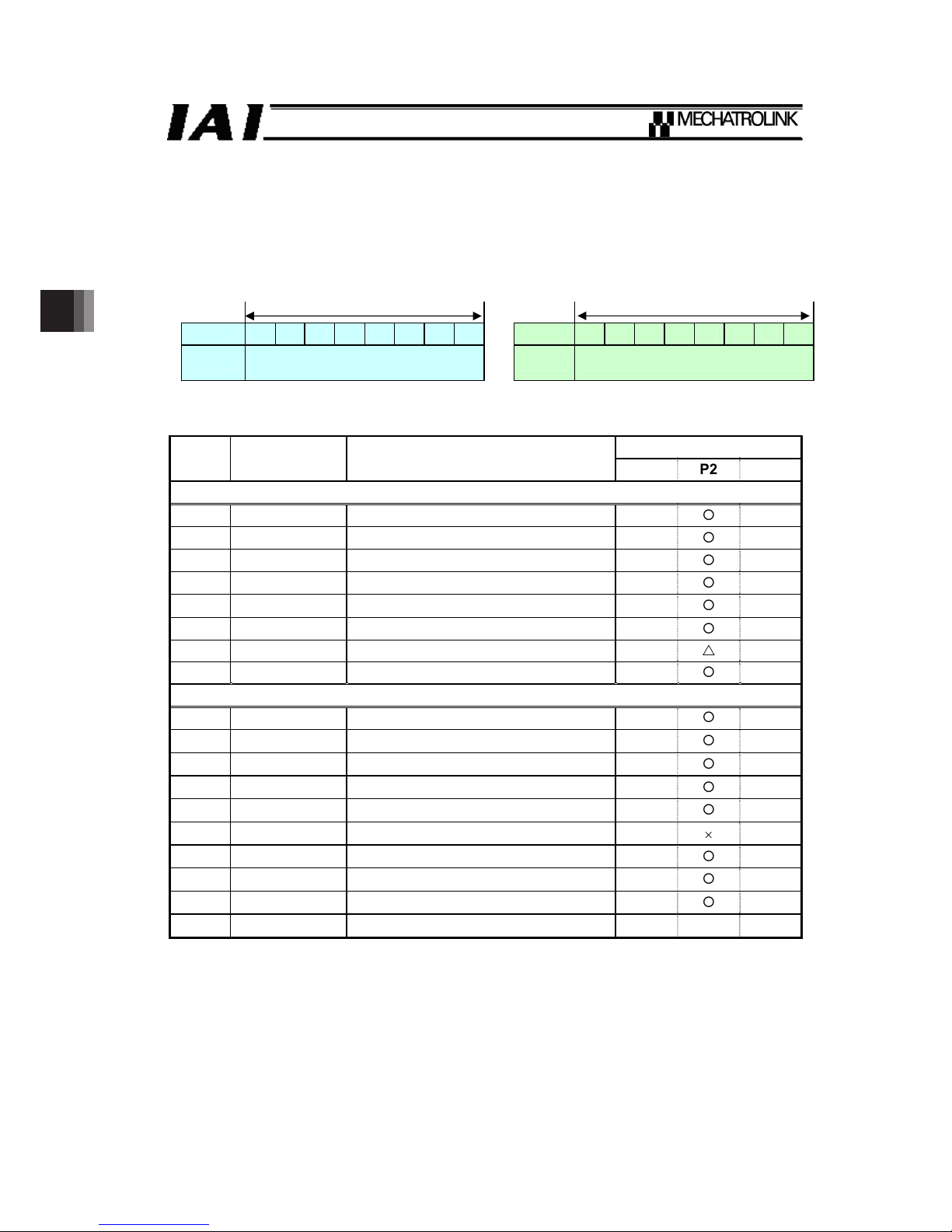
3.2 Command Frame Construction and Number of Transmission
Bytes
The command frame consists of the combination of the main command and the sub command.
Match the number of the transmission bytes to the setting on the host (master) side.
32-byte Mode is available only in the main command.
48-byte Mode is available not only in the main command, but also in the sub command. Also, it is
available not to have the sub command used with 48-byte Mode.
Byte 0 31 32 47
3.3 Endian
If there is the setting of endian on the master side, set to little endian on the master side.
3.4 System of Units
Shown below is the system of units for the data used in the standard servo profile command.
Data Available Unit
Speed Command unit/s × 10
0
Position Command unit × 10
0
Acceleration•Deceleration Command unit/s
2
× 10
0
Torque
Rated torque in % × 10
0
Main command (32 bytes) Sub command (16 bytes)
Page 23

4. Command Format
17
4. Command Format
The command frame consists of the combination of main command (32 bytes) and the sub
command (16 bytes). The sub command is to be used when adding another command to the main
command.
When using the sub command, set to 48 bytes for the number of the transmission bytes on the
master side.
Command byte Response byte
Command Code
(CMD)
0
Command Code Response
(RCMD)
0
Watchdog Data
(WDT)
1
Watchdog Status
(RWDT)
1
2 2
Command Control
(CMD_CTRL)
3
Command Status
(CMD_STAT)
3
4 4
5 5
6 6
7 7
8 8
9 9
1 0 1 0
11 11
1 2 1 2
1 3 1 3
1 4 1 4
1 5 1 5
1 6 1 6
1 7 1 7
1 8 1 8
1 9 1 9
2 0 2 0
2 1 2 1
2 2 2 2
2 3 2 3
2 4 2 4
2 5 2 5
2 6 2 6
2 7 2 7
2 8 2 8
2 9 2 9
3 0 3 0
Main
Command
Command Data
(CMD_DATA)
3 1
Response Data
(RSP_DATA)
3 1
Sub Command Code
(SUB_CMD)
3 2
Sub Command Code
Response
(SUB_RCMD)
3 2
3 3 3 3
3 4 3 4
Sub Command Control
(SUB_CTRL)
3 5
Sub Command Status
(SUB_STAT)
3 5
3 6 3 6
3 7 3 7
3 8 3 8
3 9 3 9
4 0 4 0
4 1 4 1
4 2 4 2
4 3 4 3
4 4 4 4
4 5 4 5
4 6 4 6
Sub
Command
Sub Command Data
(SUB_CMD_DATA)
4 7
Sub Response Data
(SUB_RSP_DATA)
4 7
Page 24
4. Command Format
18
4.1 Command / Response Frame
4.1.1 Command Code / Command Code Response (CMD/RCMD)
Select a command available to conduct from the table below by following the communication flow.
Command Format 0th Byte
Command Response
1 byte = 8 bits 1 byte = 8 bits
7 6 5 4 3 2 1 0 7 6 5 4 3 2 1 0
CMD
Select and set a code from table
below
RCMD Same value as CMD is to be replied
Example) For SV_ON Code 31
H
ψ Set value 0011 0001
b
{: Available to conduct, U: Ignored, u: Unavailable to conduct
Communication Phase
*1
Code Command Functions
P1 P2 P3
Common Commands
00H NOP Invalid
{ { {
03H ID_RD ID Reading
u
{ {
04H CONFIG Device Setup Request
u
{ {
05H ALM_RD Alarm / Warning Reading
u
{ {
06H ALM_CLR Alarm / Warning Cleared
u
{ {
0DH SYNC_SET Synchronization Establishment Request
u
{
U
0EH CONNECT Connection Establishment Request
{
U U
0FH DISCONNECT Connection Release Request
{ { {
Standard Servo Profile Commands
23H SENS_ON Sensor-on Request
u
{ {
24H SENS_OFF Sensor-off Request
u
{ {
30H SMON Servo Status Monitor
u
{ {
31H SV_ON Servo ON
u
{ {
32H SV_OFF Servo OFF
u
{ {
34H INTERPOLATE Interpolation Feeding
u u
{
35H POSING Positioning
u
{ {
36H FEED Constant Speed Feeding
u
{ {
40H SVPRM_RD Servo Parameter Reading
u
{ {
41H SVPRM_WR Servo Parameter Writing
u
{ {
*1 Communication Phase: this shows the current status of communication. There are three
types of status, P1 to P3.
[Refer to 3.1, “State Transition”]
Note 1 The unit is not applicable for the commands except for those listed in the table above.
It will generate an alarm [CMD_ALM = 8] when a command other than those listed in
the table above is received.
Note 2 Even a command listed in the table above may generate an alarm [CMD_ALM = C] if it
is received in a communication phase that the command cannot be used (where
marked with “u”).
Page 25

4. Command Format
19
4.1.2 Watchdog Data (WDT/RWDT)
Set the timer to monitor the communication is conducted periodically.
Monitoring starts after the communication phase P3 is established.
Command Format 1st Byte
Command Response
1 byte = 8 bits 1 byte = 8 bits
7 6 5 4 3 2 1 0 7 6 5 4 3 2 1 0
WDT
Copy the values
in Bit 7 to 4 in
RWDT
Add 1 for every
communication
frequency.
RWDT
1 is added for every
communication
frequency
Values in Bit 3 to
0 in WDT are to
be replied
4.1.3 Command Control / Command Status (CMD_CTRL/CMD_STAT)
Clearing of alarm / warning is commanded, and the current status of the controller is monitored.
(1) Command Control
Command Format 2nd and 3rd Bytes
Command format 3rd byte
Command format 2nd byte
1 byte = 8 bits
1 byte = 8 bits
15 14 13 12 11 10 9 8 7 6 5 4 3 2 1 0
CMD_CTRL Reserved
CMD
_ID
(Not
used)
Reserved
ALM
_CLR
Reserved
z ALM_CLR (Alarm and Warning Clear) :
Generates an alarm when startup edge is detected, or clearing of warning is commanded.
If the operation mode on the controller is set to AUTO, command to clear the alarm / warning
occurred to the controller including the communication. For MANU, the command is subject to clear
the alarm / warning related only to the communication.
Page 26

4. Command Format
20
(2) Command Status
Command Format 2nd and 3rd Bytes
Command format 3rd byte Command format 2nd byte
1 byte = 8 bits㩷 1 byte = 8 bits
15 14 13 12 11 10 9 8 7 6 5 4 3 2 1 0
CMD_STAT COMM_ALM CMD_ALM
CMD_ID
(Not
used)
Reserved
ALM
_CLR
CMP
CMD
RDY D_WAR D_ALM
Bits Abbreviations Names Contents
0 D_ALM Device Alarm
It shows the controller is in alarm condition.
The servo is off when this bit is 1.
1 D_WAR Device Warning
It shows the controller is in warning condition.
The servo control is available even when this bit is 1.
2 CMDRDY
Command
Ready
When 0, it shows the command process is being executed.
All the command inputs are ignored except for DISCONNECT
Command.
The master can issue a new command only after confirmed this
bit is 1.
3
ALM
_CLR
_CMP
Alarm / Warning
Clearing
Completed
This shows the execution of ALM_CLR in CMD_CTRL is
completed.
It shows the process is completed when this bit is 1. However, it
does not show if the alarm is actually cleard.
Check in D_ALM (Bit 0), D_WAR (Bit 1) or COMM_ALM (Bit 12
to 15) to see if the alarm is actually cleared.
4, 5 - Reserved
6, 7 CMD_ID Not used
It shows an abnormality in a command.
It is cleared automatically once a normal command is received.
Code
(bit 8 to
11)
Condition Contents Remarks
0
H
In normal
condition
In normal
condition
1H Warning
Out of data
range
Notifies a warning, and
have an operation with the
command value replaced
to the maximum value that
is available for operation.
8
H
Unsupported
command
received
9
H
Out of data
range
A
H
Command
execution
condition error
B
H
Sub command
combination
error
It notifies an alarm. No
command is to be
executed.
8 to 11
CMD
_ALM
Command
Alarm
C
H
Alarm
Phase error
Page 27

4. Command Format
21
Bits Abbreviations Names Contents
It shows an abnormality in communication.
It can be cleared with ALM_CLR Bit or ALM_CLR Command in
CMD_CTRL.
Code
(bit 8
to 11)
Condition Contents Remarks
0
H
In normal
condition
In normal
condition
1H FCS error
2
H
Command
data not
received
3
H
Warning
Synchronizing
frame not
received
It occurs when a
communication error in
spot is detected.
Communication phase and
servo status are continued.
8H FCS error
9
H
Command
data not
received
A
H
Synchronizing
frame not
received
B
H
Synchronizing
frequency
error
12 to
15
COMM
_ALM
Communication
Alarm
C
H
Alarm
WDT error
It occurs when
communication error is
detected for the indicated
times in a row.
It will be transited to
Communication Phase P2
if it is Communication
Phase P3.
An alarm is generated
when the warning of 1 to 3
above is detected for two
times in a row for Alarm
Code 8 to A.
An alarm is generated with
one time of detection for
Alarm Code B and C.
When the controller is in
AUTO Mode, the brake is
activated with the servo
being turned off.
4.1.4 Command Data / Respons Data (CMD_DATA/RSP_DATA)
Establish the necessary command settings considering the operation. [Refer to 5.1, “Main
Command”]
(1) Command Data
Command format 4th to 31st bytes
(2) Response Data
Command format 4th to 31st bytes
Page 28

4. Command Format
22
4.1.5 Sub Command Code / Sub Command Code Response
(SUB_CMD/SUB_RCMD)
Select a sub command available to conduct from the table below by following the communication
flow. At that time, check on the combination table of the main commands and sub commands that
the selected sub command is available for combination with the main command.
Command format 32nd
Command Response
1 byte = 8 bits㩷
㩷 㩷
1 byte = 8 bits
7 6 5 4 3 2 1 0 7 6 5 4 3 2 1 0
SUB_
CMD
Select and set a code from table
below
SUB_
RCMD
Same value as SUB_CMD is to be
replied
{: Available to conduct, u: Unavailable to conduct
Communication Phase
Code Command Functions
P1 P2 P3
Standard Servo Profile Sub Commands
00H NOP Ignored
u
{ {
05H ALM_RD Alarm / Warning Reading
u
{ {
30H SMON Servo Status Monitor
u
{ {
Note 1 The unit is not applicable for the sub commands except for those listed in the table
above. An alarm [SUBCMD_ALM = 8] is generated when combination is not available
with the sub command or main command listed in the table above.
Note 2 When receiving is conducted on the communication phase (P1), the sub command
cannot be accepted. There will be no alarm generated in that case.
z Combination of Main Command and Sub Command
{: Combination available, u: Combination Unavailable
Sub Command
Main Command
NOP(00
H
) ALM_RD(05H) SMON(30H)
NOP(00H)
{ { {
ID_RD(03H)
{ { {
CONFIG(04H)
{ { {
ALM_RD(05H)
{ { {
ALM_CLR(06H)
{ { {
SYNC_SET(0DH)
{ { {
CONNECT(0EH)
{
u u
DISCONNECT(0FH)
{
u u
SENS_ON(23H)
{ { {
SENS_OFF(24H)
{ { {
SMON(30H)
{ { {
SV_ON(31H)
{ { {
SV_OFF(32H)
{ { {
INTERPOLATE(34H)
{ { {
POSING(35H)
{ { {
FEED(36H)
{ { {
SVPRM_RD(40H)
{ { {
SVPRM_WR(41H)
{ { {
Page 29

4. Command Format
23
4.1.6 Sub Command Control / Sub Command Status (SUB_CTRL/SUB_STAT)
Select the monitor data to have the readout from the monitor information and select a code.
(1) Sub Command Control
Command Format 33rd to 35th Bytes
Command format 34th byte Command format 33rd byte
1 byte = 8 bits㩷 1 byte = 8 bits㩷
15 14 13 12 11 10 9 8 7 6 5 4 3 2 1 0
SUB_CTRL SEL_MON4 Reserved Reserved
Command format 35th byte
1 byte = 8 bits㩷
23 22 21 20 19 18 17 16
SUB_CTRL SEL_MON6 SEL_MON5
Monitor Information
Code Monitor Name Contents Remarks
0H APOS Feedback position
1H CPOS Command position
2H PERR Position deviation
3, 4H - Reserved
5H FSPD Feedback speed
6H CSPD Command speed
7H TRQ Command torque (Thrust)
8
H
ALARM
Detailed information for alarm
currently generated
It shows the warning on controller or
alarm code
9
H
MPOS Command position
It should be the same value as
CPOS (Code 1)
A, BH - Reserved
C
H
CMN1 Common monitor 1
It is to be indicated in Common
Parameter No. 89
D
H
CMN2 Common monitor 2
It is to be indicated in Common
Parameter No. 8A
E, FH - Reserved
Page 30

4. Command Format
24
(2) Sub Command Status
Command Format 33rd to 35th Bytes
Command format 34th byte Command format 33rd byte
1 byte = 8 bits 1 byte = 8 bits
15 14 13 12 11 10 9 8 7 6 5 4 3 2 1 0
SUB_STAT SEL_MON4 SUBCMD_ALM Reserved
SUB
CMD
RDY
Reserved
Command format 35th byte
1 byte = 8 bits㩷
23 22 21 20 19 18 17 16
SUB_STAT SEL_MON6 SEL_MON5
Bits Abbreviations Names Contents
0, 1 - Reserved
2 SUBCMDRDY
Sub Command
Ready
It shows this bit is 1 and the sub command can be
accepted.
In 48-Byte Mode, this is always one no matter if the
sub command is valid or invalid after the connection
is established with CONNECT Command.
3 to 7 - Reserved
8 to 11 SUBCMD_ALM
Sub Command
Alarm
It shows an abnormality in a command.
It is cleared automatically once a normal command
is received.
[Refer to section 4.1.3(2) for detail of the alarm
code]
12 to 15 SEL_MON4 Monitor Select 4
The value set in SEL_MON4 in SUB_CTRL is to be
replied.
16 to 19 SEL_MON5 Monitor Select 5
The value set in SEL_MON5 in SUB_CTRL is to be
replied.
20 to 23 SEL_MON6 Monitor Select 6
The value set in SEL_MON6 in SUB_CTRL is to be
replied.
4.1.7 Sub Command Data / Sub Response Data
(SUB_CMD_DATA/SUB_RSP_DATA)
Establish the necessary sub command settings considering the operation. [Refer to section
5.2, “Sub Command”]
(1) Sub Command Data
Command Format 36th to 47th Bytes
(2) Sub Response Data
Command Format 36th to 47th Bytes
Page 31

5. Command
25
5. Command
5.1 Main Command
5.1.1 Specifications of Common Commands
5.1.1.1 Invalid (NOP Code: 00H)
It is an invalid command.
Current condition is replied as a response.
The response from the power turned on till the completion of the initializing process is NOP, and no
command but DISCONNECT can be received.
ƔNOP
Bytes of
Command
Format
Command Response Remarks
0 00
H
00
H
1 WDT RWDT
[Refer to section
4.1.2.]
2
3
CMD_CTRL CMD_STAT
[Refer to section
4.1.3.]
4 to 31 Reserved Reserved
Page 32

5. Command
26
5.1.1.2 ID Reading (ID_RD Code: 03 H)
Readout is held on each ID of the controller.
Set the ID code to be read out in ID_CODE.
An alarm will be generated and will not accept any command in the following cases:
1) Indicated value in ID_CODE is out of the range in ID Code Table. (It generates CMD_ALM = 9)
2) The range shown in OFFSET and SIZE exceeds the range of ID data for readout. (It generates
CMD_ALM = 9)
3) SIZE exceeds 24 bytes. (It generates CMD_ALM = 9)
4) The range of OFFSET exceeds the range of ID data for readout. (It generates CMD_ALM = 9)
ƔID_RD
Bytes of
Command
Format
Command Response Remarks
0 03
H
03
H
1 WDT RWDT
[Refer to section
4.1.2.]
2
3
CMD_CTRL CMD_STAT
[Refer to section
4.1.3.]
4
ID_CODE ID_CODE
5 OFFSET OFFSET
If OFFSET is set, only
the indicated size can
be read out on the way
of ID data
6
7
SIZE SIZE
8 to 31 Reserved ID
Details of ID data
ID Code Description
Data Size
[bytes]
Data type Data
01H Vendor ID Code 4 Binary 000000CA
H
02
H
Device Code
(Model Code)
4 Binary 0000****
H
03
H
Device Version
(Version Code on Application)
4 Binary 0000****
H
04
H
Device Information File
Version
4 Binary 00001000
H
05
H
Extension Address Setting
(Number of Used Extension
Addresses)
4 Binary 00000001
H
06H Serial number 32
ASCII Code
(Delimiter = 00H)
Serial number on
controller
10
H
Profile Type 1
(Primary)
4 Binary
00000010
H
(Standard servo)
11
H
Profile Version 1
(Primary)
4 Binary
00000100
H
(V1.00)
12H Profile Type 2 4 Binary
000000FF
H
(Not applicable)
13H Profile Version 2 4 Binary 00000000
H
14H Profile Type 3 4 Binary
000000FF
H
(Not applicable)
Page 33

5. Command
27
ID Code Description
Data Size
[bytes]
Data type Data
15H Profile Version 3 4 Binary 00000000
H
16
H
Min. Transmission Frequency
(0.01ȝs)
4 Binary
0000C350
H
(0.5ms)
17
H
Max. Transmission Frequency
(0.01ȝs)
4 Binary
00061A80
H
(4ms)
18
H
Transmission Frequency
Intervals
(GRANULARITY)
4 Binary
00000002
H
(0.5ms)
19
H
Min. Communication
Frequency (0.01ȝs)
4 Binary
0000C350
H
(0.5ms)
1A
H
Max. Communication
Frequency (0.01ȝs)
4 Binary
0030D400
H
(4ms)
1B
H
Number of Transmission
Bytes
(Applicable Bit Patterns)
4 Binary
0000000C
H
(32 or 48 bytes)
1C
H
Number of Transmission
Bytes
(Current Settings)
4 Binary
Number of bytes set in
parameter
1D
H
Profile Type
(Current Selections)
4 Binary
20
H
Communication Mode
Correspondence
4 Binary
00000003
H
(Cyclic communication
Event-driven
communication)
21H Reserved -
30
H
Main Command
Correspondence List
32 Array[32]
[0] = 79
H
[1] = E0
H
[2] = 00H [3] = 00
H
[4] = 18H [5] = 00
H
[6] = 77H [7] = 00
H
[8] = 03
H
[9] to [31] = 00
H
38
H
Sub Command
Correspondence List
32 Array[32]
[0] = 21
H
[1] = 00
H
[2] = 00H [3] = 00
H
[4] = 00H [5] = 00
H
[6] = 01
H
[7] to [31] =00
H
40
H
Common Parameter
Correspondence List
32 Array[32]
[0] = FE
H
[1] = 1F
H
[2] = 00H [3] = 00
H
[4] = 66H [5] = 01
H
[6] = 00H [7] = 00
H
[8] = FEH [9] = 03
H
[10] = 00H [11] = 00
H
[12] = C0H [13] = 00
H
[14] = 00H [15] = 00
H
[16] = 80H [17] = 4F
H
[18] = 0F
H
[19] to [31] = 00
H
80
H
Main Device Name
(Controller Product Name)
32
ASCII Code
(Delimiter = 00H)
“SCON-CA-ML3”
81H to Reserved -
Page 34

5. Command
28
5.1.1.3 Device Setup Request (CONFIG Code: 04H)
It is the recalculation of common parameters and setup request command.
CONFIG_MOD is applicable only for 0. It generates an alarm for others and command will not be
accepted. (It generates CMD_ALM = 9)
ƔCONFIG
Bytes of
Command
Format
Command Response Remarks
0 04
H
04
H
1 WDT RWDT
[Refer to section
4.1.2.]
2
3
CMD_CTRL CMD_STAT
[Refer to section
4.1.3.]
4
CONFIG_MOD CONFIG_MOD
Applicable only for 0
5 to 31 Reserved Reserved
Page 35

5. Command
29
5.1.1.4 Alarm / Warning Readout (ALM_RD Code: 05H)
It is the readout command for the alarms and warnings on the controller.
If ALM_RD_MOD is set to 0, the readout of the alarm code currently generated is conducted. The
read out alarm code is stored in Bytes 8 and 9 in the response. When the read out alarm data is 0,
it shows that there is no alarm generated.
When ALM_RD_MOD is set to 3, the alarm history in the number set in ALM_INDEX *1 is read out.
*1 The setting range for ALM_INDEX is 0 to 15. (0 is the latest alarm)
An alarm will be generated and will not accept any command in the following cases:
1) A number other than 0 or 3 is set in ALM_RD_MOD. (It generates CMD_ALM = 9)
2) 3 is set in ALM_RD_MOD and a number out of the range is set in ALM_INDEX. (It generates
CMD_ALM = 9)
ƔALM_RD
Bytes of
Command
Format
Command Response Remarks
0 05
H
05
H
1 WDT RWDT
[Refer to section
4.1.2.]
2
3
CMD_CTRL CMD_STAT
[Refer to section
4.1.3.]
4
5
ALM_RD_MOD ALM_RD_MOD Refer to table below
6
7
ALM_INDEX ALM_INDEX 0 to 15 (0 = Latest)
8 to 31
Reserved ALM_DATA
Details of ALM_DATA (For ALM_RD_MOD=3)
Bytes Contents Remarks
8
9
Alarm Code
Refer to SCON-CA Instruction Manual provided separately for the
details of alarm code
10, 11 Reserved
12
13
Alarm Occurrence
Address
The address is the resistor address inside the controller.
(Address is invalid when FFFF
H
)
14
15
Alarm Detail Code The contents of the detail code differ for each alarm code.
16
17
18
19
Alarm Occurrence
Clock
If the time setting is activated by turning on the calendar function in
Controller Parameter No. 111, it shows the year, month, day and time of
the alarm occurrence.
If the calendar function is set inactivated in Controller Parameter No.
111, or if the calendar function is set valid, but no clock setting is
performed, the timing when the power is turned on to the controller is
identified as 00/01/01 00:00:00.
Page 36

5. Command
30
5.1.1.5 Alarm / Warning Clear (ALM_CLR Code: 06H)
It executes the alarm / warning clearing command.
An alarm currently being generated is available to clear. (Applicable only for ALM_CLR_MOD = 0)
When the operation mode of the controller is set to AUTO, a command is executed to clear alarm /
warning being generated on the controller including the communication. When MANU, a command
is executed to clear alarm / warning related the communication.
ALM_CLR_MOD is applicable only to 0. It generates an alarm for others and command will not be
accepted. (It generates CMD_ALM = 9)
ƔALM_CLR
Bytes of
Command
Format
Command Response Remarks
0 06
H
06
H
1 WDT RWDT
[Refer to section
4.1.2.]
2
3
CMD_CTRL CMD_STAT
[Refer to section
4.1.3.]
4
5
ALM_CLR_MOD ALM_CLR_MOD Applicable only for 0
6 to 31 Reserved Reserved
5.1.1.6 Synchronization Establishment Request (SYNC_SET Code: 0DH)
It is a command to start the synchronizing communication and request a transition to the
communication phase P3.
This command will be ignored if it is executed in a condition that it is already in the communication
phase P3.(There is no alarm or warning to be generated.)
ƔSYNC_SET
Bytes of
Command
Format
Command Response Remarks
0 0D
H
0D
H
1 WDT RWDT
[Refer to section
4.1.2.]
2
3
CMD_CTRL CMD_STAT
[Refer to section
4.1.3.]
4 to 31 Reserved Reserved
Page 37

5. Command
31
5.1.1.7 Connection Establishment Request (CONNECT Code: 0EH)
It is a command to request the establishment of the communication (connection).
This command will be ignored if it is executed in a condition of being in the communication phase
P2 or P3. (There is no alarm or warning to be generated.)
An alarm will be generated and will not accept any command in the following cases:
1) A value other than 30
H
is set to VER (It generates CMD_ALM = 9)
2) A value other than 0 is set to DTMODE in COM_MODE (It generates CMD_ALM = 9)
3) When in setting of 32-byte Mode, 1 is set to SUBCMD in COM _MODE (It generates
CMD_ALM = 9)
4) A value out of the range of 0.5 to 32ms is set in the communication frequency (Transmission
frequency x COM_TIME) (It generates CMD_ALM = 9)
5) A value other than 10
H
is set in PROFILE_TYPE (It generates CMD_ALM = 9)
ƔCONNECT
Bytes of
Command
Format
Command Response Remarks
0 0E
H
0E
H
1 WDT RWDT
[Refer to section
4.1.2.]
2
3
CMD_CTRL CMD_STAT
[Refer to section
4.1.3.]
4 VER VER Fixed at 30
H
5
COM_MODE COM_MODE
Refer to table below
6 COM_TIME COM_TIME
Establish setting to
determine how many
times of transmission
frequency is to be the
communication
frequency
7
PROFILE_TYPE PROFILE_TYPE
Fixed at 10
H
8 to 31 Reserved Reserved
Details of COM_MODE Field
Bits Abbreviations Names Contents
0 - Reserved
1
SYNC
MODE
Synchronizing
Setting
0: Non-synchronizing communication (Transited to
communication phase P2)
1: Synchronizing communication (Transited to
communication phase P3)
2
3
DTMODE
Communication
System
0: Single transmission communication
1: Continuous transmission communication (Not
supported)
4 to 6 - Reserved
7 SUBCMD
Sub Command
Setting
0: Sub command inactivated
1: Sub command activated
Page 38

5. Command
32
5.1.1.8 Connection Release Request (DISCONNECT Code: 0FH)
It is a command to request the transition to the communication phase P1 by releasing the
communication (connection).
This command is available in any condition.
When the operation mode of the controller is in AUTO, the brake is activated with the servo being
turned off once this command is executed.
ƔDISCONNECT
Bytes of
Command
Format
Command Response Remarks
0 0F
H
0F
H
1 WDT RWDT
[Refer to section
4.1.2.]
2
3
CMD_CTRL CMD_STAT
[Refer to section
4.1.3.]
4 to 31 Reserved Reserved
Page 39

5. Command
33
5.1.2 Specifications of Standard Servo Profile Commands
5.1.2.1 Servo Status Monitor (SMON Code: 30H)
It is a command to read out the home-return command and monitor information.
ƔSMON
Bytes of
Command
Format
Command Response Remarks
0 30
H
30
H
1 WDT RWDT
[Refer to section
4.1.2.]
2
3
CMD_CTRL CMD_STAT
[Refer to section
4.1.3.]
4
5
6
7
SVCMD_CTRL
[Refer to Pg34, “Details
of SVCMD_CTRL
Field"]
SVCMD_STAT
[Refer to Pg35, “Details
of SVCMD_STAT
Field"]
㩷
8
9
10
11
SVCMD_IO
[Refer to Pg36, “Details
of SVCMD_IO
Command Field”]
SVCMD_IO
[Refer to Pg37, “Details
of SVCMD_IO
Response Field”]
㩷
12
13
14
15
CPRM_SEL_MON1
Selected in Common
Parameter No. 87
[Refer to section 5.3.]
16
17
18
19
CPRM_SEL_MON2
Selected in Common
Parameter No. 88
[Refer to section 5.3.]
20
21
22
23
MONITOR1
24
25
26
27
MONITOR2
28
29
30
31
Reserved
MONITOR3
Refer to Pg34, “Details
of SVCMD_CTRL
Field" and Pg38,
“Monitor Information”
Page 40

5. Command
34
Details of SVCMD_CTRL Field
Bits Abbreviations Names Contents
0 CMD_PAUSE
Movement
Command Pause
0: None
1: Pause
It is available only during POSING, FEED Command
or home-return operation. The previous condition is
continued in other cases. Because the target
position is not changed, a pause during an
operation does not complete the discharge (DEN =
1). [Refer to Pg37 “Details of SVCMD_IO Response
Field”]
When issued at the same time as CMD_CANCEL,
CMD_CANCEL will be prioritized.
It will be ignored when the operation mode of the
controller is in MANU.
1 CMD_CANCEL
Movement
Command Cancel
0: None
1: Movement is cancelled
It is available only during POSING, FEED Command
or home-return operation. The previous condition is
continued in other cases. Because the target
position is changed, Completion of the movement
cancel completes the discharge (DEN = 1). [Refer
to Pg37 “Details of SVCMD_IO Response Field”]
It will be ignored when the operation mode of the
controller is in MANU.
2, 3 STOP_MODE
Stop Mode
Selection
0: Deceleration and stop (recommended)
1: Sudden stop
This indicates the stop mode for CMD_PAUSE and
CMD_CANCEL above.
Do not attempt to set a number above 2.
It will be ignored when the operation mode of the
controller is in MANU.
Caution
For sudden stop, the target position is replaced to
the current command value to perform a stop.
However, CMD_CANCEL during the home-return
operation is a stop at the spot no matter what stop
mode is selected.
4 to 15 - Reserved
16 to
19
SEL_MON1 Monitor Select 1
Monitor code to be set in MONITOR1
[Refer to Pg38, “Monitor Information”]
20 to
23
SEL_MON2 Monitor Select 2
Monitor code to be set in MONITOR2
[Refer to Pg38, “Monitor Information”]
24 to
27
SEL_MOM3 Monitor Select 3
Monitor code to be set in MONITOR3
[Refer to Pg38, “Monitor Information”]
28 to
31
- Reserved
Page 41

5. Command
35
Details of SVCMD_STAT Field
Bits Abbreviations Names Contents
0
CMD_PAUSE_C
MP
Movement
Command Pause
Complete
0: None
1: Pause Completed
It shows the completion of pause commanded by
CMD_PAUSE [Refer to Pg34, “Details of
SVCMD_CTRL Field”]
It turns to 1 when CMD_PAUSE = 1 and zero
speed (ZSPD = 1) during POSING, FEED
Command or the home-return operation. [Refer to
Pg37, “Details of SVCMD_IO Response Field”]
1
CMD_CANCEL_C
MP
Movement
Command Cancel
Complete
0: None
1: Movement cancel completed
It shows the completion of movement cancel
commanded by CMD_CANCEL [Refer to Pg34,
“Details of SVCMD_CTRL Field”]
It turns to 1 when CMD_PAUSE = 1 and the
discharge is complete (DEN = 1) during POSING,
FEED Command or the home-return operation.
[Refer to Pg37, “Details of SVCMD_IO Response
Field”]
2 to 9 - Reserved
10 POS_RDY
Position Information
Valid
z For Absolute Encoder Type
0: Home-return incomplete
1: Home-return completed
It turns to 1 when absolute reset is complete
(home-return is complete).
z For Incremental Encoder Type
0: Condition of connection not being established
1: Condition of connection being established
It turns to 1 when CONNECT Command process
completes.
11 PON Main Power ON Always 1 is read out
12 M_RDY
Motor Conductivity
Ready
0: Driving source OFF
1: Driving source ON
13 SV_ON Servo ON
0: Servo OFF
1: Servo ON
The torque control value is the current control value
during movement of the controller parameter when
the servo is off.
14ޔ15 - Reserved
16 to 19 SEL_MON1 Monitor Select 1
The value set in SEL_MON1 of SVCMD_CTRL is
replied.
20 to 23 SEL_MON2 Monitor Select 2
The value set in SEL_MON2 of SVCMD_CTRL is
replied.
24 to 27 SEL_MON3 Monitor Select 3
The value set in SEL_MON3 of SVCMD_CTRL is
replied.
28 - Reserved
29 BALM Battery Alarm
0: ABS battery voltage in normal condition
1: ABS battery voltage low warning
30 DALM Driver Alarm
0: No alarm
1: Alarm being generated (warnings excluded)
31 - Reserved
Page 42

5. Command
36
Details of SVCMD_IO Command Field (Master Slave)
Bits Abbreviations Names Contents
0 to 7 - Reserved
8 to 11 G_SEL Gain Switchover
0 to 3: Servo gain set select
Select the servo gain set 0 to 3 in the controller
parameter.
Do not attempt to set to 4 or higher.
It is available only for INTERPOLATE, POSING
and FEED Commands, and is reflected
immediately if a command is being executed.
Home-return operation activates with the setting of
servo gain set 0.
It will be ignored when the operation mode of the
controller is in MANU.
12 to 15 - Reserved
16 BKRL
Brake Compulsory
Release
0: Not to have the brake compulsorily released
when the servo is off
1: To have the brake compulsorily released when
the servo is off
It will be ignored when the operation mode of the
controller is in MANU.
Caution
This bit is accepted even when the servo is on. In
case of the axis installed in vertical orientation, the
transported object or fixture may drop once the
servo is turned off in the condition of the brake
release command.
17 HOME Home-Return
Home-return operation starts when the startup
edge is detected.
The current control value at home-return and the
current control value at a movement after the
home-return operation are the controller parameter
value.
It will be ignored when the operation mode of the
controller is in MANU.
18 to 31 - Reserved
Page 43

5. Command
37
Details of SVCMD_IO Response Field (Slave Master)
Bits Abbreviations Names Contents
0, 1 - Reserved
2 P_OT
Input of Drive in
Positive Direction
Forbidden
3 N_OT
Input of Drive in
Negative Direction
Forbidden
Always 0 is read out.
4 to 6 - Reserved
7 ESTP Emergency Stop
0: Emergency stop released
1: In emergency stop condition
8 - Reserved
9 BRK_ON Brake Output
0: brake release
1: Brake lock
It shows the condition of Brake Release/Lock
Command. However, the condition of hardware
switches (such as the brake release switch on the
front of the controller) cannot be reflected.
10 P_SOT
Positive Side Soft
Limit
0: Current position is in positive side software limit
1: Current position exceeds positive side software
limit
11 N_SOT
Negative Side Soft
Limit
0: Current position is in negative side software limit
1: Current position exceeds negative side software
limit
12 DEN
Discharge Complete
(Position Control
Mode)
0: Position command output incomplete
1: Position command output completed
13 NEAR
Near Positioning
(Position Control
Mode)
0: Current position out of near positioning band
1: Current position in near positioning band
* Near positioning band initial setting = positioning
band initial setting in parameter
14 PSET
Positioning Complete
(Position Control
Mode)
0: DEN = 0 (Bit 12) or current position out of
positioning complete band
1: DEN = 1 and current position in positioning
complete band
* Positioning complete band initial setting =
positioning band initial setting in parameter
15 ZPOINT Home Position
0: Home-return incomplete or current position out of
home position detection band
1: Home-return completed and current position in
home position detection band
* Home position detection band initial setting =
positioning band initial setting in parameter
16 to 18 - Reserved
19 ZSPD Zero Speed
0: Current speed out of zero speed detection band
1: Current speed in zero speed detection band
20 to 23 - Reserved
24 OVLW Overload Warning
0: Operation in normal condition
1: Driver overload warning generated
25 HEND
Home-return
Completed
0: Home-return incomplete
1: Home-return completed
26 ZONE1 Zone 1
0: Current position out of ZONE1 range
1: Current position in ZONE1 range
* Because ZONE1 updates the status in the control
frequency of the controller, it may not synchronize
with the APOS of the monitor [Refer to Pg38,
“Monitor Information”].
Page 44

5. Command
38
Bits Abbreviations Names Contents
27 ZONE2 Zone 2
0: Current position out of ZONE2 range
1: Current position in ZONE2 range
* Because ZONE2 updates the status in the control
frequency of the controller, it may not synchronize
with the APOS of the monitor [Refer to Pg38,
“Monitor Information”].
28 RMDS Operation Mode
0:AUTO
1:MANU
29 to 31 - Reserved
Monitor Information
Code Monitor Name Contents Remarks
0H APOS Feedback Position
1H CPOS Command Position
2H PERR Position Deviation
3, 4H - Reserved
5H FSPD Feedback Speed
6H CSPD Command Speed
7H TRQ Command Torque (Thrust)
8
H
ALARM
Detailed Information for Alarm
Currently Generated
It shows the warning or alarm code
9
H
MPOS Command Position
It should be the same value as CPOS
(Code 1)
A, BH - Reserved
C
H
CMN1
Common Monitor 1
[Refer to the next table]
It is to be indicated in Common
Parameter No. 89
D
H
CMN2
Common Monitor 2
[Refer to the next table]
It is to be indicated in Common
Parameter No. 8A
E, FH - Reserved
Common Monitor Data List
Code Names Contents Units Symbol Remarks
0 TPOS Target Position Command unit Exist
1 IPOS
Instruction
Position
Command unit Exist
It is the same value as CPOS
(Code 1 in Monitor Information)
2 - Reserved
3 TSPD Target Speed Command unit /s None
4 - Reserved
5 TRQ_LIM Torque Limit % None
6 SV_STAT
Servo Actual
Operational
Status
- None
[0]: Communication Phase
[1]: Current control mode (0:
fixed to position control)
[2]: Reserve(fixed to 0)
[3]: Extension input signal
monitor
(Always all bits 0)
7 to 9 - Reserved
Page 45

5. Command
39
5.1.2.2 Sensor-on Request (SENS_ON Code: 23H)
It is the command to request the sensor (encoder) to turn ON. Since it is unable to turn on and off
the encoder power with a command, this just replies a normal response.
(The data except for Response Command (23
H
) is the same as section 5.1.2.1 SMON Command)
ƔSENS_ON
Bytes of
Command
Format
Command Response Remarks
0 23
H
23
H
1 WDT RWDT [Refer to section 4.1.2.]
2
3
CMD_CTRL CMD_STAT [Refer to section 4.1.3.]
4
5
6
7
SVCMD_CTRL
[Refer to section 5.1.2.1,
“Details of
SVCMD_CTRL Field”]
SVCMD_STAT
[Refer to section 5.1.2.1,
“Details of
SVCMD_STAT Field”]
㩷
8
9
10
11
SVCMD_IO
[Refer to section 5.1.2.1,
“Details of SVCMD_IO
Command Field”]
SVCMD_IO
[Refer to section 5.1.2.1,
“Details of SVCMD_IO
Response Field”]
㩷
12
13
14
15
CPRM_SEL_MON1
Selected in Common
Parameter No. 87
[Refer to section 5.3.]
16
17
18
19
CPRM_SEL_MON2
Selected in Common
Parameter No. 88
[Refer to section 5.3.]
20
21
22
23
MONITOR1
24
25
26
27
MONITOR2
28
29
30
31
Reserved
MONITOR3
Refer to section 5.1.2.1
“Details of
SVCMD_CTRL Field”
and “Monitor
Information”
Page 46

5. Command
40
5.1.2.3 Sensor-off Request (SENS_OFF Code: 24H)
It is the command to request the sensor (encoder) to turn OFF. Since it is unable to turn on and off
the encoder power with a command, this just replies a normal response.
(The data except for Response Command (24
H
) is the same as section 5.1.2.1 SMON Command)
ƔSENS_OFF
Bytes of
Command
Format
Command Response Remarks
0 24
H
24
H
1 WDT RWDT [Refer to section 4.1.2.]
2
3
CMD_CTRL CMD_STAT [Refer to section 4.1.3.]
4
5
6
7
SVCMD_CTRL
[Refer to section 5.1.2.1,
“Details of
SVCMD_CTRL Field”]
SVCMD_STAT
[Refer to section 5.1.2.1,
“Details of
SVCMD_STAT Field”]
㩷
8
9
10
11
SVCMD_IO
[Refer to section 5.1.2.1,
“Details of SVCMD_IO
Command Field”]
SVCMD_IO
[Refer to section 5.1.2.1,
“Details of SVCMD_IO
Response Field”]
㩷
12
13
14
15
CPRM_SEL_MON1
Selected in Common
Parameter No. 87
[Refer to section 5.3.]
16
17
18
19
CPRM_SEL_MON2
Selected in Common
Parameter No. 88
[Refer to section 5.3.]
20
21
22
23
MONITOR1
24
25
26
27
MONITOR2
28
29
30
31
Reserved
MONITOR3
Refer to section 5.1.2.1
“Details of
SVCMD_CTRL Field”
and “Monitor
Information”
Page 47

5. Command
41
5.1.2.4 Servo ON Request (SV_ON Code: 31H)
It is the command to request the servo to turn ON.
For the servo status, check SV_ON in SVCMD_STAT
(The data except for Response Command (31
H
) is the same as section 5.1.2.1 SMON Command)
An alarm will be generated and will not accept any command in the following cases:
1) Alarm is generated on the controller (It generates CMD_ALM = A)
2) In emergency stop condition (It generates CMD_ALM = A)
3) Communication alarm is generated (COMM_ALM 8) (It generates CMD_ALM = A)
4) The operation mode of the controller is MANU mode (It generates CMD_ALM = A)
ƔSV_ON
Bytes of
Command
Format
Command Response Remarks
0 31
H
31
H
1 WDT RWDT
[Refer to section
4.1.2.]
2
3
CMD_CTRL CMD_STAT
[Refer to section
4.1.3.]
4
5
6
7
SVCMD_CTRL
[Refer to section 5.1.2.1,
“Details of
SVCMD_CTRL Field”]
SVCMD_STAT
[Refer to section 5.1.2.1,
“Details of SVCMD_STAT
Field”]
㩷
8
9
10
11
SVCMD_IO
[Refer to section 5.1.2.1,
“Details of SVCMD_IO
Command Field”]
SVCMD_IO
[Refer to section 5.1.2.1,
“Details of SVCMD_IO
Response Field”]
㩷
12
13
14
15
CPRM_SEL_MON1
Selected in Common
Parameter No. 87
[Refer to section 5.3.]
16
17
18
19
CPRM_SEL_MON2
Selected in Common
Parameter No. 88
[Refer to section 5.3.]
20
21
22
23
MONITOR1
24
25
26
27
MONITOR2
28
29
30
31
Reserved
MONITOR3
Refer to section
5.1.2.1 “Details of
SVCMD_CTRL Field”
and “Monitor
Information”
Page 48

5. Command
42
5.1.2.5 Servo OFF Request (SV_OFF Code: 32H)
It is the command to request the servo to turn OFF.
For the servo status, check SV_ON in SVCMD_STAT
(The data except for Response Command (32
H
) is the same as section 5.1.2.1 SMON Command)
An alarm will be generated and will not accept any command in the following cases:
• The operation mode of the controller is MANU mode (It generates CMD_ALM = A)
ƔSV_OFF
Bytes of
Command
Format
Command Response Remarks
0 32
H
32
H
1 WDT RWDT
[Refer to section
4.1.2.]
2
3
CMD_CTRL CMD_STAT
[Refer to section
4.1.3.]
4
5
6
7
SVCMD_CTRL
[Refer to section 5.1.2.1,
“Details of
SVCMD_CTRL Field”]
SVCMD_STAT
[Refer to section 5.1.2.1,
“Details of SVCMD_STAT
Field”]
㩷
8
9
10
11
SVCMD_IO
[Refer to section 5.1.2.1,
“Details of SVCMD_IO
Command Field”]
SVCMD_IO
[Refer to section 5.1.2.1,
“Details of SVCMD_IO
Response Field”]
㩷
12
13
14
15
CPRM_SEL_MON1
Selected in Common
Parameter No. 87
[Refer to section 5.3.]
16
17
18
19
CPRM_SEL_MON2
Selected in Common
Parameter No. 88
[Refer to section 5.3.]
20
21
22
23
MONITOR1
24
25
26
27
MONITOR2
28
29
30
31
Reserved
MONITOR3
Refer to section
5.1.2.1 “Details of
SVCMD_CTRL Field”
and “Monitor
Information”
Page 49

5. Command
43
5.1.2.6 Interpolation Feeding (INTERPOLATE Code: 34H)
It is a command to request the interpolation feeding.
For the output complete of the movement command data, check DEN = 1 in SVCMD_IO.
For the positioning complete, check PSET = 1 in SVCMD_IO.
When the target position (TPOS) is out of the soft limit range, the target position makes the soft
limit.
In the condition of the home-return operation incomplete, an operation is made with the position at
the controller being booted as the datum point.
An alarm will be generated and will not accept any command in the following cases:
1) The operation mode of the controller is MANU mode (It generates CMD_ALM = A)
2) The controller is in a condition of the servo being off (It generates CMD_ALM = A)
3) In home-return operation (It generates CMD_ALM = A)
ƔINTERPOLATE
Bytes of
Command
Format
Command Response Remarks
0 34
H
34
H
1 WDT RWDT
[Refer to section 4.1.2.]
2
3
CMD_CTRL CMD_STAT
[Refer to section 4.1.3.]
4
5
6
7
SVCMD_CTRL
[Refer to section 5.1.2.1,
“Details of
SVCMD_CTRL Field”]
SVCMD_STAT
[Refer to section 5.1.2.1,
“Details of SVCMD_STAT
Field”]
㩷
8
9
10
11
SVCMD_IO
[Refer to section 5.1.2.1,
“Details of SVCMD_IO
Command Field”]
SVCMD_IO
[Refer to section 5.1.2.1,
“Details of SVCMD_IO
Response Field”]
㩷
12
13
14
15
TPOS
(with symbol)
CPRM_SEL_MON1
• Set target position with
symbol for TPOS
• CPRM_SEL_MON1 to
be selected in Common
Parameter No. 87
[Refer to section 5.3.]
16
17
18
19
VFF
(Not used: Specify 0)
CPRM_SEL_MON2
Selected in Common
Parameter No. 88 [Refer
to section 5.3.]
20
21
22
23
TFF
Not used: Specify 0)
MONITOR1
24
25
26
27
Reserved MONITOR2
28
29
30
31
TLIM
(with no symbol)
MONITOR3
• Torque limit [% x 100] to
be set in TLIM
(Operation made with
max. torque when TLIM
= FFFFFFFF
H
)
Alarm (CMD_ARM = 1)
to be generated and
operation made with
maximum value when
the value exceeds the
maximum value.
• For MONITOR*, refer to
section 5.1.2.1 “Details
of SVCMD_CTRL
Field” and “Monitor
Information”㩷
Page 50

5. Command
44
5.1.2.7 Positioning (POSING Code: 35H)
It is a command to request positioning to the indicated point.
It is a command to request the interpolation feeding.
For the output complete of the movement command data, check DEN = 1 in SVCMD_IO.
For the positioning complete, check PSET = 1 in SVCMD_IO.
When the target position (TPOS) is out of the soft limit range, the target position makes the soft
limit.
In the condition of the home-return operation incomplete, an operation is made with the position at
the controller being booted as the datum point.
An alarm will be generated and will not accept any command in the following cases:
1) The operation mode of the controller is MANU mode (It generates CMD_ALM = A)
2) The controller is in a condition of the servo being off (It generates CMD_ALM = A)
3) In home-return operation (It generates CMD_ALM = A)
4) Either of ACCR or DECR is set 0 (It generates CMD_ALM = 9)
ƔPOSING
Bytes of
Command
Format
Command Response Remarks
0 35
H
35
H
1 WDT RWDT [Refer to section 4.1.2.]
2
3
CMD_CTRL CMD_STAT [Refer to section 4.1.3.]
4
5
6
7
SVCMD_CTRL
[Refer to section 5.1.2.1,
“Details of
SVCMD_CTRL Field”]
SVCMD_STAT
[Refer to section 5.1.2.1,
“Details of
SVCMD_STAT Field”]
8
9
10
11
SVCMD_IO
[Refer to section 5.1.2.1,
“Details of SVCMD_IO
Command Field”]
SVCMD_IO
[Refer to section 5.1.2.1,
“Details of SVCMD_IO
Response Field”]
12
13
14
15
TPOS
(with symbol)
CPRM_SEL_MON1
• Set target position with
symbol for TPOS
• CPRM_SEL_MON1 to
be selected in
Common Parameter
No. 87 [Refer to
section 5.3.]
16
17
18
19
TSPD
(with no symbol)
CPRM_SEL_MON2
•
Target speed to be set
in TSPD (When
exceeds max. value,
operation made with
max. value and
warning to be issued)
• CPRM_SEL_MON2 to
be selected in
Common Parameter
No. 88 [Refer to
section 5.3.]
㩷
Page 51

5. Command
45
Bytes of
Command
Format
Command Response Remarks
20
21
22
23
ACCR
(with no symbol)
MONITOR1
24
25
26
27
DECR
(with no symbol)
MONITOR2
28
29
30
31
TLIM
(with no symbol)
MONITOR3
•
ACCR (acceleration) and
DECR (deceleration) to
be set
(Operation made with
max. torque when
ACCR, DECR =
FFFFFFFF
H
)
Alarm (CMD_ARM = 1)
to be generated and
operation made with
maximum value when
the value exceeds the
maximum value.
(when ACCR and
DECR = 0
H
, operation
made with initial
settings of
acceleration/decelerati
on in controller
parameter)
• Torque limit [% x 10
0
] to
be set in TLIM
(Operation made with
max. torque when
TLIM = FFFFFFFF
H
)
Alarm (CMD_ARM = 1)
to be generated and
operation made with
maximum value when
the value exceeds the
maximum value.
• For MONITOR*, refer
to section 5.1.2.1
“Details of
SVCMD_CTRL Field”
and “Monitor
Information”
Page 52

5. Command
46
5.1.2.8 Constant Speed Feeding (FEED Code: 36H)
It is a command to request the constant speed feeding with the indicated speed.
For the output complete of the movement command data, check DEN = 1 in SVCMD_IO.
When having the constant speed feeding cancelled, make CMD_CANCEL to 1 in SVCMD_CTRL.
When having the constant speed feeding paused, make CMD_PAUSE to 1 in SVCMD_CTRL.
For the positioning complete, check PSET = 1 in SVCMD_IO.
For the direction of movement, when the value in the target speed (TSPD) is the positive number, it
is the direction opposite the home position, while negative is towards the home position.
In the condition of home-return being complete, the target position is made the soft limit.
An alarm will be generated and will not accept any command in the following cases:
1) The operation mode of the controller is MANU mode (It generates CMD_ALM = A)
2) The controller is in a condition of the servo being off (It generates CMD_ALM = A)
3) In home-return operation (It generates CMD_ALM = A)
4) Either of ACCR or DECR is set 0 (It generates CMD_ALM = 9)
ƔFEED
Bytes of
Command
Format
Command Response Remarks
0 36
H
36
H
1 WDT RWDT [Refer to section 4.1.2.]
2
3
CMD_CTRL CMD_STAT [Refer to section 4.1.3.]
4
5
6
7
SVCMD_CTRL
[Refer to section 5.1.2.1,
“Details of
SVCMD_CTRL Field”]
SVCMD_STAT
[Refer to section 5.1.2.1,
“Details of
SVCMD_STAT Field”]
㩷
8
9
10
11
SVCMD_IO
[Refer to section 5.1.2.1,
“Details of SVCMD_IO
Command Field”]
SVCMD_IO
[Refer to section 5.1.2.1,
“Details of SVCMD_IO
Response Field”]
㩷
12
13
14
15
Reserved CPRM_SEL_MON1
• To be selected in
Common Parameter
No. 87 [Refer to
section 5.3.]
16
17
18
19
TSPD
(with no symbol)
CPRM_SEL_MON2
• Set the target speed
with sign to TSPD
(When exceeds max.
value, operation made
with max. value and
warning to be issued)
• CPRM_SEL_MON2 to
be selected in
Common Parameter
No. 88 [Refer to
section 5.3.]
Page 53

5. Command
47
Bytes of
Command
Format
Command Response Remarks
20
21
22
23
ACCR
(with no symbol)
MONITOR1
24
25
26
27
DECR
(with no symbol)
MONITOR2
28
29
30
31
TLIM
(with no symbol)
MONITOR3
•
ACCR (acceleration) and
DECR (deceleration) to
be set
(Operation made with
max. torque when
ACCR, DECR =
FFFFFFFF
H
)
Alarm (CMD_ARM = 1)
to be generated and
operation made with
maximum value when
the value exceeds the
maximum value.
(when ACCR and
DECR = 0
H
, operation
made with initial
settings of
acceleration/decelerati
on in controller
parameter)
• Torque limit [% x 10
0
] to
be set in TLIM
(Operation made with
max. torque when
TLIM = FFFFFFFF
H
)
Alarm (CMD_ARM = 1)
to be generated and
operation made with
maximum value when
the value exceeds the
maximum value.
• For MONITOR*, refer
to section 5.1.2.1
“Details of
SVCMD_CTRL Field”
and “Monitor
Information”
Page 54

5. Command
48
5.1.2.9 Servo Parameter Reading (SVPRM_RD Code: 40H)
It is a command to request the readout of the servo parameter.
An alarm will be generated and will not accept any command in the following cases:
1) Readout Parameter No. (NO) indicates a value out of the range (It generates CMD_ALM = 9)
2) Readout Parameter No. does not match with the data size (SIZE) (It generates CMD_ALM = 9)
3) A value other than 00
H
or 10H is set in MODE (It generates CMD_ALM = 9)
ƔSVPRM_RD
Bytes of
Command
Format
Command Response Remarks
0 40
H
40
H
1 WDT RWDT
[Refer to section
4.1.2.]
2
3
CMD_CTRL CMD_STAT
[Refer to section
4.1.3.]
4
5
6
7
SVCMD_CTRL
[Refer to section 5.1.2.1,
“Details of
SVCMD_CTRL Field”]
SVCMD_STAT
[Refer to section 5.1.2.1,
“Details of SVCMD_STAT
Field”]
㩷
8
9
10
11
SVCMD_IO
[Refer to section 5.1.2.1,
“Details of SVCMD_IO
Command Field”]
SVCMD_IO
[Refer to section 5.1.2.1,
“Details of SVCMD_IO
Response Field”]
㩷
12
13
NO NO
Refer to Common
Parameter List and
Device Parameter List
14 SIZE SIZE 04H:All data 4 bytes
15 MODE MODE
00
H:
Common
parameter domain
10
H:
Device parameter
domain
16
17
18
19
20
21
22
23
24
25
26
27
28
29
30
31
Reserved PARAMETER
PARAMETER is the
common or device
parameter that is read
out.
Page 55

5. Command
49
5.1.2.10 Servo Parameter Writing (SVPRM_WR Code: 41H)
It is a command to request the writing of the servo parameter. However, writing into the non-volatile
memory is not available.
An alarm will be generated and will not accept any command in the following cases:
1) Writing Parameter No. (NO) indicates a value out of the range (It generates CMD_ALM = 9)
2) Writing Parameter No. does not match with the data size (SIZE) (It generates CMD_ALM = 9)
3) A value other than 00
H
is set in MODE (It generates CMD_ALM = 9)
ƔSVPRM_WR
Bytes of
Command
Format
Command Response Remarks
0 41
H
41
H
1 WDT RWDT
[Refer to section
4.1.2.]
2
3
CMD_CTRL CMD_STAT
[Refer to section
4.1.3.]
4
5
6
7
SVCMD_CTRL
[Refer to section 5.1.2.1,
“Details of
SVCMD_CTRL Field”]
SVCMD_STAT
[Refer to section 5.1.2.1,
“Details of SVCMD_STAT
Field”]
㩷
8
9
10
11
SVCMD_IO
[Refer to section 5.1.2.1,
“Details of SVCMD_IO
Command Field”]
SVCMD_IO
[Refer to section 5.1.2.1,
“Details of SVCMD_IO
Response Field”]
㩷
12
13
NO NO
Refer to Common
Parameter List
[Refer to section 5.3.]
14 SIZE SIZE 04H: All data 4 bytes
15 MODE MODE
00
H
: Common
parameter domain
16
17
18
19
20
21
22
23
24
25
26
27
28
29
30
31
PARAMETER PARAMETER
PARAMETER is the
common parameter
Page 56

5. Command
50
5.2 Sub Command
5.2.1 Combination of Main Command and Sub Command
Refer to the table below to check the combinations of the sub commands.
Combination of Main Command and Sub Command
{: Combination available, u: Combination Unavailable
Sub Command
Main Command
NOP(00
H
) ALM_RD(05H) SMON(30H)
NOP(00H)
{ { {
ID_RD(03H)
{ { {
CONFIG(04H)
{ { {
ALM_RD(05H)
{ { {
ALM_CLR(06H)
{ { {
SYNC_SET(0DH)
{ { {
CONNECT(0EH)
{
u u
DISCONNECT(0FH)
{
u u
SENS_ON(23H)
{ { {
SENS_OFF(24H)
{ { {
SMON(30H)
{ { {
SV_ON(31H)
{ { {
SV_OFF(32H)
{ { {
INTERPOLATE(34H)
{ { {
POSING(35H)
{ { {
FEED(36H)
{ { {
SVPRM_RD(40H)
{ { {
SVPRM_WR(41H)
{ { {
Page 57

5. Command
51
5.2.2 Specifications of Sub Commands
5.2.2.1 Invalid (NOP Code: 00H)
It is an invalid command.
Current condition is replied as a response.
The response from the power turned on till the completion of the initializing process is NOP, and no
command but DISCONNECT can be received.
ƔNOP
Bytes of
Command
Format
Command Response Remarks
32 00
H
00
H
33
34
35
SUB_CTRL
[Refer to the table
“Details of
SUB_CTRL Field”
below]
SUB_STAT
[Refer to the table
“Details of
SUB_STAT Field”
below]
36 to 47 Reserved Reserved
Details of SUB_CTRL Field
Bits Abbreviations Names Contents
0 to 11 㧙 Reserved
12 to 15 SEL_MON4 Monitor Select 4
Monitor code set to MONITOR4 in SMON
Command of sub command
(Refer to section 5.1.2.1, Monitor Information)
16 to 19 SEL_MON5 Monitor Select 5
Monitor code set to MONITOR5 in SMON
Command of sub command
(Refer to section 5.1.2.1, Monitor Information)
20 to 23 SEL_MON6 Monitor Select 6
Monitor code set to MONITOR6 in SMON
Command of sub command
(Refer to section 5.1.2.1, Monitor Information)
Details of SUB_STAT Field
Bits Abbreviations Names Contents
0, 1 - Reserved
2 SUBCMDRDY
Sub Command
Ready
It shows the status that sub command reception is
available.
This always shows 1 no matter of sub command
valid/invalid after the connection is established in
the main command (CONNECT) during 48-byte
Mode.
4 to 7 - Reserved
8 to 11 SUBCMD_ALM
Sub Command
Alarm
It shows an abnormality in a command.
It is cleared automatically once a normal
command is received.
It uses the same alarm code as for CMD_ALM in
CMD_STAT in the main command.
12 to 15 SEL_MON4 Monitor Select 4
The value set in SEL_MON4 in SUB_CTRL
is to be replied.
16 to 19 SEL_MON5 Monitor Select 5
The value set in SEL_MON5 in SUB_CTRL
is to be replied.
20 to 23 SEL_MON6 Monitor Select 6
The value set in SEL_MON6 in SUB_CTRL
is to be replied.
Page 58

5. Command
52
5.2.2.2 Alarm / Warning Readout (ALM_RD Code: 05H)
It is the readout command for the alarms and warnings on the controller.
ALM_RD_MOD is applicable only to 0 that reads out the alarm code currently being generated.
The read out alarm code is stored in Bytes 40 and 41 in the response. When the read out alarm
data is 0, it shows that there is no alarm generated.
An alarm will be generated and will not accept any command in the following cases:
• Set a number except for 0 in ALM_RD_MOD (It generates SUBCMD_ALM = 9)
ƔALM_RD
Bytes of
Command
Format
Command Response Remarks
32 05
H
05
H
33
34
35
SUB_CTRL
[Refer to section
5.2.2.1, “Details of
SUB_CTRL Field”]
SUB_STAT
[Refer to section
5.2.2.1, “Details of
SUB_STAT Field”]
36
37
ALM_RD_MOD ALM_RD_MOD fixed to 0
38
39
Reserved Reserved
40-47
Reserved ALM_DATA
Page 59

5. Command
53
5.2.2.3 Servo Status Monitor (SMON Code: 30H)
It is a command to read out the monitor information.
ƔSMON
Bytes of
Command
Format
Command Response Remarks
32 30
H
30
H
33
34
35
SUB_CTRL
[Refer to section
5.2.2.1, “Details of
SUB_CTRL Field”]
SUB_STAT
[Refer to section
5.2.2.1, “Details of
SUB_STAT Field”]
36
37
38
39
MONITOR4
40
41
42
43
MONITOR5
44
45
46
47
Reserved
MONITOR6
Refer to section
5.2.2.1, “Details of
SUB_ CTRL Field”
Page 60

5. Command
54
5.3 Common Parameters and Device Parameters
5.3.1 Overview
Common Parameters
(Note 1)
are those of numbers in common defined by the standard servo profile
of MECHATROLINK that is independent from the connected devices. The parameter dependent on
the devices is treated as the device parameter
(Note 1)
, and another domain is secured for it.
For setting and reference, select Common Parameter Domain or Device Parameter Domain in
section 5.1.2.9 SVPRM_RD Command
(Note 2)
and section 5.1.2.10 SVPRM_WR Command.
Note 1 The items relying on the actuator are to be set by the initial values registered in an IAI
controller being ready out at the startup.
Note 2 Device parameter setting is not available.
Page 61

5. Command
55
5.3.2 Common Parameter List
Common Parameter List
Effective Timing ٧: Effective Immediately, U: Effective by Executing CONFIG Command, -: Readout Only
Genre NO Item Unit Setting Range
Setting at
Delivery
Effective
Timing
01
H
selected from encoder
type (for reference)
- 0H: Absolute
1
H
: Incremental
In accordance
with actuator
-
02
H
Motor type
(for reference)
- 0H: Rotary Motor
1
H
: Linear Motor
In accordance
with actuator
-
03
H
Selection of Semiclosed/Full-closed
(for reference)
0
H
: Semi-closed
1
H
: Full-closed
In accordance
with actuator
-
04
H
Rated rotary speed
(for reference)
Rotary: min
-1
Linear: mm/s
1 to FFFFFFFF
H
In accordance
with actuator
-
05
H
Max. Output Available
Speed
(for reference)
Rotary: min
-1
Linear: mm/s
1 to FFFFFFFF
H
In accordance
with actuator
-
06
H
Velocity Multiplier (for
reference)
㧙
0 0 -
07
H
Rated torque (for
reference)
Rotary: N•m
Linear: N
1 to FFFFFFFF
H
In accordance
with actuator
-
08
H
Max. Output Available
Torque
(for reference)
Rotary: N•m
Linear: N
1 to FFFFFFFF
H
In accordance
with actuator
-
09
H
Torque Multiplier (for
reference)
- -3 -3 -
0A
H
Resolution (Rotary)
(for reference)
Pulse㧛rev
1 to FFFFFFFF
H
In accordance
with actuator
-
0B
H
Linear Scale Pitch
(Linear)
nm 0 to FFFFFFFF
H
In accordance
with actuator
-
Device Information Related
0C
H
Number of Pulse per
Scale Pitch (Linear)
(for reference)
Pulse㧛pitch 0 to FFFFFFFF
H
In accordance
with actuator
-
21
H
Electronic gear
(numerator)
- 1 to 9999999 1 -
22
H
Electronic gear
(denominator)
- 1 to 9999999 1 -
25H Limit Setting - 0 to FFH 30H -
26
H
Soft Limit on Positive
Side
Command
unit
80000000 to 7FFFFFFF
H
In accordance
with actuator
٧
Mechanical Element
Related
28
H
Soft Limit on Negative
Side
Command
unit
80000000 to 7FFFFFFF
H
In accordance
with actuator
٧
41H Selection of Velocity Unit - 0 (Command unit /sec) 0
U
42
H
Selection of Basic
Velocity Unit
-
0 (Set multiplier in
Selection of Velocity Unit
41
H
)
0 U
43
H
Selection of Position
Unit
Command
unit
0 0
U
44
H
Selection of Basic
Position Unit
-
0 (Set multiplier in
Selection of Position Unit
43
H
)
0 U
45
H
Selection of Acceleration
Unit
- 0 (Command unit /sec
2
) 0
U
46
H
Selection of Basic
Acceleration Unit
-
0 (Set multiplier in
Selection of Acceleration
Unit 45
H
)
0 U
47H Selection of Torque Unit - 1 (% to the rated torque) 1
U
Unit System Related
48
H
Selection of Basic
Torque Unit
-
0 (Set multiplier in
Selection of Torque Unit
47H)
0 U
Page 62

5. Command
56
Genre NO Item Unit Setting Range
Setting at
Delivery
Effective
Timing
bits0 to 7 = 01
H
Unit of velocity: Command
unit /s
bits8 to 15 = 01
H
Unit of position: Command
unit
bits16 to 23 = 01
H
Unit of acceleration: /sec
2
Unit System Related
49H Applicable Unit System -
bits24 to 31 = 02H
Unit of torque: Rated
torque in %
02010101
H
-
66
H
Positioning Complete
Band
Command
unit
0 to 7FFFFFFF
H
In accordance
with actuator
٧
Adjustment
Related
67H Positioning Vicinity Band
Command
unit
0 to 7FFFFFFF
H
In accordance
with actuator
٧
87
H
Selection of Fixed
Monitor 1
- 1
٧
88
H
Selection of Fixed
Monitor 2
-
[For more details, refer to
section 5.1.2.1, “Monitor
Information” ]
0000
H
: APOS
0001
H
: CPOS
0002
H
: PERR
0005
H
: FSPD
0006
H
: CSPD
0007
H
: TRQ
0008
H
: ALARM
0009
H
: MPOS
000C
H
: CMN1
000D
H
: CMN2
0 ٧
89
H
Monitor Select 1 in
SEL_MON
- 0
٧
8A
H
Monitor Select 2 in
SEL_MON
-
[For more details, refer to
section 5.1.2.1, “Common
Monitor Data List”]
0000
H
: TPOS
0001
H
: IPOS
0003
H
: TSPD
0005
H
: TRQ_LIM
0006
H
: SV_STAT
0
٧
8B
H
Home Position Detection
Band
Command
unit
0 to 7FFFFFFF
H
In accordance
with actuator
٧
8E
H
Zero Speed Detection
Band
Rotary: 10
-3
min
-1
Linear: 10
-3
mm/s
0 to 7FFFFFFFH 0
٧
[For more details, refer to
section 5.1.2.1, “Details of
SVCMD_CTRL Field”]
Set whether to valid (set to
1) or invalid (set to 0) each
function listed below
bits0: CMD_PAUSE
bits1: CMD_CANCEL
bits2, 3: STOP_MODE
bits4 to 15: fixed to 0
bits16 to 19
: SEL_MON1
bits20 to 23
: SEL_MON2
bits24 to 27
: SEL_MON3
Command Related
90
H
Selection of Valid/Invalid
for Servo Command
Control Field
-
bits28 to 31: fixed to 0
0FFF000F
H
-
Page 63

5. Command
57
Genre NO Item Unit Setting Range
Setting at
Delivery
Effective
Timing
[For more details, refer to
section 5.1.2.1,”Details of
SVCMD_STAT Field”]
Set whether to valid (set
to 1) or invalid (set to 2)
each function listed
below
bits0: CMD_PAUSE_CMP
bits1:
CMD_CANCEL_CMP
bits2 to 9: fixed to 0
bits10: POS_RDY
bits11: PON
bits12: M_RDY
bits13: SV_ON
bits14, 15: fixed to 0
bits16 to 19
: SEL_MON1
bits20 to 23
: SEL_MON2
bits24 to 27
: SEL_MON3
bits28: fixed to 0
bits29: BALM
bits30: DALM
91
H
Selection of
Valid/Invalid for Servo
Status Field
-
bits31: fixed to 0
6FFF3C03
H
-
[For more details, refer to
section 5.1.2.1, “Details of
SVCMD_IO Command
Field”]
Set whether to valid (set to
1) or invalid (set to 0) each
function listed below
bits0 to 7: fixed to 0
bits8 to 11: G_SEL
bits12 to 15: fixed to 0
bits16: BKRL
bits17: HOME
Command Related
92
H
Selection of
Valid/Invalid for I/O Bit
Definition
(on output side)
-
bits18 to 31: fixed to 0
00030F00
H
-
Page 64

5. Command
58
Genre NO Item Unit Setting Range
Setting at
Delivery
Effective
Timing
[For more details, refer to
section 5.1.2.1, Details of
SVCMD_IO Status Field”]
Set whether to valid (set to
1) or invalid (set to 0) each
function listed below
bits0, 1: fixed to 0
bits2: P_OT
bits3: N_OT
bits4 to 6: fixed to 0
bits7: ESTP
bits8: fixed to 0
bits9: BRK_ON
bits10: P_SOT
bits11: N_SOT
bits12: DEN
bits13: NEAR
bits14: PSET
bits15: ZPOINT
bits16 to 18: fixed to 0
bits19: ZSPD
bits20 to 23: fixed to 0
bits24: OVLW
bits25: HEND
bits26: ZONE1
bits27: ZONE2
bits28: RMDS
Command Related
93
H
Selection of
Valid/Invalid for I/O Bit
Definition (on input
side)
-
bits29 to 31: fixed to 0
1F08FE8C
H
-
Page 65

5. Command
59
5.3.3 Device Parameter List
Device Parameters
No. Symbol Names Unit
Size
[byte]
Symbol
0 LIMM
Soft limit 㧗
0.01mm 4
Exist
1 LIML
Soft limit 㧙
0.01mm 4
Exist
2 MAXV Max. velocity 0.01mm/s 4
None
3 MAXA Max. acceleration 0.01G 4
None
4 MAXD Max. deceleration 0.01G 4
None
5 LEAD Lead length 0.01mm 4
None
6 EPLS Encoder pluse number pulse 4
None
7 RACC Rated acceleration/deceleration 0.01G 4
None
8 CNUM Electronic gear numerator
㧙
4
None
9 CDEN Electronic gear denominator
㧙
4
None
Page 66

6. Example for Operation Sequence
60
6. Example for Operation Sequence
Operation is performed after the readout and writing of the common parameters are complete when
the power is turned on.
Procedure Item Command to Use Contents
Communication
Phase
1 Power suppry NOP
Check on controller
initialization
1
2
Release
communication
(disconnect)
DISCONNECT
Send this command for more
than communication
frequency
1
3 Establish connection CONNECT
Start establishing
communication and counting
up WDT
2 or 3
4
Check on such as
device (SCON) ID
ID_RD/SVPRM_RD
Read out such as device ID 2 or 3
5
Establish device
settings
SVPRM_WR
Transfer parameters
necessary for device (SCON)
2 or 3
6 Servo ON SV_ON 2 or 3
7 Home-Retern
Indicate with HOME
(bits17) in SVCMD_IO,
and check with HEND
(bits25)
Available only in incremental
type
(Note) ZRET Command
cannot be used
2 or 3
8 Operation
Each operation
command
2 or 3
9 Servo OFF SV_OFF 2 or 3
10
Release
communication
(disconnect)
DISCONNECT
Release the communication 4
11 Power OFF 5
Restrictions in Operation
Make sure to check the restrictions below and the cautions described in section 6.4 before
creating the operation sequence.
1) Position number indication operation cannot be performed. (It performs the direct
position indicating operation by commands.)
2) Incremental operation cannot be performed. (It performs the direct position indicating
operation by commands.)
3) Pressing operation cannot be performed.
4) Acceleration/deceleration mode (primary filter acceleration/deceleration and S-shaped
acceleration/deceleration) cannot be used.
5) Automatic servo-off function cannot be used.
6) Anti-vibration control function cannot be used.
7) Individual zone (PZONE) function cannot be used. For zone function, use the zones
(ZONE 1 and ZONE 2) determined by the boundary setting in the parameter.
8) Index mode cannot be used on the rotary axis.
9) Switchover of the operation mode (AUTO MANU) cannot be performed by the host
(master).
10) The settings of the electronic gear ratio and the feedback gear ratio cannot be
established separately.
11) Force control (loadcell interface) cannot be used.
Page 67

6. Example for Operation Sequence
61
6.1 Cautions in Actuator Operation
6.1.1 Home Return
The home-return operation is a dedicated method. Therefore, Home-Return “ZRET” Command
cannot be used.
The home-return operation starts when SVCMD_IO.HOME bit is turned on (to 1) while the servo is
turned on.
SVCMD_IO.HEND bit turns on (to 1) once the home-return operation is completed.
(Note 1) In some cases, depending on the actuator to use, the coordinate is not 0mm for the
home-return complete position. Therefore, confirm that SVCMD_IO.HEND bit is on when
making a judgment of the home-return complete. Also, home-return operation is prior to
executing any command of Interpolation feeding “INTERPOLATE”, positioning “POSING”
or Constant Speed Feeding “FEED”.
(Note 2) When a command of INTERPOLATE or POSING is executed with the home-return
operation incomplete, the position where the power is turned on is identified as 0 point.
Also, the soft limit function becomes invalid.
FEED Command operates with the target position as the soft limit.
Page 68

6. Example for Operation Sequence
62
6.1.2 Soft Limit
It activates once the home-return complete (SVCMD_IO.HEND) bit turns on (to 1). For the absolute
type actuators, it is effective from the controller startup as long as the absolute reset is finished.
The soft limit value in the common parameter at the controller startup is a value that the soft limit
positive and negative in SCON User Parameter No. 3 and 4 are converted into the unit of
command.
(Note) The value in SCON User Parameter would not be changed even if the soft limit value in the
common parameter is changed.
When the soft limit is activated, the target position “TPOS” is limited to the soft limit value in the
common parameter, and the value gets replaced.
The following things occur when the soft limit setting is exceeded.
Condition Alarm Output
When setting in SCON
User Parameter No.3 Soft
Limit on Positive Side is
exceeded
SVCMD_IO.P_SOT
(Positive Side) = 1
Software stroke limit violation in
device alarm to be issued
When setting in SCON
User Parameter No.4 Soft
Limit on Negative Side is
exceeded
SVCMD_IO.N_SOT
(Negative Side) = 1
Software stroke limit violation in
device alarm to be issued
When setting in Common
Parameter No.0 Soft Limit
on Positive Side is
exceeded
SVCMD_IO.P_SOT
(Positive Side) = 1
When setting in Common
Parameter No.0 Soft Limit
on Negative Side is
exceeded
SVCMD_IO.N_SOT
(Negative Side) = 1
Positive direction of
coordinate ĸ
ψNegative direction of
coordinate
0.3mm
0.3mm
Stroke of Actuator
Stroke in User Parameter
= Stroke in Common Parameter
• Device Alarm Positive Side Detecting
Position
• SVCMD_IO.P_SOT Output Position
• Upper Limit for Command Issuance
• Device Alarm Negative Side Detecting
Position
• SVCMD_IO.N_SOT Output Position
• Lower Limit for Command Issuance
Page 69

6. Example for Operation Sequence
63
6.1.3 Positioning Complete Band, Positioning Vicinity Band and Home Position
Detection Band
The positioning complete band, positioning vicinity band and home position detection band in the
common parameters at the controller startup are a value that the initial value in SCON User
Parameter No. 10 Positioning Band is converted into the unit of command.
Each value in the common parameter above can be changed individually with the servo parameter
writing “SVPRM_WR” command.
Page 70

7. Parameters for Controller (SCON)
64
7. Parameters for Controller (SCON)
It is the data to make SCON that can be applied for MECHATROLINK-䜕available to operate.
Set the parameters considering the system and applications.
When a change is required to the parameters, make sure to back up the data before the change so
the settings can be returned anytime. Backup in electronic data is available by using the PC
software or teaching pendant (limited to some models). For the models not applicable for backup, it
is necessary to keep data by writing on a memo.
After an edit is made on the parameters, it is written in FeRAM. The content of edit can be activated
after the software reset or reboot of the power. Note that the change will not be valid only by writing
it in a teaching tool such as the PC software.
Warning: Establishment of parameter setting gives a great influence to operation.
Wrongly established setting could cause not only an operation error or
malfunction, but also it is very dangerous.
Settings at the delivery enable the product to operate standardly.
Understand very well about the control logic of controller if making a change
or performing a setting suitable to the system. Please contact us if you have
anything unclear.
Do not turn off the power to the controller during the parameter writing.
Page 71

7. Parameters for Controller (SCON)
65
7.1 Parameter List
The categories in the table below indicate whether parameters should be set or not. There are five
categories as follows:
A : Check the settings before use.
B : Use parameters of this category depending on their uses.
C : Use parameters of this category with the settings at shipments leaving unchanged as a rule.
Normally they may not be set.
D : Parameters of the category are set at shipment in accordance with the specification of the
actuator. Normally they may not be set.
E : Parameters of the category are exclusively used by us for convenience of production.
Changing their settings may not only cause the actuator to operate improperly but also to be
damaged. So, never change the setting of the parameters.
Category do not appear on the teaching tool. Also, the unused parameter numbers are not
mentioned in the list.
No.
Category
Names Symbol
Unit
(Note 1)
Input Range Factory default
Relevant
sections
1 B Zone 1+ ZNM1
mm
(deg)
-9999.99 to
9999.99
Actual stroke on +
side
(Note 2)
2 B Zone 1- ZNL1
mm
(deg)
-9999.99 to
9999.99
Actual stroke on –
side
(Note 2)
3 A Soft limit+ LIMM
mm
(deg)
-9999.99 to
9999.99
Actual stroke on +
side
(Note 2)
4 A Soft limit- LIML
mm
(deg)
-9999.99 to
9999.99
Actual stroke on –
side
(Note 2)
5 D Home return direction ORG -
0: Reverse,
1: Normal
In accordance
with actuator
(Note 2)
7 C Servo gain number PLGO - 0 to 31
In accordance
with actuator
(Note 2)
9 B
Default
acceleration/deceleration
ACMD G
0.01 to actuator's
max. acceleration/
deceleration
Rated actuator's
acceleration/
deceleration speed
(Note 2)
10 B Default positioning width INP
mm
(deg)
0.01 to 999.99 0.10
13 C Current limit at home return ODPW % 1 to 300
In accordance
with actuator
(Note 2)
14 E Dynamic brake FSTP -
0: Disabled,
1: Enabled
1
16 B SIO communication speed BRSL bps 9600 to 230400 38400
17 B
Minimum delay time for slave
transmitter activation
RTIM msec 0 to 255 5
18 E
Home position check sensor
input polarity
AIOF - 0 to 2
In accordance
with actuator
(Note 2)
19 E Overrun sensor input polarity AIOF - 0 to 2
In accordance
with actuator
(Note 2)
20 E Creep sensor input polarity AIOF - 0 to 2
In accordance
with actuator
(Note 2)
22 C Home return offset distance OFST
mm
(deg)
0.00 to 9999.99
In accordance
with actuator
(Note 2)
23 B Zone boundary 2+ ZNM2
mm
(deg)
-9999.99 to
9999.99
Actual stroke on +
Side
(Note 2)
24 B Zone boundary 2- ZNL2
mm
(deg)
-9999.99 to
9999.99
Actual stroke on side
(Note 2)
Refer to SCONCA Instruction
Manual
provided
separately
Note 1 The unit (deg) is for rotary actuator. It is displayed in mm in the teaching tools.
Note 2 The setting values vary in accordance with the specification of the actuator. At shipment, the
parameters are set in accordance with the specification.
Page 72

7. Parameters for Controller (SCON)
66
I/O Parameter List (Continued)
No.
Category
Names Symbol
Unit
(Note 1)
Input Range Factory default
Relevant
sections
31 C Velocity loop proportional gain VLPG - 1 to 99999999
In accordance
with actuator
(Note 2)
32 C Velocity loop integral gain VLPT - 1 to 99999999
In accordance
with actuator
(Note 2)
33 C Torque filter time constant TRQF - 0 to 2500
In accordance
with actuator
(Note 2)
35 C Safety velocity SAFV
mm/s
(deg/s)
1 to 250
(max. for actuator of
250
or less)
100
42 C Enable function FPIO -
0: Enabled,
1: Disabled
1
45 B Silent interval magnification SIVM time 0 to 10 0
54 C Current-control width number CLPF - 0 to 4
In accordance
with actuator
(Note 2)
62 B Pulse count direction FPIO -
0: Forward motor
rotation
1: Reverse motor
rotation
In accordance
with actuator
(Note 2)
65 B Electronic gear numerator CNUM - 1 to 9999999 1
66 B Electronic gear denominator CDEN - 1 to 9999999 1
71 B Position feed forward gain PLFG - 0 to 100 0
72 E
Timer period for emergency
stop relay fusing monitor
EMWT msec 0 to 60000 3000
73 D Encoder voltage level EVLV - 0 to 3
Depending on
encoder cable
length
(Note 2)
75 D
Electromagnetic brake power
monitor
FSTP -
0: Disabled,
1: Enabled
In accordance
with actuator
(Note 2)
76 D
Belt breaking sensor input
polarity
AIOF - 0 to 2
In accordance
with actuator
(Note 2)
77 D Ball screw lead length LEAD
mm
(deg)
0.01 to 999.99
In accordance
with actuator
(Note 2)
Refer to SCONCA Instruction
Manual
provided
separately
85 A Field bus node address NADR - 0 to 239(EFH) 3(03H) Refer to 7.2 [1]
86 A Field bus baud rate FBRS -
0:32 byte mode
1:48 byte mode
1
Refer to 7.2 [2]
87 E Network type NTYP - 9:ML3 servo mode 9 Refer to 7.2 [3]
88 D Software limit margin SLMA mm 0 to 9999.99
In accordance
with actuator
(Note 2)
110 B Stop method at servo OFF FSTP -
0: Rapid stop
1: Deceleration to
stop
0
111 B Calendar function FRTC -
0: Does not use the
calendar timer
1: Use the calendar
timer
1
112 B Monitoring mode FMNT -
0: Does not use
1: Monitor function 1
2: Monitor function 2
1
113 B Monitoring period FMNT msec 1 to 100 1
Refer to SCONCA Instruction
Manual
provided
separately
Note 1 The unit (deg) is for rotary actuator. It is displayed in mm in the teaching tools.
Note 2 The setting values vary in accordance with the specification of the actuator. At shipment, the
parameters are set in accordance with the specification.
Page 73

7. Parameters for Controller (SCON)
67
I/O Parameter List (Continued)
No.
Category
Names Symbol
Unit
(Note 1)
Input Range Factory default
Relevant
sections
120 C Servo gain number 1 PLG1 - 0 to 31
In accordance
with actuator
(Note 2)
121 C Feed forward gain 1 PLF1 - 0 to 100
In accordance
with actuator
(Note 2)
122 C
Velocity loop proportional gain
1
VLG1 - 1 to 99999999
In accordance
with actuator
(Note 2)
123 C Velocity loop integral gain 1 VLT1 - 1 to 99999999
In accordance
with actuator
(Note 2)
124 C Torque filter time constant 1 TRF1 - 0 to 2500
In accordance
with actuator
(Note 2)
125 C
Current control width number
1
CLP1 0 to 4
In accordance
with actuator
(Note 2)
126 C
Servo gain number 2
PLG2 -
0 to 31 In accordance
with actuator
(Note 2)
127 C
Feed forward gain 2
PLF2 -
0 to 100 In accordance
with actuator
(Note 2)
128 C
Velocity loop proportional gain
2
VLG2 -
1 to 99999999 In accordance
with actuator
(Note 2)
129 C
Velocity loop integral gain 2
VLT2 -
1 to 99999999 In accordance
with actuator
(Note 2)
130 C
Torque filter time constant 2
TRF2 -
0 to 2500 In accordance
with actuator
(Note 2)
131 C
Current control width number
2
CLP2
0 to 4 In accordance
with actuator
(Note 2)
132 C
Servo gain number 3
PLG3 -
0 to 31 In accordance
with actuator
(Note 2)
133 C
Feed forward gain 3
PLF3 -
0 to 100 In accordance
with actuator
(Note 2)
134 C
Velocity loop proportional gain
3
VLG3 -
1 to 99999999 In accordance
with actuator
(Note 2)
135 C
Velocity loop integral gain 3
VLT3 -
1 to 99999999 In accordance
with actuator
(Note 2)
136 C
Torque filter time constant 3
TRF3 -
0 to 2500 In accordance
with actuator
(Note 2)
137 C
Current control width number
3
CLP3 -
0 to 4 In accordance
with actuator
(Note 2)
138 C
Servo gain switchover time
constant
GCFT ms
10 to 2000 10
139 A
Home preset value
PRST mm
-9999.99 to
9999.99
In accordance
with actuator
(Note 2)
143 B
Overload warning level ratio
OLWL %
50 to 100
100
(No output of
overload warning)
147 B
Total movement count
threshold
TMCT Time
0 to 999999999
0 (Invalid)
148 B
Total operated distance
threshold
ODOT m
0 to 999999999
0 (Invalid)
150 A
Linear ABS home preset value
LAPS mm
-9999.99 to 9999.99 In accordance
with actuator
(Note 2)
Refer to SCONCA Instruction
Manual
provided
separately
Note 2 The setting values vary in accordance with the specification of the actuator. At shipment, the
parameters are set in accordance with the specification.
Page 74

7. Parameters for Controller (SCON)
68
7.2 Detail of Parameters Related to MECHATROLINK-䜕 Settings
Caution: • For the parameters other than mentioned below, refer to SCON Instruction
Manual provided separately.
• If parameters are changed, provide software reset or reconnect the power
to reflect the setting values.
The parameters related to MECHATROLINK-䜕 are from No. 85 to No. 87.
[1] Field bus node address (No.85 NADR)
Set the node address number.
Setting Range 3(03
H
) to 239(EFH) (It is set to 3 at delivery)
[2] Field bus baud rate (No.86 FBRS)
Set the data length.
Parametor No.86
Set value
Mode
0 32 byte mode
1
(factory setting)
48 byte mode
[3] Network Type (No.87 NTYP)
Set the network module type in Parameter No. 87.
Do not change the setting from the initial setting (9).
Page 75

8. Troubleshooting
69
8. Troubleshooting
8.1 Action to Be Taken upon Occurrence of Problem
Upon occurrence of a problem, take an appropriate action according to the procedure below in
order to ensure quick recovery and prevent recurrence of the problem.
1) Upon occurrence of a problem, take an appropriate action according to the procedure below in
order to ensure quick recovery and prevent recurrence of the problem.
LED Color
Indicator
condition
Description
Green Turned ON CONNECT received (Connected to the master)
CON
- Turned OFF The board is not connected to the master unit
Orang
e
Turned ON
Turns on when communication alarm or
command alarm is generated (warning
excepted)
Turns off when alarm condition is cleard
ERR
- Turned OFF In normal condition (alarm not generated)
LK1
(Link 1)
Green Turned ON
LK2
(Link 2)
Green Turned ON
Turns on when physically connected to another
device applicable for MECHATROLINK-䜕 (for
purpose of error check such as wire damage)
2) Check whether an alarm occurs on the host controller (PLC, etc.).
3) Check the voltage of the main power supply.
4) Check the voltage of the power supply for brake (For the actuator with the brake).
5) Alarm Check(Note1)
Check the alarm code on the teaching tool such as PC software.
6) Check the connectors for disconnection or connection error.
7) Check the cables for connection error, disconnection or pinching. Before performing a
continuity check, turn off the power (to prevent electric shocks) and disconnect the cables of
measuring instruments (to prevent accidental power connection due to sneak current path).
8) Check the noise elimination measures (grounding, installation of surge killer, etc.).
9) Check the events leading to the occurrence of problem(Note 1), as well as the operating
condition at the time of occurrence.
10) Analyze the cause.
11) Treatment
Note 1 If parameter No. 111 (Selection of using calendar function) is set to “1” (use), it is possible
to know the date and time at which the alarm occurred.
Set the date and time from the teaching tool such as PC software at the first power-on of
the controller.
The date and time data set once is retained for about 10 days if the power supply of the
controller is OFF. Unless the setting is conducted or the clock data is lost, the clock shows
00/01/01 00:00:00 when the power is turned ON. Even if the date and time data is lost, the
generated error code is retained.
Alarms subject to this function only include those in 8.3 Alarm but do not include errors in
the teaching tool such as PC software.
Notice: In troubleshooting, exclude normal portions from suspicious targets to
narrow down the causes. Check 1) to 11) described above before
contacting us.
Page 76

8. Troubleshooting
70
8.2 Alarm Level
The alarms are classified to 3 types of levels by the content of the error.
Alarm level ALM lamp *ALM signal
Status when an error
occurred
Cancellation method
Message OFF No output No stop Alarm from teaching tool such as PC
software
[Refer to Instruction Manual of each tool
for details.]
Operation
release
ON Output Servo OFF after
deceleration to stop
Reset the alarm by the Fieldbus or
teaching tool.
Cold start ON Output Servo OFF after
deceleration to stop
Software reset or power reconnection by
teaching tool.
Home return is required for any
actuators of other than absolute
specification.
Caution: Caution: Reset each alarm after identifying and removing the cause.
If the cause of the alarm cannot be removed or when the alarm cannot be
reset after removing the cause, please contact IAI.
If the same error occurs again after resetting the alarm, it means that the
cause of the alarm has not been removed.
Page 77

8. Troubleshooting
71
8.3 Alarm List
Alarm
Code
Alarm Level Alarm Name Cause/Treatment
048 Driver Overload Alarm Cause : The load current exceeded the value set in
Parameter No.143 “Overload Level Ratio”.
This alarm is kept alarm condition until reset is
made. This alarm turns ON when the load current
exceeds the setting from a value below the setting.
Treatment : Lower the setting of acceleration/deceleration. Also,
increase the frequency of pause.
04E Exceeded movement
count threshold
Cause : The total number of the operation times exceeded
the value set in Parameter No.147 “Total Movement
Count Threshold”.
04F Exceeded operated
distance threshold
Cause : The total number of the operation distance
exceeded the value set in Parameter No.148 “Total
Operated Distance Threshold”.
068 SRAM access error Cause : Servo monitor is not operated in the normal
condition because of noise or malfunction of
consisting parts.
Treatment : 1) Take proper measures against noise.
2) When the servo monitoring function is not used,
set parameter No.112 “Monitoring mode” to “0”.
3) If the operation is not improved in use of the
servo monitoring function in spite of measures
against noise, Please contact IAI.
069 Detection of realtime
clock oscillation stop
Cause : The calendar function is stopped and the current
time data is lost.
Treatment : Set the time again.
[Refer to the Instruction Manual of RC PC software.]
(Note) This error is not registered in the alarm list.
06A Realtime clock access
error
Cause : The calendar function is not working properly
because of noise or malfunction of consisting parts.
Treatment : 1) Take proper measures against noise.
2) When the calendar function is not used, set
parameter No.111 “Calendar function” to “0”.
3) If the operation is not improved in use of the
calendar function in spite of measures against
noise, Please contact IAI.
06B
Message
Maintenance information
data error
Cause : The maintenance information (total movement
count, total operated distance) is lost.
Treatment : Please contact IAI.
086 Move command while
pulse train input is
effective
Cause : Actuator operation was commanded via serial
communication in pulse train mode.
Treatment : Stop the actuator operation command via serial
communication in pulse train mode.
090
Operation
release
Software reset during
servo ON
Cause : A software reset command was issued when the
servo was ON.
Treatment : Issue a software reset command after confirming
that the servo is OFF (SV signal is 0).
0A1
Cold start
Parameter data error Cause : The data input range in the parameter area is not
appropriate.
This error occurs when the magnitude relationship is
apparently inappropriate such as when 300mm was
incorrectly input as the value of the soft limit
negative side while the value of the soft limit positive
side was 200.3mm.
Treatment : Change the value to the appropriate one.
0A5
Operation
release
Electromagnetic brake
unreleased error
Cause : The brake cannot be released.
Treatment : Supplied the 24V power unit for the electromagnetic
brake.
Page 78

8. Troubleshooting
72
Alarm
Code
Alarm Level Alarm Name Cause/Treatment
0A6
Cold start
Dynamic brake not
released
Cause : The dynamic brake cannot be released when the
servo is ON due to noise and electrostatic, etc.
Treatment : Implement measures to eliminate noise or
electrostatic.
There is a concern of circuit breakdown. Please
contact IAI.
0A7
Operation
release
Command deceleration
error
Cause : Because there is not enough deceleration distance
when the deceleration is changed to a lower setting
during the operation, the actuator exceeded the soft
limit when deceleration was made from the current
position with the deceleration after the change.
Soft limit
Deceleration starting position
not resulting in soft limit overshoot
If a command is issued here,
soft limit overshoot will occur.
The cause is that the timing to make the next
movement command when the speed was changed
during the operation was late.
Treatment : Make the timing earlier for the movement command
for the deceleration speed change.
0A8
Cold start
Unsupported
motor/encoder types
Cause : The motor connected to the controller is not
applicable or the type of the encoder that the motor
is connected is not applicable.
Treatment : Please contact us if the alarm is issued even with
the applicable actuator and the same problem
happens again even after rebooting the power.
0AB
Operation
Cancel
Command Speed Error Cause : When INTERPOLATE Command is executed, the
command speed exceeds the maximum speed of
the actuator.
Treatment : Have the command speed setting revised
considering the actuator specifications.
0B3 Linear ABS error Cause : Home-return operation was not performed properly.
1) Work is interfering with peripheral equipment in
the middle of home return.
2) Encoder Error
Treatment : 1) Remove the interference.
2) Please contact IAI.
0B4
Cold start
Electric angling
mismatching
Cause : This alarm indicates that the position deviation
counter has overflowed.
Treatment : The alarm occurs when the actuator cannot be
operated.
Confirm about the load conditions, that the work
does not interfere with any object nearby or the
brake has been released, etc.
If the error occurs even when the servo is ON, the
cable breakage or disconnection is considered.
Check the cable connection. Please contact IAI if
there is no failure in the cable and connector
connections.
0B5
Operation
release
Z-Phase position error The position where the Z-phase is detected before the home
return operation, is out of the specified range.
Cause : Encoder Error
Treatment : Please contact IAI.
Page 79

8. Troubleshooting
73
Alarm
Code
Alarm Level Alarm Name Cause/Treatment
0B7
Cold start
Magnetic pole
indeterminate
Cause : The controller detects the magnetic pole phase
when the servo is tuned ON for the first time after
turning ON the power. This error indicates that the
magnetic pole phase cannot be detected after the
specified period.
1) Contact error or breakage at the connector of the
motor relay cable.
2) Brake cannot be released on a controller
equipped with a brake.
3) Detection of the motor is not performed properly
because an external force is applied.
4) Large slide resistance of the actuator itself
Treatment : 1) Check the wiring condition of the motor relay
cable.
2) Check the wiring condition of the brake cable,
and also turn on/off the brake release switch to
see if the brake makes a “clicking” sound. If the
brake is not making any noise, check if the power
is supplied to the brake properly.
3) Check for abnormality in the assembly condition.
4) It the transportation weight is in the acceptable
range, cut off the power to check the slide
resistance manually by moving with hand.
If the actuator itself is suspected to be the cause,
please contact IAI.
0BA Home sensor non-
detection
Cause : This indicates that the home-return operation of the
actuator equipped with origin sensor (option except
rotary actuator) is not completed in normal condition.
1) Work is interfering with peripheral equipment in
the middle of home return.
2) Large slide resistance of the actuator itself
3) Installation failure, breakdown or disconnection of
the home sensor
Treatment : In the case that the work does not interfere with
anything, the cause 2) or 3) is supposed. In such
case, please contact IAI.
0BE Home return timeout Cause : Home return does not complete after elapse of a
certain period after the start of home return.
Treatment : This error does not occur in normal operation. The
combination of the controller and actuator may be
incorrect. Please contact IAI.
0BF
Operation
release
Creep sensor not
detected
Cause : This indicates the actuator detected the creep
sensor (option) before detecting the origin sensor
(option except for rotary actuator), or the actuator
reached the mechanical end (or the actuator cannot
move anymore because the load is too large).
1) The position to apply the creep sensor is not
appropriate.
2) The creep sensor is faulty.
3) The cable is disconnected or the connector is not
plugged in properly.
4) The actuator cannot move due to heavy load
caused by interference.
Treatment : 1) Readjust the sensor installation position.
2) Replace the creep sensor.
3) Perform continuity check to see if the connector
is plugged in properly.
4) Check the interference and the transportable
weight and make sure there is no external force
applied.
Page 80

8. Troubleshooting
74
Alarm
Code
Alarm Level Alarm Name Cause/Treatment
0C0 Actual speed excessive Cause : This indicates the number of motor rotation
exceeded the number of allowable rotation.
1) The slide resistance of the actuator is locally
high.
2) The load is increased too much due to a external
force.
With the reasons above, it can be considered a
sudden speed increase has occurred before
detecting the servo error.
Treatment : Even though this would not occur in normal
operation, check if there is any abnormality in the
parts assembly condition. Also check if there is a
possibility that an external force may be applied in
the direction of the actuator movement.
0C2
Operation
release
Overrun detected Cause : This indicates that a signal from the OT sensor
(option) installed at the mechanical end is detected.
1) The actuator was moved by hand or received
external force while the servo was OFF (normal
detection).
2) The actuator was jogged or operated by pulsetrain in a condition where the home coordinates
were not yet established and thus the soft stroke
limit did not function correctly (normal detection).
3) The home position achieved by home return is
not correct, or in the case of an absolute type
controller the coordinates have shifted due to an
inappropriate absolute reset position.
4) There is a mismatch between the sensor
characteristics and the setting in Parameter
No.19 “Overrun sensor input polarity”, or the
wiring layout is wrong.
5) There is a mistake in the mating of the controller
and actuator, or the settings in Parameters No.3
and 4 “Soft limit value” and Parameter No.77
“Ball screw limit length” are not appropriate.
Treatment : If 1) or 2) is suspected, move the actuator in the
opposite direction by hand.
If this error occurred inside the effective stroke
range, 3), 4), or 5) is a likely cause.
If 3) is suspected, check the home position. Conduct
the absolute reset again if it is the absolute type.
If 4) or 5) is suspected, please contact IAI.
Page 81

8. Troubleshooting
75
Alarm
Code
Alarm Level Alarm Name Cause/Treatment
0C8 Overcurrent Cause : The output current in the power circuit section is
increased abnormally.
Treatment : This alarm will not be generated in normal operation.
If it occurs, insulation of the motor coil may have
deteriorated.
Check if there is deterioration in the insulation by
measuring the phase resistance between the
monitor connection lines U, V and W. The values for
the phase resistance should be almost the same.
There is a concern the insulation is deteriorated if
the values are different in large amount. Please
contact IAI.
0CA Overheat
Cause : This indicates overheat (95qC or more) of the
components inside the controller.
1) Operation is performed with the load condition
exceeding the specified range.
2) High temperature around the controller.
3) Load to the motor is high due to external force.
4) A faulty part inside the controller.
Treatment : 1) Revise the operation condition such as
decreasing the acceleration/deceleration speed.
2) Lower the ambient temperature of the controller.
3) Confirm that there is no error in the mechanical
part assembly condition.
(Note) This error would not normally occur. If it occurs, confirm
there is not (1) or (2) above. If the same error is issued
again even after confirming (1) or (2) is not in the
condition, it is considered to be a malfunction. Please
contact IAI.
0CB Current sensor offset
adjustment error
Cause : An error was found to the sensor in the status check
of the current detection sensor conducted at the
initializing process in the startup.
1) The current detection sensor or any of its
surrounding parts is faulty.
2) Inappropriate offset adjustment
Treatment : A work (PC board) change or offset adjustment is
required.
Please contact IAI.
0CD Emergency-stop relay Cause : A melt-down of the emergency stop relay inside the
controller.
Treatment : The relay or controller must be replaced.
Please contact IAI.
0CE Drop in control supply
voltage
Cause : 1) The AC power supply voltage is low.
2) Faulty part inside the controller
Treatment : Check the voltage of the input power supply.
In the case that the voltage is normal, please contact
IAI.
0D2 Motor power source
voltage excessive
Cause : A breakdown of the part inside the controller is
considered.
Treatment : If this error occurs frequently, the controller may be
faulty at high probability. Please contact IAI.
0D3 Motor power supply
voltage low
Cause : 1) If the power source is shut off out of the
controller, servo-on command was made during
the power is shut.
2) There is a concern of a malfunction of the
controller internal components.
Treatment : 1) Check the controller external circuit.
2) If this error occurs often, there is a concern of a
controller malfunction. Please contact us.
0D7
Cold start
Belt breaking sensor
detected
Cause : The belt of the ultra-high thrust RCS2-RA13R is
broken.
Treatment : Belt must be replaced. Please contact IAI.
Page 82

8. Troubleshooting
76
Alarm
Code
Alarm Level Alarm Name Cause/Treatment
0D8 Deviation overflow Cause : This alarm indicates that the position deviation
counter has overflowed.
1) The speed dropped or the actuator stopped due
to the effect of external force or overload.
2) The excited-phase detection operation following
the power-on is unstable.
3) The power supply voltage dropped.
4) Servo gain number is too small
Treatment : 1) This error occurs when the actuator cannot be
operated as it is commanded. Check the load
conditions such as if the work is touching to the
surrounding object, or brake is properly released,
and remove the cause.
2) Overload can be concerned. Revise the
transportable weight and redo the home-return
operation.
3) Check for the source voltage.
0D9
Operation
release
Software stroke limit
exceeded
Cause : The current position of the actuator exceeds the
software stroke limit.
Treatment : Return the actuator to be within the range of the
software stroke limit.
0E0
Cold start
Overload Cause : 1) The work weight exceeds the rated weight, or an
external force is applied and the load increased.
2) If the actuator is equipped with a brake, the brake
is not released.
3) The slide resistance of the actuator is locally
high.
Treatment : 1) Check the work and its surrounding area to
remove the cause.
2) Turn on the brake release switch to see if the
brake is released.
If the brake is not released, the brake itself may
be faulty, cable may be disconnected, or the
controller may be faulty. Please contact IAI.
3) In the case that the work can be moved by hand,
move it. Then, check that there is no location
where a sliding resistant is too large. Check if the
installation face is distorted. When the error
occurs in operation of the actuator only, Please
contact IAI.
Caution
Restart the operation after making sure to remove the cause.
If you cannot determine that the cause is removed completely,
wait for at least 30 minutes before turning on the power to
prevent the motor coil from burning.
0E4
Cold start
Encoder send error Cause : The data sending and receiving between the
controller and encoder is conducted by the serial
communication. This error indicates that the data
sent from the controller was not received properly at
the encoder side.
1) Effect of noise
2) One or more communication ICs installed on the
encoder board are faulty.
3) One or more communication ICs installed on the
controller board are faulty.
Treatment : 1) Interrupt the power to the peripheral equipment
and activate only the actuator. If any error does
not occur, it might be caused by noise. Take
proper measures against noise.
If 2) or 3) is the case, the encoder or controller must
be replaced.
If the cause cannot be specified, please contact IAI.
Page 83

8. Troubleshooting
77
Alarm
Code
Alarm Level Alarm Name Cause/Treatment
0E5 Encoder receipt error Cause : This shows the data was not received in normal
condition from the encoder side to the controller.
1) Cable breakage of encoder cable or connector
connection failure.
(If the detail code in the error list of the teaching
tool is 0002
H
.)
2) Effect of noise.
(If the detail code in the error list of the teaching
tool is 0001
H
.)
3) Malfunction of component (communication part)
inside the actuator.
4) A faulty part inside the controller (communication
part).
Treatment : 1) Check if any wire breakage on a connector and
the condition of wire connections.
2) Interrupt the power to the peripheral equipment
and activate only the actuator. If any error does
not occur, it might be caused by noise. Take
proper measures against noise.
If 3) or 4) is the case, it is necessary to replace the
actuator (motor part) or controller.
If the cause cannot be specified, please contact IAI.
0E6 Encoder count error Cause : This error code appears when the encoder cannot
detect the position information properly.
1) The encoder relay cable or supplied actuator
cable is disconnected or its connector is not
plugged in correctly.
2) Foreign matter is deposited on the code wheel.
3) The position relationship between the code wheel
and photo sensor changed due to shaft center
shift caused by application of excessive external
force, etc.
4) Faulty encoder board component
Treatment : 1) Check if any wire breakage on a connector and
the condition of wire connections.
For the case of 2), 3) or 4), it is necessary either to
clean the code wheel, adjust the installation position,
replace the motor unit or replace the actuator. In any
case, please contact IAI.
0E7
Cold start
A-, B- and Z-phase wire
breaking
Cause : Encoder signals cannot be detected correctly.
1) The encoder relay cable or supplied actuator
cable is disconnected or its connector is not
plugged in correctly.
2) The encoder itself is faulty.
Treatment : 1) Check if any wire breakage on a connector and
the condition of wire connections.
If the cables are normal, faulty encoder is
suspected. Please contact IAI.
Page 84

8. Troubleshooting
78
Alarm
Code
Alarm Level Alarm Name Cause/Treatment
0EE Absolute encoder error
detection 2
Cause : This is the condition where the position information
can not be detected in the absolute encoder.
1) Voltage drop of absolute battery.
2) The encoder relay cable or supplied actuator
cable is disconnected or its connector is not
plugged in correctly.
Treatment : 1) Check the PIO battery alarm output (*BALM) and
when it is turned OFF, replace the absolute
battery with new one.
2) Check if any wire breakage on a connector and
the condition of wire connections.
Whichever action is taken under 1) or 2), an
absolute reset must be performed.
If the cables are normal, faulty encoder is
suspected. Please contact IAI.
0EF Absolute encoder error
detection 3
Absolute encoder is not detecting the position information
properly. (ABS encoder overspeed error)
Cause : This error occurs in such cases as the speed
exceeded the tracing acceleration speed limit in the
drop by the brake release at the power cutoff of the
absolute type vertical axis. (This condition should
not occur in normal conditions of use. Take sufficient
note on forced brake release.)
Treatment : If the error is occurred, it is necessary to absolute
reset.
0F0 Driver logic error Cause : Exceeded load, parameter (motor type) mismatched,
noise, malfunction of controller, etc.
Treatment : Please contact IAI.
0F2 Field bus module error Cause : A Field bus Module error was detected.
Treatment : Check the Field bus related parameters.
0F3 Field bus module not
detected
Cause : 1) Field bus module not detected.
2) Main CPU board is not applicable for
MECHATROLINK-䜕
Treatment : If the error cannot be resolved even after putting the
power on again, please contact us.
0F4 Mismatched PCB error This controller uses a different print circuit board depending on
the motor capacity.
The PCB is not applicable for the connected motor in the startup
check.
Cause : The actuator may not match the controller. Check
the model.
Treatment : Should this error occur, please contact IAI.
0F5 Nonvolatile memory
write verify error
It is verified at the data writing process to the non-volatile
memory that the data inside the memory and the data to be
written are matched. There was a mismatch detected in this
process.
Cause : Faulty nonvolatile memory.
Treatment : When the error is caused even when the power is
re-input, please contact IAI.
0F6 Nonvolatile memory
write timeout
There is no response in the specified time duration during the
data writing to the non-volatile memory.
Cause : Faulty nonvolatile memory.
Treatment : When the error is caused even when the power is
re-input, please contact IAI.
0F8
Cold start
Nonvolatile memory data
destroyed
Abnormal data was detected during the nonvolatile memory
check after starting.
Cause : Faulty nonvolatile memory.
Treatment : When the error is caused even when the power is
re-input, please contact IAI.
Page 85

8. Troubleshooting
79
Alarm
Code
Alarm Level Alarm Name Cause/Treatment
0FA CPU error The CPU operation is not normal.
Cause : 1) Faulty CPU
2) Malfunction due to noise
Treatment : When the error is caused even when the power is
re-input, please contact IAI.
0FB
Cold start
FPGA error
(Faulty component)
The FPGA is not operating properly.
Cause : 1) Malfunction due to the effect of noise, etc.
2) Faulty FPGA
3) Faulty circuit component around the FPGA.
4) Inappropriate board installation in the controller.
Treatment : Turn the power off and reboot.
If the error occurs again, check for presence of
noise.
If a spare controller is available, replace the problem
controller with the spare controller. A recurring error
with the spare controller suggests presence of noise.
If the cause cannot be identified, please contact IAI.
100
to
1FF
Message
Alarm on teaching tool [Refer to the Instruction Manual of teaching tool.]
200
to
2FF
Operation
release
Alarm on teaching tool [Refer to the Instruction Manual of teaching tool.]
300
to
3FF
Cold start
Alarm on teaching tool [Refer to the Instruction Manual of teaching tool.]
Page 86

9. Change History
80
9. Change History
Revision Date Description of Revision
July 2013 First edition
Page 87

Page 88

Manual No.: ME0317-1A (July 2013)
The information contained in this document is subject to change without notice for purposes of
product improvement.
Copyright © 2013. Jul. IAI Corporation. All rights reserved.
13.07.000
Head Office: 577-1 Obane Shimizu-KU Shizuoka City Shizuoka 424-0103, Japan
TEL +81-54-364-5105 FAX +81-54-364-2589
website: www.iai-robot.co.jp/
Ober der Röth 4, D-65824 Schwalbach am Taunus, Germany
TEL 06196-88950 FAX 06196-889524
SHANGHAI JIAHUA BUSINESS CENTER A8-303, 808, Hongqiao Rd. Shanghai 200030, China
TEL 021-6448-4753 FAX 021-6448-3992
website: www.iai-robot.com
Technical Support available in USA, Europe and China
Head Office: 2690 W. 237th Street, Torrance, CA 90505
TEL (310) 891-6015 FAX (310) 891-0815
Chicago Office: 1261 Hamilton Parkway, Itasca, IL 60143
TEL (630) 467-9900 FAX (630) 467-9912
TEL (678) 354-9470 FAX (678) 354-9471
website: www.intelligentactuator.com
Atlanta Office: 1220 Kennestone Circle, Suite 108, Marietta, GA 30066
825, PhairojKijja Tower 12th Floor, Bangna-Trad RD., Bangna, Bangna, Bangkok 10260, Thailand
TEL +66-2-361-4458 FAX +66-2-361-4456
 Loading...