

Page 1

Operation Manual, Eighth Edition
Page 2

Table of Contents
Page 3

Page 4

Page 5

1
1. Overview
The open field network ProfiBus-DP is a multi-bit, multi-vendor network for communication of both control and
data signals of the machine/line control level.
A wire-saving system can be built by connecting IAI’s X-SEL, TT, RCS-C, E-Con, ACON, PCON, SCON, ASEL,
PSEL and SSEL controllers (hereinafter collectively and individually referred to as “Each Controller”) to a
ProfiBus-DP network.
Each controller is treated as a slave station in ProfiBus-DP and can be used to exchange I/O data.
* For details on ProfiBus-DP, refer to the operation manual for the programmable controller (hereinafter referred
to as “PLC”) in which the master unit is installed.
This operation manual should be used in conjunction with the operation manual for each controller.
You should also assume that any usage not specifically permitted in this operation manual is prohibited.
Master station
Master
unit
CPU
unit
(Node)
Slave
station
Slave
station
Slave
station
Slave
station
Slave
station
Slave
station
Slave
station
Slave station
Slave station
Remote I/O
terminal
Slave
station
Slave
station
Page 6

2
2. Specifications
2.1 Interface Specifications
The table below lists the specifications of the ProfiBus-DP interface.
Item Specification Remarks
Communication profile
ProfiBus-DP
Communication method Hybrid method Master/slave method with token passing
Number of connectable
stations
32 stations per segment Up to 126 stations can be connected if a
repeater is used.
Communication data length Maximum 244 bytes per frame
Physical profile
RS485
* A general physical profile is RS485.
* Use of a 9-pin D-sub connector is
recommended for IP20 configurations.
Baud rate (kbps) 9.6/19.2/93.75/187.5/500
1500/3000/6000/12000
*1
Maximum distance over the
entire network
Baud rate Cable type
100 m 12,000/6,000/3,000 kbps
200 m 1,500 kbps
400 m 500 kbps
1000 m 187.5 kbps
Transmission distance
1200 m 9.6/19.2/93.75 kbps
Type A cable
Topology Bus/tree/star
Cable Single shielded twisted pair
cable
Type A cable
*1 The baud rate of a ProfiBus-DP network can be specified only when the ProfiBus-DP network is set up using
a configurator (*2).
The baud rate of all ProfiBus-DP slave modules is set with this configurator, and therefore a different baud rate
cannot be set for an individual slave station.
*2 For the ProfiBus-DP configurator, use the configurator recommended for the master unit.
Page 7

3
3. X-SEL Controller
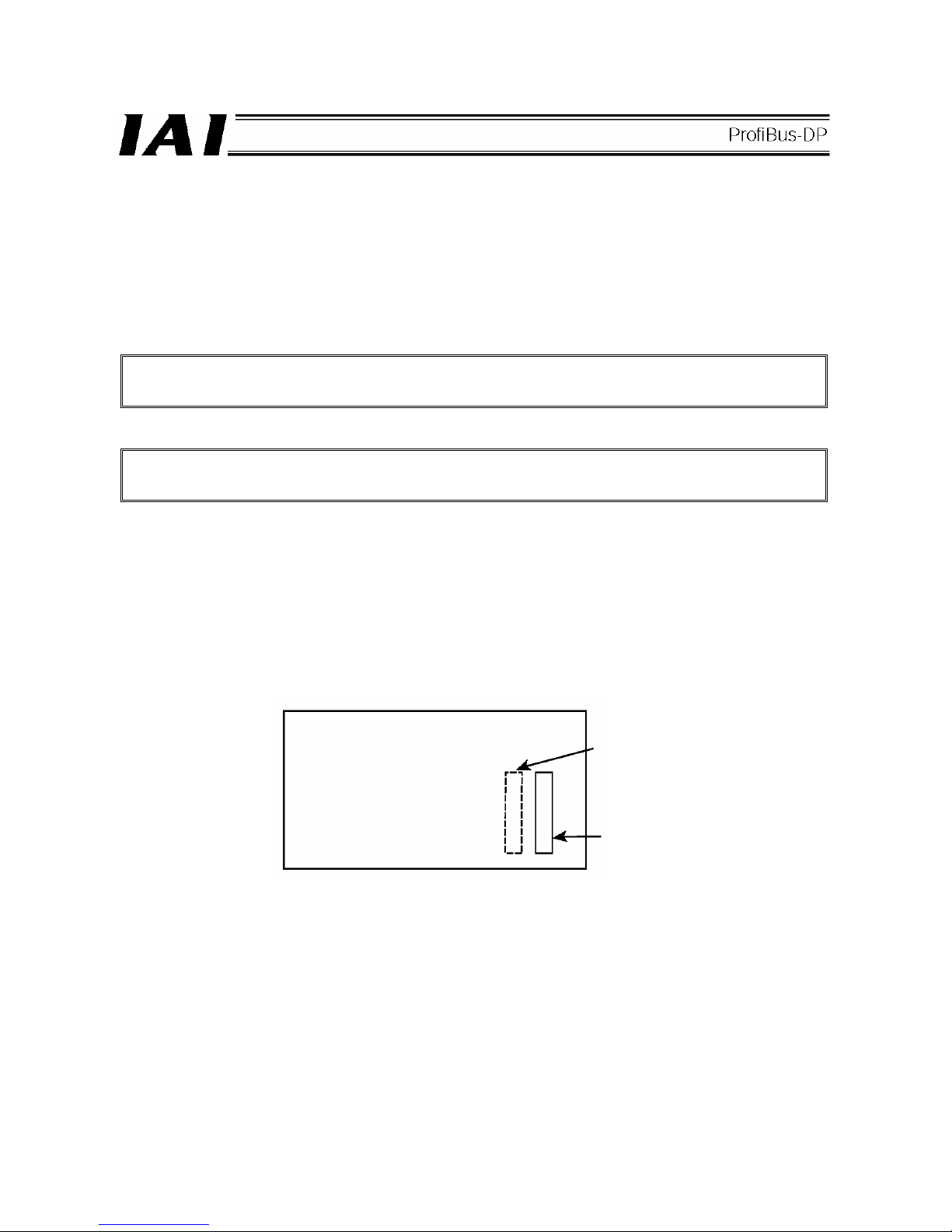
3.1 ProfiBus-DP Board Types and Installation Positions in the X-SEL
There are six types of X-SEL controllers that support ProfiBus-DP, as listed below. The installation position of the
ProfiBus-DP board is different depending on whether the X-SEL controller is of PR0 type or PR1 type.
* The PR1 board can be installed in any one of expansion I/O slots 1 to 3.
*2 The ProfiBus-DP board is installed in the same position as shown in Fig. 3.4. With a 5-axis or 6-axis
specification, the ProfiBus-DP board is installed in the same position as with a 4-axis specification.
Controller
type
J
K
K
P
Q
PX
QX
Network I/O
points
(maximum
inputs/outputs)
Board installation position
Standard
slot
(I/O1)
Expansion
slot 1
(I/O2)
Expansion
slot 2 or 3
(I/O3 or 4)
Not available
for 1-axis and
2-axis
specifications.
X-SEL model
I/O slot
arrangement
Fig. 3.1
Fig. 3.2
Fig. 3.3
Fig. 3.4
*2
*2
*2
*1
*1
Installation position of
field network board
Installation position of
field network board
Page 8

4
(1) Compact type (J type)
1-axis specification
*1
2-axis specification*1 3/4-axis specification
*2, *3
Fig. 3.1
*1) An I/O board cannot be installed in 1-axis and 2-axis specifications, because the ProfiBus-DP board
occupies the only slot available.
*2) With 3-axis and 4-axis specifications, only the “PR0” ProfiBus-DP board can be installed in the standard slot.
*3) With 3-axis and 4-axis specifications, one expansion I/O board can be installed in the expansion slot.
Expansion I/O board
Model [1] IA-103-X-32 (32 input points, 16 output points)
[2] IA-103-X-16 (16 input points, 32 output points)
ProfiBus-DP board ProfiBus-DP board Expansion slot ProfiBus-DP board
(Installed in the standard slot.)
Page 9

5
(2) General-purpose type (K type)
z Either a ProfiBus-DP board or standard I/O board must be always installed in the standard slot (I/O1 --- slot
at the far left).
z The “PR1” ProfiBus-DP board occupies two expansion slots. If this type of ProfiBus-DP board is selected,
only one expansion slot can be used.
z Either an expansion I/O board
*1
or SIO board*2 can be installed in an expansion slot.
Fig. 3.2
*1 Expansion I/O board
Mode [1] IA-103-X-32 (32 input points + 16 output points, NPN specification)
[2] IA-103-X-32-P (32 input points + 16 output points, PNP specification)
[3] IA-103-X-16 (16 input points + 32 output points, NPN specification)
[4] IA-103-X-16-P (16 input points + 32 output points, PNP specification)
[5] IA-IO-3204-NP (48 input points + 48 output points, NPN specification)
[6] IA-IO-3204-PN (48 input points + 48 output points, PNP specification)
[7] IA-IO-3205-NP (48 input points + 48 output points, NPN specification)
[8] IA-IO-3205-PN (48 input points + 48 output points, PNP specification)
(Note) [5] and [6] are used exclusively for the K, P and Q types, while [7] and [8] are used
exclusively for the J type.
For specification details, refer to “Operation Manual for X-SEL Controller.”
*2 SIO board
Mode [1] IA-105-X-MW-A (RS232C)
[2] IA-105-X-MW-B (RS422C)
[3] IA-105-X-MW-C (RS485C)
With all boards, one board can support two channels.
Expansion slots 1 to 3
ProfiBus-DP board
(Installed in the standard slot.)
Page 10

6
Fig. 3.3
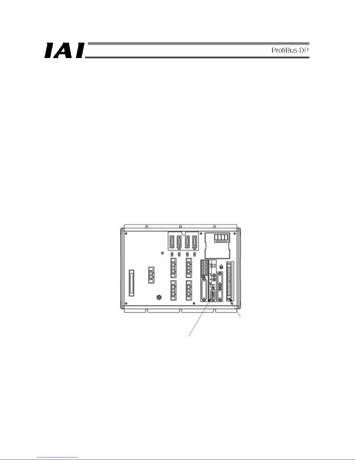
(3) P/Q types
z The ProfiBus-DP board is installed in the installation position of field network board.
Fig. 3.4
Expansion slots 2 and 3
ProfiBus-DP board
(Installed in expansion slot 1.)
Standard I/O board
Standard I/O
Standard I/O
ProfiBus-DP board
ProfiBus-DP board
Expansion I/O
Page 11

7
3.2 Setting a ProfiBus-DP Board (Slave Station)
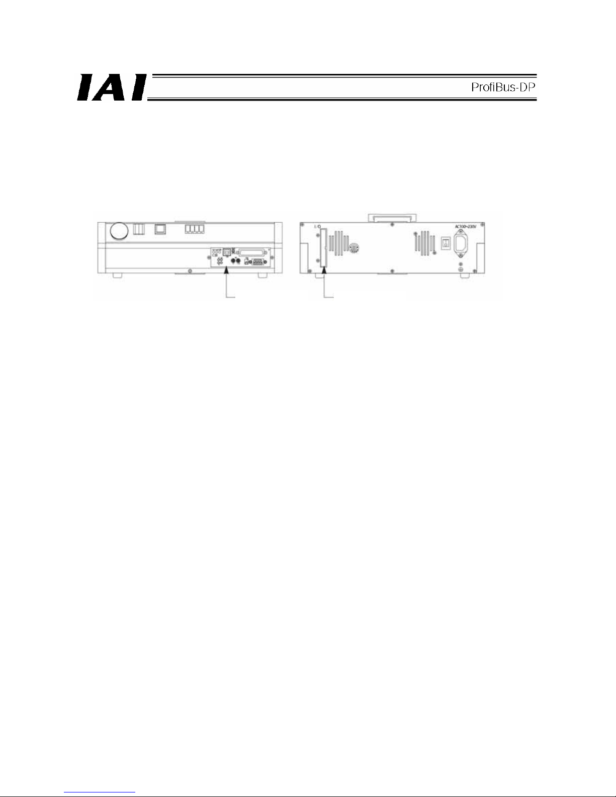
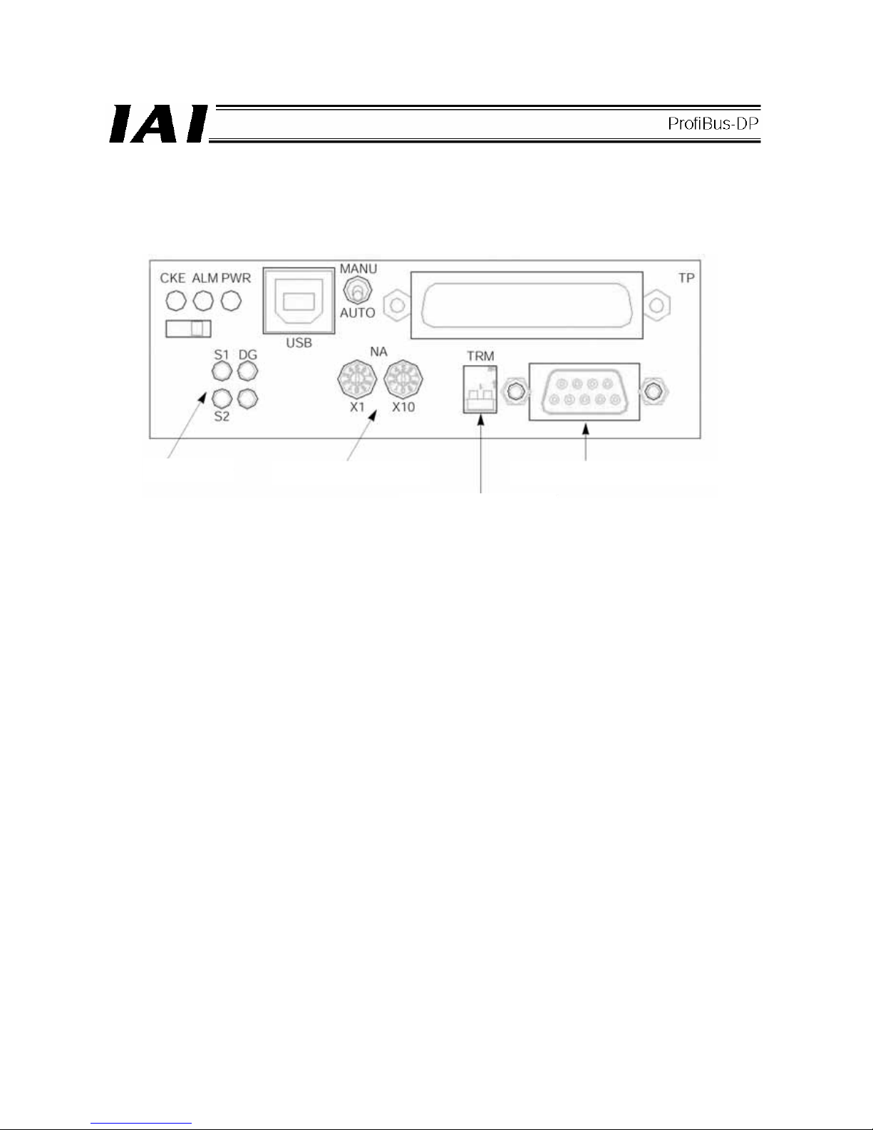
(1) Name of each part
J/K/JX/KX/ type P/Q/PX/QX type
ProfiBus-DP communication connector
Termination switch
Address setting dials
Monitor LEDs
ProfiBus-DP communication connector
Termination switch
Address setting dials
Monitor LEDs
Page 12

8
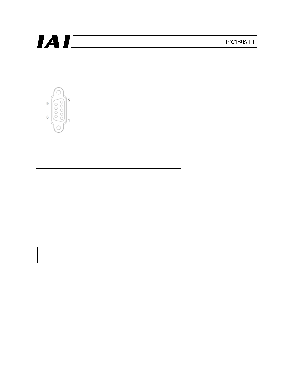
(2) ProfiBus-DP communication connector interface specifications
This is a 9-pin, female D-sub connector recommended by the ProfiBus-DP standard EN 50170.
Connector
Pin No. Description Contents
3 B-Line RxD x TxD (Positive signal line)
5 GND Shield
8 A-Line /RxD x /TxD (Negative signal line)
Housing GND Shield
* Pins 1, 2, 4, 6, 7 and 9 are not used (they need not be wired).
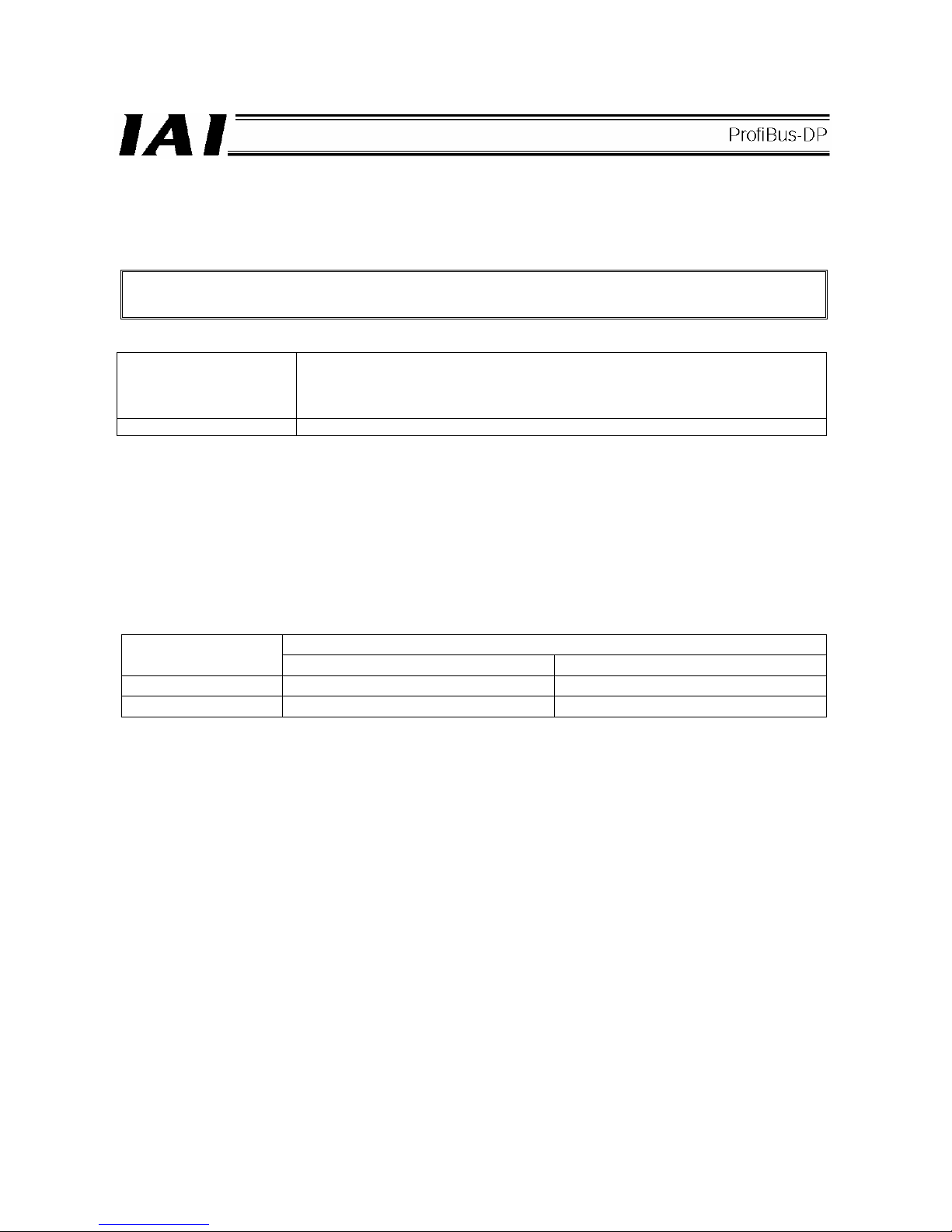
(3) Bus termination settings <Set using the termination switch>
Among the units connected to a ProfiBus-DP network, the devices at both ends require termination to prevent
reflected waves from entering the bus line again.
This ProfiBus-DP module provides a termination switch that makes this termination easy.
The user need not install a separate terminal resistor. Never install an additional terminal resistor, as it may
have negative impact on bus communication or cause a communication error, etc.
<Bus termination settings>
.
Termination switch ON Termination enabled
(If this switch is turned ON mistakenly when the module is connected in a position
other than the end of the network, bus communication may be negatively impacted
or a communication error, etc., may result.)
Termination switch OFF Termination disabled
Page 13

9
(4) Node address settings <Set by the address setting dials>
The address of each ProfiBus-DP slave station is set using the “x10” and “x1” rotary switches shown in the figure
under (1).
Set a desired address according to the following rule:
Node address number = (“Value set by x10” rotary switch x 10) + (“Value set by x1” rotary switch x1)
Example)
Example of rotary switch settings
Target station number
“X10” setting (x 10) “X1” setting (x 1)
9 0 9
12 1 2
Note 1) When setting ProfiBus-DP station numbers, remember that the ProfiBus-DP master station is always
assigned station number 0. Accordingly, numbers 1 to 99 are available for slave stations.
Note 2) The node address cannot be changed while the slave is communicating with the master.
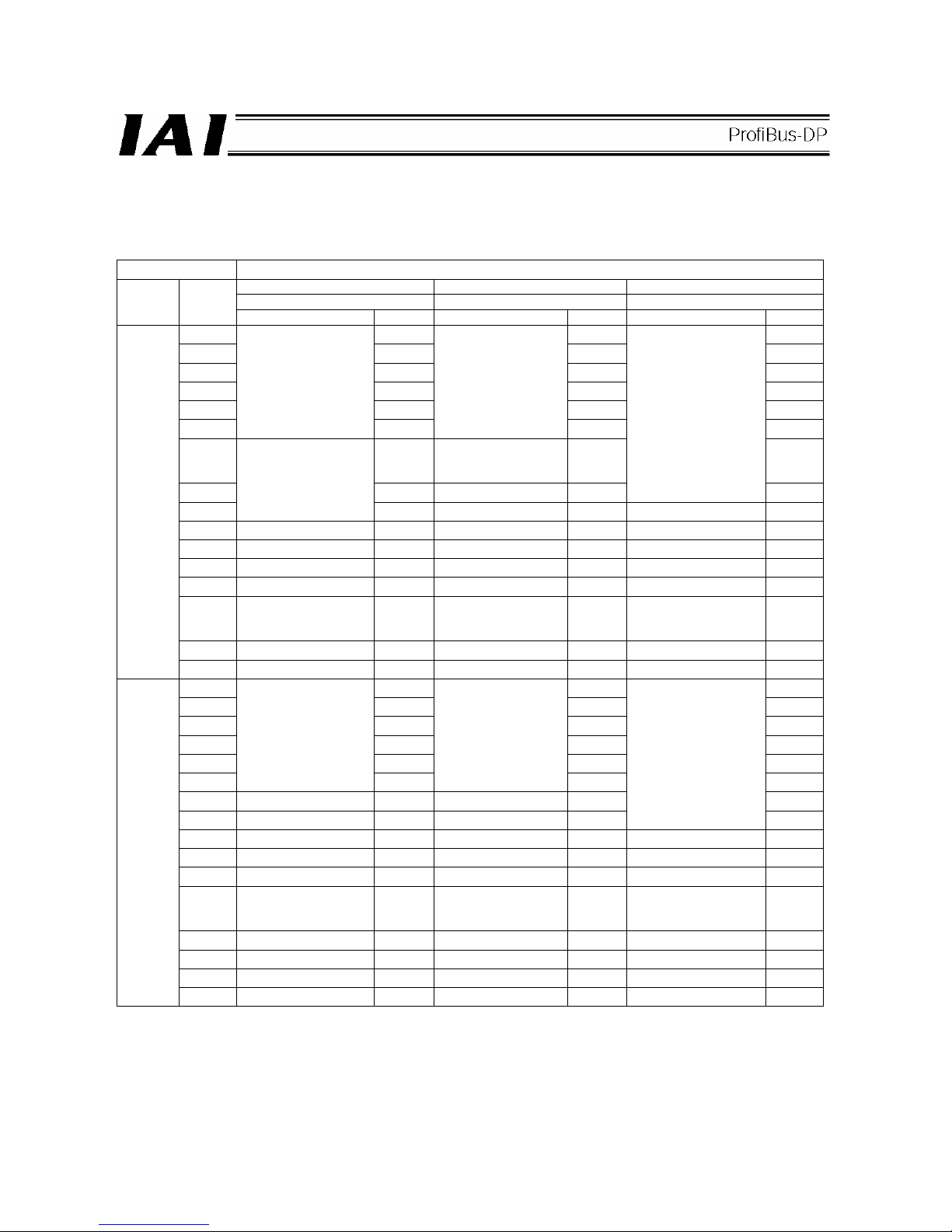
(5) Monitor LED indications
LED Color Status Definition Description (cause)
L1 -
Not used Not defined
L2
Online
Green Steady light Communicating
normally
• The module is operating normally (The module
is connected to the fieldbus and is therefore in
“online” state.)
L3
Offline
Red Steady light Offline
• The module is not connected to the fieldbus and
is therefore in “offline” state.
Unlit No error
-
Blinking at 1 Hz I/O size error
• This LED blinks when the specified I/O size is
invalid.
Blinking at 2 Hz Connection not
yet established
• A system setting error (internal error)
L4
Error status
Red
Blinking at 4 Hz Communication
hardware error
• This LED blinks when a communication
hardware error has been detected during the
initialization of the system.
Page 14
10
3.3 Setting X-SEL I/O Parameters (Assigning I/O Ports)
Set the X-SEL input/output ports to be used in ProfiBus-DP communication. The X-SEL supports many variations
of input/output port settings depending on how the applicable I/O parameters are set. (For details, refer to
“Operation Manual for X-SEL Controller.” All of the parameter numbers shown below indicate the I/O parameter
numbers of the X-SEL controller.)
3.3.1 Board Installation Positions (Slots) and I/O Parameters
I/O parameter Nos. 2 to 9
Enter the first I/O numbers among the I/Os assigned to the installed board.
Enter “-1” for port numbers not used.
Error monitor parameter Nos. 10 to 13
In normal conditions of use, set “1” for an expansion I/O board or SIO board.
For a ProfiBus-DP board, the setting is normally “2.”
Take note that the above setting can be changed in a range of “0” to “3” at the user’s responsibility.
If set to “0” --- The controller does not monitor any error occurring in the board installed in each slot.
If set to “1” --- The controller monitors all errors occurring in the board installed in each slot.
If set to “2” --- The controller monitors all errors occurring in the board installed in each slot, except for errors
relating to the 24-V board power supply.
If set to “3” --- The controller monitors only errors relating to the 24-V board power supply for the board installed
in each slot.
(1) J/JX type (compact type)
(Note) The J type has no expansion slots I/O2 and 3. With this type of controller, therefore, parameter Nos. 6 to
9 are all set to “-1,” while Nos. 12 and 13 are set to “0.”
If the controller is of 1-axis or 2-axis specification, Nos. 4 and 5 are also set to “-1,” while No. 11 is set to
“0.”
(3/4-axis specifications)
Parameter No. 4
No. 5
No. 11
Parameter No. 2
No. 3
No. 10
Page 15

11
(2) K/KX type
Note) One ProfiBus-DP board occupies two slots. Accordingly, Nos. 4 and 5 are set to “-1,” and No. 11 to “0,”
when a ProfiBus-DP board is set in the slots denoted by A above. If a ProfiBus-DP board is set in the
slots denoted by B, Nos. 8 and 9 are set to “-1,” while No. 13 is set to “0.”
(3) P/PX/Q/QX type
Parameter No. 2
No. 3
No. 10
Parameter No. 4
No. 5
No. 11
Parameter No. 6
No. 7
No. 12
Parameter No. 8
No. 9
No. 13
ProfiBus-DP
ProfiBus-DP
Standard I/O
Standard I/O
Parameter No.16
No.17
No.18
Parameter No.2
No.3
No.10
Parameter No.16
No.17
No.18
Parameter No.2
No.3
No.10
Parameter No.4
No.5
No.11
Parameter No.8
No.9
No.13
Parameter No.6
No.7
No.11
Page 16

12
3.3.2 Factory-set Parameters (Default Settings)
(1) Factory-set parameters for the J/K/JX/KX types
• I/O Parameter
Settings
No. Parameter name Input range
A B C
Remarks
1
Input/output port assignment type
0 ~ 20 0 0 0
0: Fixed assignment
1: Automatic assignment (Priority: Slot 1 ~)
* Ports are assigned automatically only
for the contiguous slots in use, starting
from slot 1 = For safety reasons.
2
Standard I/O fixed assignment:
Initial input port number (I/O1)
-1 ~ 599 000 000 -1
0 + (multiple of 8) (The parameter is invalid
if a negative value is set.)
3
Standard I/O fixed assignment:
Initial output port number (I/O1)
-1 ~ 599 300 300 -1
300 + (multiple of 8) (The parameter is
invalid if a negative value is set.)
4
Expansion I/O1 fixed assignment:
Initial input port number (I/O2) -1 ~ 599 -1 -1 -1
0 + (multiple of 8) (The parameter is invalid
if a negative value is set.)
(Slot next to standard I/O)
5
Expansion I/O1 fixed assignment:
Initial output port number (I/O2)
-1 ~ 599 -1 -1 -1
300 + (multiple of 8) (The parameter is
invalid if a negative value is set.)
6
Expansion I/O2 fixed assignment:
Initial input port number (I/O3)
-1 ~ 599 -1 -1 000
0 + (multiple of 8) (The parameter is invalid
if a negative value is set.)
7
Expansion I/O2 fixed assignment:
Initial output port number (I/O3)
-1 ~ 599 -1 -1 300
300 + (multiple of 8) (The parameter is
invalid if a negative value is set.)
8
Expansion I/O3 fixed assignment:
Initial input port number (I/O4)
-1 ~ 599 -1 -1 -1
0 + (multiple of 8) (The parameter is invalid
if a negative value is set.)
9
Expansion I/O3 fixed assignment:
Initial output port number (I/O4)
-1 ~ 599 -1 -1 -1
300 + (multiple of 8) (The parameter is
invalid if a negative value is set.)
10 Standard I/O error monitor 0 ~ 5 2 2 2 0: Not monitored
11 Expansion I/O1 error monitor 0 ~ 5 0 0 0 1: Monitored
12
Expansion I/O2 error monitor
0 ~ 5 0 0 2
2: Monitored (24-V I/O power errors are
not monitored)
(Main application version 0.55 or later)
13
Expansion I/O3 error monitor
0 ~ 5 0 0 0
3: Monitored (only 24-V I/O power errors
are not monitored).
(Main application version 0.55 or later)
14
Network I/F card remote input
ports used
0 ~ 256 64 64 64
Multiple of 8
15
Network I/F card remote output
ports used
0 ~ 256 64 64 64
Multiple of 8
Page 17

13
(2) Factory-set parameters for the P/PX/Q/QX types
No. Parameter name Input range Settings Remarks
1
Input/output port assignment type
0 ~ 20 0
0: Fixed assignment
1: Automatic assignment (Priorities:
Network I/F module → Slot 1 (standard
I/O) ~)
* Ports are assigned automatically only
for the contiguous slots in use, starting
from slot 1 = For safety reasons.
2
Standard I/O fixed assignment:
Initial input port number (I/O1)
-1 ~ 599 -1
0 + (multiple of 8) (The parameter is
invalid if a negative value is set.)
3
Standard I/O fixed assignment:
Initial output port number (I/O1)
-1 ~ 599 -1
300 + (multiple of 8) (The parameter is
invalid if a negative value is set.)
4
Expansion I/O1 fixed assignment:
Initial input port number (I/O2) -1 ~ 599 -1
0 + (multiple of 8) (The parameter is
invalid if a negative value is set.)
(Slot next to standard I/O)
5
Expansion I/O1 fixed assignment:
Initial output port number (I/O2)
-1 ~ 599 -1
300 + (multiple of 8) (The parameter is
invalid if a negative value is set.)
6
Expansion I/O2 fixed assignment:
Initial input port number (I/O3)
-1 ~ 599 -1
0 + (multiple of 8) (The parameter is
invalid if a negative value is set.)
7
Expansion I/O2 fixed assignment:
Initial output port number (I/O3)
-1 ~ 599 -1
300 + (multiple of 8) (The parameter is
invalid if a negative value is set.)
8
Expansion I/O3 fixed assignment:
Initial input port number (I/O4)
-1 ~ 599 -1
0 + (multiple of 8) (The parameter is
invalid if a negative value is set.)
9
Expansion I/O3 fixed assignment:
Initial output port number (I/O4)
-1 ~ 599 -1
300 + (multiple of 8) (The parameter is
invalid if a negative value is set.)
10 Standard I/O error monitor 0 ~ 5 0 0: Not monitored
11 Expansion I/O1 error monitor 0 ~ 5 0 1: Monitored
12
Expansion I/O2 error monitor
0 ~ 5 0
2: Monitored (24-V I/O power errors are
not monitored)
13
Expansion I/O3 error monitor
0 ~ 5 0
3: Monitored (only 24-V I/O power errors
are not monitored).
14
Network I/F card remote input
ports used
0 ~ 256 64
Multiple of 8
15
Network I/F card remote output
ports used
0 ~ 256 64
Multiple of 8
16
Network I/F module fixed
assignment: Initial input port
number
-1 ~ 599 0
0 + (multiple of 8) (The parameter is
invalid if a negative value is set.)
17
Network I/F module fixed
assignment: Initial input port
number
-1 ~ 599 300
300 + (multiple of 8) (The parameter is
invalid if a negative value is set.)
18
Network I/F module: Error monitor
0 ~ 5 1
0: Not monitored
1: Monitored
* Some exceptions apply.
(I/O1) to (I/O4) indicate slot numbers.
Page 18

14
3.3.3 Automatically Assigning X-SEL I/Os
Set the X-SEL input/output ports to be used in ProfiBus-DP communication. The X-SEL supports many
variations of input/output port settings depending on how the applicable I/O parameters are set. (For details,
refer to “Operation Manual for X-SEL Controller.”)
This manual covers the representative setting method as explained below.
Basically, the input/output port assignment type is set to “automatic assignment” using I/O parameter No. 1, and
input/output port addresses are set using Nos. 2 and 3. If an expansion I/O board is used, install the expansion
I/O board in each slot number in the specified order, and I/O ports will be assigned automatically. There is no
need to set the parameters for initial input/output port numbers for the expansion I/O board.
I/O parameter number Value Description
1 1 I/O numbers are assigned automatically.
2 0 Standard DIs are assigned from input port 0.
3 300 Standard DOs are assigned from output port 300.
14 n
The number of ProfiBus-DP input points is specified as a multiple of 16.
(16 ≤ n ≤ 256)
15 m
The number of ProfiBus-DP output points is specified as a multiple of 16.
(16 ≤ m ≤ 256)
3.3.4 Setting Examples for J/JX/K/KX Type Controllers
(1) Setting example when only a ProfiBus-DP board is installed in the standard I/O slot (automatic assignment)
(A ProfiBus-DP board is installed in the standard I/O slot and all expansion I/O slots are empty)
Example: In the case of automatic assignment, the following settings apply if you want to use 128 input points
and 128 output points as I/O ports of the ProfiBus-DP slave station:
[1] Enter “1” in I/O parameter No. 1 to specify automatic assignment.
[2] Set I/O parameter No. 10, “Standard I/O error monitor” to “2.”
[3] Settings are complete by only specifying I/O parameter Nos. 14 and 15, “Input/output ports used.”
X-SEL (J type, 3/4-axis specification)
Not used
(Not available for 1/2-axis specifications.)
Input port Nos. 000 to 015
Output port Nos. 300 to 315
Page 19

15
X-SEL (K type)
No. Parameter name Input range Settings Remarks
1
Input/output port assignment type
0 ~ 20 1
0: Fixed assignment
1: Automatic assignment (Priority: Slot 1 ~)
* Ports are assigned automatically only for the
contiguous slots in use, starting from slot 1 =
For safety reasons.
2
Standard I/O fixed assignment: Initial
input port number (I/O1)
-1 ~ 599 000
0 + (multiple of 8) (The parameter is invalid if a
negative value is set.)
3
Standard I/O fixed assignment: Initial
output port number (I/O1)
-1 ~ 599 300
300 + (multiple of 8) (The parameter is invalid if a
negative value is set.)
4
Expansion I/O1 fixed assignment:
Initial input port number (I/O2) -1 ~ 599 -1
0 + (multiple of 8) (The parameter is invalid if a
negative value is set.)
(Slot next to standard I/O)
5
Expansion I/O1 fixed assignment:
Initial output port number (I/O2)
-1 ~ 599 -1
300 + (multiple of 8) (The parameter is invalid if a
negative value is set.)
6
Expansion I/O2 fixed assignment:
Initial input port number (I/O3)
-1 ~ 599 -1
0 + (multiple of 8) (The parameter is invalid if a
negative value is set.)
7
Expansion I/O2 fixed assignment:
Initial output port number (I/O3)
-1 ~ 599 -1
300 + (multiple of 8) (The parameter is invalid if a
negative value is set.)
8
Expansion I/O3 fixed assignment:
Initial input port number (I/O4)
-1 ~ 599 -1
0 + (multiple of 8) (The parameter is invalid if a
negative value is set.)
9
Expansion I/O3 fixed assignment:
Initial output port number (I/O4)
-1 ~ 599 -1
300 + (multiple of 8) (The parameter is invalid if a
negative value is set.)
10 Standard I/O error monitor 0 ~ 5 2 0: Not monitored
11 Expansion I/O1 error monitor 0 ~ 5 0 1: Monitored
12
Expansion I/O2 error monitor
0 ~ 5 0
2: Monitored (only 24-V I/O power errors are
not monitored)
(Main application version 0.55 or later)
13
Expansion I/O3 error monitor
0 ~ 5 0
3: Monitored (only 24-V I/O power errors are
not monitored).
(Main application version 0.55 or later)
14
Network I/F card remote input ports
used
0 ~ 256 128
Multiple of 16
15
Network I/F card remote output ports
used
0 ~ 256 128
Multiple of 16
Not used
Input port Nos. 000 to 015
Output port Nos. 300 to 315
Page 20

16
(2) Setting example when a ProfiBus-DP board is used with an expansion I/O board (automatic
assignment)
The port numbers of the expansion board are assigned automatically in accordance with the numbers of I/O ports
of the ProfiBus-DP slave station set by I/O parameter Nos. 14 and 15.
Example: If one expansion I/O board (IA-103-X-32: 32 input points, 16 output points) is installed in expansion
slot I/O1 when the maximum numbers of inputs and outputs of the ProfiBus-DP slave station are 256
and 256, respectively, entering “256” in I/O parameter Nos. 14 and 15 will automatically set I/O
parameter Nos. 2 and 3, as shown below.
A ProfiBus-DP board is installed in the standard I/O slot and an expansion I/O board is installed in expansion slot
I/O1.
[1] Enter “1” in I/O parameter No. 1 to specify automatic assignment. (Default setting)
[2] Set I/O parameter No. 10, “Standard I/O error monitor” to “2.” (Default setting)
[3] Set I/O parameter No. 11, “Standard I/O error monitor” to a value in a range of “1” to “3.”
[4] Set I/O parameter Nos. 14 and 15, “Input/output ports used.” <A desired value can be set in a range of 8 to
256 (but the value must be a multiple of 8)>.
As a standard, input port numbers are assigned sequentially from No. 0. Since the ProfiBus-DP slave station
already occupies 0 to 255 (total 256 points), “256” is automatically assigned as the initial input port number for
expansion slot I/O1 based on fixed assignment.
On the other hand, output port numbers are assigned sequentially from No. 300 as a standard. Since the
ProfiBus-DP slave station already occupies 300 to 555 (total 256 points), “556” is automatically assigned as the
initial output port number expansion slot I/O1 based on fixed assignment.
X-SEL (J type, 3/4-axis specification)
X-SEL (K type)
Input port Nos. 256 to 287
Output port Nos. 556 to 571
Input port Nos. 000 to 255
Output port Nos. 300 to 555
Input port Nos. 256 to 287
Output port Nos. 556 to 571
Input port Nos. 000 to 255
Output port Nos. 300 to 555
Page 21

17
No. Parameter name Input range Settings Remarks
1
Input/output port assignment type
0 ~ 20 1
0: Fixed assignment
1: Automatic assignment (Priority: Slot 1 ~)
* Ports are assigned automatically only for the
contiguous slots in use, starting from slot 1 =
For safety reasons.
2
Standard I/O fixed assignment:
Initial input port number (I/O1)
-1 ~ 599 000
0 + (multiple of 8) (The parameter is invalid if a
negative value is set.)
3
Standard I/O fixed assignment:
Initial output port number (I/O1)
-1 ~ 599 300
300 + (multiple of 8) (The parameter is invalid if
a negative value is set.)
4
Expansion I/O1 fixed assignment:
Initial input port number (I/O2)
-1 ~ 599 256
0 + (multiple of 8) (The parameter is invalid if a
negative value is set.)
(Slot next to standard I/O)
5
Expansion I/O1 fixed assignment:
Initial output port number (I/O2)
-1 ~ 599 556
300 + (multiple of 8) (The parameter is invalid if
a negative value is set.)
6
Expansion I/O2 fixed assignment:
Initial input port number (I/O3)
-1 ~ 599 -1
0 + (multiple of 8) (The parameter is invalid if a
negative value is set.)
7
Expansion I/O2 fixed assignment:
Initial output port number (I/O3)
-1 ~ 599 -1
300 + (multiple of 8) (The parameter is invalid if
a negative value is set.)
8
Expansion I/O3 fixed assignment:
Initial input port number (I/O4)
-1 ~ 599 -1
0 + (multiple of 8) (The parameter is invalid if a
negative value is set.)
9
Expansion I/O3 fixed assignment:
Initial output port number (I/O4)
-1 ~ 599 -1
300 + (multiple of 8) (The parameter is invalid if
a negative value is set.)
10 Standard I/O error monitor 0 ~ 5 2 0: Not monitored
11 Expansion I/O1 error monitor 0 ~ 5 1 1: Monitored
12
Expansion I/O2 error monitor
0 ~ 5 0
2: Monitored (only 24-V I/O power errors are
not monitored)
13
Expansion I/O3 error monitor
0 ~ 5 0
3: Monitored (only 24-V I/O power errors are
not monitored).
(Main application version 0.55 or later)
14
Network I/F card remote input
ports used
0 ~ 256 256
Multiple of 16
15
Network I/F card remote output
ports used
0 ~ 256 256
Multiple of 16
Page 22

18
(3) Setting example when a ProfiBus-DP board is used with an expansion I/O board (fixed
assignment)
Under fixed assignment (where I/O parameter No. 1 is set to “0”), you can set desired initial I/O port
numbers.
Under automatic assignment the initial I/O port numbers (input number 0 ~ / output number 300 ~) can only
be set after the standard I/Os have been assigned. Under fixed assignment, on the other hand, the initial I/O
port numbers (input number 0 ~ / output number 300 ~) can be set freely for other boards installed in
expansion slots I/O1 to 3.
Example: One expansion I/O board (IA-103-X-32: 32 input points, 16 output points) is installed in expansion slot
I/O1 when the numbers of inputs and outputs of the ProfiBus-DP slave station are 256 and 256,
respectively. If the assignments as shown below are performed, the expansion I/O board is assigned
for the initial I/O port numbers (input number 0 ~ / output number 300 ~), and the ProfiBus-DP slave
station installed in the standard I/O slot is assigned for the subsequent numbers.
[1] Enter “1” in I/O parameter No. 1 to specify fixed assignment.
[2] Set I/O parameter No. 4, “Expansion I/O 1 fixed assignment: Initial input port number” to “0.”
[3] Set I/O parameter No. 5, “Expansion I/O 1 fixed assignment: Initial output port number” to “300.”
[4] Since the expansion I/O board IA-103-X-32 has 32 input point sand 16 output points, the last expansion input
port number becomes 31, while the last expansion output port number becomes 15.
[5] Set I/O parameter No. 2, “Standard I/O 1 fixed assignment: Initial input port number” to “32.”
[6] Set I/O parameter No. 3, “Standard I/O 1 fixed assignment: Initial output port number” to “16.”
[7] Set I/O parameter No. 10, “Standard I/O error monitor” to “2.”
[8] Set I/O parameter No. 11, “Standard I/O error monitor” to a value in a range of “1” to “3.”
[9] Since the maximum numbers of input and output points of the ProfiBus-DP slave station are 256 and 256,
respectively, enter “256” in I/O parameter Nos. 14 and 15, “Input/output ports used.”
The settings are complete.
X-SEL (K type)
Input port Nos. 000 to 031
Output port Nos. 300 to 315
Input port Nos. 032 to 287
Output port Nos. 316 to 571
Page 23

19
No. Parameter name Input range Settings Remarks
1
Input/output port assignment type
0 ~ 20 1
0: Fixed assignment
1: Automatic assignment (Priority: Slot 1 ~)
* Ports are assigned automatically only for the
contiguous slots in use, starting from slot 1 =
For safety reasons.
2
Standard I/O fixed assignment:
Initial input port number (I/O1)
-1 ~ 599 032
0 + (multiple of 8) (The parameter is invalid if a
negative value is set.)
3
Standard I/O fixed assignment:
Initial output port number (I/O1)
-1 ~ 599 316
300 + (multiple of 8) (The parameter is invalid if
a negative value is set.)
4
Expansion I/O1 fixed assignment:
Initial input port number (I/O2)
-1 ~ 599 000
0 + (multiple of 8) (The parameter is invalid if a
negative value is set.)
(Slot next to standard I/O)
5
Expansion I/O1 fixed assignment:
Initial output port number (I/O2)
-1 ~ 599 300
300 + (multiple of 8) (The parameter is invalid if
a negative value is set.)
6
Expansion I/O2 fixed assignment:
Initial input port number (I/O3)
-1 ~ 599 -1
0 + (multiple of 8) (The parameter is invalid if a
negative value is set.)
7
Expansion I/O2 fixed assignment:
Initial output port number (I/O3)
-1 ~ 599 -1
300 + (multiple of 8) (The parameter is invalid if
a negative value is set.)
8
Expansion I/O3 fixed assignment:
Initial input port number (I/O4)
-1 ~ 599 -1
0 + (multiple of 8) (The parameter is invalid if a
negative value is set.)
9
Expansion I/O3 fixed assignment:
Initial output port number (I/O4)
-1 ~ 599 -1
300 + (multiple of 8) (The parameter is invalid if
a negative value is set.)
10 Standard I/O error monitor 0 ~ 5 1 0: Not monitored
11 Expansion I/O1 error monitor 0 ~ 5 2 1: Monitored
12
Expansion I/O2 error monitor
0 ~ 5 0
2: Monitored (only 24-V I/O power errors are
not monitored)
13
Expansion I/O3 error monitor
0 ~ 5 0
3: Monitored (only 24-V I/O power errors are
not monitored).
(Main application version 0.55 or later)
14
Network I/F card remote input
ports used
0 ~ 256 256
Multiple of 16
15
Network I/F card remote output
ports used
0 ~ 256 256
Multiple of 16
Page 24

20
3.3.5 Setting Examples for P/PX/Q/QX Type Controllers
(1) Setting example when only a ProfiBus-DP board is used (automatic assignment)
Example: The following settings apply when the I/O ports of the ProfiBus-DP board are used by 32 input points
and 16 output points, each from the beginning, by leaving other I/O ports unused, just like when a
standard X-SEL I/O board (50-pin connector) is used.
[1] Enter “1” in I/O parameter No. 1 to specify automatic assignment. (Default setting)
[2] Set I/O parameter No. 10, “Standard I/O error monitor” to “2.” (Default setting)
[3] Set I/O parameter Nos. 14 and 15, “Input/output ports used,” and the settings are complete. <A desired value
can be set in a range of 0 to 256 (but the value must be a multiple of 16)>.
Input port Nos. 000 to 015
Output port Nos. 300 to 315
Not used
Page 25

21
I/O Parameters of X-SEL P/PX/Q/QX Type Controllers
No. Parameter name
Default
(reference)
Input
range
Setting
Remarks
1
Input/output port assignment type
0 0 ~ 20 1
0: Fixed assignment
1: Automatic assignment (Priorities:
Network I/F module → Slot 1
(standard I/O) ~)
* Ports are assigned automatically only
for the contiguous slots in use, starting
from slot 1 = For safety reasons.
2
Standard I/O fixed assignment:
Initial input port number (I/O1)
-1 -1 ~ 599 -1
0 + (multiple of 8) (The parameter is
invalid if a negative value is set.)
3
Standard I/O fixed assignment:
Initial output port number (I/O1)
-1 -1 ~ 599 -1
300 + (multiple of 8) (The parameter is
invalid if a negative value is set.)
4
Expansion I/O1 fixed assignment:
Initial input port number (I/O2) -1 -1 ~ 599 -1
0 + (multiple of 8) (The parameter is
invalid if a negative value is set.)
(Slot next to standard I/O)
5
Expansion I/O1 fixed assignment:
Initial output port number (I/O2)
-1 -1 ~ 599 -1
300 + (multiple of 8) (The parameter is
invalid if a negative value is set.)
6
Expansion I/O2 fixed assignment:
Initial input port number (I/O3)
-1 -1 ~ 599 -1
0 + (multiple of 8) (The parameter is
invalid if a negative value is set.)
7
Expansion I/O2 fixed assignment:
Initial output port number (I/O3)
-1 -1 ~ 599 -1
300 + (multiple of 8) (The parameter is
invalid if a negative value is set.)
8
Expansion I/O3 fixed assignment:
Initial input port number (I/O4)
-1 -1 ~ 599 -1
0 + (multiple of 8) (The parameter is
invalid if a negative value is set.)
9
Expansion I/O3 fixed assignment:
Initial output port number (I/O4)
-1 -1 ~ 599 -1
300 + (multiple of 8) (The parameter is
invalid if a negative value is set.)
10 Standard I/O error monitor 0 0 ~ 5 0 0: Not monitored
11 Expansion I/O1 error monitor 0 0 ~ 5 0 1: Monitored
12
Expansion I/O2 error monitor
0 0 ~ 5 0
2: Monitored (24-V I/O power errors
are not monitored)
13
Expansion I/O3 error monitor
0 0 ~ 5 0
3: Monitored (only 24-V I/O power
errors are not monitored).
14
Network I/F card remote input
ports used
64 0 ~ 256 32
Multiple of 8
15
Network I/F card remote output
ports used
64 0 ~ 256 16
Multiple of 8
16
Network I/F module fixed
assignment: Initial input port
number
0 -1 ~ 599 0
0 + (multiple of 8) (The parameter is
invalid if a negative value is set.)
17
Network I/F module fixed
assignment: Initial input port
number
300 -1 ~ 599 300
300 + (multiple of 8) (The parameter is
invalid if a negative value is set.)
18
Network I/F module: Error monitor
1 0 ~ 5 1
0: Not monitored
1: Monitored
* Some exceptions apply.
(I/O1) to (I/O4) indicate slot numbers.
Page 26

22
(2) Setting example when a ProfiBus-DP board is used with a standard I/O board (automatic
assignment)
Example: These settings are used when 256 input points and 256 output points are assigned, both from the
initial standard I/O ports, to the ProfiBus-DP board, and the remaining I/O port numbers are assigned
to the standard I/O board.
[1] Enter “1” in I/O parameter No. 1 to specify automatic assignment.
[2] Set I/O parameter No. 10, “Standard I/O error monitor” to “2.”
[3] Set I/O parameter No. 11, “Standard I/O error monitor” to “1,” “2” or “3.”
[4] Set I/O parameter Nos. 14 and 15, “Input/output ports used,” and the settings are complete. <A desired value
can be set in a range of 0 to 256 (but the value must be a multiple of 8)>.
Port numbers are automatically assigned to the expansion I/O board according to the numbers of I/O ports of
the ProfiBus-DP slave station that have been set by I/O parameter Nos. 14 and 15.
Input port Nos. 000 to 255
Output port Nos. 300 to 555
Input port Nos. 256 to 287
Output port Nos. 556 to 571
Page 27

23
I/O Parameters of X-SEL P/PX/Q/QX Type Controllers
No. Parameter name
Default
(reference)
Input
range
Setting
Remarks
1
Input/output port assignment type
0 0 ~ 20 1
0: Fixed assignment
1: Automatic assignment (Priorities:
Network I/F module → Slot 1
(standard I/O) ~)
* Ports are assigned automatically only
for the contiguous slots in use, starting
from slot 1 = For safety reasons.
2
Standard I/O fixed assignment:
Initial input port number (I/O1)
-1 -1 ~ 599 256
0 + (multiple of 8) (The parameter is
invalid if a negative value is set.)
3
Standard I/O fixed assignment:
Initial output port number (I/O1)
-1 -1 ~ 599 556
300 + (multiple of 8) (The parameter is
invalid if a negative value is set.)
4
Expansion I/O1 fixed assignment:
Initial input port number (I/O2) -1 -1 ~ 599 -1
0 + (multiple of 8) (The parameter is
invalid if a negative value is set.)
(Slot next to standard I/O)
5
Expansion I/O1 fixed assignment:
Initial output port number (I/O2)
-1 -1 ~ 599 -1
300 + (multiple of 8) (The parameter is
invalid if a negative value is set.)
6
Expansion I/O2 fixed assignment:
Initial input port number (I/O3)
-1 -1 ~ 599 -1
0 + (multiple of 8) (The parameter is
invalid if a negative value is set.)
7
Expansion I/O2 fixed assignment:
Initial output port number (I/O3)
-1 -1 ~ 599 -1
300 + (multiple of 8) (The parameter is
invalid if a negative value is set.)
8
Expansion I/O3 fixed assignment:
Initial input port number (I/O4)
-1 -1 ~ 599 -1
0 + (multiple of 8) (The parameter is
invalid if a negative value is set.)
9
Expansion I/O3 fixed assignment:
Initial output port number (I/O4)
-1 -1 ~ 599 -1
300 + (multiple of 8) (The parameter is
invalid if a negative value is set.)
10 Standard I/O error monitor 0 0 ~ 5 1 0: Not monitored
11 Expansion I/O1 error monitor 0 0 ~ 5 0 1: Monitored
12
Expansion I/O2 error monitor
0 0 ~ 5 0
2: Monitored (24-V I/O power errors
are not monitored)
13
Expansion I/O3 error monitor
0 0 ~ 5 0
3: Monitored (only 24-V I/O power
errors are not monitored).
14
Network I/F card remote input
ports used
64 0 ~ 256 256
Multiple of 16
15
Network I/F card remote output
ports used
64 0 ~ 256 256
Multiple of 16
16
Network I/F module fixed
assignment: Initial input port
number
0 -1 ~ 599 0
0 + (multiple of 8) (The parameter is
invalid if a negative value is set.)
17
Network I/F module fixed
assignment: Initial input port
number
300 -1 ~ 599 300
300 + (multiple of 8) (The parameter is
invalid if a negative value is set.)
18
Network I/F module: Error monitor
1 0 ~ 5 1
0: Not monitored
1: Monitored
* Some exceptions apply.
(I/O1) to (I/O4) indicate slot numbers.
Page 28
24
(3) Setting example when a ProfiBus-DP board is used with a standard I/O board (fixed assignment)
In automatic assignment, the initial I/O port numbers (No. 0 or greater for input / No. 300 or greater for
output) must be set on the standard I/O board. By using fixed assignment, however, you can set the initial I/O
port numbers on expansion I/O board 1 to 3 (No. 0 or greater for input / No. 300 or greater for output), other
than the standard I/O board.
Example: Assume the ProfiBus-DP slave station has 256 input points and 256 output points and an expansion
I/O board (IA-103-X-32: 32 input points, 16 output points) is installed in the expansion I/O1 slot. If you
want to assign the ports as follows, then assign the initial I/O port numbers (No. 0 or greater for input /
No. 300 or greater for output) to the expansion I/O board, and then assign the remaining port numbers
to the ProfiBus-DP slave station installed in the standard I/O slot.
[1] Enter “1” in I/O parameter No. 1 to specify fixed assignment.
[2] Set I/O parameter No. 4, “Expansion I/O1 fixed assignment: Initial input port number” to “0.”
[3] Set I/O parameter No. 5, “Expansion I/O1 fixed assignment: Initial output port number” to “300.”
[4] Since the expansion I/O board IA-103-X-32 has 32 input points and 16 output points, the last I/O port
numbers on the expansion I/O board are 31 for input and 15 for output.
[5] Set I/O parameter No. 2, “Standard I/O fixed assignment: Initial input port number” to “32.”
[6] Set I/O parameter No. 3, “Standard I/O fixed assignment: Initial output port number” to “16.”
[7] Set I/O parameter No. 10, “Standard I/O error monitor” to “2.”
[8] Set I/O parameter No. 11, “Standard I/O error monitor” to “1,” “2” or “3.”
[9] Since the maximum values of 256 and 256 are used for inputs and outputs of the ProfiBus-DP slave station,
enter “256” in both I/O parameter Nos. 14 and 15, “Input/output ports used.” The settings are complete.
Input port Nos. 032 to 287
Output port Nos. 316 to 571
Input port Nos. 000 to 031
Output port Nos. 300 to 315
Page 29

25
I/O Parameters of X-SEL P/PX/Q/QX Type Controllers
No. Parameter name
Default
(reference)
Input
range
Setting
Remarks
1
Input/output port assignment type
0 0 ~ 20 1
0: Fixed assignment
1: Automatic assignment (Priorities:
Network I/F module → Slot 1
(standard I/O) ~)
* Ports are assigned automatically only
for the contiguous slots in use, starting
from slot 1 = For safety reasons.
2
Standard I/O fixed assignment:
Initial input port number (I/O1)
-1 -1 ~ 599 000
0 + (multiple of 8) (The parameter is
invalid if a negative value is set.)
3
Standard I/O fixed assignment:
Initial output port number (I/O1)
-1 -1 ~ 599 300
300 + (multiple of 8) (The parameter is
invalid if a negative value is set.)
4
Expansion I/O1 fixed assignment:
Initial input port number (I/O2) -1 -1 ~ 599 -1
0 + (multiple of 8) (The parameter is
invalid if a negative value is set.)
(Slot next to standard I/O)
5
Expansion I/O1 fixed assignment:
Initial output port number (I/O2)
-1 -1 ~ 599 -1
300 + (multiple of 8) (The parameter is
invalid if a negative value is set.)
6
Expansion I/O2 fixed assignment:
Initial input port number (I/O3)
-1 -1 ~ 599 -1
0 + (multiple of 8) (The parameter is
invalid if a negative value is set.)
7
Expansion I/O2 fixed assignment:
Initial output port number (I/O3)
-1 -1 ~ 599 -1
300 + (multiple of 8) (The parameter is
invalid if a negative value is set.)
8
Expansion I/O3 fixed assignment:
Initial input port number (I/O4)
-1 -1 ~ 599 -1
0 + (multiple of 8) (The parameter is
invalid if a negative value is set.)
9
Expansion I/O3 fixed assignment:
Initial output port number (I/O4)
-1 -1 ~ 599 -1
300 + (multiple of 8) (The parameter is
invalid if a negative value is set.)
10 Standard I/O error monitor 0 0 ~ 5 1 0: Not monitored
11 Expansion I/O1 error monitor 0 0 ~ 5 0 1: Monitored
12
Expansion I/O2 error monitor
0 0 ~ 5 0
2: Monitored (24-V I/O power errors
are not monitored)
13
Expansion I/O3 error monitor
0 0 ~ 5 0
3: Monitored (only 24-V I/O power
errors are not monitored).
14
Network I/F card remote input
ports used
64 0 ~ 256 256
Multiple of 8
15
Network I/F card remote output
ports used
64 0 ~ 256 256
Multiple of 8
16
Network I/F module fixed
assignment: Initial input port
number
0 -1 ~ 599 032
0 + (multiple of 8) (The parameter is
invalid if a negative value is set.)
17
Network I/F module fixed
assignment: Initial input port
number
300 -1 ~ 599 316
300 + (multiple of 8) (The parameter is
invalid if a negative value is set.)
18
Network I/F module: Error monitor
1 0 ~ 5 1
0: Not monitored
1: Monitored
* Some exceptions apply.
(I/O1) to (I/O4) indicate slot numbers.
Page 30

26
3.3.6 X-SEL I/O Port Numbers
The standard I/O port numbers of the X-SEL are listed below.
The port numbers and function assignments of the X-SEL can be changed using I/O parameters.
(For details, refer to “Operation Manual for X-SEL Controller.”)
Port No. Function Port No. Function
000 Program start 300 Alarm output
001 General-purpose input 301 Ready output
002 General-purpose input 302 Emergency stop output
003 General-purpose input 303 General-purpose output
004 General-purpose input 304 General-purpose output
005 General-purpose input 305 General-purpose output
006 General-purpose input 306 General-purpose output
007 Program specification (PRG No. 1) 307 General-purpose output
008 Program specification (PRG No. 2) 308 General-purpose output
009 Program specification (PRG No. 4) 309 General-purpose output
010 Program specification (PRG No. 8) 310 General-purpose output
011 Program specification (PRG No. 10) 311 General-purpose output
012 Program specification (PRG No. 20) 312 General-purpose output
013 Program specification (PRG No. 40) 313 General-purpose output
014 General-purpose input 314 General-purpose output
015 General-purpose input 315 General-purpose output
Input
Output
Note) The above functions are based on the factory-set default parameter settings.
Page 31

27
3.3.7 Correspondence of X-SEL I/O Port Numbers and PLC Addresses
When the X-SEL’s ProfiBus-DP board I/Os are assigned in the input/output (memory) areas of the PLC, the areas
that occupy the PLC memory will change depending on the numbers of I/O points set on the X-SEL side.
ProfiBus-DP board I/Os are assigned in units of 16 bits (16 I/O points); i.e., they are assigned in units of words.
The below illustrates the relationship of X-SEL I/O port numbers and PLC I/O addresses according to the X-SEL’s
I/O parameter settings.
1) Example of system configuration
An example of system configuration is shown below.
CPU
Bus station
number
Station 1 Station 2
Power supply
ProfiBus-DP
master station
Slave station 1 (16 input points)
X-SEL (slave station 2)
Slave station 3 (32 input points/32
output points)
Page 32

28
2) Address assignment in the master station
When setting the configuration in 1) using a configurator, the numbers of inputs and outputs of the X-SEL set
for slave station 2 must be determined. (Here, it is assumed that the number of occupiable slave stations is
set to 16 words in the master station.)
3) When the X-SEL conforming to the configuration example shown in 1) has total eight words of input and
output points (128 points), respectively.
The X-SEL’s I/O parameters are set as follows.
No. Parameter name Input range Settings Remarks
1
Input/output port assignment
type
0 ~ 20 1
0: Fixed assignment
1: Automatic assignment (Priority: Slot 1 ~)
* Ports are assigned automatically only for the
contiguous slots in use, starting from slot 1 =
For safety reasons.
2
Standard I/O fixed assignment:
Initial input port number (I/O1)
-1 ~ 599 000
0 + (multiple of 8) (The parameter is invalid if a
negative value is set.)
3
Standard I/O fixed assignment:
Initial output port number (I/O1)
-1 ~ 599 300
300 + (multiple of 8) (The parameter is invalid if
a negative value is set.)
4
Expansion I/O1 fixed
assignment: Initial input port
number (I/O2)
-1 ~ 599 -1
0 + (multiple of 8) (The parameter is invalid if a
negative value is set.)
(Slot next to standard I/O)
5
Expansion I/O1 fixed
assignment: Initial output port
number (I/O2)
-1 ~ 599 -1
300 + (multiple of 8) (The parameter is invalid if
a negative value is set.)
6
Expansion I/O2 fixed
assignment: Initial input port
number (I/O3)
-1 ~ 599 -1
0 + (multiple of 8) (The parameter is invalid if a
negative value is set.)
7
Expansion I/O2 fixed
assignment: Initial output port
number (I/O3)
-1 ~ 599 -1
300 + (multiple of 8) (The parameter is invalid if
a negative value is set.)
8
Expansion I/O3 fixed
assignment: Initial input port
number (I/O4)
-1 ~ 599 -1
0 + (multiple of 8) (The parameter is invalid if a
negative value is set.)
9
Expansion I/O3 fixed
assignment: Initial output port
number (I/O4)
-1 ~ 599 -1
300 + (multiple of 8) (The parameter is invalid if
a negative value is set.)
10 Standard I/O error monitor 0 ~ 5 2 0: Not monitored
11 Expansion I/O1 error monitor 0 ~ 5 0 1: Monitored
12
Expansion I/O2 error monitor
0 ~ 5 0
2: Monitored (only 24-V I/O power errors are
not monitored)
(Main application version 0.55 or later)
13
Expansion I/O3 error monitor
0 ~ 5 0
3: Monitored (only 24-V I/O power errors are
not monitored).
(Main application version 0.55 or later)
14
Network I/F card remote input
ports used
0 ~ 256 64
Multiple of 16
15
Network I/F card remote output
ports used
0 ~ 256 64
Multiple of 16
Page 33

29
4) I/O port numbers are assigned in units of 16 points starting from the channel address in the PLC buffer
memory corresponding to the specified node address. Here, the PLC buffer memory bits are sequentially
assigned to the I/O port numbers, starting from the smallest port number and lowest memory bits.
Accordingly, the PLC addresses are assigned as follows.
(Note) NN and MM are PLC channel addresses corresponding to node address nn.
Since node addresses (nn, nn+1, nn+2, and so on) are occupied according to the numbers of I/O points
used, pay attention to duplicate node address settings.
Input port number
(bit address)
PLC output buffer memory
bit position
Channel
address
PLC input buffer memory
bit position
Output port number
(bit address)
32 output points
32 input points
16 input points
Page 34

30
5) Description example of bit addresses --- Fuji Electric
The inputs and outputs of the X-SEL are respectively assigned I/O addresses (word addresses) as viewed
from the PLC. The bit address description rules are specified below.
Prefix
Bus station number
This number indicates which of the units installed in the PLC is the ProfiBus-DP master unit. (Refer to the
figure in 1).)
Word number
A sequential number specifying a word when the I/Os assigned to the master station are arranged in words.
Bit address
A sequential number specifying a bit when the I/Os assigned within each word above are arranged in bits.
Prefix Word number Bit address
Bus station
number
Input bit address (address per bit)
Input word address (address per word)
Output bit address (address per bit)
Output word address (address per word)
Page 35

31
Reference
When bit addresses are set in the PLC, port numbers are assigned in units of 16 points,
starting from the channels corresponding to the node address set by the DIP switches.
(This does not apply when a configurator is used.)
(Input) (Output)
(Input) (Output)
Port number Port number
Node address
nn
Node address
nn + 1
The numbers under (NN)/(MM) CH are PLC channel addresses corresponding to node address nn.
Since node addresses (nn, nn+1, nn+2, and so on) are occupied in accordance with the numbers of
input/output points used, pay attention to prevent duplicate node addresses.
Page 36
32
4. Tabletop Robot TT
4.1 Model
Models: TT--I--PR
Maximum numbers of network I/O points: 240/240
A ProfiBus board is installed in the installation position for field network board.
ProfiBus Board
Standard I/O board
Page 37
33
4.2 ProfiBus Board
4.2.1 Name of Each Part
Monitor LEDs
Address setting dials
Termination switch
ProfiBus-DP communication connector
Page 38
34
4.2.2 ProfiBus-DP Communication Connector
The board-end connector is a D-sub 9-pin (female) connector recommended under the ProfiBus-DP standard
EN50170.
The network connector on the other end is not supplied.
Pin No. Signal name Explanation
1 NC Not connected
2 NC Not connected
3 B-Line Communication line B (positive side)
4 NC Not connected
5 GND Signal ground
6 +5V +5-V output
7 NC Not connected
8 A-Line Communication line A (negative side)
9 NC Not connected
Housing Shield Cable shield
* 1, 2, 4, 6, 7 and 9 are not used. (These signals need not be wired.)
4.2.3 Termination switch (Bus termination settings)
Among the units connected to a ProfiBus-DP network, the devices at both ends require termination to prevent
reflected waves from entering the bus line again.
This ProfiBus-DP module provides a termination switch that makes this termination easy.
The user need not install a separate terminal resistor. Never install an additional terminal resistor, as it may
have negative impact on bus communication or cause a communication error, etc.
<Bus termination settings>
.
Termination switch ON Termination enabled
(If this switch is turned ON mistakenly when the module is connected in a position
other than the end of the network, bus communication may be negatively impacted
or a communication error, etc., may result.)
Termination switch OFF Termination disabled
Page 39

35
4.2.4 Address Setting Dials (Node Address Settings)
The address of each ProfiBus-DP slave station is set using the left (x1) and right (x10) address setting dials.
These rotary switches set the node address of the applicable controller.
Each of these two switches can be set to a desired value in a range of 0 to 9.
Set a desired address according to the following rule:
Node address number = (Address setting dial x10) + (Address setting dial x1)
Example)
Example of rotary switch settings
Target station number
x 10 setting x 1 setting
9 0 9
12 1 2
Note 1) When setting ProfiBus-DP station numbers, remember that the ProfiBus-DP master station is always
assigned station number 0. Accordingly, numbers 1 to 99 are available for slave stations.
Note 2) The node address of each slave station set above cannot be changed while the slave is
communicating with the master.
4.2.5 Monitor LED indications
LED Color Status Definition Description (cause)
- Not used Not defined
S1
Offline
Red Steady light Offline
• The module is not connected to the fieldbus and
is therefore in “offline” state.
S2
Online
Green Steady light Communicating
normally
• The module is operating normally (The module is
connected to the fieldbus and is therefore in
“online” state.)
Unlit No error
Blinking at 1 Hz I/O size error
• This LED blinks when the specified I/O size is
invalid.
Blinking at 2 Hz Connection not
yet established
• A system setting error (internal error)
DG
(Error status)
Red
Blinking at 4 Hz Communication
hardware error
• This LED blinks when a communication
hardware error has been detected during the
initialization of the system.
Page 40

36
4.3 I/O Parameter Settings (I/O Port Assignments)
The TT I/O ports used by ProfiBus are set.
(1) Board installation position (slot) and parameter numbers
64 input ports and 64 output ports are set at the factory for use with ProfiBus.
ProfiBus Board
Parameter No. 14
No. 15
Standard I/O board
Page 41

37
(2) Factory-set parameters for the TT type
No. Parameter name
Factory-set
value
Input range Remarks
1 Input/output port assignment type 0 Read only 0: Fixed assignment
2
Standard I/O1 fixed assignment:
Initial input port number
000 -1 ~ 599
0 + (multiple of 8) (The parameter is invalid if
a negative value is set.)
3
Standard I/O1 fixed assignment:
Initial output port number
300 -1 ~ 599
300 + (multiple of 8) (The parameter is invalid
if a negative value is set.)
4
Standard I/O2 fixed assignment:
Initial input port number
32 -1 ~ 599
0 + (multiple of 8) (The parameter is invalid if
a negative value is set.)
5
Standard I/O2 fixed assignment:
Initial output port number
316 -1 ~ 599
300 + (multiple of 8) (The parameter is invalid
if a negative value is set.)
6
Expansion I/O1 fixed assignment:
Initial input port number
(Network I/F module)
48 -1 ~ 599
0 + (multiple of 8) (The parameter is invalid if
a negative value is set.)
7
Expansion I/O1 fixed assignment:
Initial output port number
(Network I/F module)
348 -1 ~ 599
300 + (multiple of 8) (The parameter is invalid
if a negative value is set.)
8 Reserved by system -1 -1 ~ 599
9 Reserved by system -1 -1 ~ 599
10
Standard I/O1 error monitor
0 0 ~ 5
0: Not monitored
1: Monitored
2: Monitored (24-V I/O power errors are not
monitored)
3: Monitored. (Only 24-V I/O power errors
are monitored.)
* Some exceptions apply.
11
Standard I/O2 error monitor
0 0 ~ 5
0: Not monitored
1: Monitored
2: Monitored (24-V I/O power errors are not
monitored)
3: Monitored. (Only 24-V I/O power errors
are monitored.)
* Some exceptions apply.
12
Expansion I/O1 error monitor
(Network I/F module)
1 0 ~ 5
0: Not monitored
1: Monitored
* Some exceptions apply.
13 Reserved by system 1 0 ~ 5
14
Network I/F card remote input
ports used
64 0 ~ 240
Multiple of 16
15
Network I/F card remote output
ports used
64 0 ~ 240
Multiple of 16
With the TT, the numbers of ProfiBus ports to be used can be changed using the applicable parameters.
The initial ProfiBus I/O port numbers are fixed.
Initial ProfiBus input port number: 48
Initial ProfiBus output port number: 348
The standard I/O (rear panel I/O connector) port numbers are fixed.
Standard input ports: Nos. 16 to 31
Standard output ports: Nos. 316 to 331
Page 42

38
(3) Example of parameter settings for the tabletop robot TT
The settings below assume that 240 input points and 240 output points are assigned on the ProfiBus board as
general-purpose I/O ports.
With the TT, the initial I/O port numbers are fixed.
Initial input port number: 48
Initial output port number: 348
Ports to be used are assigned in units of 16 points. Since the initial port numbers are already determined, the
maximum number of ports is 240 for both input ports and output ports.
Set “240” in I/O parameter Nos. 14 and 15.
ProfiBus Board
Parameter No. 14
No. 15
Standard I/O board
Page 43

39
I/O Parameters for TT Type
No. Parameter name
Factory-set
value
Input range Set value Remarks
1
Input/output port assignment
type
0 Read only 0
0: Fixed assignment
2
Standard I/O1 fixed
assignment: Initial input port
number
000 Read only 000
0 + (multiple of 8) (The parameter is
invalid if a negative value is set.)
3
Standard I/O1 fixed
assignment: Initial output
port number
300 Read only 300
300 + (multiple of 8) (The parameter is
invalid if a negative value is set.)
4
Standard I/O2 fixed
assignment: Initial input port
number
32 Read only 32
0 + (multiple of 8) (The parameter is
invalid if a negative value is set.)
5
Standard I/O2 fixed
assignment: Initial output
port number
316 Read only 316
300 + (multiple of 8) (The parameter is
invalid if a negative value is set.)
6
Expansion I/O1 fixed
assignment: Initial input port
number
(Network I/F module)
48 -1 ~ 599 48
0 + (multiple of 8) (The parameter is
invalid if a negative value is set.)
7
Expansion I/O1 fixed
assignment: Initial output
port number
(Network I/F module)
348 -1 ~ 599 348
300 + (multiple of 8) (The parameter is
invalid if a negative value is set.)
8 Reserved by system -1 -1 ~ 599 -1
9 Reserved by system -1 -1 ~ 599 -1
10
Standard I/O1 error monitor
0 0 ~ 5 0
0: Not monitored
1: Monitored
2: Monitored (24-V I/O power errors
are not monitored)
3: Monitored. (Only 24-V I/O power
errors are monitored.)
* Some exceptions apply.
11
Standard I/O2 error monitor
0 0 ~ 5 0
0: Not monitored
1: Monitored
2: Monitored (24-V I/O power errors
are not monitored)
3: Monitored. (Only 24-V I/O power
errors are monitored.)
* Some exceptions apply.
12
Expansion I/O1 error
monitor
(Network I/F module)
1 0 ~ 5 1
0: Not monitored
1: Monitored
* Some exceptions apply.
13 Reserved by system 1 0 ~ 5 1
14
Network I/F card remote
input ports used
64 0 ~ 240 240
Multiple of 16
15
Network I/F card remote
output ports used
64 0 ~ 240 240
Multiple of 16
Page 44

40
4.4 I/O Port Numbers for TT
The I/O port numbers applicable to the TT are shown below.
(For details, refer to the “Operation Manual for Tabletop Robot TT.”)
Port No. Function Port No. Function
000 Start 300 ALM (front panel LED)
001 (Software reset) 301 RDY (front panel LED)
002 (Servo ON) 302 EMG (front panel LED)
003 (Auto start) 303 Auto operation mode
004 (Software interlock) 304 HPS (front panel LED)
005 (Pause reset) 305 Reserved by system
006 (Pause) 306 Reserved by system
007 307 Reserved by system
008 308 For ON/OFF of internal DI-No. 001
009 309 For ON/OFF of internal DI-No. 002
010
Program number specification
Digital switch for 1’s digit
310 For ON/OFF of internal DI-No. 003
011 311 For ON/OFF of internal DI-No. 004
012 312 For ON/OFF of internal DI-No. 005
013
Program number specification
Digital switch for 10’s digit
313 For ON/OFF of internal DI-No. 006
014 (Drive-source reset input) 314 For ON/OFF of internal DI-No. 014
Internal
DI
015 (Home return, etc.)
Internal
DO
315 For ON/OFF of internal DI-No. 015
External
DI
016
~
031
General-purpose input
(rear panel I/O connector)
External
DO
316
~
331
General-purpose output
(rear panel I/O connector)
032 332
7-segment user display digits
specification
033 333
7-segment user display digits
specification
034 334 Reserved by system
035 335 Reserved by system
036 336 Reserved by system
037 337 7-segment refresh
038 338
7-segment user/system alternate
display
039 339
7-segment user display
specification
040 340 DT0 (7-segment user display bit)
041 341 DT1 (7-segment user display bit)
042 342 DT2 (7-segment user display bit)
043 343 DT3 (7-segment user display bit)
044 344 DT4 (7-segment user display bit)
045 345 DT5 (7-segment user display bit)
046 346 DT6 (7-segment user display bit)
Internal
DI
047
Reserved by system
Internal
DO
347 Reserved by system
External
DI
048
~
287
For ProfiBus
External
DO
348
~
587
For ProfiBus
Page 45

41
Reference
When bit addresses are set in the PLC, port numbers are assigned in units of 16 points,
starting from the channels corresponding to the node address set by the DIP switches.
(This does not apply when a configurator is used.)
(Input) (Output)
(Input)
Port number
Node address
nn
Node address
nn + 1
The numbers under (NN)/(MM) CH are PLC channel addresses corresponding to node address nn.
Since node addresses (nn, nn+1, nn+2, and so on) are occupied in accordance with the numbers of
input/output points used, pay attention to prevent duplicate node addresses.
(Output)
Port number
Page 46

42
5. RCS-C, E-Con and SCON
5.1 Models
External views (front views) of the RCS, E-Con and SCON controllers that support ProfiBus-DP are shown
below.
(1) RCS-C
Models: RCS-C---PR-
I/O points: Eight dedicated input points, 10 dedicated output points
RCS-C 24-V type
RCS-C 100/200-V type
Page 47

43
(2) E-Con
Models: ECON---PR-
I/O points: 10 dedicated input points, 12 dedicated output points
(3) SCON
Models: SCON-C--PR--
I/O points: 16 dedicated input points, 16 dedicated output points
Page 48

44
5.2 Setting a ProfiBus-DP Board (Slave Station)
(1) Name of each part
(2) ProfiBus-DP communication connector interface specifications
<Specifications of the ProfiBus-DP communication connector (1) A)>
This is a 9-pin, female D-sub connector recommended by the ProfiBus-DP standard EN 50170.
Connector
Pin No. Description Contents
3 B-Line RxD/TxD (Positive signal line)
5 GND Shield
8 A-Line /RxD x /TxD (Negative signal line)
Housing GND Shield
* Pins 1, 2, 4, 6, 7 and 9 are not used (they need not be wired).
D) Address setting dials
C) Monitor LEDs
B) Termination switch
A) ProfiBus-DP communication connector
Page 49
45
(3) Bus termination settings <Set using the termination switch (1) B)>
Among the units connected to a ProfiBus-DP network, the devices at both ends require termination to prevent
reflected waves from entering the bus line again.
This ProfiBus-DP module provides a termination switch that makes this termination easy.
The user need not install a separate terminal resistor. Never install an additional terminal resistor, as it may
have negative impact on bus communication or cause a communication error, etc.
<Bus termination settings>
Termination switch ON Termination enabled
(If this switch is turned ON mistakenly when the module is connected in a position
other than the end of the network, bus communication may be negatively impacted
or a communication error, etc., may result.)
Termination switch OFF Termination disabled
(4) Node address settings <(Set by the address setting dials (1) D)>
The address of a slave station is set using the upper rotary switch “ADRS.H” and lower rotary switch “ADRS.L”
of the station module.
These rotary switches set the node address of the applicable controller.
Each of these two switches can be set to a desired value in a range of 0 to 9.
Set the switches by following the address assignment rule below:
Node address number = (Rotary switch “ADRS.H” x 10) + (Rotary switch “ADRS.L” x 1).
Example)
Example of rotary switch settings
Target station number
ADRS.H setting ADRS.L setting
9 0 9
12 1 2
Note 1) When setting ProfiBus-DP station numbers, remember that the ProfiBus-DP master station is always
assigned station number 0. Accordingly, numbers 1 to 99 are available for slave stations.
Note 2) The node address of each slave station set above cannot be changed while the slave is
communicating with the master.
Page 50

46
(5) Monitor LED indications <Set by the monitor LEDs (1) C)>
Of the LEDs provided on the front face of the board, the two LEDs, ERR and POWER, can be used to check
the operating condition of the communication module.
The board has three LEDs, whose conditions and their meanings are explained below.
LED Color Status Definition Description (cause)
Off Communicating
normally
• The module is operating normally (The module is
connected to the fieldbus and is therefore in
“online” state.)
ERR Red
On Offline or
communication
error
• The module is not connected to the fieldbus and
is therefore in “offline” state, or a communication
error has occurred.
DIA Green - No function
Off
Power Off
• The ProfiBus-DP slave station is not receiving
power.
On
Power ON
• The ProfiBus-DP slave station is receiving
power.
POWER Green
Blinking at 4 Hz Communication
hardware error
• This LED blinks when a communication
hardware error has been detected during the
initialization of the system.
Page 51

47
(6) Input/output (I/O) signal assignments
The RCS-C, E-Con and SCON have the following numbers of inputs and outputs, respectively:
[1] RCS-C 8 dedicated input points, 11 dedicated output points (100/200-V specification) or 10 dedicated
output points (24-V specification)
[2] E-Con 10 dedicated input points, 13 dedicated output
[3] SCON 16 dedicated input points, 16 dedicated output
These inputs and outputs are assigned as shown below.
* For details on each signal, refer to “Operation Manual for RCS Series ROBO Cylinder Controller RCS-C Type,”
“Operation Manual for E-Con Controller” and “Operation Manual for SCON Controller.”
[1] RCS-C signal assignments
Input number Signal name Output number Signal name
0 Command position 1 0 Completed position 1
1 Command position 2 1 Completed position 2
2 Command position 4 2 Completed position 4
3 Command position 8 3 Completed position 8
4 Start 4 Positioning complete
5 Reset 5 Home return complete
6 Servo on 6 Zone
7 *Pause 7 *Alarm
8 Not used 8 *Emergency stop
9 Not used 9 Moving
10 Not used 10 *Battery alarm Note)
11 Not used 11 *Not used
12 Not used 12 *Not used
13 Not used 13 *Not used
14 Not used 14 *Not used
15 Not used 15 *Not used
Note) This signal is available only when the controller’s main power supply specification is 100/200 V.
Page 52

48
[2] E-Con signal assignments
Input number Signal name Output number Signal name
0 Command position 1 0 Completed position 1
1 Command position 2 1 Completed position 2
2 Command position 4 2 Completed position 4
3 Command position 8 3 Completed position 8
4 Command position 16 4 Completed position 16
5 Command position 32 5 Completed position 32
6 Not used 6 *Not used
7 Not used 7 *Not used
8 Start 8 Positioning complete
9 Reset 9 Home return complete
10 Servo on 10 Zone
11 *Pause 11 *Alarm
12 Not used 12 *Emergency stop
13 Not used 13 Moving
14 Not used 14 *Battery alarm
15 Not used 15 *Not used
Note) The signals denoted by * are contact-b signals (always ON).
Page 53
49
[3] SCON signal assignments
The SCON has 16 dedicated input points and 16 dedicated output points. The details of inputs and outputs
are shown below. Signals are assigned in one of six patterns in accordance with the setting of SCON
parameter No. 25 (PIO pattern selection).
Setting of parameter No. 25
Positioning mode (standard) Teaching mode (teaching type) 256-point mode (256-point type)
0 1 2
Category Port No.
Signal name Symbol Signal name Symbol Signal name Symbol
0 PC1 PC1 PC1
1 PC2 PC2 PC2
2 PC4 PC4 PC4
3 PC8 PC8 PC8
4 PC16 PC16 PC16
5
Command position
number
PC32
Command position
number
PC32 PC32
6 -
Teaching mode
command (operation
mode)
MODE PC64
7 - Jog/inching switching JISL
Command position
number
PC128
8
Cannot be used.
- +Jog JOG+ Cannot be used. -
9 Forced brake release BKRL -Jog JOG- Forced brake release BKRL
10 Operation mode RMOD Operation mode RMOD Operation mode RMOD
11 Home return HOME Home return HOME Home return HOME
12 Pause *STP Pause *STP Pause *STP
13 Positioning start CSTR
Positioning
start/position data
read command
CSTR/
PWRT
Positioning start CSTR
14 Reset RES Reset RES Reset RES
Input
15 Servo ON command SON Servo ON command SON Servo ON command SON
0 PM1 PM1 PM1
1 PM2 PM2 PM2
2 PM4 PM4 PM4
3 PM8 PM8 PM8
4 PM16 PM16 PM16
5
Completed position
number
PM32
Completed position
number
PM32 PM32
6 Moving signal MOVE Moving signal MOVE PM64
7 Zone 1 ZONE1 Teaching mode signal MODES
Completed position
number
PM128
8 Position zone PZONE Position zone PZONE Position zone PZONE
9 Operation mode RMDS Operation mode RMDS Operation mode RMDS
10 Home return complete HEND Home return complete HEND Home return complete HEND
11
Positioning complete
signal
PEND
Positioning complete
signal/position data
read complete
PEND/
WEND
Positioning complete
signal
PEND
12 Operation ready SV Operation ready SV Operation ready SV
13 Emergency stop *EMGS Emergency stop *EMGS Emergency stop *EMGS
14 Alarm *ALM Alarm *ALM Alarm *ALM
Output
15 Battery alarm *BALM Battery alarm *BALM Battery alarm *BALM
* indicates a signal that is normally ON.
The signals denoted by “Cannot be used” are not controlled. (ON/OFF statuses of these signals are
indeterminable.)
The battery alarm signal is always ON (fixed) when an incremental encoder is used.
Page 54
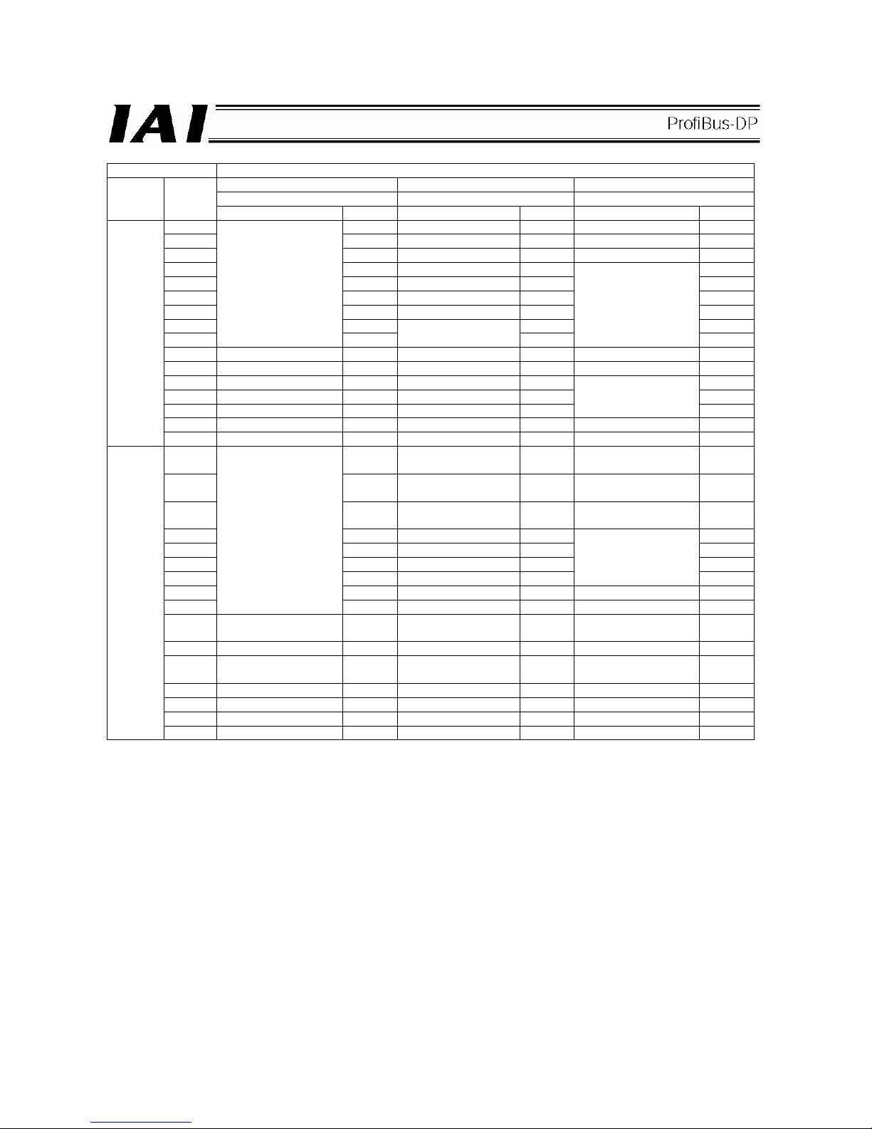
50
Setting of parameter No. 25
512-point mode Solenoid valve mode 1 Solenoid valve mode 2
3 4 5
Category Port No.
Signal name Symbol Signal name Symbol Signal name Symbol
0 PC1 Start position 0 ST0 Start position 0 ST0
1 PC2 Start position 1 ST1 Start position 1 ST1
2 PC4 Start position 2 ST2 Start position 2 ST2
3 PC8 Start position 3 ST3 4 PC16 Start position 4 ST4 5 PC32 Start position 5 ST5 6 PC64 Start position 6 ST6 7 PC128 - 8
Command position
number
PC256
Cannot be used.
-
Cannot be used.
-
9 Forced brake release BKRL Forced brake release BKRL Forced brake release BKRL
10 Operation mode RMOD Operation mode RMOD Operation mode RMOD
11 Home return HOME Home return HOME 12 Pause *STP Pause *STP 13 Positioning start CSTR Cannot be used. -
Cannot be used.
-
14 Reset RES Reset RES Reset RES
Input
15 Servo ON command SON Servo ON command SON Servo ON command SON
0 PM1 Completed position 0 PE0
Rear end move
command 0
LS0
1 PM2 Completed position 1 PE1
Rear end move
command 1
LS1
2 PM4 Completed position 2 PE2
Rear end move
command 2
LS2
3 PM8 Completed position 3 PE3 -
4 PM16 Completed position 4 PE4 -
5 PM32 Completed position 5 PE5 -
6 PM64 Completed position 6 PE6
Cannot be used.
7 PM128 Zone 1 ZONE1 Zone 1 ZONE1
8
Completed position
number
PM256 Position zone PZONE Position zone PZONE
9
Operation mode
output
RMDS
Operation mode
output
RMDS Cannot be used. RMDS
10 Home return complete HEND Home return complete HEND Home return complete HEND
11
Positioning complete
signal
PEND
Positioning complete
signal
PEND
Positioning complete
signal
-
12 Operation ready SV Operation ready SV Operation ready SV
13 Emergency stop *EMGS Emergency stop *EMGS Emergency stop *EMGS
14 Alarm *ALM Alarm *ALM Alarm *ALM
Output
15 Battery alarm *BALM Battery alarm *BALM Battery alarm *BALM
* indicates a signal that is normally ON.
The signals denoted by “Cannot be used” are not controlled. (ON/OFF statuses of these signals are
indeterminable.)
The battery alarm signal is always ON (fixed) when an incremental encoder is used.
Page 55

51
(7) Correspondence of RCS-C, E-Con and SCON I/O port numbers and PLC addresses
In the assignment of the RCS-C, E-Con or SCON’s ProfiBus-DP board I/Os in the input/output (memory) areas of
the PLC, one word of input/output area is occupied by 16 I/O points (dedicated inputs/outputs) of the slave
station.
The table below is an example of how I/O addresses are set when a RCS-C controller (eight dedicated input
points, 10 dedicated output points), E-Con controller (10 dedicated input points, 12 dedicated output points) and
SCON controller (16 dedicated input points, 16 dedicated output points) are connected as slave stations to the
master station.
[1] Example of system configuration
An example of system configuration is shown below.
[2] Address assignment in the master station
When setting the configuration in [1] using a configurator, the numbers of inputs and outputs set for slave
station 2 must be set.
(Here, it is assumed that the number of occupiable slave stations is set to eight words in the PLC master
station.)
The respective I/Os are assigned addresses (bit addresses) as viewed from the PLC.
CPU
Bus station
number
Station 1 Station 2
Power supply
ProfiBus-DP
master station
Slave station 1
(RCS-C: Eight input points, 10 output points)
Slave station 2
(E-con: 10 input points, 13 output points)
Slave station 3
(SCON: 16 input points, 16 output points)
Slave station 4 (16 input points)
Page 56
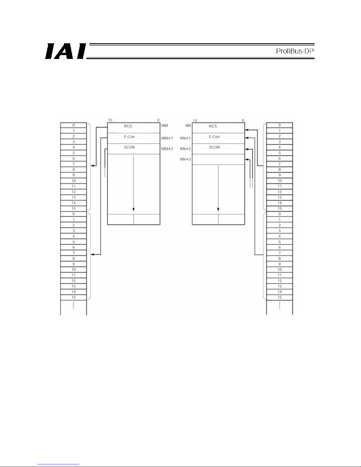
52
I/O port numbers are assigned in units of 16 points starting from the channel address in the PLC buffer
memory corresponding to the specified node address. Here, the PLC buffer memory bits are sequentially
assigned to the I/O port numbers, starting from the smallest port number and lowest memory bits.
Accordingly, the PLC addresses are assigned as follows.
(Note) NN and MM are PLC channel addresses corresponding to node address nn.
Since node addresses (nn, nn+1, nn+2, and so on) are occupied according to the numbers of I/O points
used, pay attention to duplicate node address settings.
Input port number
(bit address)
PLC output buffer memory
bit position
Channel
address
PLC input buffer memory
bit position
Output port number
(bit address)
8input points
10 input points
16 input points
16 input points
10 output points
12 output points
16 output points
Page 57
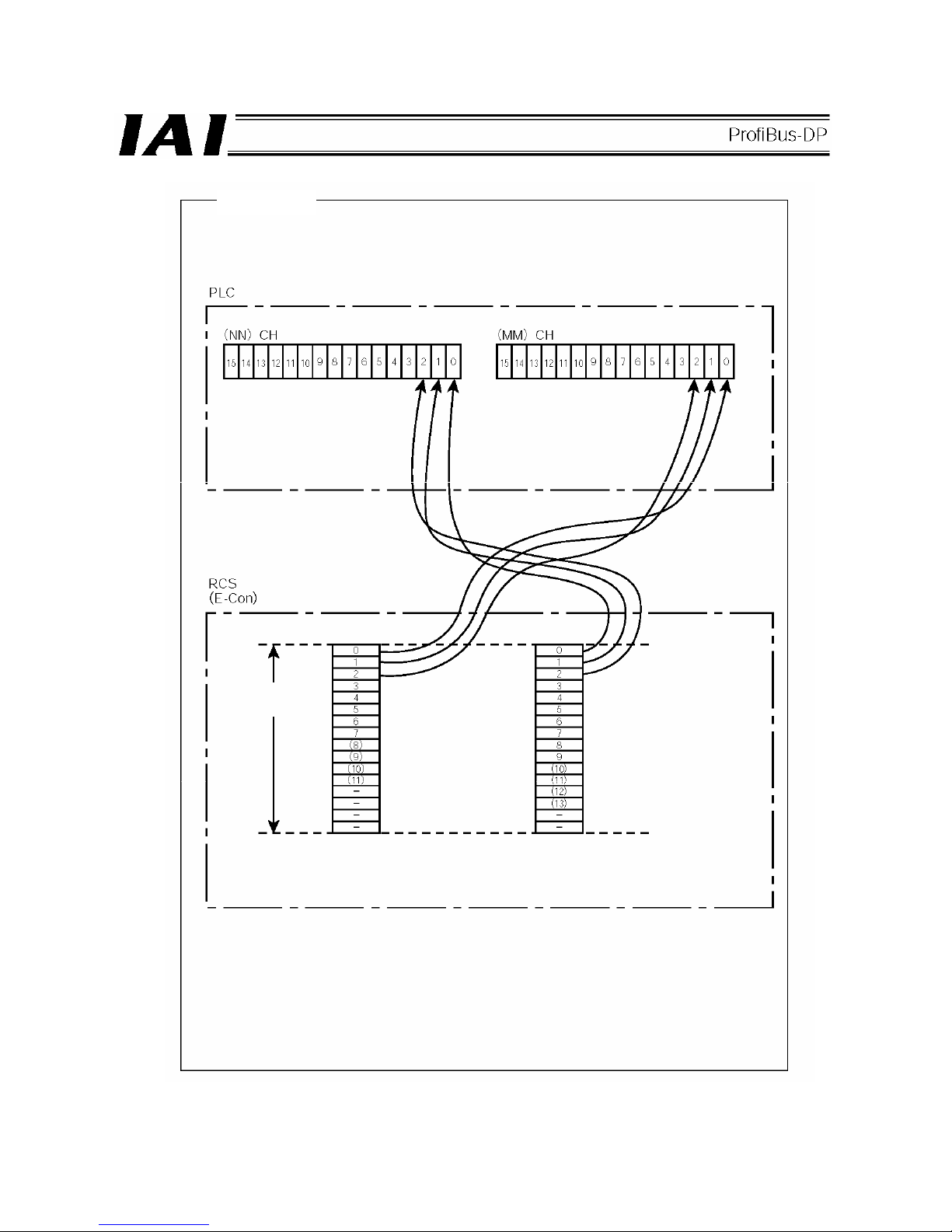
53
Reference 1
When bit addresses are set in the PLC, inputs and outputs are sequentially assigned to
the channels corresponding to the node address set by the DIP switches.
(Input) (Output)
Node address
nn
The numbers under (NN)/(MM) CH are PLC channel addresses corresponding to node
address nn.
Input number Output number
* The settings in ( ) apply to the E-Con.
Page 58

54
Example of address assignment rules --- Fuji Electric
Prefix
Bus station number
This number indicates the installation position of the ProfiBus-DP board in the PLC.
Word number
A sequential number specifying a word when the I/Os assigned to the master station are arranged in words.
Bit address
A sequential number specifying a bit when the I/Os assigned within each word above are arranged in bits.
Prefix Word number Bit address
Bus station
number
Input bit address (address per bit)
Input word address (address per word)
Output bit address (address per bit)
Output word address (address per word)
CPU
Station 1 Station 2
Power supply
ProfiBus-DP
master station
Reference 2
Page 59

55
6. ASEL, PSEL, SSEL
ASEL, PSEL and SSEL controllers of ProfiBus type can support up to 256 input points and 256 output points.
6.1 Models
6.1.1 ASEL, PSEL
ASEL and PSEL controllers of ProfiBus type are indicated by the following model numbers:
1-axis type
ASEL-C-1--PR-
PSEL-C-1--PR-
2-axis type
ASEL-C-2--PR-
PSEL-C-2--PR-
External view
Status LEDs
ProfiBus communication
connector
Printed series name
• ASEL
• PSEL
Front panel color
• ASEL: Dark blue
• PSEL: Dark green
Page 60

56
6.1.2 SSEL
SSEL controllers of ProfiBus type are indicated by the following model numbers:
1-axis type
SSEL-C-1--PR-
2-axis type
SSEL-C-1--PR-
External view
Status LEDs
ProfiBus communication
connector
Front panel color
Dark gray
Printed series name
Page 61

57
6.2 ProfiBus Interface
(1) Name of each part
• ASEL, PSEL • SSEL
(2) Status LED indications
The operating condition of the ProfiBus board, as well as the network condition, can be checked using the two
LEDs (STATUS0 and STATUS1) provided on the front side of the board.
LED Color
Indicator
condition
Description of indication
Lit The board is online and communicating properly.
Green
Blinking
The board is online and the settings have been cleared by the
master following an error.
Blinking at 1 Hz A network I/O parameter error is present.
Orange
Blinking at 2 Hz A configuration error is present.
STATUS1
- Unlit The controller power is not supplied.
Lit Initialization has completed and the board is operating properly.
Green
Blinking
After the completion of initialization, a network diagnostic
message was received from a configurator, etc., and a response
has been returned.
Orange Lit Exceptional error (controller failure, etc.)
STATUS2
- Unlit
• Initialization not yet completed
• The controller power is not supplied.
Status LEDs
ProfiBus communication
connector
Page 62

58
Page 63

59
(3) ProfiBus-DP communication connector
The board-end connector is a D-sub 9-pin (female) connector recommended under the ProfiBus-DP standard
EN50170.
The network connector on the other end is not supplied.
Pin No. Signal name Explanation
1 NC Not connected
2 NC Not connected
3 B-Line Communication line B (positive side)
4 NC Not connected
5 GND Signal ground
6 +5V +5-V output
7 NC Not connected
8 A-Line Communication line A (negative side)
9 NC Not connected
Housing Shield Cable shield
Caution
(1) The baud rate is automatically set according to the corresponding setting on the master side and thus
need not be set.
(2) Set the node address using I/O parameter No. 226.
(3) No terminal resistor setting switch is provided. If the connector is to be connected to the network
terminal node, connect the terminal resistor to the network connector as shown below or use a
connector with terminal resistor.
z Connecting the terminal resistor
z ProfiBus connector (with terminal resistor)
(Example) SUBCON-PLUS-PROFIB/AX/SC (Phoenix Contact)
Board-end female
connector
Network-end male connector
(from counter-insertion side)
Network
wiring
Page 64

60
6.3 I/O Parameter Settings
Set the node address, I/O ports and other parameters of the ASEL, PSEL and SSEL used with ProfiBus.
(1) Network type setting
I/O parameter No. 225, “Network I/F module: Control” has been set to 3H (ProfiBus) at the factory. (No additional
setting is required.)
(2) Node address
Set the node address using I/O parameter No. 226, “Network I/F module: Communication attribute 1.” The setting
range is 0 to 125. This parameter has been set to 1H at the factory.
(Note) If the specified address is outside the setting range, a “D75: Fieldbus parameter error” will occur.
(3) I/O part assignments
In the following I/O parameters, assign the numbers of physical I/O ports and ports for the ASEL, PSEL or SSEL
controller you want to use in your ProfiBus system:
No. 1 “I/O port assignment type”
No. 14 “Network I/F module: Remote input ports used”
No. 15 “Network I/F module: Remote output ports used”
No. 16 “Network I/F module fixed assignment: Initial input port number”
No. 17 “Network I/F module fixed assignment: Initial output port number”
For details, refer to the ASEL, PSEL, SSEL Network I/O Parameter Table on the following page.
(Note) With ASEL, PSEL and SSEL controllers, the following I/O parameters are invalid when a ProfiBus module
is used. Even if these parameters are set, they will not affect the numbers of ProfiBus ports used,
assigned port numbers, etc.:
No. 2 “
Standard I/O fixed assignment: Initial input port number (I/O1)”
No. 3
“Standard I/O fixed assignment: Initial output port number (I/O1)”
No. 10 “Standard I/O error monitor”
(4) Network error monitor
Set whether or not to monitor errors using I/O parameter No. 18, “Network I/F module: Error monitor.” Set the error
check time using bits 4 to 11 of I/O parameter No. 120, “Network attribute 1.”
If a network link error continues for the time specified in parameter No. 120 or longer, a system error will occur.
For details, refer to the ASEL, PSEL, SSEL Network I/O Parameter Table on the following page.
See 6.4.
Page 65
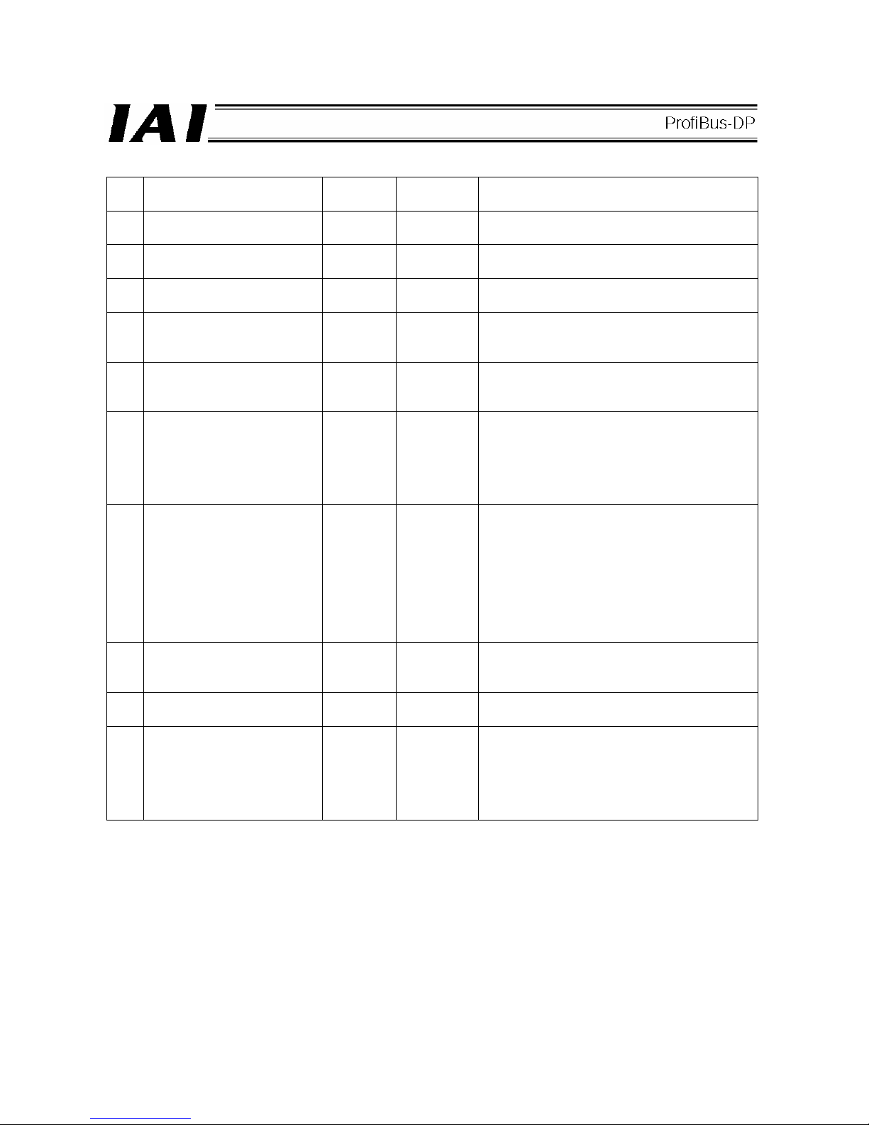
61
ASEL, PSEL and SSEL Network I/O Parameter List
No. Parameter name
Factory-set
value
Input range Remarks
1
Input/output port assignment
type
0 0 ~ 20
0: Fixed assignment
1: Automatic assignment
14
Network I/F module: Remote
input ports used
64 0 ~ 256 Multiple of 8
15
Network I/F module: Remote
output ports used
64 0 ~ 256 Multiple of 8
16
Network I/F module fixed
assignment: Initial input port
number
0 -1 ~ 599
0 + (multiple of 8) (The parameter is invalid if a
negative value is set.)
17
Network I/F module fixed
assignment: Initial output port
number
300 -1 ~ 599
300 + (multiple of 8) (The parameter is invalid if a
negative value is set.)
18
Network I/F module: Error
monitor
1 0 ~ 5
0: Not monitored 1: Monitored
* If a network link error continues for the
network link error check timer period or
longer,
a system error will occur. (Refer to I/O
parameter No. 120.)
* Some exceptions apply.
120
Network attribute 1
1
H
0
H
~
FFFFFFFF
H
Bits 0 to 3: Reserved by system
Bits 4 to 11: Network link error check timer
period (set in units of 10 msec)
Valid only when I/O parameter No. 18 = 1.
(Example) If the set value is 05H (bits 4 to 11),
the timer period becomes 50 ms
(10 ms x 5). If the set value is 0H, a
system error occurs immediately
due to a network link error.
225
Network I/F module: Control
3
H
For
reference
only
Bits 0 to 3: Network I/F module type
(0: Not installed, 1: CC-Link module,
2: DeviceNet module, 3: ProfiBus module)
226
Network I/F module:
Communication attribute 1
1 0 ~ 999
Node address of network I/F module
* If a ProfiBus module is used: 0 to 125
227
Network I/F module:
Communication attribute 2
0
H
0
H
~
FFFFFFFF
H
Bits 0 to 3: Baud rate type of network I/F
module
* If a ProfiBus module is used, the baud rate is
automatically set according to the
corresponding setting on the master side and
thus need not be set.
Page 66

62
6.4 I/O Port Numbers and ProfiBus-DP Address Assignments
ASEL, PSEL and SSEL controllers operate in the program mode and positioner mode, but the principles of
assignment are the same with both modes. To be specific, I/O port numbers are assigned in units of 16 points
starting from the channel address in the PLC buffer memory corresponding to the specified node address. Here,
the PLC buffer memory bits are sequentially assigned to the I/O port numbers, starting from the smallest port
number and lowest memory bits.
(1) Basic example
The correlation diagram shown below assumes the following settings of I/O parameters:
No. 16 = 0 (Initial input port number)
No. 17 = 300 (Initial output port number)
No. 14 = No.15 = 16 (Numbers of input and output ports)
No. 226 = nn (Node address)
(Note) NN and MM are PLC channel addresses corresponding to node address nn.
Since node addresses (nn, nn+1, nn+2, and so on) are occupied according to the numbers of I/O points
used, pay attention to duplicate node address settings.
Input port number
(bit address)
PLC output buffer memory
bit position
Channel
address
PLC input buffer memory
bit position
Output port number
(bit address)
Page 67

63
(2) Positioner mode
Regardless of the settings of I/O parameter Nos. 1, 16 and 17, physical ports are assigned from No. 0 for input
ports and from No. 300 for output ports.
As shown in the I/O port table on the next pageand subsequent pages, input ports of Nos. 0 to 23 and output
ports of Nos. 300 to 307 are used.
In this case, both I/O parameter Nos. 14 and 15 are set to 24.
(Note) Set the same number of points for I/O parameter Nos. 14 and 15 according to the number of input or
output ports, whichever is greater.
Page 68

64
ASEL Positioner Mode I/O Port Table
Positioner mode
Category
Port
No.
Standard mode
Product-type
switching mode
2-axis independent
mode
Teaching mode
DC-S-C1
compatible mode
16 Position input 10 Input 10 Position input 7 Axis 1 jog-
Position No. 1000
input
17 Position input 11 Input 11 Position input 8 Axis 2 jog+ 18 Position input 12 Input 12 Position input 9 Axis 2 jog- 19 Position input 13 Input 13 Position input 10 Inching (0.01 mm) 20 Position input 14 Input 14 Position input 11 Inching (0.1 mm) 21 - Input 15 Position input 12 Inching (0.5 mm) 22 - Input 16 Position input 13 Inching (1 mm) (Fixed to OFF)
23 - Error reset Error reset Error reset CPU reset
0 Start Start Axis 1 start Start Start
1 Home return Home return Home return Servo on Pause
2 Servo on Servo on Axis 1 servo ON *Pause Cancellation
3 Push Push *Axis 1 pause Position input 1
Interpolation
setting
4 *Pause *Pause
*Axis 1
cancellation
Position input 2 Position input 1
5 *Cancellation *Cancellation Axis 2 start Position input 3 Position input 2
6 Interpolation Interpolation Axis 2 home return Position input 4 Position input 4
7 Position input 1 Input 1 Axis 2 servo ON Position input 5 Position input 8
8 Position input 2 Input 2 *Axis 2 pause Position input 6 Position input 10
9 Position input 3 Input 3
*Axis 2
cancellation
Position input 7 Position input 20
10 Position input 4 Input 4 Position input 1 Position input 8 Position input 40
11 Position input 5 Input 5 Position input 2 Position input 9 Position input 80
12 Position input 6 Input 6 Position input 3 Position input 10 Position input 100
13 Position input 7 Input 7 Position input 4 Position input 11 Position input 200
14 Position input 8 Input 8 Position input 5
Specifying
teaching mode
Position input 400
Input
15 Position input 9 Input 9 Position input 6 Axis 1 jog+ Position input 800
300 *Alarm *Alarm *Alarm *Alarm Alarm
301 Ready Ready Ready Ready Ready
302
Positioning
compete
Positioning
compete
Axis 1 positioning
complete
Positioning
compete
Positioning
compete
303
Home return
complete
Home return
complete
Axis 1 home return
complete
Home return
complete
-
304 Servo ON output Servo ON output Axis 1 servo ON Servo ON output -
305 Push complete Push complete
Axis 2 positioning
complete
-
306
System battery
error
System battery
error
Axis 2 home return
complete
System battery
error
System battery
error
Output
307
Absolute battery
error
Absolute battery
error
Axis 2 servo ON
Absolute battery
error
Absolute battery
error
*: Contact B (negative logic)
Page 69

65
PSEL Positioner Mode I/O Port Table
Positioner mode
Category
Port
No.
Standard mode
Product-type
switching mode
2-axis independent
mode
Teaching mode
DC-S-C1
compatible mode
16 Position input 10 Input 10 Position input 7 Axis 1 jog-
Position No. 1000
input
17 Position input 11 Input 11 Position input 8 Axis 2 jog+ 18 Position input 12 Input 12 Position input 9 Axis 2 jog- 19 Position input 13 Input 13 Position input 10 Inching (0.01 mm) 20 - Input 14 Position input 11 Inching (0.1 mm) 21 - Input 15 Position input 12 Inching (0.5 mm) 22 - Input 16 Position input 13 Inching (1 mm) (Fixed to OFF)
23 Error reset Error reset Error reset Error reset CPU reset
0 Start Start Axis 1 start Start Start
1 Home return Home return Home return Servo on Pause
2 Servo on Servo on Axis 1 servo ON *Pause Cancellation
3 Push Push *Axis 1 pause Position input 1
Interpolation
setting
4 *Pause *Pause
*Axis 1
cancellation
Position input 2 Position input 1
5 *Cancellation *Cancellation Axis 2 start Position input 3 Position input 2
6 Interpolation Interpolation Axis 2 home return Position input 4 Position input 4
7 Position input 1 Input 1 Axis 2 servo ON Position input 5 Position input 8
8 Position input 2 Input 2 *Axis 2 pause Position input 6 Position input 10
9 Position input 3 Input 3
*Axis 2
cancellation
Position input 7 Position input 20
10 Position input 4 Input 4 Position input 1 Position input 8 Position input 40
11 Position input 5 Input 5 Position input 2 Position input 9 Position input 80
12 Position input 6 Input 6 Position input 3 Position input 10 Position input 100
13 Position input 7 Input 7 Position input 4 Position input 11 Position input 200
14 Position input 8 Input 8 Position input 5
Specifying
teaching mode
Position input 400
Input
15 Position input 9 Input 9 Position input 6 Axis 1 jog+ Position input 800
300 *Alarm *Alarm *Alarm *Alarm Alarm
301 Ready Ready Ready Ready Ready
302
Positioning
compete
Positioning
compete
Axis 1 positioning
complete
Positioning
compete
Positioning
compete
303
Home return
complete
Home return
complete
Axis 1 home return
complete
Home return
complete
-
304 Servo ON output Servo ON output Axis 1 servo ON Servo ON output -
305 Push complete Push complete
Axis 2 positioning
complete
-
306
System battery
error
System battery
error
Axis 2 home return
complete
System battery
error
System battery
error
Output
307 - - Axis 2 servo ON - -
*: Contact B (negative logic)
Page 70

66
SSEL Positioner Mode I/O Port Table
Positioner mode
Category
Port
No.
Standard mode
Product-type
switching mode
2-axis independent
mode
Teaching mode
DC-S-C1
compatible mode
16 Position input 10 Input 10 Position input 7 Axis 1 jog-
Position No. 1000
input
17 Position input 11 Input 11 Position input 8 Axis 2 jog+
Position No. 2000
input
18 Position input 12 Input 12 Position input 9 Axis 2 jog-
Position No. 4000
input
19 Position input 13 Input 13 Position input 10 Inching (0.01 mm)
Position No. 8000
input
20 Position input 14 Input 14 Position input 11 Inching (0.1 mm)
Position No. 10000
input
21 Position input 15 Input 15 Position input 12 Inching (0.5 mm)
Position No. 20000
input
22 Position input 16 Input 16 Position input 13 Inching (1 mm) (Fixed to OFF)
23 Error reset Error reset Error reset Error reset CPU reset
0 Start Start Axis 1 start Start Start
1 Home return Home return Home return Servo on Pause
2 Servo on Servo on Axis 1 servo ON *Pause Cancellation
3 Push Push *Axis 1 pause Position input 1
Interpolation
setting
4 *Pause *Pause
*Axis 1
cancellation
Position input 2 Position input 1
5 *Cancellation *Cancellation Axis 2 start Position input 3 Position input 2
6 Interpolation Interpolation Axis 2 home return Position input 4 Position input 4
7 Position input 1 Input 1 Axis 2 servo ON Position input 5 Position input 8
8 Position input 2 Input 2 *Axis 2 pause Position input 6 Position input 10
9 Position input 3 Input 3
*Axis 2
cancellation
Position input 7 Position input 20
10 Position input 4 Input 4 Position input 1 Position input 8 Position input 40
11 Position input 5 Input 5 Position input 2 Position input 9 Position input 80
12 Position input 6 Input 6 Position input 3 Position input 10 Position input 100
13 Position input 7 Input 7 Position input 4 Position input 11 Position input 200
14 Position input 8 Input 8 Position input 5
Specifying
teaching mode
Position input 400
Input
15 Position input 9 Input 9 Position input 6 Axis 1 jog+ Position input 800
300 *Alarm *Alarm *Alarm *Alarm Alarm
301 Ready Ready Ready Ready Ready
302
Positioning
compete
Positioning
compete
Axis 1 positioning
complete
Positioning
compete
Positioning
compete
303
Home return
complete
Home return
complete
Axis 1 home return
complete
Home return
complete
-
304 Servo ON output Servo ON output Axis 1 servo ON Servo ON output -
305 Push complete Push complete
Axis 2 positioning
complete
-
306
System battery
error
System battery
error
Axis 2 home return
complete
System battery
error
System battery
error
Output
307
Absolute battery
error
Absolute battery
error
Axis 2 servo ON
Absolute battery
error
Absolute battery
error
*: Contact B (negative logic)
Page 71
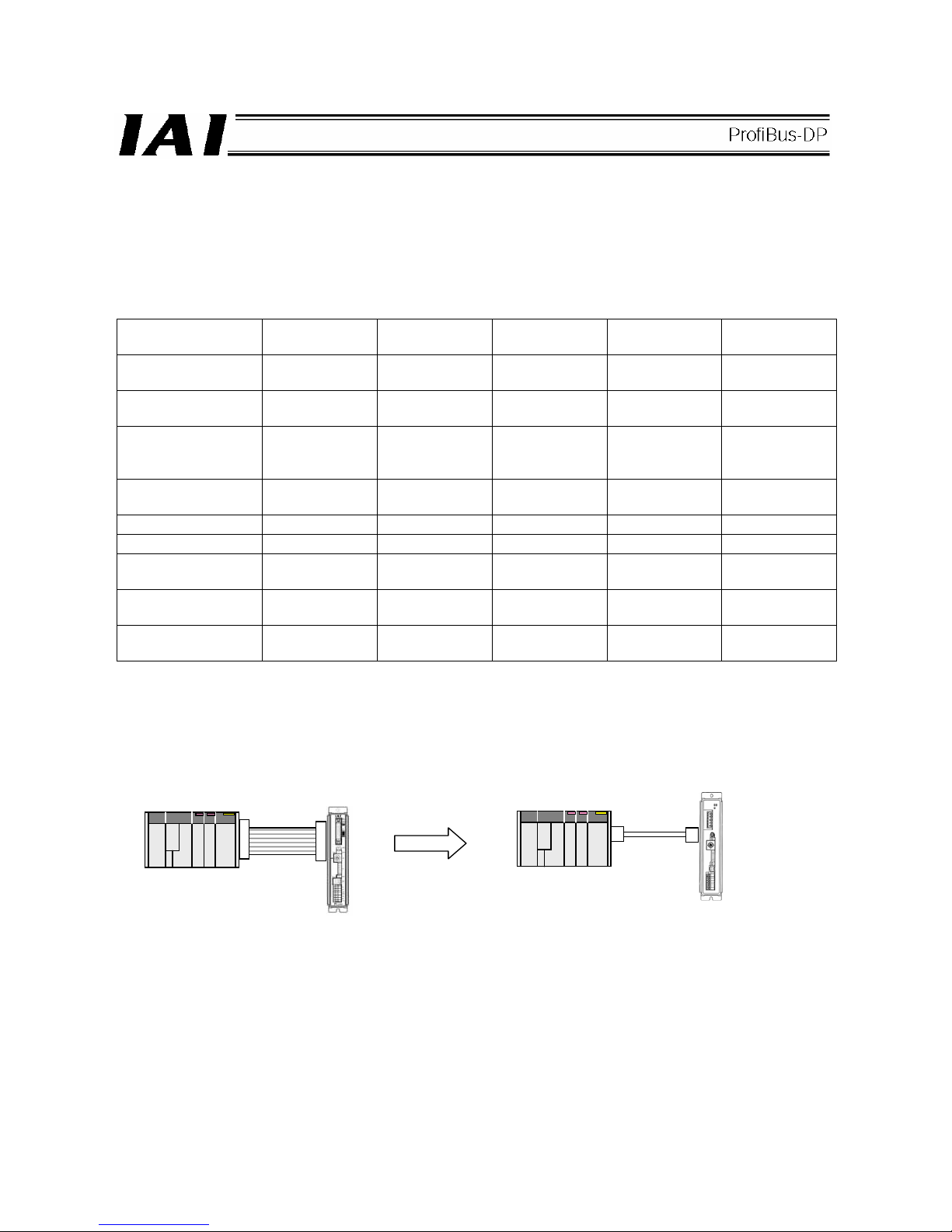
67
7. ACON, PCON
7.1 Operation Modes and Functions
ACON and PCON controllers supporting ProfiBus-DP can be operated in a desired operation mode selected from
the following five modes.
Operation Modes and Key Functions
Key function
Remote I/O
mode
Position/simple
direct mode
Half direct mode Full direct mode
Remote I/O
mode 2
Number of occupied
bytes
2 8 16 32 12
Operation by position
data specification
x { (*1)
{ {
x
Direct
speed/acceleration
specification
x x
{ {
x
Push-motion
operation
{ { { { {
Current position read x
{ { { {
Current speed read x x
{ { {
Operation by position
number specification
{ {
x x
{
Completed position
number read
{ {
x x
{
Maximum position
table size
512 768 Not used Not used 512
(*1) The actuator is operated by specifying all position data, other than positions, using position numbers.
[1] Remote I/O mode: In this mode, the actuator is operated by PIOs (24-V I/Os) via ProfiBus-DP communication.
Number of occupied bytes: 2 bytes (1 word)
PLC
PLC
Flat cable
Communication
cable
A
CON/PCON not
supporting ProfiBus-DP
PIO connection
A
CON/PCON supporting
ProfiBus-DP
ProfiBus-DP connection
Page 72

68
[2] Position/simple direct mode: In this mode, the actuator is operated by specifying position numbers.
You can select whether to specify the target position directly as a value, or use
a value registered in the position data table, by switching a control signal.
For the speed, acceleration/deceleration, positioning band, etc., values
preregistered in the position data table are used. Up to 768 position data points
can be set.
Number of occupied bytes: 8 bytes (4 words)
[3] Half direct mode: In this mode, the actuator is operated by specifying the speed, acceleration/deceleration
and push current, in addition to the target position, directly as values.
Number of occupied bytes: 16 bytes (8 words)
PLC
Target position: 100.00 mm
+
Position No. 0
A
CON/PCON supporting
ProfiBus-DP
A
ctuator
Speed
A
cceleration
Deceleration
Push
PLC
Target position: 100.00 mm
Positioning band: 0.10 mm
Speed specification: 100.0
mm/sec
A
cceleration/deceleration:
0.30 G
Push current: 50%
A
CON/PCON supporting
ProfiBus-DP
A
ctuator
Zone +
Zone -
Threshold
Page 73
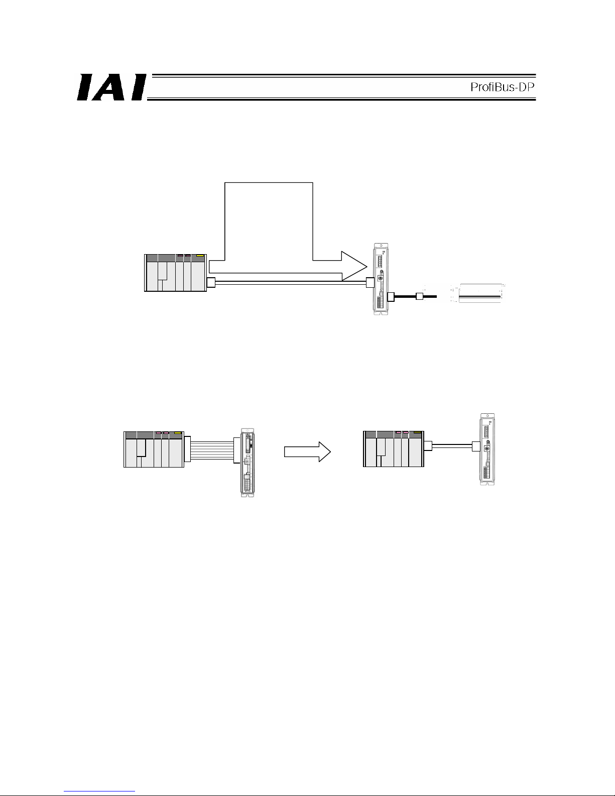
69
[4] Full direct mode: In this mode, the actuator is operated by specifying all values relating to position control
(target position, speed, acceleration/deceleration, etc.) directly as values.
Number of occupied bytes: 32 bytes (16 words)
[5] Remote I/O mode 2: In this mode, the actuator is operated by PIOs (24-V I/Os) via ProfiBus-DP
communication.
The current-position and command-current read functions are available in addition to
the functions provided in mode [1].
Number of occupied bytes: 12 bytes (6 words)
PLC
Target position: 100.00 mm
Positioning band: 0.10 mm
Speed specification: 100.0
mm/sec
A
cceleration: 0.30 G
Deceleration: 0.30 G
Push current: 50%
Load current threshold: 0
Zone+: 50.00 mm
Zone-: 30.00 mm
A
CON/PCON supporting
ProfiBus-DP
A
ctuator
PLC
PLC
Flat cable
Communication
cable
A
CON/PCON not
supporting ProfiBus-DP
A
CON/PCON supporting
ProfiBus-DP
ProfiBus-DP connection
PIO connection
Page 74

70
7.2 Models
The models of ACON and PCON controller supporting ProfiBus-DP are indicated as follows, respectively:
z ACON-C/CG--PR-
z PCON-C/CG--PR-
Printed series name
z ACON
z PCON
Front panel color
z ACON: Dark blue
z PCON: Dark green
Page 75

71
7.3 ProfiBus-DP (Slave Station) Settings
(1) Name of each part
The name of each part relating to ProfiBus-DP is shown.
(2) ProfiBus-DP communication connector interface specifications
This is a 9-pin, female D-sub connector recommended by the ProfiBus-DP standard EN 50170.
Connector
Pin No. Description Contents
3 B-Line RxD, TxD (Positive signal line)
4 RTS Request to send
5 GND Signal ground (insulation)
6 +5V +5-V output (insulation)
8 A-Line /RxD, /TxD (Negative signal line)
Housing Shield Cable shield (enclosure and connection)
(Note 1) Pins 1, 2, 7 and 9 are not used (they need not be wired).
(Note 2) The cable-end connector is not supplied.
1
STATUS
0
SV
A
LM
Status indicator LEDs
Status LEDs
ProfiBus-DP communication connector
Page 76

72
(3) Bus terminal processing
If the connector is to be connected to the network terminal node, connect the terminal resistor to the ProfiBus-DP
communication connector as shown below or use a connector with terminal resistor.
z Example of connector with terminal resistor: SUBCON-PLUS-PROFIB/AX/SC (Phoenix Contact)
z Connecting the terminal resistor
(4) Operation mode selection (setting)
Set a desired operation mode using a parameter.
Set the mode selector switch on the front side of the controller to the MANU position, and then set parameter No.
84, “FMOD: Fieldbus operation mode” using the RC PC software (V6.00.05.00 or later). (Refer to 7.7,
“Parameters.”)
Set value Operation mode
Number of
occupied bytes
0 (factory setting) Remote I/O mode 2
1 Position/simple direct mode 8
2 Half direct mode 16
3 Full direct mode 32
4 Remote I/O mode 2 12
* If a greater value is entered, an excessive input error will occur.
(5) Node address setting
Set the node address using a parameter.
Set parameter No. 85, “NADR: Fieldbus node address” using the RC PC software. (Refer to 7.7, “Parameters.”)
Settable range: 0 to 125 (The parameter has been set to 1 at the factory.)
(Note 1) Pay attention to duplicate node address settings.
(Note 2) ProfiBus-DP node addresses are set with the master station always having address 0. Accordingly,
addresses of slave stations can be set between 1 and 125.
Board-end female
connector
Network-end male connector
(from counter-insertion side)
Network
wiring
Page 77

73
(6) Status LED indications
The board operating condition and network condition can be checked using the two LEDs provided on the front
side of the controller.
LED Color
Indicator
condition
Description of indication (Meaning of indication)
Lit
The board is online with the fieldbus network and communicating
normally.
Green
Blinking The board is offline from the fieldbus network.
STATUS1
Orange Blinking A communication error is present.
Lit The board is operating properly.
Green
Blinking The board is not yet ready.
STATUS0
Orange Lit
A communication hardware error was detected when the board
was not yet ready.
(Note 1) After the necessary parameters have been set, reconnect the controller power and return the mode
selector switch on the front side of the controller to the AUTO position. If the switch remains in the
MANU position, PLC operation cannot be performed.
(Note 2) The baud rate is automatically set according to the corresponding setting on the master side and
thus need not be set.
Page 78

74
7.4 Communication with the Master Station
7.4.1 Operation Modes and Handling of PLC Addresses
The address assignments under each operation mode are shown below.
• PLC output → ACON/PCON input (* n indicates the initial output address for each axis.)
ACON/PCON DI and input data resister
Remote I/O
mode
Position/simple
direct mode
Half direct mode Full direct mode
Remote I/O
mode 2
PLC output
address (word
address)
Number of
occupied bytes: 2
Number of
occupied bytes: 8
Number of
occupied bytes: 16
Number of
occupied bytes: 32
Number of
occupied bytes: 12
n
Port number 0 to
15
Port number 0 to
15
n+1
Target position Target position Target position
n+2
Specified position
number
n+3
Control signal
Positioning band Positioning band
n+4
Speed
n+5
Acceleration/
deceleration
Speed
specification
Occupied area
n+6
Push-current
limiting value
n+7
Control signal
Zone boundary+
n+8
n+9
Zone boundary-
n+10
Acceleration
n+11
Deceleration
n+12
Push-current
limiting value
ACON
Occupied
area
n+13
PCON
Load
current
threshold
n+14
Control signal 1
n+15
Control signal 2
(Note) The “occupied area” is occupied according to the operation mode setting.
This area cannot be used for any other purpose. Also pay attention to use of duplicate addresses.
Page 79

75
• ACON/PCON output → PLC input (* n indicates the initial input address for each axis.)
ACON/PCON DO and output data resister
Remote I/O
mode
Position/simple
direct mode
Half direct mode Full direct mode
Remote I/O
mode 2
PLC input
address (word
address)
Number of
occupied bytes: 2
Number of
occupied bytes: 8
Number of
occupied bytes: 16
Number of
occupied bytes: 32
Number of
occupied bytes: 12
n
Port number 0 to
15
Port number 0 to
15
n+1
Current position Current position Current position
Occupied area
n+2
Completed position
number (simple
alarm ID)
n+3
Status signal
Command current Command current Current position
n+4
n+5
Current speed Current speed Command current
n+6
Alarm code Alarm code
n+7
Status signal
n+8
n+9
n+10
n+11
n+12
n+13
n+14
Occupied area
n+15
Status signal
(Note) The “occupied area” is occupied according to the operation mode setting.
This area cannot be used for any other purpose. Also pay attention to use of duplicate addresses.
Page 80
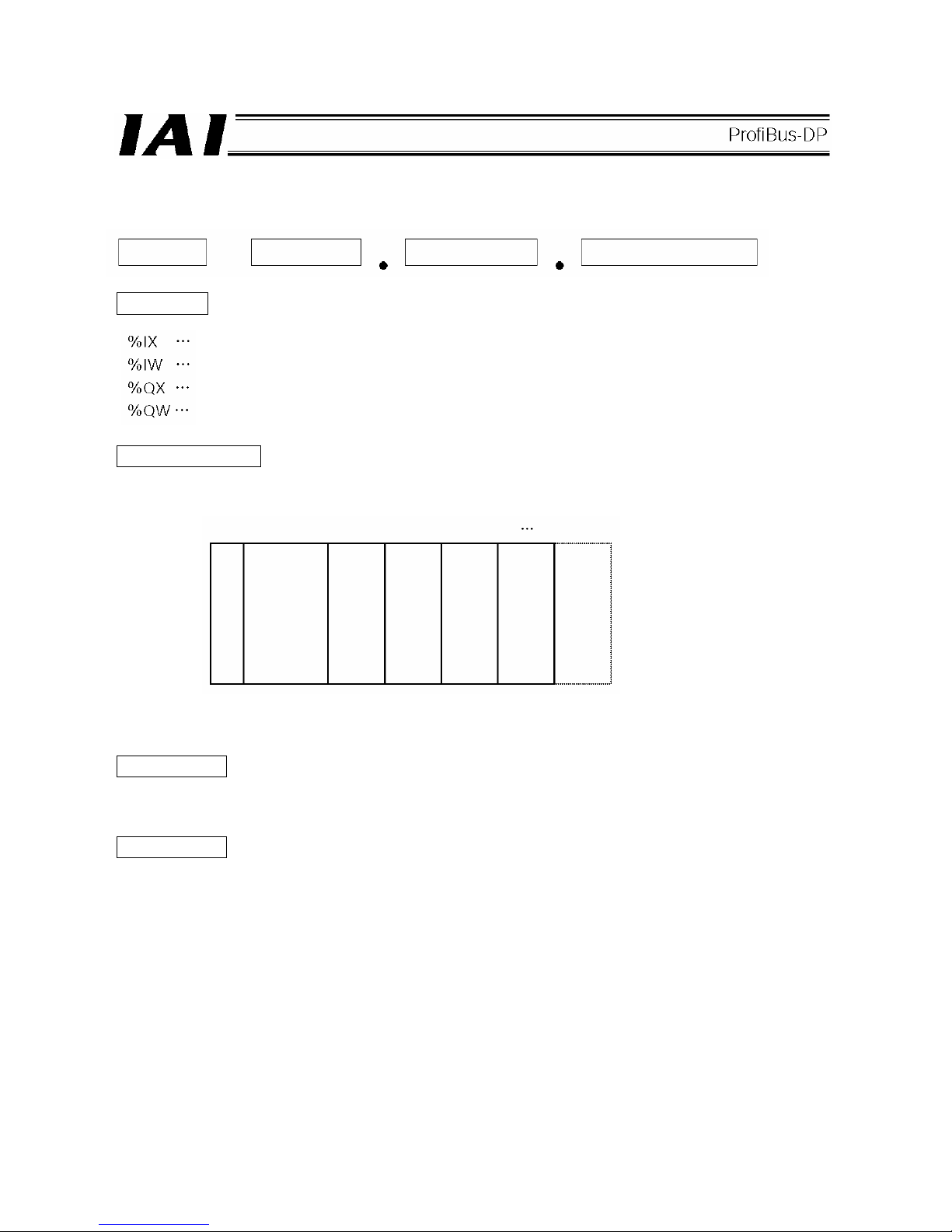
76
z Reference: Example of PLC address assignment rules --- Fuji Electric
The PLC address assignment rules are shown below.
Prefix
Bus station number
This number indicates the installation position of the ProfiBus-DP master unit within the PLC units is indicated.
Word address
Word addresses refer to addresses of DI/DOs and I/O data registers of an ACON or PCON assigned to the
master station, being arranged sequentially in units of words.
Bit address
Bit addresses refer to addresses of DI/DOs and I/O data registers of an ACON or PCON assigned to a word
address, being arranged sequentially in units of bits.
Prefix Word number Bit address
Bus station
number
Input bit address (address per bit)
Input word address (address per word)
Output bit address (address per bit)
Output word address (address per word)
CPU
Station 1 Station 2
Power supply
ProfiBus-DP
master station
Page 81

77
7.4.2 Remote I/O Mode (Number of Occupied Bytes: 2)
In this mode, the actuator is operated by specifying position numbers just like when PIOs (24-V I/Os) are used.
Set desired position data using the RC PC software or teaching pendant.
The number of positions to which the actuator can be operated varies according to the setting of parameter No.
25, “PIO pattern.”
The I/O specification of each PIO pattern is shown below. (For details, refer to the operation manual for the
controller.)
Setting of parameter No. 25
Operation mode I/O specification
0 Positioning mode 64 positioning points, 2 zone outputs
1 Teaching mode
64 positioning points, 1 zone output
Positioning and jog operations are supported.
The current position can be written under a specified position
number.
2 256-point mode 256 positioning points, 1 zone output
3 512-point mode 512 positioning points, no zone output
4
Solenoid valve
mode 1
7 positioning points, 2 zone outputs
An operation command can be specified directly for each
position number.
A positioning complete signal is output for each position
number.
5
Solenoid valve
mode 2
3 positioning points, 2 zone outputs
Operation using forward, reverse and interim position
commands.
A positioning complete signal is output individually for forward,
reverse and interim positions.
The key functions that are available on ROBO Cylinders controllable in this mode are shown in the table below.
PIO pattern
ROBO Cylinder
function
0:
Positioning
mode
1:
Teaching
mode
2:
256-point
mode
3:
512-point
mode
4:
Solenoid
valve mode 1
5:
Solenoid
valve mode 2
Home return operation
{ { { { {
x
Positioning operation
{ { { { { {
Speed &
acceleration/decelerati
on setting
{ { { { { {
Pitch feed (inching)
{ { { { { {
Push-motion operation
{ { { { {
X
Speed change during
movement
{ { { { { {
Operation at different
acceleration and
deceleration
{ { { { { {
Pause
{ { { { {
{ (*1)
Zone signal output
{ { {
x
{ {
PIO pattern selection
(set by parameter)
{ { { { { {
{: Supported, x: Not supported
(*1) This operation is supported when parameter No. 27, “Move command type” is set to “0.”
The actuator can be paused by turning the move command OFF.
Page 82
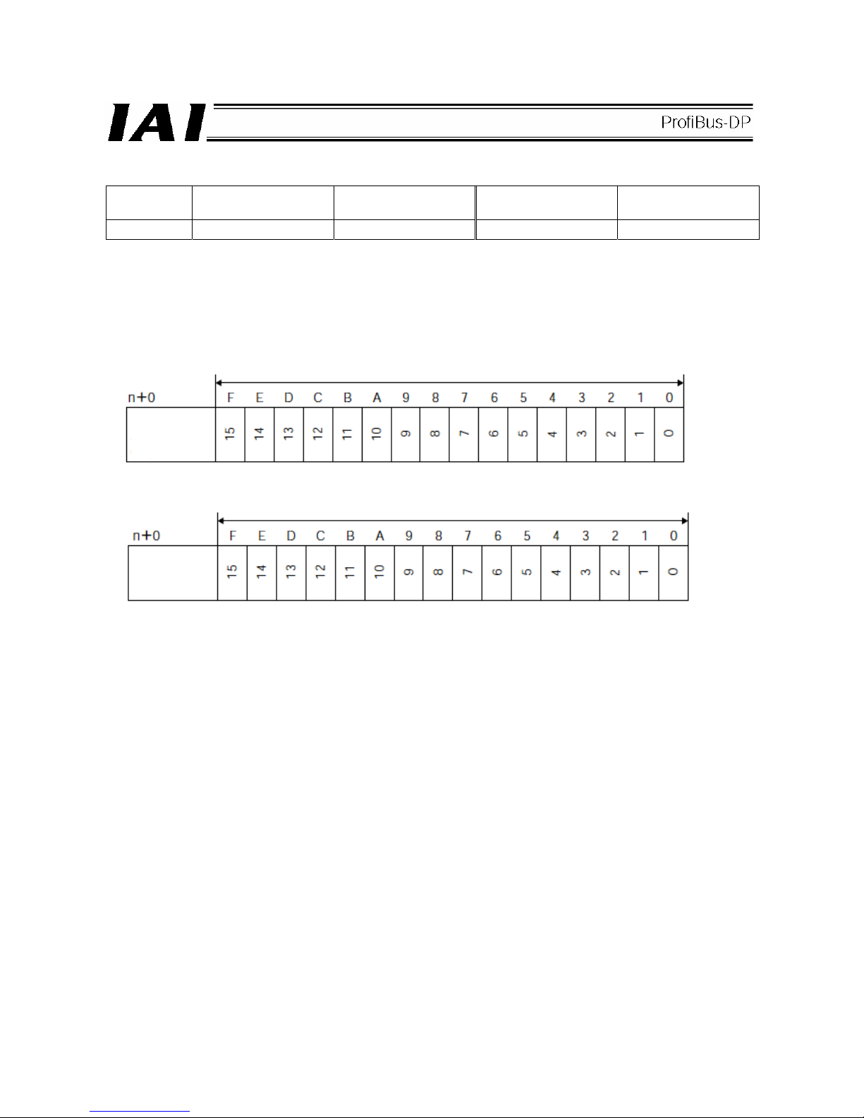
78
(1) PLC address configuration (* n indicates the initial input/output address for each axis.)
Parameter
No. 84
ACON/PCON DI
(port number)
PLC output address
ACON/PCON DO
(port number)
PLC input address
0 0 to 15 n 0 to 15 n
Pay attention to use of duplicate addresses.
(2) I/O signal assignments for each axis
An I/O signal of each axis consists of 1 word (2 bytes) of I/O addresses.
z I/O addresses are controlled by bit ON/OFF signals from the PLC.
PLC output
address
PLC input
address
(* n indicates the initial output address for each axis.)
1 word = 2 bytes = 16 bits
1 word = 2 bytes = 16 bits
(* n indicates the initial input address for each axis.)
Controller
input port
number
Controller
output port
number
Page 83

79
(3) I/O signal assignments
Which signals are assigned to controller I/O ports vary according to the setting of parameter No. 25.
(For details, refer to the operation manual for the controller.)
ACON
Setting of parameter No. 25
Positioning mode Teaching mode 256-point mode
0 1 2
Category Port No.
Signal name Symbol Signal name Symbol Signal name Symbol
0 PC1 PC1 PC1
1 PC2 PC2 PC2
2 PC4 PC4 PC4
3 PC8 PC8 PC8
4 PC16 PC16 PC16
5
Command position
number
PC32
Command position
number
PC32 PC32
6 -
Teaching mode
command
MODE PC64
7 - Jog/inching switching JISL
Command position
number
PC128
8
Cannot be used.
- +Jog JOG+ Cannot be used. -
9 Forced brake release BKRL -Jog JOG- Forced brake release BKRL
10 Operation mode RMOD Operation mode RMOD Operation mode RMOD
11 Home return HOME Home return HOME Home return HOME
12 Pause *STP Pause *STP Pause *STP
13 Positioning start CSTR
Positioning start /
Positioning data read
command
CSTR/
PWRT
Positioning start CSTR
14 Reset RES Reset RES Reset RES
PLC
output →
ACON
input
15 Servo ON command SON Servo ON command SON Servo ON command SON
0 PM1 PM1 PM1
1 PM2 PM2 PM2
2 PM4 PM4 PM4
3 PM8 PM8 PM8
4 PM16 PM16 PM16
5
Completed position
number
PM32
Completed position
number
PM32 PM32
6 Moving signal MOVE Moving signal MOVE PM64
7 Zone 1 ZONE1 Teaching mode signal MODES
Completed position
number
PM128
8 Position zone PZONE Position zone PZONE Position zone PZONE
9 Operation mode RMDS Operation mode RMDS Operation mode RMDS
10
Home return
complete
HEND Home return complete HEND Home return complete HEND
11
Positioning complete
signal
PEND
Positioning complete
signal/position data
read complete
PEND/
WEND
Positioning complete
signal
PEND
12 Operation ready SV Operation ready SV Operation ready SV
13 Emergency stop *EMGS Emergency stop *EMGS Emergency stop *EMGS
14 Alarm *ALM Alarm *ALM Alarm *ALM
ACON
output →
PLC
input
15 Cannot be used. - Cannot be used. - Cannot be used. -
* indicates a signal that is normally ON.
The signals denoted by “Cannot be used” are not controlled. (ON/OFF statuses of these signals are
indeterminable.)
Page 84
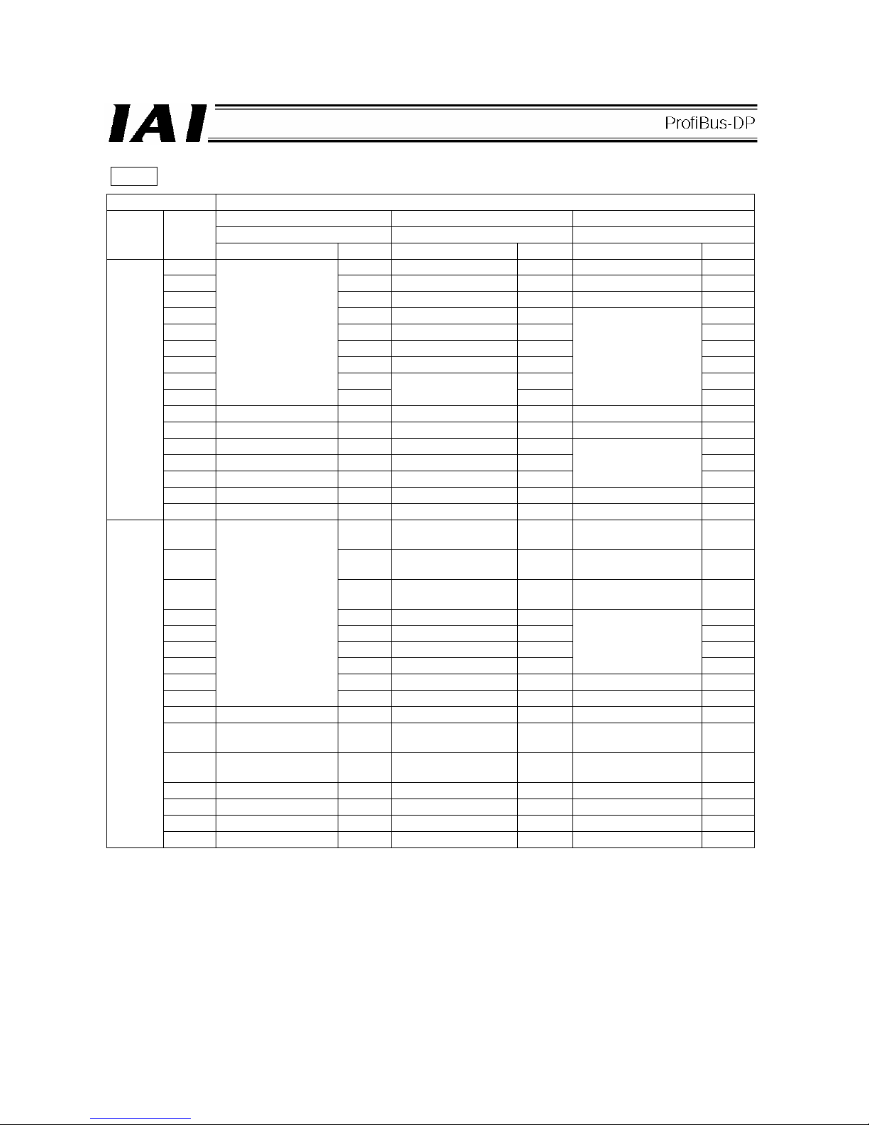
80
ACON
Setting of parameter No. 25
512-point mode Solenoid valve mode 1 Solenoid valve mode 2
3 4 5
Category Port No.
Signal name Symbol Signal name Symbol Signal name Symbol
0 PC1 Start position 0 ST0 Start position 0 ST0
1 PC2 Start position 1 ST1 Start position 1 ST1
2 PC4 Start position 2 ST2 Start position 2 ST2
3 PC8 Start position 3 ST3 4 PC16 Start position 4 ST4 5 PC32 Start position 5 ST5 6 PC64 Start position 6 ST6 7 PC128 - 8
Command position
number
PC256
Cannot be used.
-
Cannot be used.
-
9 Forced brake release BKRL Forced brake release BKRL Forced brake release BKRL
10 Operation mode RMOD Operation mode RMOD Operation mode RMOD
11 Home return HOME Home return HOME 12 Pause *STP Pause *STP 13 Positioning start CSTR Cannot be used. -
Cannot be used.
-
14 Reset RES Reset RES Reset RES
PLC
output →
ACON
input
15 Servo ON command SON Servo ON command SON Servo ON command SON
0 PM1 Completed position 0 PE0
Rear end move
command 0
LS0
1 PM2 Completed position 1 PE1
Rear end move
command 1
LS1
2 PM4 Completed position 2 PE2
Rear end move
command 2
LS2
3 PM8 Completed position 3 PE3 4 PM16 Completed position 4 PE4 5 PM32 Completed position 5 PE5 6 PM64 Completed position 6 PE6
Cannot be used.
7 PM128 Zone 1 ZONE1 Zone 1 ZONE1
8
Completed position
number
PM256 Position zone PZONE Position zone PZONE
9 Operation mode RMDS Operation mode RMDS Operation mode RMDS
10
Home return
complete
HEND Home return complete HEND Home return complete HEND
11
Positioning complete
signal
PEND
Positioning complete
signal
PEND Cannot be used. -
12 Operation ready SV Operation ready SV Operation ready SV
13 Emergency stop *EMGS Emergency stop *EMGS Emergency stop *EMGS
14 Alarm *ALM Alarm *ALM Alarm *ALM
ACON
output →
PLC
input
15 Cannot be used. - Cannot be used. - Cannot be used. -
* indicates a signal that is normally ON.
The signals denoted by “Cannot be used” are not controlled. (ON/OFF statuses of these signals are
indeterminable.)
Page 85
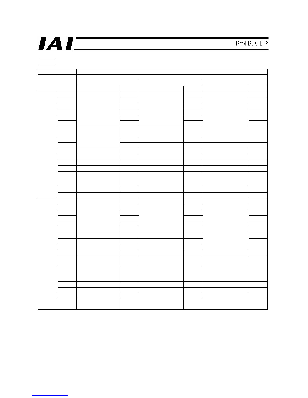
81
PCON
Setting of parameter No. 25
Positioning mode Teaching mode 256-point mode
0 1 2
Category Port No.
Signal name Symbol Signal name Symbol Signal name Symbol
0 PC1 PC1 PC1
1 PC2 PC2 PC2
2 PC4 PC4 PC4
3 PC8 PC8 PC8
4 PC16 PC16 PC16
5
Command position
number
PC32
Command position
number
PC32 PC32
6 -
Teaching mode
command
MODE PC64
7 - Jog/inching switching JISL
Command position
number
PC128
8
Cannot be used.
- +Jog JOG+ Cannot be used. -
9 Forced brake release BKRL -Jog JOG- Forced brake release BKRL
10 Operation mode RMOD Operation mode RMOD Operation mode RMOD
11 Home return HOME Home return HOME Home return HOME
12 Pause *STP Pause *STP Pause *STP
13 Positioning start CSTR
Positioning start /
Positioning data read
command
CSTR/
PWRT
Positioning start CSTR
14 Reset RES Reset RES Reset RES
PLC
output →
PCON
input
15 Servo ON command SON Servo ON command SON Servo ON command SON
0 PM1 PM1 PM1
1 PM2 PM2 PM2
2 PM4 PM4 PM4
3 PM8 PM8 PM8
4 PM16 PM16 PM16
5
Completed position
number
PM32
Completed position
number
PM32 PM32
6 Moving signal MOVE Moving signal MOVE PM64
7 Zone 1 ZONE1 Teaching mode signal MODES
Completed position
number
PM128
8 Position zone PZONE Position zone PZONE Position zone PZONE
9 Operation mode RMDS Operation mode RMDS Operation mode RMDS
10
Home return
complete
HEND Home return complete HEND Home return complete HEND
11
Positioning complete
signal
PEND
Positioning complete
signal/position data
read complete
PEND/
WEND
Positioning complete
signal
PEND
12 Operation ready SV Operation ready SV Operation ready SV
13 Emergency stop *EMGS Emergency stop *EMGS Emergency stop *EMGS
14 Alarm *ALM Alarm *ALM Alarm *ALM
PCON
output →
PLC
input
15
Load output
judgment/torque level
LOAD/
TRQS
Cannot be used. -
Load output
judgment/torque level
LOAD/
TRQS
* indicates a signal that is normally ON.
The signals denoted by “Cannot be used” are not controlled. (ON/OFF statuses of these signals are
indeterminable.)
Page 86

82
PCON
Setting of parameter No. 25
512-point mode Solenoid valve mode 1 Solenoid valve mode 2
3 4 5
Category Port No.
Signal name Symbol Signal name Symbol Signal name Symbol
0 PC1 Start position 0 ST0 Start position 0 ST0
1 PC2 Start position 1 ST1 Start position 1 ST1
2 PC4 Start position 2 ST2 Start position 2 ST2
3 PC8 Start position 3 ST3 4 PC16 Start position 4 ST4 5 PC32 Start position 5 ST5 6 PC64 Start position 6 ST6 7 PC128 - 8
Command position
number
PC256
Cannot be used.
-
Cannot be used.
-
9 Forced brake release BKRL Forced brake release BKRL Forced brake release BKRL
10 Operation mode RMOD Operation mode RMOD Operation mode RMOD
11 Home return HOME Home return HOME 12 Pause *STP Pause *STP 13 Positioning start CSTR Cannot be used. -
Cannot be used.
-
14 Reset RES Reset RES Reset RES
PLC
output →
PCON
input
15 Servo ON command SON Servo ON command SON Servo ON command SON
0 PM1 Completed position 0 PE0
Rear end move
command 0
LS0
1 PM2 Completed position 1 PE1
Rear end move
command 1
LS1
2 PM4 Completed position 2 PE2
Rear end move
command 2
LS2
3 PM8 Completed position 3 PE3 4 PM16 Completed position 4 PE4 5 PM32 Completed position 5 PE5 6 PM64 Completed position 6 PE6
Cannot be used.
7 PM128 Zone 1 ZONE1 Zone 1 ZONE1
8
Completed position
number
PM256 Position zone PZONE Position zone PZONE
9 Operation mode RMDS Operation mode RMDS Operation mode RMDS
10
Home return
complete
HEND Home return complete HEND Home return complete HEND
11 Positioning complete PEND Positioning complete PEND Cannot be used. 12 Operation ready SV Operation ready SV Operation ready SV
13 Emergency stop *EMGS Emergency stop *EMGS Emergency stop *EMGS
14 Alarm *ALM Alarm *ALM Alarm *ALM
PCON
output →
PLC
input
15
Load output
judgment/torque level
LOAD/
TRQS
Load output
judgment/torque level
LOAD/
TRQS
Cannot be used. -
* indicates a signal that is normally ON.
The signals denoted by “Cannot be used” are not controlled. (ON/OFF statuses of these signals are
indeterminable.)
Page 87
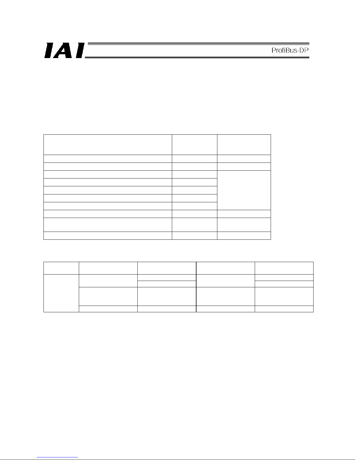
83
7.4.3 Position/Simple Direct Mode (Number of Occupied Bytes: 8)
In this mode, the actuator is operated by specifying position numbers. You can select whether to set the target
position directly as a value or use a value registered in the position data table, by switching a control signal
(PMOD signal).
For all data other than the target position, such as speed, acceleration/deceleration and positioning band, values
in the controller’s position table are used. Set desired position data by referring to the operation manual for the
controller.
Up to 768 position data points can be set.
The key functions that are available on ROBO Cylinders controllable in this mode are shown in the table below.
ROBO Cylinder function
{: Direct control
∆: Indirect control
x: Invalid
Remarks
Home return operation
{
Positioning operation
{
Speed & acceleration/deceleration setting
∆
Pitch feed (inching)
∆
Push-motion operation
∆
Speed change during movement
∆
Operation at different acceleration and deceleration
∆
Position data must
be set
Pause
{
Zone signal output
∆
Zones are set using
parameters.
PIO pattern selection
x
(1) PLC address configuration (* n indicates the initial input/output address for each axis.)
Parameter
No. 84
ACON/PCON input
register
PLC output address
ACON/PCON output
register
PLC input address
n+0 n+0
Target position
n+1
Current position
n+1
Specified position
number
n+2
Completed position
number
(simple alarm code)
n+2
1
Control signal n+3 Status signal n+3
(Note) Pay attention to use of duplicate addresses.
Page 88
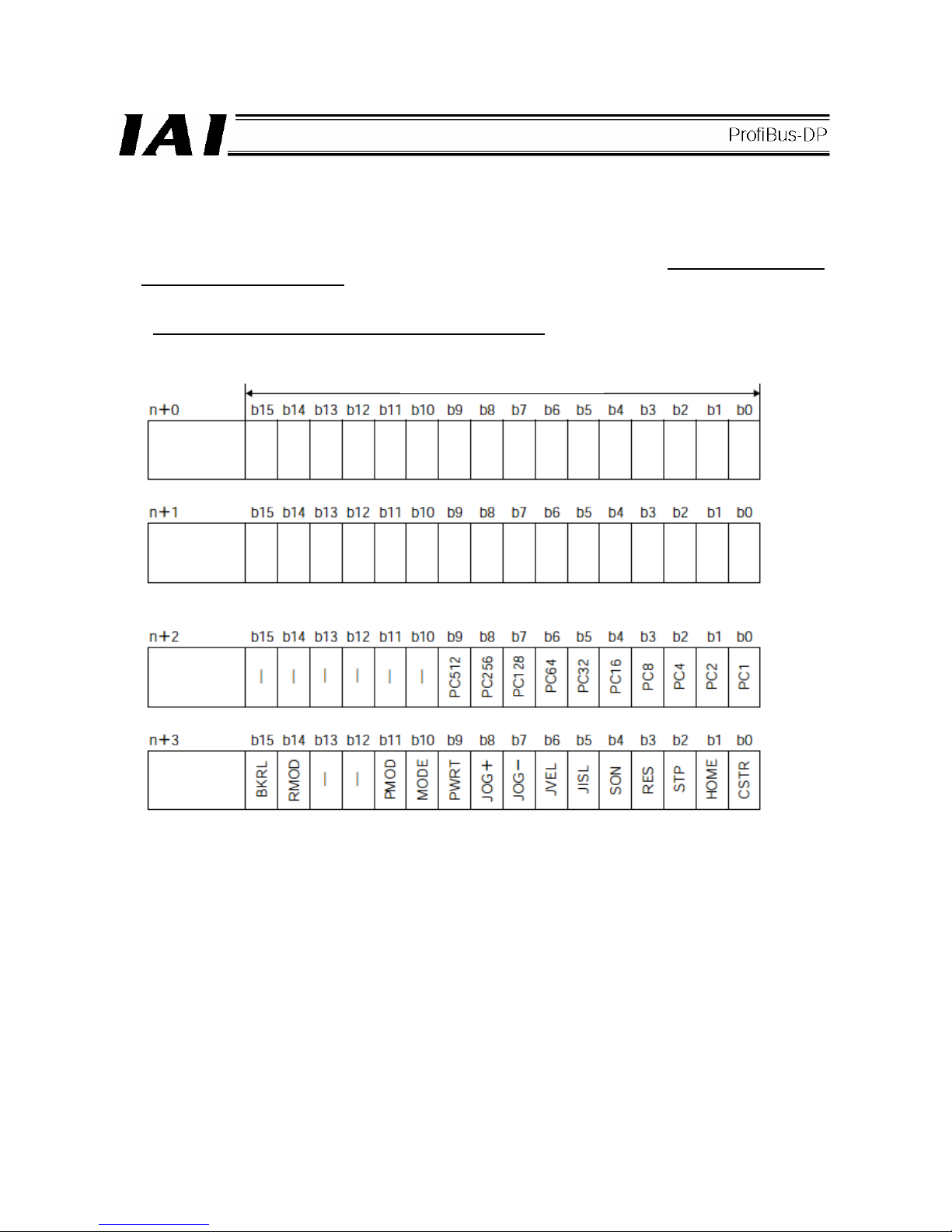
84
(2) I/O signal assignments for each axis
An I/O signal of each axis consists of 4 words (8 bytes) of I/O addresses.
z Control signals and status signals are bit ON/OFF signals.
z The target position and current position are both a 2-word (32-bit) binary data. Although values from -999999
to +999999 (unit: 0.01 mm) can be handled by the PLC, set position data within the software stroke range (0
up to the effective stroke length) of the applicable actuator.
z The specified position number and completed position number are both a 1-word (16-bit) binary data.
Although values from 0 to 767 can be handled by the PLC, use the PC software or teaching pendant to specify
a position number for which operation conditions are already set
.
PLC output
address
(* n indicates the initial output address for each axis.)
1 word = 2 bytes = 16 bits
Target
position
(upper word)
Target
position
(lower word)
Specified
position
number
Control signal
If the target position is a negative value, it is expressed by a 2’s complement.
Page 89

85
PLC input
address
(* n indicates the initial input address for each axis.)
1 word = 2 bytes = 16 bits
Current
position
(upper word)
Current
position
(lower word)
Complete
position
number
Status signal
If the current position is a negative value, it is expressed by a 2’s complement.
Page 90

86
(3) I/O signal assignments
(* In the table, ON indicates that the applicable bit is “1,” while OFF indicates that the applicable bit is “0.”)
Signal type Bit Symbol Description Details
Target position 32-bit data -
32-bit signed integer.
Specify the target position on the absolute coordinates.
The unit is 0.01 mm, while the specifiable range is -999999 to
999999.
(Example) To set +25.40 mm, specify “2540.”
If the entered value exceeds the range of soft limit parameters
(within 0.2 mm inside of the parameter values), the movement
will be limited to within the range of soft limits (within 0.2 mm
inside of the parameter values).
* If this data is entered using a hexadecimal, enter a negative
value as a 2’s complement.
7.6 (1)
Specified position
number
16-bit data
PC1 ~
PC512
16-bit integer.
To operate the actuator, position data is needed for which
operation conditions have already been entered using the PC
software or teaching pendant.
Use this register to specify the position number for which data
has been entered.
The specifiable range is 0 to 767.
If an out-of-range value is specified or the specified position
number is not yet set, an alarm will occur when the start signal
is turned ON.
7.6 (1)
b15 BKRL
Forced brake release: The brake is released when the signal
turns ON.
7.4.7 (18)
b14 RMOD
Operation mode: AUTO mode when the signal is OFF, or
MANU mode when the signal is ON.
7.4.7 (19)
b13
b12
- Cannot be used. -
b11 PMOD
Position/simple direct switching: Position mode when the
signal is OFF, or simple direct mode when the signal is ON.
7.4.7 (20)
b10 MODE
Teaching mode command: Normal mode when the signal is
OFF, or teaching mode when the signal is ON.
7.4.7 (16)
b9 PWRT
Position data read command: Position data is read when the
signal is ON.
7.4.7 (17)
b8 JOG+
+Jog: The actuator moves in the direction opposite home when
the signal is ON.
7.4.7 (13)
b7 JOG-
-Jog: The actuator moves in the direction of home when the
signal is ON.
7.4.7 (13)
b6 JVEL
Jog speed/inching distance switching: Parameter No. 26, “Jog
speed” and parameter No. 48, “Inching distance” are used
when the signal is OFF, or parameter No. 47, “Jog speed 2”
and parameter No. 49, “Inching distance 2” are used when the
signal is ON.
7.4.7 (14)
b5 JISL
Jog/inching switching: Jog operation when the signal is OFF,
or inching operation when the signal is ON.
7.4.7 (15)
b4 SON Servo ON command: The servo is ON when the signal is ON. 7.4.7 (5)
b3 RES Reset: A reset is performed when the signal turns ON. 7.4.7 (4)
b2 STP Pause: A pause command is issued when the signal turns ON. 7.4.7 (11)
b1 HOME
Home return: A home return command is issued when the
signal turns ON.
7.4.7 (6)
PLC output
Control signal
b0 CSTR
Positioning start: A move command is issued when the signal
turns ON.
7.4.7 (7)
Page 91

87
(* In the table, ON indicates that the applicable bit is “1,” while OFF indicates that the applicable bit is “0.”)
Signal type Bit Symbol Description Details
Current position 32 bit -
32-bit signed integer indicating the current position.
The unit is 0.01 mm.
(Example) Reading: 000003FFH = 1023 (decimal) = 10.23 mm
* If this data is read as a hexadecimal, a negative value is
indicated by a 2’s complement.
7.6 (1)
Completed
position number
(simple alarm
code)
16 bit
PM1 ~
PM512
16-bit integer.
After the actuator has moved to the target position and entered
the positioning band, the position number corresponding to the
completed positioning is output.
“0” is output when no position movement has been performed
yet or while the actuator is moving.
If an alarm occurs (= the ALM status signal turns ON), a
corresponding simple alarm code (refer to the operation
manual for the controller) will be output.
7.6 (1)
b15 EMGS
Emergency stop: An emergency stop is being executed when
the signal is ON.
7.4.7 (2)
b14 PWR
Controller ready: The signal turns ON when the controller
becomes ready.
7.4.7 (1)
b13 ZONE2
Zone 2: The signal is ON when the current position is inside
the specified zone.
7.4.7 (12)
b12 ZONE1
Zone 1: The signal is ON when the current position is inside
the specified zone.
7.4.7 (12)
b11 PZONE
Position zone: The signal is ON when the current position is
inside the specified position zone.
7.4.7 (12)
b10 MODES
Teaching mode signal: The signal is ON when the teaching
mode is selected.
7.4.7 (16)
b9 WEND
Position data read complete: The signal turns ON when the
position data read is complete.
7.4.7 (17)
b8 RMDS
Operation mode: The signal is OFF when the current mode
AUTO, or ON when the current mode is MANU.
7.4.7 (19)
b7
b6
- Cannot be used. -
b5 PSFL
Missed load during push-motion operation: The signal turns
ON when the actuator missed the load during push-motion
operation.
7.4.7 (23)
b4 SV Ready: The signal is ON when the servo is ON. 7.4.7 (5)
b3 ALM Alarm: The signal turns ON when an alarm occurs. 7.4.7 (3)
b2 MOVE Moving signal: The signal is ON while the actuator is moving. 7.4.7 (9)
b1 HEND
Home return complete: The signal turns ON when the home
return is completed.
7.4.7 (6)
PLC input
Status signal
b0 PEND
Positioning complete signal: The signal turns ON when the
positioning is completed.
7.4.7 (10)
Page 92

88
7.4.4 Half Direct Mode (Number of Occupied Bytes: 16)
In this mode, the actuator is operated by specifying the target position, positioning band, speed,
acceleration/deceleration and push current directly as values from the PLC.
Set each value in an applicable I/O address. If the zone function is used, set parameter Nos. 1, 2, 23 and/or 24.
The key functions that are available on ROBO Cylinders controllable in this mode are shown in the table below.
ROBO Cylinder function
{: Direct control
∆: Indirect control
x: Invalid
Remarks
Home return operation
{
Positioning operation
{
Speed & acceleration/deceleration setting
{
Pitch feed (inching)
{
Push-motion operation
{
Speed change during movement
{
Operation at different acceleration and deceleration
x
Pause
{
Zone signal output
∆
Parameters must be
set.
PIO pattern selection
x
(1) PLC address configuration (* n indicates the initial input/output address for each axis.)
Parameter
No. 84
ACON/PCON input
register
PLC output address
ACON/PCON output
register
PLC input address
n+0 n+0
Target position
n+1
Current position
n+1
n+2 n+2
Positioning band
n+3
Command current
n+3
Speed n+4 n+4
Acceleration/
deceleration
n+5
Current speed
n+5
Push-current limiting
value
n+6 Alarm code n+6
2
Control signal n+7 Status signal n+7
(Note) Pay attention to use of duplicate addresses.
Page 93

89
(2) I/O signal assignments for each axis
An I/O signal of each axis consists of 8 words (16 bytes) of I/O addresses.
z Control signals and status signals are bit ON/OFF signals.
z The target position and current position are both a 2-word (32-bit) binary data. Although values from -999999
to +999999 (unit: 0.01 mm) can be handled by the PLC, set position data within the software stroke range (0
up to the effective stroke length) of the applicable actuator.
z Set a desired positioning band. The positioning band is a 2-word (32-bit) binary data and values from 1 to
+999999 (unit: 0.01 mm) can be handled by the PLC.
z The specified speed is a 1-word (16-bit) binary data. Although values from 0 to +65535 (unit: 1.0 mm/sec) can
be handled by the PLC, set a value not exceeding the maximum speed
of the applicable actuator.
z The acceleration/deceleration is a 1-word (16-bit) binary data. Although values from 1 to 300 (unit: 0.01 G) can
be handled by the PLC, set a value not exceeding the maximum acceleration and maximum deceleration
of
the applicable actuator.
z The push-current limiting value is a 1-word (16-bit) binary data. Although values from 0 (0%) to 255 (100%)
can be handled by the PLC, set a value within the specifiable range of push-current limiting values
of the
applicable actuator (refer to the catalog or operation manual for the actuator).
z The command current is a 2-word (32-bit) binary data (unit: 1 mA).
z The current position is a 2-word (32-bit) binary data (unit: 0.01 mm/sec).
Positive value: The actuator is moving in the direction opposite home. / Negative value: The actuator is moving
in the direction of home.
z The alarm code is a 1-word (16-bit) binary data.
Set value
Push-current
limiting value
Page 94

90
PLC output
address
(* n indicates the initial output address for each axis.)
1 word = 2 bytes = 16 bits
Target
position
(upper word)
Target
position
(lower word)
Control signal
If the target position is a negative value, it is expressed by a 2’s complement.
Positioning
band (upper
word)
Positioning
band (lower
word)
Speed
A
cceleration/
deceleration
Push-current
limiting value
Page 95

91
PLC input
address
(* n indicates the initial input address for each axis.)
1 word = 2 bytes = 16 bits
Current
position
(upper word)
Current
position
(lower word)
If the current position is a negative value, it is expressed by a 2’s complement.
Command
current (upper
word)
Command
current (lower
word)
Current speed
(upper word)
Current speed
(lower word)
Alarm code
Status signal
If the current speed is a negative value, it is expressed by a 2’s complement.
Page 96

92
(3) I/O signal assignments
(* In the table, ON indicates that the applicable bit is “1,” while OFF indicates that the applicable bit is “0.”)
Signal type Bit Symbol Description Details
Target position 32-bit data -
32-bit signed integer.
Specify the target position on the absolute coordinates.
The unit is 0.01 mm, while the specifiable range is -999999 to
999999.
(Example) To set +25.41 mm, specify “2541.”
If the entered value exceeds the range of soft limit parameters
(within 0.2 mm inside of the parameter values), the movement
will be limited to within the range of soft limits (within 0.2 mm
inside of the parameter values).
* If this data is entered using a hexadecimal, enter a negative
value as a 2’s complement.
7.6 (2)
Positioning band 32-bit data -
32-bit integer.
The unit is 0.01 mm, while the specifiable range is 1 to 999999.
(Example) To set 25.40 mm, specify “2540.”
This register has one of two meanings depending on the
operation type:
[1] In the case of positioning operation, this register indicates
the allowable range from the target position within which
the positioning is deemed completed.
[2] In the case of push-motion operation, this register
indicates the push band. Use the control signal PUSH to
set whether to perform normal operation or push-motion
operation.
7.6 (2)
Speed 16-bit data -
16-bit integer.
Specify the speed at which to move the actuator.
The unit is 1.0 mm/sec, while the specifiable range is 0 to
65535.
(Example) To set 254.0 mm/sec, specify “254.”
If a move command is issued by specifying a value exceeding
the maximum speed, an alarm will occur.
7.6 (2)
PLC output
Acceleration/
deceleration
16-bit data -
16-bit integer.
Specify the acceleration/deceleration at which to move the
actuator. (The acceleration and deceleration become the same
value.)
The unit is 0.01 G, while the specifiable range is 1 to 300.
(Example) To set 0.30 G, specify “30.”
If a move command is issued by specifying “0” or a value
exceeding the maximum acceleration or maximum
deceleration, an alarm will occur.
7.6 (2)
Page 97
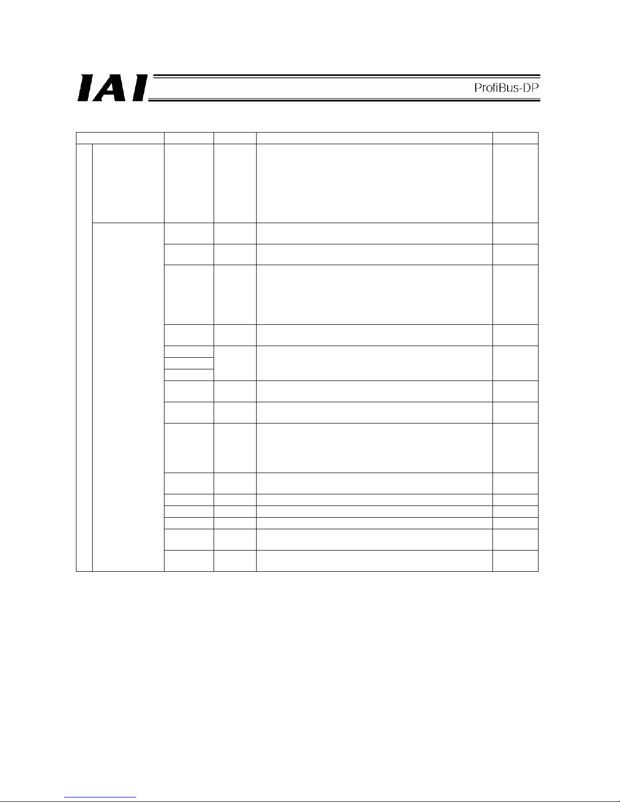
93
(* In the table, ON indicates that the applicable bit is “1,” while OFF indicates that the applicable bit is “0.”)
Signal type Bit Symbol Description Details
Push-current
limiting value
16-bit data -
16-bit integer.
Specify the current-limiting value during push-motion
operation.
The specified range is 0 (0%) to 255 (100%).
The actual specifiable range varies with each actuator. (Refer
to the catalog or operation manual for each actuator.)
If a move command is issued by specifying a value exceeding
the maximum push current value, an alarm will occur.
7.6 (2)
b15 BKRL
Forced brake release: The brake is released when the signal
turns ON.
7.4.7 (18)
b14 RMOD
Operation mode: AUTO mode when the signal is OFF, or
MANU mode when the signal is ON.
7.4.7 (19)
b13 DIR
Push direction specification:
When the signal is OFF, the direction of the position obtained
by subtracting the positioning band from the target position is
used.
When the signal is ON, the direction of the position obtained by
adding the positioning band to the target position is used.
7.4.7 (22)
b12 PUSH
Push specification: Positioning operation when the signal is
OFF, or push-motion operation when the signal is ON.
7.4.7 (21)
b11
b10
b9
- Cannot be used. -
b8 JOG+
+Jog: The actuator moves in the direction opposite home when
the signal is ON.
7.4.7 (13)
b7 JOG-
-Jog: The actuator moves in the direction of home when the
signal is ON.
7.4.7 (13)
b6 JVEL
Jog speed/inching distance switching: Parameter No. 26, “Jog
speed” and parameter No. 48, “Inching distance” are used
when the signal is OFF, or parameter No. 47, “Jog speed 2”
and parameter No. 49, “Inching distance 2” are used when the
signal is ON.
7.4.7 (14)
b5 JISL
Jog/inching switching: Jog operation when the signal is OFF,
or inching operation when the signal is ON.
7.4.7 (15)
b4 SON Servo ON command: The servo is ON when the signal is ON. 7.4.7 (5)
b3 RES Reset: A reset is performed when the signal turns ON. 7.4.7 (4)
b2 STP Pause: A pause command is issued when the signal turns ON. 7.4.7 (11)
b1 HOME
Home return: A home return command is issued when the
signal turns ON.
7.4.7 (6)
PLC output
Control signal
b0 DSTR
Positioning start command: A move command is issued when
the signal turns ON.
7.4.7 (8)
Page 98

94
(* In the table, ON indicates that the applicable bit is “1,” while OFF indicates that the applicable bit is “0.”)
Signal type Bit Symbol Description Details
Current position 32-bit data -
32-bit signed integer indicating the current position.
The unit is 0.01 mm.
(Example) Reading: 000003FFH = 1023 (decimal) = 10.23 mm
* If this data is read as a hexadecimal, a negative value is
indicated by a 2’s complement.
7.6 (2)
Command current 32-bit data -
32-bit integer.
The value of electrical current specified by the present
command is indicated.
The unit is mA.
(Example) Reading: 000003FFH = 1023 (decimal) = 1023 mA
7.6 (2)
Current speed 32-bit data -
32-bit signed integer.
The current speed is indicated.
Positive value: The actuator is moving in the direction opposite
home.
Negative value: The actuator is moving in the direction of
home.
The unit is 0.01 mm/sec.
(Example) Reading: 000003FFH = 1023 (decimal) = 10.23
mm/sec
* If this data is read as a hexadecimal value, a negative value
is indicated by a 2’s complement.
7.6 (2)
Alarm code 16-bit data -
16-bit integer.
If an alarm occurs, an alarm code will be output.
0H is output when no alarm is present.
For details on alarms, refer to the operation manual for the
controller.
7.6 (2)
b15 EMGS
Emergency stop: An emergency stop is being executed when
the signal is ON.
7.4.7 (2)
b14 PWR
Controller ready: The signal turns ON when the controller
becomes ready.
7.4.7 (1)
b13 ZONE2
Zone 2: The signal is ON when the current position is inside
the specified zone.
7.4.7 (12)
b12 ZONE1
Zone 1: The signal is ON when the current position is inside
the specified zone.
7.4.7 (12)
b11
b10
b9
- Cannot be used. -
b8 RMDS
Operation mode: The signal is OFF when the current mode
AUTO, or ON when the current mode is MANU.
7.4.7 (19)
b7
b6
- Cannot be used. -
b5 PSFL
Missed load during push-motion operation: The signal turns
ON when the actuator missed the load during push-motion
operation.
7.4.7 (23)
b4 SV Ready: The signal is ON when the servo is ON. 7.4.7 (5)
b3 ALM Alarm: The signal turns ON when an alarm occurs. 7.4.7 (3)
b2 MOVE Moving signal: The signal is ON while the actuator is moving. 7.4.7 (9)
b1 HEND
Home return complete: The signal turns ON when the home
return is completed.
7.4.7 (6)
PLC input
Status signal
b0 PEND
Positioning complete signal: The signal turns ON when the
positioning is completed.
7.4.7 (10)
Page 99
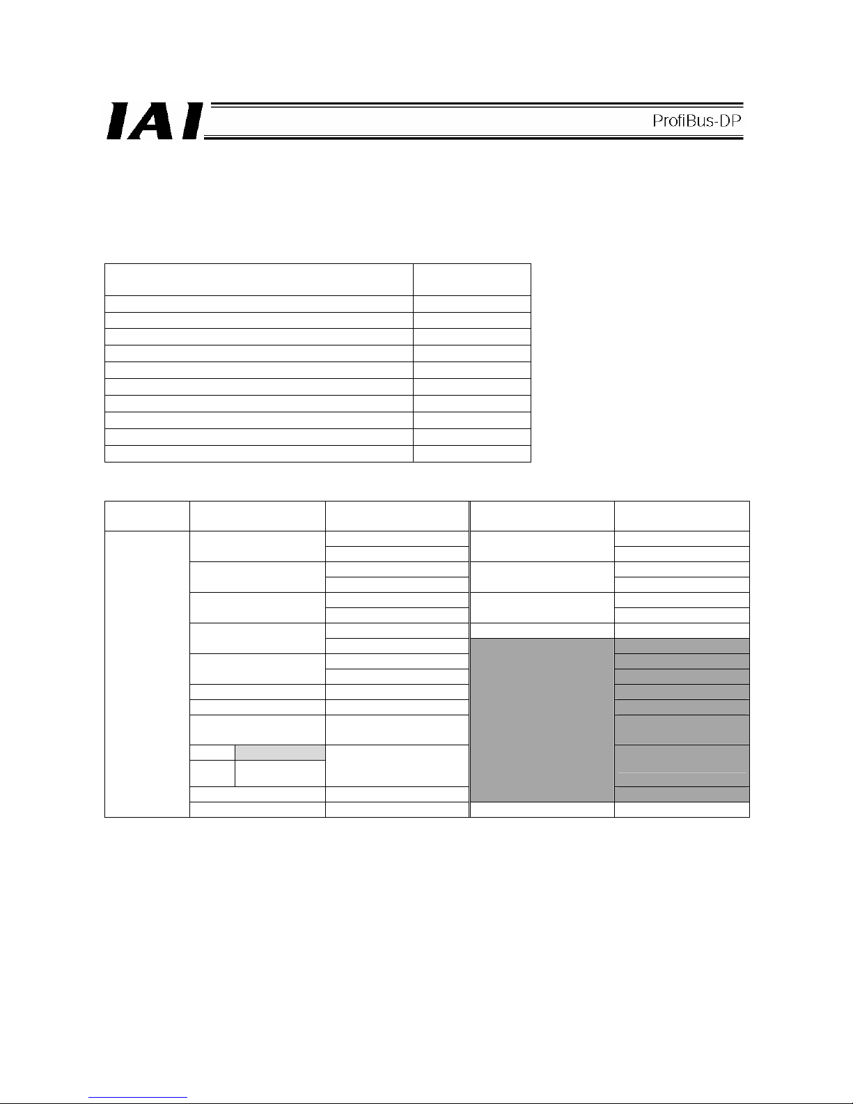
95
7.4.5 Full Direct Mode (Number of Occupied Bytes: 32)
In this mode, the actuator is operated by specifying all values relating to position control (target position, speed,
etc.) directly as values from the PLC.
Set each value in an I/O address.
The key functions that are available on ROBO Cylinders controllable in this mode are shown in the table below.
ROBO Cylinder function
{: Direct control
x: Invalid
Home return operation
{
Positioning operation
{
Speed & acceleration/deceleration setting
{
Pitch feed (inching)
{
Push-motion operation
{
Speed change during movement
{
Operation at different acceleration and deceleration
{
Pause
{
Zone signal output
{
PIO pattern selection
x
(1) PLC address configuration (* n indicates the initial input/output address for each axis.)
Parameter
No. 84
ACON/PCON input
register
PLC output address
ACON/PCON output
register
PLC input address
n+0 n+0
Target position
n+1
Current position
n+1
n+2 n+2
Positioning band
n+3
Command current
n+3
n+4 n+4
Speed
n+5
Current speed
n+5
n+6 Alarm code n+6
Zone boundary+
n+7
n+7
n+8 n+8
Zone boundary-
n+9
n+9
Acceleration n+10 n+10
Deceleration n+11 n+11
Push-current limiting
value
n+12
n+12
ACON
Occupied area
PCON
Load current
threshold
n+13 n+13
Control signal 1 n+14
Occupied area
n+14
3
Control signal 2 n+15 Status signal n+15
(Note) The [occupied area] cannot be used for any other purpose.
Also pay attention to use of duplicate addresses.
Page 100

96
(2) I/O signal assignments for each axis
An I/O signal of each axis consists of 16 words (32 bytes) of I/O addresses.
z Control signals 1 and 2 and status signals are bit ON/OFF signals.
z The target position and current position are both a 2-word (32-bit) binary data. Although values from -999999
to +999999 (unit: 0.01 mm) can be handled by the PLC, set position data within the software stroke range (0
up to the effective stroke length) of the applicable actuator.
z Set a desired positioning band. The positioning band is a 2-word (32-bit) binary data and values from 1 to
+999999 (unit: 0.01 mm) can be handled by the PLC.
z The speed is a 2-word (32-bit) binary data. Although values from 0 to 999999 (unit: 0.01 mm/sec) can be
handled by the PLC, set a value not exceeding the maximum speed
of the applicable actuator.
z The acceleration/deceleration is a 1-word (16-bit) binary data. Although values from 1 to 300 (unit: 0.01 G) can
be handled by the PLC, set a value not exceeding the maximum acceleration and maximum deceleration
of
the applicable actuator.
z The push-current limiting value is a 1-word (16-bit) binary data. Although values from 0 (0%) to 255 (100%)
can be handled by the PLC, set a value within the specifiable range of push-current limiting values
of the
applicable actuator (refer to the catalog or operation manual for the actuator).
z Set a desired load current threshold. The load current threshold is a 1-word (16-bit) binary data. Values from 0
(0%) to 255 (100%) can be handled by the PLC. (Refer to the graph of push-current limiting value (upper
graph).)
z The zone boundary+ and zone boundary- are both a 2-word (32-bit) binary data. Although values from
-999999 to +999999 (unit: 0.01 mm) can be handled by the PLC, set values so that the zone boundarybecomes smaller than the zone boundary+.
z The command current is a 2-word (32-bit) binary data (unit: 1 mA).
z The current position is a 2-word (32-bit) binary data (unit: 0.01 mm/sec).
Positive value: The actuator is moving in the direction opposite home. / Negative value: The actuator is moving
in the direction of home.
z The alarm code is a 1-word (16-bit) binary data.
Set value
Push-current
limiting value
 Loading...