

Page 1

Slider Type
First Edition ME3769-1A
RCS4- SA4C/SA6C/SA7C/SA8C
SA4R/SA6R/SA7R/SA8R
RCS4CR- SA4C/SA6C/SA7C/SA8C
Specifications
Installation
Maintenance and
Inspection
External Dimensions
Life
Warranty
Appendix
ROBO Cylinder
®
ch.
1
ch.
2
ch.
3
ch.
4
ch.
5
ch.
6
ch.
7
ch.
8
Instruction Manual
Connecting with
the Controller
Page 2

Page 3

Please Read Before Use
Thank you for purchasing our product.
This instruction manual explains the handling methods, structure and maintenance of this product,
providing the information you need in order to use the product safely.
Before using the product, be sure to read this manual and fully understand the contents explained
herein to ensure safe use of the product.
The DVD enclosed with the product contains instruction manuals for IAI products.
When using the product, refer to the necessary sections of the applicable instruction manual by
printing them out or displaying them on a PC.
After reading the instruction manual, keep it in a convenient place so that whoever is handling the
product can refer to it quickly when necessary.
[Important]
● This instruction manual is an original document dedicated for this product.
● This product cannot be used in ways not shown in this instruction manual. IAI shall not be
liable for any result whatsoever arising from the use of the product in any other way than what
is noted in the manual.
● The information contained in this instruction manual is subject to change without notice for the
purpose of product improvement.
● If any issues arise regarding the information contained in this instruction manual, contact our
customer center or the nearest sales office.
● Use or reproduction of this instruction manual in full or in part without permission is prohibited.
● The company names, names of products and trademarks of each company shown in the text
are registered trademarks.
Page 4

RCS4 Slider Type Instruction Manual Configuration
Product name Instruction manual name
Control
number
RCS4 First Step Guide ME3775
RCS4 Slider Type
Instruction Manual
(this document)
ME3769
SCON-CB/CFB Controller
SCON-CB/CFB Controller
Instruction Manual
ME0340
SCON-CAL/CGAL Controller
SCON-CAL/CGAL Controller
Instruction Manual
ME0243
MSCON-C Controller
MSCON-C Controller
Instruction Manual
ME0306
SSEL-CS Controller
SSEL-CS Controller
Instruction Manual
ME0157
XSEL-P/Q Controller
XSEL-P/Q Controller
Instruction Manual
ME0148
XSEL-R/S Controller
XSEL-R/S Controller
Instruction Manual
ME0313
XSEL-RA/SA Controller
XSEL-RA/SA Controller
Instruction Manual
ME0359
PC Compatible Software for RC/EC
RCM-101-MW/RCM-101-USB
Instruction Manual
ME0155
PC Compatible Software for XSEL
IA-101-X-MW/IA-101-X-USBMW
Instruction Manual
ME0154
Touch Panel Teaching Pendant
TB-01/01D/01DR
Applicable for Position Controller
Instruction Manual
ME0324
Touch Panel Teaching Pendant
TB-02/02D
Applicable for Position Controller
Instruction Manual
ME0355
Data Setter
TB-03
Applicable for Position Controller
ME0376
Touch Panel Teaching Pendant
TB-01/01D/01DR
Applicable for Program Controller
Instruction Manual
ME0325
Touch Panel Teaching Pendant
TB-02/02D
Applicable for Program Controller
Instruction Manual
ME0356
Data Setter
TB-03
Applicable for Program Controller
ME0377
Page 5

Contents
Safety Guide ···················································································· Intro-1
Precautions for Handling ···································································· Intro-9
International Standard Compliance ······················································· Intro-10
Names of the Parts ··········································································· Intro-11
Chapter 1 Specifications
1.1 Checking the product ································································ 1-1
Parts ··············································································································· 1-1
How to Read the Model Nameplate ········································································· 1-2
How to Read the Model Number ············································································ 1-2
Product list ········································································································ 1-3
1.2 Specifications ·········································································· 1-4
Specifications ····································································································· 1-4
Double Slider (Option) ·························································································· 1-28
Duty ratio ·········································································································· 1-29
1.3 Options ·················································································· 1-31
With brake (Model Code: B) ··················································································· 1-31
Cable Exit Direction Changed
(Model Code: CJT, CJR, CJL, CJB and CJO) ·················································· 1-31
High Precision Specifications (Model Code: HPR) ······················································ 1-31
Motor Reversed Direction (Model Code: ML, MR) ······················································· 1-31
Reversed-home Specification (Model Code: NM) ······················································· 1-31
Slider Roller Specification (Model Code: SR) ····························································· 1-32
Vacuum Joint Attachment Opposite Type (Model Code: VR)········································· 1-32
Double Slider Specification (Model Code: W) ···························································· 1-32
Rear Attachment Plate (Model Code: RP) ································································· 1-32
Slider spacer (Model Code: SS) ············································································· 1-33
1.4 Accessories ············································································ 1-35
Motor Cable ······································································································· 1-35
Encoder Cable ···································································································· 1-36
Chapter 2 Installation
2.1 Precautions for transportation ····················································· 2-1
2.2 Installation and storage/preservation environment ··························· 2-3
Installation Environment ······················································································· 2-3
Storage/preservation environment ·········································································· 2-4
2.3 How to Install ·········································································· 2-5
Installation Orientation ························································································· 2-5
Precautions regarding stainless steel sheet ······························································ 2-6
Installation surface ······························································································ 2-7
Installation of the Main Unit ··················································································· 2-8
Mounting transported objects ················································································· 2-16
About Suction of the Cleanroom Type ····································································· 2-19
Chapter 3 Connecting with the Controller
3.1 Connecting with the Controller ···················································· 3-1
Page 6

Chapter 4 Maintenance and Inspection
4.1 Precautions for maintenance and inspection work ··························· 4-1
4.2 Inspection Items and Schedule ··················································· 4-3
Slider type ········································································································· 4-3
Grease supply timing (Guideline) ············································································ 4-3
4.3 Visual inspection items ······························································ 4-4
External visual inspection ······················································································ 4-4
Internal visual inspection ······················································································· 4-5
4.4 Cleaning ················································································ 4-7
External cleaning ································································································ 4-7
Internal Cleaning ································································································· 4-7
4.5 Greasing method ····································································· 4-8
Grease used ······································································································ 4-8
Greasing method ································································································ 4-10
4.6 How to replace components ······················································· 4-13
Stainless steel sheet replacement/adjustment ··························································· 4-13
Belt replacement/adjustment ·················································································· 4-19
Motor Replacement ····························································································· 4-24
Chapter 5 External Dimensions
5.1 External Dimensions ································································· 5-1
RCS4-SA4C ······································································································· 5-1
RCS4-SA6C ······································································································· 5-2
RCS4-SA7C ······································································································· 5-3
RCS4-SA8C ······································································································· 5-4
RCS4-SA4R ······································································································· 5-5
RCS4-SA6R ······································································································· 5-7
RCS4-SA7R ······································································································· 5-8
RCS4-SA8R ······································································································· 5-10
RCS4CR-SA4C ·································································································· 5-12
RCS4CR-SA6C ·································································································· 5-13
RCS4CR-SA7C ·································································································· 5-14
RCS4CR-SA8C ·································································································· 5-15
Chapter 6 Life
6.1 Concept of life for slider type ······················································ 6-1
How to calculate operation life ················································································ 6-1
Relation between operation life and moment ····························································· 6-3
Chapter 7 Warranty
7.1 Warranty period ······································································· 7-1
7.2 Scope of the warranty ······························································· 7-1
7.3 Honoring the warranty ······························································· 7-1
7.4 Limited liability ········································································· 7-2
7.5 Conformance with applicable standards/regulations,etc.,
and application conditions ·························································· 7-2
7.6 Other Items excluded from warranty ············································· 7-2
Chapter 8 Appendix
8.1 Index ····················································································· 8-1
8.2 Revision history ······································································· 8-3
Page 7

Safety Guide
Intro-1
Safety Guide
The Safety Guide is intended to permit safe use of the product and thus to prevent risks and property
damage. Be sure to read it before handling the product.
Page 8

Safety Guide
Intro-2
Safety Precautions for Our Products
Common safety precautions for the use of robots in various operations are indicated here.
No. Operation Precautions
1 Model
Selection
● This product is not intended or designed for applications where high levels of
safety are required, and so cannot guarantee that human lives will be
protected. Accordingly, do not use it in any of the following applications.
(1) Medical equipment used to maintain, control or otherwise affect human life
or physical health
(2) Mechanisms or machinery designed for the purpose of moving or
transporting people (vehicles, railway facilities, aviation facilities etc.)
(3) Machinery components essential for safety (safety devices etc.)
● Do not use the product outside the range of the specifications. Otherwise,
the product life may be drastically shortened, and product damage or facilities
stoppage may occur.
● Do not use it in any of the following environments.
(1) Locations with flammable gases, ignitable objects or explosives
(2) Locations with potential exposure to radiation
(3) Locations with ambient temperature or relative humidity exceeding the
specifications range
(4) Locations where radiant heat is applied by direct sunlight or other large
heat source
(5) Locations where condensation occurs due to abrupt temperature changes
(6) Locations with corrosive gases (sulfuric acid, hydrochloric acid, etc.)
(7) Locations exposed to significant amounts of dust, salt or iron powder
(8) Locations subject to direct vibration or impact
● For an actuator used in vertical orientation, select a model which is equipped
with a brake. If a model without brake is selected, the moving parts may fall
when the power is turned OFF, causing accidents such as injury or workpiece
damage.
Page 9

Safety Guide
Intro-3
No. Operation Precautions
2 Transportation ● When transporting heavy objects, do the work with two or more persons or
utilize equipment such as a crane.
● When working with two or more persons, make it clear who is to be in charge
and communicate well with each other to ensure safety.
● During transportation, carefully consider the carrying positions, weight, and
weight balance, and be careful to avoid collisions or dropping.
● Use appropriate transportation measures for transport.
The actuators available for transportation with a crane have eyebolts attached
or tapped holes to attach bolts. Follow the instructions in the instruction manual
for each model.
● Do not climb onto the package.
● Do not put anything heavy that could deform the package on it.
● When using a crane with capacity of 1t or more, have an operator qualified for
crane operation and sling work.
● When using a crane or equivalent equipment, make sure not to suspend loads
exceeding the equipment's rated load.
● Use a hook that is suitable for the load. Consider the safety factor of the hook in
such factors as shear strength. Also, check to make sure that the hook is free of
damage.
● Do not climb on loads suspended from cranes.
● Do not leave loads suspended from cranes for long periods.
● Do not stand under loads suspended from cranes.
3 Storage
and
Preservation
● For the storage and preservation environment, see the installation
environment. However, give especial consideration to the prevention of
condensation.
● Store the products so as to prevent them from falling over or down in the case
of natural disasters such as earthquakes.
Page 10

Safety Guide
Intro-4
No. Operation Precautions
4 Installation
and
Startup
(1) Installation of robot body and controller, etc.
● Be sure to securely hold and fix the product (including the workpiece).
If the product falls over, is dropped, or operates abnormally, it may lead to
damage and injury.
Also, be equipped for falls over or down due to natural disasters such as
earthquakes.
● Do not climb on or put anything on the product. Otherwise, this may lead to
accidental falling, injury or damage to the product due to falling objects, product
loss of function or performance degradation, or shortening of product life.
● When using the product in any of the places specified below, provide sufficient
shielding.
(1) Locations where electrical noise is generated
(2) Locations with strong electrical or magnetic fields
(3) Locations with mains or power lines passing nearby
(4) Locations where the product may come in contact with water, oil or
chemical spray
(2) Cable wiring
● Use IAI genuine cables for connecting the actuator and controller, and for the
teaching tools.
● Do not scratch cables, bend them forcibly, pull them, coil them, snag them,
or place heavy objects on them. Otherwise, this may lead to fire, electric shock,
or abnormal operation due to leakage or conduction malfunction.
● Perform the wiring for the product after turning OFF the power to the unit, and
avoid miswiring.
● When wiring DC power (+24V), be careful with the positive/negative polarity.
Incorrect connections may lead to fire, product breakdown or abnormal
operation.
● Connect the cable connector securely so that there is no disconnection or
looseness. Otherwise, this may lead to fire, electric shock, or abnormal
operation of the product.
● Never cut or reconnect the cables supplied with the product for the purpose of
extending or shortening the cable length. Otherwise, this may lead to fire or
abnormal operation of the product.
(3) Grounding
● Grounding must be performed, in order to prevent electric shocks or
electrostatic charge, enhance noise-resistant performance and control
unnecessary electromagnetic radiation.
● For the ground terminal on the AC power cable of the controller and the
grounding plate in the control panel, be sure to use a twisted pair cable with
wire thickness 0.5mm
2
(AWG20 or equivalent) or more for grounding work.
For safeguard grounding, it is necessary to select an appropriate wire diameter
for the load. Perform wiring that satisfies the specifications (electrical
equipment technical standards).
● Perform Class D grounding (former Class 3 grounding, with ground resistance
100Ω or below).
Page 11

Safety Guide
Intro-5
No. Operation Precautions
4 Installation
and
Startup
(4) Safety measures
● When working with two or more persons, make it clear who is to be in charge
and communicate well with each other to ensure safety.
● When the product is operating or in the ready mode, take safety measures
(such as the installation of safety/protection fences) so that nobody can enter
the area within the robot's movable range. Contact with an operating robot may
lead to death or serious injury.
● Be sure to install an emergency stop circuit so that the unit can be stopped
immediately in an emergency during operation.
● Take safety measures such that turning the power ON alone will not start up the
unit. Otherwise, this may cause the product to start unexpectedly, leading to
injury or product damage.
● Take safety measures such that emergency stop cancel or recovery after
power failure alone will not start up the unit. Otherwise, this may lead to injury
or equipment damage.
● When installation or adjustment operation is to be performed, display signs
such as "Operating: No Power ON!" etc. Sudden power input may cause
electric shock or injury.
● Take measures to prevent workpieces, etc. from falling during power failures or
emergency stop.
● Wear protection gloves, goggles and safety shoes, as necessary, to secure
safety.
● Do not insert fingers or objects into the openings in the product. Otherwise,
this may lead to injury, electric shock, product damage, or fire.
● When releasing the brake on a vertically oriented actuator, be careful that it
does not fall under its own weight, catching the operator's hand or damaging
workpieces.
5 Teaching ● When working with two or more persons, make it clear who is to be in charge
and communicate well with each other to ensure safety.
● Perform teaching operation from outside the safety/protection fence,
if possible. If operation must be performed within the safety/protection fence,
prepare "Work Regulations" and make sure that all the workers acknowledge
and understand them well.
● When operation is to be performed inside the safety/protection fence,
operators should have emergency stop switches available at hand so that the
unit can be stopped at any time if abnormalities occur.
● When operation is to be performed inside the safety/protection fence,
have a monitor standing by in addition to the operator(s) so that the unit can be
stopped at any time if abnormalities occur. Also, keep watch on the operation
so that a third party cannot operate the switches carelessly.
● Place a sign indicating "Operating" where it can be seen easily.
● When releasing the brake on a vertically oriented actuator, be careful that it
does not fall under its own weight, catching the operator's hand or damaging
workpieces.
* Safety/protection fence: If there is no safety/protection fence, the movable
range should be indicated.
Page 12

Safety Guide
Intro-6
No. Operation Precautions
6 Trial
Operation
● When working with two or more persons, make it clear who is to be in charge
and communicate well with each other to ensure safety.
● After teaching or programming, carry out trial operation step by step before
switching to automatic operation.
● When trial operation is to be performed inside the safety/protection fence,
use the same work procedure, determined in advance, as teaching operation.
● Be sure to confirm program operation at safe speeds. Otherwise, this may lead
to accidents due to unexpected motion caused by program error, etc.
● Do not touch the terminal block or any of the various setting switches while the
equipment is live. Otherwise, this may lead to electric shock or abnormal
operation.
7 Automatic
Operation
● Check before starting automatic operation or restarting after operation stop that
there is nobody within the safety/protection fence.
● Before starting automatic operation, make sure that all peripheral equipment is
ready for automatic operation and that there is no alarm indication.
● Be sure to start automatic operation from outside the safety/protection fence.
● If the product produces abnormal heat, smoke, odor, or noise, immediately stop
it and turn OFF the power switch. Otherwise, this may lead to fire or damage to
the product.
● When a power failure occurs, turn OFF the power switch. Otherwise, this may
lead to injury or product damage due to unexpected product motion during
recovery from the power failure.
8 Maintenance
and
Inspection
● When working with two or more persons, make it clear who is to be in charge
and communicate well with each other to ensure safety.
● Perform the work outside the safety/protection fence, if possible.
If operation must be performed within the safety/protection fence, prepare
"Work Regulations" and make sure that all the workers acknowledge and
understand them well.
● When work is to be performed inside the safety/protection fence, turn OFF the
power switch as a rule.
● When operation is to be performed inside the safety/protection fence,
operators should have emergency stop switches available at hand so that the
unit can be stopped at any time if abnormalities occur.
● When operation is to be performed inside the safety/protection fence,
have a monitor standing by in addition to the operator(s) so that the unit can be
stopped at any time if abnormalities occur. Also, keep watch on the operation
so that a third party cannot operate the switches carelessly.
● Place a sign indicating "Operating" where it can be seen easily.
● For the grease for the guide or ball screw, use appropriate grease according to
the Instruction Manual for each model.
● Do not perform dielectric strength testing. Otherwise, this may lead to damage
to the product.
Page 13

Safety Guide
Intro-7
No. Operation Precautions
8 Maintenance
and
Inspection
● When releasing the brake on a vertically oriented actuator, be careful that it
does not fall under its own weight, catching the operator's hand or damaging
workpieces.
● The slider or rod may be misaligned from the stop position if the servo is turned
OFF. Avoid injury or damage due to unnecessary operation.
● Be careful not to lose the cover or any removed screws, and be sure to return
the product to the original condition after maintenance and inspection work.
Otherwise, this may lead to product damage or injury due to incomplete
mounting.
* Safety/protection fence: If there is no safety/protection fence, the movable
range should be indicated.
9 Modification
and
Disassembly
● Do not modify, disassemble/assemble, or use maintenance parts not specified
on your own discretion.
10 Disposal ● When the product exceeds its useful life or is no longer needed, dispose of it
properly as industrial waste.
● When removing the actuator for disposal, avoid dropping components when
detaching screws.
● Do not put the product in a fire when disposing of it. The product may rupture or
generate toxic gases.
11 Other ● If you are equipped with a medical device such as a pacemaker, do not
approach the product or its wiring, as the device may be affected.
● See the Overseas Specifications Compliance Manual to check compliance with
overseas standards if necessary.
● For the handling of actuators and controllers, follow the dedicated instruction
manual of each unit to ensure safety.
Page 14
Safety Guide
Intro-8
Precaution Indications
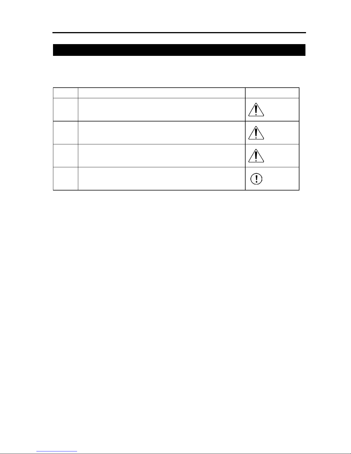
The safety precautions are divided into "Danger", "Warning", "Caution" and "Notice" according to
the warning level, as follows, and described in the Instruction Manual for each model.
Level Degree of risk to persons and property Symbol
Danger
This indicates an imminently hazardous situation which, if the product
is not handled correctly, will result in death or serious injury.
Danger
Warning
This indicates a potentially hazardous situation which, if the product
is not handled correctly, could result in death or serious injury.
Warning
Caution
This indicates a potentially hazardous situation which, if the product
is not handled correctly, may result in minor injury or property
damage.
Caution
Notice
This indicates a situation in which, while injury is not a likely result,
the precautions should be observed in order to use the product
appropriately.
Notice
Page 15

Precautions for Handling
Intro-9
Precautions for Handling
1. The Safety Guide attached with the product is intended to permit safe use of
the product and thus to prevent risks and property damage. Be sure to read it
before handling the product.
2. Do not attempt any handling or operation that is not indicated in this instruction
manual.
3. Make sure to secure the actuator properly in accordance with this instruction
manual.
If the actuator is not securely fixed, this may lead to abnormal noise, vibration, breakdown or
shortened product life.
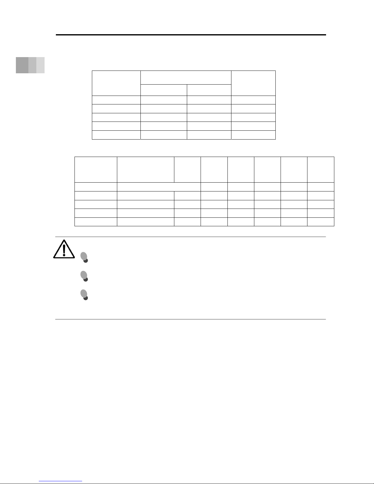
4. Make sure to observe the usage conditions and environment of the product.
Operation outside the warranty could cause decreased performance or product breakdown.
Use within the allowable range for each item.
Item
Cautions
for use
Problems or breakdowns which may
occur if the allowable
range is exceeded
Speed and
acceleration/deceleration
Use within the
allowable
range
May lead to abnormal noise, vibration,
breakdown, or shortened product life.
Allowable load moment
Use within the
allowable
range
May lead to abnormal noise, vibration,
breakdown, or shortened product life.
In extreme cases, flaking may occur on the
guide or ball screw.
Overhang load length
Mounting a load with an overhang length
greater than the allowable values may lead
to vibration or abnormal noise.
Page 16

Precautions for Handling
International Standard Compliance
Intro-10
5. If return operations are continued over a short distance, they may rapidly
degrade the film of grease.
Continuous return operation within a distance less than 30mm may cause the grease film to
degrade rapidly.
As a guideline, in every 5,000 to 10,000 cycles, have approximately 5 cycles of return operation
over a 50mm distance or more to regenerate the oil film. Continued use of the actuator in that
state may lead to breakdown.
In extreme cases, flaking may occur on the guide or ball screw.
6. Do not attempt to have sliders collide with an obstacle at high speed.
This may damage the coupling or other mechanical parts.
7. For Double Slider Specification (Option Code: W) in Reversed-home
Specification (Option Code: NM), make sure to have the home-return
operation conducted after joining the driver slider and free slider.
8. In some conditions of environment of use, postures of installation and
conditions of operation, the base oil separated from the grease may come out
of ROBO Cylinder.
It is recommended to have a protection in case the peripheral devices could
get influence of the base oil.
International Standard Compliance
The ROBO Cylinder complies with the following overseas standards.
Refer to the Overseas Standard Compliance Manual (ME0287) for more detailed information.
CE Marking RoHS Directive
{ {
Page 17

Names of the Parts
Intro-11
Names of the Parts
In this manual, the actuator left/right sides and motor/opposite sides are shown as in the figure
below.
Standard Type Motor Straight Type
Standard Type Motor Reversing Type
Rea
r
Bracke
t
Reverse Bracket
Opposite Side
of the Motor
Left Side
Motor Side
Sheet Retaine
r
Stainless Steel Shee
t
Moto
r
Cove
r
A
ctuato
r
Cable Assy
Tapped hole fo
r
Ground Line Attachment
Sheet Retainer
End Cove
r
Slider Cove
r
Slide
r
Coupling Cove
r
Motor Bracket
Pulley Cove
r
Front Bracket
Side Cover
Base
MotorUnit
Right Side
Page 18

Names of the Parts
Intro-12
Cleanroom Type Motor Straight Type
Page 19

Specifications
1.1 Checking the product ··············································· 1-1
Parts ······················································································ 1-1
How to Read the Model Nameplate ·············································· 1-2
How to Read the Model Number ·················································· 1-2
Product list ·············································································· 1-3
1.2 Specifications ························································· 1-4
Specifications ·········································································· 1-4
Double Slider (Option) ······························································· 1-28
Duty ratio ················································································ 1-29
1.3 Options ································································· 1-31
With brake (Model Code: B) ························································ 1-31
Cable Exit Direction Changed
(Model Code: CJT, CJR, CJL, CJB and CJO) ······························· 1-31
High Precision Specifications (Model Code: HPR) ··························· 1-31
Motor Reversed Direction (Model Code: ML, MR) ··························· 1-31
Reversed-home Specification (Model Code: NM) ···························· 1-31
Slider Roller Specification (Model Code: SR) ·································· 1-32
Vacuum Joint Attachment Opposite Type (Model Code: VR) ············· 1-32
Double Slider Specification (Model Code: W) ································· 1-32
Rear Attachment Plate (Model Code: RP) ······································ 1-32
Slider spacer (Model Code: SS) ··················································· 1-33
1.4 Accessories ··························································· 1-35
Motor Cable ············································································· 1-35
Encoder Cable ········································································· 1-36
ROBO Cylinder
Chapter
Page 20

1.1 Checking the Product
1-1
1. Specifications
1.1 Checking the Product
Parts
The following table shows the product configuration for the standard specification.
See the component list for the details of the enclosed components. If you find any fault or missing
parts, contact your local IAI distributor.
Body Accessories
Actuator Quantity 1 Motor Cable Quantity 1
Encoder Cable Quantity 1
Accessories
In-house Made Seals
Quantity 1
Cross Recessed Pan Head
Screw with Captive Washer M3×6
Quantity 2
For affixing ground cable
Cable Band Quantity 2
For clamping connector cover
* Refer to International
Application Manual (ME0287)
for how to use it.
Accessories (Documents/DVD)
First Step Guide
Quantity 1
Safety Guide Quantity 1
Instruction Manual (DVD)
Quantity 1
Page 21

1.1 Checking the Product
1-2
1. Specifications
How to Read the Model Nameplate
How to Read the Model Number
Model→
Serial number→
[Nameplate Position]
N
P
S
M
X□□
R□□
None
1m
3m
5m
Length Specification
Robot Cable
(Setting available in
every 50mm for pitch)
WA Battery-less Absolute
Applicable
Controller
Ball Screw
Lead
Encoder
Type
Motor
Wattage
Type Series
Stroke
WA
RCS4
SA4C
SA6C
SA7C
SA8C
SA4R
SA6R
SA7R
SA8R
Body Width 40mm
Coupling Type
B
CJT
CJR
CJL
CJO
CJB
HPR
ML
MR
NM
RP
SS
SR
W
With brake
Cable Exit Direction Changed (Top)
Cable Exit Direction Changed (Right)
Cable Exit Direction Changed (Left)
Cable Exit Direction Changed (Outward)
Cable Exit Direction Changed (Bottom)
High Precision Specifications
Motor Left Reversed Direction
Motor Right Reversed Direction
Reversed-home Specification
Rear Attachment Plate
Slider spacer
Slider Roller Specification
Double Slider Specification
60
100
200
400
60W
100W
200W
400W
* Please note that the available range of ball screw lead, stroke and options will differ depending on the actuator type.
T2
SCON
MSCON
SSEL
XSEL-P/Q
XSEL-RA/SA
Options
Cable Length
2.5
3
4
5
6
8
10
12
16
20
24
30
36
48
Lead 2.5mm
Lead 3mm
Lead 4mm
Lead 5mm
Lead 6mm
Lead 8mm
Lead 10mm
Lead 12mm
Lead 16mm
Lead 20mm
Lead 24mm
Lead 30mm
Lead 36mm
Lead 48mm
50
1100
50mm
1100mm
to
to
Body Width 60mm
Coupling Type
Body Width 70mm
Coupling Type
Body Width 90mm
Coupling Type
Body Width 40mm
Motor-Reversed Type
Body Width 60mm
Motor-Reversed Type
Body Width 70mm
Motor-Reversed Type
Body Width 90mm
Motor-Reversed Type
N
P
S
M
2.5
3
4
5
6
8
10
12
16
20
24
50
1100
WA
WARCS4CR
SA4C
SA6C
SA7C
SA8C
B
CJT
CJR
CJL
CJB
HPR
NM
VR
W
Vacuum Joint Attachment Opposite Type
60
100
200
400
T2
Applicable
Controller
Ball Screw
Lead
Encoder
Type
Motor
Wattage
Type Series
Stroke
Options
Cable Length
Body Width 40mm
Coupling Type
Body Width 60mm
Coupling Type
Body Width 70mm
Coupling Type
Body Width 90mm
Coupling Type
Battery-less Absolute
(Setting available in
every 50mm for pitch)
to
to
None
Length Specification
Robot Cable
With brake
Cable Exit Direction Changed (Top)
Cable Exit Direction Changed (Right)
Cable Exit Direction Changed (Left)
Cable Exit Direction Changed (Bottom)
High Precision Specifications
Reversed-home Specification
Double Slider Specification
Lead 2.5mm
Lead 3mm
Lead 4mm
Lead 5mm
Lead 6mm
Lead 8mm
Lead 10mm
Lead 12mm
Lead 16mm
Lead 20mm
Lead 24mm
SCON
MSCON
SSEL
XSEL-P/Q
XSEL-RA/SA
50mm
1100mm
* Please note that the available range of ball screw lead, stroke and options will differ depending on the actuator type.
60W
100W
200W
400W
1m
3m
5m
X□□
R□□
Page 22

1.1 Checking the Product
1-3
1. Specifications
Product list
Cleanroom Type
Max. Speed
(mm/s)
Category Type Appearance
Body Width
(mm)
Lead
(mm)
Motor Wattage
(W)
Positioning Repeatability
(mm)
Stroke
(mm)
Horizontal
Max. Payload (kg)
Vertical
16
10
5
2.5
30
20
12
6
3
36
24
16
8
4
48
30
20
10
5
16
10
5
2.5
30
20
12
6
3
36
24
16
8
4
48
30
20
10
5
960
600
300
150
1600
1200
720
360
180
1800
1500
1000
500
240
2200
1800
1200
600
300
960
600
300
150
1600
1200
720
360
180
1800
1500
1000
500
240
2100
1800
1200
600
300
53
85
170
340
57
85
142
283
566
95
142
214
427
855
141
226
339
678
1357
53
85
170
340
57
85
142
283
566
95
142
214
427
855
141
226
339
678
1357
10
14
17
20
11
18
30
45
45
7
30
40
45
50
8
30
60
80
90
10
14
17
20
11
18
30
45
45
7
30
38
45
50
8
30
60
80
90
3
5
8
12
3.5
6
11
15
15
4
7
12
20
25
-
12
20
35
45
2.5
4.5
8
12
3
5
9
15
15
4
6
12
18
25
-
12
20
35
45
±0.01
[±0.005]
±0.01
±0.01
±0.01
±0.01
±0.01
±0.01
±0.01
±0.01
±0.01
±0.01
60
100
200
400
60
100
200
400
50 to 500
(Every 50 st)
50 to 800
50 to 800
50 to 1100
50 to 500
50 to 800
50 to 800
50 to 1100
Values in brackets [ ] show specifications for high-precision type
40mm
60mm
70mm
90mm
40mm
60mm
70mm
90mm
Motor
Straight
Type
Motor
Reversing
Type
SA4C
SA6C
SA7C
SA8C
SA4R
SA6R
SA7R
SA8R
Rated Thrust
(N)
(Every 50 st)
(Every 50 st)
(Every 50 st)
(Every 50 st)
(Every 50 st)
(Every 50 st)
(Every 50 st)
[±0.005]
[±0.005]
[±0.005]
Values in brackets [ ] show specifications for high-precision type
16
10
5
2.5
20
12
6
3
24
16
8
4
20
10
5
1200
600
300
339
678
1357
60
80
90
20
35
45
3
5
8
12
18
30
45
45
30
40
45
50
6
11
15
15
7
12
20
25
10
14
17
20
1200
720
360
180
1500
1000
500
240
85
142
283
566
142
214
427
855
960
600
300
150
53
85
170
340
±0.01
60
100
200
400
50 to 500
50 to 800
50 to 800
50
to
1100
±0.01
±0.01
±0.01
±0.01
40mm
60mm
70mm
90mm
SA4C
SA6C
SA7C
SA8C
Cleanliness
Class 10
(Fed.Std.209D
Standards)
Class 2.5 Equivalent
(ISO14644-1
Standards)
Max. Speed
(mm/s)
Category Type Appearance
Body Width
(mm)
Lead
(mm)
Motor Wattage
(W)
Positioning Repeatability
(mm)
Stroke
(mm)
Horizontal
Max. Payload (kg)
Vertical
Rated
Thrust
(N)
[±0.005]
Motor
Straight
Type
[±0.005]
[±0.005]
[±0.005]
(Every 50 st)
(Every 50 st)
(Every 50 st)
(Every 50 st)
Page 23

1.2 Specifications
1-4
1. Specifications
1.2 Specifications
Specifications
[1] RCS4(CR)-SA4C
[Lead and Payload]
Lead
(mm)
Max. Payload
Rated Thrust
(N)
Horizontal(kg) Vertical(kg)
16 10 3 53
10 14 5 85
5 17 8 170
2.5 20 12 340
[Stroke and Max Speed]
Unit: mm/s
Lead
(mm)
50 to 450
(Every 50mm)
500
(mm)
16 960 875
10 600 555
5 300 275
2.5 150 135
Caution
The maximum speed may not be achieved when the stroke or movement distance is
short or when acceleration/deceleration is set low.
Setting at or below the minimum speed may lead to abnormal noise or unstable speeds.
Do not attempt to set below the minimum speed.
The minimum speed can be calculated with the equation below.
Minimum speed [mm/s] = ball screw lead [mm/r] ÷ 16384 [p/r] x 1000 [1/s]
(mm/r: movement per 1 motor revolution, p/r: pulse per 1 motor revolution)
Page 24

1.2 Specifications
1-5
1. Specifications
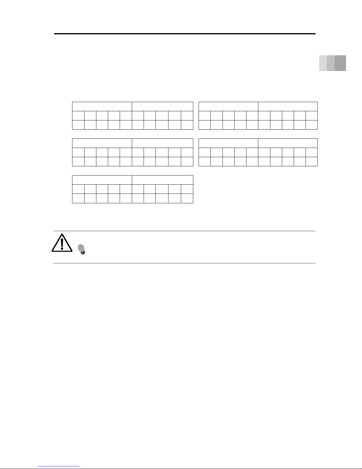
[Payload by Acceleration]
At low load capacity, the acceleration/deceleration can be increased.
Lead 16 Lead 10
Horizontal Vertical Horizontal Vertical
0.3 0.5 0.7 1.0 1.2 0.3 0.5 0.7 1.0 1.2 0.3 0.5 0.7 1.0 1.2 0.3 0.5 0.7 1.0 1.2
10 8 6 6 4 3 3 1.5 1.5 1 14 14 12 10 6 5 5 3 3 2
Lead 5 Lead 2.5
Horizontal Vertical Horizontal Vertical
0.3 0.5 0.7 1.0 1.2 0.3 0.5 0.7 1.0 1.2 0.3 0.5 0.7 1.0 1.2 0.3 0.5 0.7 1.0 1.2
17 17 15 15 ‒ 8 8 6 6 ‒ 20 20 20 ‒ ‒ 12 12 10 ‒ ‒
Caution
Do not attempt to configure settings for acceleration/deceleration above the specifications.
This may lead to vibration, breakdown, or shortened product life.
Page 25

1.2 Specifications
1-6
1. Specifications
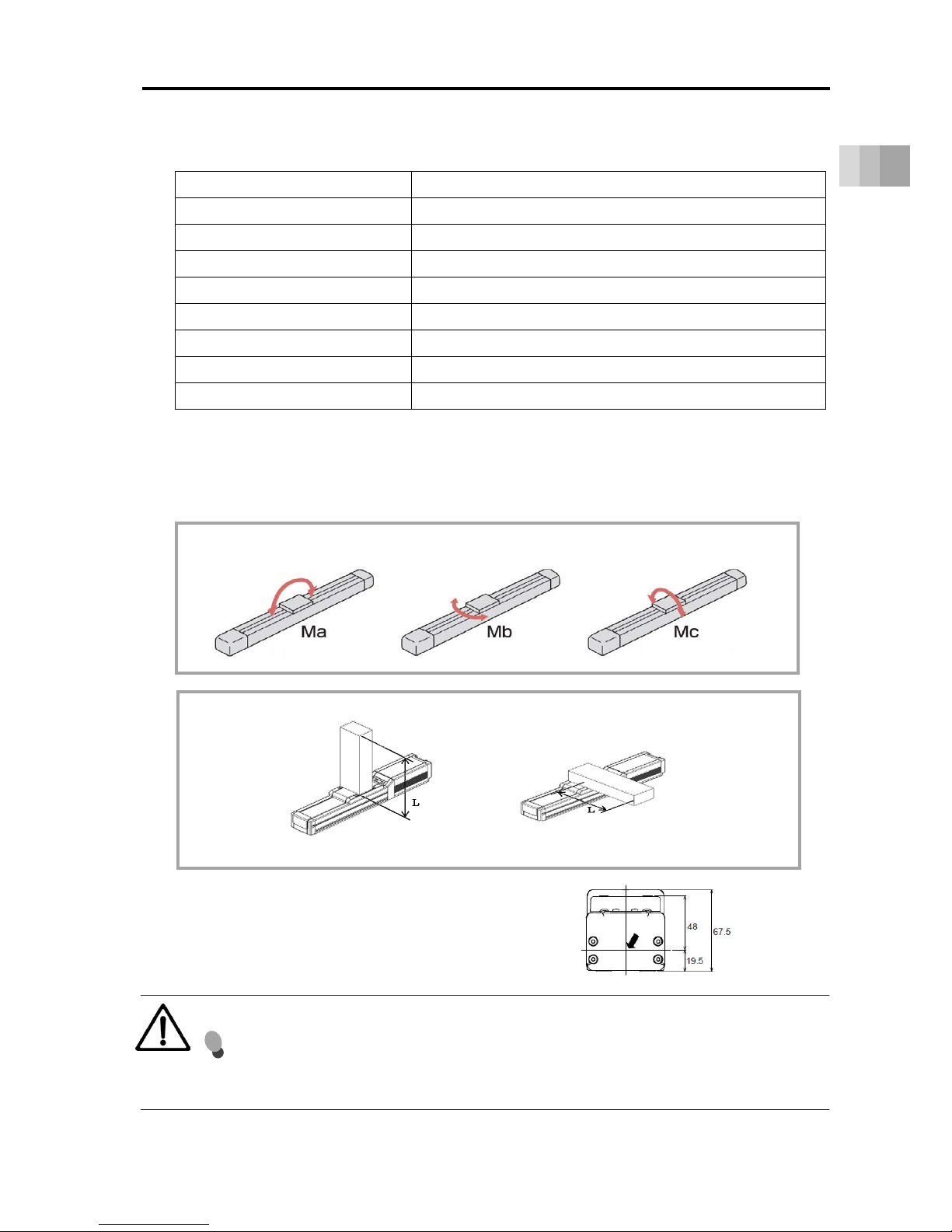
[Actuator Specifications]
Item Content
Drive System Ball Screw φ8mm, Rolled C10
Positioning Repeatability (*1) ±0.01mm [±0.005mm]
Lost Motion 0.1mm or less
Base Material: Aluminum, White Anodized
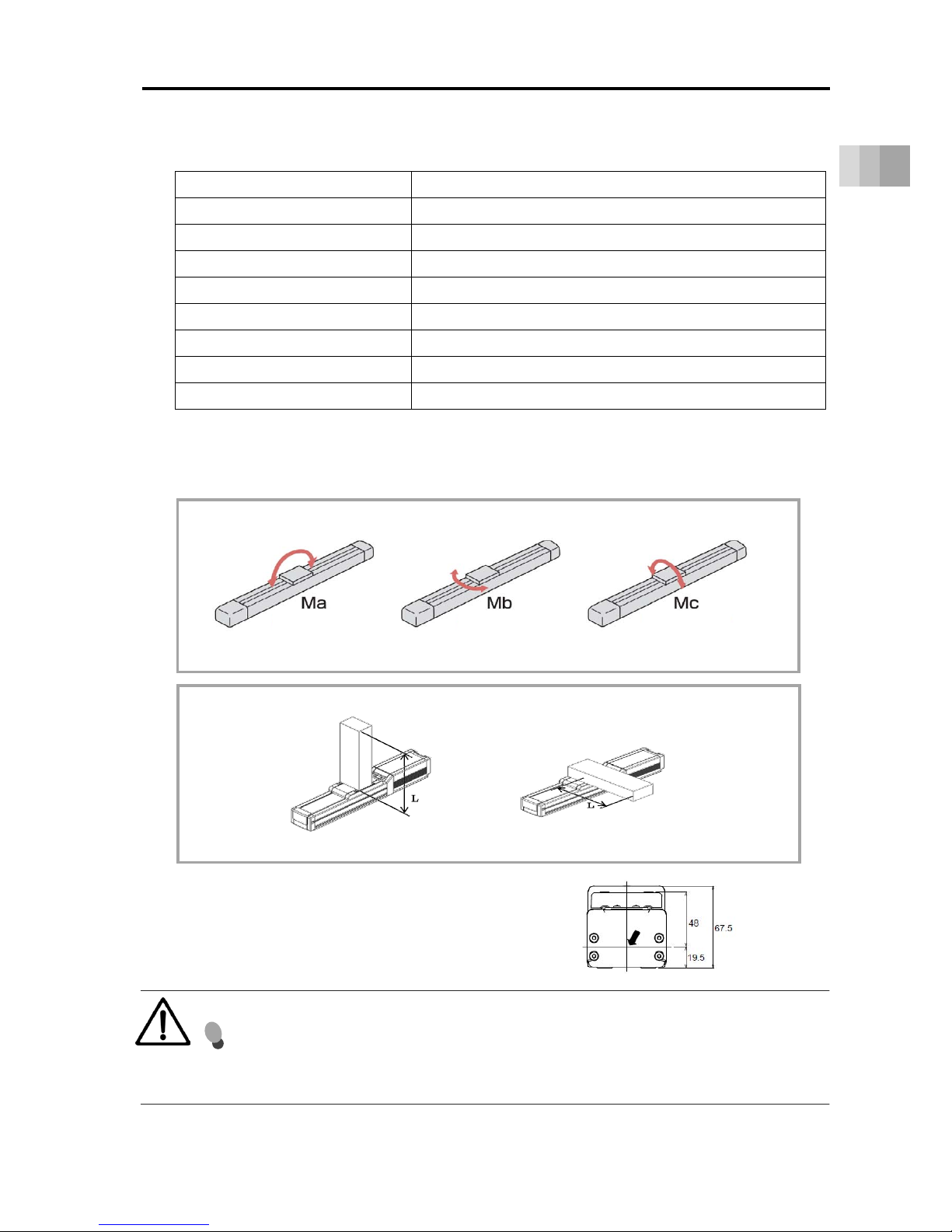
Allowable static moment Ma direction: 13.0 N•m, Mb direction: 18.6 N•m, Mc direction: 25.3 N•m
Allowable dynamic moment (*2) Ma direction: 5.0 N•m, Mb direction: 7.1 N•m, Mc direction: 9.7 N•m
No. of Encoder Pulses 16384
Ambient operating temperature/humidity 0 to 40°C, 85%RH or less (Non-condensing)
• Overhang load length guideline: 150mm or less
(*1) Number in brackets [ ] show the specification for high precision type.
(*2) For reference rated life of 5000km. The running life differs according to operation conditions and mounting
status.
Slider type moment direction
Slider type overhang load length (L = 150mm or less)
Ma direction Mb•Mc direction
* For calculation of Ma and Mc moments,
take the position pointed with an arrow as the datum.
Caution
If the actuator is used with excessive allowable moment and overhang load, it may not
only lead to abnormal noise and vibration but also significantly reduce the life of the
actuator.
(Pitching)
(Yawing) (Rolling)
Page 26

1.2 Specifications
1-7
1. Specifications
[2] RCS4(CR)-SA6C
* There is no Lead 30 prepared for Cleanroom Type RCS4CR-SA6C.
[Lead and Payload]
Lead
(mm)
Max. Payload
Rated Thrust
(N)
Horizontal(kg) Vertical(kg)
30 11 3.5 57
20 18 6 85
12 30 11 142
6 45 15 283
3 45 15 566
[Stroke and Max Speed] Unit: mm/s
Lead
(mm)
50 to 500
(Every 50mm)
550
(mm)
600
(mm)
650
(mm)
700
(mm)
750
(mm)
800
(mm)
30 1600 1450 1260 1100 970 860
20 1200 1130 970 840 735 650 575
12 720 620 535 460 405 355 315
6 360 305 265 230 200 175 155
3 180 150 130 115 100 85 75
Caution
The maximum speed may not be achieved when the stroke or movement
distance is short or when acceleration/deceleration is set low.
Setting at or below the minimum speed may lead to abnormal noise or unstable
speeds.
Do not attempt to set below the minimum speed.
The minimum speed can be calculated with the equation below.
Minimum speed [mm/s] = ball screw lead [mm/r] ÷ 16384 [p/r] x 1000 [1/s]
(mm/r: movement per 1 motor revolution, p/r: pulse per 1 motor revolution)
Page 27

1.2 Specifications
1-8
1. Specifications
[Payload by Acceleration]
At low load capacity, the acceleration/deceleration can be increased.
Lead30 Lead20
Horizontal Vertical Horizontal Vertical
0.3 0.5 0.7 1.0 1.2 0.3 0.5 0.7 1.0 1.2 0.3 0.5 0.7 1.0 1.2 0.3 0.5 0.7 1.0 1.2
11 6 6 4 3 3.5 2 2 1.51.5 18 15 10 8 6 6 5 4 4 2
Lead12 Lead6
Horizontal Vertical Horizontal Vertical
0.3 0.5 0.7 1.0 1.2 0.3 0.5 0.7 1.0 1.2 0.3 0.5 0.7 1.0 1.2 0.3 0.5 0.7 1.0 1.2
30 24 20 15 15 11 10 10 8 8 45 30 20 20 ‒ 15 15 15 15 ‒
Lead3
Horizontal Vertical
0.3 0.5 0.7 1.0 1.2 0.3 0.5 0.7 1.0 1.2
45 30 20 ‒ ‒ 15 14 10 ‒ ‒
Caution
Do not attempt to configure settings for acceleration/deceleration above the specifications.
This may lead to vibration, breakdown, or shortened product life.
Page 28

1.2 Specifications
1-9
1. Specifications
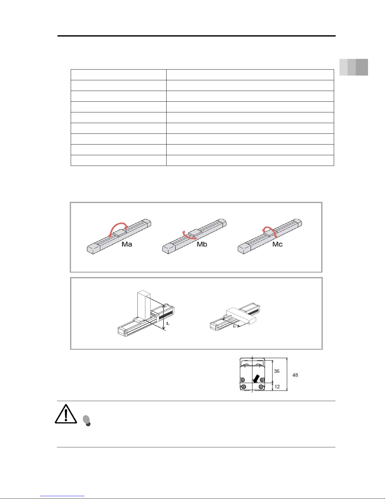
[Actuator Specifications]
Item Content
Drive System Ball Screw φ 10mm, Rolled C10
Positioning Repeatability (*1) ±0.01mm [±0.005mm]
Lost Motion 0.1mm or less
Base Material: Aluminum White Anodized
Allowable static moment Ma direction: 48.5 N•m, Mb direction: 69.3 N•m, Mc direction: 103 N•m
Allowable dynamic moment (*2) Ma direction: 11.6 N•m, Mb direction: 16.6 N•m, Mc direction: 24.6 N•m
No. of Encoder Pulses 16384
Ambient operating temperature/humidity 0 to 40°C, 85%RH or less (Non-condensing)
• Overhang load length guideline: 220mm or less
(*1) Number in brackets [ ] show the specification for high precision type.
(*2) For reference rated life of 5000km. The running life differs according to operation conditions and mounting
status.
Slider type moment direction
Slider type overhang load length (L = 220mm or less)
Ma direction Mb•Mc direction
* For calculation of Ma and Mc moments,
take the position pointed with an arrow as the datum.
Caution
If the actuator is used with excessive allowable moment and overhang load, it
may not only lead to abnormal noise and vibration but also significantly reduce
the life of the actuator.
(Pitching) (Yawing) (Rolling)
Page 29

1.2 Specifications
1-10
1. Specifications
[3] RCS4(CR)-SA7C
* There is no Lead 36 prepared for Cleanroom Type RCS4CR-SA7C.
[Lead and Payload]
Lead
(mm)
Max. Payload
Rated Thrust
(N)
Horizontal(kg) Vertical(kg)
36 7 4 95
24 30 7 142
16 40 12 214
8 45 20 427
4 50 25 855
[Stroke and Max Speed]
Unit: mm/s
Lead
(mm)
50 to 500
(Every 50mm)
550
(mm)
600
(mm)
650
(mm)
700
(mm)
750
(mm)
800
(mm)
36 1800 1620 1420 1260 1120
24 1500 1440 1240 1095 965 850 760
16 1000 965 830 720 635 560 500
8 500 475 410 355 315 275 245
4 240 235 205 175 155 135 120
Caution
The maximum speed may not be achieved when the stroke or movement
distance is short or when acceleration/deceleration is set low.
Setting at or below the minimum speed may lead to abnormal noise or unstable speeds.
Do not attempt to set below the minimum speed.
The minimum speed can be calculated with the equation below.
Minimum speed [mm/s] = ball screw lead [mm/r] ÷ 16384 [p/r] x 1000 [1/s]
(mm/r: movement per 1 motor revolution, p/r: pulse per 1 motor revolution)
Page 30

1.2 Specifications
1-11
1. Specifications
[Payload by Acceleration]
At low load capacity, the acceleration/deceleration can be increased.
Lead 36 Lead 24
Horizontal Vertical Horizontal Vertical
0.3 0.5 0.7 1.0 1.2 0.3 0.5 0.7 1.0 1.2 0.3 0.5 0.7 1.0 1.2 0.3 0.5 0.7 1.0 1.2
7 7 6 4 3 4 4 3 2 2 30 12 10 6 5 7 7 6 5 4
Lead 16 Lead 8
Horizontal Vertical Horizontal Vertical
0.3 0.5 0.7 1.0 1.2 0.3 0.5 0.7 1.0 1.2 0.3 0.5 0.7 1.0 1.2 0.3 0.5 0.7 1.0 1.2
40 30 15 15 12 12 12 10 8 8 45 40 40 35 ‒ 20 20 20 18 ‒
Lead 4
Horizontal Vertical
0.3 0.5 0.7 1.0 1.2 0.3 0.5 0.7 1.0 1.2
50 50 40 ‒ ‒ 25 25 20 ‒ ‒
Caution
Do not attempt to configure settings for acceleration/deceleration above the specifications.
This may lead to vibration, breakdown, or shortened product life.
Page 31
1.2 Specifications
1-12
1. Specifications
[Actuator Specifications]
Item Content
Drive System Ball Screw φ12mm, Rolled C10
Positioning Repeatability (*1) ±0.01mm[±0.005mm]
Lost Motion 0.1 mm or less
Base Material: Aluminum, White Anodized
Allowable static moment Ma direction:115 N•m,Mb direction:115 N•m,Mc direction:229 N•m
Allowable dynamic moment (*2) Ma direction:44.7 N•m,Mb direction:44.7 N•m,Mc direction:89.1 N•m
No. of Encoder Pulses 16384
Ambient operating temperature/humidity 0 to 40°C, 85%RH or less (Non-condensing)
• Overhang load length guideline:300mm or less
(*1) Number in brackets [ ] show the specification for high precision type.
(*2) For reference rated life of 5000km. The running life differs according to operation conditions and mounting
status.
Slider type moment direction
Slider type overhang load length (L = 300mm or less)
Ma direction Mb•Mc direction
* For calculation of Ma and Mc moments,
take the position pointed with an arrow as the datum.
Caution
If the actuator is used with excessive allowable moment and overhang load, it may not
only lead to abnormal noise and vibration but also significantly reduce the life of the
actuator.
(Pitching) (Yawing) (Rolling)
Page 32

1.2 Specifications
1-13
1. Specifications
[4] RCS4(CR)-SA8C
* There is no Lead 30 and Lead 48 prepared for Cleanroom Type RCS4CR-SA8C.
[Lead and Payload]
Lead
(mm)
Max. Payload
Rated Thrust
(N)
Horizontal(kg) Vertical(kg)
48 8 ‒ 141
30 30 12 226
20 60 20 339
10 80 35 678
5 90 45 1357
[Stroke and Max Speed]
Unit: mm/s
Lead
(mm)
50 to 600
(Every
50mm)
650
(mm)
700
(mm)
750
(mm)
800
(mm)
850
(mm)
900
(mm)
950
(mm)
1000
(mm)
1050
(mm)
1100
(mm)
48 2200 2180 1950 1760 1590 1450 1320 1210 1110
30 1800 1640 1440 1280 1155 1040 940 855 780 715 660
20 1200 1090 960 860 770 695 630 570 520 480 440
10 600 540 480 430 385 345 310 285 260 235 220
5 300 270 240 215 190 175 155 140 130 120 110
Caution
The maximum speed may not be achieved when the stroke or movement
distance is short or when acceleration/deceleration is set low.
Setting at or below the minimum speed may lead to abnormal noise or unstable speeds.
Do not attempt to set below the minimum speed.
The minimum speed can be calculated with the equation below.
Minimum speed [mm/s] = ball screw lead [mm/r] ÷ 16384 [p/r] x 1000 [1/s]
(mm/r: movement per 1 motor revolution, p/r: pulse per 1 motor revolution)
Page 33
1.2 Specifications
1-14
1. Specifications
[Payload by Acceleration]
At low load capacity, the acceleration/deceleration can be increased.
Lead 48 Lead 30
Horizontal Vertical Horizontal Vertical
0.3 0.5 0.7 1.0 1.2 0.3 0.5 0.7 1.0 1.2 0.3 0.5 0.7 1.0 1.2 0.3 0.5 0.7 1.0 1.2
8 8 8 5 4 ‒ ‒ ‒ ‒ ‒ 30 25 20 15 10 12 12 10 8 6
Lead 20 Lead 10
Horizontal Vertical Horizontal Vertical
0.3 0.5 0.7 1.0 1.2 0.3 0.5 0.7 1.0 1.2 0.3 0.5 0.7 1.0 1.2 0.3 0.5 0.7 1.0 1.2
60 40 30 20 15 20 20 18 15 12 80 80 70 60 ‒ 35 35 35 30 ‒
Lead 5
Horizontal Vertical
0.3 0.5 0.7 1.0 1.2 0.3 0.5 0.7 1.0 1.2
90 90 70 ‒ ‒ 45 45 35 ‒ ‒
Caution
Do not attempt to configure settings for acceleration/deceleration above the specifications.
This may lead to vibration, breakdown, or shortened product life.
Page 34

1.2 Specifications
1-15
1. Specifications
[Actuator Specifications]
Item Content
Drive System Ball Screw φ16mm, Rolled C10
Positioning Repeatability (*1) ±0.01mm[±0.005mm]
Lost Motion 0.1mm or less
Base Material: Aluminum, White Anodized
Allowable static moment Ma direction:219 N•m, Mb direction:219 N•m, Mc direction:414 N•m
Allowable dynamic moment (*2) Ma direction:77.0 N•m, Mb direction:77.0 N•m, Mc direction:146 N•m
No. of Encoder Pulses 16384
Ambient operating temperature/humidity 0 to 40°C, 85%RH or less (Non-condensing)
• Overhang load length guideline:400mm or less
(*1) Number in brackets [ ] show the specification for high precision type.
(*2) For reference rated life of 5000km. The running life differs according to operation conditions and mounting
status.
Slider type moment direction
Slider type overhang load length (L = 400mm or less)
Ma direction Mb•Mc direction
*For calculation of Ma and Mc moments,
take the position pointed with an arrow as the datum.
Caution
If the actuator is used with excessive allowable moment and overhang load, it may not
only lead to abnormal noise and vibration but also significantly reduce the life of the
actuator.
(Pitching)
(Yawing) (Rolling)
Page 35

1.2 Specifications
1-16
1. Specifications
[5] RCS4-SA4R
[Lead and Payload]
Lead
(mm)
Max. Payload
Rated Thrust
(N)
Horizontal(kg) Vertical(kg)
16 10 2.5 53
10 14 4.5 85
5 17 8 170
2.5 20 12 340
[Stroke and Max Speed]
Unit: mm/s
Lead
(mm)
50 to 450
(Every 50mm)
500
(mm)
16 960 875
10 600 555
5 300 275
2.5 150 135
Caution
The maximum speed may not be achieved when the stroke or movement distance is
short or when acceleration/deceleration is set low.
Setting at or below the minimum speed may lead to abnormal noise or unstable speeds.
Do not attempt to set below the minimum speed.
The minimum speed can be calculated with the equation below.
Minimum speed [mm/s] = ball screw lead [mm/r] ÷ 16384 [p/r] x 1000 [1/s]
(mm/r: movement per 1 motor revolution, p/r: pulse per 1 motor revolution)
Page 36

1.2 Specifications
1-17
1. Specifications
[Payload by Acceleration]
At low load capacity, the acceleration/deceleration can be increased.
Lead 16 Lead 10
Horizontal Vertical Horizontal Vertical
0.3 0.5 0.7 1.0 1.2 0.3 0.5 0.7 1.0 1.2 0.3 0.5 0.7 1.0 1.2 0.3 0.5 0.7 1.0 1.2
10 8 6 6 ‒ 2.5 2.5 1.5 1.5 ‒ 14 14 12 10 ‒ 4.5 4.5 3 3 ‒
Lead 5 Lead 2.5
Horizontal Vertical Horizontal Vertical
0.3 0.5 0.7 1.0 1.2 0.3 0.5 0.7 1.0 1.2 0.3 0.5 0.7 1.0 1.2 0.3 0.5 0.7 1.0 1.2
17 17 15 13 ‒ 8 8 6 6 ‒ 20 20 20 ‒ ‒ 12 12 10 ‒ ‒
Caution
Do not attempt to configure settings for acceleration/deceleration above the specifications.
This may lead to vibration, breakdown, or shortened product life.
Page 37
1.2 Specifications
1-18
1. Specifications
[Actuator Specifications]
Item Content
Drive System Ball Screw φ8mm, Rolled C10
Positioning Repeatability (*1) ±0.01mm[±0.005mm]
Lost Motion 0.1mm or less
Base Material: Aluminum, White Anodized
Allowable static moment Ma direction: 13.0 N•m, Mb direction: 18.6 N•m, Mc direction: 25.3 N•m
Allowable dynamic moment (*2) Ma direction: 5.0 N•m, Mb direction: 7.1 N•m, Mc direction: 9.7 N•m
No. of Encoder Pulses 16384
Ambient operating temperature/humidity 0 to 40°C, 85%RH or less (Non-condensing)
• Overhang load length guideline:150mm or less
(*1) Number in brackets [ ] show the specification for high precision type.
(*2) For reference rated life of 5000km. The running life differs according to operation conditions and mounting
status.
Slider type moment direction
Slider type overhang load length (L = 150mm or less)
Ma direction Mb•Mc direction
* For calculation of Ma and Mc moments,
take the position pointed with an arrow as the datum.
Caution
If the actuator is used with excessive allowable moment and overhang load, it may not
only lead to abnormal noise and vibration but also significantly reduce the life of the
actuator.
(Pitching)
(Yawing) (Rolling)
Page 38
1.2 Specifications
1-19
1. Specifications
[6] RCS4-SA6R
[Lead and Payload]
Lead
(mm)
Max. Payload
Rated Thrust
(N)
Horizontal(kg) Vertical(kg)
30 11 3 57
20 18 5 85
12 30 9 142
6 45 15 283
3 45 15 566
[Stroke and Max Speed]
Unit: mm/s
Lead
(mm)
50 to 500
(Every 50mm)
550
(mm)
600
(mm)
650
(mm)
700
(mm)
750
(mm)
800
(mm)
30 1600 1450 1260 1100 970 860
20 1200 1130 970 840 735 650 575
12 720 620 535 460 405 355 315
6 360 305 265 230 200 175 155
3 180 150 130 115 100 85 75
Caution
The maximum speed may not be achieved when the stroke or movement distance is
short or when acceleration/deceleration is set low.
Setting at or below the minimum speed may lead to abnormal noise or unstable speeds.
Do not attempt to set below the minimum speed.
The minimum speed can be calculated with the equation below.
Minimum speed [mm/s] = ball screw lead [mm/r] ÷ 16384 [p/r] x 1000 [1/s]
(mm/r: movement per 1 motor revolution, p/r: pulse per 1 motor revolution)
Page 39

1.2 Specifications
1-20
1. Specifications
[Payload by Acceleration]
At low load capacity, the acceleration/deceleration can be increased.
Lead 30 Lead 20
Horizontal Vertical Horizontal Vertical
0.3 0.5 0.7 1.0 1.2 0.3 0.5 0.7 1.0 1.2 0.3 0.5 0.7 1.0 1.2 0.3 0.5 0.7 1.0 1.2
11 6 6 4 ‒ 3 2 2 1.5‒ 18 15 10 8 ‒ 5 5 4 4 ‒
Lead 12 Lead 6
Horizontal Vertical Horizontal Vertical
0.3 0.5 0.7 1.0 1.2 0.3 0.5 0.7 1.0 1.2 0.3 0.5 0.7 1.0 1.2 0.3 0.5 0.7 1.0 1.2
30 24 20 15 ‒ 9 9 9 8 ‒ 45 30 20 20 ‒ 15 15 15 15 ‒
Lead 3
Horizontal Vertical
0.3 0.5 0.7 1.0 1.2 0.3 0.5 0.7 1.0 1.2
45 30 20 ‒ ‒ 15 14 10 ‒ ‒
Caution
Do not attempt to configure settings for acceleration/deceleration above the specifications.
This may lead to vibration, breakdown, or shortened product life.
Page 40

1.2 Specifications
1-21
1. Specifications
[Actuator Specifications]
Item Content
Drive System Ball Screw φ10mm, Rolled C10
Positioning Repeatability (*1) ±0.01mm[±0.005mm]
Lost Motion 0.1 mm or less
Base Material: Aluminum, White Anodized
Allowable static moment Ma direction: 48.5 N•m, Mb direction: 69.3 N•m, Mc direction: 103 N•m
Allowable dynamic moment (*2) Ma direction: 11.6 N•m, Mb direction: 16.6 N•m, Mc direction: 24.6 N•m
No. of Encoder Pulses 16384
Ambient operating temperature/humidity 0 to 40°C, 85%RH or less (Non-condensing)
• Overhang load length guideline:220mm or less
(*1) Number in brackets [ ] show the specification for high precision type.
(*2) For reference rated life of 5000km. The running life differs according to operation conditions and mounting
status.
Slider type moment direction
Slider type overhang load length (L = 220mm or less)
Ma direction Mb•Mc direction
* For calculation of Ma and Mc moments,
take the position pointed with an arrow as the datum.
Caution
If the actuator is used with excessive allowable moment and overhang load, it may not
only lead to abnormal noise and vibration but also significantly reduce the life of the
actuator.
(Pitching)
(Yawing) (Rolling)
Page 41

1.2 Specifications
1-22
1. Specifications
[7] RCS4-SA7R
[Lead and Payload]
Lead
(mm)
Max. Payload
Rated Thrust
(N)
Horizontal(kg) Vertical(kg)
36 7 4 95
24 30 6 142
16 38 12 214
8 45 18 427
4 50 25 855
[Stroke and Max Speed] Unit: mm/s
Lead
(mm)
50 to 500
(Every 50mm)
550
(mm)
600
(mm)
650
(mm)
700
(mm)
750
(mm)
800
(mm)
36 1800 1620 1420 1260 1120
24 1500 1440 1240 1095 965 850 760
16 1000 965 830 720 635 560 500
8 500 475 410 355 315 275 245
4 240 235 205 175 155 135 120
Caution
The maximum speed may not be achieved when the stroke or movement distance is
short or when acceleration/deceleration is set low.
Setting at or below the minimum speed may lead to abnormal noise or unstable speeds.
Do not attempt to set below the minimum speed.
The minimum speed can be calculated with the equation below.
Minimum speed [mm/s] = ball screw lead [mm/r] ÷ 16384 [p/r] x 1000 [1/s]
(mm/r: movement per 1 motor revolution, p/r: pulse per 1 motor revolution)
Page 42

1.2 Specifications
1-23
1. Specifications
[Payload by Acceleration]
At low load capacity, the acceleration/deceleration can be increased.
Lead 36 Lead 24
Horizontal Vertical Horizontal Vertical
0.3 0.5 0.7 1.0 1.2 0.3 0.5 0.7 1.0 1.2 0.3 0.5 0.7 1.0 1.2 0.3 0.5 0.7 1.0 1.2
7 7 6 4 ‒ 4 4 3 2 ‒ 30 12 10 6 ‒ 6 6 5 5 ‒
Lead 16 Lead 8
Horizontal Vertical Horizontal Vertical
0.3 0.5 0.7 1.0 1.2 0.3 0.5 0.7 1.0 1.2 0.3 0.5 0.7 1.0 1.2 0.3 0.5 0.7 1.0 1.2
38 30 15 15 ‒ 12 12 10 8 ‒ 45 40 40 35 ‒ 18 18 18 16 ‒
Lead 4
Horizontal Vertical
0.3 0.5 0.7 1.0 1.2 0.3 0.5 0.7 1.0 1.2
50 50 40 ‒ ‒ 25 25 20 ‒ ‒
Caution
Do not attempt to configure settings for acceleration/deceleration above the specifications.
This may lead to vibration, breakdown, or shortened product life.
Page 43
1.2 Specifications
1-24
1. Specifications
[Actuator Specifications]
Item Content
Drive System Ball Screw φ12mm, Rolled C10
Positioning Repeatability (*1) ±0.01mm[±0.005mm]
Lost Motion 0.1mm or less
Base Material: Aluminum, White Anodized
Allowable static moment Ma direction:115 N•m, Mb direction:115 N•m, Mc direction:229 N•m
Allowable dynamic moment (*2) Ma direction:44.7 N•m, Mb direction:44.7 N•m, Mc direction:89.1 N•m
No. of Encoder Pulses 16384
Ambient operating temperature/humidity 0 to 40°C 85%RH or less (Non-condensing)
• Overhang load length guideline:300mm or less
(*1) Number in brackets [ ] show the specification for high precision type.
(*2) For reference rated life of 5000km. The running life differs according to operation conditions and mounting
status.
Slider type moment direction
Slider type overhang load length (L = 300mm or less)
Ma direction Mb•Mc direction
* For calculation of Ma and Mc moments,
take the position pointed with an arrow as the datum.
Caution
If the actuator is used with excessive allowable moment and overhang load, it may not
only lead to abnormal noise and vibration but also significantly reduce the life of the
actuator.
(Pitching)
(Yawing) (Rolling)
Page 44

1.2 Specifications
1-25
1. Specifications
[8] RCS4-SA8R
[Lead and Payload]
Lead
(mm)
Max. Payload
Rated Thrust
(N)
Horizontal(kg) Horizontal(kg)
48 8 - 141
30 30 12 226
20 60 20 339
10 80 35 678
5 90 45 1357
[Stroke and Max Speed]
Unit: mm/s
Lead
(mm)
50 to 600
(Every
50mm)
650
(mm)
700
(mm)
750
(mm)
800
(mm)
850
(mm)
900
(mm)
950
(mm)
1000
(mm)
1050
(mm)
1100
(mm)
48 2100 1950 1760 1590 1450 1320 1210 1110
30 1800 1640 1440 1280 1155 1040 940 855 780 715 660
20 1200 1090 960 860 770 695 630 570 520 480 440
10 600 540 480 430 385 345 310 285 260 235 220
5 300 270 240 215 190 175 155 140 130 120 110
Caution
The maximum speed may not be achieved when the stroke or movement distance is
short or when acceleration/deceleration is set low.
Setting at or below the minimum speed may lead to abnormal noise or unstable speeds.
Do not attempt to set below the minimum speed.
The minimum speed can be calculated with the equation below.
Minimum speed [mm/s] = ball screw lead [mm/r] ÷ 16384 [p/r] x 1000 [1/s]
(mm/r: movement per 1 motor revolution, p/r: pulse per 1 motor revolution)
Page 45

1.2 Specifications
1-26
1. Specifications
[Payload by Acceleration]
At low load capacity, the acceleration/deceleration can be increased.
Lead 48 Lead 30
Horizontal Vertical Horizontal Vertical
0.3 0.5 0.7 1.0 1.2 0.3 0.5 0.7 1.0 1.2 0.3 0.5 0.7 1.0 1.2 0.3 0.5 0.7 1.0 1.2
8 8 8 5 ‒ ‒ ‒ ‒ ‒ ‒ 30 25 20 15 ‒ 12 12 10 8 ‒
Lead 20 Lead 10
Horizontal Vertical Horizontal Vertical
0.3 0.5 0.7 1.0 1.2 0.3 0.5 0.7 1.0 1.2 0.3 0.5 0.7 1.0 1.2 0.3 0.5 0.7 1.0 1.2
60 40 30 20 ‒ 20 20 18 15 ‒ 80 80 70 60 ‒ 35 35 35 30 ‒
Lead 5
Horizontal Vertical
0.3 0.5 0.7 1.0 1.2 0.3 0.5 0.7 1.0 1.2
90 90 70 ‒ ‒ 45 45 35 ‒ ‒
Caution
Do not attempt to configure settings for acceleration/deceleration above the specifications.
This may lead to vibration, breakdown, or shortened product life.
Page 46

1.2 Specifications
1-27
1. Specifications
[Actuator Specifications]
Item Content
Drive System
Ball Screw
φ
16mm, Rolled C10
Positioning Repeatability (*1) ±0.01mm[±0.005mm]
Lost Motion 0.1mm or less
Base Material: Aluminum, White Anodized
Allowable static moment Ma direction: 219 N•m, Mb direction: 219 N•m, Mc direction: 414 N•m
Allowable dynamic moment (*2) Ma direction: 77.0 N•m, Mb direction: 77.0 N•m, Mc direction: 146 N•m
No. of Encoder Pulses 16384
Ambient operating temperature/humidity 0 to 40°C, 85%RH or less (Non-condensing)
• Overhang load length guideline:400mm or less
(*1) Number in brackets [ ] show the specification for high precision type.
(*2) For reference rated life of 5000km. The running life differs according to operation conditions and mounting
status.
Slider type moment direction
Slider type overhang load length (L = 400mm or less)
Ma direction Mb•Mc direction
* For calculation of Ma and Mc moments,
take the position pointed with an arrow as the datum.
Caution
If the actuator is used with excessive allowable moment and overhang load, it may not
only lead to abnormal noise and vibration but also significantly reduce the life of the
actuator.
(Pitching)
(Yawing) (Rolling)
Page 47

1.2 Specifications
1-28
1. Specifications
Double Slider (Option)
[Table for Double Slider Type]
Name
of Type
Allowable dynamic moment Allowable static moment
Overhang
load
length
(mm)
Slider
Mass
(kg)
Slider
length
(mm)
Min.
Effective
Stroke
for
Double
Slider
(mm)
Standard
rated life
(km)
Slider Span (mm)
Ma
direction
(N•m)
Mb
direction
(N•m)
Mc
direction
(N•m)
Ma
direction
(N•m)
Mb
direction
(N•m)
Mc
direction
(N•m)
Ma
direction
Mb•Mc
direction
Actual
Slider
Span
Slider
Cover
Span
SA4 5000 60 24 44.6 63.6 15.7 143 204 50.5 420 1 76 50
SA6 5000 90 40 106 152 40 546 779 205 630 2 110 50
SA7 5000 70 20 285 285 145 900 900 458 810 2 130 50
SA8 5000 120 35 565 565 237 1980 1980 828 1200 2.5 165 50
【Figure of Double Slider】
Caution
If double slider (option) is ordered, consider the available stroke should be the value that
the length of slider and slider cover span are subtracted from the stroke shown in the
model code. Therefore, add the following number to the necessary stroke when indicate
the stroke at order. Also, make sure that the “necessary stroke” should be the minimum
effective stroke of the double slider type or above.
Stroke Length to Order (Nominal Stroke)
“Necessary Stroke” + “Slider Cover Span” + “Slider Length” or more
The payload of the double slider should consider the weight of the slider itself subtracted
from the performance in the specification for the maximum.
When you consider the maximum velocity, consider the stroke length to order (nominal
stroke) as the value of stroke in [Stroke and Max Speed].
Slider length
Slider Cover Span
Actual Slider Span
Page 48

1.2 Specifications
1-29
1. Specifications
Duty ratio
The duty ratio is the operating rate,
shown in %, of the actuator operating
time within one cycle.
As the reference for duty available to use may differ depending on the operation conditions
(payload, acceleration / deceleration, etc.), it is necessary to figure out the load factor LF and
acceleration / deceleration time ratio t
od
using the calculation formulae below and find it out from
the graph.
1) Figure out the load factor LF using the calculation formulae below.
Maximum payload at the acceleration 0.3G is described in 1.2 Specifications.
2) Figure out the acceleration / deceleration time ratio tod using the calculation formulae
below.
Acceleration / Deceleration Time Ratio tod =
Acceleration Time during Operation + Deceleration Time during Operation
Duration of Operation
[%]
Acceleration Time =
Velocity during Operation [mm/s]
Acceleration during Operation [mm/s
2
] [sec]
Acceleration [mm/s
2
] = Acceleration [G] × 9,800mm/s2
Deceleration Time =
Velocity during Operation [mm/s]
Deceleration during Operation [mm/s
2
] [sec]
Deceleration [mm/s
2
] = Deceleration [G] × 9,800mm/s
2
[When indicated acceleration / deceleration is at
acceleration / deceleration 0.3G or below]
Load Factor: LF =
M×α
M
r
×0.3
[%]
Max. Payload at Acceleration 0.3G
: Mr [kg]
Acceleration / Deceleration 0.3G : 0.3 [G]
Payload during Operation : M [kg]
Acceleration during Operation : α [G]
[When indicated acceleration / deceleration is at
acceleration / deceleration 0.3G or above]
Load Factor: LF =
M×α
M
d
×α
=
M
M
d
[%]
Payload at Indicated Acceleration : M
d
[kg]
Payload during Operation : M [kg]
Acceleration during Operation : α [G]
Page 49

1.2 Specifications
1-30
1. Specifications
3) Read a reference for duty with the figured out “Load Factor” and “Acceleration /
Deceleration Time Ratio”.
e.g.) The reference for duty when the load factor LF is 80% and the acceleration / deceleration time
ratio t
od
is 80% should be approximately 75%.
0
20
40
60
80
100
0 20406080100
加減速度時間比率 tod〔%〕
デュ
ーティー
の目安〔%〕
LF
=60%
LF
= 50%
未満
約75%
LF
LF
LF
LF
= 70%
= 80%
= 90%
=100%
負荷率〔%〕
Reference for Duty [%]
Acceleration / Deceleration Time Ratio tod [%]
LF = Below 50%
Load Factor [%]
Approximately 75%
Page 50

1.3 Options
1-31
1. Specifications
1.3 Options
With brake (Model Code: B)
This is used to prevent the slider from moving during power outages or when the servo is OFF.
It can also be used to prevent the slider from falling when mounted vertically.
Cable Exit Direction Changed (Model Code: CJT, CJR, CJL, CJB and CJO)
The orientation of the motor / encoder cable to be installed on the actuator unit can be changed to
top/bottom/right/left.
High Precision Specifications (Model Code: HPR)
Standard positioning repeatability is ± 0.01mm. When this option is specified, positioning
repeatability will become ± 0.005mm. It should be available to order only for lead length 20mm or
less.
Motor Reversed Direction (Model Code: ML, MR)
It is the code to indicate the direction of motor reversed when selecting the motor reversed type.
ML shows reversed to left and MR to right.
Reversed-home Specification (Model Code: NM)
The standard home position is on the motor side.
However, the opposite side specification is selected if the home position direction is reversed in
accordance with equipment layout or assembly direction.
CJT
Top Side
Figure viewed
from motor side
CJB
Bottom Side
CJL
Left Side
CJR
Right Side
Motor Straight Type
Motor Reversing Type
CJT
Top Side
CJB
Bottom Side
CJO
Out Side
R
(RIGHT)
L
(LEFT)
Actuator
Page 51

1.3 Options
1-32
1. Specifications
Slider Roller Specification (Model Code: SR)
The structure of the slider in the standard type can be changed to the roller structure same as the
one in the cleanroom type.
If it gets chosen to have the slider roller type, the appearance and dimensions of the slider cover
should become the same as the cleanroom type.
Vacuum Joint Attachment Opposite Type (Model Code: VR)
The vacuum joint should be attached on the left of the main unit in the view from the motor end in
standard, which can be changed to the right (opposite) in option.
Double Slider Specification (Model Code: W)
This is an option that adds a free slider that is not connected to the ball screw.
Doubling the slider makes it possible to increase the moment and the overhang load length.
* Refer to" Double Slider (Option) (Page 1-28)" in "1.2 Specifications" for details.
Rear Attachment Plate (Model Code: RP)
It is a bracket (plate) to affix the motor reversed type (SA4R) at the back to a device.
Page 52

1.3 Options
1-33
1. Specifications
Slider spacer (Model Code: SS)
It is a spacer to set the top of the slider higher than the top of the motor cover.
2-φ3 H7 0 Depth 5
50
(Slider Cover length)
35
76
20 (±0.02 between of φ3H7)
65
+0. 01 0
Through 4-M3
(Bolt screwing Depth 7mm)
8
(56)
48
(5)
SA4R
Model number of single product: RCS4-SS-SA4
(77.5)
67.5 10
(8)
60
85
105
130
39 (±0.02 between of φ5H7)
(Slider Cover length)
2-φ5 H7 0 Depth 8
+0. 012
Through 4-M5
(Bolt screwing Depth 9mm)
SA7R
Model number of single product: RCS4-SS-SA7
Page 53

1.3 Options
1-34
1. Specifications
14
(81.5)
67.5
(10.5)
85
130
63
100
165
Through 4-M8
(Bolt screwing Depth 13mm)
(Slider Cover length)
2-φ6 H7 Depth 5
(±0.02 between of φ6H7)
SA8R
Model number of single product: RCS4-SS-SA8
Page 54
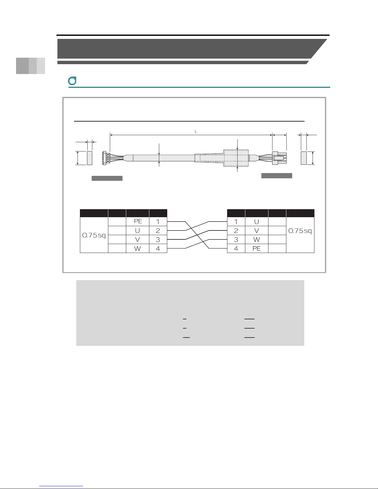
1.4 Accessories
1-35
1. Specifications
1.4 Accessories
Motor Cable
● The cable length should be 1m at minimum and 20m at maximum.
Order can be make in unit of 1m long.
● An example for model codes is as shown below.
Cable length 1
m → CB-RCC-MA010 (-RB)
Cable length 3
m → CB-RCC-MA030 (-RB)
Cable length 10
m → CB-RCC-MA100 (-RB)
Model code:
CB-RCC-MA□□□/ CB-RCC-MA□□□-RB
Controller Side
Actuator Side
Wire Size Color Signal No. Wire SizeColorSignalNo.
Green
Red
White
Black
Red
White
Black
Green
(Crimped)
(16)
(20)
(10)
(
φ
9)
(21)
(18)
(41)
1
1
4
4
(Front View)
(Front View)
Minimum bending radius r = 51mm or more (for movable use)
* It is only robot cable available to use inside the cable track
Page 55

1.4 Accessories
1-36
1. Specifications
Encoder Cable
● The cable length should be 1m at minimum and 20m at maximum.
Order can be make in unit of 1m long.
● An example for model codes is as shown below.
Cable length 1
m → CB-X1-PA010
Cable length 3m → CB-X1-PA030
Cable length 10
m → CB-X1-PA100
Model code:
CB-X1-PA□□□
Controller Side
Actuator Side
Color
Signal
No.
(
φ
8)
(Front View)
(Front View)
Clamp the shield to the hood.
Ground wire or braided shield wire
L
(41)
(13)
(37)
(14)
(8)
(25)
1
1
13
14
26
Wire Size
AWG26
(Soldered)
AWG26
(Crimped)
Color
SignalNo.
Wire Size
Orange
Orange
Green
Green
Purple
Purple
Gray
Gray
Red
Red
Black
Black
Blue
BlueYellow
Yellow
Drain
Minimum bending radius r = 44mm or more (for movable use)
*Robot cable is standard for this model.
Page 56

1-37
1. Specifications
Page 57

Installation
2.1 Precautions for transportation ···································· 2-1
2.2 Installation and storage/preservation environment ·········· 2-3
Installation Environment ····························································· 2-3
Storage/preservation environment ················································ 2-4
2.3 How to Install ························································· 2-5
Installation Orientation ······························································· 2-5
Precautions regarding stainless steel sheet ··································· 2-6
Installation surface ···································································· 2-7
Installation of the Main Unit ························································· 2-8
Mounting transported objects ······················································ 2-16
About Suction of the Cleanroom Type ··········································· 2-19
ROBO Cylinder
Chapter
Page 58
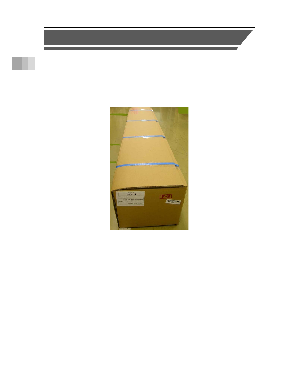
2.1 Precautions for transportation
2-1
2. Installation
2.1 Precautions for transportation
[Handling the package]
● Do not damage or drop the package.
The package is not specially designed to withstand dropping or shock due to collision.
● Keep the unit in horizontal orientation for stationary positioning or transportation.
● Do not climb onto the package.
● Do not put anything that could deform the package on it.
Page 59

2.1 Precautions for transportation
2-2
2. Installation
[Handling after unpacking]
● Hold the base part when you carry the unit.
● Do not carry the unit by its motor cover or stainless steel sheet.
● Do not damage or drop the package during transportation.
● Do not apply excessive force to any part of the actuator.
→For the names of each part, refer to "Names of the Parts" on page Intro-11, 12.
[Handling when assembled into machinery (system)]
● Fix the slider so they would not accidently move during transportation.
● If the actuator or any moving part is overhanging, fix it appropriately to avoid large wobbles due to
external vibration.
When transporting without fixing the tip, do not apply impact of 0.3G or more.
● When suspending machinery (system) with ropes, be careful not to catch the rope on the actuator
or cable.
Page 60

2.2 Installation and storage/preservation environment
2-3
2. Installation
2.2 Installation and storage/preservation environment
Usage is possible in environments of pollution degree 2 or equivalent.
Pollution degree 2: Environment in which generally only nonconductive pollution occurs,
but temporary conductive pollution may occur due to condensation
(IEC 60664-1)
Installation Environment
The actuator should be installed in a location other than those specified below.
In general, the installation environment should be one in which an operator can work without
protective gear.
● Where the actuator receives radiant heat from strong heat sources such as heat treatment
furnaces
● Where the ambient temperature exceeds the range of 0 to 40°C
● Where the temperature changes rapidly and condensation occurs
● Where the relative humidity exceeds 85% RH
● Where the actuator receives direct sunlight
● Where the actuator is exposed to corrosive or combustible gases
● Where the ambient air contains a large amount of powder dust, salt or iron (at level exceeding
what is normally expected in an assembly plant)
● Where the actuator is subject to splashed water, oil (including oil mist or cutting fluid) or
chemical solutions
● Where the actuator receives impact or vibration
● Where the altitude is more than 2,000m
Also, provide sufficient work space for the following maintenance and inspection:
● Space to replenish grease
● Space to replace the motor
If the actuator is used in any of the following locations, provide sufficient shielding measures:
● Where noise generates due to static electricity, etc.
● Where the actuator is subject to a strong electric or magnetic field
● Where the actuator is subject to ultraviolet ray or radiation
Page 61

2.2 Installation and storage/preservation environment
2-4
2. Installation
Storage/preservation environment
● For the storage and preservation environment, see the installation environment.
However, give especial consideration to the prevention of condensation during long-term
storage/preservation.
● Unless especially specified, desiccant is not included in the package at shipping.
If the product is to be stored/preserved in an environment where condensation is anticipated,
take condensation preventive measures.
● For short-term storage, it can be stored at 60°C or below.
For storage of one month or more, make sure that the temperature does not exceed 50°C.
● The product should be placed horizontally for storage and preservation.
If storing in the packaged condition, observe the conditions, if any, regarding storage
orientation.
Page 62

2.3 How to Install
2-5
2. Installation
2.3 How to Install
Installation Orientation
Type: RCS4 –SA4/SA6/SA7/SA8
Horizontal installation Vertical installation
Sideway installation Ceiling mount installation
Caution
When installing the unit vertically, keep the motor on top to the greatest extent
possible.
If the motor is installed on the bottom, the grease may separate due to long-term disuse,
causing the base oil to flow into the motor part. The controller and motor/encoder may
break down due to the entry of the base oil.
Page 63

2.3 How to Install
2-6
2. Installation
Precautions regarding stainless steel sheet
● During installation and transport, do not grasp or press on the stainless steel sheet.
Otherwise, this may lead to stainless steel sheet damage.
● Although lateral or ceiling installation is possible, it may cause slackness or
misalignment of the stainless steel sheet.
Continued usage in this orientation may lead to damage to the stainless steel sheet.
● Adjust the stainless steel sheet if slackness or misalignment occurs.
● Keep adhesive, paint, and other viscous material off the stainless steel sheet.
Such material adhering to the stainless steel sheet can lead to defective slider
operation or sheet damage.
Avoid installation in environments of this kind, or take safety measures to prevent
adhesion.
Page 64

2.3 How to Install
2-7
2. Installation
Installation surface
● The body mounting surface should be a machined surface or a plane with similar accuracy,
with flatness within 0.05mm/m.
● The mounting frame should have a structure rigid enough to prevent the generation
of vibration, etc.
● Also consider enough space necessary for maintenance work such as actuator replacement
and inspection.
● The bottom surface and both side surfaces of the body base serve as the reference surfaces
for slider running accuracy.
Use these surfaces as the reference surfaces for mounting when running accuracy is required.
When mounting using the side reference surface, machine the installation surface according to
the figure below.
A dimension
SA4
SA6
SA7
2 to 4mm
SA8 3 to 5mm
R0.3 or less
基準⾯
基準⾯
基準⾯有効範囲
Reference
surfaces
Reference
surfaces
Reference surfaces effective range
Page 65

2.3 How to Install
2-8
2. Installation
Installation of the Main Unit
[When using the tapped holes on the bottom of the base]
The unit has a tapped holes at the bottom of the base for mounting.
It can be affixed at the back using the tapped holes.
→For details regarding the position and dimensions,
Refer to "Chapter 5 External Dimensions".
Dimensions for Tapped Hole Positions
Model
Name
Tap ped
Hole
Size
Tapped Holes Depth Reamed Hole (mm) Oblong Hole
SA4C
SA4R
M4
Through
(screwing depth should be
6mm or less)
φ
3H7 Depth 4
A:3 B:4 Depth 4mm or less
SA6C
SA6R
M5
Through
(screwing depth should be
10mm or less)
φ
4H7 Depth 5.5
A:4 B:5 Depth 5.5mm or less
SA7C
SA7R
M5
Through
(screwing depth should be
10mm or less)
φ
4H7 Depth 6
A:4 B:5 Depth 6mm or less
SA8C
SA8R
M6
Through
(screwing depth should be
12mm or less)
φ
6H7 Depth 6.5
A:6 B:7 Depth 6.5mm or less
+0.010
0
Oblong
Hole
Through
Hole
Reference
surface
Tapped
Hole
Oblong
Hole
Reamed
Hole
B
A
+0.012
0
+0.012
0
+0.012
0
Page 66

2.3 How to Install
2-9
2. Installation
[Tightening Torque]
Model Name Tapped Hole
Tightening Torque Reamed Hole (mm)
In the case that steel is used for
the bolt seating surface:
In the case that aluminum is used
for the bolt seating surface:
SA4C
SA4R
M4
3.59N•m
(0.37kgf•m)
1.76N•m
(0.18kgf•m)
SA6C
SA6R
M5
7.27N•m
(0.74kgf•m)
3.42N•m
(0.35kgf•m)
SA7C
SA7R
M5
7.27N•m
(0.74kgf•m)
3.42N•m
(0.35kgf•m)
SA8C
SA8R
M6
12.3N•m
(1.25kgf•m)
5.4N•m
(0.55kgf•m)
Notice
● The use of high-strength bolts of ISO-10.9 or higher is recommended.
● Make sure the internal thread and bolt effective engagement length is
approximately 1.8 times the nominal diameter or more.
Page 67

2.3 How to Install
2-10
2. Installation
[Using the Through Holes on the Top of the Base]
As SA4, SA6 and SA7 are equipped with through holes on the base for purpose of
installation from the top, it is available to screw in from the top side.
Detach the side covers on the sides when installing.
For mounting bolts, use hexagonal socket head bolts indicated in the following
table depending on the platform material.
Model
Name
Through Hole Mounting Bolt
Tightening
Tor que
SA4C
SA4R
φ3.4 drilled hole, 6.5 counter
boring depth 3.5
M3
0.83N•m
(0.085kgf•m)
SA6C
SA6R
φ4.5 drilled hole ,8 counter
boring depth 4.5
M4
1.76N•m
(0.18kgf•m)
SA7C
SA7R
φ6 drilled hole, 9.5 counter
boring depth 5.5
M5
3.42N•m
(0.35kgf•m)
Page 68

2.3 How to Install
2-11
2. Installation
Detaching Side Cover
● Remove 4 attachment screws (+) with a Philips screwdriver.
● The slider cannot be driven only with ROBO Cylinder itself if it is equipped with a brake.
Connect a controller and have JOG operation to move the slider to perform installation.
Caution
Attempt not to drop the bolts, tools, etc. on the stainless steel sheet when tightening the
bolts. Please avoid making a dent mark or scratches.
For the side-mounted specification models of SA4R, SA6R, and SA7R, the side cover
and motor cover interfere each other so that they cannot be removed as they are.
Remove the motor cover and detach the side cover.
[For removing direction of the motor cover, refer to Motor Replacement in “4.6 How to
replace components”]
Notice
● The use of high-strength bolts of ISO-10.9 or higher is recommended.
● Make sure the internal thread and bolt effective engagement length is
approximately 1.8 times the nominal diameter or more.
Page 69

2.3 How to Install
2-12
2. Installation
[When Using Attachment Holes on Bracket in Motor Reversing Type]
As there are tapped holes on the reversing bracket, it is available to screw in from the back.
It should be an option (Model: RP) for SA4R.
● For SA4R (Option)
● For SA6R
Model Name A B
Attachment
Hole
Diameter
Attachment Hole
Depth
Tightening Torque
SA4R 32 10 M4 8mm
1.76N•m
(0.18kgf•m)
SA6R 47 9.5 M5 10mm
3.42N•m
(0.35kgf•m)
4M A
A
B
4M
A
A B
Page 70

2.3 How to Install
2-13
2. Installation
● For SA7R and SA8R
Notice
● The use of high-strength bolts of ISO-10.9 or higher is recommended.
● Make sure the internal thread and bolt effective engagement length is
approximately 1.8 times the nominal diameter or more.
Model Name A B
Attachment
Hole
Diameter
Attachment Hole
Depth
Tightening Torque
SA7R 58 6.5 M6 12mm
5.4N•m
(0.55kgf•m)
SA8R 58 8 M6 12mm
5.4N•m
(0.55kgf•m)
4M
A
A
B
Page 71

2.3 How to Install
2-14
2. Installation
[Precautions when using reversing brackets]
● Availability of installation for each installation posture is as shown below:
Caution
Do not attempt to affix the unit only with the tapped holes on the side-mounted bracket.
Do not apply external force to the actuator body after installation.
External force may cause malfunctions or damage to parts.
Installation Posture
Support
Horizontal Vertical
Ceiling
Mount
× × × No
○ ○ × Yes
天吊り
外力
外力
垂直
水平
取付不可
External Force
External Force
Horizontal
Vertical Ceiling Mount
Unmountable
Page 72

2.3 How to Install
2-15
2. Installation
[Precautions for horizontal mounting using reversing brackets]
● Prepare a support block for the body, as shown in the figure below.
支持台
Support block
Page 73

2.3 How to Install
2-16
2. Installation
Mounting transported objects
[For SA4C/R, SA6C/R, SA7C/R]
● Use the tapped mounting holes on the top surface of the slider to fix transported objects.
● There are 4 reamed holes on the top surface of the slider.
Use these reamed holes if repeated attaching and detaching is required.
● If fine-tuning of perpendicularity, etc. is required, use one of the reamed holes
for this adjustment.
● Refer to the figure below for the screw-in depth and reamed hole depth.
Model
Name
A B C Reamed Hole
Tapped Hole
M
Mounting Bolt
Bolt Nominal
Diameter
Tightening Torque
SA4C,
SA4R
20 24 32 φ3H7Depth6 M3Depth7 M3 0.83N•m(0.085Kgf•m)
SA6C,
SA6R
31 32 50 φ5H7Depth6 M5Depth10 M5 3.42N
•
m(0.35Kgf•m)
SA7C,
SA7R
39 42 65 φ5H7Depth10 M5Depth10 M5 3.42N•m(0.35Kgf•m)
Pitch tolerance from reamer ± 0.02
Page 74
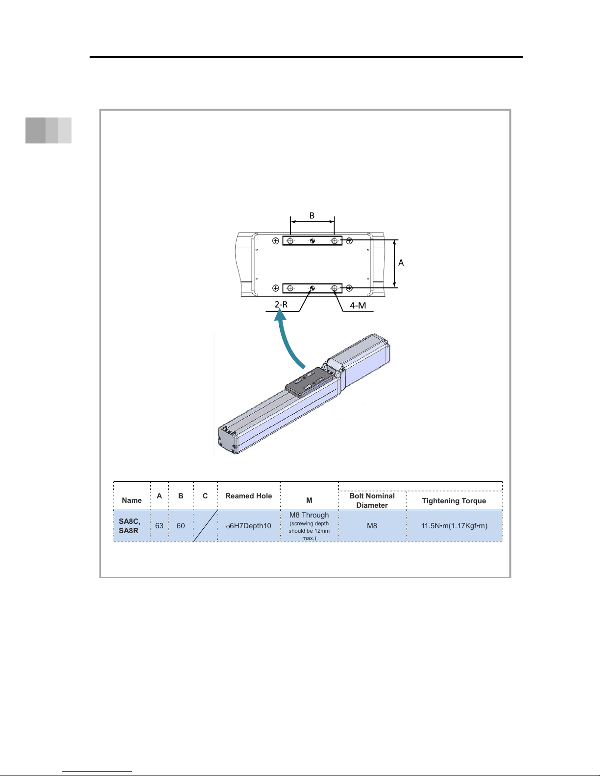
2.3 How to Install
2-17
2. Installation
[For SA8C/R]
● Use the tapped mounting holes on the top surface of the slider to fix transported objects.
● There are 2 reamed holes on the top surface of the slider.
Use these reamed holes if repeated attaching and detaching is required.
● If fine-tuning of perpendicularity, etc. is required, use one of the reamed holes
for this adjustment.
● Refer to the figure below for the screw-in depth and reamed hole depth.
Model
Name
A B C Reamed Hole
Tapped Hole
M
Mounting Bolt
Bolt Nominal
Diameter
Tightening Torque
SA8C,
SA8R
63 60 φ6H7Depth10
M8 Through
(screwing depth
should be 12mm
max.)
M8 11.5N•m(1.17Kgf•m)
Pitch tolerance from reamer ± 0.02
Page 75

2.3 How to Install
2-18
2. Installation
Caution
Be careful with regard to the length of the mounting bolt and positioning pin.
The use of screw-in depth greater than that of the tapped or reamed mounting
holes may damage the tapped hole or reduce the mounting strength of the
transported object, leading to decreased accuracy or unexpected accidents.
Notice
● The mounting bolts are to be prepared by the customer.
● The use of high-strength bolts of ISO-10.9 or higher is recommended.
Page 76

2.3 How to Install
2-19
2. Installation
About Suction of the Cleanroom Type
● Cleanroom type actuators are able to exert performance corresponding to cleanroom class
10 (0.1μm, Fed.Std.209D) and class 2.5 equivalent (ISO 14644-1) by aspirating air from
the vacuum joint.
The guidelines of the suction amounts for the rated speeds of each model are shown in the
following table.
[Suction amount guideline]
Single slider specification
Model Number Lead [mm]
Suction Amount
Nl/min (L/min)
SA4C
16 60(65)
10 40(43)
5 20(22)
2.5 10(11)
SA6C
20 100(108)
12 70(76)
6 30(32)
3 15(16)
SA7C
24 90(97)
16 70(76)
8 40(43)
4 30(32)
SA8C
20 160(173)
10 80(86)
5 40(43)
Page 77
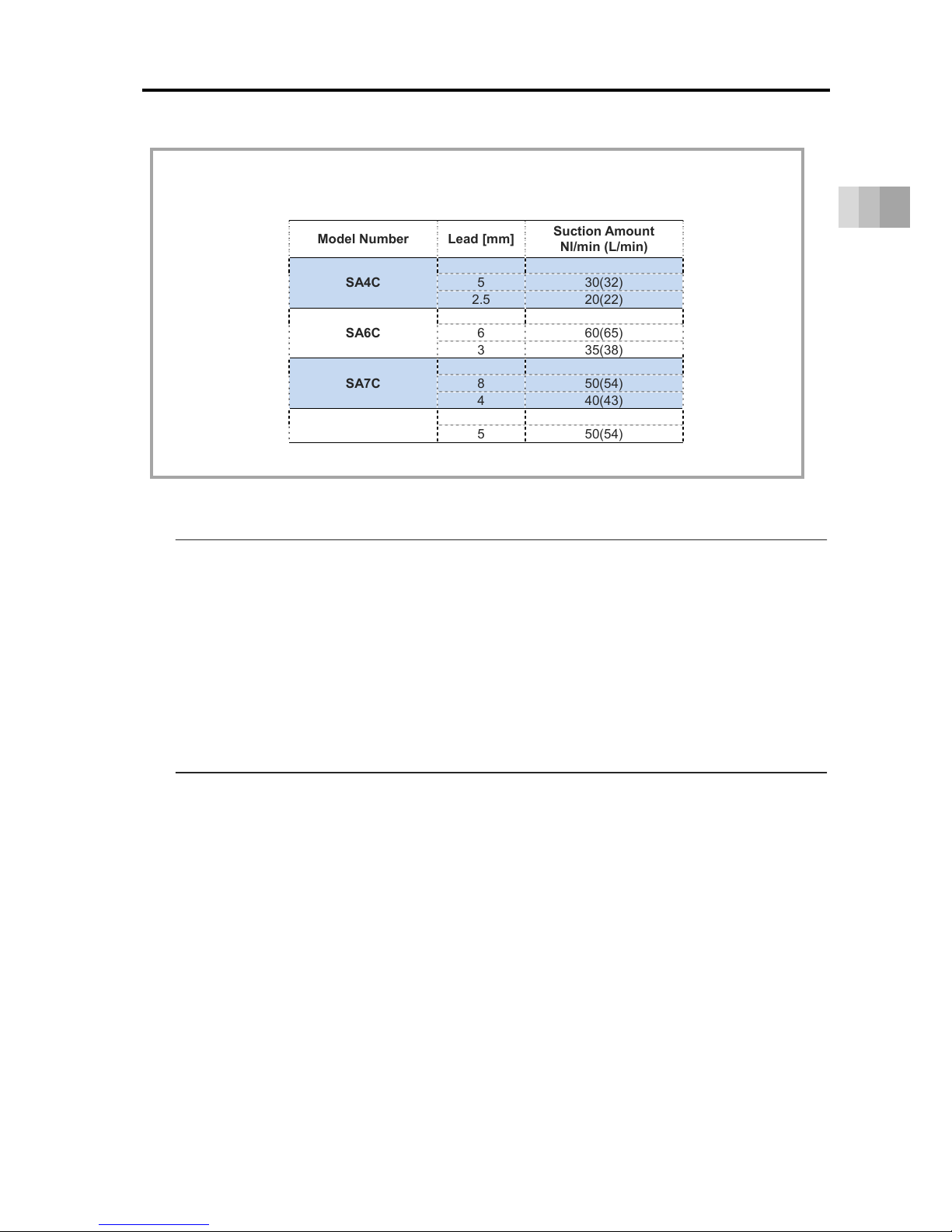
2.3 How to Install
2-20
2. Installation
[Suction amount guideline]
Double slider specification (option model W)
Model Number Lead [mm]
Suction Amount
Nl/min (L/min)
SA4C
10 60(65)
5 30(32)
2.5 20(22)
SA6C
12 110(119)
6 60(65)
3 35(38)
SA7C
16 100(108)
8 50(54)
4 40(43)
SA8C
10 120(130)
5 50(54)
Notice
● Please perform suction of air from the two vacuum joints located on the sides of the
actuator according to the suction amounts (total amount of the two locations) shown in
the table below.
Also, please manage the joints so that the suction amounts of the two locations are
equivalent.
● Please use the actuator in a state in which all of the base attachment holes on the
bottom of the actuator are covered. When there is a hole that passes through the
actuator, the level of cleanliness decreases.
Page 78

2-21
2. Installation
Page 79

Connecting with
the Controller
3.1 Connecting with the Controller ··································· 3-1
ROBO Cylinder
Chapter
Page 80
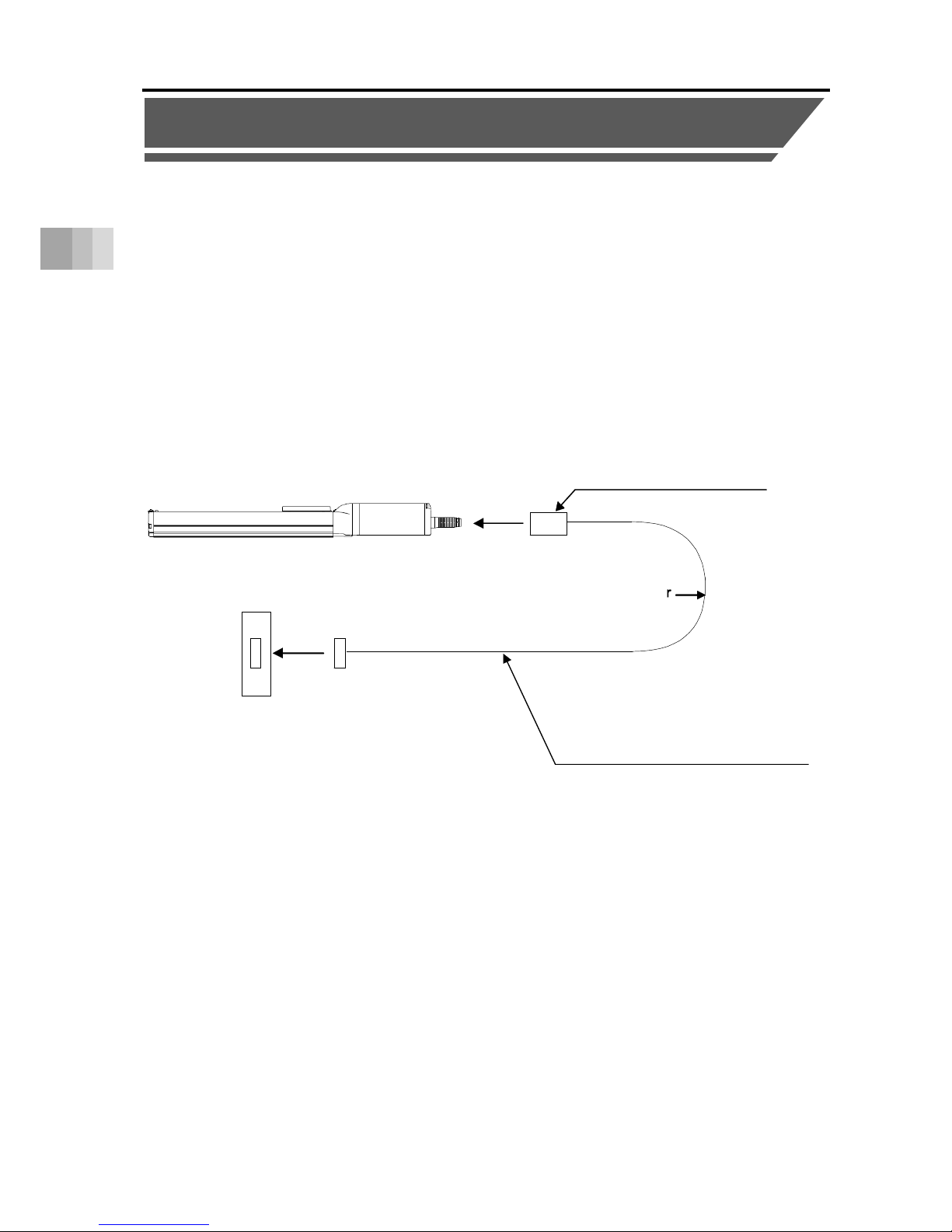
3.1 Connecting with the Controller
3-1
3. Connecting with the Controlle
r
3.1 Connecting with the Controller
As the connection cable for the controller and the actuator, use the IAI-dedicated connection
cable.
Please consult with IAI if you require a different kind of cable than the one supplied.
● If the dedicated connection cable cannot be secured, reduce the load on the cable by allowing
it to deflect only by the weight of the cable or wire it in a self-standing cable hose, etc., having a
large radius.
● Do not cut and reconnect the dedicated connection cable for extension or shorten the cable.
● Do not pull on the dedicated connection cable or bend it forcibly.
● The actuator cable coming out of the motor unit is not meant to be bent. Fix the cable so it
would not be bent repeatedly
Dedicated Connection Cable
Robot Cable
: r=51mm or more (movable use)
: r=46mm or more (fixed use)
Dedicated Controller
Dedicated Cable
● Motor Cables: CB-RCC-MA□□□
● Motor Robot Cables: CB-RCC-MA□□□-RB
● Encoder Robot Cables: CB-X1 -PA□□□
* □□□ represents the cable length. The longest corresponds to 20m.
e.g.) 080 = 8m
● SCON-CB
/
CGB
● SCON-CAL/CGAL
● SCON-LC/LCG
● MSCON-C
● SSEL-CS
● XSL-P/Q/R/S/RA/SA
RCS4 (CR)-××
Page 81

3.1 Connecting with the Controller
3-2
3. Connecting with the Controller
Caution
For wiring, please follow the warnings stated below. When constructing a system as the machinery
equipment, pay attention to the wiring and connection of each cable so they are conducted properly.
Not following them may cause not only a malfunction such as cable breakage or connection failure,
or an operation error, but also electric shock or electric leakage, or may even cause a fire.
Use dedicated cables of IAI indicated in this instruction manual. Contact us if you wish to have a
change to the specifications of the dedicated cables.
Make sure to turn the power off in the process of power line or cable connection or disconnection.
Do not attempt to cut a dedicated cable with connectors on both ends to extend, shorten or re-joint it.
Hold the dedicated cable to avoid mechanical force being applied to the terminals and connectors.
Use a cable pipe or duct to have an appropriate protection when there is a possibility of mechanical
damage on a dedicated cable.
In case a dedicated cable is to be used at a moving part, make sure to lay out the cable without
applying any force to pull the connector or extreme bend on the cable. Do not attempt to use the
cable with a bending radius below the allowable value.
Make certain that the connectors are plugged properly. Insufficient connection may cause an
operation error, thus it is extremely risky.
Do not lay out the cables to where the machine runs over them.
Pay attention to the cable layout so it would not hit peripherals during an operation. In case it does,
have an appropriate protection such as a cable track.
When a cable is used hanging on the ceiling, prevent an environment that the cable swings with
acceleration or wind velocity.
Make sure there is not too much friction inside the cable storage equipment.
Do not apply radiated heat to power line or cables.
Page 82
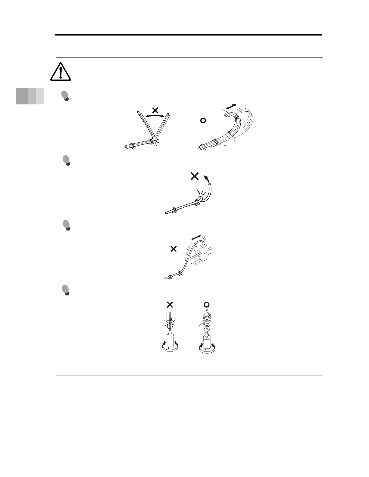
3.1 Connecting with the Controller
3-3
3. Connecting with the Controlle
r
Caution
Have a sufficient radius for bending, and avoid a bend concentrating on one point.
Do not let the cable bend, kink or twist.
Do not pull the cable with a strong force.
Pay attention not to concentrate the twisting force to one point on a cable.
Tie them up softly.
Steel Strap
Page 83

3.1 Connecting with the Controller
3-4
3. Connecting with the Controller
Caution
Do not pinch, drop a heavy object onto or cut the cable.
When a cable is fastened to affix, make sure to have an appropriate force and do not tighten too
much.
PIO line, communication line, power and driving lines are to be put separately from each other and
do not tie them together. Arrange so that such lines are independently routed in the duct.
Do not use spiral tube in any position
where cables are bent frequently.
Duct
I/O Lines
Power Line
Page 84

3.1 Connecting with the Controller
3-5
3. Connecting with the Controlle
r
Caution
Follow the instructions below when using a cable track.
If there is an indication to the cable for the space factor in a cable track, refer to the wiring instruction
given by the supplier when storing the cable in the cable track.
Avoid the cables to get twined or twisted in the cable track, and also to have the cables move freely
and do not tie them up. (Avoid tension being applied when the cables are bent.)
Do not pile up cables. It may cause faster abrasion of the sheaths or cable breakage.
Page 85

Maintenance and Inspection
4.1 Precautions for maintenance and inspection work ·········· 4-1
4.2 Inspection Items and Schedule ·································· 4-3
Slider type ··············································································· 4-3
Grease supply timing (Guideline) ················································· 4-3
4.3 Visual inspection items ············································· 4-4
External visual inspection ··························································· 4-4
Internal visual inspection ···························································· 4-5
4.4 Cleaning ······························································· 4-7
External cleaning ······································································ 4-7
Internal Cleaning ······································································ 4-7
4.5 Greasing method ···················································· 4-8
Grease used ············································································ 4-8
Greasing method ······································································ 4-10
4.6 How to replace components ······································ 4-13
Stainless steel sheet replacement/adjustment ································ 4-13
Belt replacement/adjustment ······················································· 4-19
Motor Replacement ··································································· 4-24
ROBO Cylinder
Chapter
Page 86

4.1 Precautions for maintenance and inspection work
4-1
4. Maintenance and Inspection
4.1 Precautions for maintenance and inspection work
Make sure to read the following precautions before conducting any maintenance or inspection
work.
Caution
Do not climb on or put anything on the actuator.
Otherwise, this may lead to accidental falling, injury or damage to the product due to
falling objects, product loss of function or performance degradation, or shortening of
product life.
Before releasing the brake, make sure to check there is nothing that will interfere with
moving parts within the operation range.
The slider may fall, possibly injuring the operator or people nearby and damaging the
actuator, workpiece or equipment.
Caution
Check that the power to the actuator is OFF before conducting any maintenance or
inspections.
Be careful not to lose the cover or any removed screws.
Be sure to return the product to the original condition after maintenance and inspection
work.
Mounting in an incomplete state may cause injuries or damage to the product.
Do not modify, disassemble/assemble, or use maintenance parts not specified on your
own discretion under any circumstances.
Page 87

4.1 Precautions for maintenance and inspection work
4-2
4. Maintenance and Inspection
Caution
The grease film may run out if the actuator performs return operation continuously over a
distance of 30mm or less. As a guideline, every 5,000 to 10,000 cycles, have
approximately 5 cycles of return operation over a 50mm distance or more to regenerate
the oil film.
The ball screw or guide may be damaged if the oil film runs out.
Notice
● First, be sure to wipe off the old grease, and then supply new grease.
● The degradation speed of grease may differ depending on the operating environment
(temperature, humidity and ambient atmosphere).
It is recommended to shorten the grease supply period if the actuator is used under poor
environmental conditions such as high temperatures, high humidity or dusty
atmospheres.
● Also, it is recommended to improve the environmental conditions in case the grease
changes color notably due to poor operating conditions.
● Base oil may separate from the grease due to the mounting orientation or operating
conditions.
Base oil may also leak from the inside of the actuator to the exterior through gaps.
Check visually for oil drips when supplying grease.
● An actuator stored for 6 months or more may suffer from grease degradation.
Supply grease before the start of use.
→For details, refer to "4.5 Greasing method".
Page 88

4.2 Inspection Items and Schedule
4-3
4. Maintenance and Inspection
4.2 Inspection Items and Schedule
Follow the maintenance inspection schedule below.
It is assumed that the equipment is operating 8 hours per day.
If the equipment is running continuously night and day or otherwise running at a high operating
rate, inspect more often as needed.
Slider type
*Stainless steel sheet life guideline: 5,000km
Inspection period
External
inspection
Internal
inspection
Greasing
Ball screw Guide
Start of work inspection
○ - - -
1-month inspection
○ - - -
3-month inspection
- - ○ ○
3-month inspection on
- -
Grease supply timing
(Guideline) dependent
6-month inspection
○ ○
Every 6 months thereafter
○ ○
Grease supply timing (Guideline)
Maximum operating speed [mm/s]
Grease supply timing (Guideline)
Operation distance Months
0 to 750 or less 1,250km
12 months
750 to 1500 or less 2,500km
1500 to 2200 5,000km
Page 89

4.3 Visual inspection items
4-4
4. Maintenance and Inspection
4.3 Visual inspection items
Refer to "4.6 How to replace components" for detailed information about specific component
replacement and adjustment methods.
External visual inspection
Inspection items Maintenance work
Is abnormal noise or vibration generated?
Take an action by referring to
“Troubleshooting in Controller Instruction
Manual”.
Are actuator mounting bolts loose? Tighten them further.
Is the cable scratched? Replace if the damage is severe.
Is the connector loose? Re-insert correctly.
Is grease dripping out?
(especially if vertically mounted)
Clean up any drips.
Replenish the grease.
Is the stainless steel sheet scratched? Replace the stainless steel sheet.
Is the stainless steel sheet misaligned or
slack?
Adjust the alignment and hang.
Page 90
4.3 Visual inspection items
4-5
4. Maintenance and Inspection
Refer to "4.6 How to replace components" for detailed information about specific component
replacement and adjustment methods.
Internal visual inspection
Inspection items Maintenance work
Backlash/play or wear debris found?
The ball screw guide may be damaged.
Contact IAI.
Has foreign matter penetrated inside?
Remove the foreign matter, clean, and inspect
the interior for any damage.
Is the ball screw or guide grease not
lubricating well?
(Even if the grease is brown, lubrication is
adequate if the running surface is shiny )
Wipe away the old grease, then replenish with
new grease.
Is dust or foreign matter adhered to the
ball screw or guide?
Replenish with new grease after cleaning.
Internal inspection method
1) Loosen the screws on the side cover and detach the side cover.
2) Check inside.
3) After finishing the inspection, assemble back in the reverse order. If you touch the
edge of the stainless steel sheet in the attaching the side cover process, the sheet
may get damaged or wavy which result in shortening life or earlier wear-out.
To avoid touching the edge of the sheet, insert a spacer (approximately 0.1 to 0.2mm)
between the sheet and cover to push up the sheet, and then push in the cover.
When affixing the side cover, tighten the screws with the tightening torque described
below.
Screw Diameter Tightening Torque
M3 41.4N•cm
4) Make sure that the slider and the side cover do not interfere, moving the slider
backwards and forwards between the strokes.
Page 91

4.3 Visual inspection items
4-6
4. Maintenance and Inspection
Caution
Do not damage the stainless steel sheet by bending it forcefully during internal
inspection.
Do not tug on the stainless steel sheet or in any way attempt to reposition it.
Change in the attached condition may cause the sheet to be mounted unevenly or
impact the product life.
Keep in mind that the edges of the stainless steel sheet can cause injuries.
Always wear gloves when working on it.
Page 92

4.4 Cleaning
4-7
4. Maintenance and Inspection
4.4 Cleaning
External cleaning
● Clean exterior surfaces as necessary.
● Use a soft cloth to wipe away dirt and buildup.
● Do not blow too hard with compressed air as it may cause dust to get in through the gaps.
● Do not use oil-based solvents as they can harm lacquered and painted surfaces.
● To remove severe buildup, wipe gently with a soft cloth soaked in a neutral detergent
or alcohol.
Internal Cleaning
● Use a soft cloth to wipe away dirt and buildup.
● Do not blow too hard with compressed air as it may cause dust to get in through the gaps.
● Do not use oil-based solvents, neutral detergent or alcohol.
Page 93
4.5 Greasing method
4-8
4. Maintenance and Inspection
4.5 Greasing method
[1] Grease used: Use an equivalent product
~ Standard Type: Except for Lead 30 in SA6, Lead 36 in SA7 or Lead 48 in SA8
Application
location
During maintenance
(recommended product)
Default (reference)
Ball screw
Kyodo Yushi/Multemp LRL No.3 Kyodo Yushi/Multemp LRL No.3
Guide
Caution
Never use fluorine-based grease and urea-based grease.
Mixing with lithium-based grease not only reduces the performance of the grease, it
may even cause damage to the actuator.
~ Standard Type: Lead 30 in SA6, Lead 36 in SA7 and Lead 48 in SA8
Application
location
During maintenance
(recommended product)
Default (reference)
Ball screw
Kyodo Yushi/Multemp ET-R No.2 Kyodo Yushi/Multemp ET-R No.2
Guide
Caution
Never use lithium-based grease and fluorine-based grease.
Mixing with urea-based grease not only reduces the performance of the grease, it
may even cause damage to the actuator.
Page 94
4.5 Greasing method
4-9
4. Maintenance and Inspection
~ Cleanroom Type
Application
location
During maintenance
(recommended product)
Default (reference)
Ball screw
Kuroda Precision Industries/C grease Kuroda Precision Industries/C grease
Guide
Caution
For grease to be used with an actuator that has a cleanroom setting, please use a type of
grease that emits a low amount of dust and is described for cleanroom use.
When standard grease is used, dust may be emitted.
Never use lithium-based grease and fluorine-based grease.
Mixing with urea-based grease not only reduces the performance of the grease, it
may even cause damage to the actuator.
Page 95
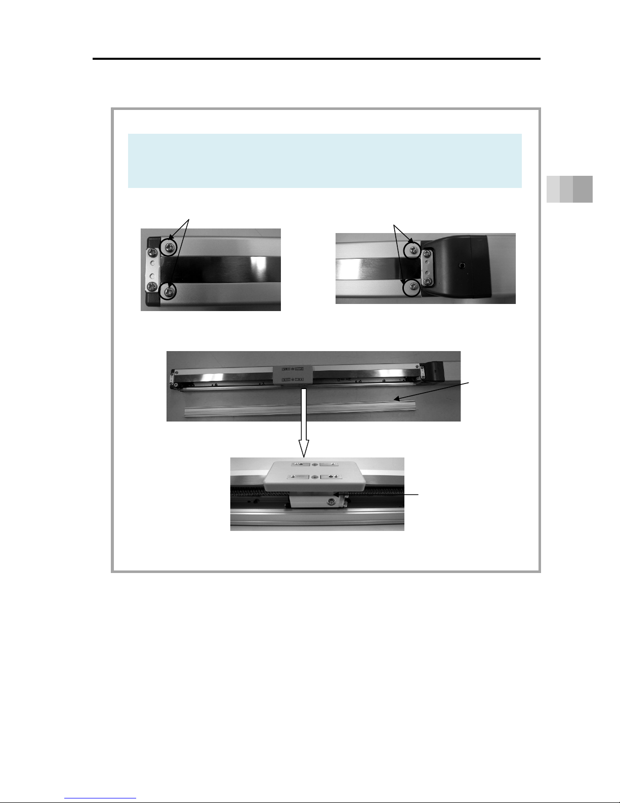
4.5 Greasing method
4-10
4. Maintenance and Inspection
[2] Greasing method: Ball screw/guide (supply to both through grease fitting)
Greasing method
1) Remove the screw and detach the side cover on either side, right or left.
The grease nipple will appear.
(Note) When the side cover on the other side has been detached, the other grease
nipple also appears.
Motor Side
Opposite Side
Side Cover
Attachment Screws
Grease Nipple
There is one
on the other side.
After removal of the side cover on either side
Side Cover
Side Cover
Attachment Screws
Page 96

4.5 Greasing method
4-11
4. Maintenance and Inspection
2) Supply grease from the grease nipple on either side, using the grease gun.
Wipe off the grease before supplying new in case it is extremely dirty.
(Note) Grease can also be applied from the grease nipple on the other side.
When grease is applied from the grease nipple on either side, grease is supplied
to the ball screw and the guides on both sides.
(Note) Make sure to use a grease gun that is applicable for the grease nipple inlet diameter
shown below.
Grease Nipple Diameter
φ
3.5
Grease Gun Nozzle Supplier of nozzle
Grease gun of mounting screw R1/8
(Example) GC-57K (Yamada Corporation)
NZ3 NSK
Model Name
Amount of Grease Supply
(Reference)
SA4 0.5cc to 1.0cc
SA6 1.5cc to 2.0cc
SA7 2.0cc to 2.5cc
SA8 3.5cc to 4.0cc
Move the slider back and forth in the stroke range after supplying grease so it spreads out
evenly in the area.
• Confirm that the ball tracks on the ball screw and guide look glossy with oil of grease.
Supply grease again if it is not spread enough.
• Wipe off excess grease.
Caution
Supplying too much grease may increase sliding resistance and load to the motor, resulting
in a drop of performance.
Also, excess grease on the ball screw may be splashed around in the ambience.
Grease Gun
Page 97

4.5 Greasing method
4-12
4. Maintenance and Inspection
3)
Attach the side covers after grease supply is finished.
If you touch the edge of the stainless steel sheet in the attaching process, the sheet
may get damaged or wavy which result in shortening life or earlier wear-out.
To avoid touching the edge of the sheet, insert a spacer (approximately 0.1 to 0.2mm)
between the sheet and cover to push up the sheet, and then push in the cover.
When affixing the side cover, tighten the screws with the tightening torque described
below.
Screw
Diameter
Tightening Torque
M3 41.4N•cm
4) Make sure that the slider and the side cover do not interfere, moving the slider
backwards and forwards between the strokes.
Caution
Do not damage the stainless steel sheet by bending it forcefully during work.
Keep in mind that the edges of the stainless steel sheet can cause injuries. Always wear
gloves when working on it.
The front bracket is supporting the ball screw. Do not detach it.
If the front bracket loses its tuned condition, it may cause an increase of driving
resistance, shortened life of each component or abnormal noise due to the center of the
axis being off the right position.
In case the grease got into your eye, wash it with clean water for 15 minutes and
immediately go see the doctor to get appropriate care.
After finishing the grease supply work, wash your hands carefully with water and soap to
rinse the grease OFF.
Page 98

4.6 How to replace components
4-13
4. Maintenance and Inspection
4.6 How to replace components
Stainless steel sheet replacement/adjustment
Preparation
1) Items required for replacing the stainless steel sheet
• Replacement stainless steel sheet
• Phillips screwdriver
• Scale
Names of the Parts
Caution
Degradation and wear-out of the stainless steel sheet relies on its tension of attachment.
If the stainless steel sheet is pulled with a huge force and the gap between the sheet and
the slider cover is large, there is a risk of metal fatigue.
On the other hand, if the tensile strength is too low, the stainless steel sheet would
interfere with the back side of the slider cover and make dust to be generated.
Stainless Sheet Retainer Plate
Stainless Sheet Retainer Plate
Stainless Steel Sheet
Slider Cove
r
Page 99

4.6 How to replace components
4-14
4. Maintenance and Inspection
Have a replacement and tuning in (1) Procedure 1 for SA7, SA8.
For SA4, SA6 have a replacement and tuning in either (1) Procedure 1 or (2) Procedure 2.
Stainless steel sheet replacement method Procedure 1
1) Remove the screws (4 places) holding the stainless steel sheet and stainless steel
sheet retainer plates (2 pieces) with using a Phillips screwdriver.
2) Pull the old stainless steel sheet till in front of the slider.
Make sure not to pull it out completely off the slider.
3) Join a new stainless steel sheet to the old one with using cellophane tape.
Pull it till in front
of the slider.
In front of Slider
Join with
cellophane tape
Old stainless
steel sheet
New stainless
steel sheet
Page 100

4.6 How to replace components
4-15
4. Maintenance and Inspection
4) Pull the old stainless steel sheet so the new one goes through below the slider.
Pull it till the new stainless steel sheet comes to the edge of the actuator.
5) Remove the old stainless steel sheet.
6) Fix the two stainless steel sheet retainer plates using the screws (four locations).
Use a Phillips screwdriver to attach it.
Tightening Torque
41.4N•cm
7) After the stainless steel sheet retainer plates have been fixed, move the slider from
one side to the other side (full stroke) with your hand to check that there is no rise or
slackness in the stainless steel sheet. If there is any problem, repeat from step 6).
Pull till
the edge
Edge
Pull
Old stainless
steel sheet
New stainless
steel sheet
There are two grooves for stainless steel
sheet attachment guides. Align so that
the stainless steel sheet is positioned at
the center between the two grooves.
Attach the stainless steel sheet so that it
is not bent.
 Loading...