

Page 1
RCS3 Actuator
Loadcell-equipped Rod Type
First Step Guide Third Edition
Thank you for purchasing our product.
Make sure to read the Safety Guide and detailed Instruction Manual (DVD) included with the product in addition to
this First Step Guide to ensure correct use.
This Instruction Manual is original.
• Using or copying all or part of this Instructio n Manual without permission is prohibited.
• The company names, names of products and trademarks of each company shown in the sentences are
registered trademarks.
Product Check
The standard configuration of this product is comprised of the following parts.
If you find any fault or missing parts, contact your local IAI distributor.
1. Parts (Except with Option)
No. Part Name Model Quantity Remarks
1 Actuator Main Body Refer to “How to read the model No.” 1
Accessories
2
Motor • Encoder Cable
(Note 1)
1
3 First Step Guide 1
4 Instruction Manual (DVD) 1
5 Safety Guide 1
Note 1 The motor/encoder cables refer to wiring for the applicable cables.
2. How to read the model plate
3. How to read the model No.
Note 1 Identification for IAI use only : It may be displayed for IAI use. It is not a code to show the model type.
Caution in Handling
1. Handling of the Packed Product
Especially in the transportation and handling do not damage or drop as much as possible.
• An operator should never attempt to carry a heavy package on their own.
• If the shipping box is to be left standing, it should be in a horizontal position.
• Do not step or sit on the package.
• Do not put any load that may cause a deformation or breakage of the package.
2. Handling in Unpacked Condition
[RA4R, RA6R, RA7R, RA8R, RA10R]
Do not carry an actuator by motor unit and a track cover area and the cable or attempt to move it by
pulling the cable.
• Hold the body base when transporting the actuator out the package.
• Do not hit or drop the product while carrying. Especially, pay attention to the side cover.
• Do not give any excessive force to any of the sections in the actuator.
• When transporting an actuator, check the weight and the center of gravity of the actuator in
instruction manual before lifting up on a crane. Pay attention to the center point of gravity as it
differs for each model.
Installation and Storage • Preservation Environment
1. Installation Environment
Do not use this product in the following environment.
In general, the installation environment should be one in which an operator can work without protective
gear.
Also make sure to keep enough work space necessary for maintenance.
• Location exposed to radiant heat from a huge heat source such as the heat treatment
• Location where the surrounding air temperature exceeds the range of 0 to 40°C
• Location where condensation occurs due to abrupt temperature changes
• Location where relative humidity exceeds 85%RH
• Location exposed to direct sunlight
• Location exposed to corrosive gases or combustible gases
• Location exposed to significant amount of dust, salt or iron powder (outside of ordinary assembly
plant)
• Location where water, and oil (includes oil mist and cutting fluid) or chemical is splashed
• Location where the product main body receives vibration or hit impact
• Location where the altitude of 2,000m or more
When using the product in any of the locations specified below, provide a sufficient shield.
• Place subject to electrostatic noise
• Location where exposed to the influence of strong electric or magnetic field
• Location where exposed to the influence of ultraviolet or radiant rays
2. Storage • Preservation Environment
• The storage and preservation environment should comply with the same standards as those for
the installation environment.
• In particular, when the machine is to be stored for a long time, pay close attention to
environmental conditions so that no dew condensation forms. Unless specially specified,
moisture absorbency protection is not included in the package when the machine is delivered.
• In the case that the machine is to be stored and preserved in an environment where dew
condensation is anticipated, take the condensation preventive measures from outside of the
entire package, or directly after opening the package.
• For storage and preservation temperature, the machine withstands temperatures up to 60°C for
a short time, but in the case of the storage and preservation period of 1 month or more, control
the temperature to 50°C or less. Storage and preservation should be performed in the horizontal
condition. In the case it is stored in the packaged condition, follow the posture instruction if any
displayed on the package.
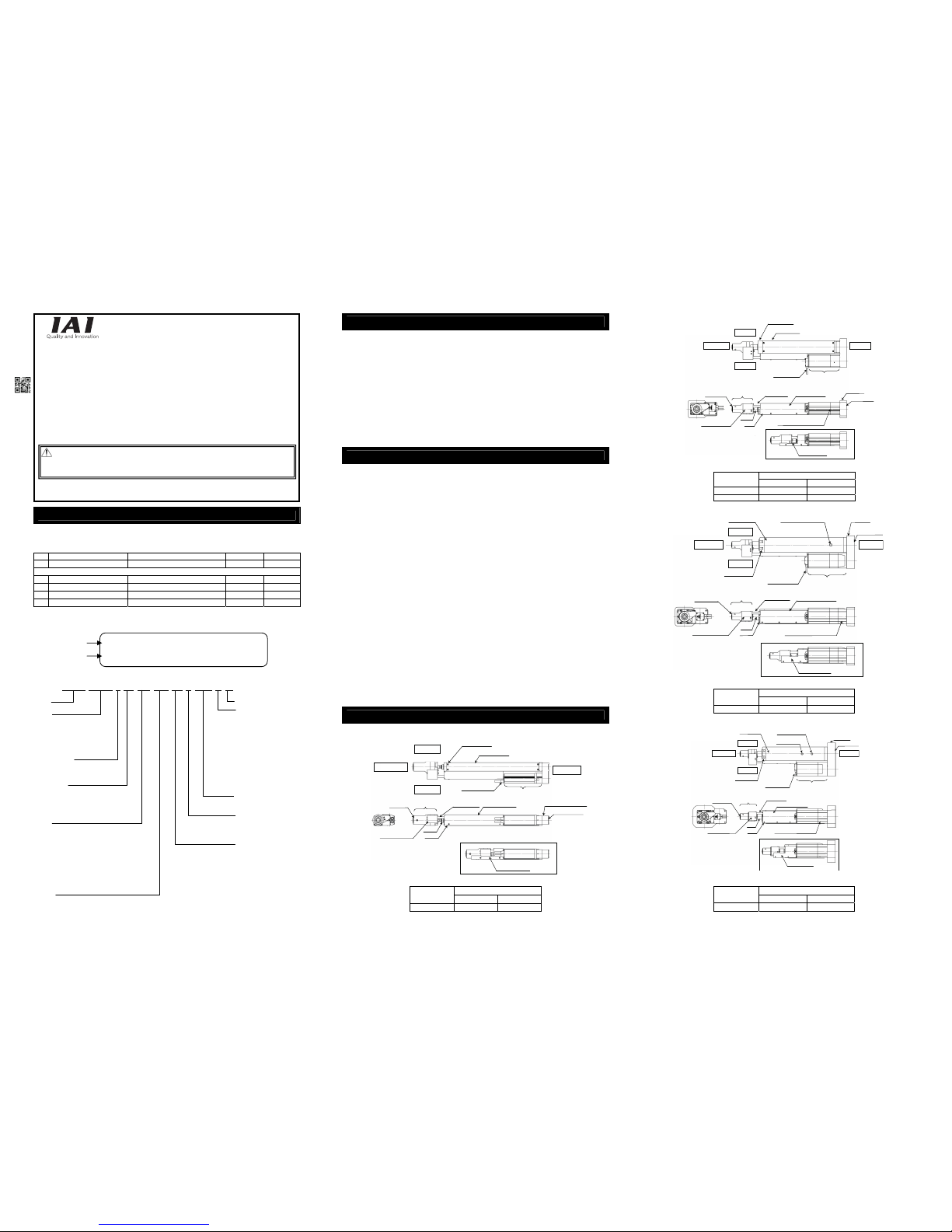
Names of the Parts
1. RA4R
Stroke [mm]
Model
Track Cover 1) Track Cover 2)
RA4R 115 to 265 315 to 415
2. RA6R, RA7R
(Note) The profile of the track cover differs depending on the stroke.
Stroke [mm]
Type
Track Cover 1) Track Cover 2)
RA6R 115 to 265 315 to 415
RA7R 120 to 270 320 to 520
3. RA8R
(Note) The profile of the track cover differs depending on the stroke.
Stroke [mm]
Type
Track Cover 1) Track Cover 2)
RA8R 100 to 250 300 to 500
4. RA10R
(Note) The profile of the track cover differs depending on the stroke.
Stroke [mm]
Type
Track Cover 1) Track Cover 2)
RA10R 100 to 200 250 to 500
Warning : Operation of this equipment requires detailed installation and operation instructions which are
provided on the DVD Manual included in the box this device was packaged in. It should be
retained with this device at all times.
A hardcopy of the Manual can be requested by contacting your nearest IAI Sales Office listed
at the back cover of the Instruction Manual or on the First Step Guide.
Model
Serial number
MODEL RCS3-RA6R-I-50-1.5-115-T2-P-LCT
SERIAL No. A00090266 MADE IN JAPAN
RCS3-RA6R- I-50-1.5-115-T2-P-LCT-B-**
Series
<Type>
Motor Reversing Type
RA4R, RA6R
RA7R, RA8R
RA10R, RA15R
RA20R
<Encoder Type>
I
: Incremental
A : Absolute
<Motor Type>
30 :
30W 50 : 50W
100 :
100W 200 : 200W
300
: 300W 3300 : 3300W
3000
: 3000W
<Lead>
RA4R : 2.5 RA6R :
1.5
RA7R
: 2 RA8R : 2.5
RA10R
: 2.5
RA15R (equipped with loadcell): 3.6
RA20R (equipped with loadcell): 4.0
RA15R
(conveyor type (with no loadcell equipped)): 7.2
RA20R
(conveyor type (with no loadcell equipped)): 10
<Stroke>
[Refer to 1.2 Specifications in
Instruction Manual]
Identification for IAI use only
(Note 1)
<Option>
B : Brake FL:Flange Bracket
FT : Foot Bracket
ML : Motor Left Reversed (Standard)
MR : Motor Right Reversed
MT : Motor Top Reversed
(RA15R, RA20R)
CJT : Cable Eject Direction Changed (Top)
CJO : Cable Eject Direction Changed
(Outside)
CJB : Cable Eject Direction Changed
(Bottom)
CJR : Cable exit direction changed (Right)
(RA15R, RA20R)
CJL : Cable exit direction changed (Left)
(RA15R, RA20R)
CE : Applicable CE (RA4R)
With Loadcell (with Cable Track for Wiring)
When no indication of LCT in RA15R or RA20R
(conveyor type (with no loadcell equipped))
<Cable Length>
N : No Cable P : 1m
S : 3m M : 5m
X□□ : Specified Length
R□□ : Robot Cable
<Controller>
T2 : SCON-CB/CGB
T3 : With loadcell
RA15R
SCON-CGB-3300□F
RA20R
SCON-CGB-3000□F
Conveyor Type (with no loadcell
equipped)
RA15R
SCON-CGB-3300□
RA20R
SCON-CGB-3000□
Loadcell
Loadcell Unit
Track Cover 2)
Motor Unit
Cable Track
Rod
Front Bracket
Actuator Cable
Motor SideOpposite side
Frame Cover
Reversing
Bracket
Right Side
Left Side
Pulley Cover
Loadcell Cover
Tapped Hole for
Ground Cable Connection
Base
Track Cover 1)
Loadcell Loadcell Unit
Motor Unit
Cable Track
Rod
Front Bracket
Actuator Cable
Motor SideOpposite Side
Frame Cover
Reversing
Bracket
Grease Supply on the
Ball Screw and Guide
Right Side
Left Side
Pulley Cover
Loadcell Cover
Tapped Hole for
Ground Cable Connection
Base
Track Cover 2)
Track Cover 1)
Loadcell
Loadcell Unit
Motor Unit
Cable Track
Rod
Front Bracket
Actuator Cable
Motor Side
Opposite Side
Frame Cover
Reversing
Bracket
Grease Supply
on the Ball Screw
Right Side
Left Side
Pulley Cover
Loadcell Cover
Tapped Hole for
Ground Cable Connection
Base
Grease Supply
on the Guide
Track Cover 2)
Track Cover 1)
Pulley Cover
Reversing Bracket
Right Side
Left Side
Loadcell
Base
Rod
Loadcell Cover
Loadcell Unit
Front Bracket
Frame Cover
Cable Track Track Cover 2)
Track Cover 1)
Motor Unit
Actuator Cable
Opposite Side
Motor Side
Page 2
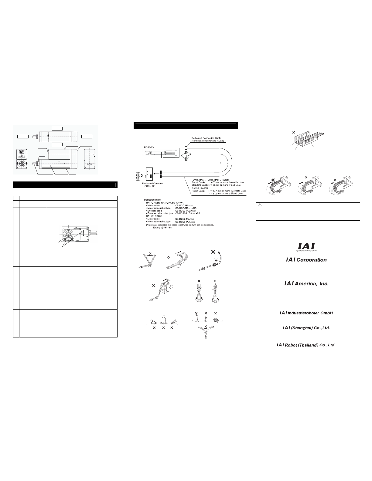
5. RA15R, RA20R
Attachment
Refer to the Instruction Manual (DVD) for the attachments of the actuator and loads.
[Precautions for Attachments]
No. Item Precautions
1 Installation
• Avoid using an actuator equipped with no brake when installing in
vertical orientation
2 Attachment surface
• The base has to have a structure with sufficient rigidity to prevent
oscillation.
• Other than RA15R, RA20R the side and bottom surfaces of the base
on the actuator work as the datum surfaces for the side of the rod.
In
case operation accuracy is required, utilize these surfaces for
installation.
• The actuator mounting surface and other surfaces that are used as a
datum should be flat enough with an accuracy of machining or
equivalent treatment, and the flatness of the mounting surface needs
to be 0.05mm/m or less.
• Secure the space where maintenance work can be performed.
3 Bolts to be used
• For the bolts to be used, a high-tensile bolt complying with ISO-10.9
or more is recommended.
• If using the tapped holes, use screws with the thread length
dimension being less than the effective depth of the holes.
• In case the tapped hole is a through hole, be careful so the screw tip
does not exceed the surface of the tapped hole.
• For the actuator mounting, use a bolt with the dimension of its
effective mating length to the tapped hole size as stated below.
When tapped hole is on female
→ thread length same as nominal diameter.
When tapped hole is on aluminum
→ thread length 1.8 times longer than nominal diameter
However, when installing with using tap holes on actuator, set the
RCS3-RA8R is 12mm or less, and RCS3-RA10R is 15mm or less.
When installing with using front bracket, set the RCS3-RA15R,
RA20R is 18mm or less.
4 Attachment of tool for tip
of the loadcell
(prepared by user)
• Make the weight of the tool lower than the transportable weight of the
actuator.
• When attaching a tool, pay attention not to apply impact load or
unbalanced load to the loadcell or peripheral components. It may
cause malfunction of the loadcell.
• Inside of the loadcell cannot receive force. Make sure not to have a
tool hit on the bottom inside the loadcell. It may cause malfunction of
the loadcell.
• When attaching a tool in horizontal orientation, avoid moment load
from being applied to the loadcell.
Wiring
For the controller, only the dedicated controller manufactured by our company can be used.
Use the dedicated cable enclosed in the package when connecting the actuator and the controller.
[Prohibited Items in the Cable Processing]
• Do not pull or bend forcibly the cable so as not to give any extra load or tension to the cable.
• Do not process the cable to extend or shortening by means of cutting out, combination or connecting
with another cable.
• Do not let the cable bend, kink or twist. • Do not let the the cable flex at a single point.
• Do not pull the cable with a strong force. • Do not let the cable receive a turning force at
a single point.
• Do not pinch, drop a heavy object onto • When fixing the cable, provide a moderate
or cut the cable. slack and do not tension it too tight.
• Separate t he I/O line, communication line and power line from each other.
Do not store in the same duct.
Follow the instructions below when using a cable track.
• If there is an indication to the cable for the space factor in a cab le track, refer to the wiring instruction
given by the supplier when storing the cable in the cable track.
• Avoid the cables to get twined or twisted in the cable track, and also to have the cables move freely
and do not tie them up. (Avoid tension being applied when the cables are bent.)
Do not pile up cables. It may cause faster abrasion of the sheaths or cable breakage.
Head Office: 577-1 Obane Shimizu-KU Shizuoka City Shizuoka 424-0103, Japan
TEL +81-54-364-5105 FAX +81-54-364-2589
website: www.iai-robot.co.jp/
Ober der Röth 4, D-65824 Schwalbach am Taunus, Germany
TEL 06196-88950 FAX 06196-889524
SHANGHAI JIAHUA BUSINESS CENTER A8-303, 808, Hongqiao Rd. Shanghai 200030, China
TEL 021-6448-4753 FAX 021-6448-3992
website: www.iai-robot.com
Technical Support available in USA, Europe and China
Head Office: 2690 W. 237th Street, Torrance, CA 90505
TEL (310) 891-6015 FAX (310) 891-0815
Chicago Office: 110 East State Parkway, Schaumburg, IL 60173
TEL(847) 908-1400 FAX (847) 908-1399
TEL (678) 354-9470 FAX (678) 354-9471
website: www.intelligentactuator.com
Atlanta Office: 1220 Kennestone Circle, Suite 108, Marietta, GA 30066
825 PhairojKijja Tower 12th Floor, Bangna-Trad RD., Bangna, Bangna, Bangkok 10260, Thailand
TEL +66-2-361-4458 FAX +66-2-361-4456
Note:
• When the cable is connected or disconnected, make sure to turn off the power to the controller.
When the cable is connected or disconnected with the controller power turned ON, it might cause a
malfunction of the actuator and result in a serious injury or damage to the machinery.
• When the connector connection is not correct, it would be dangerous because of a malfunction of
the actuator. Make sure to confirm that the connector is connected correctly.
Steel Strap
(Piano Wire)
Tie them up softly.
Do not use spiral tube in any
position where cables are bent
frequently.
Power Line
Duct
I/O Line
(Flat Cable, etc.)
Manual No.: ME3743-3A
Datum Face
Datum Face
Tip Tool
(Loadcell Unit when
model code LCT)
Rod Side Motor Side
Right Side
Connector
Rod
Aluminum Frame
Motor Cover
Base
Left Side
Pulley Cover
*Regenerative resistor units could be
necessary to be connected.
Refer to the Instruction Manual.
/CGB
 Loading...