

Page 1

ROBO Cylinder
RCP5/RCP5CR Actuators
Slider Type
Instruction Manual
Seventh Edition
Standard Type Motor Straight Type: RCP5-SA4C, SA6C, SA7C
Standard Type Motor Reversing Type: RCP5-SA4R, SA6R, SA7R
Cleanroom Type Motor Straight Type: RCP5CR-SA4C, SA6C, SA7C
IAI America, Inc.
Page 2

Page 3

Please Read Before Use
Thank you for purchasing our product.
This instruction manual explains the handling methods, structure and maintenance of this product,
among others, providing the information you need to know to use the product safely.
Before using the product, be sure to read this manual and fully understand the contents explained herein
to ensure safe use of the product.
The DVD that comes with the product contains instruction manuals for IAI products.
When using the product, refer to the necessary portions of the applicable instruction manual by printing
them out or displaying them on a PC.
After reading the instruction manual, keep it in a convenient place so that whoever is handling this
product can reference it quickly when necessary.
[Important]
x This instruction manual is original.
x This product is not to be used for any other purpose from what is noted in this instruction
manual. IAI shall not be liable whatsoever for any loss or damage arising from the result of using
the product for any other purpose from what is noted in the manual.
x The information contained in this instruction manual is subject to change without notice for the
purpose of production improvement.
x If you have any question or finding regarding the information contained in this instruction manual,
contact our customer center or our sales office near you.
x Using or copying all or a part of this instruction manual without permission is prohibited.
x The company names, names of products and trademarks of each company shown in the
sentences are registered trademarks.
Page 4

Page 5

Table of Contents
Safety Guide........................................................................................................... 1
Caution in Handling ................................................................................................ 8
International Standards Compliances ..................................................................... 9
Names of the Parts............................................................................................... 10
1. Specifications Check....................................................................................... 13
1.1 Checking the Product........................................................................................................ 13
1.1.1 Parts..................................................................................................................... 13
1.1.2 Related Instruction Manuals for the Each Controller Supported by
This Product ......................................................................................................... 13
1.1.3 How to Read the Model Nameplate..................................................................... 13
1.1.4 How to Read the Model Number.......................................................................... 14
1.2 Specifications .................................................................................................................... 15
1.2.1 Speed................................................................................................................... 15
1.2.2 Maximum Acceleration and Transportable Mass................................................. 19
1.2.3 Driving System • Position Detector ...................................................................... 36
1.2.4 Positioning Precision............................................................................................ 36
1.2.5 Current Limiting Value and Pressing Force .........................................................37
1.2.6 Allowable Moment of Actuator ............................................................................. 41
1.3 Options .............................................................................................................................. 42
1.3.1 Brake Type (Model : B) ........................................................................................ 42
1.3.2 Reversed-home Specification (Model : NM) ........................................................ 42
1.3.3 Cable Eject Direction Changed (Model No. : CJT, CJR, CJL, CJB, CJO) ........... 42
1.3.4 Motor Left Reversed, Motor Right Reversed (Model No. : ML, MR).................... 42
1.3.5 Slider part roller type (Model No. : SR)................................................................ 43
1.3.6 Slider spacer (Model No. : SS)............................................................................. 43
1.3.7 Air vacuum joint on other side (Model No. : VR).................................................. 43
1.4 Motor • Encoder Cables .................................................................................................... 44
1.4.1 Motor • Encoder Integrated Cables...................................................................... 44
1.4.2 Motor • Encoder Integrated Cables Robot Type .................................................. 45
2. Installation....................................................................................................... 46
2.1 Transportation ................................................................................................................... 46
2.2 Installation and Storage • Preservation Environment........................................................ 48
2.3 How to Install..................................................................................................................... 49
2.3.1 Installation ............................................................................................................ 49
2.3.2 Installation of the Main Unit.................................................................................. 50
2.3.3 Vacuum of Cleanroom Type................................................................................. 57
3. Connecting with the Controller........................................................................ 58
Page 6

4. Maintenance and Inspection........................................................................... 62
4.1 Inspection Items and Schedule ......................................................................................... 62
4.2 External Visual Inspection................................................................................................. 63
4.3 Cleaning ............................................................................................................................ 63
4.4 Internal Inspections ........................................................................................................... 64
4.5 Internal Cleaning ............................................................................................................... 65
4.6 Grease Supply................................................................................................................... 66
4.6.1 What Grease to Use............................................................................................. 66
4.6.2 How to Apply Grease ........................................................................................... 67
4.7 Procedure for Stainless Steel Sheet Replacement and Adjustment ................................. 70
4.7.1 Preparation........................................................................................................... 70
4.7.2 Procedure for Replacement and Tuning.............................................................. 71
4.8 Procedure for Belt Replacement and Tuning ....................................................................76
4.8.1 Inspection of the Belt............................................................................................ 76
4.8.2 Belt to Use............................................................................................................ 76
4.8.3 Belt Replacement................................................................................................. 77
4.9 Motor Replacement Process............................................................................................. 79
4.9.1 SA4C, SA6C, SA7R............................................................................................. 79
4.9.2 SA4R, SA6R, SA7R............................................................................................. 81
5. External Dimensions....................................................................................... 83
5.1 RCP5-SA4C ...................................................................................................................... 83
5.2 RCP5-SA6C ...................................................................................................................... 84
5.3 RCP5-SA7C ...................................................................................................................... 85
5.4 RCP5CR-SA4C, RCP5-SA4C (Option Model SR)............................................................ 85
5.5 RCP5CR-SA6C, RCP5-SA6C (Option Model SR)............................................................ 87
5.6 RCP5CR-SA7C, RCP5-SA7C (Option Model SR)............................................................ 88
5.7 RCP5CR-SA4R ................................................................................................................. 83
5.8 RCP5CR-SA6R ................................................................................................................. 90
5.9 RCP5CR-SA7R ................................................................................................................. 91
6. Life.................................................................................................................. 91
6.1 How to Calculate Operation Life ....................................................................................... 91
6.2 Operation Life.................................................................................................................... 92
7. Warranty ......................................................................................................... 94
7.1 Warranty Period................................................................................................................. 94
7.2 Scope of the Warranty....................................................................................................... 94
7.3 Honoring the Warranty ...................................................................................................... 94
7.4 Limited Liability..................................................................................................................94
7.5 Conditions of Conformance with Applicable Standards/Regulations, Etc.,
and Applications ................................................................................................................ 95
7.6 Other Items Excluded from Warranty................................................................................ 95
Change History..................................................................................................... 96
Page 7

1
Safety Guide
“Safety Guide” has been written to use the machine safely and so prevent personal injury or property
damage beforehand. Make sure to read it 1before the operation of this product.
Safety Precautions for Our Products
The common safety precautions for the use of any of our robots in each operation.
No.
Operation
Description
Description
1 Model
Selection
Ɣ This product has not been planned and designed for the application
where high level of safety is required, so the guarantee of the protection
of human life is impossible. Accordingly, do not use it in any of the
following applications.
1) Medical equipment used to maintain, control or otherwise affect human
life or physical health.
2) Mechanisms and machinery designed for the purpose of moving or
transporting people (For vehicle, railway facility or air navigation
facility)
3) Important safety parts of machinery (Safety device, etc.)
Ɣ Do not use the product outside the specifications. Failure to do so may
considerably shorten the life of the product.
Ɣ Do not use it in any of the following environments.
1) Location where there is any inflammable gas, inflammable object or
explosive
2) Place with potential exposure to radiation
3) Location with the ambient temperature or relative humidity exceeding
the specification range
4) Location where radiant heat is added from direct sunlight or other large
heat source
5) Location where condensation occurs due to abrupt temperature
changes
6) Location where there is any corrosive gas (sulfuric acid or hydrochloric
acid)
7) Location exposed to significant amount of dust, salt or iron powder
8) Location subject to direct vibration or impact
Ɣ For an actuator used in vertical orientation, select a model which is
equipped with a brake. If selecting a model with no brake, the moving
part may drop when the power is turned OFF and may cause an accident
such as an injury or damage on the work piece.
Page 8

2
No.
Operation
Description
Description
2 Transportation Ɣ When carrying a heavy object, do the work with two or more persons or
utilize equipment such as crane.
Ɣ When the work is carried out with 2 or more persons, make it clear who is
to be the leader and who to be the follower(s) and communicate well with
each other to ensure the safety of the workers.
Ɣ When in transportation, consider well about the positions to hold, weight
and weight balance and pay special attention to the carried object so it
would not get hit or dropped.
Ɣ Transport it using an appropriate transportation measure.
The actuators available for transportation with a crane have eyebolts
attached or there are tapped holes to attach bolts. Follow the instructions
in the instruction manual for each model.
Ɣ Do not step or sit on the package.
Ɣ Do not put any heavy thing that can deform the package, on it.
Ɣ When using a crane capable of 1t or more of weight, have an operator
who has qualifications for crane operation and sling work.
Ɣ When using a crane or equivalent equipments, make sure not to hang a
load that weighs more than the equipment’s capability limit.
Ɣ Use a hook that is suitable for the load. Consider the safety factor of the
hook in such factors as shear strength.
Ɣ Do not get on the load that is hung on a crane.
Ɣ Do not leave a load hung up with a crane.
Ɣ Do not stand under the load that is hung up with a crane.
3 Storage and
Preservation
Ɣ The storage and preservation environment conforms to the installation
environment. However, especially give consideration to the prevention of
condensation.
Ɣ Store the products with a consideration not to fall them over or drop due
to an act of God such as earthquake.
4 Installation
and Start
(1) Installation of Robot Main Body and Controller, etc.
Ɣ Make sure to securely hold and fix the product (including the work part). A
fall, drop or abnormal motion of the product may cause a damage or
injury.
Also, be equipped for a fall-over or drop due to an act of God such as
earthquake.
Ɣ Do not get on or put anything on the product. Failure to do so may cause
an accidental fall, injury or damage to the product due to a drop of
anything, malfunction of the product, performance degradation, or
shortening of its life.
Ɣ When using the product in any of the places specified below, provide a
sufficient shield.
1) Location where electric noise is generated
2) Location where high electrical or magnetic field is present
3) Location with the mains or power lines passing nearby
4) Location where the product may come in contact with water, oil or
chemical droplets
Page 9

3
No.
Operation
Description
Description
(2) Cable Wiring
Ɣ Use our company’s genuine cables for connecting between the actuator
and controller, and for the teaching tool.
Ɣ Do not scratch on the cable. Do not bend it forcibly. Do not pull it. Do not
coil it around. Do not insert it. Do not put any heavy thing on it. Failure to
do so may cause a fire, electric shock or malfunction due to leakage or
continuity error.
Ɣ Perform the wiring for the product, after turning OFF the power to the
unit, so that there is no wiring error.
Ɣ When the direct current power (+24V) is connected, take the great care
of the directions of positive and negative poles. If the connection direction
is not correct, it might cause a fire, product breakdown or malfunction.
Ɣ Connect the cable connector securely so that there is no disconnection
or looseness. Failure to do so may cause a fire, electric shock or
malfunction of the product.
Ɣ Never cut and/or reconnect the cables supplied with the product for the
purpose of extending or shortening the cable length. Failure to do so may
cause the product to malfunction or cause fire.
4 Installation
and Start
(3) Grounding
Ɣ The grounding operation should be performed to prevent an electric
shock or electrostatic charge, enhance the noise-resistance ability and
control the unnecessary electromagnetic radiation.
Ɣ For the ground terminal on the AC power cable of the controller and the
grounding plate in the control panel, make sure to use a twisted pair
cable with wire thickness 0.5mm
2
(AWG20 or equivalent) or more for
grounding work. For security grounding, it is necessary to select an
appropriate wire thickness suitable for the load. Perform wiring that
satisfies the specifications (electrical equipment technical standards).
Ɣ Perform Class D Grounding (former Class 3 Grounding with ground
resistance 100: or below).
Page 10

4
No.
Operation
Description
Description
4 Installation
and Start
(4) Safety Measures
Ɣ When the work is carried out with 2 or more persons, make it clear who is
to be the leader and who to be the follower(s) and communicate well with
each other to ensure the safety of the workers.
Ɣ When the product is under operation or in the ready mode, take the
safety measures (such as the installation of safety and protection fence)
so that nobody can enter the area within the robot’s movable range.
When the robot under operation is touched, it may result in death or
serious injury.
Ɣ Make sure to install the emergency stop circuit so that the unit can be
stopped immediately in an emergency during the unit operation.
Ɣ Take the safety measure not to start up the unit only with the power
turning ON. Failure to do so may start up the machine suddenly and
cause an injury or damage to the product.
Ɣ Take the safety measure not to start up the machine only with the
emergency stop cancellation or recovery after the power failure. Failure
to do so may result in an electric shock or injury due to unexpected
power input.
Ɣ When the installation or adjustment operation is to be performed, give
clear warnings such as “Under Operation; Do not turn ON the power!”
etc. Sudden power input may cause an electric shock or injury.
Ɣ Take the measure so that the work part is not dropped in power failure or
emergency stop.
Ɣ Wear protection gloves, goggle or safety shoes, as necessary, to secure
safety.
Ɣ Do not insert a finger or object in the openings in the product. Failure to
do so may cause an injury, electric shock, damage to the product or fire.
Ɣ When releasing the brake on a vertically oriented actuator, exercise
precaution not to pinch your hand or damage the work parts with the
actuator dropped by gravity.
5 Teaching Ɣ When the work is carried out with 2 or more persons, make it clear who is
to be the leader and who to be the follower(s) and communicate well with
each other to ensure the safety of the workers.
Ɣ Perform the teaching operation from outside the safety protection fence,
if possible. In the case that the operation is to be performed unavoidably
inside the safety protection fence, prepare the “Stipulations for the
Operation” and make sure that all the workers acknowledge and
understand them well.
Ɣ When the operation is to be performed inside the safety protection fence,
the worker should have an emergency stop switch at hand with him so
that the unit can be stopped any time in an emergency.
Ɣ When the operation is to be performed inside the safety protection fence,
in addition to the workers, arrange a watchman so that the machine can
be stopped any time in an emergency. Also, keep watch on the operation
so that any third person can not operate the switches carelessly.
Ɣ Place a sign “Under Operation” at the position easy to see.
Ɣ When releasing the brake on a vertically oriented actuator, exercise
precaution not to pinch your hand or damage the work parts with the
actuator dropped by gravity.
* Safety protection Fence : In the case that there is no safety protection fence,
the movable range should be indicated.
Page 11

5
No.
Operation
Description
Description
6 Trial Operation Ɣ When the work is carried out with 2 or more persons, make it clear who is
to be the leader and who to be the follower(s) and communicate well with
each other to ensure the safety of the workers.
Ɣ After the teaching or programming operation, perform the check
operation one step by one step and then shift to the automatic operation.
Ɣ When the check operation is to be performed inside the safety protection
fence, perform the check operation using the previously specified work
procedure like the teaching operation.
Ɣ Make sure to perform the programmed operation check at the safety
speed. Failure to do so may result in an accident due to unexpected
motion caused by a program error, etc.
Ɣ Do not touch the terminal block or any of the various setting switches in
the power ON mode. Failure to do so may result in an electric shock or
malfunction.
7 Automatic
Operation
Ɣ Check before starting the automatic operation or rebooting after
operation stop that there is nobody in the safety protection fence.
Ɣ Before starting automatic operation, make sure that all peripheral
equipment is in an automatic-operation-ready state and there is no alarm
indication.
Ɣ Make sure to operate automatic operation start from outside of the safety
protection fence.
Ɣ In the case that there is any abnormal heating, smoke, offensive smell, or
abnormal noise in the product, immediately stop the machine and turn
OFF the power switch. Failure to do so may result in a fire or damage to
the product.
Ɣ When a power failure occurs, turn OFF the power switch. Failure to do so
may cause an injury or damage to the product, due to a sudden motion of
the product in the recovery operation from the power failure.
Page 12

6
No.
Operation
Description
Description
8 Maintenance
and Inspection
Ɣ When the work is carried out with 2 or more persons, make it clear who is
to be the leader and who to be the follower(s) and communicate well with
each other to ensure the safety of the workers.
Ɣ Perform the work out of the safety protection fence, if possible. In the
case that the operation is to be performed unavoidably inside the safety
protection fence, prepare the “Stipulations for the Operation” and make
sure that all the workers acknowledge and understand them well.
Ɣ When the work is to be performed inside the safety protection fence,
basically turn OFF the power switch.
Ɣ When the operation is to be performed inside the safety protection fence,
the worker should have an emergency stop switch at hand with him so
that the unit can be stopped any time in an emergency.
Ɣ When the operation is to be performed inside the safety protection fence,
in addition to the workers, arrange a watchman so that the machine can
be stopped any time in an emergency. Also, keep watch on the operation
so that any third person can not operate the switches carelessly.
Ɣ Place a sign “Under Operation” at the position easy to see.
Ɣ For the grease for the guide or ball screw, use appropriate grease
according to the instruction manual for each model.
Ɣ Do not perform the dielectric strength test. Failure to do so may result in
a damage to the product.
Ɣ When releasing the brake on a vertically oriented actuator, exercise
precaution not to pinch your hand or damage the work parts with the
actuator dropped by gravity.
Ɣ The slider or rod may get misaligned OFF the stop position if the servo is
turned OFF. Be careful not to get injured or damaged due to an
unnecessary operation.
Ɣ Pay attention not to lose the cover or untightened screws, and make sure
to put the product back to the original condition after maintenance and
inspection works.
Use in incomplete condition may cause damage to the product or an
injury.
* Safety protection Fence : In the case that there is no safety protection
fence, the movable range should be indicated.
9 Modification
and Dismantle
Ɣ Do not modify, disassemble, assemble or use of maintenance parts not
specified based at your own discretion.
10 Disposal Ɣ When the product becomes no longer usable or necessary, dispose of it
properly as an industrial waste.
Ɣ When removing the actuator for disposal, pay attention to drop of
components when detaching screws.
Ɣ Do not put the product in a fire when disposing of it.
The product may burst or generate toxic gases.
11 Other Ɣ Do not come close to the product or the harnesses if you are a person
who requires a support of medical devices such as a pacemaker. Doing
so may affect the performance of your medical device.
Ɣ See Overseas Specifications Compliance Manual to check whether
complies if necessary.
Ɣ For the handling of actuators and controllers, follow the dedicated
instruction manual of each unit to ensure the safety.
Page 13

7
Alert Indication
The safety precautions are divided into “Danger”, “Warning”, “Caution” and “Notice” according to the
warning level, as follows, and described in the instruction manual for each model.
Level Degree of Danger and Damage Symbol
Danger
This indicates an imminently hazardous situation which, if the product
is not handled correctly, will result in death or serious injury.
Danger
Warning
This indicates a potentially hazardous situation which, if the product is
not handled correctly, could result in death or serious injury.
Warning
Caution
This indicates a potentially hazardous situation which, if the product is
not handled correctly, may result in minor injury or property damage.
Caution
Notice
This indicates lower possibility for the injury, but should be kept to use
this product properly.
Notice
Page 14

8
Caution in Handling
1. Ensure use of the product in the specified conditions, environments and
ranges.
An operation out of the specified conditions may cause a drop in performance or malfunction of
the product.
2. Do not attempt to have any handling or operation that is not stated in this
instruction manual.
3. It is recommended to apply our products for the wiring between the actuator
and the controller.
4. Do not attempt to establish the settings for the speed and acceleration/
deceleration above the allowable range.
An operation with speed and acceleration/deceleration beyond the allowable range may cause an
abnormal noise, vibration, malfunction or shortened life.
5. Set the allowable moment within the allowable range.
An operation with the load beyond the allowable moment may cause an abnormal noise, vibration,
malfunction or shortened life. If it is extreme, flaking may occur on the guide.
6. Set the overhang load within the allowable range.
Attaching a load with an overhang load above the allowable range may cause vibration and
abnormal noise.
7. If back and forth operations are performed repeatedly in short distance, it
may wear out the film of grease.
Continuous back and forth operation within a distance less than 30mm may cause wear of grease.
As a reference, have approximately 5 cycles of back and forth operation in a distance more than
50mm in every 5,000 to 10,000 cycles to regenerate the oil film. Keep using the actuator with the
grease worn out may cause malfunction. If it is extreme, flaking may occur on the guide, ball screw.
8. Do not attempt to hit the slider against an abstacle with high speed.
It may destroy the coupling.
9. Make sure to attach the actuator properly by following this instruction
manual.
Using the product with the actuator not being certainly retained or affixed may cause abnormal
noise, vibration, malfunction or shorten the product life.
10. The position will slightly move only in the first time of turning the servo on
after the power is supplied.
In the first time to turn the servo on after the power is supplied only, position adjustment operation
will be conducted due to the characteristics of the stepper motor. For this reason, the position will
slightly move. The maximum amount of move is 0.025 * lead length [mm].
Pay attention not to have peripheral equipment interfere.
Page 15

9
11. For PCON-CA and MSEP Controllers (with option: T), it is available to
switch over the setting between effective and ineffective of the high output
setting in the parameter setting.
(In the setting at delivery, the high output setting is set to effective.)
For MSEL Controller, the high output setting is effective and cannot switch
it over to ineffective.
[Refer to an instruction manual for each controller for details]
The performance of weight capacity at each velocity and acceleration/deceleration setting differs
between the high output setting being effective and ineffective. Refer to the applicable
performance specification when the high output setting is effective or ineffective in 1.2
Specifications.
Controller Parameter Remarks
PCON-CA No.152 High Output Setting
[0: Ineffective, 1: Effective]
MSEP No.28 High Output Setting
[0: Ineffective, 1: Effective]
Option T: In high output setting,
available to have high output
setting effective
Page 16

10
International Standards Compliances
This actuator complies with the following overseas standard.
Refer to Overseas Standard Compliance Manual (ME0287) for more detailed information.
RoHS Directive CE Marking
{ {
Page 17

11
Names of the Parts
In this Instruction manual, the left and right sides are indicated by looking at the actuator from the motor
end, with the actuator placed horizontally, as shown in the figure below.
1. Standard Type Motor Straight Type
Motor unit
Screw for motor unit attachment
Stainless steel sheet
Side cover
Front bracket Slider cover
Slider
Base
Tapped hole for
ground cable connection Connector
Motor Side
Opposite Side
Right Side
Left Side
2. Standard Type Motor Reversing Type
The direction of the motor is either left reversed: ML (shown in figure above), right reversed: MR.
There is no top reversed type.
Note) Reversing types are not applicable to CR specifications.
Reversing bracket
Pulley bracket
Pulley cover
Left Side
Right Side
Motor unit
Screw for motor unit attachment
Page 18

12
3.
Cleanroom Type Motor Straight Type
Air Vacuum Joint Type
Air Tube Outer Diameter
•
SA4/6 : φ6
•
SA7 : φ8
Stainless steel sheet
Side cover
Front bracket
Slider cover
Opposite Side
Right Side
Left Side
Slider
Base
Motor unit
Screw for motor unit attachment
Tapped hole for ground cable connection
Connector
Motor Side
Page 19

1. Specifications Check
13
1. Specifications Check
1.1 Checking the Product
The standard configuration of this product is comprised of the following parts.
See the component list for the details of the enclosed components. If you find any fault or missing parts,
contact your local IAI distributor.
1.1.1 Parts
No. Name Model number Quantity Remarks
1 Actuator
Refer to “How to Read the Model
Nameplate” and “How to Read the
Model Number.”
1
Accessories
2
Motor • Encoder Cables
(Note1)
1
3 In-house made seals
4 First Step Guide 1
5 Instruction Manual (DVD) 1
6 Safety Guide 1
Note1 The motor • encoder cables supplied vary depending on the controller used. [Refer to 1.4,
“Motor • Encoder Cables.”]
1.1.2 Related Instruction Manuals for the Each Controller Supported by This
Product
Shown below is a list of the instruction manuals for the controllers related to this product which is
recorded in Instruction Manual (DVD).
No. Name Control No.
1 Instruction Manual for PCON-CA/CFA Controller ME0289
2 Instruction Manual for MSEP Controller ME0299
3 Instruction Manual for MSEL Controller ME0336
4 Instruction Manual for RC PC Software RCM-101-MW/RCM-101-USB ME0155
5 Instruction Manual for Touch Panel Teaching Pendant CON-PTA/PDA/PGA ME0295
6
Instruction Manual for Touch Panel Teaching Pendant TB-01/01D/01DR
Applicable for Position Controller
ME0324
1.1.3 How to Read the Model Nameplate
Model
Serial number
MODEL RCP5-SA4C-WA-35P-5-50-P3-P-B
SERIAL No.100090266 MADE IN JAPAN
Page 20

1. Specifications Check
14
1.1.4 How to Read the Model Number
RCP5 - SA4C - WA - 35P - 5 - 50 - P3 - P - B - **
Note 1 Identification for IAI use only: It may be displayed for IAI use. It is not a code to show the
model type.
<Series name>
Standard Type
RCP5
Cleanroom Type
RCP5CR
<Type>
Motor straight type
SA4C
SA6C
SA7C
Motor reversing type
SA4R
SA6R
SA7R
<Encoder Type>
WA : Battery-less absolute
<Motor Type>
35P : 35Ƒ size
42P : 42Ƒ size
56P : 56Ƒ size
<Lead>
SA4C, SA4R
2.5/5/10/16
SA6C, SA6R
3/6/12/20
SA7C, SA7R
4/8/16/24
Identification for IAI use only
(Note1)
<Options>
B : Brake
NM : Reversed-home
specificationspecification
CJT : Cable eject direction changed
(Top)
CJR : Cable eject direction changed
(Right)
CJL : Cable eject direction changed
(Left)
CJB : Cable eject direction changed
(Bottom)
CJO : Cable eject direction changed
(Outward)
ML : Motor left reversed(Standard)
MR : Motor right reversed
SS :
Slider spacer (SA7R)
SR : Slider part roller type
VR : Air vacuum joint on other side
<Cable Length>
N : None
P : 1m
S : 3m
M : 5m
XƑƑ : Length specification
RƑƑ : Robot cable
<Controller>
P3 : PCON-CA
MSEP
MSEL
<Stroke>
[Refer to 1.2 “Specifications”]
Page 21

1. Specifications Check
15
1.2 Specifications
1.2.1 Speed
[1] Motor Straight Type
[When high-output setting is effective]
Speed limits [Unit: mm/s]
Stroke [mm]
Type
Motor
Type
Lead
[mm]
Horizontal/
Vertical
50 100 150 200 250 300 350 400 450 500 550 600 650 700 750 800
Horizontal 195 165 135 - - - - - -
2.5
Vertical 195 165 135 - - - - - -
Horizontal 390 330 275 - - - - - -
5
Vertical 390 330 275 - - - - - -
Horizontal 785 675 555 - - - - - -
10
Vertical 785 675 555 - - - - - -
Horizontal 1260 1060 875 - - - - - -
SA4C 35P
16
Vertical 1260 1060 875 - - - - - -
Horizontal 225
215 180 150 130 115 100 85 75
3
Vertical 225
215 180 150 130 115 100 85 75
Horizontal 450
435 365 305 265 230 200 175 155
6
Vertical 450
435 365 305 265 230 200 175 155
Horizontal 900
885 735 620 535 460 405 335 315
12
Vertical 900
885 735 620 535 460 405 335 315
Horizontal 1440
1335 1130 970 840 735 650 575
SA6C 42P
20
Vertical 1280
1130 970 840 735 650 575
Horizontal 245 215
185 160 140 125
4
Vertical 210
185 160 140 125
Horizontal 490
430 375 325 290 255
8
Vertical 490
430 375 325 290 255
Horizontal 980
875 755 660 585 520
16
Vertical 840
755 660 585 520
Horizontal 1200
1145 1000 885 785
SA7C 56P
24
Vertical 1200
1145 1000 885 785
Page 22

1. Specifications Check
16
[When high-output setting is ineffective]
Speed limits [Unit: mm/s]
Stroke [mm]
Type
Motor
Type
Lead
[mm]
Horizontal/
Vertical
50 100 150 200 250 300 350 400 450 500 550 600 650 700 750 800
Horizontal 130 - - - - - -
2.5
Vertical 130 - - - - - -
Horizontal 260 - - - - - -
5
Vertical 260 - - - - - -
Horizontal 525 - - - - - -
10
Vertical 525 - - - - - -
Horizontal 840 - - - - - -
SA4C 35P
16
Vertical 840 - - - - - -
Horizontal 150
130 115 100 85 75
3
Vertical 150
130 115 100 85 75
Horizontal 300
265 230 200 175 155
6
Vertical 300
265 230 200 175 155
Horizontal 600
535 460 405 355 315
12
Vertical 600
535 460 405 355 315
Horizontal 960
840 735 650 575
SA6C 42P
20
Vertical 960
840 735 650 575
Horizontal 140
125
4
Vertical 140
125
Horizontal 280
255
8
Vertical 280
255
Horizontal 560
520
16
Vertical 560
520
Horizontal 800
785
SA7C 56P
24
Vertical 800
785
Page 23

1. Specifications Check
17
[2] Motor Reversing Type
[When high-output setting is effective]
Speed limits [Unit: mm/s]
Stroke [mm]
Type
Motor
Type
Lead
[mm]
Horizontal/
Vertical
50 100 150 200 250 300 350 400 450 500 550 600 650 700 750 800
Horizontal 195 165 135 - - - - - -
2.5
Vertical 195 165 135 - - - - - -
Horizontal 390 330 275 - - - - - -
5
Vertical 390 330 275 - - - - - -
Horizontal 785 675 555 - - - - - -
10
Vertical 785 675 555 - - - - - -
Horizontal 1260 1060 875 - - - - - -
SA4R 35P
16
Vertical 1260 1060 875 - - - - - -
Horizontal 225
215 180 150 130 115 100 85 75
3
Vertical 225
215 180 150 130 115 100 85 75
Horizontal 450
435 365 305 265 230 200 175 155
6
Vertical 450
435 365 305 265 230 200 175 155
Horizontal 900
885 735 620 535 460 405 335 315
12
Vertical 800
735 620 535 460 405 335 315
Horizontal 1280
1130 970 840 735 650 575
SA6R 42P
20
Vertical 1280
1130 970 840 735 650 575
Horizontal 210
185 160 140 125
4
Vertical 210
185 160 140 125
Horizontal 490
430 375 325 290 255
8
Vertical 490
430 375 325 290 255
Horizontal 840
755 660 585 520
16
Vertical 700
660 585 520
Horizontal 1000
885 785
SA7R 56P
24
Vertical 1000
885 785
Page 24

1. Specifications Check
18
[When high-output setting is ineffective]
Speed limits [Unit: mm/s]
Stroke [mm]
Type
Motor
Type
Lead
[mm]
Horizontal/
Vertical
50 100 150 200 250 300 350 400 450 500 550 600 650 700 750 800
Horizontal 130 - - - - - -
2.5
Vertical 130 - - - - - -
Horizontal 260 - - - - - -
5
Vertical 260 - - - - - -
Horizontal 525 - - - - - -
10
Vertical 525 - - - - - -
Horizontal 840 - - - - - -
SA4R 35P
16
Vertical 840 - - - - - -
Horizontal 150
130 115 100 85 75
3
Vertical 150
130 115 100 85 75
Horizontal 300
265 230 200 175 155
6
Vertical 300
265 230 200 175 155
Horizontal 600
535 460 405 355 315
12
Vertical 600
535 460 405 355 315
Horizontal 960
840 735 650 575
SA6R 42P
20
Vertical 960
840 735 650 575
Horizontal 140
125
4
Vertical 140
125
Horizontal 280
255
8
Vertical 280
255
Horizontal 560
520
16
Vertical 560
520
Horizontal 800
785
SA7R 56P
24
Vertical 600
Caution: When a speed less than the minimum speed, operation will not made in the set
speed.
Do not attempt to set a speed less than the minimum speed.
Figure out the minimum speed using the following formula.
Min. Speed [mm/s] = Lead Length [mm] / Number of Encoder Pulse / 0.001 [sec]
Page 25

1. Specifications Check
19
1.2.2 Maximum Acceleration and Transportable Mass
If the transportable mass is smaller than as specified, the acceleration/deceleration can be raised
beyond the applicable level.
[1] Motor Straight Type
[When high–output setting for motor straight type is effective]
Payload capacity by acceleration/deceleration [kg]
Type
Motor
Type
Lead
[mm]
Horizontal /
Vertical
Velocity
[mm/s]
0.1G 0.3G 0.5G 0.7G 1.0G
0 12 12 12 12 12
20 12 12 12 12 12
40 12 12 12 12 12
65 12 12 12 12 12
85 12 12 12 12 12
105 12 12 12 12 12
130 12 12 12 12 12
150 12 12 12 12 12
175 12 12 12 12 12
Horizontal
195 12 12 12 12 12
0 9 9 9 - 20 9 9 9 - 40 9 9 9 - 65 9 9 9 - 85 9 9 9 - -
105 9 9 9 - 130 9 9 9 - 150 9 9 9 - 175 9 9 9 - -
2.5
Vertical
195 9 9 9 - -
0 12 12 12 10 10
40 12 12 12 10 10
85 12 12 12 10 10
130 11 11 11 10 10
175 10 10 10 10 10
215 10 10 10 10 10
260 10 10 10 10 10
305 10 10 10 10 10
350 10 10 10 10 10
Horizontal
390 10 10 10 10 10
0 4.5 4.5 4.5 - 40 4.5 4.5 4.5 - 85 4.5 4.5 4.5 - -
130 4.5 4.5 4.5 - 175 4.5 4.5 4.5 - 215 4.5 4.5 4.5 - 260 4.5 4.5 4.5 - 305 4.5 4.5 4.5 - 350 4.5 4.5 4.5 - -
SA4C 35P
5
Vertical
390 4.5 4.5 4.5 - -
Page 26

1. Specifications Check
20
[When high-output setting is effective of the motor straight type]
Payload capacity by acceleration/deceleration [kg]
Type
Motor
Type
Lead
[mm]
Horizontal /
Vertical
Velocity
[mm/s]
0.1G 0.3G 0.5G 0.7G 1.0G
0 10 10 10 8 8
85 10 10 10 8 8
175 10 10 10 8 8
260 9 9 9 8 8
350 9 9 9 8 8
435 8 8 8 8 8
525 8 8 8 7 7
610 8 8 7 6 5
700 - 8 6 4 3
Horizontal
785 - 7 4 3 3
0 2.25 2.25 2.25 - 85 2.25 2.25 2.25 - -
175 2.25 2.25 2.25 - 260 2.25 2.25 2.25 - 350 2.25 2.25 2.25 - 435 2.25 2.25 2.25 - 525 2.25 2.25 2.25 - 610 2.25 2.25 2.25 - 700 - 2 2 - -
10
Vertical
780 - 2 1.5 - -
0 4 4 4 4 4
140 4 4 4 4 4
280 4 4 4 4 4
420 4 4 4 4 4
560 4 4 4 4 4
700 4 4 4 4 4
840 - 4 4 4 3.5
980 - 4 4 3.5 3
1120 - 4 3 2 1.5
Horizontal
1260 - - 2 1.5 1
0 1 1 1 - -
140 1 1 1 - 280 1 1 1 - 420 1 1 1 - 560 1 1 1 - 700 1 1 1 - 840 - 1 1 - 980 - 1 1 - -
1120 - 1 0.75 - -
SA4C 35P
16
Vertical
1260 - - 0.5 - -
Page 27

1. Specifications Check
21
[When high-output setting is effective of the motor straight type]
Payload capacity by acceleration/deceleration [kg]
Type
Motor
Type
Lead
[mm]
Horizontal /
Vertical
Velocity
[mm/s]
0.1G 0.3G 0.5G 0.7G 1.0G
0 25 25 25 25 25
25 25 25 25 25 25
50 25 25 25 25 25
75 25 25 25 25 25
100 25 25 25 25 25
125 25 25 25 25 25
150 25 25 25 25 22.5
175 25 25 25 20 19
200 25 25 20 18 16
Horizontal
225 25 18 16 15 12
0 16 16 16 - 25 16 16 16 - 50 16 16 16 - 75 16 16 16 - -
100 16 16 16 - 125 16 16 16 - 150 16 14 13 - 175 13 12 11 - 200 11 10 9 - -
3
Vertical
225 9 8 - - -
0 25 25 20 16 14
50 25 25 20 16 14
100 25 25 20 16 14
150 25 25 20 16 14
200 25 25 20 16 14
250 25 25 20 16 14
300 25 25 20 15 11
350 25 20 14 12 9
400 25 16 10 8 6.5
Horizontal
450 18 12 6 5 2.5
0 6 6 6 - 50 6 6 6 - -
100 6 6 6 - 150 6 6 6 - 200 6 6 6 - 250 6 6 5.5 - 300 6 5.5 5 - 350 6 4.5 4 - 400 4.5 3.5 3 - -
SA6C 42P
6
Vertical
450 3.5 2 2 - -
Page 28

1. Specifications Check
22
[When high-output setting is effective of the motor straight type]
Payload capacity by acceleration/deceleration [kg]
Type
Motor
Type
Lead
[mm]
Horizontal /
Vertical
Velocity
[mm/s]
0.1G 0.3G 0.5G 0.7G 1.0G
0 15 15 12.5 11 10
100 15 15 12.5 11 10
200 15 15 12.5 11 10
300 15 15 12.5 11 10
400 15 14 11 10 8.5
500 15 13 10 8 6.5
600 15 12 9 6 4
700 12 10 8 4 2.5
800 10 7 5 2 1
Horizontal
900 - 5 3 1 1
0 2.5 2.5 2.5 - -
100 2.5 2.5 2.5 - 200 2.5 2.5 2.5 - 300 2.5 2.5 2.5 - 400 2.5 2.5 2.5 - 500 2.5 2.5 2.5 - 600 2.5 2.5 2.5 - 700 2.5 2.5 2 - 800 2 1.5 1 - -
12
Vertical
900 - 0.5 0.5 - -
0 10 10 9 7 6
160 10 10 9 7 6
320 10 10 9 7 6
480 10 10 9 7 6
640 10 10 8 6 5
800 10 9 6.5 4.5 3
960 - 8 5 3.5 2
1120 - 6.5 3 2 1.5
1280 - - 1 1 1
Horizontal
1440 - - 1 0.5 -
0 1 1 1 - -
160 1 1 1 - 320 1 1 1 - 480 1 1 1 - 640 1 1 1 - 800 1 1 1 - 960 - 1 1 - -
1120 - 0.5 0.5 - -
1280 - - 0.5 - -
SA6C 42P
20
Vertical
1440 - - - - -
Page 29

1. Specifications Check
23
[When high-output setting is effective of the motor straight type]
Payload capacity by acceleration/deceleration [kg]
Type
Motor
Type
Lead
[mm]
Horizontal /
Vertical
Velocity
[mm/s]
0.1G 0.3G 0.5G 0.7G 1.0G
0 45 45 45 40 40
35 45 45 45 40 40
70 45 45 45 40 40
105 45 45 45 40 35
140 45 45 35 30 25
175 45 30 18 - 210 40 8 - - -
Horizontal
245 35 - - - -
0 25 25 25 - 35 25 25 25 - 70 25 25 25 - -
105 22 20 19 - 140 16 14 12 - 175 11 9 7.5 - 210 8 - - - -
4
Vertical
245 - - - - -
0 45 45 45 40 40
70 45 45 45 40 40
140 45 45 40 38 35
210 45 40 35 30 24
280 40 30 25 20 15
350 35 20 9 4 420 25 7 - - -
Horizontal
490 15 - - - -
0 16 16 16 - 70 16 16 16 - -
140 16 16 16 - 210 11 10 9.5 - 280 9 8 7 - 350 7 5 4 - 420 5 2 - - -
8
Vertical
490 2 - - - -
0 40 40 35 28 27
140 40 40 35 28 27
280 40 38 35 25 24
420 35 25 20 15 10
560 25 20 15 10 6
700 20 15 10 5 3
840 - 9 4 2 2
Horizontal
980 - 4 - - -
0 8 8 8 - -
140 8 8 8 - 280 8 8 8 - 420 6 5 4.5 - 560 5 4 3 - 700 4 3 2 - 840 - 1 - - -
SA7C 56P
16
Vertical
980 - - - - -
Page 30

1. Specifications Check
24
[When high-output setting is effective of the motor straight type]
Payload capacity by acceleration/deceleration [kg]
Type
Motor
Type
Lead
[mm]
Horizontal /
Vertical
Velocity
[mm/s]
0.1G 0.3G 0.5G 0.7G 1.0G
0 20 20 18 16 14
200 20 20 18 16 14
400 20 20 18 16 14
600 20 16 15 10 9
800 16 12 10 7 4
1000 - 8 4.5 4 2
Horizontal
1200 - 5.5 2 2 1
0 3 3 3 - -
200 3 3 3 - 400 3 3 3 - 600 3 3 3 - 800 - 3 2.5 - -
1000 - 2 1.5 - -
SA7C 56P 24
Vertical
1200 - 1 1 - -
Page 31

1. Specifications Check
25
[When high-output setting is ineffective of the motor straight type]
Payload capacity by acceleration/deceleration [kg]
Type
Motor
Type
Lead
[mm]
Horizontal /
Vertical
Velocity
[mm/s]
0.1G 0.2G 0.3G 0.5G 0.7G
0 - 12 12 12 12
20 - 12 12 12 12
40 - 12 12 12 12
65 - 12 12 11 11
85 - 12 11 10 10
105 - 12 10 10 9
Horizontal
130 - 12 10 9 8
0 9 9 9 - 20 9 9 9 - 40 9 9 9 - 65 8 8 8 - 85 8 8 8 - -
105 8 8 8 - -
2.5
Vertical
130 5 5 5 - -
0 - 12 12 12 10
40 - 12 12 12 10
85 - 12 12 12 10
130 - 10 10 10 9
175 - 10 10 9 8
215 - 10 9 8 7
Horizontal
260 - 9 8 7 6
0 4.5 4.5 4.5 - 40 4.5 4.5 4.5 - 85 4.5 4.5 4.5 - -
130 4 4 4 - 175 4 4 4 - 215 4 4 4 - -
5
Vertical
260 3.5 3 2.5 - -
0 - 10 10 9 8
85 - 10 10 9 8
175 - 10 10 9 8
260 - 9 9 8 6
350 - 8 7 6 5
435 - 7 6 5 4
Horizontal
525 - 6 5 4 3
0 2.25 2.25 2.25 - 85 2.25 2.25 2.25 - -
175 2.25 2.25 2.25 - 260 2 2 2 - 350 2 2 2 - 435 2 1.5 1.5 - -
10
Vertical
525 1.5 1 1 - -
0 - 4 4 4 3.5
140 - 4 4 4 3.5
280 - 4 4 4 3.5
420 - 4 4 3.5 3
560 - 4 3.5 3 2.5
700 - 3.5 3 2.5 2
Horizontal
840 - - 2.5 2 1.5
0 1 1 1 - -
140 1 1 1 - 280 1 1 1 - 420 1 1 0.75 - 560 1 0.75 0.75 - 700 0.75 0.75 0.5 - -
SA4C 35P
16
Vertical
840 - 0.5 0.5 - -
Page 32

1. Specifications Check
26
[When high-output setting is ineffective of the motor straight type]
Payload capacity by acceleration/deceleration [kg]
Type
Motor
Type
Lead
[mm]
Horizontal /
Vertical
Velocity
[mm/s]
0.1G 0.2G 0.3G 0.5G 0.7G
0 - 19 19 19 19
25 - 19 19 19 19
50 - 19 19 19 19
75 - 19 19 19 19
100 - 19 16 14 12
125 - 18 14 11 10
Horizontal
150 - 16 13 10 9
0 10 10 10 - 25 10 10 10 - 50 10 10 10 - 75 10 10 10 - -
100 10 9 8 - 125 7 6 6 - -
3
Vertical
150 5 4.5 3 - -
0 - 16 15 13 12
50 - 16 15 13 12
100 - 16 15 13 12
150 - 16 15 13 12
200 - 16 15 13 12
250 - 15 12 10 7
Horizontal
300 - 13 12 6 4
0 5 5 5 - 50 5 5 5 - -
100 5 5 5 - 150 5 5 5 - 200 5 4.5 4 - 250 4 4 3 - -
6
Vertical
300 3 2.5 2 - -
0 - 8.5 8.5 7 6
100 - 8.5 8.5 7 6
200 - 8.5 8.5 7 6
300 - 8.5 8.5 7 6
400 - 8 7 4 3.5
500 - 7 6 3 2
Horizontal
600 - 6 6 2 1.5
0 2 2 2 - -
100 2 2 2 - 200 2 2 2 - 300 2 2 2 - 400 2 2 1.5 - 500 1.5 1.5 1 - -
12
Vertical
600 1 1 0.5 - -
0 - 6 6 4 4
160 - 6 6 4 4
320 - 6 6 4 4
480 - 5 5 3 3
640 - 4 4 2 2
800 - 3 3 1 1
Horizontal
960 - 2 2 1 0.5
0 0.5 0.5 - - -
160 0.5 0.5 - - 320 0.5 0.5 - - 480 0.5 0.5 - - 640 0.5 0.5 - - 800 0.5 0.5 - - -
SA6C 42P
20
Vertical
960 - 0.5 - - -
Page 33

1. Specifications Check
27
[When high-output setting is ineffective of the motor straight type]
Payload capacity by acceleration/deceleration [kg]
Type
Motor
Type
Lead
[mm]
Horizontal /
Vertical
Velocity
[mm/s]
0.1G 0.2G 0.3G 0.5G 0.7G
0 - 40 - - 35 - 40 - - 70 - 40 - - -
105 - 40 - - -
Horizontal
140 - 40 - - -
0 - 15 - - 35 - 15 - - 70 - 15 - - -
105 - 10 - - -
4
Vertical
140 - 5 - - -
0 - - 40 - 70 - - 40 - -
140 - - 40 - 210 - - 25 - -
Horizontal
280 - - 10 - -
0 - 10 - - 70 - 10 - - -
140 - 7 - - 210 - 4 - - -
8
Vertical
280 - 1.5 - - -
0 - - 35 - -
140 - - 35 - 280 - - 25 - 420 - - 15 - -
Horizontal
560 - - 7 - -
0 - 5 - - -
140 - 5 - - 280 - 3 - - 420 - 1.5 - - -
16
Vertical
560 - 0.5 - - -
0 - - 18 - -
200 - - 18 - 400 - - 18 - 600 - - 10 - -
Horizontal
800 - - 5 - -
0 - 2 - - -
200 - 2 - - 400 - 2 - - 600 - 1.5 - - -
SA7C 56P
24
Vertical
800 - 1 - - -
Caution: Do not attempt to establish the settings for the acceleration/deceleration above the
allowable range. It may cause vibration, malfunction or shortened life. Setting of
acceleration/deceleration above the ratings may cause creeping or slippage of the
coupling.
Page 34

1. Specifications Check
28
[2] Motor Reversing Type
[When high-output setting is effective of the motor reversing type]
Payload capacity by acceleration/deceleration [kg]
Type
Motor
Type
Lead
[mm]
Horizontal /
Vertical
Velocity
[mm/s]
0.1G 0.3G 0.5G 0.7G 1.0G
0 12 12 12 12 12
20 12 12 12 12 12
40 12 12 12 12 12
65 12 12 12 12 12
85 12 12 12 12 12
105 12 12 12 12 12
130 12 12 12 12 12
150 12 12 12 12 10
175 12 12 12 12 9
Horizontal
195 12 12 12 12 9
0 9 9 9 - 20 9 9 9 - 40 9 9 9 - 65 9 9 9 - 85 9 9 9 - -
105 9 9 9 - 130 9 9 9 - 150 9 9 9 - 175 9 7 7 - -
2.5
Vertical
195 9 7 7 - -
0 12 12 12 10 10
40 12 12 12 10 10
85 12 12 12 10 10
130 11 11 11 10 10
175 10 10 10 10 10
215 10 10 10 10 10
260 10 10 10 10 10
305 10 10 10 10 10
350 10 10 10 10 10
Horizontal
390 10 10 7 6 4
0 4.5 4.5 4.5 - 40 4.5 4.5 4.5 - 85 4.5 4.5 4.5 - -
130 4.5 4.5 4.5 - 175 4.5 4.5 4.5 - 215 4.5 4.5 4.5 - 260 4.5 4.5 4.5 - 305 4.5 4.5 4.5 - 350 4 4 4 - -
SA4R 35P
5
Vertical
390 4 3.5 2.5 - -
Page 35

1. Specifications Check
29
[When high-output setting is effective of the motor reversing type]
Payload capacity by acceleration/deceleration [kg]
Type
Motor
Type
Lead
[mm]
Horizontal /
Vertical
Velocity
[mm/s]
0.1G 0.3G 0.5G 0.7G 1.0G
0 10 10 10 8 8
85 10 10 10 8 8
175 10 10 10 8 8
260 9 9 9 8 8
350 9 9 9 8 8
435 8 8 8 8 8
525 8 8 8 7 7
610 8 8 7 5 4
700 - 7 4 3 2
Horizontal
785 - 4 3 2 1.5
0 2.25 2.25 2.25 - 85 2.25 2.25 2.25 - -
175 2.25 2.25 2.25 - 260 2.25 2.25 2.25 - 350 2.25 2.25 2.25 - 435 2.25 2.25 2.25 - 525 2.25 2.25 2.25 - 610 2.25 2 2 - 700 - 1.5 1 - -
10
Vertical
780 - 1 1 - -
0 4 4 4 4 4
140 4 4 4 4 4
280 4 4 4 4 4
420 4 4 4 4 4
560 4 4 4 4 4
700 4 4 4 4 4
840 - 4 4 3 3
980 - 4 4 2.5 2
1120 - 2.5 2.5 1 1
Horizontal
1260 - - 1 0.5 0.5
0 1 1 1 - -
140 1 1 1 - 280 1 1 1 - 420 1 1 1 - 560 1 1 1 - 700 1 1 1 - 840 - 1 1 - 980 - 1 1 - -
1120 - 0.75 0.5 - -
SA4R 35P
16
Vertical
1260 - - - - -
Page 36

1. Specifications Check
30
[When high-output setting is effective of the motor reversing type]
Payload capacity by acceleration/deceleration [kg]
Type
Motor
Type
Lead
[mm]
Horizontal /
Vertical
Velocity
[mm/s]
0.1G 0.3G 0.5G 0.7G 1.0G
0 25 25 25 25 25
25 25 25 25 25 25
50 25 25 25 25 25
75 25 25 25 25 25
100 25 25 25 25 25
125 25 25 25 25 25
150 25 25 25 25 22.5
175 25 25 25 20 19
200 25 25 20 18 12
Horizontal
225 25 18 12 6 4
0 12 12 12 - 25 12 12 12 - 50 12 12 12 - 75 12 12 12 - -
100 12 12 12 - 125 12 12 12 - 150 12 11 10 - 175 11 9 8 - 200 9 7 6 - -
3
Vertical
225 5 3 - - -
0 25 25 20 16 14
50 25 25 20 16 14
100 25 25 20 16 14
150 25 25 20 16 14
200 25 25 20 16 14
250 25 25 20 16 14
300 25 25 20 15 11
350 25 20 14 12 9
400 25 16 10 8 6.5
Horizontal
450 18 12 6 5 2.5
0 6 6 6 - 50 6 6 6 - -
100 6 6 6 - 150 6 6 6 - 200 6 6 6 - 250 6 6 5.5 - 300 6 5.5 5 - 350 5.5 4.5 4 - 400 4.5 3.5 3 - -
SA6R 42P
6
Vertical
450 2.5 2 1.5 - -
Page 37

1. Specifications Check
31
[When high-output setting is effective of the motor reversing type]
Payload capacity by acceleration/deceleration [kg]
Type
Motor
Type
Lead
[mm]
Horizontal /
Vertical
Velocity
[mm/s]
0.1G 0.3G 0.5G 0.7G 1.0G
0 15 15 12.5 11 10
100 15 15 12.5 11 10
200 15 15 12.5 11 10
300 15 15 12.5 11 10
400 15 14 11 10 8.5
500 15 13 10 8 6.5
600 15 12 9 6 4
700 12 10 8 4 2.5
800 10 7 5 2 1
Horizontal
900 - 4 2 1 -
0 2.5 2.5 2.5 - -
100 2.5 2.5 2.5 - 200 2.5 2.5 2.5 - 300 2.5 2.5 2.5 - 400 2.5 2.5 2.5 - 500 2.5 2.5 2.5 - 600 2.5 2.5 2.5 - 700 2.5 2 1.5 - 800 2 1 0.5 - -
12
Vertical
900 - - - - -
0 10 10 9 7 6
160 10 10 9 7 6
320 10 10 9 7 6
480 10 10 9 7 6
640 10 10 8 6 5
800 10 9 6.5 4.5 3
960 - 8 5 3.5 2
1120 - 6 3 2 1.5
Horizontal
1280 - - 1 0.5 0.5
0 1 1 1 - -
160 1 1 1 - 320 1 1 1 - 480 1 1 1 - 640 1 1 1 - 800 1 1 1 - 960 - 1 1 - -
1120 - 0.5 0.5 - -
SA6R 42P
20
Vertical
1280 - - - - -
Page 38

1. Specifications Check
32
[When high-output setting is effective of the motor reversing type]
Payload capacity by acceleration/deceleration [kg]
Type
Motor
Type
Lead
[mm]
Horizontal /
Vertical
Velocity
[mm/s]
0.1G 0.3G 0.5G 0.7G 1.0G
0 45 45 45 40 40
35 45 45 45 40 40
70 45 45 45 40 40
105 45 45 45 40 35
140 45 45 35 30 25
175 45 30 18 - -
Horizontal
210 40 - - - -
0 25 25 25 - 35 25 25 25 - 70 25 25 25 - -
105 22 20 19 - 140 16 14 12 - 175 11 7 5 - -
4
Vertical
210 4 - - - -
0 45 45 45 40 40
70 45 45 45 40 40
140 45 45 40 38 35
210 45 40 35 30 24
280 40 30 25 20 15
350 35 20 9 4 420 25 7 - - -
Horizontal
490 13 - - - -
0 16 16 16 - 70 16 16 16 - -
140 16 16 16 - 210 11 10 9.5 - 280 9 8 7 - 350 7 5 4 - 420 5 1 - - -
8
Vertical
490 1 - - - -
0 40 40 35 28 27
140 40 40 35 28 27
280 40 38 35 25 24
420 35 25 20 15 10
560 25 20 15 10 6
700 20 15 8 5 3
Horizontal
840 - 6 2 - -
0 8 8 8 - -
140 8 8 8 - 280 8 8 8 - 420 6 5 4.5 - 560 5 4 3 - 700 3 2 1.5 - -
16
Vertical
840 - - - - -
0 20 20 18 16 14
200 20 20 18 16 14
400 20 20 18 16 14
600 20 16 15 10 9
800 16 12 10 6 4
Horizontal
1000 - 8 4.5 2 1
0 3 3 3 - -
200 3 3 3 - 400 3 3 3 - 600 3 3 3 - 800 - 3 2.5 - -
SA7R 56P
24
Vertical
1000 - 1 1 - -
Page 39

1. Specifications Check
33
[When high-output setting is ineffective of the motor reversing type]
Payload capacity by acceleration/deceleration [kg]
Type
Motor
Type
Lead
[mm]
Horizontal /
Vertical
Velocity
[mm/s]
0.1G 0.2G 0.3G 0.5G 0.7G
0 - 12 12 12 12
20 - 12 12 12 12
40 - 12 12 12 12
65 - 12 12 11 11
85 - 12 11 10 10
105 - 12 10 10 9
Horizontal
130 - 12 10 9 8
0 9 9 9 - 20 9 9 9 - 40 9 9 9 - 65 8 8 8 - 85 8 8 8 - -
105 8 8 8 - -
2.5
Vertical
130 5 5 5 - -
0 - 12 12 12 10
40 - 12 12 12 10
85 - 12 12 12 10
130 - 10 10 10 9
175 - 10 10 9 8
215 - 10 9 8 7
Horizontal
260 - 9 8 7 6
0 4.5 4.5 4.5 - 40 4.5 4.5 4.5 - 85 4.5 4.5 4.5 - -
130 4 4 4 - 175 4 4 4 - 215 4 4 4 - -
5
Vertical
260 3.5 3 2.5 - -
0 - 10 10 9 8
85 - 10 10 9 8
175 - 10 10 9 8
260 - 9 9 8 6
350 - 8 7 6 5
435 - 7 6 5 4
Horizontal
525 - 6 5 4 3
0 2.25 2.25 2.25 - 85 2.25 2.25 2.25 - -
175 2.25 2.25 2.25 - 260 2 2 2 - 350 2 2 2 - 435 2 1.5 1.5 - -
10
Vertical
525 1.5 1 1 - -
0 - 4 4 4 3.5
140 - 4 4 4 3.5
280 - 4 4 4 3.5
420 - 4 4 3.5 3
560 - 4 3.5 3 2.5
700 - 3.5 3 2.5 2
Horizontal
840 - - 2.5 2 1.5
0 1 1 1 - -
140 1 1 1 - 280 1 1 1 - 420 1 1 0.75 - 560 1 0.75 0.75 - 700 0.75 0.75 0.5 - -
SA4R 35P
16
Vertical
840 - 0.5 0.5 - -
Page 40

1. Specifications Check
34
[When high-output setting is ineffective of the motor reversing type]
Payload capacity by acceleration/deceleration [kg]
Type
Motor
Type
Lead
[mm]
Horizontal /
Vertical
Velocity
[mm/s]
0.1G 0.2G 0.3G 0.5G 0.7G
0 - 19 19 19 19
25 - 19 19 19 19
50 - 19 19 19 19
75 - 19 19 19 19
100 - 19 16 14 12
125 - 18 14 11 10
Horizontal
150 - 16 13 10 9
0 10 10 10 - 25 10 10 10 - 50 10 10 10 - 75 10 10 10 - -
100 10 9 8 - 125 7 6 6 - -
3
Vertical
150 5 4.5 3 - -
0 - 16 15 13 12
50 - 16 15 13 12
100 - 16 15 13 12
150 - 16 15 13 12
200 - 16 15 13 12
250 - 15 12 10 7
Horizontal
300 - 13 12 6 4
0 5 5 5 - 50 5 5 5 - -
100 5 5 5 - 150 5 5 5 - 200 5 4.5 4 - 250 4 4 3 - -
6
Vertical
300 2.5 2 1.5 - -
0 - 8.5 8.5 7 6
100 - 8.5 8.5 7 6
200 - 8.5 8.5 7 6
300 - 8.5 8.5 7 6
400 - 8 7 4 3.5
500 - 7 6 3 2
Horizontal
600 - 6 6 2 1.5
0 2 2 2 - -
100 2 2 2 - 200 2 2 2 - 300 2 2 2 - 400 2 2 1.5 - 500 1.5 1.5 1 - -
12
Vertical
600 1 0.5 0.5 - -
0 - 6 6 4 4
160 - 6 6 4 4
320 - 6 6 4 4
480 - 5 5 3 3
640 - 4 4 2 2
800 - 3 3 1 1
Horizontal
960 - 2 1.5 0.5 -
0 0.5 0.5 - - -
160 0.5 0.5 - - 320 0.5 0.5 - - 480 0.5 0.5 - - 640 0.5 0.5 - - 800 0.5 0.5 - - -
SA6R 42P
20
Vertical
960 - - - - -
Page 41

1. Specifications Check
35
[When high-output setting is ineffective of the motor reversing type]
Payload capacity by acceleration/deceleration [kg]
Type
Motor
Type
Lead
[mm]
Horizontal /
Vertical
Velocity
[mm/s]
0.1G 0.2G 0.3G 0.5G 0.7G
0 - 40 - - 35 - 40 - - 70 - 40 - - -
105 - 40 - - -
Horizontal
140 - 22 - - -
0 - 15 - - 35 - 15 - - 70 - 15 - - -
105 - 10 - - -
4
Vertical
140 - 3 - - -
0 - - 40 - 70 - - 40 - -
140 - - 40 - 210 - - 25 - -
Horizontal
280 - - 6 - -
0 - 10 - - 70 - 10 - - -
140 - 7 - - 210 - 4 - - -
8
Vertical
280 - 1 - - -
0 - - 35 - -
140 - - 35 - 280 - - 25 - 420 - - 15 - -
Horizontal
560 - - 4 - -
0 - 5 - - -
140 - 5 - - 280 - 3 - - 420 - 1.5 - - -
16
Vertical
560 - 0.5 - - -
0 - - 18 - -
200 - - 18 - 400 - - 18 - 600 - - 9 - -
Horizontal
800 - - 1 - -
0 - 2 - - -
200 - 2 - - 400 - 2 - - 600 - 1.5 - - -
SA7R 56P
24
Vertical
800 - - - - -
Caution: Do not attempt to establish the settings for the acceleration/deceleration above the
allowable range. It may cause vibration, malfunction or shortened life. Setting of
acceleration/deceleration above the ratings may cause creeping or slippage of the
coupling.
Page 42

1. Specifications Check
36
1.2.3 Driving System • Position Detector
Ball Screw Type
Type Motor Type Lead
No. of Encoder
Pulses
Type Diameter Accuracy
2.5
5
10
SA4C
SA4R
35P
16
Rolled
I8mm
C10
3
6
12
SA6C
SA6R
42P
20
Rolled
I10mm
C10
4
8
16
SA7C
SA7R
56P
24
800
Rolled
I12mm
C10
1.2.4 Positioning Precision
Type Lead Item Tolerance
Positioning repeatability ±0.02mm SA4C
SA4R
2.5, 5,
10, 16
Backlash 0.1mm or less
Positioning repeatability ±0.02mm
3, 6, 12
Backlash 0.1mm or less
Positioning repeatability ±0.03mm
SA6C
SA6R
20
Backlash 0.1mm or less
Positioning repeatability ±0.02mm
4, 8, 16
Backlash 0.1mm or less
Positioning repeatability ±0.03mm
SA7C
SA7R
24
Backlash 0.1mm or less
It is the accuracy when product is shipped out from the factory. It does not include the consideration
of time-dependent change.
Page 43

1. Specifications Check
37
1.2.5 Current Limiting Value and Pressing Force
[1] SA4C, SA4R Motor Type 35P
Current Limiting
Value
Lead 2.5 [N] Lead 5 [N] Lead 10 [N] Lead 16 [N]
20% 88 44 22 30% 133 66 33 21
40% 177 88 44 28
50% 221 111 55 35
60% 265 133 66 41
70% 310 155 77 48
SA4C/R Current Limiting Values and Pressing Force
0
50
100
150
200
250
300
350
0 10 20 30 40 50 60 70 80
Current Limiting Value [%]
Pressing Force [N]
Lead 2.5
Lead 5
Lead 10
Lead 16
Caution: (1) The relation of the current limit and the pressing force is a reference when
assuming the speed is 20mm/s.
(2) There will be a little variance in the actual pressing force.The variance of the
pressing force becomes large when the current limit value is low.
(3) Use the product within the range in the graph for the current limit value. Pressing
force will not be stable if used below 20% (below 30% for Lead 16). There is even
a case that it would not operate. An operation cannot be made also when it is
beyond 70%. Doing so may cause degradation in the motor coil insulation by
heat radiation, which results in shortening the product life.
(4) When the approach speed to the pressing start position (setting in the position
table) is 20mm/s or less, pressing will be performed with the approach speed. In
such a case also the pressing force will be unstable. In such cases, check in
advance that the actuator can be used with no problem before omit using.
Page 44

1. Specifications Check
38
[2] SA6C, SA6R Motor Type 42P
Current Limiting
Value
Lead3 [N] Lead6 [N] Lead12 [N] Lead20 [N]
20% 106 53 26 16
30% 159 79 40 24
40% 211 106 53 32
50% 264 132 66 40
60% 317 159 79 48
70% 370 185 93 56
SA6C/R Current Limiting Values and Pressing Force
0
50
100
150
200
250
300
350
400
0 10 20 30 40 50 60 70 80
Current Limiting Value [%]
Pressing Force [N]
Lead 3
Lead 6
Lead 12
Lead 20
Caution: (1) The relation of the current limit and the pressing force is a reference when
assuming the speed is 20mm/s.
(2) There will be a little variance in the actual pressing force.The variance of the
pressing force becomes large when the current limit value is low.
(3) Use the product within the range in the graph for the current limit value. Pressing
force will not be stable if used below 20%. There is even a case that it would not
operate. An operation cannot be made also when it is beyond 70%. Doing so may
cause degradation in the motor coil insulation by heat radiation, which results in
shortening the product life.
(4) When the approach speed to the pressing start position (setting in the position
table) is 20mm/s or less, pressing will be performed with the approach speed. In
such a case also the pressing force will be unstable. In such cases, check in
advance that the actuator can be used with no problem before omit using.
Page 45

1. Specifications Check
39
[3] SA7C, SA7R Motor Type 56P
Current Limiting
Value
Lead4 [N] Lead8 [N] Lead16 [N] Lead24 [N]
20% 192 96 48 32
30% 288 144 72 48
40% 385 192 96 64
50% 481 240 120 80
60% 577 288 144 96
70% 673 336 168 112
SA7C/R Current Limiting Values and Pressing Force
0
100
200
300
400
500
600
700
800
0 10 20 30 40 50 60 70 80
Current Limiting Value [%]
Pressing Force [N]
Lead 4
Lead 8
Lead 16
Lead 24
Caution: (1) The relation of the current limit and the pressing force is a reference when
assuming the speed is 20mm/s.
(2) There will be a little variance in the actual pressing force.The variance of the
pressing force becomes large when the current limit value is low.
(3) Use the product within the range in the graph for the current limit value. Pressing
force will not be stable if used below 20%. There is even a case that it would not
operate. An operation cannot be made also when it is beyond 70%. Doing so may
cause degradation in the motor coil insulation by heat radiation, which results in
shortening the product life.
(4) When the approach speed to the pressing start position (setting in the position
table) is 20mm/s or less, pressing will be performed with the approach speed. In
such a case also the pressing force will be unstable. In such cases, check in
advance that the actuator can be used with no problem before omit using.
Page 46

1. Specifications Check
40
[Caution at Pressing]
Make sure to establish the pressing current limit value setting not to exceed 80% of the rated moment
(Ma and Mb) specified in the specifications for the reaction force moment caused by the pressing force
when pressing operation is conducted on the slider type.
If an excessive force exceeding the rated moment is applied, it may damage the guide and would
shorten the product life.
For the moment calculation, the figures below show the positions (where pointed with an arrow) that
the moment is applied. Take the moment applied position into consideration when calculating the
moment.
Ɣ Ma or Mb Datum Point for Offset
Example for Calculation
Explanation below describes an example when the
pressing is conducted with 50N to Ma direction at the
position shown on the right by SA7C Type.
The moment applied to the guide is;
Ma = (50mm + Offset Datum Position 46.5mm) × 50N
= 4825N•mm
= 4.825N•m
The dynamic allowable load moment for SA7C is Ma = 10N•m.
Up to 8N•m, which is 80% of 10N•m, is acceptable for SA7C.
As the calculation result 4.825N•m is below 8N•m, it can be defined acceptable for pressing.
Also, when the moment in Mb direction occurs by the pressing, confirm that the moment is 80% or
below the dynamic allowable load moment in Mb direction by conducting a calculation in the same
manner.
50mm
Reaction force
moment
Page 47

1. Specifications Check
41
1.2.6 Allowable Moment of Actuator
Allowable static moment
[N㺃m]
Allowable dynamic moment
[N㺃m]
Type
Ma Mb Mc Ma Mb Mc
Allowable overhang load
[L]
SA4C
SA4R
8.6 12.2 16.7 4.98 7.11 9.68
Ma direction: 120mm
Mb or Mc direction: 120mm
SA6C
SA6R
38.3 54.7 81 11.6 16.6 24.6
Ma direction: 150mm
Mb or Mc direction: 150mm
SA7C
SA7R
51.2 73.1 148 11.6 16.6 33.7
Ma direction: 230mm
Mb or Mc direction: 230mm
Mc direction
Mb direction
Mb or Mc direction
Ma direction
Direction of moment
Ma direction
Direction of allowable overhang
Ɣ Ma or Mb Datum Point for Offset (where pointed with an arrow)
Page 48

1. Specifications Check
42
1.3 Options
1.3.1 Brake Type (Model : B)
The brake is a mechanism designed to prevent the slider from dropping on a vertically installed actuator
when the power or servo is turned OFF.
Use the brake to prevent the installed load, etc., from being damaged due to the falling slider.
1.3.2 Reversed-home Specification (Model : NM)
The standard home position is on the motor side. However, the motor position will be reversed if it is
desirable in view of the layout of the system, etc.
(Note) The home position is adjusted at the factory before shipment. If you wish to change the home
after the delivery of your actuator, you must return the actuator to IAI for adjustment.
1.3.3 Cable Eject Direction Changed (Model No. : CJT, CJR, CJL, CJB, CJO)
If a change in the cable ejection direction is made, the direction of cable ejection will be changed.
There are ejection directions, top (model code: CJT), right (model code: CJR), left (model code: CJL),
bottom (model code: CJB) and outward (model code: CJO). CJO can be selected only in SA4R, SA6R
and SA7R.
1.3.4 Motor Left Reversed, Motor Right Reversed (Model No. : ML, MR)
From the view of motor side, reversing to the left is ML and reversing to the right is MR.
ML
MR
Right Reversed
Page 49

1. Specifications Check
43
1.3.5 Slider part roller type (Model No. : SR)
It possesses the roller structure for the slider design that is the same as the cleanroom type.
1.3.6 Slider spacer (Model No. : SS)
Application SA7R
As the motor unit is higher than the top face of the slider, it is a spacer to make higher than the motor
unit.
70
90
60
64 10
74
3
2-φ5 H7
depth 8
+0.012
0
39 (pitch between φ5H7 holes ±0.02)
(bolt screwing depth should be 9mm)
4-M5 through
1.3.7 Air vacuum joint on other side (Model No. : VR)
The vacuum joint on the cleanroom use is mounted on the left side of the body from the view of the
motor end in standard. This is the type that has the joint on the other side (in mirror).
Page 50

1. Specifications Check
44
1.4 Motor • Encoder Cables
1.4.1 Motor • Encoder Integrated Cables
CB-CAN-MPAƑƑƑ
ƑƑƑ indicates the cable length (L) (Example: 030=3m), Max.20m
Contact: DF62-2428SCFA (For AWG26)
DF62-22SCFA (For AWG22)
Controller side
A
ctuator side
Connector: DF62B-24S-2.2C
SPND-002T-C0.5 (For AWG26)
SPND-001T-C0.5 (For AWG22)
Connector: PADP-24V-1-S
Contact:
(50) (30)
L
(50)(15)
Connection diagram
Actuator side Controller side
Thickness
Electric Wire
Color
Symbol Pin No. Pin No. Symbol
Electric Wire
Color
Thickness
AWG22/19 Blue
IA
3 1
IA
Blue AWG22/19
AWG22/19 Orange VMM 5 2 VMM Orange AWG22/19
AWG22/19 Brown
IB
10 3
IB
Brown AWG22/19
AWG22/19 Gray VMM 9 4 VMM Gray AWG22/19
AWG22/19 Green
I_A
4 5
I_A
Green AWG22/19
AWG22/19 Red
I_B
15 6
I_B
Red AWG22/19
AWG26 Black LS+ 8 7 LS+ Black AWG26
AWG26 Yellow LS- 14 8 LS- Yellow AWG26
AWG26 Blue SA 12 11 SA Blue AWG26
AWG26 Orange SB 17 12 SB Orange AWG26
AWG26 Green A+ 1 13 A+ Green AWG26
AWG26 Brown A- 6 14 A- Brown AWG26
AWG26 Gray B+ 11 15 B+ Gray AWG26
AWG26 Red B- 16 16 B- Red AWG26
AWG26 Blue BK+ 20 9 BK+ Blue AWG26
AWG26 Orange BK- 2 10 BK- Orange AWG26
AWG26 Gray VCC 21 17 VCC Gray AWG26
AWG26 Red GND 7 19 GND Red AWG26
AWG26 Brown VPS 18 18 VPS Brown AWG26
AWG26 Green LS_GND 13 20 LS_GND Green AWG26
- - - 19 22 - -
AWG26 Pink - 22 21 - Pink AWG26
- - - 23 23 - -
AWG26 Black FG 24 24 FG Black AWG26
(Note) About thickness AWG22/19
The thickness is AWG22 when the cable length is 5m or less, and AWG19 when longer
than 5m.
Page 51

1. Specifications Check
45
1.4.2 Motor • Encoder Integrated Cables Robot Type
CB-CAN-MPAƑƑƑ-RB
ƑƑƑ indicates the cable length (L) (Example: 030=3m), Max.20m
Contact: DF62-2428SCFA (For AWG26)
DF62-22SCFA (For AWG22)
Controller side
A
ctuator side
Connector: DF62B-24S-2.2C
SPND-002T-C0.5 (For AWG26)
SPND-001T-C0.5 (For AWG22)
Connector: PADP-24V-1-S
Contact:
(50) (30)
L
(50)(15)
Connection diagram
Actuator side Controller side
Thickness
Electric Wire
Color
Symbol Pin No. Pin No. Symbol
Electric Wire
Color
Thickness
AWG22/19 Blue
IA
3 1
IA
Blue AWG22/19
AWG22/19 Orange VMM 5 2 VMM Orange AWG22/19
AWG22/19 Brown
IB
10 3
IB
Brown AWG22/19
AWG22/19 Gray VMM 9 4 VMM Gray AWG22/19
AWG22/19 Green
I_A
4 5
I_A
Green AWG22/19
AWG22/19 Red
I_B
15 6
I_B
Red AWG22/19
AWG26 Black LS+ 8 7 LS+ Black AWG26
AWG26 Yellow LS- 14 8 LS- Yellow AWG26
AWG26 Blue SA 12 11 SA Blue AWG26
AWG26 Orange SB 17 12 SB Orange AWG26
AWG26 Green A+ 1 13 A+ Green AWG26
AWG26 Brown A- 6 14 A- Brown AWG26
AWG26 Gray B+ 11 15 B+ Gray AWG26
AWG26 Red B- 16 16 B- Red AWG26
AWG26 Blue BK+ 20 9 BK+ Blue AWG26
AWG26 Orange BK- 2 10 BK- Orange AWG26
AWG26 Gray VCC 21 17 VCC Gray AWG26
AWG26 Red GND 7 19 GND Red AWG26
AWG26 Brown VPS 18 18 VPS Brown AWG26
AWG26 Green LS_GND 13 20 LS_GND Green AWG26
- - - 19 22 - -
AWG26 Pink - 22 21 - Pink AWG26
- - - 23 23 - -
AWG26 Black FG 24 24 FG Black AWG26
(Note) About thickness AWG22/19
The thickness is AWG22 when the cable length is 5m or less, and AWG19 when longer
than 5m.
Page 52

2. Installation
46
2. Installation
2.1 Transportation
[1] Handling of Robot
(1) Handling of the Packed Product
Unless otherwise specified, the actuator is shipped with each axis packaged separately.
• Do not damage or drop. The package is not applied with any special treatment that enables it to
resist an impact caused by a drop or crash.
• Transport a heavy package with at least more than two operators. Consider an appropriate method
for transportation.
• Keep the unit in horizontal orientation when placing it on the ground or transporting. Follow the
instruction if there is any for the packaging condition.
• Do not step or sit on the package.
• Do not put any load that may cause a deformation or breakage of the package.
(2) Handling the Actuator After Unpacking
• Do not carry an actuator by motor unit and a cable or attempt to move it by pulling the cable.
• Be careful not to bump the actuator into anything when moving it.
• Hold the body base when transporting the actuator.
• Do not attempt to force any part of the actuator. Take particular care not to apply pressure to the
stainless steel sheet.
Supplement) For the names of each part of the actuator, refer to "Name of the Parts.”
Page 53

2. Installation
47
[2] Handling in the Assembled Condition
This is the case when the product is delivered from our factory under a condition that it is assembled with
other actuators. The combined axes are delivered in a package that the frame is nailed on the lumber
base. Fix the slider so that would not accidently move during transportation.The actuators are also fixed
so the tip of it would not shake due to the external vibration.
(1) How to Handle the Package
x Do not hit or drop the package. No special treatment is conducted on this package to endure a drop
or impact on it.
x Do not attempt to carry a heavy package with only one worker. Also, have an appropriate method
for transportation.
x When hanging up with ropes, support on the reinforcement frame on the bottom of the lumber base.
When bringing up the package with a forklift, also support on the bottom of the lumber base.
x Handle with care when putting the package down to avoid impact or bounce.
x Do not step on the package.
x Do not put anything on the package that could deform or damage it.
(2) How to Handle after Unpackaged
x Fix the slider so they would not accidently move during transportation.
x If the tip of an actuator is overhanging, have an appropriate way to fix it to avoid shake due to the
external vibration. In the transportation without the tip being fixed, do not apply any impact with 0.3G
or more.
x When hanging up with ropes, have appropriate cushioning to avoid any deformation of the actuator
body. Also keep it in stable horizontal orientation. Make a fixture utilizing the attachment holes and
the tapped holes on the actuator body if necessary.
x Do not attempt to apply load on the actuators or the connector box. Also pay attention not to pinch
cables and bend or deform them forcefully.
[3] Handling in Condition of being assembled in Machinery Equipment (System)
These are some caution notes for when transporting the actuator being assembled in the machinery
equipment (system):
x Fix the slider so that it would not move during transportation.
x If the tip of an actuator is overhanging, have an appropriate way to fix it to avoid shake due to the
external vibration. In the transportation without the tip being fixed, do not apply any impact with 0.3G
or more.
x When hanging up the machinery equipment (system) with ropes, do not attempt to apply load on the
actuators or the connector box. Also pay attention not to pinch cables and bend or deform them
forcefully.
Page 54

2. Installation
48
2.2 Installation and Storage • Preservation Environment
[1] Installation Environment
The actuator should be installed in a location other than those specified below.
In general, the installation environment should be one in which an operator can work without
protective gear.
Also provide sufficient work space required for maintenance inspection.
y Where the actuator receives radiant heat from strong heat sources such as heat treatment
furnaces
y Where the ambient temperature exceeds the range of 0 to 40°C
y Where the temperature changes rapidly and condensation occurs
y Where the relative humidity exceeds 85% RH
y Where the actuator receives direct sunlight
y Where the actuator is exposed to corrosive or combustible gases
y Where the ambient air contains a large amount of powder dust, salt or iron (at level exceeding
what is normally expected in an assembly plant)
y Where the actuator is subject to splashed water, oil (including oil mist or cutting fluid) or chemical
solutions
y Where the actuator receives impact or vibration
y Where the altitude is more than 2000m
If the actuator is used in any of the following locations, provide sufficient shielding measures:
y Where noise generates due to static electricity, etc.
y Where the actuator is subject to a strong electric or magnetic field
y Where the actuator is subject to ultraviolet ray or radiation
[2] Storage • Preservation Environment
y The storage and preservation environment should comply with the same standards as those for
the installation environment. In particular, when the machine is to be stored for a long time, pay
close attention to environmental conditions so that no dew condensation forms.
y Unless specially specified, moisture absorbency protection is not included in the package when
the machine is delivered. In the case that the machine is to be stored and preserved in an
environment where dew condensation is anticipated, take the condensation preventive measures
from outside of the entire package, or directly after opening the package.
y For storage and preservation temperature, the machine withstands temperatures up to 60°C for a
short time, but in the case of the storage and preservation period of 1 month or more, control the
temperature to 50°C or less.
y Storage and preservation should be performed in the horizontal condition. In the case it is stored
in the packaged condition, follow the posture instruction if any displayed on the package.
Page 55

2. Installation
49
2.3 How to Install
This chapter explains how to install the actuator on your mechanical system.
2.3.1 Installation
Follow the information below when installing the actuator, as a rule.
Do pay attention to these items (except with custom-order models).
{ : Possible ڹ : Daily inspection is required u : Not possible
Model
Horizontal
installation
Vertical installation
Sideways
installation
Ceiling Mount
installation
SA4C, SA4R,
SA6C, SA6R,
SA7C, SA7R
{ {
ڹ ڹ
Installation Orientation
Horizontal Vertical Sideways Ceiling mount
Caution: 1. When the unit is installed vertically oriented, Motor straight type is attempt to put
the motor up unless there is a special reason. Putting the motor on the lower side
would not cause a problem in an ordinary operation. However, it may rarely
cause a problem, when it is not operated for a long period, depending on the
surrounding environment (especially high temperature), caused by the grease
being separated and the base oil flowing into the motor unit.
2. Can be installed sideways or ceiling mount, but the actuators must be checked
daily. If the actuator is installed sideways or ceiling mount, the stainless steel
sheet may be slacked or displaced. If the actuator is used continuously while the
stainless steel sheet is slacked or displaced, the stainless steel sheet may break
or other problems may occur. Check the actuator daily and if the stainless steel
sheet is found slacked or displaced, make installation adjustment of the stainless
steel sheet. [Refer to 4.7 Procedure for Stainless Steel Sheet Replacement and
Adjustment.]
Page 56

2. Installation
50
2.3.2 Installation of the Main Unit
The surface to mount the main unit should be a machined surface or a plane that possesses an
equivalent accuracy and the flatness should be within 0.05mm/m. Also, the platform should have a
structure stiff enough to install the unit so it would not generate vibration or other abnormality.
Also consider enough space necessary for maintenance work such as actuator replacement and
inspection.
There are datum surfaces for attachment on the base.
The flatness of the slider movement is designed to be 0.05mm/m at maximum to the datum surface.
On the rear side of the actuator, there are tapped holes and through holes for attachment and reamed
hole and oblong hole for positioning. See the appearance drawings for the details of the position and
diameters. [Refer to 5. External Dimensions”]
Utilize the reamed holes when repeatability in the attachment after detaching is required. However, when
small tunings such as the perpendicularity is required, consider such things like to use one reamed hole.
[1] Using the Tapped Holes on the Bottom of the Base
This actuator has the tapped holes for mounting so it can be fixed from the bottom of the base.
(Note that tapped hole size depends on the model. Please see the diagrams below and 5 “External
Dimensions”.)
Also, there are reamed holes and a slotted hole for positioning pins.
Tightening Torque
Model
Name
Tapped
Hole
Size
Tapped Holes Depth
In the case that steel
is used for the bolt
seating surface:
In the case that
aluminum is used for the
bolt seating surface:
Reamed
Hole [mm]
Oblong Hole
SA4C
SA4R
M4
Through
(screwing depth
should be 6mm max.)
3.59N•m
(0.37kgf•m)
1.76N•m
(0.18kgf•m)
I3H7
Depth 4
A:3 B:4 Depth 4mm or less
SA6C
SA6R
M5
Tthrough
(screwing depth
should be 10mm max.)
7.27N•m
(0.74kgf•m)
3.42N•m
(0.35kgf•m)
I4H7
Depth 5.5
A:4 B:5 Depth 5.5mm or less
SA7C
SA7R
M5 9mm
7.27N•m
(0.74kgf•m)
3.42N•m
(0.35kgf•m)
I4H7
Depth 6
A:4 B:5 Depth 6mm or less
Reamed Hole
Oblong Hole
Tapped Hole
Through Hole
Oblong Hole
+0.010
0
+0.012
0
+0.012
0
Page 57

2. Installation
51
Tightening Screws
y Use hexagonal socket head bolts for the male threads for installing the base.
y Use of high-tension bolts meeting at least ISO 10.9 is recommended.
y The length of thread engagement should be 1.8 times more than the nominal diameter, and pay
attention not to stick the screw out inside the actuator.
Caution: Be careful when selecting the bolt length. If bolts of inappropriate lengths are used,
the tapped holes may be damaged, actuator mounting strength may become
insufficient, or contact with driving parts may occur, resulting in lower precision or
unexpected accidents.
Page 58

2. Installation
52
[2] Using the Through Holes on the Top of the Base
There are through holes equipped on the base so the unit can be attached from the top of the base.
Detach the side covers on the sides when installing.
(Remove 4 attachment screws (+) with a Philips screwdriver.)
Attempt not to drop the bolts, tools, etc. on the stainless steel sheet when tightening the bolts. Please
avoid making a dent mark or scratches.
The slider cannot be driven only with ROBO Cylinder itself if it is equipped with a brake.
Detach the motor unit once to move the slider for installation, and put the motor unit back on. [Refer to
4.8 Motor Replacement Process]
Or, connect a controller and have JOG operation to move the slider to perform installation.
Apply the socket head cap bolt indicated of the appropriate length suitable for the platform material.
Model
Name
Through Hole Mounting Bolt
Tightening
Torque
SA4C
SA4R
I3.4 drilled hole,
I6.5 counter boring depth 3.5
M3
0.83N•m
(0.085kgf•m)
SA6C
SA6R
I4.5 drilled hole,
I8 counter boring depth 4.5
M4
1.76N•m
(0.18kgf•m)
SA7C
SA7R
I6 drilled hole,
I9.5 counter boring depth 5.5
M5
3.42N•m
(0.35kgf•m)
Tightening Screws
• Use hexagonal socket head bolts for the male threads for installing the base.
• Use of high-tension bolts meeting at least ISO 10.9 is recommended.
• For the effective engagement length between the bolt and female thread, provide at least the
applicable value specified below:
Female thread is made of steel material ĺ Same length as the nominal diameter
Female thread is made of aluminum ĺ 1.8 times of nominal diameter
Caution: Be careful when selecting the bolt length. If bolts of inappropriate lengths are used,
actuator mounting strength may become insufficient, or contact with driving parts may
occur, resulting in lower precision or unexpected accidents.
Caution When Attaching Side Covers
Keep the dimension shown below for the opening when attaching the side covers.
Also, have the side covers attached in symmetry to the center line.
Model Name
SA4C
SA4R
SA6C
SA6R
SA7C
SA7R
Dimension for Opening [mm] 11.4±0.4 16±0.4 24±0.4
Caution: The side covers and slider may interfere if the side covers are not attached with the
dimension for the opening described above, or not in symmetry.
Center Line
Side Cover
Page 59

2. Installation
53
[3] When Using Attachment Holes on Bracket in Motor Reversing Type
There are tapped holes equipped on the reversing bracket. (Refer to the table below for detailed
dimensions.)
Model
Name
Attachment Hole
Diameter
Attachment Hole
Depth
Tightening Torque
SA4R M4 9mm
1.76N㺃m
(0.18kgf㺃m)
SA6R M6 13mm
5.36 N㺃m
(0.55kgf㺃m)
SA7R M6 13mm
5.36 N㺃m
(0.55kgf㺃m)
Tightening Screws
• Use hexagonal socket head bolts for the male threads for installing.
• Use of high-tension bolts meeting at least ISO 10.9 is recommended.
• Make sure to have the effective length of thread engagement at least approximately 1.8 times of the
nominal diameter of bolts and screws.
䢢
Caution: Be careful when selecting the bolt length. If bolts of inappropriate lengths are used,
the damage of the attachment hole and actuator mounting strength may become
insufficient, or contact with driving parts may occur, resulting in lower precision or
unexpected accidents.
Model
Name
A B C
SA4R 32 10 M4 Depth 9
SA6R 44 11 M6 Depth 13
SA7R 52 7 M6 Depth 13
4-C
A
A
B
Page 60
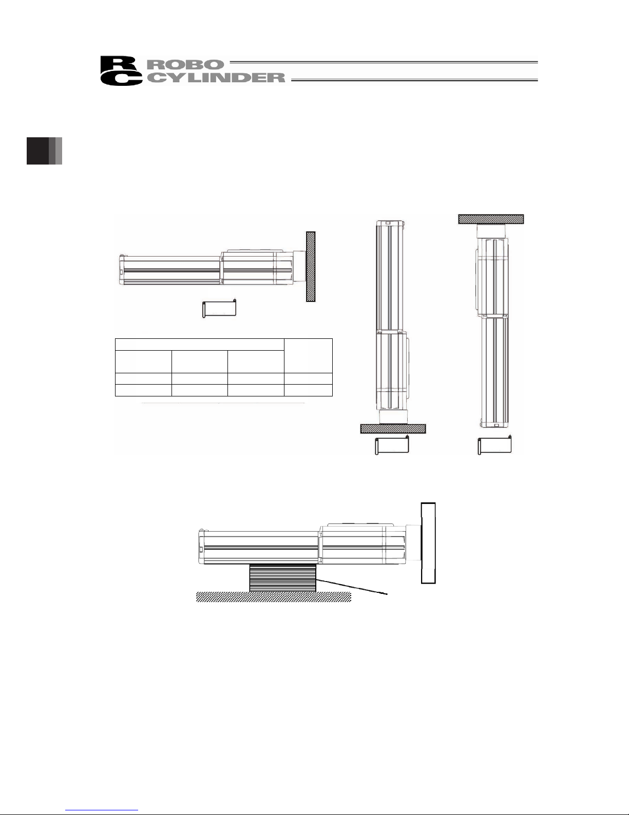
2. Installation
54
[Caution at Pressing]
Pay attention to the following when installation is conducted with using the attachment holes on the
reversing bracket.
Do not attempt to use only the attachment holes on the reversing bracket for installation.
Avoid external force to be applied on the main body.
Some operational conditions and conditions of installation environment could generate vibration,
which may cause operational error or parts malfunction.
Refer below for the availability of orientations for installation.
When using the product in horizontal or vertical orientation, have a support block to support the
main body to avoid any external force to be applied on the body.
Horizontal
Vertical
Ceiling
Mount
Installation Posture
Horizontal Vertical
Ceiling
Mount
Support
× × × No
{ {
× Yes
Support Block
Page 61

2. Installation
55
[4] Attachment of Transported Object
• There are tapped holes on the top surface of the slider. Affix the work part (transported object) here.
• The way to affix follows the installation of the main unit.
• There are two reamed holes on the top surface of the slider. Use these reamed holes if repeatability of
attaching and detaching is required. Also, if small tuning such as perpendicularity is required, use one
of the reamed holes for the tuning.
• Refer to the below table for the screwed depth and reamed depth. Screwing further than indicated in
the table may destroy the tapped hole or lower the reinforcement of the attachment of the work part,
result in the drop of the accuracy or an unexpected accident.
2-D
4-E
C
B
±0.02
A
Reamed Hole Pitch Tolerance: ±0.02
Mounting Bolt
Model Name A B C D E
Bolt Nominal Diameter Tightening Torque
SA4C
SA4R
20 24 32
I3H7 depth 6
M3 depth 7 M3 0.83N•m(0.085Kgf•m)
SA6C
SA6R
31 32 50
I5H7 depth 6
M5 depth 10 M5 3.42N•m(0.35Kgf•m)
SA7C
SA7R
39 32 50
I5H7 depth 10
M5 depth 10 M5 3.42N•m(0.35Kgf•m)
Tightening Screws
• Use hexagonal socket head bolts for the male threads for installing.
• Use of high-tension bolts meeting at least ISO 10.9 is recommended.
• Make sure to have the effective length of thread engagement at least approximately 1.8 times of the
nominal diameter of bolts and screws.
Caution: Pay attention when selecting the bolt length. Selection of inappropriate length of bolts
may cause a breakage of tapped holes or insufficient strength of attachment for
transportation.
Page 62

2. Installation
56
[5] Mounting Surface
• The platform to install the actuator should possess a structure that ensures enough stiffness, and
should be free from vibration.
• The surface where the actuator will be mounted should be a machined surface or that with an accuracy
equivalent to it, and the flatness should be 0.05mm/m or below.
• Ensure a room for maintenance work.
• The side and bottom surfaces of the base on the actuator work as the datum surfaces for the side of
the slider.
• Use these surfaces as the datum surfaces for mounting.
Datum surface
Datum surface
Datum surface effective area
Follow the below when installing the device using the datum surface.
Model Name A Dimensions [mm]
SA4C, SA4R,
SA6C, SA6R,
SA7C, SA7R
2 to 4 or less
R0.3 or less
Page 63

2. Installation
57
2.3.3 Vacuum of Cleanroom Type
Cleanroom type actuator realizes the performance complied with Cleanroom Class 10 (0.1ȝm) by
absorbing air from the vacuum joints. In the table below, shows the amount of absorbing as a reference
in the rated velocity for each model.
• Perform air absorbing from the two vacuum joint on the sides of the body with the amount of
absorbing (total of 2 places) described in the table below. Also, have the pipe layout to allocate equal
absorbing performance at the two joints.
• Use the system with all the attachment holes on the bottom of the body closed. The cleanliness
performance will drop if a through hole exists on the body.
[Reference for Amount of Absorbing]
Lead Amount of Absorbing
Model
[mm] Nl/min (L/min)
2.5 10 (11)
5 20 (22)
10 40 (43)
RCP5CR-SA4C
16 60 (65)
3 15 (16)
6 30 (32)
12 70 (76)
RCP5CR-SA6C
20 100 (108)
4 30 (32)
8 40 (43)
16 70 (76)
RCP5CR-SA7C
24 90 (97)
Page 64

3. Connecting with the Controller
58
3. Connecting with the Controller
As the connection cable for the controller and RCP5/RCP5CR (this actuator), use the IAI-dedicated
controller and dedicated connection cable.
This section explains the wiring method for a single axis.
• If the dedicated connection cable cannot be secured, reduce the load on the cable by allowing it to
deflect only by the weight of the cable or wire it in a self-standing cable hose, etc., having a large
radius.
• Do not cut and reconnect the dedicated connection cable for extension or shorten the cable.
• Do not pull on the dedicated connection cable or bend it forcibly.
• The actuator cable coming out of the motor unit is not meant to be bent. Fix the cable so it would not
be bent repeatedly
Please consult with IAI if you require a different kind of cable than the one supplied.
Page 65

3. Connecting with the Controller
59
Warning: For wiring, please follow the warnings stated below. When constructing a system as
the machinery equipment, pay attention to the wiring and connection of each cable
so they are conducted properly. Not following them may cause not only a malfunction
such as cable breakage or connection failure, or an operation error, but also electric
shock or electric leakage, or may even cause a fire.
• Use dedicated cables of IAI indicated in this instruction manual. Contact us if you wish to
have a change to the specifications of the dedicated cables.
• Make sure to turn the power off in the process of power line or cable connection or
disconnection.
• Do not attempt to cut a dedicated cable with connectors on both ends to extend, shorten or
re-joint it.
• Hold the dedicated cable to avoid mechanical force being applied to the terminals and
connectors.
• Use a cable pipe or duct to have an appropriate protection when there is a possibility of
mechanical damage on a dedicated cable.
• In case a dedicated cable is to be used at a moving part, make sure to lay out the cable
without applying any force to pull the connector or extreme bend on the cable. Do not attempt
to use the cable with a bending radius below the allowable value.
• Make certain that the connectors are plugged properly. Insufficient connection may cause an
operation error, thus it is extremely risky.
• Do not lay out the cables to where the machine runs over them.
• Pay attention to the cable layout so it would not hit peripherals during an operation. In case it
does, have an appropriate protection such as a cable track.
• When a cable is used hanging on the ceiling, prevent an environment that the cable swings
with acceleration or wind velocity.
• Make sure there is not too much friction inside the cable storage equipment.
• Do not apply radiated heat to power line or cables.
CB-CAN-MPAƑƑƑ, CB-CAN-MPAƑƑƑ-RB
• Do not bend the cable in the area from the connector tip inward to 150mm on both ends.
Motor • Encoder Integrated Cables CB-CAN-MPAƑƑƑ
Motor • Encoder Integrated Cables Robot Type CB-CAN-MPAƑƑƑ-RB
• Have a sufficient radius for bending, and avoid a bend concentrating on one point.
Steel Strap
(Piano Wire)
Tie them up softly.
Page 66

3. Connecting with the Controller
60
• Do not let the cable bend, kink or twist.
• Do not pull the cable with a strong force.
• Pay attention not to concentrate the twisting force to one point on a cable.
• Do not pinch, drop a heavy object onto or cut the cable.
• When a cable is fastened to affix, make sure to have an appropriate force and do not tighten
too much.
Do not use spiral tube in any
position where cables are bent
frequently.
Page 67

3. Connecting with the Controller
61
• PIO line, communication line, power and driving lines are to be put separately from each
other and do not tie them together. Arrange so that such lines are independently routed in the
duct.
Follow the instructions below when using a cable track.
• If there is an indication to the cable for the space factor in a cable track, refer to the wiring
instruction given by the supplier when storing the cable in the cable track.
• Avoid the cables to get twined or twisted in the cable track, and also to have the cables move
freely and do not tie them up. (Avoid tension being applied when the cables are bent.)
Do not pile up cables. It may cause faster abrasion of the sheaths or cable breakage.
Power line
I/O lines (flat cable)
Duct
Page 68

4. Maintenance and Inspection
62
4. Maintenance and Inspection
4.1 Inspection Items and Schedule
Follow the maintenance inspection schedule below.
It is assumed that the equipment is operating 8 hours per day.
If the equipment is running continuously night and day or otherwise running at a high operating rate,
inspect more often as needed.
Period of Time External visual inspection Internal inspection Greasing
(Note 1)
Start of work inspection
{
1 month inspection
{
3 month inspection
{
3 months after starting operation
6 months inspection
{
{
(Note 2)
Every 6 months thereafter
{
{
(Note 2)
Depends on grease
supply timing
(reference)
Note 1 Grease film may run out if the actuator is moved back and forth continuously over a distance of
30 mm or less. As a guide, perform a back-and-forth operation five times or so over a distance of
50 mm or more after a back-and-forth operation over such short distance has been repeated
5,000 to 10,000 times. This will restore oil film.
Note 2 Check the condition of grease, and wipe off the grease before supplying new in case it is
extremely dirty.
[Grease Supply Timing (Reference)]
Perform grease supply when it has reached to either the operation distance or spent months described in
the table below.
Grease Supply Timing (Reference)
Maximum Speed of Use [mm/s]
operated distance Months
0 to 750 or less 1,250 km
750 to 1440 2,500 km
12 month
Caution: • An actuator after 6 months of storage may have caused a degradation of the grease.
Supply grease before start using. [Refer to 4.6 “Grease Supply”]
• Degradation speed of grease may differ depending on the environment of use
(temperature, humidity and ambient conditions). It is recommended to shorten the
grease supply period if the actuator is used under a bad condition such as in high
temperature, high humidity or in dusty ambience.
Also, it is recommended to improve the environment conditions in case the grease
changes its color due to the bad condition of use.
Page 69

4. Maintenance and Inspection
63
4.2 External Visual Inspection
An external visual inspection should check the following things.
Main unit Loose actuator mounting bolts, other loose items
Cables Scratches, proper connections
Stainless steel sheet Scratches
Overall Irregular noise, vibration
• As a rule of thumb, the stainless steel sheet should last for about 5000km of slider motion.
However, under certain conditions, the stainless steel sheet may need to be replaced earlier.
Generally, replacing the stainless steel sheet will require that you bring the unit to our plant or have one
of our technicians come to your plant to perform the replacement.
• If the actuator is installed vertically, certain conditions may cause grease to drip from the guide. Please
ensure that proper cleaning is performed and grease is replenished.
4.3 Cleaning
• Clean exterior surfaces as necessary.
• Use a soft cloth to wipe away dirt and buildup.
• Do not blow too hard with compressed air as it may cause dust to get in through the gaps.
• Do not use oil-based solvents as they can harm lacquered and painted surfaces.
• To remove severe buildup, wipe gently with a soft cloth soaked in a neutral detergent or alcohol.
Page 70

4. Maintenance and Inspection
64
4.4 Internal Inspections
Turn OFF the power, remove the side cover and have a visual inspection.
When inspecting the interior, check the following items.
Main unit Loose mounting bolts, other loose items
Guide section Lubrication, buildup
Visually inspect the interior of the equipment. Check whether dust or other foreign matter has gotten
inside and check the lubrication state.
The lubrication may have turned brown. This is not a problem as long as the travel surfaces shine as
though they are wet.
If the grease is mixed with dust and does not have a shiny appearance, or if the grease has lost its
efficacy due to prolonged use, then clean each section and reapply grease.
The procedure for internal inspections is outlined below.
1) Loosen the screws on the side cover and detach the side cover.
2) Check inside.
3) After finishing the inspection, assemble back in the reverse order.
If you touch the edge of the stainless steel sheet in the attaching the side cover process, the sheet
may get damaged or wavy which result in shortening life or earlier wear-out.
To avoid touching the edge of the sheet, insert a spacer (approximatery 0.1 to 0.2mm) between the
sheet and cover to push up the sheet, and then push in the cover.
Also, make sure to follow the notice of caution when attaching side covers described in the next
page when side covers are attached.
When affixing the side cover, tighten the screws with the tightening torque described below.
Model Name Screw Diameter Tightening Torque
SA4C, SA4R,
SA6C, SA6R,
SA7C, SA7R
M3 41.4N•cm
Caution: When checking inside the equipment, be careful not to forcibly bend the stainless
steel sheet or scratch it.
Do not tug on the stainless steel sheet or in any way attempt to reposition it.
Change in the attached condition may cause the sheet to be mounted unevenly or
impact the product life. In such cases, please contact IAI Sales Engineer Department.
Keep in mind that the edges of the stainless steel sheet can cause injuries. Always
wear gloves when working on it.
Page 71

4. Maintenance and Inspection
65
Caution When Attaching Side Covers
Keep the dimension shown below for the opening when attaching the side covers.
Also, have the side covers attached in symmetry to the center line.
Model Name
SA4C
SA4R
SA6C
SA6R
SA7C
SA7R
Dimension for Opening [mm] 11.4±0.4 16±0.4 24±0.4
Caution: The side covers and slider may interfere if the side covers are not attached with the
dimension for the opening described above, or not in symmetry.
4.5 Internal Cleaning
• Use a soft cloth to wipe away dirt and buildup.
• Do not blow too hard with compressed air as it may cause dust to get in through the gaps.
• Do not use oil-based solvents, neutral detergent or alcohol.
Center Line
Side Cover
Page 72

4. Maintenance and Inspection
66
4.6 Grease Supply
4.6.1 What Grease to Use
[1] Standard Type
IAI uses the following grease in our plant.
Guide and Ball Screw Kyodo Yushi Multitemp LRL 3
Other companies also sell similar types of grease. For more detailed information, ask the supplier to find
an equivalent for you by telling them the name of the grease.
Warning: Never use any fluorine-based grease. Mixing with lithium-based grease with other
grease not only reduces the performance of the grease, it may even cause damage
to the actuator.
[2] Cleanroom Type
On the cleanroom type, the urea based grease that has great low particle-emission, stable torque
characteristics, brilliant lubrication and anti-dust effect equivalent to the lithium based grease is
applied. IAI uses the following grease in our plant.
Guide and Ball Screw
Kuroda
Precision
Industries
C Grease
Warning: ࣭Apply low particle-emission grease on Cleanroom Type Actuator. Particles may be
generated if standard grease is applied.
࣭Do not attempt to apply fluorine and lithium grease. Mixing with urea based grease
may lose the lubrication performance the grease originally has, which may result
in such cases as damaging the mechanical parts or causing a drop in the
cleanliness characteristics.
Page 73

4. Maintenance and Inspection
67
4.6.2 How to Apply Grease
1) Remove the screw and detach the side cover on either side, right or left.
The grease nipple will appear.
When the side cover on the other side has been detached, the other grease nipple also appears.
Motor Side
Opposite Side of the Motor
Side Cover
Attachment Screws
Side Cover
Attachment Screws
After removal of the side cover on
either side
Side Cover
Grease Nipple
There is one on the
other side.
Page 74

4. Maintenance and Inspection
68
2) Supply grease from the grease nipple on either side, using the grease gun.
Wipe off the grease before supplying new in case it is extremely dirty.
(Note) Grease can also be applied from the grease nipple on the other side.
When grease is applied from the grease nipple on either side, grease is supplied to the
ball screw and the guides on both sides.
(Note) Make sure to use a grease gun that is applicable for the grease nipple inlet diameter
shown below.
Grease Nipple Diameter
I3.5
Recommended Grease Gun Nozzle Supplier
HGP NZ3 NSK
Model Name
Amount of Grease Supply
(Reference)
SA4 0.5cc to 1.0cc
SA6, SA7 1.5cc to 2.0cc
Move the slider back and forth in the stroke range after supplying grease so it spreads out
evenly in the area.
x Confirm that the ball tracks on the ball screw and guide look glossy with oil of grease. Supply
grease again if it is not spread enough.
x Wipe off excess grease.
Caution: Supplying too much grease may increase sliding resistance and load to the motor,
resulting in a drop of performance.
Also, excess grease on the ball screw may be splashed around in the ambience.
Grease Gun
Page 75

4. Maintenance and Inspection
69
3) Attach the side covers after grease supply is finished.
If you touch the edge of the stainless steel sheet in the attaching process, the sheet may get
damaged or wavy which result in shortening life or earlier wear-out.
To avoid touching the edge of the sheet, insert a spacer (approximately 0.1 to 0.2mm) between
the sheet and cover to push up the sheet, and then push in the cover.
Also, make sure to follow the notice of caution when attaching side covers described in the next
page when side covers are attached.
When affixing the side cover, tighten the screws with the tightening torque described below.
Model Name Screw Diameter Tightening Torque
SA4C, SA4R,
SA6C, SA6R,
SA7C, SA7R
M3 41.4N•cm
Caution When Attaching Side Covers
Keep the dimension shown below for the opening when attaching the side covers.
Also, have the side covers attached in symmetry to the center line.
Model Name
SA4C
SA4R
SA6C
SA6R
SA7C
SA7R
Dimension for Opening [mm] 11.4±0.4 16±0.4 24±0.4
Caution: The side covers and slider may interfere if the side covers are not attached with the
dimension for the opening described above, or not in symmetry.
Caution: • Do not damage the stainless steel sheet by bending it forcefully during work.
Also you may get hurt on the edge of the stainless steel sheet. Wear gloves when
you work on it.
The front bracket is supporting the ball screw. Do not detach it.
If the front bracket iloses its tuned condition, it may cause an increase of driving
resistance, shortened life of each component or abnormal noise due to the center of
the axis being off the right position.
• In case the grease got into your eye, immediately go see the doctor to get
appropriate care.
After finishing the grease supply work, wash your hands carefully with water and
soap to rinse the grease off.
Center Line
Side Cover
Page 76

4. Maintenance and Inspection
70
4.7 Procedure for Stainless Steel Sheet Replacement and Adjustment
In this section, explains how to replace and adjust the stainless steel sheet.
The stainless steel sheet can be changed without removing the side cover.
4.7.1 Preparation
(1) Items required for replacing the stainless steel sheet
y Replacement stainless steel sheet
y Phillips screwdriver
y Adhesive tape
(2) Caution for the stainless steel sheet tension
Degradation and wear-out of the stainless steel sheet relies on its tension of attachment.
If the stainless steel sheet is pulled with a huge force and the gap between the sheet and the slider
cover is large, there is a risk of metal fatigue.
On the other hand, if the tensile strength is too low, the stainless steel sheet would interfere with the
back side of the slider cover and make dust to be generated.
(3) Names of the Parts
Stainless Steel Sheet Stainless Steel Sheet Retainer Plates
Stainless Steel Sheet Retainer Plates
Slider Cover
Page 77

4. Maintenance and Inspection
71
4.7.2 Procedure for Replacement and Tuning
Have a replacement and tuning in (1) Procedure 1 for RCP5-SA4.
For other models, have a replacement and tuning in either (1) Procedure 1 or (2) Procedure 2.
(1) Procedure 1
1) Remove the screws (4 places) holding the stainless steel sheet and stainless steel sheet retainer
plates (2 pieces) with using a Phillips screwdriver.
2) Pull the old stainless steel sheet till in front of the slider.
Make sure not to pull it out completely off the slider.
3) Join a new stainless steel sheet to the old one with using cellophane tape.
Join with
cellophane tape
Old stainless
steel sheet
New stainless steel
sheet
Pull it till in front
of the slider.
In front of Slider
Page 78

4. Maintenance and Inspection
72
4) Pull the old stainless steel sheet so the new one goes through below the slider. Pull it till the new
stainless steel sheet comes to the edge of the actuator.
5) Remove the old stainless steel sheet.
6) Fix the two stainless steel sheet retainer plates using the screws (four locations).
Use a Phillips screwdriver to attach it.
Tightening Torque
41.4Nycm
7) After the stainless steel sheet retainer plates have been fixed, move the slider from one side to
the other side (full stroke) with your hand to check that there is no rise or slackness in the
stainless steel sheet. If there is any problem, repeat from step 6).
Pull
Old stainless
steel sheet
New stainless steel
sheet
Pull till the
edge
Edge
There are two grooves for stainless steel
sheet attachment guides. Align so that the
stainless steel sheet is positioned at the
center between the two grooves.
Attach the stainless steel sheet so that it is
not bent.
Page 79

4. Maintenance and Inspection
73
(1) Procedure 2
1) Remove the screws (four locations) fixing the stainless steel sheet using a Phillips screwdriver
and remove the stainless steel sheet retainer plates (two plates).
2) Pull out the old stainless steel sheet.
3) Attach adhesive tape on one side of new stainless steel sheet.
Stainless Steel Sheet Stainless Steel Sheet
Adhesive tape
4) Put the stainless steel sheet with an adhesive tape on the side cover.
Attach adhesive tape so that it wraps around the end side of the stainless steel sheet. At
that time, arrange it so that about 3mm of the end of the tape projects from the stainless
steel sheet. Cut any tape excess.
Side Cover
Stainless Steel Sheet
Sheet end with adhesive tape
Take care not to drop the stainless steel sheet into the hole.
Page 80

4. Maintenance and Inspection
74
5) With the stainless steel sheet being held, move the slider to put through the stainless steel sheet.
6) After the stainless steel sheet passes through the slider, pull one end of the stainless steel sheet
out to the position of the stainless steel retainer plate.
Take off the adhesive tape once positioning is finished.
Page 81

4. Maintenance and Inspection
75
7) Fix the two stainless steel sheet retainer plates using the screws (four locations).
Use a Phillips screwdriver to attach it.
Tightening Torque
41.4Nycm
8) After the stainless steel sheet retainer plates have been fixed, move the slider from one side to
the other side (full stroke) with your hand to check that there is no rise or slackness in the
stainless steel sheet. If there is any problem, repeat from step 7).
There are two grooves for stainless steel
sheet attachment guides. Align so that the
stainless steel sheet is positioned at the
center between the two grooves.
Attach the stainless steel sheet so that it is
not bent.
Page 82

4. Maintenance and Inspection
76
4.8 Procedure for Belt Replacement and Tuning
Application : RCP4-SA4R, SA6R, SA7R
4.8.1 Inspection of the Belt
For inspection work, detach the pulley cover with phillips screwdriver and carry it out by visual.
The period of replacement for the deceleration belt cannot be clearly defined as the durability of it is
impacted so much by the operational conditions.
In generally speaking, it possesses bending life of several million times.
The timing belt gets worn away as the time passes, and it is necessary to have replacement at regular
intervals with the following conditions as reference.
yWhen the gear and belt area show obvious friction.
yWhen swelling occurs as a result of oil adhesion.
yWhen damages such as a crack occurs on the belt gear and back side.
Also, for the toothed belt, it is recommended to set the interval of regular replacement cycle when in use
under high wire fatigue condition in high acceleration and deceleration because it is difficult to judge the
right timing for replacement by checking appearance or looseness of the wires strengthening the belt.
4.8.2 Belt to Use
IAI uses the following belt in our plant
Model
IAI Maintenance
Part Code
Manufacturer Model Code
SA4R TB-RCP5-SA4R 60S2M168R Rubber
STS Clean type (Bando Chemical Industries, Ltd.)
SA6R TB-RCP5-SA6R 60S2M208GB Rubbe
Super Torque G Bare-back type
(Mitsuboshi belting Ltd. )
SA7R TB-RCP5-SA7R 100S3M243R Rubber
STS Clean type (Bando Chemical Industries, Ltd.)
Pulley Cover
Bolt
Page 83

4. Maintenance and Inspection
77
4.8.3 Belt Replacement
[Items required for replacing the motor]
y Belt for Replacement
y Phillips Screwdriver
y Hexagon Wrench 2.5mm(SA4R/SA6R) or 3mm(SA7R)
y Tension Gauge (that is available for pulling with 80N)
y Long Tie-Band (thin string)
[Procedure]
1) Remove the three bolts holding the pulley cover with a Phillips screwdriver, and detach the
pulley cover.
2) Loosen the four bolts holding the pulley on the motor side with a 2.5mm-sized (for SA4R/SA6R)
or 3mm-sized (for SA7R) hex wrench.
Replace the belt if it is necessary.
Pulley Cover
Bolt
Bolt
Belt
Page 84

4. Maintenance and Inspection
78
3) Adjust the belt tension.
Hang a tie-band (thin string) on the end of the motor unit and pull it in specified load (specified
tensile strength) with a tension gauge.
Once the load reached the specified, tighten the bolts with a 2.5 mm-sized (for SA4R/SA6R) or
3mm-sized (for SA7R) hex wrench to affix.
4) Tighten the three bolts holding the pulley cover with a Phillips screwdriver to attach the pulley
cover.
Model Name Tightening Torque
SA4R, SA6R 43.1Nycm
SA7R 76.8Nycm
Belt Tensile Strength
SA4R 20 to 25N
SA6R 25 to 30N
SA7R 80 to 90N
SA4R, SA6R Tightening Torque : 152Nycm
SA7R Tightening Torque : 323Nycm
Bolt
Belt Tensile
Strength
Pulley Cover
Bolt
Tie-Band (thin string)
Belt Tensile Strength
Page 85

4. Maintenance and Inspection
79
4.9 Motor Replacement Process
4.9.1 SA4C, SA6C, SA7C
[Items required for replacing the motor]
y Motor Unit for Replacement
y Hex wrench set 2mm-sized or 2.5mm-sized
[Procedure]
1) Remove the screw affixing the actuator and the motor unit with a 2mm-sized (SA4C, SA6C),
2.5mm-sized (SA7C) hex wrench.
2) Detach the motor unit.
For Fixed screws actuator and
Motor Unit
Page 86

4. Maintenance and Inspection
80
3) Make the profiles on the actuator side and motor unit side aligned so the projection matches to
the slit.
4) Attach the motor unit for replacement with the projection being matched with the slit.
5) Tighten the fixing screw to affixing the motor unit to the actuator with a 2mm-sized (SA4C, SA6C),
2.5mm-sized (SA7C) hex wrench.
Model Name Tightening Torque
SA4C, SA6C 167Nycm
SA7C 353Nycm
6) For Battery-less Absolute Type (Model Code WA), make sure to have a home-return operation on
the PC or touch panel teaching after the motor replacement.
Make the projection and slit
matched with each other.
Apply grease to the coupling part.
NOXLUB TL1010 grease made by NOK
Page 87

4. Maintenance and Inspection
81
4.9.2 SA4R, SA6R, SA7R
[Items required for replacing the motor]
y Motor Unit for Replacement
y Hexagon Wrench Set 2mm-sized
2.5mm-sized
[Procedure]
1) Remove the screw affixing the actuator and the motor unit with a 2mm-sized (SA4R, SA6R),
2.5mm-sized (SA7R) hex wrench.
SA4R
fixing screw to affixing is side, SA6R, SA7R fixing screw to affixing is top.
SA4R (View from side) SA6R, SA7R (View from top)
2) Detach the motor unit.
For Fixed screws actuator
and Motor Unit
Page 88

4. Maintenance and Inspection
82
3) Make the profiles on the actuator side and motor unit side aligned so the projection
matches to the slit.
4) Attach the motor unit for replacement with the projection being matched with the slit.
5) Tighten fixing screw to affixing the motor unit to the actuator with a 2mm-sized (SA4R, SA6R),
2.5mm-sized (SA7R) hex wrench.
SA4R (View from side) SA6RࠊSA7R (View from top)
Model Name Tightening Torque
SA4R, SA6R 167Nycm
SA7R 353Nycm
Make the projection and slit matched
with each other.
Apply grease to the coupling part.
NOXLUB TL1010 grease made by NOK
For Fixed screws actuator
and Motor Unit
Page 89

5. External Dimensions
83
5. External Dimensions
5.1 RCP5-SA4C
M.E: Mechanical End
S.E: Stroke End
CJB
CJL
CJT
CJR
41.5
22
Battery-less Absolute :145 (176 With Brake)
Battery-less Absolute :123 (154 With Brake)
12
4.5
1
Cable eject direction changed (Option)
L(Battery-less
Absolute)
Mass [kg]
Stroke
w/o
Brake
With
Brake
A B C D E F G H J K M
w/o
Brake
With
Brake
50 297 328 50 35 25 0 50 8 㸫 50 134 173 6 1.0 1.2
100 347 378 100 85 50 0 100 8 1 50 184 223 6 1.1 1.3
150 397 428 100 85 50 1 50 10 1 100 234 273 6 1.2 1.4
200 447 478 200 185 50 1 100 10 2 50 284 323 8 1.3 1.5
250 497 528 200 185 50 2 50 12 2 100 334 373 8 1.3 1.5
300 547 578 300 285 50 2 100 12 3 50 384 423 10 1.4 1.6
350 597 628 300 285 50 3 50 14 3 100 434 473 10 1.5 1.7
400 647 678 400 385 50 3 100 14 4 50 484 523 12 1.6 1.8
450 697 728 400 385 50 4 50 16 4 100 534 573 12 1.7 1.9
500 747 778 500 485 50 4 100 16 5 50 584 623 14 1.8 2.0
(Note) L dimensions described in the table are those with no cable ejection direction (option).
For cable ejection direction types (option), the dimensions are longer in 21mm.
12 36
8.5
9
26.5
40
48
slider top surface
(1)
15
25
1
39
Moment
datum point
X
12
3
Stroke
1
56 pay attention to
interference for 56 and more
35
3
76
K
L
M3 depth 4 (same on opposite side)
(for earth connection)
24
5
S.E.M.E.
M.E.
Home
(56)
Secure at least 100
9
24
±0.02
32
40
20 (pitch between φ3H7 holes ±0.02)
2-φ3H7 reamed depth 6
25
4-M3 depth 7
Pay attention to interference to slider mounted object
B (reamed hole and oblong hole)
17
A (reamed hole pitch)
17
J8
2-φ3H7 reamed depth 4
50
H
C
50
(when 50st)
G×100 (M4 hole pitch)
M-M4 through
(bolt screwing depth should be 6mm max.)
F-φ
3.4 through
φ
6.5 counterbore, depth 3.5 (from other side)
20
12
20
D ×100E
Oblong depth 4
Y
40
49
19.8
4
3
+0.010
0
(R1.5)
Detail diagram Y
Scale 2 : 1
3.52.5
φ 6.5
φ 3.4
6.3
Detail diagram X
Scale 1 : 1
Datum surface
(5)
Battery-less Absolute: 124(155 with brake)
Page 90

5. External Dimensions
84
5.2 RCP5-SA6C
M.E: Mechanical End
S.E: Stroke End
CJT
CJRCJL
CJB
2214.5
3.25 41.5
4.4
4.75
Cable eject direction changed (Option)
Battery-less Absolute :131.5 (172 With Brake)
Battery-less Absolute :110.5 (150 With Brake)
L(Battery-less
Absolute)
Mass [kg]
Stroke
w/o
Brake
With
Brake
A B C D E F G H J K
w/o
Brake
With
Brake
50 323 362.5 0 0 1 4 0 4 0 2 172 210.5 1.7 1.9
100 373 412.5 100 85 1 4 0 6 1 3 222 260.5 1.8 2.0
150 423 462.5 100 85 2 6 0 6 1 3 272 310.5 2.0 2.2
200 473 512.5 200 185 2 6 1 8 1 3 322 360.5 2.2 2.4
250 523 562.5 200 185 3 8 1 8 1 3 372 410.5 2.4 2.6
300 573 612.5 300 285 3 8 2 10 1 3 422 460.5 2.5 2.7
350 623 662.5 300 285 4 10 2 10 1 3 472 510.5 2.7 2.9
400 673 712.5 400 385 4 10 3 12 1 3 522 560.5 2.9 3.1
450 723 762.5 400 385 5 12 3 12 1 3 572 610.5 3.1 3.3
500 773 812.5 500 485 5 12 4 14 1 3 622 660.5 3.2 3.4
550 823 862.5 500 485 6 14 4 14 1 3 672 710.5 3.4 3.6
600 873 912.5 600 585 6 14 5 16 1 3 722 760.5 3.6 3.8
650 923 962.5 600 585 7 16 5 16 1 3 772 810.5 3.8 4.0
700 973 1012.5 700 685 7 16 6 18 1 3 822 860.5 3.9 4.1
750 1023 1062.5 700 685 8 18 6 18 1 3 872 910.5 4.1 4.3
800 1073 1112.5 800 785 8 18 7 20 1 3 922 960.5 4.3 4.5
(Note) L dimensions described in the table are those with no cable ejection direction (option).
For cable ejection direction types (option), the dimensions are longer in 20mm.
3
Stroke
13
3
8
44.5
110 37.5
(4.5)
L
M3 depth 6 (same on opposite side)
(for earth connection)
K
S.E.
Home M.E.
M.E.
16.5 46
1
17.5
57
58
10.5
62.5
Slider top surface
23
40
38.5
Moment
datum point
X
62.5
58
18.3
Secure at least 100
21
60
32
±0.02
50
2-φ5 H7 reamed depth 6
40
4-M5 depth 10
B (reamed hole and oblong hole)
10
65
(reamed hole pitch)
A
28
28
H-φ4 H7 reamed depth 5.5
E ×100
30C ×100
J
10
65
(M5 hole pitch)
F-M5 through
(bolt screwing depth should be 10mm max.)
D-φ4.5 through
φ8 counterbore, depth 4.5 (from other side)
9
G- oblong depth5.5
Y
4.55.5
5
φ4.5
φ8
Detail diagram X
Scale 1 : 1
Datum surface
4
+0.012
0
5
(R2)
Detail diagram Y
Scale 2 : 1
31 (pitch between φ5H7 holes ±0.02)
Battery-less Absolute: 112.5(152 with brake)
Page 91

5. External Dimensions
85
5.3 RCP5-SA7C
M.E: Mechanical End
S.E: Stroke End
CJB
CJRCJL
CJT
11
22
3
41.5
12
18
Battery-less Absolute :157
(207 With Brake)
Battery-less Absolute :135
(185 With Brake)
Cable eject direction changed (Option)
L(Battery-less
Absolute)
Mass [kg]
Stroke
w/o
Brake
With
Brake
A B C D E F G H J K
w/o
Brake
With
Brake
50 372 422 0 0 1 4 0 4 0 2 168 229 3.0 3.5
100 422 472 100 85 1 4 0 6 1 3 218 279 3.2 3.7
150 472 522 100 85 2 6 0 6 1 3 268 329 3.5 4.0
200 522 572 200 185 2 6 1 8 1 3 318 379 3.7 4.2
250 572 622 200 185 3 8 1 8 1 3 368 429 3.9 4.4
300 622 672 300 285 3 8 2 10 1 3 418 479 4.1 4.6
350 672 722 300 285 4 10 2 10 1 3 468 529 4.4 4.9
400 722 772 400 385 4 10 3 12 1 3 518 579 4.6 5.1
450 772 822 400 385 5 12 3 12 1 3 568 629 4.8 5.3
500 822 872 500 485 5 12 4 14 1 3 618 679 5.0 5.5
550 872 922 500 485 6 14 4 14 1 3 668 729 5.3 5.8
600 922 972 600 585 6 14 5 16 1 3 718 779 5.5 6.0
650 972 1022 600 585 7 16 5 16 1 3 768 829 5.7 6.2
700 1022 1072 700 685 7 16 6 18 1 3 818 879 5.9 6.4
750 1072 1122 700 685 8 18 6 18 1 3 868 929 6.1 6.6
800 1122 1172 800 785 8 18 7 20 1 3 918 979 6.4 6.9
(Note) L dimensions described in the table are those with no cable ejection direction (option).
For cable ejection direction types (option), the dimensions are longer in 14mm.
13
3
Stroke
3
(5)
72 pay attention to interference
for 56 and more
L
K
3
28.5
110 56
M3 depth 6 (same on opposite side)
(for earth connection)
M.E. M.E.
Home
S.E.
Secure at least 100
(72)
32
±0.02
50
20
60
48
2-φ5 H7 depth 10
4-M5 depth 10
Pay attention to interference to slider mounted object
B
(reamed hole and oblong hole)
J9
30
60
(reamed hole pitch)
A
30
60
(M5 hole pitch)
45C ×100
F-M5 depth 9
D-φ 6 through
φ 9.5 counterbore, depth 5.5 (from other side)
H-φ4 H7 reamed depth 6
40
40
E ×100
G- oblong depth 6
Y
17.5 46.5
1
64
slider top surface
13.5
26.5
72
73
30
48
53.5
(7)
Moment
datum point
X
21.3
71
73
5.5 5.5
5
φ 6
φ 9.5
Detail diagram X
Scale 1 : 1
Datum surface
5
4
+0.012
0
(R2)
Detail diagram Y
Scale 2 : 1
(7)
39 (pitch between
φ5H7 holes ±0.02)
Battery-less Absolute: 143(193 with brake)
Page 92

5. External Dimensions
86
5.4 RCP5CR-SA4C, RCP5-SA4C (Option Model SR)
* There is no pipe joint in Slider Roller Type (SR).
12 36
8.5
9
26.5
40
48
1
15
25
1
39
25
18.6
12
3
Stroke
(5)
1
35
3
76
φ
40
K
L
24
56 6
S.E.M.E.
M.E.
Home
Applicable Tube O. D.:φ6
56
9
24
±0.02
32
25
17
17
J8
50
H
C
20
12
20
D×100E
40
49
19.8
4
3
+0.010
0
R1.5
3.52.5
φ6.5
φ3.4
6.3
slider top surface
Datum surface
Moment
datum point
Detail diagram X
Scale 1 : 1
Joint Rotation Range
Oblong depth 4
50
(when 50st)
G×100 (M4 hole pitch)
B (reamed hole and oblong hole)
A (reamed hole pitch)
20 (pitch between
φ
3H7 holes ±0.02)
4-M3 depth 7
2-
φ
3
H7 reamed depth 6
Pay attention to
interference to slider
mounted object
Secure at least 100
Battery-less Absolute: 124(155 with brake)
56 pay attention to
interference for 56 and more
M3 depth 4 (same on opposite side)
(for earth connection)
2-
φ
3
H7 reamed depth 4
Detail diagram Y
Scale 2 : 1
M-M4 through
(bolt screwing depth should be 6mm max.)
F-
φ
3.4 through
φ
6.5 counterbore, depth 3.5 (from other side)
X
Y
M.E: Mechanical End
S.E: Stroke End
CJB
CJL
CJT
CJR
41.5
22
Battery-less Absolute :145 (176 With Brake)
Battery-less Absolute :123 (154 With Brake)
12
4.5
1
Cable eject direction changed (Option)
L(Battery-less
Absolute)
Mass [kg]
Stroke
w/o
Brake
With
Brake
A B C D E F G H J K M
w/o
Brake
With
Brake
50 297 328 50 35 25 0 50 8 㸫 50 134 173 6 1.0 1.2
100 347 378 100 85 50 0 100 8 1 50 184 223 6 1.1 1.3
150 397 428 100 85 50 1 50 10 1 100 234 273 6 1.2 1.4
200 447 478 200 185 50 1 100 10 2 50 284 323 8 1.3 1.5
250 497 528 200 185 50 2 50 12 2 100 334 373 8 1.3 1.5
300 547 578 300 285 50 2 100 12 3 50 384 423 10 1.4 1.6
350 597 628 300 285 50 3 50 14 3 100 434 473 10 1.5 1.7
400 647 678 400 385 50 3 100 14 4 50 484 523 12 1.6 1.8
450 697 728 400 385 50 4 50 16 4 100 534 573 12 1.7 1.9
500 747 778 500 485 50 4 100 16 5 50 584 623 14 1.8 2.0
(Note) L dimensions described in the table are those with no cable ejection direction (option).
For cable ejection direction types (option), the dimensions are longer in 21mm.
Page 93

5. External Dimensions
87
5.5 RCP5CR-SA6C, RCP5-SA6C (Option Model SR)
* There is no pipe joint in Slider Roller Type (SR).
X
Y
Battery-less Absolute: 112.5(152 with brake)
3
Stroke13
3
φ
40
8
44.5
110 37.5
4.5
L
K
15 15
S.E.
Home
M.E.
M.E.
16.5 46
1
17.5
57
58
10.5
62.5
23
40
38.5
18.9
30
62.5
58
18.3
21
60
32
±0.02
50
40
10
65
A
28
28
E×100
30C×100
J
10
65
9
4.55.5
5
φ4.5
φ8
4
+0.012
0
5
(R2)
slider top surface
Datum surface
Moment
datum point
Detail diagram X
Scale 1 : 1
Applicable Tube O. D.:φ6
Joint Rotation Range
G- oblong depth5.5
B (reamed hole and oblong hole)
4-M5 depth 10
31 (pitch between φ5H7 holes ±0.02)
2-φ5 H7 reamed depth 6
Secure at least 100
M3 depth 6 (same on opposite side)
(for earth connection)
(reamed hole pitch)
H-φ4 H7 reamed depth 5.5
(M5 hole pitch)
F-M5 through
(bolt screwing depth should be 10mm max.)
D-φ4.5 through
φ8 counterbore, depth 4.5 (from other side)
Detail diagram Y
Scale 2 : 1
M.E: Mechanical End
S.E: Stroke End
CJT
CJRCJL
CJB
2214.5
3.25 41.5
4.4
4.75
Cable eject direction changed (Option)
Battery-less Absolute :131.5 (172 With Brake)
Battery-less Absolute :110.5 (150 With Brake)
L(Battery-less
Absolute)
Mass [kg]
Stroke
w/o
Brake
With
Brake
A B C D E F G H J K
w/o
Brake
With
Brake
50 323 362.5 0 0 1 4 0 4 0 2 172 210.5 1.7 1.9
100 373 412.5 100 85 1 4 0 6 1 3 222 260.5 1.8 2.0
150 423 462.5 100 85 2 6 0 6 1 3 272 310.5 2.0 2.2
200 473 512.5 200 185 2 6 1 8 1 3 322 360.5 2.2 2.4
250 523 562.5 200 185 3 8 1 8 1 3 372 410.5 2.4 2.6
300 573 612.5 300 285 3 8 2 10 1 3 422 460.5 2.5 2.7
350 623 662.5 300 285 4 10 2 10 1 3 472 510.5 2.7 2.9
400 673 712.5 400 385 4 10 3 12 1 3 522 560.5 2.9 3.1
450 723 762.5 400 385 5 12 3 12 1 3 572 610.5 3.1 3.3
500 773 812.5 500 485 5 12 4 14 1 3 622 660.5 3.2 3.4
550 823 862.5 500 485 6 14 4 14 1 3 672 710.5 3.4 3.6
600 873 912.5 600 585 6 14 5 16 1 3 722 760.5 3.6 3.8
650 923 962.5 600 585 7 16 5 16 1 3 772 810.5 3.8 4.0
700 973 1012.5 700 685 7 16 6 18 1 3 822 860.5 3.9 4.1
750 1023 1062.5 700 685 8 18 6 18 1 3 872 910.5 4.1 4.3
800 1073 1112.5 800 785 8 18 7 20 1 3 922 960.5 4.3 4.5
(Note) L dimensions described in the table are those with no cable ejection direction (option).
For cable ejection direction types (option), the dimensions are longer in 20mm.
Page 94

5. External Dimensions
88
5.6 RCP5CR-SA7C, RCP5-SA7C (Option Model SR)
* There is no pipe joint in Slider Roller Type (SR).
Y
X
13
3
5
3
Stroke
(
φ
46)
L
K
3
28.5
7
110 56
15 15
M.E. M.E.S.E.
72
32
±0.02
50
20
60
48
2-φ5
B
J9
30
60
A
30
60
45C×100
H-φ4
H7 reamed depth 6
40
40
E×100
17.5 46.5
1
64
13.5
26.5
72
73
30
48
53.5
(7)
25.5
33
21.3
71
73
5.5 5.5
5
φ6
φ9.5
5
4
+0.012
0
(R2)
Detail diagram X
Scale 1 : 1
Datum surface
slider top surface
Moment
datum point
G- oblong depth 6
(reamed hole and oblong hole)
(M5 hole pitch)
(reamed hole pitch)
Home
4-M5 depth 10
39 (pitch between
φ
5H7 holes ±0.02)
H7 depth 10
Pay attention to interference
to slider mounted object
Secure at least 100
F-M5 depth 9
D-
φ
6 through
φ
9.5 counterbore, depth 5.5 (from other side)
M3 depth 6 (same on opposite side)
(for earth connection)
72 pay attention to interference
for 56 and more
Battery-less Absolute: 143(193 with brake)
Detail diagram Y
Scale 2 : 1
Applicable Tube O. D.:φ6
Joint Rotation Range
M.E: Mechanical End
S.E: Stroke End
CJB
CJRCJL
CJT
11
22
3
41.5
12
18
Battery-less Absolute :157
(207 With Brake)
Battery-less Absolute :135
(185 With Brake)
Cable eject direction changed (Option)
L(Battery-less
Absolute)
Mass [kg]
Stroke
w/o
Brake
With
Brake
A B C D E F G H J K
w/o
Brake
With
Brake
50 372 422 0 0 1 4 0 4 0 2 168 229 3.0 3.5
100 422 472 100 85 1 4 0 6 1 3 218 279 3.2 3.7
150 472 522 100 85 2 6 0 6 1 3 268 329 3.5 4.0
200 522 572 200 185 2 6 1 8 1 3 318 379 3.7 4.2
250 572 622 200 185 3 8 1 8 1 3 368 429 3.9 4.4
300 622 672 300 285 3 8 2 10 1 3 418 479 4.1 4.6
350 672 722 300 285 4 10 2 10 1 3 468 529 4.4 4.9
400 722 772 400 385 4 10 3 12 1 3 518 579 4.6 5.1
450 772 822 400 385 5 12 3 12 1 3 568 629 4.8 5.3
500 822 872 500 485 5 12 4 14 1 3 618 679 5.0 5.5
550 872 922 500 485 6 14 4 14 1 3 668 729 5.3 5.8
600 922 972 600 585 6 14 5 16 1 3 718 779 5.5 6.0
650 972 1022 600 585 7 16 5 16 1 3 768 829 5.7 6.2
700 1022 1072 700 685 7 16 6 18 1 3 818 879 5.9 6.4
750 1072 1122 700 685 8 18 6 18 1 3 868 929 6.1 6.6
800 1122 1172 800 785 8 18 7 20 1 3 918 229 6.4 6.9
(Note) L dimensions described in the table are those with no cable ejection direction (option).
For cable ejection direction types (option), the dimensions are longer in 14mm.
Page 95

5. External Dimensions
89
5.7 RCP5-SA4R
M.E.
* Dimension () is for brake-equipped
3
12
3
24
±0.02
32
40
25
76 20
30K
9
L
27
124(155)
M.E. S.E.
Z
12 36
15
25
1
48
8.5
26.5
9
39
48
40
97
(9)
2
6
26
28
X
32
32
4-M4 depth 9
10
20
12
C
D×10050 E
H 20
J8
17
17
Y
4
3
+ 0.010
0
(R1.5)
6.3
2.5 3.5
φ
3.4
φ6.5
24
5
View
diagram
Z
Scale 1 : 2
Datum surface
Detail diagram X
Scale 1 : 1
M3 depth 4 (same on opposite side)
(for earth connection)
Slider top surface
Moment
datum point
20 (pitch between φ3H7 holes ±0.02)
4-M3 depth 7
Stroke
Home
2-φ
3
H7 reamed depth 6
Secure at least 100
2-φ
3
H7 reamed depth 4
Detail diagram Y
Scale 2 : 1
M-M4 through
(bolt screwing depth should be 6mm max.)
F-
φ
3.4 through
φ6.5 counterbore, depth 3.5 (from other side)
B (reamed hole and oblong hole)
A (reamed hole pitch)
50
(when 50st)
G×100 (M4 hole pitch)
Oblong depth 4
M.E: Mechanical End
S.E: Stroke End
Mass [kg]
Stroke L A B C D E F G H J K M
w/o
Brake
With
Brake
50 188 50 35 25 0 50 8 - 50 134 158 6 1.3 1.5
100 238 100 85 50 0 100 8 1 50 184 208 6 1.4 1.6
150 288 100 85 50 1 50 10 1 100 234 258 6 1.5 1.7
200 338 200 185 50 1 100 10 2 50 284 308 8 1.6 1.8
250 388 200 185 50 2 50 12 2 100 334 358 8 1.6 1.8
300 438 300 285 50 2 100 12 3 50 384 408 10 1.7 1.9
350 488 300 285 50 3 50 14 3 100 434 458 10 1.8 2.0
400 538 400 385 50 3 100 14 4 50 484 508 12 1.9 2.1
450 588 400 385 50 4 50 16 4 100 534 558 12 2.0 2.2
500 638 500 485 50 4 100 16 5 50 584 608 14 2.1 2.3
Page 96

5. External Dimensions
90
5.8 RCP5-SA6R
M.E: Mechanical End
S.E: Stroke End
Mass [kg]
Stroke L A B C D E F G H J K
w/o
Brake
With
Brake
50 219 0 0 1 4 0 4 0 2 172 193 2.1 2.3
100 269 100 85 1 4 0 6 1 3 222 243 2.2 2.4
150 319 100 85 2 6 0 6 1 3 272 293 2.4 2.6
200 369 200 185 2 6 1 8 1 3 322 343 2.6 2.8
250 419 200 185 3 8 1 8 1 3 372 393 2.8 3.0
300 469 300 285 3 8 2 10 1 3 422 443 2.9 3.1
350 519 300 285 4 10 2 10 1 3 472 493 3.1 3.3
400 569 400 385 4 10 3 12 1 3 522 543 3.3 3.5
450 619 400 385 5 12 3 12 1 3 572 593 3.5 3.7
500 669 500 485 5 12 4 14 1 3 622 643 3.6 3.8
550 719 500 485 6 14 4 14 1 3 672 693 3.8 4.0
600 769 600 585 6 14 5 16 1 3 722 743 4.0 4.2
650 819 600 585 7 16 5 16 1 3 772 793 4.2 4.4
700 869 700 685 7 16 6 18 1 3 822 843 4.3 4.5
750 919 700 685 8 18 6 18 1 3 872 893 4.5 4.7
800 969 800 785 8 18 7 20 1 3 922 943 4.7 4.9
Page 97

5. External Dimensions
91
5.9 RCP5-SA7R
17.5 46.5
1
64
30
48
7
26.5
53.5
72
73
73
13.5
152.5
43
1
22
X
3
13
3
20
32
±0.02
50
60
48
110 42
K
L
38.5
43
31
Pay attention to interference
to slider mounted object
M.E.
M.E. S.E.
Z
30
60
A
45
30
C×100
60
E×100
J
9
40
40
Y
52
527
4
+
0.012
0
5
5
5.5 5.5
φ
6
φ
9.5
28.5
3
Datum surface
View diagram Z
Detail diagram X
Scale 1 : 1
M3 depth 6 (same on opposite side)
(for earth connection)
Scale 1 : 2
Slider top surface
Moment
datum point
(6.5)
G-Oblong depth 6
39 (pitch between φ5H7 holes ±0.02)
4-M5 depth 10
Stroke
Home
(72)
143(193)
Secure at least 100
2- φ5H7 reamed depth 10
4-M6 depth 13
B (reamed hole and oblong hole)
(reamed hole pitch)
H-φ4H7 reamed depth 6
D-φ6 through
F-M5 depth 9
φ9.5 counterbore, depth 5.5 (from other side)
(M5 hole pitch)
Detail diagram Y
Scale 2 : 1
(R2)
* Dimension () is for brake-equipped
M.E: Mechanical End
S.E: Stroke End
Mass [kg]
Stroke L A B C D E F G H J K
w/o
Brake
With
Brake
50 246 0 0 1 4 0 4 0 2 168 215 3.7 4.2
100 296 100 85 1 4 0 6 1 3 218 265 3.9 4.4
150 346 100 85 2 6 0 6 1 3 268 315 4.2 4.7
200 396 200 185 2 6 1 8 1 3 318 365 4.4 4.9
250 446 200 185 3 8 1 8 1 3 368 415 4.6 5.1
300 496 300 285 3 8 2 10 1 3 418 465 4.8 5.3
350 546 300 285 4 10 2 10 1 3 468 515 5.1 5.6
400 596 400 385 4 10 3 12 1 3 518 565 5.3 5.8
450 646 400 385 5 12 3 12 1 3 568 615 5.5 6.0
500 696 500 485 5 12 4 14 1 3 618 665 5.7 6.2
550 746 500 485 6 14 4 14 1 3 668 715 6.0 6.5
600 796 600 585 6 14 5 16 1 3 718 765 6.2 6.7
650 846 600 585 7 16 5 16 1 3 768 815 6.4 6.9
700 896 700 685 7 16 6 18 1 3 818 865 6.6 7.1
750 946 700 685 8 18 6 18 1 3 868 915 6.8 7.3
800 996 800 785 8 18 7 20 1 3 918 965 7.1 7.6
Page 98

6.Life
92
6. Life
The mechanical life of the actuator is represented by that of the guide receiving the greatest moment
load.Operation life of the linear guide is to be determined by the total driving distance which can reach
without having 90% flaking (peeling on rail surface).
Operation life can be figured out with the calculation method shown below.
6.1 How to Calculate Operaition Life
For the operation life of the linear guide, use the dynamic allowable moment stated in 1.2 Specifications,
and figure out with the formula below.
L =
࣭5000km
L : Operation life (km) C
M
: Allowable dynamic moment (N㺃m)
M : Moment to work (N㺃m) 5000km : Standard rated life of ROBO Cylinder
In addition, have a calculation for the drop of life with the formula below if there is a concern that the life
could drop due to the condition of vibration or way to be attached.
L = ࣭ ࣭ ࣭5000km
L : Operation life (km) C
M
: Allowable dynamic moment (N㺃m)
M : Moment to work (N㺃m) f
ws
: Standard operational coefficient
f
w
: Load coefficient fȘ : Attachment coefficient
5000km : Standard rated life of ROBO Cylinder
Explained below is regarding the standard operational coefficient f
ws
, load coefficient f
w
and attachment coefficient f
Ș.
Refer to the contents below to set them up.
[Standard operatinal coefficient f
ws
]
For ROBO Cylinders described in this manual, f
ws
= 1.2. It is a coefficient defined for each model, some
models such as RCS3 high-speed type is 1.35.
C
M
M
3
C
M
M
3
f
w
f
ws
1
f
Ș
Page 99

6. Life
93
[Load coefficient f
w
]
It is a coefficient to consider the life drop due to operational conditions.
Load coefficient f
w
Operation Condition
Reference for
acceleration/deceleration
1.0 to 1.5 Small vibration or impact in slow operation 1.0G or less
[Attachment coefficient f
Ș]
Attachment coefficient fȘ is a coefficient to consider the life drop due to the condition of actuator
attachment.
Attachment
coefficient f
Ș
1.0 1.2 1.5
Attachment in whole area Attachment on both ends Attachment on spots
Attached condition
* As the figures are those in common for each manual, they are not for RCP5 Slider Type.
Replace to figures for RCP5 Slider Type and select the attachment coefficient.
* Even when in attachment in whole area, and the actuator is seated in the whole length of the product,
select 1.2 or 1.5 for the attachment coefficient depending on the position of screw fixing.
* For attachment in whole area, use all of the tapped holes (counterbored holes) on the seat surface to fix.
6.2 Operation Life
The operation life depends on the moment to work.With light load, it will be longer than 5,000km, the
standard rated life. With no consideration of vibration and attachment condition, the operation life is
40,000km according to the calculation with formula in the previous page underassumption that 0.5 C
M
(half of dynamic allowable moment) of moment is applied on. It shows that it can be 8 times longer than
the standard rated life, which is 5,000km.
Page 100

7. Warranty
94
7. Warranty
7.1 Warranty Period
One of the following periods, whichever is shorter:
y 18 months after shipment from IAI
y 12 months after delivery to the specified location
y 2,500 hours of operation
7.2 Scope of the Warranty
Our products are covered by warranty when all of the following conditions are met. Faulty products
covered by warranty will be replaced or repaired free of charge:
(1) The breakdown or problem in question pertains to our product as delivered by us or our authorized
dealer.
(2) The breakdown or problem in question occurred during the warranty period.
(3) The breakdown or problem in question occurred while the product was in use for an appropriate
purpose under the conditions and environment of use specified in the instruction manual and catalog.
(4) The breakdown of problem in question was caused by a specification defect or problem, or by a
quality issue with our product.
Note that breakdowns due to any of the following reasons are excluded from the scope of warranty:
[1] Anything other than our product
[2] Modification or repair performed by a party other than us (unless we have approved such
modification or repair)
[3] Anything that could not be easily predicted with the level of science and technology available at
the time of shipment from our company
[4] A natural disaster, man-made disaster, incident or accident for which we are not liable
[5] Natural fading of paint or other symptoms of aging
[6] Wear, depletion or other expected result of use
[7] Operation noise, vibration or other subjective sensation not affecting function or maintenance
Note that the warranty only covers our product as delivered and that any secondary loss arising from a
breakdown of our product is excluded from the scope of warranty.
7.3 Honoring the Warranty
As a rule, the product must be brought to us for repair under warranty.
7.4 Limited Liability
(1) We shall assume no liability for any special damage, consequential loss or passive loss such as a
loss of expected profit arising from or in connection with our product.
(2) We shall not be liable for any program or control method created by the customer to operate our
product or for the result of such program or control method.
 Loading...