

Page 1

Body Height
INC Type: 68
3 Min.
Bottom Surface
of Pallet
Pallet
Top Surface of
Bearing Holder
Top Surface of
Body
RCP4 Stopper Cylinder
First Step Guide
Fourth Edition
Thank you for purchasing our product.
Make sure to read the Safety Guide and detailed Instruction Manual (DVD) included with the product in addition to
this First Step Guide to ensure correct use.
This Instruction Manual is original.
• Using or copying all or part of this Instruction Manual without permission is prohibited.
• The company names, names of products and trademarks of each company shown in the sentences are registered
trademarks.
Product Check
This product is comprised of the following parts if it is of standard configuration.
If you find any fault in the contained model or any missing parts, contact us or our distributor.
1. Parts (The option is excluded.)
No. Part Name Model Quantity Remarks
1
Stopper Cylinder Main
Body
Refer to “How to read the model plate”, “How to
read the model No.”.
1
Accessories
CB-CA-MPA□□□
CB-CA-MPA□□□-RB
For ST68E, ST615E
□□□ shows the cable length
(Example)
□□□ : 020 = 2 [m]
2 Motor • Encoder Cables
CB-CAN-MPA□□□
CB-CAN-MPA□□□-RB
1
For ST4525E
□□□ shows the cable length
(Example)
□□□ : 020 = 2 [m]
3 First Step Guide 1
4 Operation Manual (DVD) 1
5 Safety Guide 1
*1 Please refer to the wiring layout for the enclosed power supply and I/O cable.
2. How to read the model plate
3. How to read the model No.
(Note 1) This may be marked for the purpose of IAI.
It is not an ID to describe the model code.
Precautions in Handling
1. Handling of the Packed Product
Please concern the handling of the unit so you would not hit or drop it while carrying.
• If the shipping box is to be left standing, it should be in a horizontal position.
• Do not step or sit on the package.
• Do not place on the carton any heavy object that may cause the carton to deform, or an article whose
shape allows a load to be concentrated at one point.
2. Handling of the Unpacked Product
Do not attempt to hold the cable when carrying the actuator, or pull the cables to move the unit.
Installation and Storage • Preservation Environment
1. Installation Environment
Do not use this product in the following environment.
Generally speaking, it should be an environment where a worker can work without any protective gear.
Also make sure to keep enough work space necessary for maintenance.
• Location exposed to radiant heat from a huge heat source such as the heat treatment
• Location where the surrounding air temperature exceeds the range of 0 to 40°C
• Location where condensation occurs due to abrupt temperature changes
• Location where relative humidity exceeds 85%RH
• Location exposed to direct sunlight
• Location exposed to corrosive gases or combustible gases
• Location exposed to significant amount of dust, salt or iron powder (Outside of ordinary assembly plant)
• Location where water, oil (includes oil mist and cutting fluid) or chemical is splashed
• Location where the product main body receives vibration or hit impact
When using the product in any of the locations specified below, provide a sufficient shield.
• Place subject to electrostatic noise
• Location where exposed to the influence of strong electric or magnetic field
• Location where exposed to the influence of ultraviolet or radiant rays
2. Storage and Preservation Environment
• The storage and preservation environment should comply with the same standards as those for the
installation environment.
• In particular, when the machine is to be stored for a long time, pay close attention to environmental
conditions so that no dew condensation forms. Unless specially specified, moisture absorbency protection
is not included in the package when the machine is delivered. In the case that the machine is to be stored
and preserved in an environment where dew condensation is anticipated, take the condensation
preventive measures from outside of the entire package, or directly after opening the package.
• For storage and preservation temperature, the machine withstands temperatures up to 60°C for a short
time, but in the case of the storage and preservation period of 1 month or more, control the temperature to
50°C or less.
• Storage and preservation should be performed in the horizontal condition. In the case it is stored in the
packaged condition, follow the posture instruction if any displayed on the package.
Names of the Parts
[ST4525E]
Rod
A
nti-Rotation Feature
Motor Cover
Connector
Protection cap
Bearing Holder
Main Body
Bottom Cover
[ST68E, ST615E]
Installation Flange
Lever
Lever Lock Bracket
Rod
Top C ove r
Main Body
Actuator Cable
Motor Cover
Rod Anti - Rotation Feature
Hole Plug
Hole Plug
End Roller
Please refer to the Catalog or the Instruction Manual (DVD) for the dimensions and profile.
Attachment
Refer to the Instruction Manual (DVD) for the attachments of the actuator and loads.
[Precautions for Attachments]
No. Item Precautions
1 Attachment
• In installation posture, only vertical mount is available. Cannot be mounted
vertically, horizontally oriented on the wall or on the ceiling.
• Utilize the attachment holes provided on the attachment plate for the attachment of
the unit.
For the size of tightening screws, use M5 for counterbore type, M6 for
tapped type (option) of ST4525E, and M8 screws for ST68E and ST615E.
• For installation of the main body of ST4525E, it is available to mount from the top
for the counterbore type and from the top
and bottom, two ways, for tapped type
(option).
For installation, make sure to have the
distance from the bottom side of the pallet
to the top side of the bearing holder 3mm or
more as shown in the figures below.
Distance less than 3mm may cause
problems in stopping pallet or smooth
control of transportation.
• The ST68E and ST615E units can be
mounted in 2 ways, one from the top
surface of the attachment plate while the
other is from the bottom.
However, make sure the dimension from
the bottom surface of the pallet to the top
of the attachment plate is as shown in
the figure on the right.
Not following this may cause the pallet to
stop or the transportation may not be
carried out smoothly (by causing the
pallet to overrun or to be pushed up).
• Ensure a room for maintenance work.
2 Screws to
be used
• For the bolts to be used, a high-tensile bolt complying with ISO-10.9 or more is
• Make sure to have the effective length of screw engagement described below or more
for the tightening of a bolt and a female screw.
If female screw in steel → thread length same as nominal diameter
If female screw in aluminum→thread length 1.8 times longer than nominal diameter
RCP4
- ST68E - I - 42P - N - 30 – P3 - S - L - * *
<Series name>
<Type>
ST4525E
45mm Width 25kg Type
ST68E
60mm Width 80kg Type
ST615E
60mm Width 150kg Type
<Encoder Type>
I : Incremental
<Motor Type>
28P : 28□ Size(ST4525E)
42P : 42□ Size(ST68E/ST615E)
<Deceleration Ratio>
N : Unspecified
<Stroke>
20 : 20mm (ST4525E)
30 : 30mm (ST68/ST615E)
<Identification for IAI use only>
(Note 1)
<Option>
CO : Specifications for Protection Cover
Type
CJT : Difference in Cable
Orientation (Rear side)
CJL : Difference in Cable
Orientation (Left side)
CJR : Difference in Cable
Orientation (Right side)
CJB : Difference in Cable
Orientation (Front side)
NM : Reversed-home type
DCT : D-cut Shaft Tip Type (Front side)
(ST4525E)
DCL : D-cut Shaft Tip Type (Left side)
(ST4525E)
DCR : D-cut Shaft Tip Type (Right side)
(ST4525E)
DCB : D-cut Shaft Tip Type (Rear side)
(ST4525E)
AHT : Attachment Hole on Body Front
Side (Motor Opposite Side)
= Tapped Hole Type
(φ9 counter bored hole for standard
type) (ST4525E)
<Cable Length>
N : Without Brake
P : 1m
S : 3m
M : 5m
X□□ : Specified Length
R□□ : Robot Cable
<Controller>
P3 : PSEP, MSEP, PCON-CA
Model
Serial numbe
r
MODEL RCP4-ST68E-I-42P-N-30-P3-S-L
SERIAL No. 000049893 MADE IN JAPAN
Warning : Operation of this equipment requires detailed installation and operation instructions which are
provided on the DVD Manual included in the box this device was packaged in. It should be retained
with this device at all times.
A hardcopy of the Manual can be requested by contacting your nearest IAI Sales Office listed at
the back cover of the Instruction Manual or on the First Step Guide.
•
Make sure to hold the main body part when handling the unpackaged actuator.
• When carrying the actuator, exercise caution not to bump it against nearby objects
or structures.
• Do not give any excessive force to any of the sections in the actuator.
Pallet
87mm
Bottom of Pallet
Top of Attachment
Frame
Page 2
Connection Diagram
For the controller, only the dedicated controller manufactured by our company can be used.
Using other controllers may cause a problem such as burning the product, ignition or generating heat.
Use the dedicated cable enclosed in the package when connecting the actuator and the controller.
[ST4525E]
Dedicated Connection Cable
Dedicated Controller
MSEP Controller
PCON-CA Controller
Robot Cable
: 5 mm or less r = 68 mm or more (Movable Use)
: more than 5m r = 73 mm or more (Movable Use)
Standard Cable
: 5 mm or less r = 85 mm or more (Fixed Use)
: more than 5m r = 91 mm or more (Fixed Use)
Dedicated connection cable
Motor encoder cable CB-CAN-MPA□□□,
Motor encoder robot cable CB-CAN-MPA□□□-RB
*) □□□ indicates the cable length. Up to 20m can be specified.
Example) 080 = 8m
[ST68E, ST615E]
Dedicated connection cable
MSEP controller
PSEP controller
PCON-CA controller
Dedicated connection cable
Power supply•I/O cable : Standard cable CB-CA-MPA□□□
*) □□□ indicates the cable length. Up to 20m can be specified.
Example) 080 = 8m
Robot cable CB-CA-MPA□□□-RB
L: 3m or more
L: 3m
r=80mm or more (Movable Use)
r=68mm or more (Movable Use)
L: 3m or more
L: 3m
Standard Cable
Robot Cable
r=85mm or more (Fixed Use)
r=91mm or more (Fixed Use)
r
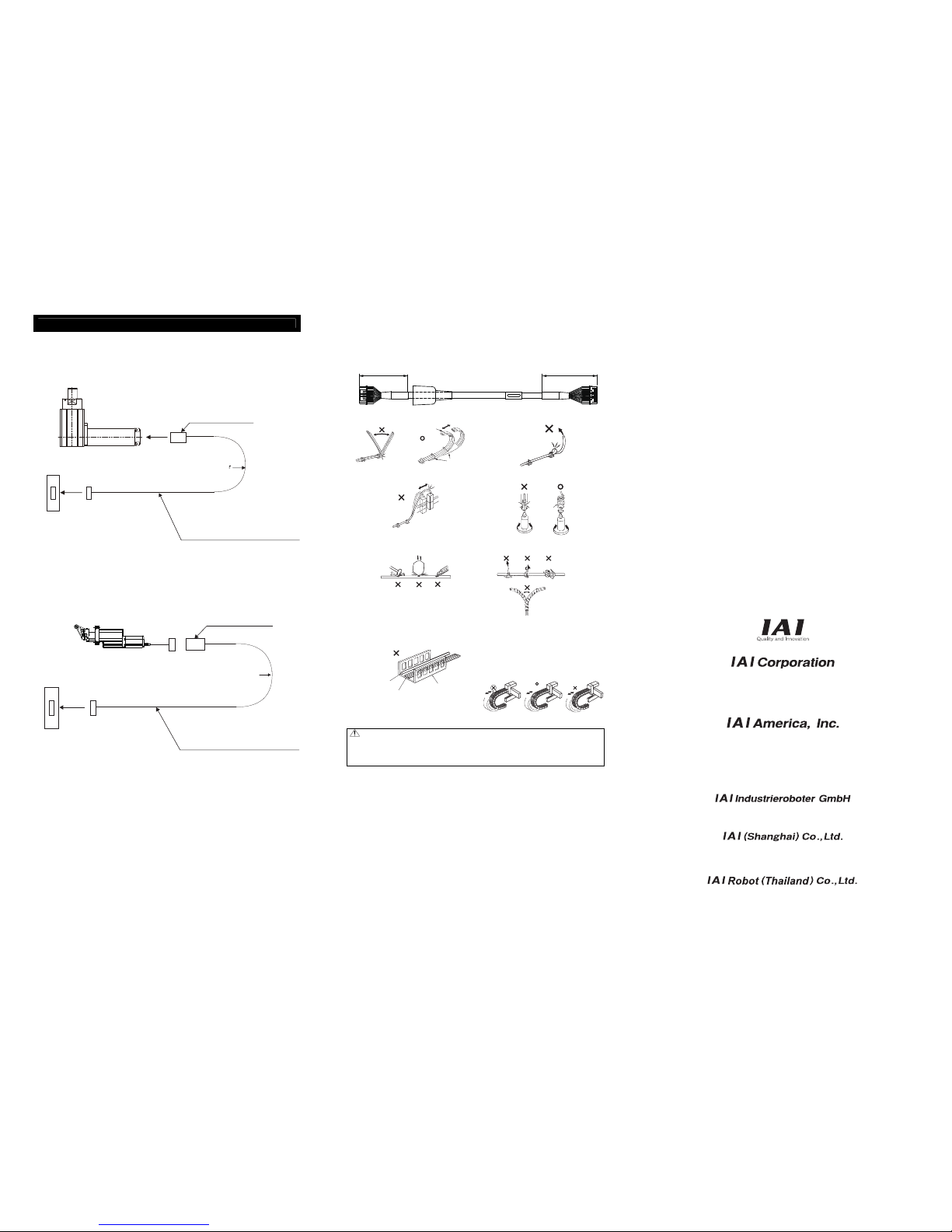
[Prohibited Items in the Cable Processing]
• Do not pull or bend forcibly the cable so as not to give any extra load or tension to the cable.
• Do not process the cable for extension or shortening by means of cutting out, combination or connecting with another
cable.
• Do not bend the cable in the area from the connector end inward to 150mm on both ends.
Standard cable : CB-CA-MPA□□□, CB-CAN-MPA□□□
Robot cable : CB-CA-MPA□□□-RB, CB-CAN-MPA□□□-RB
150mm 150mm
Note:
• When the cable is connected or disconnected, make sure to turn off the power to the controller. When the cable is
connected or disconnected with the controller power turned ON, it might cause a malfunction of the actuator and result in
a serious injury or damage to the machinery.
• When the connector connection is not correct, it would be dangerous because of a malfunction of the actuator. Make sure
to confirm that the connector is connected correctly.
Head Office: 577-1 Obane Shimizu-KU Shizuoka City Shizuoka 424-0103, Japan
TEL +81-54-364-5105 FAX +81-54-364-2589
website: www.iai-robot.co.jp/
Ober der Röth 4, D-65824 Schwalbach am Taunus, Germany
TEL 06196-88950 FAX 06196-889524
SHANGHAI JIAHUA BUSINESS CENTER A8-303, 808, Hongqiao Rd. Shanghai 200030, China
TEL 021-6448-4753 FAX 021-6448-3992
website: www.iai-robot.com
Technical Support available in USA, Europe and China
Head Office: 2690 W. 237th Street, Torrance, CA 90505
TEL (310) 891-6015 FAX (310) 891-0815
Chicago Office: 110 East State Parkway, Schaumburg, IL 60173
TEL(847) 908-1400 FAX (847) 908-1399
TEL (678) 354-9470 FAX (678) 354-9471
website: www.intelligentactuator.com
Atlanta Office: 1220 Kennestone Circle, Suite 108, Marietta, GA 30066
825 PhairojKijja Tower 12th Floor, Bangna-Trad RD., Bangna, Bangna, Bangkok 10260, Thailand
TEL +66-2-361-4458 FAX +66-2-361-4456
• Do not let the cable flex at a single point.
Steel Strap
(Piano Wire)
Tie them up softly.
•
Do not let the cable bend, kink or twist.
• Do not pull the cable with a strong force.
•
Do not let the cable receive a turning force at a single
point.
• Do not pinch, drop a heavy object onto or cut the cable.
•
When fixing the cable, provide a moderate slack and do
not tension it too tight.
Do not use spiral tube in any
position where cables are bent
frequently.
• Separate the I/O line, communication line and power
line from each other.
Arrange so that such lines are independently routed in
the duct.
Power Line
Duct
I/O Line
(Flat Cable, etc.)
Follow the instructions below when using a cable track.
• If there is an indication to the cable for the space factor
in a cable track, refer to the wiring instruction given by
the supplier when storing the cable in the cable track.
• Avoid the cables to get twined or twisted in the cable
track, and also to have the cables move freely and do
not tie them up. (Avoid tension being applied when the
cables are bent.)
Do not pile up cables. It may cause faster abrasion of
the sheaths or cable breakage..
Manual No.: ME0293-4A
 Loading...