

Page 1

ROBO Cylinder
Slider Type
RCP2 Actuators
Motor Straight Type: SA5C, SA6C, SA7C, SS7C, SS8C, HS8C
Motor Reversing Type: SA5R, SA6R, SA7R, SS7R, SS8R, HS8R
RCP2CR Actuators, Cleanroom Specification
SA5C, SA6C, SA7C, SS8C, HS8C
Operating Manual
First Edition
IAI America Inc.
Page 2

Page 3

Note
Greasing Actuators of Cleanroom Specification
For ROBO Cylinder actuators of cleanroom specification, use grease of low-dust-raising
type for cleanroom applications.
The grease specified in the maintenance/inspection sections of the Operating Manual is for
actuators of standard specification.
Using the grease for the standard actuators on the cleanroom actuators may generate dust.
Recommended grease:
C Grease by Kuroda Precision Industries Ltd.
C Grease by Kuroda Precision Industries is applied to the cleanroom actuators before
shipment from IAI.
Page 4

Safety Precautions (Please read before using the product.)
Before installing, operating, maintaining or inspecting this product, please peruse this operating manual as well
as the operating manuals and other related documentations for all equipment and peripheral devices
connected to this product in order to ensure the correct use of this product and connected equipment/devices.
Those performing installation, operation, maintenance and inspection of the product must have sufficient
knowledge of the relevant equipment and their safety. The precautions provided below are designed to help
you use the product safely and avoid bodily injury and/or property damage.
In this operating manual, safety precautions are classified as “Danger,” “Warning,” “Caution” and
“Note,” according to the degree of risk.
Danger
Failure to observe the instruction will result in an imminent danger leading to death or
serious injury.
Warning
Failure to observe the instruction may result in death or serious injury.
Caution
Failure to observe the instruction may result in injury or property damage.
Note
The user should take heed of this information to ensure the proper use of the product,
although failure to do so will not result in injury.
It should be noted that the instructions under the
Caution
and
Note
headings may also
lead to serious consequences, if unheeded, depending on the situation.
All instructions contained herein provide vital information for ensuring safety. Please read the contents
carefully and handle the product with due caution.
Please keep this operating manual in a convenient place for quick reference whenever needed, and also make
sure that the manual will get to the end-user.
● Do not use this product for the following applications:
1. Medical equipment used to maintain, control or otherwise affect human life or physical health
2. Mechanisms and machinery designed for the purpose of moving or transporting people
3. Important safety parts of machinery
This product has not been planned or designed for applications requiring high levels of safety. Use of this
product in such applications may jeopardize the safety of human life. The warranty covers only the product
as it is delivered.
● Do not use this product in a place exposed to ignitable, inflammable or explosive substances. The product
may ignite, burn or explode.
Danger
General
Installation
Page 5

2
● When installing the product, make sure to securely support and affix it (including the work). Failure to do
so may cause the product to tip over, drop or malfunction, resulting in injury.
● Avoid using the product in a place where the main unit or controller may come in contact with water or oil
droplets.
● Never cut and/or reconnect the cables supplied with the product for the purpose of extending or
shortening the cable length. Doing so may result in fire.
● Do not enter the machine’s range of operation while the product is operating or standing by. The actuator
may move suddenly, causing injury.
● Do not pour water onto the product. Spraying water over the product, washing it with water or using it in
water may cause the product to malfunction, resulting in injury, electric shock, fire, etc.
● Never modify the product. Unauthorized modification may cause the product to malfunction, resulting in
injury, electric shock, fire, etc.
● Do not disassemble and reassemble the components relating to the basic structure of the product or its
performance and function. Doing so may result in injury, electric shock, fire, etc.
● Do not use the product outside the specifications. Using the product outside the specifications may cause
it to fail, stop functioning or sustain damage. It may also significantly reduce the service life of the product.
In particular, observe the maximum loading capacity and speed.
● If the machine will stop in the case of system problem such as emergency stop or power failure, design a
safety circuit or other device that will prevent equipment damage or injury.
● Make sure to provide Class D grounding for the controller and actuator (formerly Class 3 grounding:
Grounding resistance at 100 Ω or less). Leakage current may cause electric shock or malfunction.
● Before supplying power to and operating the product, always check the operation area of the equipment to
ensure safety. Supplying power to the product carelessly may cause electric shock or injury due to contact
with the moving parts.
● Wire the product correctly by referring to the operation manual. Securely connect the cables and
connectors so that they will not be disconnected or come loose. Failure to do so may cause the product to
malfunction or cause fire.
● Before operating the moving parts of the product by hand (for the purpose of manual positioning, etc.),
confirm that the servo is turned off (using the teaching pendant). Failure to observe this instruction may
result in injury.
● Do not scratch the cables. Scratching, forcibly bending, pulling, winding, crushing with heavy object or
Operation
Warning
General
Installation
Operation
Maintenance, Inspection, Repair
Page 6

pinching a cable may cause it to leak current or lose continuity, resulting in fire, electric shock, malfunction,
etc.
● Turn off the power to the product in the event of power failure. Failure to do so may cause the product to
suddenly start moving when the power is restored, thus resulting in injury or product damage.
● If the product is generating heat, smoke or a strange smell, turn off the power i mmediately. Continuing to
use the product may result in product damage or fire.
● If noise or abnormally high vibration is detected, stop the operation immediately. Continuing to use the
product may result in product damage, malfunction due to damage, runaway machine, etc.
● If any of the product’s protective functions (alarms) has actuated, turn off the power immediately.
Continuing to use the product may result in injury due to product malfunction, or cause product breakdown
or damage. After the power has been cut off, identify and remove the cause of the problem, and then
reconnect the power.
● Do not step on the product, use it as a footstool or place any object on it. You may slip and fall or the
product may tip over or drop, resulting in injury. Malfunction, runaway product, etc., may also result due to
product breakdown or damage.
● Before commencing maintenance/inspection, servicing, replacement or any other work on the product,
make sure to completely cut off the power supply to the product. Also take heed of the following
precautions:
1. Put up a sign bearing “WORK IN PROGRESS. DO NOT TURN ON POWER” or other warning
statement to that effect, to prevent a bystander from accidentally turning on the power.
2. If multiple operators work together to perform maintenance/inspection work, the operators should
always give verbal cues to one another to ensure safety before turning on/off the power or moving
any axis.
● Do not throw the product into flames. The product may explode or toxic gases may generate.
● Do not use the product in a place exposed to direct sunlight (ultraviolet ray), dusty place or place where air
contains salt or iron powder, humid place, or in any ambience where the product may come in contact with
organic solvent, hydraulic oil containing phosphate ester, etc. If used in theses places/ambiences, the
product may lose its function over a short period of time or suffer rapid performance deterioration, or the
service life of the product may be reduced.
● Do not use the product in an ambience area where it may come in contact with corrosive gases (sulfuric
acid, hydrochloric acid, etc.). The product may lose its strength due to rust.
● Provide sufficient shielding measures if the product is used in any of the following places. If proper
measures are not taken, the product may malfunction:
1. Place where large current or strong magnetic field generates
2. Place where arc discharge occurs due to welding work, etc.
Maintenance, Inspection, Repair
Disposal
Caution
Installation
Page 7

4
3. Place where noise generates due to electrostatic, etc.
4. Place where the product may come in contact with radiation
● Do not install the product in a place subject to vibration or shock.
● Provide an emergency stop device in an easily accessible position so the device can be immediately
actuated should danger occur during operation. Failure to do so may result in injury.
● Provide sufficient maintenance space when installing the product. If sufficient space is not available, daily
inspection, maintenance and other necessary work cannot be carried out, resulting in system shutdown or
product damage.
● When transporting or installing the product, support the product using a lift or suspension equipment or
carry it with multiple operators working together, and exercise due caution to ensure safety.
● When installing the product, do not hold the moving parts or cables of the product. Doing so may result in
injury.
● Use IAI’s genuine cables to connect the actuator and controller. Also use IAI’s genuine components for
the actuator, controller, teaching pendant, etc.
● The brake mechanism is designed to prevent the slider from dropping upon turning off the power when the
actuator is installed vertically. Do not use the brake mechanism as a safety brake.
● When installing, adjusting or carrying out any other work on the actuator, put up a sign bearing “WORK IN
PROGRESS. DO NOT TURN ON POWER” or other warning statement to that effect, to prevent the
product from being powered on accidentally. If the power is turned on accidentally, injury may result due to
electric shock or sudden movement of the actuator.
● Turn on th e power to individual equip ment one by one, starting from the equ ipment at the highest level in
the system hierarchy. Failure to do so may cause the product to start suddenly, resulting in injury or
product damage.
● Do not insert a finger or object in the openings in the product. It may cause fire, electric shock or injury.
● Do not step on the product, use it as a footstool or place any object on it. It may cause scoring, dents or
deformation of the driving part, resulting in product damage, unintended stopping due to damage, or
performance drop.
● Wear protective goggles when applying grease to the actuator. Failure to do so may result in eye
inflammation due to spattered grease.
● If the product is used in a vertical setup, make sure to use the vertical specification (with brake).
● Protection covers or other guards must be provid ed for the moving parts of the equipment to avoid direct
contact with the operators.
● Do not configure a control circuit that will cause the work to drop in case of power failure. Configure a
control circuit that will prevent the tabl
e or work from dropping when the power to the machine is cut off or
an emergency stop is actuated.
Maintenance, Inspection, Repair
Operation
Note
Installation
Page 8

● The following conditions must be met in order to improve the straightness of the table movement and
ensure the smooth movement of the ball screw and linear guides:
1. Flatness of the mounting surface must be within 0.05mm.
2. The mounting surface area must be large enough to ensure the rigidity of the actuator.
● When handling the product, wear protective gloves, protective goggles, safety shoes or other necessary
gear to ensure safety.
● When performing maintenance, apply the specified grease to the guides and ball screw. Pay special
attention not to let fluoride grease mix with lithium grease. The machine may be damaged due to poor
lubrication, increased resistance, etc.
● When the product becomes no longer usable or necessary, dispose of it properly as an industrial waste.
■ IAI shall not be liable whatsoever for any loss or damage arising from a failure to observe the items
specified in “Safety Precautions.”
Installation, Operation, Maintenance
Maintenance, Inspection, Repair
Disposal
Others
Page 9
6
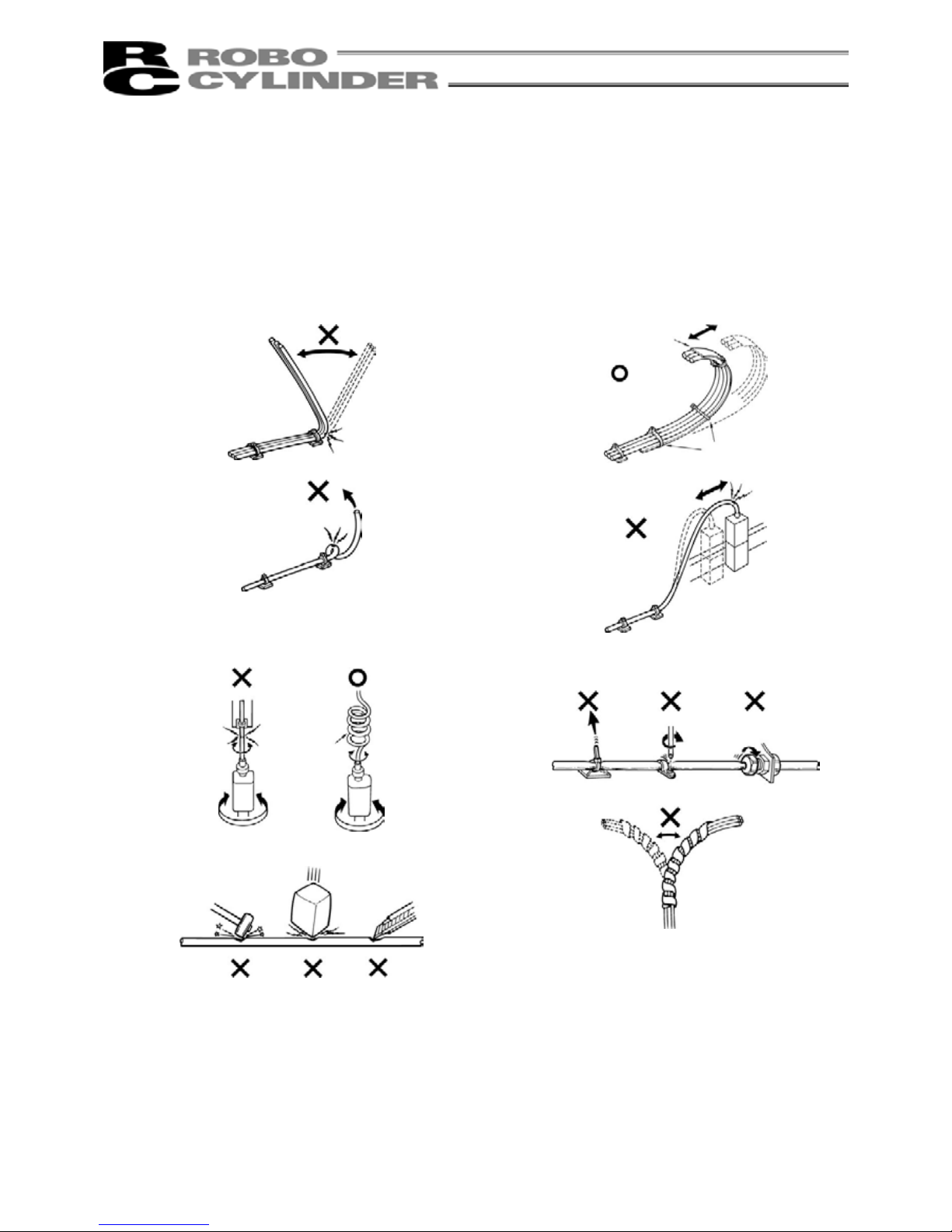
Prohibited Handling of Cables
When designing an application system using IAI’s actuators and controllers, incorrect wiring or connection of
each cable may cause unexpected problems such as a disconnected cable or poor contact, or even a runaway
system. This section explains prohibited handling of cables. Read the information carefully to connect the
cables properly.
1.
Do not let the cable flex at a single point.
2.
Do not let the cable bend, kink or twist.
3.
Do not pull the cable with a strong force.
4.
Do not let the cable receive a turning force at a
single point.
5.
6.
Do not pinch, drop a heavy object onto or cut the
cable.
When fixing the cable, provide a moderate
slack and do not tension it too tight.
Steel band
(piano wire)
Bundle loosely.
Use a curly cable.
Do not use a spiral
tube where the cable
flexes frequently.
Page 10
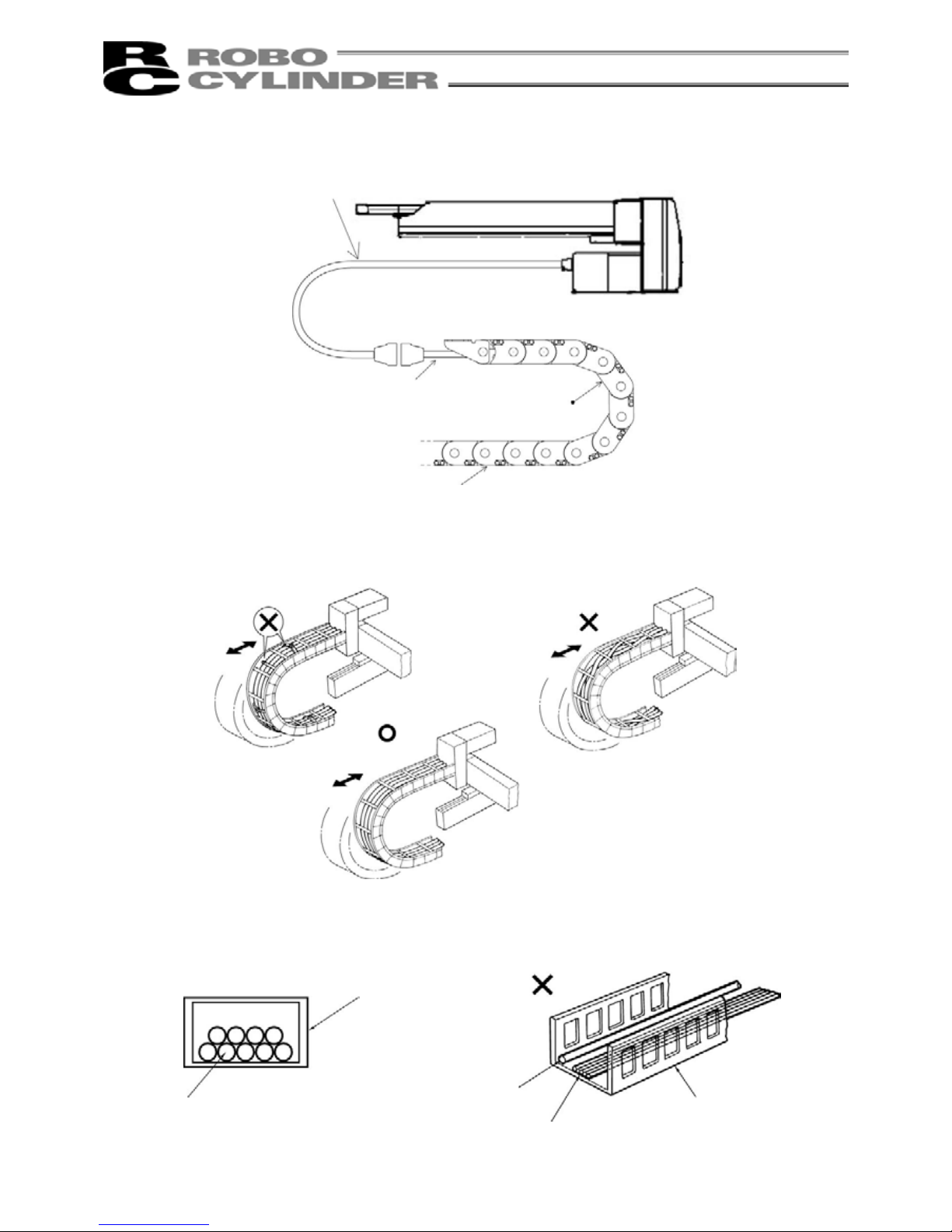
7.
Notes on using cable bearers
● The supplied cables are not robot cables.
Accordingly, never store the cables in a cable bearer.
● Always use a robot cable for
each relay cable.
● Use a cable bearer with a bending radius (r)
of 50mm or greater.
● Do not let the cable get tangled or kinked in a cable bearer or flexible tube. When bundling the cable, keep
a certain degree of flexibility (so that the cable will not become too taut when bent).
● Do not cause the cables to occupy more than
60% of the space in the cable bearer.
● Do not lay signal lines together with circuit
lines that create a strong electric field.
Bending radius (r)
Cable beare
r
Cable
Power line
Signal lines (flat cable)
Duct
Page 11

Table of Contents
1. Foreword.................................................................................................................................................... 1
2. Safety Precautions..................................................................................................................................... 1
2.1 Basic Operating Instructions............................................................................................................... 1
2.2 Maintenance and Inspection............................................................................................................... 1
3. Warranty .................................................................................................................................................... 2
3.1 Warranty Period.................................................................................................................................. 2
3.2 Scope of Warranty.............................................................................................................................. 2
4. Names of Parts .......................................................................................................................................... 3
4.1 Motor Straight Type (Standard) RCP2................................................................................................ 3
4.2 Motor Straight Type (Cleanroom Specification) RCP2CR................................................................... 4
4.3 Motor Reversing Type......................................................................................................................... 6
5. Transporting and Handling......................................................................................................................... 8
5.1 Handling the Actuator ......................................................................................................................... 8
5.1.1 Handling the Packed Unit.............................................................................................................. 8
5.1.2 Handling the Actuator after It is Unpacked.................................................................................... 8
5.2 Handling the Actuator Assembly......................................................................................................... 9
5.2.1 Condition of Shipment from IAI (Assembled)................................................................................. 9
5.2.2 Handling after Assembly with Peripheral Equipment..................................................................... 9
6. Operating and Storage Environment........................................................................................................ 10
6.1 Operating Environment..................................................................................................................... 10
6.2 Storage Environment ........................................................................................................................ 10
7. Installation................................................................................................................................................ 11
7.1 Installing the Main Body.................................................................................................................... 12
7.1.1 Using the Tapped Holes at Back of the Base (All Types)............................................................ 12
7.1.2 Using the Mounting Holes on Top of the Base (SA5C, SA6C, SA7C)......................................... 13
7.2 Mounting Surface ...........................................................................................................
................... 14
7.3 Clamp Screws
................................................................................................................................... 15
7.4 Installing the Load to the Slider
......................................................................................................... 16
8. Wiring Cable ............................................................................................................................................ 17
9. Load on the Act uator................................................................................................................................ 18
Page 12

10. Cleanroom Specification.......................................................................................................................... 20
10.1 Recommended Suction Rate............................................................................................................ 20
10.2 Suction Joint ..................................................................................................................................... 20
11. Maintenance ............................................................................................................................................ 21
11.1 Maintenance Schedule ..................................................................................................................... 21
11.2 Visual Inspection of the Machine Exterior......................................................................................... 21
11.3 Cleaning............................................................................................................................................ 21
11.4 Interior Inspection ............................................................................................................................. 22
11.5 Internal Cleaning............................................................................................................................... 23
11.6 Lubricating the Guides and Ball Screw............................................................................................. 23
11.6.1 Other than Cleanroom Specification.......................................................................................... 23
11.6.2 Cleanroom Specification............................................................................................................ 24
11.6.3 How to Apply Grease................................................................................................................. 25
11.7 Replacing/Adjusting the Stainless Sheet .......................................................................................... 26
11.8 Reduction Belt [Motor Reversing Type]:........................................................................................... 31
11.8.1 Inspecting the Belt......................................................................................................................... 31
11.8.2 Applicable Belt .............................................................................................................................. 31
11.8.3 Adjusting the Belt Tension ............................................................................................................ 31
●SA5R, SA6R ............................................................................................................................... 31
●SA7R........................................................................................................................................... 32
●SS7R, SS8R, HS8R.................................................................................................................... 32
11.8.4 Replacing the Belt......................................................................................................................... 33
●SA5R, SA6R ............................................................................................................................... 33
●SA7R........................................................................................................................................... 36
●SS7R, SS8R, HS8R.................................................................................................................... 39
11.9 Replacing the Motor.......................................................................................................................... 41
11.9.1 Motor Straight Type....................................................................................................................... 41
●SA5C, SA6C .....................................................................................................................
.......... 41
●SA5C, SA6C ............................................................................................................................... 45
●SS7C
........................................................................................................................................... 50
●SS8C, HS8C............................................................................................................................... 55
11.9.2 Motor Reversing Type................................................................................................................... 59
●SA5R, SA6R ............................................................................................................................... 59
●SA7R........................................................................................................................................... 63
●SS7R, SS8R, HS8R.................................................................................................................... 65
Appendix · How to use the home mark ........................................................................................................... 67
Page 13

1
1. Foreword
Thank you for purchasing the Robo Cylinder Actuator. This manual explains the structure, correct operation
and maintenance of the Robo Cylinder Actuator. Please read this manual carefully before using the actuator.
For more complete information on operating the actuator, please refer to the controller operating manual.
2. Safety Precautions
2.1 Basic Operating Instructions
• Please do not attempt to use or operate the actuator in any manner not indicated in this manual or the
controller manual.
• Please make sure to use only the cable provided by IAI to connect the actuator and controller.
• Please do not allow people within the moving range of the unit when it is in operation or when the power is
ON since this is dangerous.
2.2 Maintenance and Inspection
• When doing maintenance and inspection work, alw ays shut down the controller power first.
• When doing inspection, make sure that no one can inadvertently turn the power ON.
• Make sure that a sign indicating work in progress is clearly visible.
• If several persons are working, make sure to watch out for each other's safety. In particular, check before
turning power ON or OFF and let others know if you are doing work involving axis movement.
(Note)
• The content of this manual is subject to change without notice for the purpose of improvement.
• This manual was created with utmost attention to accuracy. Should you find any error, howe ver, or if you
have any question, please contact IAI’s Sales Engineering or Technical Service Section.
Page 14

2
3. Warranty
3.1 Warranty Period
Warranty period shall be either of the following periods whichever ends first:
• 18 months after shipment from our factory
• 12 months after delivery to a specified location
• 2500 hours of operation time
3.2 Scope of Warranty
If a breakdown occurs within the period specified above and is due to the manufacturer's error, we will repair
the unit at no cost. However, the following items are not covered by this warranty.
• Faded paint or other changes that occur naturally over time.
• Consumable components that wear out with use (stainless sheet, etc.).
• Unit seems to be noisy or similar impressions that do not affect machinery performance.
• Damage resulting from improper handling by the user or lack of proper maintenance.
• Any alterations made by other than IAI or its representatives.
• Breakdowns caused by using controllers made by other manufacturers.
• Any damages caused by fire and other natural disasters or accidents.
The warranty pertains to the purchased product itself and does not cover any damages that might arise from
a breakdown of the supplied product.
Any repairs will be done at our factory. Even if the product is still covered under the warranty period, we will
assess a separate charge for sending technicians to the customer's site.
Page 15
3
4. Names of Parts
The names of the actuator parts are indicated below.
The left and right sides are indicated by looking at the actuator from the motor end with the actuator set
down horizontally. Front end means the side opposite the motor end.
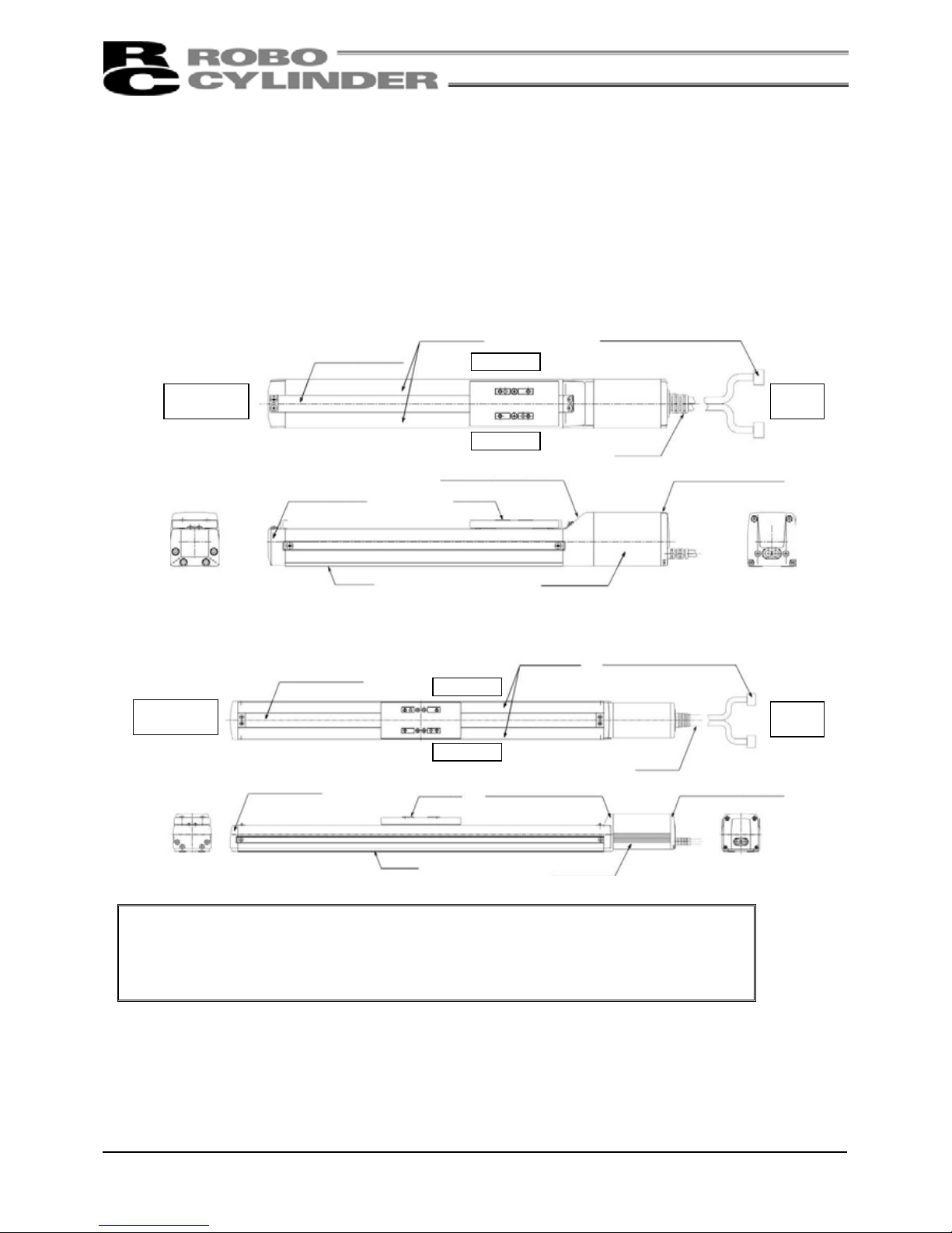
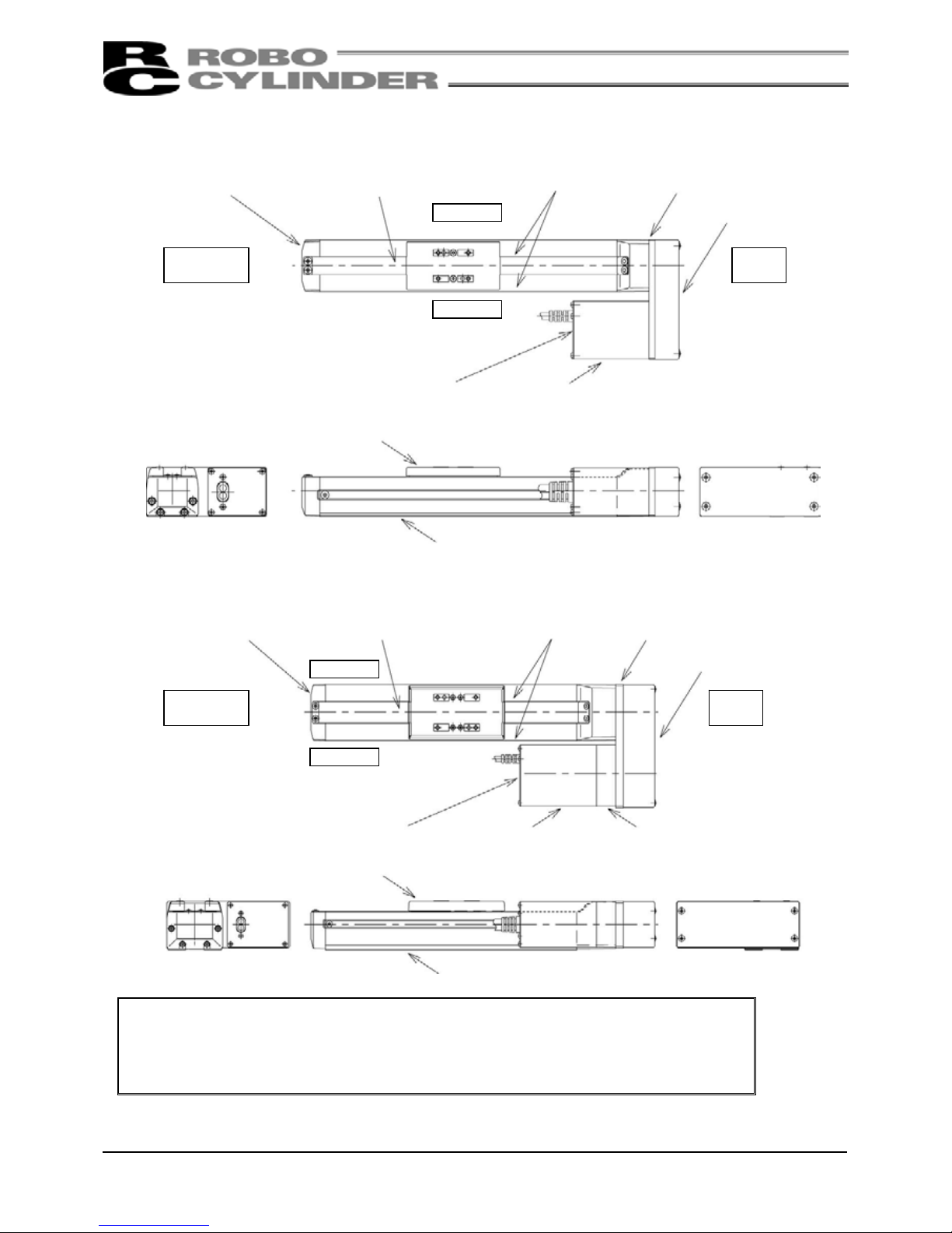
4.1 Motor Straight Type (Standard) RCP2
●SA5C, SA6C, SA7C
●SS7C, SS8C, HS8C
Caution: The cable directly connected to the actuator is not a robot cable even when
ordered with a robot cable option. When designing, please make sure not to give
repeated bending loads to this cable.
The robot cable is applicable only to the connecting cables.
Stainless Sheet
Opposite
Motor End
Side Cove
r
Right Side
Left Side
Cable Joint Connector
Cable
Motor
End
Front Cove
r
Base
Bearing Housing
Slider
Motor End Cap
Motor Cove
r
Opposite
Motor End
Motor
End
Stainless Sheet
Side Cove
r
Cable Joint Connector
Cable
Right Side
Left Side
Front Cove
r
Slide
r
Bearing Housing
Motor End Cap
Motor Cove
r
Base
Page 16
4
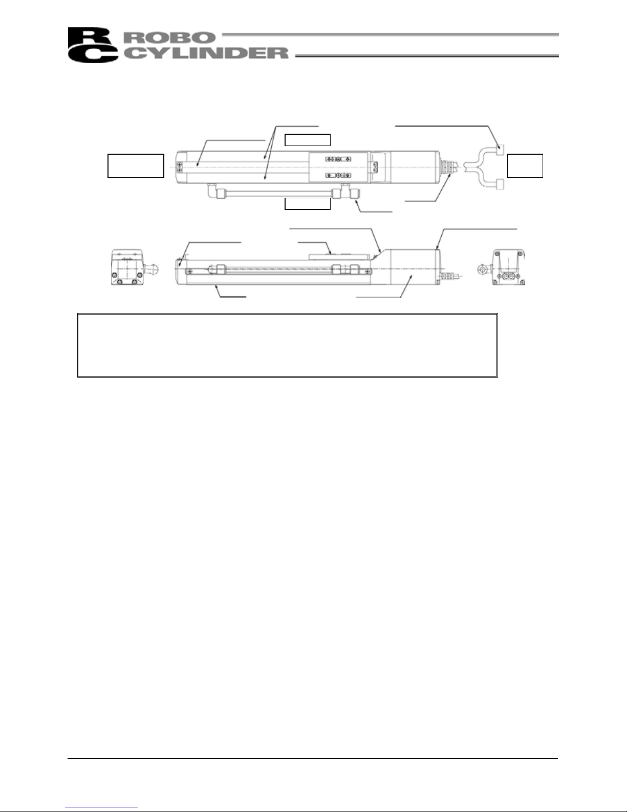
4.2 Motor Straight Type (Cleanroom Specification) RCP2CR
●SA5C, SA6C, SA7C
Caution: The cable directly connected to the actuator is not a robot cable even when
ordered with a robot cable option. When designing, please make sure not to give
repeated bending loads to this cable.
The robot cable is applicable only to the connecting cables.
Stainless Sheet
Opposite
Motor End
Side Cove
r
Right Side
Left Side
Cable Joint Connector
Cable
Motor
End
Front Cove
r
Base
Bearing Housing
Slider
Motor End Cap
Motor Cove
r
Suction
Joint
Page 17

5
●SS7C, SS8C, HS8C
Caution: The cable directly connected to the actuator is not a robot cable even when
ordered with a robot cable option. When designing, please make sure not to give
repeated bending loads to this cable.
The robot cable is applicable only to the connecting cables.
Stainless Sheet
Opposite
Motor End
Side Cove
r
Right Side
Left Side
Cable Joint Connector
Cable
Motor
End
Front Cove
r
Base
Bearing Housing
Slider
Motor End Cap
Motor Cove
r
Suction Joint
Page 18
6
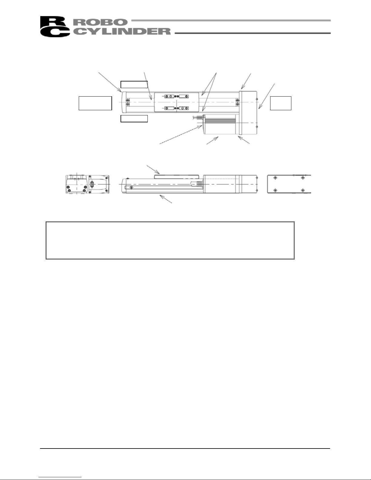
4.3 Motor Reversing Type
●SA5R, SA6R
●SA7R
Caution: The cable directly connected to the actuator is not a robot cable even when
ordered with a robot cable option. When designing, please make sure not to give
repeated bending loads to this cable.
The robot cable is applicable only to the connecting cables.
Stainless Sheet
Opposite
Motor End
Side Cove
r
Right Side
Left Side
Cable
Motor
End
Front Cove
r
Base
Mounting Flange
Pulley Cover
Motor End Cap Motor Cove
r
Slider
Stainless Sheet
Opposite
Motor End
Side Cove
r
Right Side
Left Side
Cable
Motor
End
Front Cove
r
Base
Mounting Flange
Pulley Cover
Motor End Cap
Motor Cove
r
Slider
Motor Bracket
Page 19
7
●SS7R, SS8R, HS8R
Caution: The cable directly connected to the actuator is not a robot cable even when
ordered with a robot cable option. When designing, please make sure not to give
repeated bending loads to this cable.
The robot cable is applicable only to the connecting cables.
Stainless Sheet
Opposite
Motor End
Side Cove
r
Right Side
Left Side
Mounting Flange
Motor Bracket
Motor
End
Front Cove
r
Base
Slider
Motor End Cap Motor Cove
r
Pulley Cove
r
Page 20
8
5. Transporting and Handling
5.1 Handling the Actuator
5.1.1 Handling the Packed Unit
Unless otherwise specified, each actuator (axis) is shipped individually. Please make sure that the shipping
box is not dropped or subjected to strong impact during transport.
• Operators should not carry heavy shipping boxes by themselves.
• If the shipping box is left standing, it should be in a horizontal position.
• Do not climb on top of the shipping box.
• Do not place heavy objects which may deform the shipping box or objects with concentrated loads on top of
the box.
5.1.2 Handling the Actuator after It is Unpacked
Lift the actuator up by the base to remove it from the packing.
• When carrying the actuator, make sure not to bump it. Take particular care with the front cover and motor
cover.
• Do not exert excessive force on any part of the actuator.
• Be careful not to cause the cables to receive a tensile force.
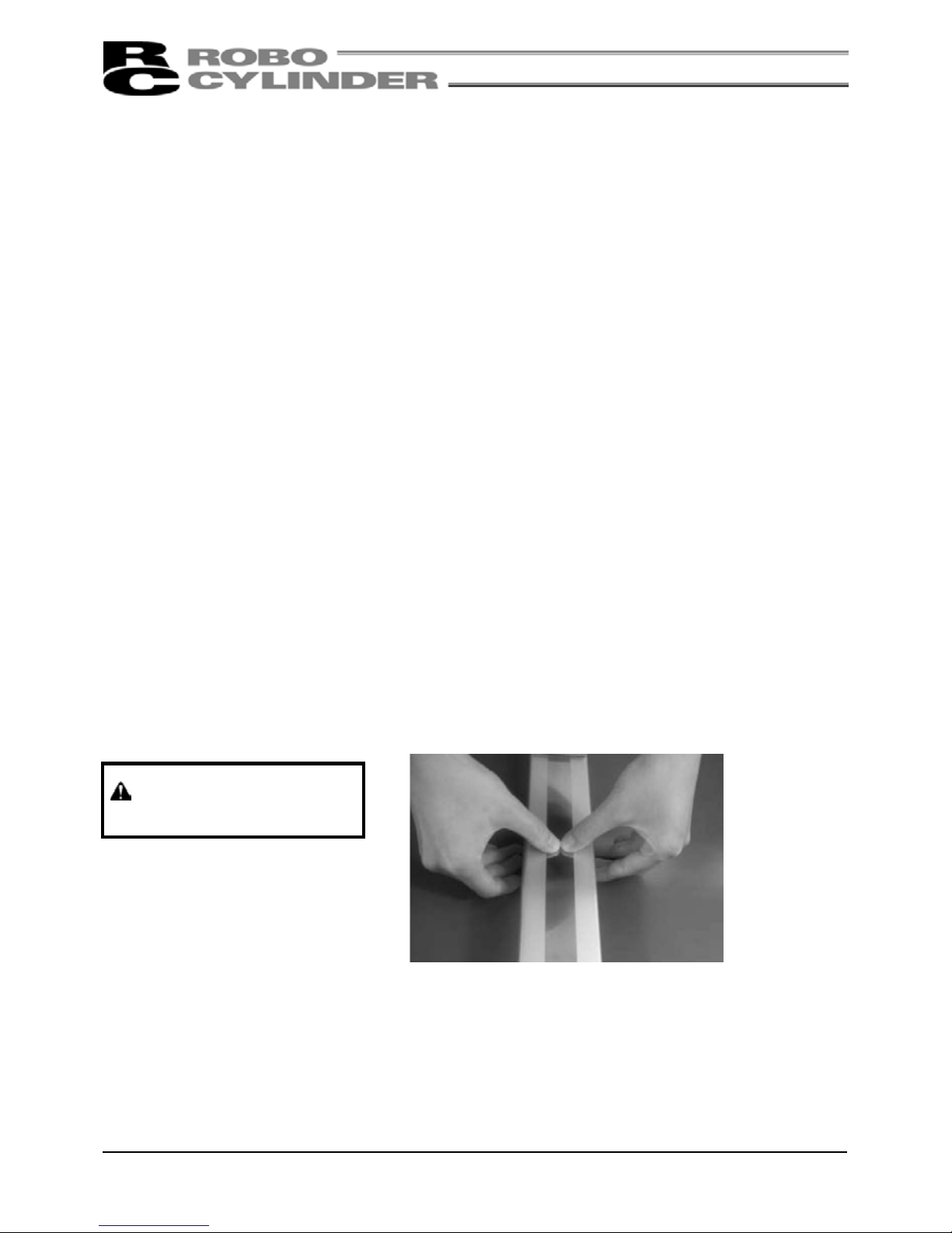
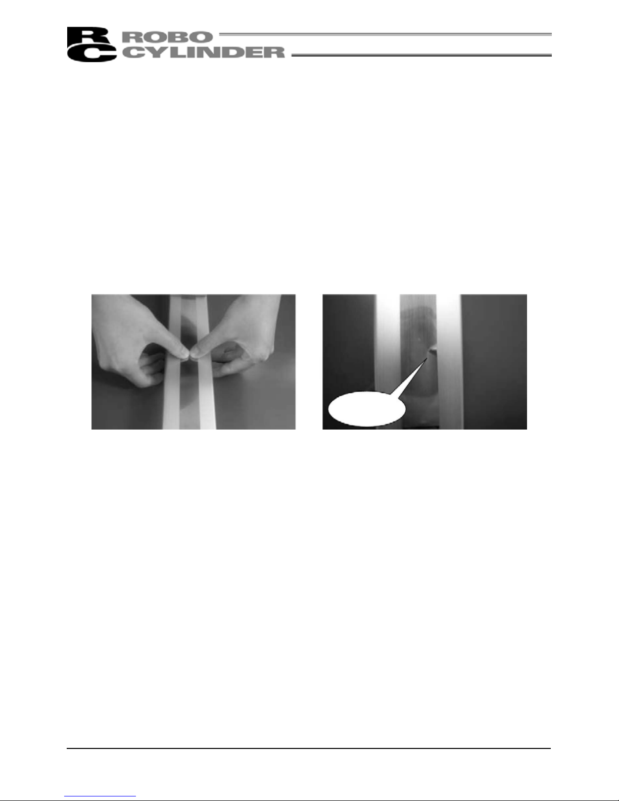
• Be careful when handling the stainless sheet
The stainless sheet is designed very thin (thickness: 0.1mm) in order to ensure flexibility. Therefore, the
stainless sheet is easily dented or scratched. Once dented or scratched, the stainless sheet may break during
use.
Warning: Do not press the sheet
directly with hands.
*Please refer to Section 4 above for the names of the actuator parts.
Page 21

9
5.2 Handling the Actuator Assembly
Make sure to the following instructions when transporting an assembly of actuator axes.
5.2.1 Condition of Shipment from IAI (Assembled)
The actuators you have ordered are assembled at IAI, after which the assembly receives a shipping inspection
and is shipped in an outer frame with skids.
The assembly is packed with sliders securely affixed so that they will not move unexpectedly during
transportation. In the case of a combined unit, the actuator ends are secured to prevent swinging due to
external vibration.
• The package is not designed with special considerations for protection against impact due to dropping or
collision, so please handle the package with care. Also, do not place any heavy object on the outer frame, as
it is not strong enough to withstand loads.
• When suspending the package using ropes, etc., pass the ropes from underneath the reinforcement frames
at the bottom of the skids. When lifting with a forklift, also place the forks underneath the skids.
• Set down the package carefully so as not to apply impact to the assembly or cause it to bounce.
After unpacking, handle the actuator assembly correctly by observing the instructions given below.
5.2.2 Handling after Assembly with Peripheral Equipment
When transporting the actuators that have been assembled with peripheral equipment either at IAI or at your
site, observe the instructions given below.
• Secure each slider to prevent unexpected movement during transportation.
• If any actuator end is protruding, secure it to prevent swinging due to external vibration.
• If the actuator ends are not secured, do not apply any impact force exceeding 0.3G during transportation.
• When suspending the actuator-assem bled peripheral equipment using ropes, etc., make sure that the ropes
do not contact the actuators directly.
• Pass the ropes over appr opriate cushion materials, and make sure the loads from the ropes will be received
directly by the base of each actuator.
• Secure the end of the Y-axis using a separate rope to maintain the axis in a stable horizontal position. At this
time, be careful not to apply loads on the screw cover.
• Be careful not to allow the brackets, covers and connector box of each actuator to receive loads. Also protect
the cables from pinching or excessive deformation.
Page 22
10
6. Operating and Storage Environment
6.1 Operating Environment
The actuator should be set up in an environment, which meets the following criteria:
• Avoid direct sunlight.
• Avoid radiant heat from strong heat sources such as a furnace.
• Ambient temperature should be 0 - 40°C.
• The humidity should be less than 85% and there should be no condensation.
• Avoid exposure to corrosive or combustible gases.
• The area should have very little dust and be suitable for normal assembly operation.
• Avoid exposure to oil mist or fluids used in cutting.
• The unit should not be subject to impact or vibrations.
• Avoid extreme electromagnetic waves, ultraviolet rays and radiation.
• This product is not intended to be used in a chemical environment.
In general, the environment should be one in which an operator can work without protective equipment or
protective clothing.
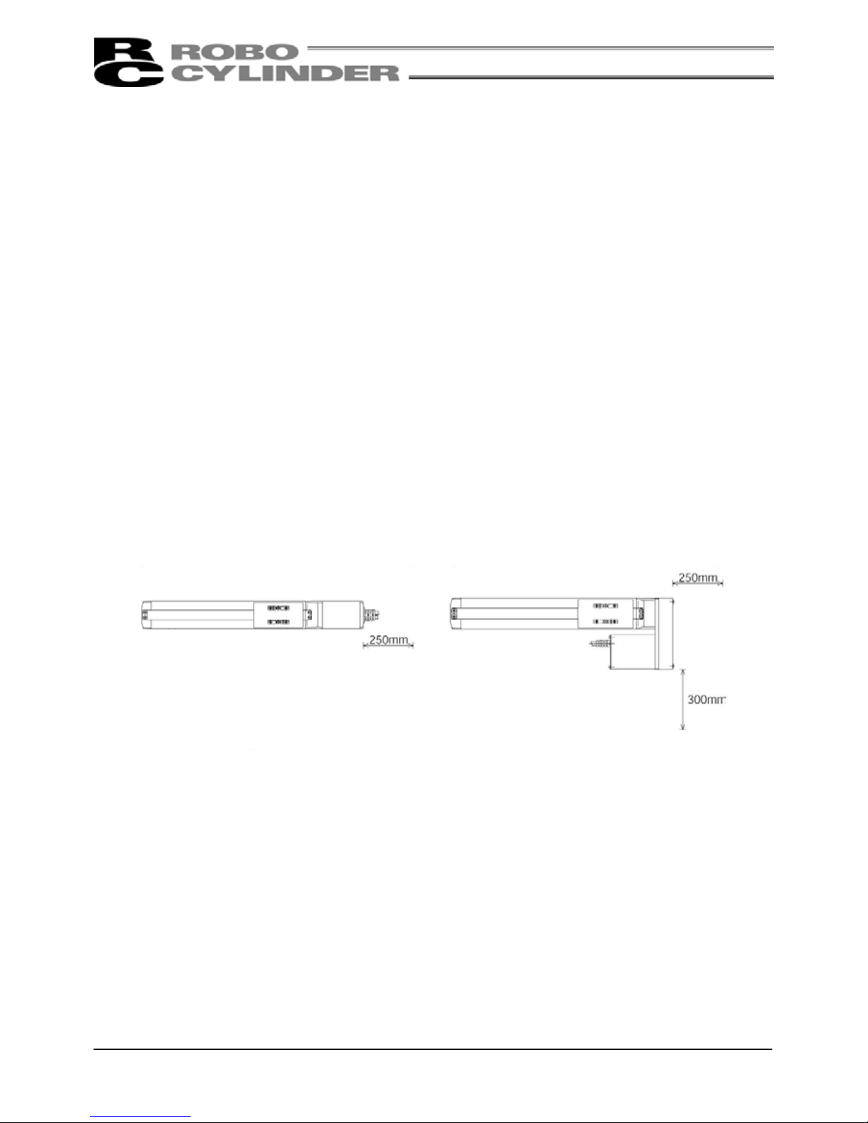
Work space needed for maintenance/inspection
6.2 Storage Environment
The storage environment should be similar to the operating environment. In addition, you must take
precautions against condensation if the unit is to be stored for a long period of time. Unless there are special
instructions, we do not include moisture absorption agents when shipping the unit. If you are storing the unit
where condensation might occur, then you must treat the entire package from outside of the package or treat
the unit itself after it is unpacked to prevent condensation. The unit can withstand up to 60°C during a short
storage interval but only up to 50°C if the storage period is longer than one month.
[
Motor Straight T
y
pe]
[
Motor Reversing Type
]
Page 23
11
7. Installation
Notes on Installation
The stainless sheet is designed very thin (thickness: 0.1mm) in order to ensure flexibility. Therefore, the
stainless sheet is easily dented or scratched. Once dented or scratched, the stainless sheet may break during
use.
When installing the stainless sheet, make sure to the following points:
1. Do not press the sheet directly with
hands.
2. Protect the sheet from dents by making
sure not to drop tools and workpieces
onto the sheet.
3. Do not allow powder dust or iron powd er to generate around the stainless sheet.
If it generates, wipe the stainless sheet fully after operation to remove all particles attached to the
sheet.
If the actuator is operated with the stainless sheet carrying foreign particles, those particles may
enter the slider and damage the sheet or cause the sheet to deform, lift or present other problems.
For SS and HS, the stainless sheet is held in place by means of a magnet on the side covers. Since
metal particles, iron powder or other magnetic substances in ambient air are likely to attach to the
magnets, make sure to the surrounding environment.
Dent
Page 24

12
7.1 Installing the Main Body
Mount the actuator to a machined surface or one of the flat surfaces of comparable precision.
The side faces and lower surface of the base run parallel with the guides. When traveling precision is required,
use these as the reference planes for mounting.
7.1.1 Using the Tapped Holes at Back of the Base (All Types)
Tapped holes are provided on the back of the base for
mounting the actuator. Install the actuator using these
tapped holes. The effective depths of base mounting screws
are listed below. Be careful not to let the ends of bolts
project from the holes. If necessary, use the additional
reamed holes that are provided for positioning purposes.
Type Tap Size Screw Effective Depth Reamed Hole
SA5C M4 4mm or more and 7mm or less φ4H7, depth 5mm or less
SA6C M5 5mm or more and 9mm or less φ4H7, depth 5mm or less
SA7C M5 5mm or more and 9mm or less φ4H7, depth 5mm or less
SS7C M5 5mm or more and 8mm or less φ4H7, depth 5mm or less
SS8C M8 8mm or more and 10mm or less Φ5H7, depth 5mm or less
HS8C M8 8mm or more and 10mm or less Φ5H7, depth 5mm or less
Page 25

13
7.1.2 Using the Mounting Holes on Top of the Base (SA5C, SA6C, SA7C)
Through holes are provided in the base for installing the
actuator on its top face.
When installing the actuator, remove the side covers.
(Remove the two thin-head screws [M3 x 6mm] for mounting
the cover using an Allen wrench of 1. 5mm across flats.)
When securing with bolts, protect the stainless sheet from
dents or damage by making sure not to drop bolts or tools
onto the stainless sheet or contact them with it.
As for mounting bolts, use hexagon socket-head bolts conforming to the applicable specification in the table
below in accordance with the machine frame material.
Type
When the mating material
is steel
When the mating material
is aluminum
Mounting Hole (Reference)
SA5C M4 × 10 M4 × 15 φ4.5 drill, φ8 counterbore depth 4.5
SA6C M4 × 10 M4 × 15 φ4.5 drill, φ8 counterbore depth 4.5
SA7C M5 × 10 M4 × 15 φ6 drill, φ9.5 counterbore depth 5.5
(Note) When reinstalling the side covers, do not let them contact the end faces of the stainless sheet. This
may damage or bend the stainless sheet, causing the sheet to deteriorate or wear quickly.
Therefore, install the side covers and check for bending according to the procedure below.
(1) To prevent the side covers from contacting
the end faces of the sheet, insert a shim
(approx. 0.1 to 0.2mm) between the sheet
and each cover to provide a slight allowance,
and gently push in the cover.
(2) Remove the slider covers and check to see
that the right and left clearances between the
slider and sheet are nearly equal and no
bending is created.
(3) Finally, move the slider back and forth several times along the entire stroke to check that the slider does not
contact the sheet.
Slider
Shee
t
Right and left clearances
are nearly equal
Page 26
14
7.2 Mounting Surface
• The mounting table should have sufficient rigidity to avoid generating vibration.
• The surface where the actuator will be mounted should be machined or be equally level and the flatness
tolerance between the actuator and the table should be within 0.05mm.
• Provide sufficient space around the actuator to permit maintenance work to be performed.
• The side and bottom faces of the actuator base provide the reference planes for slider travel.
• When traveling precision is required, use these surfaces as the reference planes for mounting.
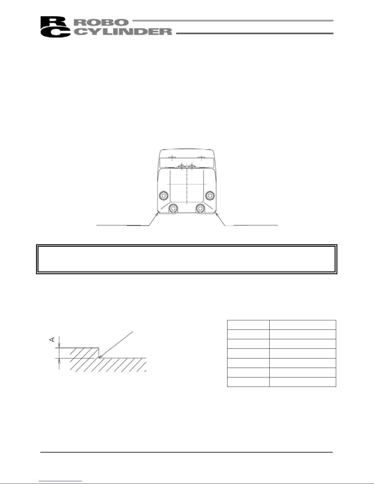
Caution: As shown above, the side faces of the base provide the reference planes for slider travel. When
precision is required, use these surfaces as the reference planes for mounting.
When using the base as the reference planes for mounting the actuator to the machine frame, follow the
machining dimensions shown below.
Type Dimension A (mm)
SA5C 2 to 3.5
SA6C 2 to 3.5
SA7C 2 to 5
SA7C 2 to 5
SS8C 2 to 5
HS8C 2 to 5
Reference plane
(
Side face of the base
)
R0.3 or less
Reference plane
(
Side face of the base
)
Page 27

15
7.3 Clamp Screws
• The male screws for mounting the base should be M4 for SA5C, M5 for SS7C/SA6C/SA7C, and M8 for
SS8C/HS8C. (Use hexagon socket-head bolts.)
• For the bolts, we recommend high strength bolts of ISO-10.9 or higher.
• When using a foot base to attach to a mounting table, use the special washer made for high strength bolts
that comes with the actuator if the bolt is M8 or larger. This is unnecessary for M6 or smaller bolts. Do not use
a common spring washer.
• The recommended screw torque is given below.
Screw Torque
Screw Nominal
Diameter
When the bolt seating surface is steel When the bolt seating surface is aluminum
M4 3.6N·m (0.38kgf·m) 1.8N·m (0.18kgf·m)
M5 7.3N·m (0.74kgf·m) 3.4N·m (0.35kgf·m)
M6 30.0N·m (3.1kgf·m) 11.5N·m (1.17kgf·m)
Page 28
16
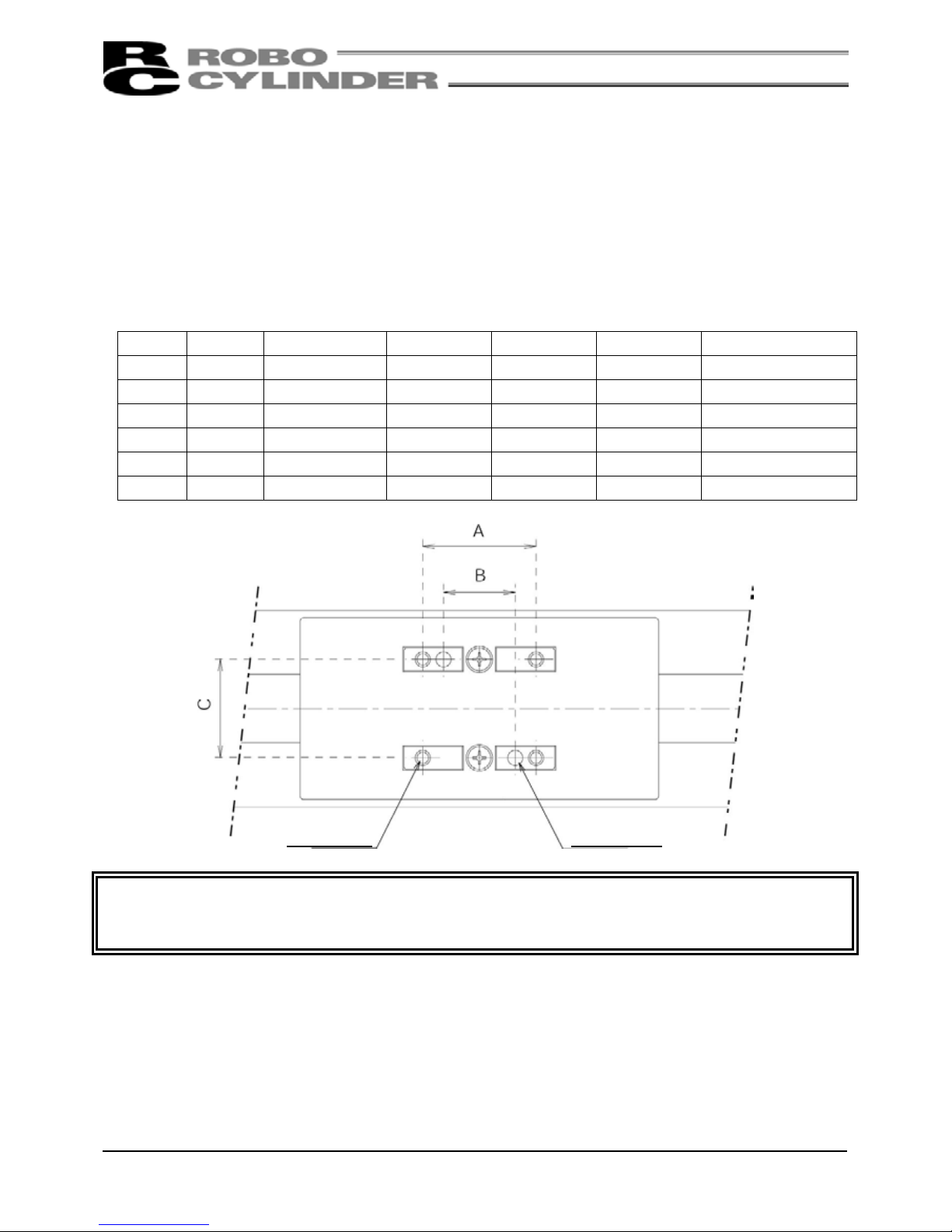
7.4 Installing the Load to the Slider
• Tapped holes are provided on the slider for installing the load. The method of clamping varies according to
how to mount the main body.
• In case of moving the main body with the slider secured, use the same tapped holes on the slider.
• Please use two reamed holes on the slider when repeatability of mounting and dismounting is required. When
fine adjustment of the squareness is necessary, use only one reamed hole to allow adjustment.
Sizes and depths of tapped holes and reamed holes on slider
Model Tap size Depth of thread A B C Reamed hole size
SA5C M4 9mm 30mm 19mm 26mm φ4H7, depth 6mm
SA6C M5 9mm 50mm 32mm 31mm φ5H7, depth 6mm
SA7C M5 10mm 50mm 32mm 39mm φ5H7, depth 10mm
SS7C M5 10mm 50mm 32mm 32mm φ5H7, depth 10mm
SS8C M8 10mm 75mm 45mm 45mm φ8H7, depth 10mm
HS8C M8 10mm 75mm 45mm 45mm φ8H7, depth 10mm
*Caution: When installing the load, do not allow adhesives, paints or other viscous substances to attach to the
stainless sheet. Also, avoid applying a concentrated force that will dent the sheet. It may cause the
slider to malfunction or damage the sheet.
Tapped hole
Reamed hole
Page 29

17
8. Wiring Cable
• In an application where the cable cannot be anchored, try to place the cable so that it sags only under its own
weight or use a self-standing type cable as a large radial wire duct to limit the load on the cable.
• Never cut and/or reconnect the cables supplied with the product for the purpose of extending or shortening
the cable length.
• The cables supplied with an actuator offer excellent flexibility, but they are not robot cables. If the cables are
to be stored in a movable cable duct (cable bearer, etc.), use robot cables.
For cable modification, please contact your IAI sales representatives.
Page 30

18
9. Load on the Actuator
Do not exceed the load shown in the load specification column. Please note the slider moment, allowable
overhang length and the load weight.
Allowable load moments
Type Ma Mb Mc
SA5C 4.9N·m (0.5kgf·m) 6.8N·m (0.7kgf·m)
Stroke: 50 to 300mm - 11.7N·m (1.2kgf·m)
Stroke: 350 to 500mm - 7.8N·m (0.8kgf·m)
SA6C 8.9N·m (0.9kgf·m) 12.7N·m (1.3kgf·m) 18.6N·m (1.9kgf·m)
SA7C 13.9N·m (1.4kgf·m) 19.9N·m (2.0kgf·m) 38.3N·m (3.9kgf·m)
SS7C 14.7N·m (1.5kgf·m) 14.7N·m (1.5kgf·m) 33.3N·m (3.4kgf·m)
SS8C 36.3N·m (3.7kgf·m) 36.3N·m (3.7kgf·m) 77.4N·m (7.9kgf·m)
HS8C 36.3N·m (3.7kgf·m) 36.3N·m (3.7kgf·m) 77.4N·m (7.9kgf·m)
Allowable overhang lengths
Model Ma direction Mb direction Mc direction
SA5C 150mm or less 150mm or less 150mm or less
SA6C 220mm or less 220mm or less 220mm or less
SA7C 230mm or less 230mm or less 230mm or less
SS7C 300mm or less 300mm or less 300mm or less
SS8C 450mm or less 450mm or less 450mm or less
HS8C 450mm or less 450mm or less 450mm or less
• The allowable overhang lengths are based on a configuration where the center of gravity of the load mounted
on the actuator corresponds to the center of the overhang length.
Mb, Mc
directions
Ma
direction
Directions of moment forces
Directions of allowable overhangs
Page 31

19
The body of the base warps easily when the actuator is used as the Y-axis in an X-Y overhang setup. In this
case, use the actuator so that the Ma and Mc moments are kept to one-half the allowable moment or less (see
the figure below).
Caution: Allowing the slider to receive an excessive load moment will shorten the service life of the guides. If
the allowable overhang length is exceeded, vibration may generate or the service life of the guides
may be reduced.
Y-axis
X-axis
The Ma and Mc moments applied
on this slider should be kept to
one-half the allowable moment.
Page 32

20
10. Cleanroom Specification
This actuator can deliver performance which ensures its operation in conformance with the requirements of
cleanliness class 10 (0.1μm) by suctioning air into the suction joint. The recommended suction rate of each
model at the maximum speed is specified below.
10.1 Recommended Suction Rate
Model Maximum speed Suction rate (NI/min)
SA5C, lead 12mm 600mm/s 50
SA5C, lead 6mm 300mm/s 30
SA5C, lead 3mm 150mm/s 15
SA6C, lead 12mm 600mm/s 50
SA6C, lead 6mm 300mm/s 30
SA6C, lead 3mm 150mm/s 15
SA7C, lead 16mm 533mm/s 70
SA7C, lead 8mm 266mm/s 40
SA7C, lead 4mm 133mm/s 30
SS7C, lead 12mm 600mm/s 50
SS7C, lead 6mm 300mm/s 30
SS7C, lead 3mm 150mm/s 15
SS8C, lead 20mm 666mm/s 80
SS8C, lead 10mm 333mm/s 40
SS8C, lead 5mm 165mm/s 20
HS8C 1200mm/s 180
• If there is suction equipment, check its capacity. If there is no suction equipment, select suction equipment
such as a vacuum pump and blower by referring to the values above.
10.2 Suction Joint
• As for the suction joint, a one-touch type is employed and its structure allows the joint to be easily connected
with a commercial air tube.
Model Joint type Tube outer diameter
SA5C
SA6C
SA7C
SS7C
KAT08-U01 (SMC) φ8
SS8C
HS8C
KAT12-U03 (SMC) φ12
A
ir tube connecting port
Page 33

21
11. Maintenance
11.1 Maintenance Schedule
Perform maintenance work according to the schedule below.
The schedule is set assuming eight hours of operation a day. When the operation time is long such as a
24-hour operation, shorten the maintenance intervals as needed.
Visual inspection Check interior Grease supply
Start of operation ○
After 1 month of operation ○
After 6 months of operation ○ ○
After 1 year of operation ○ ○ ○
Every 6 months thereafter ○
Every 1 year ○ ○ ○
11.2 Visual Inspection of the Machine Exterior
Check the following items when carrying out visual inspection.
Body Loose mounting bolts?
Cables Damage to cables or connection to connector box?
Stainless sheet Damage or foreign deposit?
General Unusual noise or vibrations?
11.3 Cleaning
• Clean the exterior as needed.
• Wipe off dirt with a soft cloth.
• Do not use strong compressed air on the actuator as this may force dust into the crevices.
• Do not use petroleum-based solvents on plastic parts or painted surfaces since such solvents damage them.
• If the unit is badly soiled, apply a neutral detergent or alcohol to a soft cloth, and wipe gently.
Page 34

22
11.4 Interior Inspection
Turn off the power, remove the side covers, and then visually inspect the interior.
Check the following items during interior inspection.
Body Loose mounting bolts?
Guides Lubrication appropriate? Soiling?
Ball screw Lubrication appropriate? Soiling?
How to inspect the interior:
1) Remove both side covers.
Use an Allen wrench of 1.5mm across flats for SA5C/SA6C/SA7C/SS7C or an Allen wrench of 2.00mm
across flats for SS8C/HS8C.
Make a visual check of the interior to see if there is any dust
or foreign matter in the unit and check the lubrication. Even
if the grease you see around the parts is brown, the
lubrication is fine as long as the traveling surface appears
shiny.
2) If the grease becomes dirty and dull or if the grease has worn away due to extended operating time,
lubricate the parts after cleaning them.
3) When the inspection/maintenance work is complete, install the side covers.
Tightening torque: SA5C/SA6C/SA7C/SS7C: Thin-head screw M3 × 6 - 87.2N·cm (8.90kgf·cm)
SS8C/HS8C: Thin-head screw M4 × 6 - 204N·cm (20.8kgf·cm)
When installing the side covers, do not let them contact the
end faces of the stainless sheet. This may damage or bend
the stainless sheet, causing the sheet to deteriorate or wear
quickly. To prevent this problem, insert a shim (approx. 0.1
to 0.2mm) between the sheet and each cover between the
sheet and each cover to provide a slight allowance, and
gently push in the cover.
Caution: When checking the interior, be careful not to bend or scratch the stainless sheet. Wear protective
gloves when handling the stainless sheet, because it has sharp edges that may cause accidental
cuts.
The front cover is supporting the ball screw; so do not disassemble the front cover.
If the front cover is misaligned, the shaft centers may become offset, thus increasing the traveling
resistance, reducing the service life of each part, or generating noise.
Page 35

23
11.5 Internal Cleaning
• Wipe off dirt with a soft cloth.
• Do not use strong compressed air on the actuator as this may force dust into the crevices.
• Do not use petroleum-based solvent, neutral detergent or alcohol.
Caution: Do not use flushing oil, molybdenum grease or anti-rust lubricant.
When grease is soiled with a large amount of foreign substances, wipe off the dirty grease and then
apply new grease.
11.6 Lubricating the Guides and Ball Screw
11.6.1 Other than Cleanroom Specification
(1) What Grease to Use on the Guides
The following grease is used when we ship the unit.
Idemitsu Kosan Daphne Eponex Grease No. 2
Other companies also sell a grease similar to this. If ordering from another maker, give the name of this
product and request something comparable. Comparable products include the following:
Showa Shell Oil Albania Grease No. 2
Mobil Oil Mobilux 2
(2) What Grease to Use on the Ball Screw
The following grease is used when we ship the unit.
This grease offers excellent properties such as low heat generation, and is suitable for lubricating ball screws.
Kyodo Yushi Multemp LRL3
Warning: Never use any fluorine-based grease. It will cause a chemical reaction when mixed with a
lithium-based grease and may cause damage to the actuator.
Page 36

24
11.6.2 Cleanroom Specification
(1) What Grease to Use on the Guide and Ball Screw
For guides and ball screw, a urea-based grease of low-dust-raising type which has stable torque
characteristics and superior lubrication performance as well as the anti-rust effect equivalent to that of a
lithium-based grease is used. The following grease is used when we ship the unit:
Kuroda Precision Industries C Grease
Caution: Never use grease for the standard specification. It may allow dust to generate.
Warning: Never use any fluorine-based or lithium-based grease. It will cause the grease to lose its
lubrication performance and may damage the actuator or reduce cleanliness performance
when mixed with an urea-based grease.
Page 37

25
11.6.3 How to Apply Grease
1) When greasing the guide, use a spatula or grease applicator to squeeze or inject grease into the space
between the slider and base, and then move the slider back and forth several times to let grease spread
evenly.
Apply grease on the guides on both sides.
Remove excess grease.
2) When greasing the ball screw, clean the ball screw, apply grease using a finger, and then move the slider
back and forth several times to let the grease spread evenly.
At this time, be careful not to deform the stainless sheet by accidentally touching the sheet.
Remove excess grease.
3) Install the side covers.
Tightening torque: SA5C/SA6C/SA7C/SS7C: Thin-head screw M3 × 6 87.2N·cm (8.90kgf·cm)
SS8C/HS8C: Thin-head screw M4 × 6 204N.cm (20.8kgf.cm)
Refer to 3) in 11.4, “Interior Inspection,” for notes on installing the side covers.
Page 38

26
11.7 Replacing/Adjusting the Stainless Sheet
[Items Required for Replacement]
• Replacement stainless sheet
• Clearance-checking tool (a regular slider cover with holes)
(This tool is available from IAI’s Sales Engineering Section. If you are replacing the stainless sheet, please
contact us to make a rental arrangement or purchase the tool.)
• Allen wrench set • Phillips screwdriver • Scale
[Note on Stainless Sheet Tension]
Deterioration and wear of the stainless sheet is affected by its tension.
If the stainless sheet is too tight, excessive clearances will be created between the sheet and slider covers and
the sheet may undergo a fatigue failure.
If the stainless sheet is too loose, the sheet will contact the back of the slider covers and generate shaving.
Therefore, use a dedicated adjustment tool to properly adjust the tension of the stainless sheet so that the
clearances between the stainless sheet and slider covers conform to the specified dimension.
[Names of Each Part]
Stainless-sheet
retainer plate
Slider-cover affixing screw
(flat countersunk-head
screw)
Stainless-sheet
retainer screw
Stainless sheet Slider cover
Stainless-sheet
retainer screw
Page 39

27
[Procedure]
1) Remove the slider-cover affixing screws and remove the covers.
After the slider covers have been removed
Caution: Remove the slider covers slowly and gently. If the actuator is installed on the ceiling or oriented
vertically or horizontally on its side, place a plastic bag, etc., underneath the slider covers so as not
to lose the coil springs and spacers in case they drop off.
[1] Standard specification (slider structure)
•
SA5C/SA6C
•
SA7C/SS7C/SS8C/HS8C
[2] Cleanroom specification (roller structure)
•
SA5C/SA6C
•
SA7C/SS7C/SS8C/HS8C
Sheet slider
Sheet slider
Sheet slider
Sheet slider
Plate spring
Coil spring
Coil spring
Coil spring
Coil spring
Coil spring
Coil spring
Coil spring
Coil spring
Coil spring
Coil spring
Coil spring
Coil spring
Spacer
Spacer
Roller
Roller
Roller
Roller
Page 40

28
2) Remove the stainless-sheet retainer screws on both sides and pull out the stainless sheet.
3) Guide a new stainless sheet into the slider.
4) Hold the stainless sheet in place, and affix the retainer plates and screws.
At this time, securely tighten the screws only on the motor side, and leave the screws on the counter-motor
side loose.
●How to prevent the stainless sheet from lifting (SA5C/SA6C/SA7C)
Slightly bend the stainless sheet downward near the center of the mounting holes so that the sheet can be
held securely.
5) Install the clearance-checking tool.
Sheet slider
Stainless-sheet retainer plates and screws
Securely tighten the screws only on the motor side,
and leave the screws on the counter-motor side
loose.
Stainless sheet
Near the center of the mounting holes
Slightly bend the sheet
downward.
Peripheral
openings
Center
openings
Install the clearance-checking
tool instead of the slider covers.
Page 41

29
6) Adjust the tension of the stainless sheet.
[1] While looking through the center ope ning in the clearance-checking tool, move the stainless sheet on the
loose end in the directions of arrows until the clearance between the top face of the stainless sheet and the
back of the clearance-checking tool falls within the specified range.
[2] When the stainless sheet has been properly positioned, tighten the screws on the loose end to a level that
the stainless sheet no longer moves.
Move the stainless sheet in the directions of arrows to
adjust the tension.
While looking through the center opening, check the clearance between the top face
of the stainless sheet and the back of the clearance-checking tool. (If the clearance is
within the specified tolerance range, the tension is appropriate even when the
clearance varies along the entire stroke or between right and left.)
(Standard)
(Cleanroom specification)
Page 42

30
[3] Move the slider and check the tension of the stainless sheet along the entire stroke.
If the conditions in Checkpoints 1 and 2 are not satisfied, loosen the screws and readjust the position
and tension of the stainless sheet again from [1].
Note) If the condition in Checkpoint 2 cannot be met after the readjustment, try installing the stainless sheet
in the reverse direction or placing it upside down. If the stainless sheet is still not adjusted properly,
replace it with a new sheet.
[4] When proper clearances are obtained between the slider body and stainless sheet and an absence of
contact between the two is confirmed, tighten the two screws on the loose end alternately, and then finally
tighten all screws to a uniform torque to securely affix the stainless sheet. If the screws are not tightened
uniformly, the sheet may meander or lift.
[5] Remove the clearance-checking tool and install the slider covers.
Note) Again, make sure not to lose the coil springs and spacers.
Checkpoint 1:
Check if the clearance between the top face of the stainless sheet and the back of the
clearance-checking tool falls within the specified range along the entire stroke.
Checkpoint 2:
Look through the peripheral openings and confirm that the stainless
sheet edges do not contact the slider body.
Move the slider back and forth at least three times over the entire stroke
to ensure the edges do not contact the slider.
The sheet may move during the slider strokes, but slight movement is
acceptable as long as the offset does not increase and the sheet does
not contact the slider.
If the stainless sheet contacts the slider, repeat the adjustment from [1].
The stainless sheet is not perfectly straight, but it bends to the right and
left slightly.
It is impossible to adjust the right and left clearances perfectly uniform.
Slight variation in clearance in the stroke direction or between the right
and left is acceptable, as long as the stainless sheet edges do not
contact the slider body over the entire stroke.
Clearances between stainless sheet edges and
slider body
Slider body
Stainless sheet
Apply additional torque to the screws on both ends until the stainless sheet no longer moves.
Tightening torque: SA5C/SA6C/SA7C/SS7C: 87.2N·cm (8.90kgf·cm) (Standard)
45.5N·cm (4.64kgf·cm) (Cleanroom specification) [Reference value]
SS8C/HS8C: 204N·cm (20.8kgf·cm) (Standard)
106N·cm (10.8kgf·cm) (Cleanroom specification) [Reference value]
Page 43

31
11.8 Reduction Belt [Motor Reversing Type]:
11.8.1 Inspecting the Belt
Remove the pulley cover and visually inspect the belt.
Durability of the reduction belt is affected significantly by the operating condition, and there is no standard
guideline as to when the belt should be replaced.
Generally, the belt is designed to withstand several millions of flexing loads.
As a practical guideline, replace the reduction belt when any of the conditions listed below are observed:
• The teeth and end faces of the belt have worn significantly.
• The belt has swollen due to deposits of oil, etc.
• Cracks and other damages are found on the teeth or back of the belt.
• The belt has broken.
11.8.2 Applicable Belt
Manufacturer: Bando Chemical Industries
Model: 60S2M184R: 6mm wide, Rubber STS cleanroom type specification (SA5R/SA6R)
150S3M255U: 15mm wide, Polyurethane rubber specification (SA7R)
100S3M219U: 10mm wide, Polyurethane rubber specification (SS7R)
150S3M252U: 15mm wide, Polyurethane rubber specification (SS8R/HS8R)
11.8.3 Adjusting the Belt Tension
Remove the pulley cover and loosen the four tension adjusting bolts. Apply a tensile load to the belt by moving
the motor to the left and tighten the tension adjusting bolts.
●SA5R, SA6R
SA5R, SA6R, SA7R,
SS7R, SS8R, HS8R
Move the motor cover.
Motor
Tensile load:
Tension adjusting bolts (4 pcs.)
Tension adjusting bolt tightening torque:
Use an Allen wrench of 2.5mm
across flats.
Motor-cover affixing bolts (2 pcs.)
Page 44
32
●SA7R
●SS7R, SS8R, HS8R
Motor bracket
Tensile load:
Tension adjusting bolts (4 pcs.)
Tension adjusting bolt tightening torque:
Use an Allen wrench of 3mm
across flats.
Motor bracket
Tensile load:
Tension adjusting bolts (4 pcs.)
Tension adjusting bolt tightening torque:
Use an Allen wrench of 3mm
across flats.
Page 45

33
11.8.4 Replacing the Belt
●SA5R, SA6R
[Items Required for Replacement]
• Replacement reduction belt • Allen wrench set
• Tension gauge (Capable of tensioning to 3kgf or greater)
• Strong string, looped (or long tie-band)
[Procedure]
1) Remove the pulley cover.
Remove the four affixing thin-head screws using an Allen wrench of 1.5mm across flats.
: SA5R, SA6R, SA7R, SS7R, SS8R, HS8R
2) Pull out the two motor-cover affixing bolts and move the motor cover approx. 20mm.
(Use an Allen wrench of 2.5mm across flats.)
3) Loosen the four tension adjusting bolts to loosen the belt.
(Use an Allen wrench of 2.5mm across flats.)
4) Remove the belt from the pulleys.
Page 46

34
8) Attach the pulley cap.
Tighten the hexagon socket-head bolts (M3 x 8mm, 2 pcs.) using an Allen wrench of 2.5mm across flats.
Tightening torque: 83N·cm (8.47kgf·cm)
5) Remove the pulley assembly.
•
Remove the four affixing bolts using an Allen
wrench of 2.5mm across flats.
•
Pull out the assembl
y
by hand.
6) Remove the pulley cap.
•
Remove the two affixing bolts using an Allen
wrench of 2.5mm across flats.
7) Pull out the belt and insert a new belt.
Pulley cap
Insert the belt into
this clearance.
Page 47

35
Tightening torque: 83N·cm (8.47kgf·cm) Tightening torque: 87.2N·cm (8.90kgf·cm)
9) Install the pulley assembly.
•
Align the angles of projections and depressions
on the couplings.
• Tighten the hexagon socket-head
screws (M3 × 22, 4 pcs.) using an Allen
wrench of 2.5mm across flats.
Align the angles of projections and depressions.
10) Loop the belt over the pulleys.
11) Pass a looped strong string (or long tie-band) aro und the motor-end flange and pull it with a tension
gauge to the specified tension. In this condition, uniformly tighten the adjusting bolts (hexagon
socket-head bolts: M3 × 10, 4 pcs.).
(Use an Allen wrench of 2.5mm across flats.)
Tightening torque: 83N·cm (8.47kgf·cm)
Tension: 2.5kgf
Adjusting bolt tightening torque:
162N·cm (16.5kgf·cm)
12) Install the motor cover.
Tighten the hexagon socket-head screws
(M3 × 12, 2 pcs.) using an Allen wrench o
f
2.5mm across flats.
13) Install the pulley cover.
Tighten the thin-head screws (M3 × 6, 4
pcs.) using an Allen wrench of 1.5mm
across flats.
Page 48

36
●SA7R
[Items Required for Replacement]
• Replacement reduction belt • Allen wrench set
• Tension gauge (Capable of tensioning to 8kgf or greater)
• Strong string, looped (or long tie-band)
[Procedure]
1) Remove the pulley cover.
Remove the four affixing thin-head screws using an Allen wrench of 1.5mm across flats.
2) Loosen the four tension adjusting bolts to
loosen the belt.
(Use an Allen wrench of 3mm across flats.)
4) Remove the pulley assembly.
•
Remove the four affixing bolts using an
Allen wrench of 2.5mm across flats.
•
Pull out the assembly by hand.
3) Remove the belt from the pulleys.
Page 49

37
7) Install the pulley cap.
Tighten the hexagon socket-head bolts (M3 × 10, 4 pcs.) using an Allen wrench of 2.5mm across flats.
Tightening torque: 83N·cm (8.47kgf·cm)
5) Remove the pulley assembly.
• Remove the four affixing bolts using an Allen
wrench of 2.5mm across flats.
6) Pull out the belt and insert a new belt.
Pulley cap
Insert the belt into
this clearance.
Page 50

38
8) Install the pulley assembly.
•
Align the angles of projections and depressions
on the couplings.
• Tighten the hexagon socket-head
screws (M3 × 40, 4 pcs.) using an Allen
wrench of 2.5mm across flats.
Align the angles of projections and depressions.
9) Loop the belt over the pulleys.
10) Pass a looped strong string (or long tie-band) aro und the motor bracket and pull it with a tension gauge
to the specified tension. In this condition, uniformly tighten the adjusting bolts (hexagon socket-head
bolts: M4 × 20, 4 pcs.).
(Use an Allen wrench of 3mm across flats.)
Tightening torque: 83N·cm (8.47kgf·cm)
Tension: 8kgf
Adjusting bolt tightening torque:
323N·cm (33kgf·cm)
11) Install the pulley cover.
Tighten the thin-head screws (M3 × 6, 4
pcs.) using an Allen wrench of 1.5mm
across flats.
Tightening torque: 87.2N·cm (8.90kgf·cm)
Page 51

39
●SS7R, SS8R, HS8R
[Items Required for Replacement]
• Replacement reduction belt • Allen wrench set
• Tension gauge (Capable of tensioning to 12kgf or greater)
• Strong string, looped (or long tie-band)
[Procedure]
1) Remove the pulley cover.
Remove the four affixing thin-head screws using an Allen wrench of 2mm across flats.
2) Loosen the four tension adjusting bolts to
loosen the belt.
(Use an Allen wrench of 3mm across flats.)
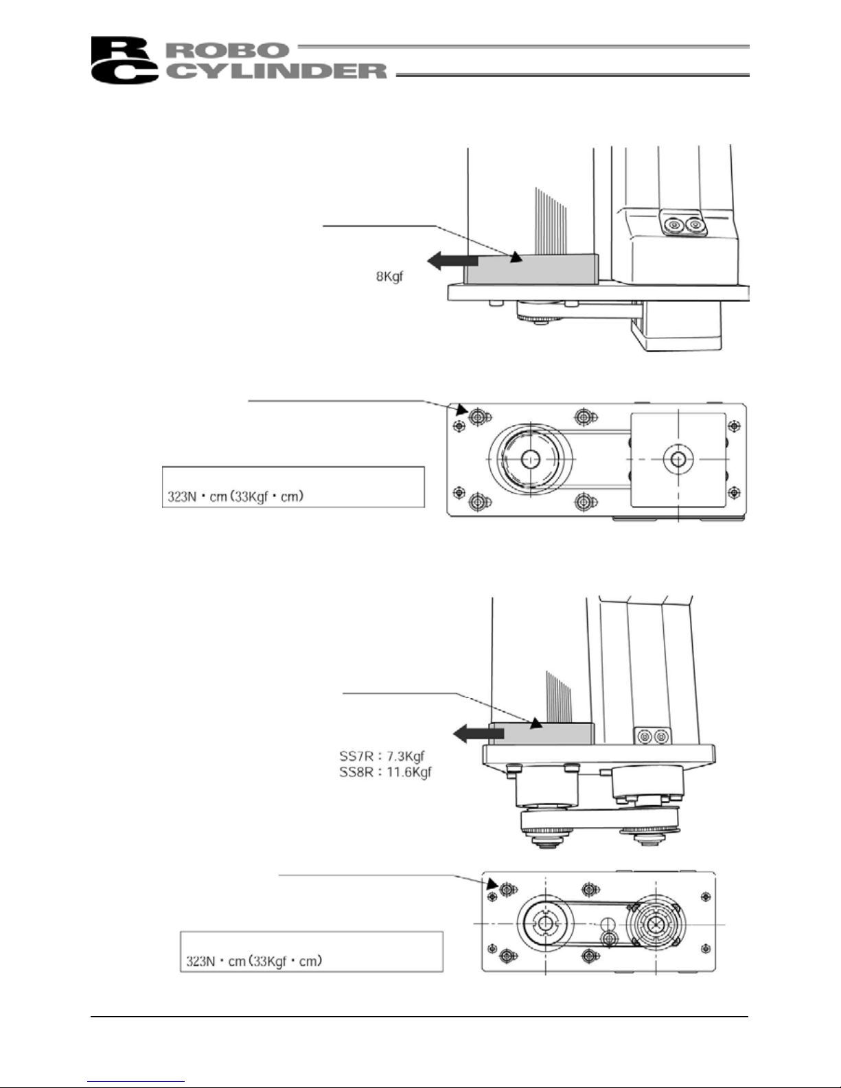
4) Loop a new belt over both pulleys.
5) Pass a looped strong string (or long tie-band) around the motor bracket and pull it with a tension gauge
to the specified tension. In this condition, uniformly tighten the adjusting bolts (hexagon socket-head
bolts: M4 × 20, 4 pcs.).
3) Remove the belt from the pulleys.
Tension: SS7R: 7.3kgf
SS8R/HS8R: 11.6kgf
Adjusting bolt tightening torque:
323N·cm (33kgf·cm)
Page 52

40
6) Install the pulley cover.
Tighten the thin-head screws (M4 × 6, 4 pcs.) using an Allen wrench of 2mm across flats.
Tightening torque: 204N·cm (20.8kgf·cm)
Page 53

41
11.9 Replacing the Motor
11.9.1 Motor Straight Type
●SA5C, SA6C
[Items Required for Replacement]
• Replacement motor NRC42* (with a coupling on the
motor shaft: see the photograph at the right)
• Allen wrench set
• Phillips screwdriver
• Grease (Kyodo Yushi’s Multemp LRL3 or equivalent)
[Procedure]
1) After removing the flat countersunk-head screws (M3 × 8, 2 pcs.) affixing the cable ends on the motor-end
cap, remove the pan-head screws affixing the motor-end cap.
2) Push in the cable-end molding to create a slack along the inner cable.
Push in the molding as far as possible.
• Pan-head screws (M3 × 80, 4 pcs.)
• Flat countersunk-head screws (M3 × 8, 2 pcs.)
3) Pull out the motor connector.
4) Pull out the encoder connector.
Caution: Do not apply a force to the
encoder by touching it directly.
Coupling
Page 54

42
Pilot alignment metal
If this metal is attached on the
decoupled motor, put it back to
the pilot on the actuator side.
Kyodo Yushi’s Multemp LRL3 has been
applied before shipment.
5) Remove the motor.
•
Remove the affixing bolts (M3 × 50, 2 pcs.) using
an Allen wrench of 2.5mm across flats.
• Pull out the motor by hand.
• Decoupled motor
6) Apply grease to the coupling on the actuator side.
Note: Never use any fluorine-based grease.
It will chemically react with
lithium-based
g
rease and damage the
Page 55

43
7) Install a new motor.
• After confirming that the angles of projections and depressions on the couplings are aligned, tighten the
affixing bolts (M3 × 50, 2 pcs.).
(Use an Allen wrench of 2.5mm across flats.)
Tightening torque: 59N·cm (6kgf·cm)
8) Connect the encoder connector.
9) Connect the motor connector.
Caution: Do not apply a force to the
encoder by touching it directly.
10) Replace the cable-end molding in the original position, and affi
x
it with the flat countersunk-head screws (M3 × 8, 2 pcs.).
Page 56

44
11) Affix the motor end cap with the pan-h ead screws (M3 × 80, 4 pcs.).
At this time, make sure not to pinch the cables.
Tightening torque: 61.5N·cm (6.3kgf·cm)
Page 57

45
●SA7C
[Items Required for Replacement]
• Replacement motor NRC56-* (with a coupling on the motor shaft; see the photograph below.)
• Allen wrench set • Phillips screwdriver
• Grease (Kyodo Yushi’s Multemp LRL3 or equivalent)
[Procedure]
1) After removing the flat countersunk-head screws (M3 × 8, 2 pcs.) affixing the cable ends on the motor end
cap, remove the pan-head screws (M3 × 105, 4 pcs.) affixing the motor end cap.
• Pan-head screws (M3 × 105, 4 pcs.)
• Flat countersunk-head screws (M3 × 8, 2 pcs.)
Coupling
Page 58

46
2) Push in the cable-end molding to create a slack along the inner cable.
Push in the molding as far as possible.
3) Pull out the motor connector.
4) Pull out the encoder connector.
Caution: Do not apply a force to the
encoder by touching it directly.
Page 59

47
Pilot alignment metal
If this metal is attached on the decoupled
motor, put it back to the pilot on the
actuator side.
Kyodo Yushi’s Multemp LRL3 has been
applied before shipment.
5) Remove the motor.
•
Remove the affixing bolts (M4 × 15, 4 pcs.) using an Allen wrench of 3mm across flats.
• Decoupled motor
6) Apply grease to the coupling on the actuator side.
Note: Never use any fluorine-based grease. It
will chemically react with lithium-based
g
rease and damage the actuator.
• Pull out the motor by hand.
Page 60

48
7) Install a new motor.
• After confirming that the angles of projections and depressions on the couplings are aligned, tighten the
affixing bolts (M4 × 15, 4 pcs.).
(Use an Allen wrench of 3mm across flats.)
Tightening torque: 176N·cm (18kgf·cm)
8) Connect the encoder connector.
9) Connect the motor connector.
Caution: Do not apply a force to the
encoder by touching it directly.
10) Replace the cable-end molding in the original position, and affi
x
it with the flat countersunk-head screws (M3 × 8, 2 pcs.).
Page 61

49
11) Affix the motor end cap with the pan-h ead screws (M3 × 105, 4 pcs.).
At this time, make sure not to pinch the cables.
Tightening torque: 61.5N·cm (6.3kgf·cm)
Page 62

50
●SS7C
[Items Required for Replacement]
• Replacement motor SSM42-* (with a coupling on the motor shaft; see the photograph below.)
• Allen wrench set • Phillips screwdriver
• Plastic hammer
[Procedure]
1) Remove the pan-head screws affixing the motor-end cap.
2) Remove the motor cover.
The motor cover is engaged with a positioning pin. If the cover does not come off easily, use a plastic
hammer to gently tap the motor cover from the side, and pull out the cover.
• Pan-head screws (M2 × 10, 2 pcs.)
• Pan-head screws (M3 × 95, 2 pcs.)
Coupling
Positioning pin
Page 63

51
3) Push in the motor-end cap into the motor cover.
4) Pull out the motor connector.
5) Pull out the encoder connector.
Caution: Do not apply a force to the
encoder by touching it directly.
Page 64

52
Motor flange
6) Remove the motor.
•
Remove the affixing bolts (M3 × 15, 2 pcs./M3 × 18, 2 pcs.) using an Allen wrench of 2.5mm
across flats.
• Decoupled motor
• Pull out the motor by hand.
• Remove the motor flange.
Remove the affixing bolts (M3 × 8, 4 pcs.) using an
Allen wrench of 2.5mm across flats.
Page 65

53
7) Install a new motor.
8) Connect the encoder connector.
9) Connect the motor connector.
Caution: Do not apply a force to the
encoder by touching it directly.
• Confirm that the angles of projections and
depressions on the couplings are aligned.
• Tighten the motor flange with the affixing
bolts (M3 × 8, 4 pcs.).
• First, tighten the right and left affixing bolts
(M3 × 18, 2 pcs.) uniformly.
• Next, tighten the upper affixing bolts (M3 ×
15, 2 pcs.) uniformly.
Tightening torque of M3 bolt: 83N·cm (8.5kgf·cm)
Page 66

54
11) Affix the motor cover.
• If the positioning pin does not go in smoothly, gently tap the
motor-end cap using a plastic hammer to push in the pin.
10) Pull out the motor-end cap from the motor cover and affix it with the
pan-head screws. At this time, make sure not to pinch the cables.
• Pan-head screws (M2 x 10, 2 pcs.)
• Pan-head screws (M3 × 105, 2 pcs.)
Tightening torque: 61.5N.cm (6.3kgf.cm)
Tightening torque: 61.5N·cm (6.3kgf·cm)
Tightening torque: 16.9N·cm (1.7kgf·cm)
Page 67
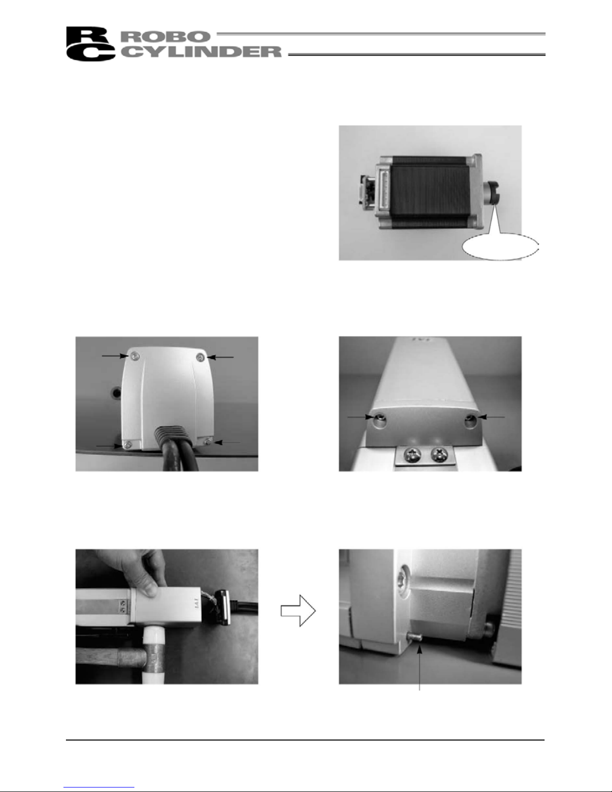
55
●SS8C, HS8C
[Items Required for Replacement]
• Replacement motor SSM56-* (for SS8C), HSM (for HS8C) (with a coupling on the motor shaft; see the
photograph below.)
• Allen wrench set • Phillips screwdriver
• Plastic hammer
[Procedure]
1) Remove the pan-head screws (M3 × 10,
4 pcs.) affixing the motor-end cap.
2) Remove the pan-head screws (M3 × 10,
2 pcs.) affixing the motor cover.
3) Remove the motor cover.
The motor cover is engaged with a positioning pin. If the cover does not come off easily, use a plastic
hammer to gently tap the motor cover from the side, and pull out the cover.
Coupling
Positioning pin
Page 68

56
4) Push in the motor-end cap into the motor cover.
5) Pull out the motor connector.
6) Pull out the encoder connector.
Caution: Do not apply a force to the
encoder by touching it directly.
Page 69

57
7) Remove the motor.
•
Remove the affixing bolts (M4 × 15, 4 pcs.) using an Allen wrench of 3mm across flats.
• Decoupled motor
• Pull out the motor by hand.
8) Install a new motor.
• After confirming that the angles of projections and depressions on the couplings are aligned, tighten the
affixing bolts (M4 × 15, 4 pcs.).
(Use an Allen wrench of 3mm across flats.)
Tightening torque: 176N·cm (18kgf·cm)
Page 70

58
Caution: Do not apply a force to the
encoder by touching it directly.
9) Connect the encoder connector.
10) Connect the motor connector.
11) Pull out the motor-end cap from the motor cover and affix it with the pan-head screws
(M3 × 105, 4 pcs.). At this time, make sure not to pinch the cables.
Tightening torque: 61.5N·cm (6.3kgf·cm)
12) Affix the motor cover.
• If the positioning pin does not go in
smoothly, gently tap the motor-end cap
using a plastic hammer to push in the pin.
• Tighten the pan-head screws (M3 x 10, 2 pcs.)
Tightening torque: 61.5N·cm (6.3kgf·cm)
Page 71

59
11.9.2 Motor Reversing Type
●SA5R, SA6R
[Items Required for Replacement]
• Replacement motor NRC423* (with a coupling on the motor shaft; see the photograph at the right)
• Allen wrench set • Phillips screwdriver
• Tension gauge (capable of tensioning to 3kgf or greater)
• Strong string, looped (or long tie-band)
[Procedure]
1) Remove the pulley cover.
Remove the four affixing thin-head screws using an Allen wrench of 1.5mm across flats.
2) Loosen the four tension adjusting bolts to
loosen the belt. (Use an Allen wrench of 2.5mm
across flats.)
3) Remove the belt from the pulleys.
Pulley
Page 72

60
4) Pull out the four tension adjusting bolts and two motor cover affixing bolts, and remove the motor unit.
Motor cover affixing bolts
6) Pull out the motor connector.
Motor cover affixing bolts
5) Remove the four pan-head screws affixing the motor-end cap of the motor unit, and pull out the motor.
7) Pull out the encoder connector.
Caution: Do not apply a force to the
encoder by touching it directly.
Page 73

61
8) Connect the encoder connector and motor connector to a new motor.
• Connection of the encoder connector • Connection of the motor connector
9) Couple the motor cover to the motor end cap with the affixing pan-head
screws (M3 × 6, 4 pcs.). At this time, make sure not to pinch the cables.
Caution: Do not apply a force to the
encoder by touching it directly.
10) Temporarily tighten the motor with the tension adjus ting bolts (hexagon socket-hea d screws: M3 ×
10, 4 pcs.) and loop the belt. In this condition, pass a looped strong string (or long tie-band) around
the motor-end flange, pull it with a tension gauge to the specified tension, and uniformly tighten the
adjusting bolts (hexagon socket-head bolts: M3 × 10, 4 pcs.).
(Use an Allen wrench of 2.5mm across flats.)
Tightening torque of M3 bolt:
61.5N·cm (6.27kgf·cm)
Tension: 2.5kgf
A
djusting bolt tightening torque:
162N·cm (16.5kgf·cm)
Page 74

62
11) Install the motor cover.
Tighten the hexagon socket-head screws (M3 × 12, 2 pcs.) using an Allen wrench of 2.5mm across flats.
Tightening torque: 83N·cm (8.47kgf·cm)
12) Install the pulley cover.
Tighten the thin-head screws (M3 × 6, 4 pcs.) using an Allen wrench of 1.5mm across flats.
Tightening torque: 87.2N·cm (8.90kgf·cm)
Page 75

63
●SA7R
[Items Required for Replacement]
• Replacement motor unit SSM561* (See the photograph at
the right.)
• Allen wrench set
• Tension gauge (capable of tensioning to 8kgf or greater)
• Strong string, looped (or long tie-band)
[Procedure]
1) Remove the pulley cover.
Remove the four affixing thin-head screws using an Allen wrench of 1.5mm across flats.
2) Loosen the four tension adjusting bolts to
loosen the belt. (Use an Allen wrench of 3mm
across flats.)
3) Remove the belt from the pulleys.
4) Pull out the tension adjusting bolts and remove the motor unit.
Page 76

64
5) Install a new motor unit and temporarily tighten it with the tension adjusting bolts (hexagon socket-head
screws: M4 × 20, 4 pcs.).
In this condition, loo
p
the reduction belt over the pulleys.
7) Tighten the thin-head screws (M3 × 6, 4 pcs.) using an Allen wrench of 1.5mm across flats.
6) Pass a looped strong string (or long tie-band) around the motor bracket and pull it with a tension gauge to
the specified tension. In this condition, uniformly tighten the adjusting bolts.
Tension: 8kgf
A
djusting bolt tightening torque:
323N·cm (33kgf·cm)
Tightening torque: 87.2N·cm (8.90kgf·cm)
Page 77

65
●SS7R, SS8R, HS8R
[Items Required for Replacement]
• Replacement motor unit SSM42-* (for SS7R), SSM561*
(for SS8R), HSM (for HS8R) (See the photograph at the
right.)
• Allen wrench set
• Tension gauge (capable of tensioning to 12kgf or greater)
• Strong string, looped (or long tie-band)
[Procedure]
1) Remove the pulley cover.
Remove the four affixing thin-head screws using an Allen wrench of 2mm across flats.
2) Loosen the four tension adjusting bolts to
loosen the belt. (Use an Allen wrench of 3mm
across flats.)
3) Remove the belt from the pulleys.
4) Pull out the tension adjusting bolts and remove the motor unit.
Page 78

66
5) Install a new motor unit and temporarily tighten it with the tension adjusting bolts (hexagon socket-head
screws: M4 × 20, 4 pcs.).
In this condition, loo
p
the reduction belt over the pulleys.
7) Install the pulley cover.
Tighten the thin-head screws (M4 × 6, 4 pcs.) using an Allen wrench of 2mm across flats.
6) Pass a looped strong string (or long tie-band) around the motor bracket and pull it with a tension gauge to
the specified tension. In this condition, uniformly tighten the adjusting bolts.
Tension: SS7R 7.3kgf, SS8R/HS8R 11.6kgf
A
djusting bolt tightening torque:
323N·cm (33kgf·cm)
Tightening torque: 204N·cm (20.8kgf·cm)
Page 79

67
Appendix · How to use the home mark
How to use the home mark
◆
Please affix these marks to the actuator as home markers as needed.
Appendix
Contents of sticker
Home mark sticke
r
× 1 sheet
Home mark scale × 4 Home mark × 4
(Scale: 1mm graduation mark, 10mm width)
•
Peel off the home marks and use as a base sheet.
Note 1. Every mark has an adhesive back.
2. Remove smears and stains from the surface before affixing the marks.
3. Avoid labels or nameplates as a marking location.
Example of Use
[1] Used as home position
On the slider
Motor
Motor
On the slider
On the base
•
Place the two marks when the actuator is stopped at the home position.
[2] Used as stop positions
A
t stop positions on the base
Page 80

Catalog No.: MJ3660-1A
IAI America Inc.
Head Office: 2690W 237th Street Torrance, CA 90505
TEL (310) 891-6015 FAX (310) 891-0815
Chicago Office: 1261 Hamilton Parkway Itasca, IL 60143
TEL (630) 467-9900 FAX (630) 467-9912
Atlanta Office: 1220-E Kenneston Circle, Marrietta, GA 30066
TEL (678) 354-9470 FAX (678) 354-9471
Home page: www.intelligentactuator.com
IAI Industrieroboter GmbH
Ober der Röth 4, D-65824 Schwalbach am Taunus, Germany
TEL 06196-88950 FAX 06196-889524
The prices, specifications, dimensions and other information provided in this manual are subject to change without notice for
purposes of product improvement.
Copyright © 2006 Oct. IAI Corporation. All rights reserved.
 Loading...