

Page 1

DSEP Controller
ASEP Controller
PSEP Controller
Instruction Manual Tenth Edition
/
Page 2

Page 3

/
[Important]
This Instruction Manual is original.
The product cannot be operated in any way unless expressly specifi ed in this Instruction Manual.
IAI shall assume no responsibility for the outcome of any operation not specifi ed herein.
Information contained in this Instruction Manual is subject to change without notice for the purpose
of product improvement.
If you have any question or comment regarding the content of this manual, please contact the IAI
sales offi ce near you.
Using or copying all or part of this Instruction Manual without permission is prohibited.
The company names, names of products and trademarks of each company shown in the
sentences are registered trademarks.
Please Read Before Use
Thank you for purchasing our product.
This Instruction Manual describes all necessary information items to operate this product safely such as
the operation procedure, structure and maintenance procedure.
Before the operation, read this manual carefully and fully understand it to operate this product safely. The
enclosed CD/DVD in this product package includes the Instruction Manual for this product.
For the operation of this product, print out the necessary sections in the Instruction Manual or display
them using the personal computer.
After reading through this manual, keep this Instruction Manual at hand so that the operator of this
product can read it whenever necessary.
Page 4

/
Page 5

/
Table of Contents
Safety Guide .............................................................................................................................1
International Standards Compliances .....................................................................................8
CE Marking ...............................................................................................................................9
Precautions in Operation .......................................................................................................10
Name for Each Parts and Their Functions ............................................................................14
Actuator Axes .........................................................................................................................16
Starting Procedures ...............................................................................................................18
1. Specifi cations Check ......................................................................................................19
1.1 Product Check ..................................................................................................................................19
1.1.1 Parts …………………………………………………………………………………………… 19
1.1.2 Teaching Tool (to be purchased separately) ………………………………………………… 19
1.1.3 Instruction manuals related to this product, which are contained in the
instruction manual (CD/DVD). ……………………………………………………………… 20
1.1.4 How to read the model plate ………………………………………………………………… 20
1.1.5 How to read the model of the controller ……………………………………………………… 20
1.2 Basic Specifi cations .........................................................................................................................22
1.3 External Dimensions ........................................................................................................................24
1.4 I/O Specifi cations .............................................................................................................................25
1.4.1 PIO Input and Output Interface ……………………………………………………………… 25
1.5 Installation Environment...................................................................................................................26
1.6 Installation and Noise Elimination ...................................................................................................27
2. Wiring ..............................................................................................................................29
2.1 Wiring Diagram (Connection of construction devices) ...................................................................29
2.2 PIO Pattern Selection and PIO Signal ............................................................................................30
2.3 Circuit Diagram (Example) ..............................................................................................................35
2.4 Wiring Method ..................................................................................................................................41
2.4.1 Wiring Layout of Power Supply Connector ………………………………………………… 41
2.4.2 Wiring Layout of FG Terminal Block ………………………………………………………… 42
2.4.3 Connection to Actuator ……………………………………………………………………… 43
2.4.4 Connection of PIO …………………………………………………………………………… 44
2.4.5 SIO Connector Connection …………………………………………………………………… 45
2.4.6 Battery Connector Connection (For Simple Absolute Type) ……………………………… 46
Page 6

/
3. Operation .........................................................................................................................48
3.1 Setting ...............................................................................................................................................48
3.1.1 Initial Setting …………………………………………………………………………………… 48
3.1.2 Position Data Setting ………………………………………………………………………… 50
3.1.3 Absolute Reset
(This function is effective only when the controller and actuator are the absolute type). … 54
3.2 Power-up and PIO Control ..............................................................................................................55
3.2.1 Control of Input Signal ………………………………………………………………………… 55
3.2.2 Power Input …………………………………………………………………………………… 56
3.2.3 Home-return …………………………………………………………………………………… 57
3.3 Timing Chart .....................................................................................................................................58
3.4 User Parameters ..............................................................................................................................63
3.5 Servo Adjustment .............................................................................................................................65
3.5.1 Adjustment for ASEP and PSEP …………………………………………………………… 65
3.5.2 Adjustment for DSEP ………………………………………………………………………… 66
3.5.3 Servo Parameter ……………………………………………………………………………… 68
3.6 Alarm.................................................................................................................................................69
3.6.1 Alarm Level …………………………………………………………………………………… 69
3.6.2 Alarm Codes and Trouble Shooting ………………………………………………………… 70
4. Appendix .........................................................................................................................75
4.1 List of Specifi cations of Connectable Actuators ..............................................................................75
4.2 Pressing Force and Current Limit Value .........................................................................................99
5. Warranty ........................................................................................................................106
5.1 Warranty Period .............................................................................................................................106
5.2 Scope of Warranty .........................................................................................................................106
5.3 Honoring the Warranty ...................................................................................................................106
5.4 Limited Liability ...............................................................................................................................106
5.5 Conditions of Conformance with Applicable Standards/Regulations, Etc., and Applications .....107
5.6 Other Items Excluded from Warranty ............................................................................................107
Change History .....................................................................................................................108
Page 7

1
/
Safety Precautions for Our Products
The common safety precautions for the use of any of our robots in each operation.
No.
Operation
Description
Description
1 Model Selection ● This product has not been planned and designed for the application
where high level of safety is required, so the guarantee of the protection of
human life is impossible. Accordingly, do not use it in any of the following
applications.
1) Medical equipment used to maintain, control or otherwise affect human
life or physical health.
2) Mechanisms and machinery designed for the purpose of moving or
transporting people (For vehicle, railway facility or air navigation facility)
3) Important safety parts of machinery (Safety device, etc.)
● Do not use the product outside the specifi cations. Failure to do so may
considerably shorten the life of the product.
● Do not use it in any of the following environments.
1) Location where there is any infl ammable gas, infl ammable object or
explosive
2) Place with potential exposure to radiation
3) Location with the ambient temperature or relative humidity exceeding
the specifi cation range
4) Location where radiant heat is added from direct sunlight or other large
heat source
5) Location where condensation occurs due to abrupt temperature
changes
6) Location where there is any corrosive gas (sulfuric acid or hydrochloric
acid)
7) Location exposed to signifi cant amount of dust, salt or iron powder
8) Location subject to direct vibration or impact
● For an actuator used in vertical orientation, select a model which is
equipped with a brake. If selecting a model with no brake, the moving part
may drop when the power is turned OFF and may cause an accident such
as an injury or damage on the work piece.
Safety Guide
“Safety Guide” has been written to use the machine safely and so prevent personal injury or property
damage beforehand. Make sure to read it before the operation of this product.
Page 8

2
/
No.
Operation
Description
Description
2 Transportation ● When carrying a heavy object, do the work with two or more persons or
utilize equipment such as crane.
● When the work is carried out with 2 or more persons, make it clear who is
to be the leader and who to be the follower(s) and communicate well with
each other to ensure the safety of the workers.
● When in transportation, consider well about the positions to hold, weight
and weight balance and pay special attention to the carried object so it
would not get hit or dropped.
● Transport it using an appropriate transportation measure.
The actuators available for transportation with a crane have eyebolts
attached or there are tapped holes to attach bolts. Follow the instructions
in the instruction manual for each model.
● Do not step or sit on the package.
● Do not put any heavy thing that can deform the package, on it.
● When using a crane capable of 1t or more of weight, have an operator
who has qualifi cations for crane operation and sling work.
● When using a crane or equivalent equipments, make sure not to hang a
load that weighs more than the equipment’s capability limit.
● Use a hook that is suitable for the load. Consider the safety factor of the
hook in such factors as shear strength.
● Do not get on the load that is hung on a crane.
● Do not leave a load hung up with a crane.
● Do not stand under the load that is hung up with a crane.
3 Storage and
Preservation
● The storage and preservation environment conforms to the installation
environment. However, especially give consideration to the prevention of
condensation.
● Store the products with a consideration not to fall them over or drop due to
an act of God such as earthquake.
4 Installation and
Start
(1) Installation of Robot Main Body and Controller, etc.
● Make sure to securely hold and fi x the product (including the work part). A
fall, drop or abnormal motion of the product may cause a damage or injury.
Also, be equipped for a fall-over or drop due to an act of God such as
earthquake.
● Do not get on or put anything on the product. Failure to do so may
cause an accidental fall, injury or damage to the product due to a drop
of anything, malfunction of the product, performance degradation, or
shortening of its life.
● When using the product in any of the places specifi ed below, provide a
suffi cient shield.
1) Location where electric noise is generated
2) Location where high electrical or magnetic fi eld is present
3) Location with the mains or power lines passing nearby
4) Location where the product may come in contact with water, oil or
chemical droplets
Page 9

3
/
No.
Operation
Description
Description
4 Installation and
Start
(2) Cable Wiring
● Use our company’s genuine cables for connecting between the actuator
and controller, and for the teaching tool.
● Do not scratch on the cable. Do not bend it forcibly. Do not pull it. Do not
coil it around. Do not insert it. Do not put any heavy thing on it. Failure to
do so may cause a fi re, electric shock or malfunction due to leakage or
continuity error.
● Perform the wiring for the product, after turning OFF the power to the unit,
so that there is no wiring error.
● When the direct current power (+24V) is connected, take the great care of
the directions of positive and negative poles. If the connection direction is
not correct, it might cause a fi re, product breakdown or malfunction.
● Connect the cable connector securely so that there is no disconnection or
looseness. Failure to do so may cause a fi re, electric shock or malfunction
of the product.
● Never cut and/or reconnect the cables supplied with the product for the
purpose of extending or shortening the cable length. Failure to do so may
cause the product to malfunction or cause fi re.
(3) Grounding
● The grounding operation should be performed to prevent an electric shock
or electrostatic charge, enhance the noise-resistance ability and control
the unnecessary electromagnetic radiation.
● For the ground terminal on the AC power cable of the controller and the
grounding plate in the control panel, make sure to use a twisted pair cable
with wire thickness 0.5mm
2
(AWG20 or equivalent) or more for grounding
work. For security grounding, it is necessary to select an appropriate
wire thickness suitable for the load. Perform wiring that satisfi es the
specifi cations (electrical equipment technical standards).
● Perform Class D Grounding (former Class 3 Grounding with ground
resistance 100Ω or below).
Page 10

4
/
No.
Operation
Description
Description
4 Installation and
Start
(4) Safety Measures
● When the work is carried out with 2 or more persons, make it clear who is
to be the leader and who to be the follower(s) and communicate well with
each other to ensure the safety of the workers.
● When the product is under operation or in the ready mode, take the safety
measures (such as the installation of safety and protection fence) so that
nobody can enter the area within the robot’s movable range. When the
robot under operation is touched, it may result in death or serious injury.
● Make sure to install the emergency stop circuit so that the unit can be
stopped immediately in an emergency during the unit operation.
● Take the safety measure not to start up the unit only with the power turning
ON. Failure to do so may start up the machine suddenly and cause an
injury or damage to the product.
● Take the safety measure not to start up the machine only with the
emergency stop cancellation or recovery after the power failure. Failure
to do so may result in an electric shock or injury due to unexpected power
input.
● When the installation or adjustment operation is to be performed, give
clear warnings such as “Under Operation; Do not turn ON the power!” etc.
Sudden power input may cause an electric shock or injury.
● Take the measure so that the work part is not dropped in power failure or
emergency stop.
● Wear protection gloves, goggle or safety shoes, as necessary, to secure
safety.
● Do not insert a fi nger or object in the openings in the product. Failure to do
so may cause an injury, electric shock, damage to the product or fi re.
● When releasing the brake on a vertically oriented actuator, exercise
precaution not to pinch your hand or damage the work parts with the
actuator dropped by gravity.
5 Teaching ● When the work is carried out with 2 or more persons, make it clear who is
to be the leader and who to be the follower(s) and communicate well with
each other to ensure the safety of the workers.
● Perform the teaching operation from outside the safety protection
fence, if possible. In the case that the operation is to be performed
unavoidably inside the safety protection fence, prepare the “Stipulations
for the Operation” and make sure that all the workers acknowledge and
understand them well.
● When the operation is to be performed inside the safety protection fence,
the worker should have an emergency stop switch at hand with him so that
the unit can be stopped any time in an emergency.
● When the operation is to be performed inside the safety protection fence,
in addition to the workers, arrange a watchman so that the machine can
be stopped any time in an emergency. Also, keep watch on the operation
so that any third person can not operate the switches carelessly.
● Place a sign “Under Operation” at the position easy to see.
● When releasing the brake on a vertically oriented actuator, exercise
precaution not to pinch your hand or damage the work parts with the
actuator dropped by gravity.
* Safety protection Fence : In the case that there is no safety protection
fence, the movable range should be indicated.
Page 11

5
/
No.
Operation
Description
Description
6 Trial Operation ● When the work is carried out with 2 or more persons, make it clear who is
to be the leader and who to be the follower(s) and communicate well with
each other to ensure the safety of the workers.
● After the teaching or programming operation, perform the check operation
one step by one step and then shift to the automatic operation.
● When the check operation is to be performed inside the safety protection
fence, perform the check operation using the previously specifi ed work
procedure like the teaching operation.
● Make sure to perform the programmed operation check at the safety
speed. Failure to do so may result in an accident due to unexpected
motion caused by a program error, etc.
● Do not touch the terminal block or any of the various setting switches in
the power ON mode. Failure to do so may result in an electric shock or
malfunction.
7 Automatic
Operation
● Check before starting the automatic operation or rebooting after operation
stop that there is nobody in the safety protection fence.
● Before starting automatic operation, make sure that all peripheral
equipment is in an automatic-operation-ready state and there is no alarm
indication.
● Make sure to operate automatic operation start from outside of the safety
protection fence.
● In the case that there is any abnormal heating, smoke, offensive smell,
or abnormal noise in the product, immediately stop the machine and turn
OFF the power switch. Failure to do so may result in a fi re or damage to
the product.
● When a power failure occurs, turn OFF the power switch. Failure to do so
may cause an injury or damage to the product, due to a sudden motion of
the product in the recovery operation from the power failure.
Page 12

6
/
No.
Operation
Description
Description
8 Maintenance
and Inspection
● When the work is carried out with 2 or more persons, make it clear who is
to be the leader and who to be the follower(s) and communicate well with
each other to ensure the safety of the workers.
● Perform the work out of the safety protection fence, if possible. In the
case that the operation is to be performed unavoidably inside the safety
protection fence, prepare the “Stipulations for the Operation” and make
sure that all the workers acknowledge and understand them well.
● When the work is to be performed inside the safety protection fence,
basically turn OFF the power switch.
● When the operation is to be performed inside the safety protection fence,
the worker should have an emergency stop switch at hand with him so that
the unit can be stopped any time in an emergency.
● When the operation is to be performed inside the safety protection fence,
in addition to the workers, arrange a watchman so that the machine can
be stopped any time in an emergency. Also, keep watch on the operation
so that any third person can not operate the switches carelessly.
● Place a sign “Under Operation” at the position easy to see.
● For the grease for the guide or ball screw, use appropriate grease
according to the Instruction Manual for each model.
● Do not perform the dielectric strength test. Failure to do so may result in a
damage to the product.
● When releasing the brake on a vertically oriented actuator, exercise
precaution not to pinch your hand or damage the work parts with the
actuator dropped by gravity.
● The slider or rod may get misaligned OFF the stop position if the servo
is turned OFF. Be careful not to get injured or damaged due to an
unnecessary operation.
● Pay attention not to lose the cover or untightened screws, and make sure
to put the product back to the original condition after maintenance and
inspection works.
Use in incomplete condition may cause damage to the product or an injury.
* Safety protection Fence : In the case that there is no safety protection
fence, the movable range should be indicated.
9 Modifi cation and
Dismantle
● Do not modify, disassemble, assemble or use of maintenance parts not
specifi ed based at your own discretion.
10 Disposal ● When the product becomes no longer usable or necessary, dispose of it
properly as an industrial waste.
● When removing the actuator for disposal, pay attention to drop of
components when detaching screws.
● Do not put the product in a fi re when disposing of it.
The product may burst or generate toxic gases.
11 Other ● Do not come close to the product or the harnesses if you are a person who
requires a support of medical devices such as a pacemaker. Doing so may
affect the performance of your medical device.
● See Overseas Specifi cations Compliance Manual to check whether
complies if necessary.
● For the handling of actuators and controllers, follow the dedicated
instruction manual of each unit to ensure the safety.
Page 13

7
/
Alert Indication
The safety precautions are divided into “Danger”, “Warning”, “Caution” and “Notice” according to the
warning level, as follows, and described in the Instruction Manual for each model.
Level Degree of Danger and Damage Symbol
Danger
This indicates an imminently hazardous situation which, if the
product is not handled correctly, will result in death or serious
injury.
Danger
Warning
This indicates a potentially hazardous situation which, if the
product is not handled correctly, could result in death or serious
injury.
Warning
Caution
This indicates a potentially hazardous situation which, if the
product is not handled correctly, may result in minor injury or
property damage.
Caution
Notice
This indicates lower possibility for the injury, but should be kept to
use this product properly.
Notice
Page 14

8
/
ASEP/PSEP and DSEP comply with the following international standards:
RoHS Directive CE Marking UL
(Note)
○○○
(Note) The DSEP is not applicable to UL.
International Standards Compliances
Page 15

9
/
CE Marking
If a compliance with the CE Marking is required, please follow Overseas Standards Compliance
Manual (ME0287) that is provided separately.
Page 16

10
/
Precautions in Operation
1. Use the following teaching tools.
Use the teaching tool such as the PC software stated in the next clause as the applicable for this
controller.
● Teaching Tools that is applicable for this controller
[Refer to 1.2.2]
2. Backup the data to secure for breakdown.
A non-volatile memory is used as the backup memory for this controller. All the registered
position data and parameters are written into this memory and backed-up at the same time.
Therefore, you will not usually lose the data even if the power is shut down. However, make sure
to save the latest data so a quick recovery action can be taken in case when the controller is
broken and needs to be replaced with another one.
How to Save Data
(1) Save the data to CD-R or hard disk with using the PC software
(2) Hard-copy the information of position tables and parameters on paper
3. Set the operation patterns.
This controller possesses 6 types of control logics to meet various ways of usage, and changes
the role of each PIO signal following the selected control logic.
The setup can be performed in the initial setting.
[Refer to 2.1]
The PIO pattern is set to “0” (Standard Point-to-Point Movement) when the unit is delivered. Set
the operation pattern setting to the logic that suits to your use after the power is turned on.
Warning:
Please note it is very risky when the control sequence and PIO pattern setting do not match to each
other. It may not only cause the normal operation disabled, but also may cause an unexpected
movement.
Page 17

11
/
4. Operation cannot be performed unless there is an input of Servo-on
Signal and Pause Signal.
(1) Servo-on Signal (SON)
Servo-on signal (SON) is selectable from either “Enable” or “Disable” by the setting.
It is settable in the initial setting.
[Refer to 2.1 Setting]
If it is set to “Enable”, the actuator would not operate unless turning this signal on.
If it is set to “Disable”, the servo becomes on and the actuator operation becomes enabled
as soon as the power supply to the controller is turned on and the emergency stop signal is
cancelled.
[Refer to 2.1 Setting]
It is set to “Disable” when the unit is delivered. Have the setting that suits to the desirable control
logic.
(2) Pause Signal (*STP)
The input signal of the pause signal (*STP) is always on considering the safety. Therefore, in
general, the actuator would not operate if this signal is not on.
It is available to make this signal to “Not to use”, if this signal is undesirable.
It is settable in the initial setting.
[Refer to 2.1 Setting]
If it is set to “Not to use”, the actuator operation is available even without this signal being on.
It is set to “Not to use” when the unit is delivered.
5. Rotary actuator cannot be set to Multi-Rotation Specifi cation.
Rotary actuator cannot be set to Multi-Rotation Specifi cation since the index mode setting cannot
be performed.
Page 18

12
/
Output
Process
Input
Process
6. Transference of PIO Signal between Controllers
Please note the following when conducting transference of PIO signal between controllers.
To certainly transfer the signal between controllers with different scan time, it is necessary to
have longer scan time than the one longer than the other controller. To ensure to end the process
safely, it is recommended to have the timer setting more than twice as long as the longer scan
time at least.
● Operation Image
PLC
(e.g. scan time is 20msec)
Also, if one tries to read the signal that is being re-written by the other, the signal may be read wrongly.
Make sure to read the signal after the rewriting is complete. (It is recommended to have more than 2
scan periods to wait.) Make sure not to have the output side to change the output until the other side
completes the reading. Also, a setting is made on the input area not to receive the signal less than a
certain time to prevent a wrong reading of noise. This duration also needs to be considered.
This controller
(scan time 1msec)
As shown in the diagram, the input and output
timings of two devices that have different scan
time do not match, of course, when transferring
a signal.
There is no guarantee that PLC would read the
signal as soon as this controller signal turns on.
In such a case, make the setting to read the
signal after a certain time that is longer than the
longer scan time to ensure the reading process
to succeed on the PLC side.
It is the same in the case this controller side
reads the signal.
In such a case, it is recommended to ensure 2
to 4 times of the scan time for the timer setting
margin.
It is risky to have the setting below the scan
time since the timer is also processed in the
scan process.
In the diagram, PLC can only read the input
once in 20msec even though this controller
output once in 1msec.
Because PLC only conducts output process
once in 20msec, this controller identifi es the
same output status for that while.
Page 19

13
/
7. PLC Timer Setting
Do not have the PLC timer setting to be done with the minimum setting.
Setting to “1” for 100msec timer turns on at the timing from 0 to 100msec while 10msec timer
from 0 to 10msec for some PLC.
Therefore, the same process as when the timer is not set is held and may cause a failure such
as the actuator cannot get positioned to the indicated position number in Positioner Mode.
Set “2” as the minimum value for the setting of 10msec timer and when setting to 100msec, use
10msec timer and set to “10”.
8. Cautions when turning Servo on (for ASEP/PSEP)
The magnetic pole phase detection may not be performed normally if the servo is turned on near
the mechanical end, and may cause such problems like an abnormal operation, magnetic pole
not being defi ned or electromagnetic detection error.
Put it away from the mechanical end when turning the servo on.
9. Make sure to follow the usage condition, environment and
specifi cations of the product.
Not doing so may cause a drop of performance or malfunction of the product.
Page 20

14
/
1) Battery Connector (It is not equipped for Incremental Type and DSEP)
If Absolute Type actuator, it is the battery connector for absolute data retention.
2) LED for ABS (It is not equipped for Incremental Type and DSEP)
Following shows the absolute data retention battery status:
Signal Indication Status Description
2
Green Light is turned ON. System Normal
Red Light is turned ON. System abnormality
1
Green Light is turned ON Absolute Unit Reset Complete (ST2 lighting ON in Green)
Red Light is turned ON.
• Absolute Unit Reset Incomplete (ST2 lighting ON in Green)
• Hardware Error (ST2 lighting ON in Red)
0
Green Light is turned ON Battery Fully Charged
Orange Light is turned ON. In Battery Charging Operation
Red Light is turned ON. Battery Disconnected
Name for Each Parts and Their Functions
Pictures show ASEP, It should be the same for PSEP and DSEP.
1) Battery Connector
(It is not equipped
for Incremental Type and DSEP)
2) LED for ABS
(It is not equipped
for Incremental Type and DSEP)
3) StatusLED
(for SV, ALM and EMG)
4) SIO Connector
5) PIO Connector
6) Motor · Encoder
Connector
7) Power Supply
Connector
8) FG Terminal Block
Page 21

15
/
Pin No. Signal Description
5BK
For Brake Forced Release Power Supply (ASEP/PSEP)
Keep DSEP disconnected.
4 MP Motor Driving Power Supply
3 24V Positive side of the 24V power supply
2 0V Negative side of the 24V power supply
1 EMG EMG’s Confi rmation Signal
8) FG Terminal Block
It is the connector to connect the protection ground. Make sure to conduct the Class D grounding
(formerly Class 3 grounding: grounding resistance at 100 or less)
BK
MP
24V
0V
EMG
3) StatusLED (For SV, ALM and EMG)
Following show the controller operation status:
Indication Status Description
SYS
Green Light is turned ON. Servo ON Status
Light is turned OFF Servo OFF Status
Flashing in green (1Hz) Servo ON Status
Red Light is turned ON. In the alarm issue or emergency stop
4) SIO Connector
It is the connector for the connection of the communication cables for the teaching pendant and
PC software.
5) PIO Connector
It is the connector for 24V DC I/O signal connection.
6) Motor · Encoder Connector
It is the connector to connect the actuator motor · encoder cable.
7) Power Supply Connector
It is the connector to supply the power to the controller and to the control board.
Page 22

16
/
Actuator Axes
Refer to the pictures below for the actuator axes that can be controlled by ASEP/PSEP and DSEP.
(There are some types that cannot be controlled depending on the controller. Check the catalog for
the details.)
0 defi nes the home position, and items in ( ) are for the home-reversed type (option).
(1) Rod Type
(2) Slider Type
(3) Table Type
(4) Arm Type
Page 23

17
/
(5) Gripper Type
0
0
0
+
+
+
Finger Attachment
(Note)
00
++
Finger Attachment
(Note)
Note: Finger attachment is not included in the actuator package. Please prepare separately.
(6) Rotary Type
0
+−
330
°
(330° Rotation Specification)
(Multi-Rotation Specification)
Page 24

18
/
When using this product for the fi rst time, make sure to avoid mistakes and incorrect wiring by referring to
the procedure below.
Installation and Wiring
Perform the installation of and wiring for the controller and
actuator according to the instructions in the Instruction
Manual for the actuator and this Instruction Manual.
Contact our distributor or us.
↓Yes
←
Check Item
Does the STATUS indicator LED light ON in red?
Check of Safety Circuit
Check that the emergency stop circuit (or motor drivepower
cutoff circuit) operates normally to turn off the servo.
Check the emergency stop circuit.
Set-up for operation is completed,
Perform the system operation adjustment.
Servo ON
Turn ON the servo-motor on the PC Software unit or touch panel teaching unit
and confirm that the STATUS indicator LED lights ON in green (SVON).
(Note) If the servo-on control is disabled in the initial setting, the controller
automatically turns the servo on.
Check of Packed Items
Are there all the delivered items?
↓
No→
↓
Target Position Setting
Set the parameters for those such as “Backward Position”, “Forward Position”, “Intermediate Position” and “Speed” (which differ
for each PIO pattern) in the position table on the PC software or the position setting on the touch panel teaching.
↓Yes
↓No
→
→
→
→
No→
Point Check Item
• Have you performed the installation and the connection
of the frame ground and protective ground?
• Has the noise countermeasure been taken?
Power Supply and Alarm Check
Connect the PC Software unit or touch panel
teaching unit and turn ON the power to the unit.
Confirm that the emergency stop switch has been
cancelled. When the switch has been cancelled,
confirm the alarm description using the PC Software
unit or touch panel teaching unit and settle it.
Yes
←No
No
←
Yes
Confirm the alarm description using
the PC Software unit or touch panel
teaching unit and settle it.
No→
Yes
Trial Run Adjustment
Perform the performance check on the Position Table
in the PC software or on the “Performance Check” window
(Sequence: “Touch panel teaching” → “Initial Setting” ).
↓
Is there any vibration
or abnormal noise?
→→
Confirm that there is no problem
in the actuator installation or the
actuator operation condition
demands more than the rated
voltage.
Yes
Perform the initial setting according
to the instructions on the window. [Refer to Section
2.1 Setting
]
[Refer to the Instruction Manual for the PC software or touch panel teaching]
Have you completed the initial settings?
Warning : Turning the servo on near the mechanical end may disturb the
magnetic pole phase detection work properly, and may cause
such problems as an abnormal operation, the magnetic pole
unconfirmed error or the excitation detection error.
Put away from the mechanical end when turning the servo on.
Caution : In the case the actuator is installed in vertical orientation,the
actuator may get slightly dropped by self-weight if servo on and off
is repeatedly performed. Be careful not to pinch the hand or
damage the work.
Starting Procedures
Page 25

19
/
1. Specifi cations Check
1. Specifi cations Check
1.1 Product Check
This product is comprised of the following parts if it is of standard confi guration.
If you fi nd any fault in the contained model or any missing parts, contacts us or our distributer.
1.1.1 Parts
No. Part Name Model
1 Controller [Refer to “1.1.4 How to read the model plate”]
Accessories
2 I/O Flat Cable
Standard type CB-APSEP-PIO*** (***shows the cable length)
Dust-proof type
(Equivalent to IP53)
CB-APSEPW-PIO*** (***shows the cable length)
3 Power Connector MC1.5/5-ST-3.5 (PHOENIX CONTACT)
4 Spacer PFP-S (OMRON)
5
Absolute Battery Unit
(For Simple Absolute Type Only)
SEP-ABUM (Standard type)
SEP-ABUM-W (Dust-proof type)
6 Instruction Manual (This Manual)
7 Instruction Manual (CD/DVD)
8 Safety Guide
1.1.2 Teaching Tool (to be purchased separately)
For the setups such as position setting and parameter setting using the teaching operation, the teaching tool
is required. Please prepare either of the following teaching tools.
No. Part Name Model
1
PC Software (Includes RS232C Exchange Adapter External Machine
Communication Cable)
RCM-101-MW
2
PC Software (Includes USB Exchange Adapter USB Cable External
Machine Communication Cable)
RCM-101-USB
3
Teaching Pendant (Touch Panel Teaching)
CON-PTA
4
Teaching Pendant (Touch panel teaching equipped with a dead man’s
switch)
CON-PDA
5
Teaching Pendant (Touch panel teaching equipped with a dead man’s
switch TP adapter (RCB-LB-TG))
CON-PGA
6
Teaching Pendant dedicated for SEP Controller (Touch Panel Teaching)
SEP-PT
7
Teaching Pendant (Touch Panel Teaching)
CON-PT
(Note 1)
8
Teaching Pendant (Touch panel teaching equipped with a dead man’s
switch)
CON-PD
(Note 1)
9
Teaching Pendant (Touch panel teaching equipped with a dead man’s
switch TP adapter (RCB-LB-TG))
CON-PG
(Note 1)
Note 1) It is not applied for DSEP.
Page 26

20
/
1. Specifi cations Check
1.1.3 Instruction manuals related to this product, which are contained in the
instruction manual (CD/DVD).
No Name Manual No.
1 ASEP/PSEP/DSEP Instruction Manual ME0267
2 PC Software RCM-101-MW/RCM-101-USB Instruction Manual ME0155
3 Touch Panel Teaching CON-PTA/PDA/PGA Instruction Manual ME0294
4
Teaching Pendant dedicated for SEP Controller (Touch Panel Teaching)
Instruction Manual
ME0217
1.1.4 How to read the model plate
Model
Serial number
1.1.5 How to read the model of the controller
<Detail of Connected Axis>
[Motor Type]
<Identification for IAI use only>
* There is no identification in some cases.
<Applicable to Simplified Absolute Unit>
ABU
ABUN
No description
(Note) ABU and ABUN are the already existing
models, which do not comply with UL.
<Power-supply Voltage>
0 : 24V DC
<I/O Cable Length>
0 : No Cable 3 : 3m
2:2m 5 :5m
<I/O Signal Pattern>
NP : NPN Specification
(Sync. Type) (Standard)
PN : PNP Specification
(Source Type)
:
Simple Absolute Type
(with the Absolute Battery Unit)
:
Simple Absolute Type
(with no Absolute Battery Unit)
:
Incremental Type
2W
5W
10W
20W
:
:
:
:
20W
(For RCA-R□3, SRA4, RCA2-SA4/TA5)
30W::
20S
30
[Encoder Type]
I : Incremental
[Option]
LA : Power Consumption Type
HA : High Acceleration/Deceleration Type
2
5
10
20
[ASEP]
<Series>
<Type>
C : Standard type
CW : Dust-proof type
(Equivalent to IP53)
ASEP – C – 20ILA – NP – 0 – 0 – ABU – **
Page 27

21
/
1. Specifi cations Check
<Detail of Connected Axis>
[Motor Type]
[Encoder Type]
I : Incremental
* It is not the absolute type.
<Identification for IAI use only>
* There is no identification in some cases.
<Power-supply Voltage>
0 : 24V DC
<I/O Cable Length>
0 : No Cable 3 : 3m
2 : 2m 5 : 5m
<I/O Signal Pattern>
NP : NPN Specification
(Sync. Type) (Standard)
PN : PNP Specification
(Source Type)
3W:3
[DSEP]
<Series>
<Type>
C : Standard type
CW : Dust-proof type
DSEP – C – 3I – NP – 0 – 0 – **
<Identification for IAI use only>
* There is no identification in some cases.
<Option>
H
No description
<Applicable to Simplified Absolute Unit>
ABU
ABUN
No description
(Note) ABU and ABUN are the already existing
models, which do not comply with UL.
<Power-supply Voltage>
0 : 24V DC
<I/O Cable Length>
0 : No Cable 3 : 3m
2:2m 5 :5m
: High Acceleration
Transportable Type
: Standard
:
Simple Absolute Type
(with the Absolute Battery Unit)
:
Simple Absolute Type
(with no Absolute Battery Unit)
:
Incremental Type
<Detail of Connected Axis>
[Motor Type]
<Series>
<Type>
C : Standard Type
CW : Dust-proof type
(Equivalent to IP53)
20 □Size
28 □Size
28 □Size
(For RA3C)
:
:
:
35 □Size
42 □Size
56 □Size
:
:
:
35P
42P
56P
[Encoder Type]
I : Incremental
20P
28P
28SP
[PSEP]
<I/O Signal Pattern>
NP : NPN Specification
(Sync. Type) (Standard)
PN : PNP Specification
(Source Type)
PSEP – C – 20PI – NP – 0 – 0 – ABU – H – **
Page 28

22
/
1. Specifications Check
23
/
1.2 Basic Specifications
Specifications
Item ASEP PSEP DSEP
Number of controlled axes 1-axis
Power-supply voltage 24V DC ±10%
Control power capacity 0.5A (For Simple Absolute Type,0.8A)
Load
current
Motor type
Rated
Low Power
Consumption
MAX.
(Note 1)
Rated
MAX.
(Note 2)
Rated MAX.
2W 0.8A 4.6A
5W 1.0A 6.4A
10W
(RCL series)
1.3A 6.4A
10W
(RCA/RCA2 series)
1.3A 2.5A 4.4A
20W 1.3A 2.5A 4.4A
20W
(Model code display
20S)
1.7A 3.4A 5.1A
30W 1.3A 2.2A 4.4A
20P 0.17A 2.0A
28P 0.17A 2.0A
35P 0.9A 2.0A
42P 0.9A 2.0A
56P 0.9A 2.0A
3W 0.7A 1.5A
Heat generation 8.4W 9.6W 4W
Rush current MAX. 10A
Motor control system Sinusoidal wave (AC) driving Weak field-magnet
vector control
Square wave (DC)
drive
Applicable
encoder
resolution
RCA series 800pulse/rev
RCA2
series
RCA2-***N 1048pulse/rev
Except for
RCA2-***N
800pulse/rev
RCL
series
RA1L, SA1L,
SA4L, SM4L
715pulse/rev
RA2L, SA2L,
SA5L, SM5L
855pulse/rev
RA3L, SA3L,
SA6L, SM6L
1145pulse/rev
RCP2, RCP3, RCP4
800pulse/rev
RCD
400pulse(RA1D/GRSN),
480pulse(RA1DA/GRSNA)
Actuator cable length MAX. 20m
Serial communication interface
(SIO port)
RS485 : 1CH (based on Modbus Protocol RTU/ASCII)
External interface Signal I/O dedicated for 24V DC (selected from NPN/PNP) … Input 4 points
max., output 4 points max. Cable length MAX. 10m
Data setting and input PC softwar, touch panel teaching, teaching pendant
Data retention memory Position data and parameters are saved in the nonvolatile memory. (About
100,000 times of reloading
(Note 3)
)
Operation mode/No. of positions Positioner mode Positioning points : 2 to 3 points
LED display (mounted on front
panel)
1 point (for controller status display)
Page 29

23
/
1. Specifi cations Check
Item ASEP PSEP DSEP
Forcibly releasing of
electromagnetic brake switch
None
Supply 24V DC 150mA to BK on power connector when
a compulsory release of the brake is required.
None
Brake cannot
be compulsorily
released.
Dielectric withstanding voltage/
resistance
500V DC 10M
W
Protection Function against
Electric Shock
Class I basic insulation
Cooling method Natural air-cooling
Environment
Use environment Pollution degree 2
Surrounding air
temperature
0 to 40°C
Surrounding humidity 85% RH or less (non-condensing)
Surrounding
environment
[Refer to 1.5 Installation Environment.]
Surrounding storage
temperature
-25 to 65°C (Battery to be stored at 40°C or lower)
Usage altitude 1000m or lower above sea level
Protection code IP20: Equivalent to IP53 (Option) with the installation of the dust-proof cover
Vibration durability Frequency 10 to 57Hz / Swing width : 0.075mm
Frequency 57 to 150Hz / Acceleration : 9.8m/ S
2
XYZ Each direction Sweep time : 10 minutes Number of sweep : 10 times
Weight
130g or less, 160g or less (INC-Dust-proof type)
External dimensions 30W × 100H × 66.2D (mm)
Note 3: Position data and parameters are written to EEPROM. The limitation for the reload is
about 100,000 times. Take the greatest care.
Do not turn the power off during the rewriting process.
As a 24V DC power supply, select the power
supply of the “peak load support” specifi cation
or one with suffi cient capacity.
In the case that the capacity margin is not
suffi cient, voltage might be dropped in
a moment. Especially, the power supply
equipped with remote sensing reacts to the
transient voltage drop and raises the voltage
for adjustment, which may result in overvoltage
error.
(Note 1) The current reaches its maximum level when the servo-motor
exciting phase is detected which is to be performed in the fi rst
servo-motor turning ON processing after the power injection.
(Normal: Approx. 1 to 2sec, Max.: 10sec)
(Note 2) The excitation detection operation is performed after the power
is input. In such a case, the current becomes maximum.
(normally 100msec)
However, a current of approx. 6.0A fl ows if the motor driving
power is turned on again after its shutdown. (for approx. 1 to
2msec)
Page 30

24
/
1. Specifi cations Check
1.3 External Dimensions
110mm
30mm 72.2mm
Front View Side View
Bottom View
[ASEP/PSEP/DSEP-C]
105mm
30mm 72.2mm
Front View
Side View
Bottom View
[Absolute Battery Unit SEP-ABUM (only applies to ASEP/PSEP)]
107mm
34mm
105.7mm
Front View Side View
Bottom View
[Dust-Proof Cover : ASEP/PSEP/DSEP-CW]
Page 31

25
/
1. Specifi cations Check
1.4 I/O Specifi cations
1.4.1 PIO Input and Output Interface
Input Section Output Section
Specifi -
cation
Input Voltage 24V DC10% Load Voltage 24V DC
Input Current 4mA 1circuit
Peak Load Electric
Current
50mA/1circuit
ON/OFF Voltage
ON Voltage MIN.18V DC
OFF Voltage MAX.6V DC
Leakage Current MAX.0.1mA/1point
NPN
680
5.6K
P24
External
Power Supply
24V DC
Controller
Internal
Power Supply
Input
Terminal
Controller
22
P24
0
Load
External
Power Supply
24V DC
Internal
Power Supply
Output
Terminal
PNP
Controller
680
5.6K
0
External
Power Supply
24V DC
Internal
Power Supply
Input
Terminal
Controller
Load
22
P24
0
External
Power Supply
24V DC
Internal
Power Supply
Output
Terminal
I/O
Cable
Refer to 2.1.3 Circuit Diagram
0V 24V
NPN Type
Pin No.
1
2
3
4
5
6
7
8
9
10
Load
24V 0V
PNP Type
Pin No.
1
2
3
4
5
6
7
8
9
10
Load
Page 32

26
/
1. Specifi cations Check
1.5 Installation Environment
This product is capable for use in the environment of pollution degree 2*1 or equivalent.
*1 Pollution Degree 2: Environment that may cause non-conductive pollution or transient
conductive pollution by frost (IEC60664-1)
Do not use this product in the following environment.
Location where the surrounding air temperature exceeds the range of 0 to 40C
Location where condensation occurs due to abrupt temperature changes
Relative humidity less than 10%RH or greater than 85%RH
Location exposed to corrosive gases or combustible gases
Location exposed to signifi cant amount of dust, salt or iron powder
Location subject to direct vibration or impact
Location exposed to direct sunlight
Location where the product may come in contact with water, oil or chemical droplets
When using the product in any of the locations specifi ed below, provide a suffi cient shield.
Location subject to electrostatic noise
Location where high electrical or magnetic fi eld is present
Location with the mains or power lines passing nearby
For Dust-proof type (Equivalent to IP53)
The protection structure level is enhanced to IP53 with the installation of the dust-proof cover (option).
“5” in IP53 stands
for the structure
Where the amount of dust which can affect the normal operation and
safety, can not enter the unit.
“3” in IP53 stands
for the structure
Where normal operation and safety is not affected even with the
precipitation from above.
Page 33

27
/
1. Specifi cations Check
1.6 Installation and Noise Elimination
(1) Noise Elimination Grounding (Frame Ground)
Connect it using an earth cable
made of soft copper with the diameter
of AWG16 (1.25mm
2
).
Class D grounding
(Formerly Class-III grounding: Grounding resistance at 100Ω or less)
Controller
Controller
Other
equipment
Other
equipment
Other
equipment
Do not share the ground wire with or connect
to other equipment. Ground each controller.
(2) Precautions regarding wiring method
1) Twist the wires for the 24V DC power unit.
2) Separate signal lines and encoder cables from
high-power lines such as the power wire.
(3) Noise Sources and Elimination
Carry out noise elimination measures for power devices on
the same power path and in the same equipment.
The following are examples of measures to eliminate noise
sources.
1) AC solenoid valves, magnet switches and relays
[Measure] Attach the surge killer in parallel with the
coil.
2) DC solenoid valves, magnet switches and relays
[Measure] Attach the diode in parallel with the coil.
For the DC relay, use the built-in diode type.
Noise Killer
+24V
+24V
0V
0V
Relay
coil
Relay coil
R
C
+ -
Page 34

28
/
1. Specifi cations Check
(4) Heat Radiation and Installation
Conduct design and manufacture in consideration of the control box size, controller layout and
cooling in such a way that the temperature around the controller will be 40C or less.
DIN Rail
DIN Rail
Min.
5mm
Spacer :
PFP-S (OMRON) 1 Unit
Min. 20mm
Min. 20mm
Min. 50mm
Ensure
enough space
for wiring.
Note Install the Absolute Battery Unit securely under the controller.
Page 35

29
/
2. Wiring
2. Wiring
2.1 Wiring Diagram (Connection of construction devices)
SIO Connector
Touch Panel Teaching
(to be purchased separately)
PC software
Flat Cable
Accessories
PIO Connector
MPG Connector
Power Connector
FG Connector
Actuator
Class D grounding
(Formerly Class-III grounding : Grounding resistance at 100Ω or less)
FG Cable : AWG16
(1.25mm2)
Absolute Battery Unit
(Note 2)
SEP-ABUM
Connection Cable
between Controller and
Absolute Battery
(Note 1)
Host System (PLC)
(Note 1) Connection Cable between Controller and Absolute Battery
CB-APSEP-ABM005• • • Applicable Controller : ASEP-C-□-□-□-0-ABUM□
PSEP-C-□-□-□-0-ABUM□
CB-APSEP-AB005• • • Applicable Controller : ASEP-C-□-□-□-0-ABU□
(Existing models: Not complied with UL) PSEP-C-□-□-□-0-ABU□
(Note 2) It is not compatible with DSEP.
Note Turn the power to the controller off before connecting and disconnecting SIO connector
plugged in the controller from the PC software or touch panel teaching.
Inserting or removing the connector while the power is turned ON causes a controller
failure.
Page 36
30
/
2. Wiring
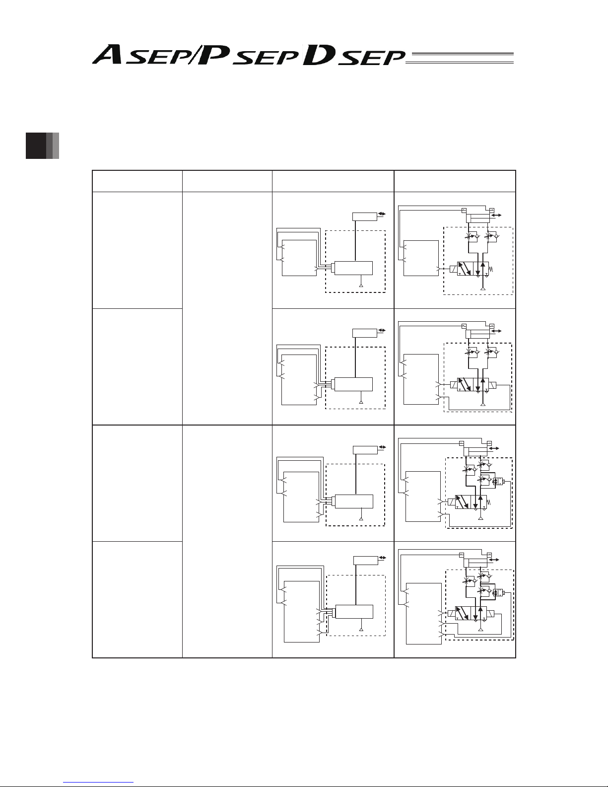
2.2 PIO Pattern Selection and PIO Signal
(1) Operation Pattern
The 6 operation patterns (For PIO Pattern). Each of these 6 patterns is described as in the table. Also,
the corresponding air cylinder circuit is described for reference.
Operation Pattern Contents
Example for Electric Cylinder
Connection
Example for Air Cylinder
Connection (Reference)
PIO Pattern 0
Single Solenoid System
(Standard Point-to-Point
Movement)
The actuator pointto-point movement is
available using the same
control function as for
the air cylinder.
The target position
setting (forward position
and backward position)
is available.
Speed and acceleration
settings in the actuator
movement are available.
The pressing operation
is available.
PLC
+24V
ASEP,
PSEP,
DSEP
Electric Cylinder
Dedicated
Cable
Movement Signal
(ST0)
Backward
Position Detection
(LS0)
Forward
Position Detection
(LS1)
R2 R1
B A
Spring
Solenoid
Air Cylinder
PLC
Movement Signal
(ST0)
P(Air)
Forward
Position Detection
(LS1)
Backward
Position Detection
(LS0)
PIO Pattern 0
Double Solenoid System
(Standard Point-to-Point
Movement)
+24V
ASEP,
PSEP,
DSEP
Electric Cylinder
Dedicated
Cable
PLC
Backward Position
Movement Signal
(ST0)
Forward Position
Movement Signal
(ST1)
Backward
Position Detection
(LS0)
Forward
Position Detection
(LS1)
R2 R1
B A
Solenoid
Solenoid
Air Cylinder
PLC
P(Air)
Movement Signal
(ST0)
Forward Position
Movement Signal
(ST1)
Backward
Position Detection
(LS0)
Forward
Position Detection
(LS1)
PIO Pattern 1
Single Solenoid System
(
Point-to-Point Movement
)
(
Movement Speed Setting
)
The actuator pointto-point movement is
available using the same
control function as for
the air cylinder.
The speed change in the
movement operation is
available.
The target position
setting (forward position
and backward position)
is available.
Speed and acceleration
settings in the actuator
movement are available.
The pressing operation
is available.
+24V
ASEP,
PSEP,
DSEP
Electric Cylinder
Dedicated
Cable
PLC
Movement Signal
(ST0)
Movement Speed
Change Signal
(SPDC)
Backward
Position Detection
(LS0)
Forward
Position Detection
(LS1)
Spring
R2
R1
B A
Solenoid
Air Cylinder
PLC
P(Air)
Movement Signal
(ST0)
Movement Speed
Change Signal
(SPDC)
Backward
Position Detection
(LS0)
Forward
Position Detection
(LS1)
PIO Pattern 1
Double Solenoid System
(
Point-to-Point Movement
)
(
Movement Speed Setting
)
+24V
ASEP,
PSEP,
DSEP
Electric Cylinder
Dedicated
Cable
PLC
Backward Position
Movement Signal
(ST0)
Forward Position
Movement Signal
(ST1)
Movement Speed
Change Signal
(SPDC)
Backward
Position Detection
(LS0)
Forward
Position Detection
(LS1)
R2
R1
B A
Solenoid
Solenoid
Air Cylinder
PLC
P(Air)
Backward Position
Movement Signal
(ST0)
Forward Position
Movement Signal
(ST1)
Movement Speed
Change Signal
(SPDC)
Backward
Position Detection
(LS0)
Forward
Position Detection
(LS1)
Page 37

31
/
2. Wiring
Operation Pattern Contents
Example for Electric Cylinder
Connection
Example for Air Cylinder
Connection (Reference)
Single Solenoid System
(
Point-to-Point Movement
)
(Target Position Setting
(Position Data) Change)
The actuator pointto-point movement is
available using the same
control function as for
the air cylinder.
The change-over
between the positioning
and pressing operations
during the operation is
available.
The target position
setting (forward position
and backward position)
is available.
Speed and acceleration
settings in the actuator
movement are available.
The pressing operation
is available.
+24V
ASEP,
PSEP,
DSEP
Electric Cylinder
Dedicated
Cable
PLC
Movement Signal
(ST0)
Target Position
Change Signal
(CN1)
Backward
Position Detection
(LS0)
Forward
Position Detection
(LS1)
R2
R1
B A
Air Cylinder
PL C
P(Air)
P(Air)
Movement Signal
(ST0)
Target Position
Change Signal
(CN1)
Backward
Position Detection
(LS0)
Forward
Position Detection
(LS1)
PIO Pattern 2
Double Solenoid System
(
Point-to-Point Movement
)
(Target Position Setting
(Position Data) Change)
+24V
ASEP,
PSEP,
DSEP
Electric Cylinder
Dedicated
Cable
PLC
Backward Position
Movement Signal
(ST0)
Forward Position
Movement Signal
(ST1 )
Target Position
Change Signal
(CN1)
Backward
Position Detection
(LS0)
Forward
Position Detection
(LS1)
R2
R1
B
A
Air Cylinder
PLC
P(Air)
P(Air)
Backward Position
Movement Signal
(ST0)
Forward Position
Movement Signal
(ST1 )
Target Position
Change Signal
(CN1)
Backward
Position Detection
(LS0)
Forward
Position Detection
(LS1)
PIO Pattern 3
(2-Input, 3-Point
Movement)
The actuator 3-Point
Movement is available
using the same control
function as for the air
cylinder.
The target position
setting (forward position,
backward position and
intermediate position) is
available.
Speed and acceleration
settings in the actuator
movement are available.
The pressing operation at
the positions except for
the intermediate position
is abailable.
+24V
ASEP,
PSEP,
DSEP
Electric Cylinder
Dedicated
Cable
PLC
Movement
Signal 1
(ST0)
Movement
Signal 2
(ST1 )
Backward
Position Detection
(LS0)
Forward
Position Detection
(LS1)
Intermediate
Position Detection
(LS2)
Air Cylinder
PLC
P(Air)
P(Air)
P(Air)
Movement
Signal 1
(ST0)
Movement
Signal 2
(ST1 )
Backward
Position Detection
(LS0)
Forward
Position Detection
(LS1)
Intermediate
Position Detection
(LS2)
PIO Pattern 4
(3-Input, 3-Point
Movement)
The actuator 3-Point
Movement is available
using the same control
function as for the air
cylinder.
The target position
setting (forward position,
backward position and
intermediate position) is
available.
Speed and acceleration
settings in the actuator
movement are available.
The pressing operation
at the positions except
for the intermediate
position is abailable.
+24V
ASEP,
PSEP,
DSEP
Dedicated
Cable
PLC
Electric Cylinder
Intermediate Position
Movement Signal
(ST2)
Backward Position
Movement Signal
(ST0)
Forward Position
Movement Signal
(ST1)
Backward
Position Detection
(LS0)
Forward
Position Detection
(LS1)
Intermediate
Position Detection
(LS2)
Air Cylinder
PLC
P(Air)
P(Air)
P(Air)
Intermediate Position
Movement Signal
(ST2)
Backward Position
Movement Signal
(ST0)
Forward Position
Movement Signal
(ST1)
Backward
Position Detection
(LS0)
Forward
Position Detection
(LS1)
Intermediate
Position Detection
(LS2)
Page 38

32
/
2. Wiring
Operation Pattern Contents
Example for Electric Cylinder
Connection
Example for Air Cylinder
Connection (Reference)
PIO Pattern 5
(Continuous
Reciprocating
Operation)
The actuator’s pointto-point reciprocating
operation is performed
between the forward
position and backward
position.
The target position
setting (forward position
and backward position)
is available.
Speed and acceleration
settings in the actuator
movement are available.
The pressing operation
is available.
Note: The air cylinder circuit is described with the symbols for the signals corresponding to those in
ASEP/PSEP/DSEP.
[Refer to the next page for the details of each signal.]
Page 39

33
/
2. Wiring
(2) PIO Pattern and Signal Assignment
Pattern 0 1 2 3 4 5
Point-to-Point
Movement
(Standard)
Point-to-Point
Movement
(Movement
Speed Setting)
Point-to-Point
Movement
(Target Position
Setting Change)
3-Point
Movement
(2-Input)
3-Point
Movement
(3-Input)
Point-to-Point
Reciprocating
Movement
(Continuous
Reciprocating
Operation)
Pin
No.
Cable
Color
Input/
Output
Single
Double
Single
Double
Single
Double
-
Double
-
1 BR COM 24V 24V 24V 24V 24V 24V
2 RD COM 0V 0V 0V 0V 0V 0V
3OR
I
N
0 ST0 ST0 ST0 ST0 ST0 ST0 ST0 ST0 ASTR
4YW 1
*
STP
ST1
(Note 1)
*
STP
ST1
(Note 1)
*
STP
ST1
(Note 1)
ST1
(Note 1)
ST1
(Note 1)
*
STP
5 GN 2 RES SPDC (RES)
(Note 2)
CN1 (RES)
(Note 2)
RES ST2(RES)
(Note 2)
RES
6BL 3 /SON
/SON
/SON
/SON
/SON
/SON
7PL
O
U
T
0 LS0/PE0 LS0/PE0 LS0/PE0 LS0/PE0 LS0/PE0 LS0/PE0
8 GY 1 LS1/PE1 LS1/PE1 LS1/PE1 LS1/PE1 LS1/PE1 LS1/PE1
9 WT 2 HEND/SV HEND/SV HEND/SV LS2/PE2 LS2/PE2 HEND/SV
10 BK 3
*
ALM/SV
*
ALM/SV
*
ALM/SV
*
ALM/SV
*
ALM/SV
*
ALM/SV
(Note 1) : It is invalid before home-return operation.
(Note 2) : The description in the brackets shows the condition before the home return operation.
(Note 3) : *STP and *ALM are the signals that are negative logic.
(Reference) Signal of Active Low
Signal with “*” expresses the signal of active low. A signal of active low is a signal that the input signal
is processed when it is turned off, output signal is ordinary on while the power is on, and turns off when
the signal is output.
Page 40

34
/
2. Wiring
(3) List of PIO Signal Functions
Signal
Type
Symbol Signal Name Function
Power
Input
24V I/O Power Supply
It is the common power source for I/O circuit. The positive () side of 24V
DC is connected.
0V I/O Power Supply
It is the common power source for I/O circuit. The positive () side of 24V
DC is connected.
Input
ST0
• Movement Signal
[Single Solenoid System]
• Backward Position
Movement Signal
[Double Solenoid System]
• Movement Signal 1
[PIO Pattern 3]
The positioning to the corresponding target position is performed, when the
signal leading edge created in the mode change from OFF to ON, or ON
level is detected.
ST1
• Forward Position
Movement Signal
• Movement Signal 2
[PIO Pattern 3]
ST2
Intermediate Position
Movement Signal
*STP Pause Signal
When this signal is turned OFF the deceleration is stopped. When the signal
is turned ON again, the movement is re-started.
RES Reset Signal
When the signal leading edge created in the mode change from OFF to ON,
is detected, the currently issued alarm is reset.
* Depending on the alarm level, alarm reset might not be available.
Refer to the Trouble Shooting for the details.
SON Servo ON Signal
During the time when this signal is turned ON, the servo-motor is in the ON mode.
SPDC
Movement Speed Change
Signal
When the movement speed is changed during the movement, do it with this
signal turned ON.
* This signal is effective when the PIO pattern 1 has been set.
CN1
Target Position Change
Signal
When the conditions for the positioning operation or pressing operation, etc.,
are changed to operate the system, turn ON this signal.
When this signal is turned ON or OFF during the operation, the position data
is changed.
* This signal is effective when the PIO pattern 2 has been set.
ASTR
Continuous Reciprocating
Operation Signal
During the time when this signal is turned ON, the actuator’s continuous
reciprocating operation is performed between the forward position and the
backward position. When this signal is turned OFF during the movement
operation, after the actuator is positioned to the current target, it is stopped.
* This signal is effective when the PIO pattern 5 has been set.
Output
LS0
Backward Position
Detection
The same operation as of the limit switch of the air cylinder is performed.
It is turned ON when the current position is within the positioning width for
each position detection output.
LS1 Forward Position Detection
LS2
Intermediate Position
Detection
PE0
Backward Positioning
Completion
This signal is turned ON when the current position goes within the positioning width, and the positioning to the target position is complete.
It is turned OFF in the Servo-Motor OFF mode or the Emergency Stop
Mode.
PE1
Forward Positioning
Completion
PE2
Intermediate Positioning
Completion
HEND Home Return Completion This signal is turned ON when the home return operation is completed.
SV Servo ON Signal
This signal is turned ON when the servo-motor is turned ON and driving is enabled.
*ALM Alarm Output Signal
This signal is turned ON when the controller is in the normal condition and
turned OFF when the controller is in the alarm condition. In such case,
monitor this signal in the PLC and take an appropriate measure.
Note For the PLC Input signal, keep it ON for at least 7ms or more.
Page 41

35
/
2. Wiring
2.3 Circuit Diagram (Example)
[1] Power/Emergency Stop Circuit
CR
CR
CR
Brake Power Sopply
Motor Power Sopply
ASEP/PSEP/DSEP
Emergency
Stop Release
Switch
24V 0V
EMG (Emergency Stop Input)
BK
(BK connection not required for DSEP)
MP
24V 0V
Emergency
Stop Switch
for Device
(System)
Power Supply Connector
Turn ON to
Release Brake
[2] Pattern 0 : Point-to-Point Movement (Standard)
1) Single Solenoid System
ASEP/PSEP/DSEP
PIO Connector
Movement Signal
Pause Signal
(Reset Signal)
Servo ON Signal
0V (NPN Type)
24V DC (PNP Type)
BR
OR
YW
GN
BL
1
3
4
5
6
RD
PL
GY
WT
BK
2
7
8
9
10
P24
ST0
*STP
RES
–/SON
0V
LS0/PE0
LS1/PE1
HEND/SV
*ALM/SV
24V DC (NPN Type)
0V (PNP Type)
Backward Position Detection/
Backward Positioning Completion
Forward Position Detection/
Forward Positioning Completion
Home Return Completion/
Servo ON Signal
Alarm Output Signal/
Servo ON Signal
Load
24V DC
Supply
0V Supply
2) Double Solenoid System
ASEP/PSEP/DSEP
PIO Connector
Backward Position
Movement Signal
Forward Position
Movement Signal
(Reset Signal)
Servo ON Signal
0V (NPN Type)
24V DC (PNP Type)
BR
OR
YW
GN
BL
1
3
4
5
6
RD
PL
GY
WT
BK
2
7
8
9
10
P24
ST0
*STP
RES
–/SON
0V
LS0/PE0
LS1/PE1
HEND/SV
*ALM/SV
24V DC (NPN Type)
0V (PNP Type)
Backward Position Detection/
Backward Positioning Completion
Forward Position Detection/
Forward Positioning Completion
Home Return Completion/
Servo ON Signal
Alarm Output Signal/
Servo ON Signal
Load
24V DC
Supply
0V Supply
Page 42

36
/
2. Wiring
[3] Pattern 1 : Point-to-Point Movement (Movement Speed Change)
1) Single Solenoid System
ASEP/PSEP/DSEP
PIO Connector
Movement Signal
Pause Signal
Movement Speed Change Signal
(Reset Signal)
Servo ON Signal
0V (NPN Type)
24V DC (PNP Type)
BR
OR
YW
GN
BL
1
3
4
5
6
RD
PL
GY
WT
BK
2
7
8
9
10
P24
ST0
*STP
SPDC (RES)
–/SON
0V
LS0/PE0
LS1/PE1
HEND/SV
*ALM/SV
24V DC (NPN Type)
0V (PNP Type)
Backward Position Detection/
Backward Positioning Completion
Forward Position Detection/
Forward Positioning Completion
Home Return Completion/
Servo ON Signal
Alarm Output Signal/
Servo ON Signal
Load
24V DC
Supply
0V Supply
2) Double Solenoid System
ASEP/PSEP/DSEP
PIO Connector
Backward Position
Movement Signal
Forward Position
Movement Signal
Movement Speed Change Signal
(Reset Signal)
Servo ON Signal
0V (NPN Type)
24V DC (PNP Type)
BR
OR
YW
GN
BL
1
3
4
5
6
RD
PL
GY
WT
BK
2
7
8
9
10
P24
ST0
ST1 (–)
SPDC (RES)
–/SON
0V
LS0/PE0
LS1/PE1
HEND/SV
*ALM/SV
24V DC (NPN Type)
0V (PNP Type)
Backward Position Detection/
Backward Positioning Completion
Forward Position Detection/
Forward Positioning Completion
Home Return Completion/
Servo ON Signal
Alarm Output Signal/
Servo ON Signal
Load
24V DC
Supply
0V Supply
Page 43

37
/
2. Wiring
[4] Pattern 2 : Point-to-Point Movement (Target Position Change)
1) Single Solenoid System
ASEP/PSEP/DSEP
PIO Connector
Movement Signal
Pause Signal
Target Position Change Signal
(Reset Signal)
Servo ON Signal
0V (NPN Type)
24V DC (PNP Type)
BR
OR
YW
GN
BL
1
3
4
5
6
RD
PL
GY
WT
BK
2
7
8
9
10
P24
ST0
*STP
CN1 (RES)
–/SON
0V
LS0/PE0
LS1/PE1
HEND/SV
*ALM/SV
24V DC (NPN Type)
0V (PNP Type)
Backward Position Detection/
Backward Positioning Completion
Forward Position Detection/
Forward Positioning Completion
Home Return Completion/
Servo ON Signal
Alarm Output Signal/
Servo ON Signal
Load
24V DC
Supply
0V Supply
2) Double Solenoid System
ASEP/PSEP/DSEP
PIO Connector
Backward Position
Movement Signal
Forward Position
Movement Signal
Target Position Change Signal
(Reset Signal)
Servo ON Signal
0V (NPN Type)
24V DC (PNP Type)
BR
OR
YW
GN
BL
1
3
4
5
6
RD
PL
GY
WT
BK
2
7
8
9
10
P24
ST0
ST1 (–)
CN1 (RES)
–/SON
0V
LS0/PE0
LS1/PE1
HEND/SV
*ALM/SV
24V DC (NPN Type)
0V (PNP Type)
Backward Position Detection/
Backward Positioning Completion
Forward Position Detection/
Forward Positioning Completion
Home Return Completion/
Servo ON Signal
Alarm Output Signal/
Servo ON Signal
Load
24V DC
Supply
0V Supply
Page 44

38
/
2. Wiring
[5] Pattern 3 : 3-Point Movement (2-Input)
ASEP/PSEP/DSEP
PIO Connector
Movement Signal 1
Movement Signal 2
(Reset Signal)
Servo ON Signal
0V (NPN Type)
24V DC (PNP Type)
BR
OR
YW
GN
BL
1
3
4
5
6
RD
PL
GY
WT
BK
2
7
8
9
10
P24
ST0
ST1
RES
–/SON
0V
LS0/PE0
LS1/PE1
LS2/PE2
*ALM/SV
24V DC (NPN Type)
0V (PNP Type)
Backward Position Detection/
Backward Positioning Completion
Forward Position Detection/
Forward Positioning Completion
Intermediate Position Detection/
Intermediate Positioning Completion
Alarm Output Signal/
Servo ON Signal
Load
24V DC
Supply
0V Supply
[6] Pattern 4 : 3-Point Movement (3-Input)
ASEP/PSEP/DSEP
PIO Connector
Backward Position
Movement Signal
Forward Position
Movement Signal
Intermediate Position Movement Signal
(Reset Signal)
Servo ON Signal
0V (NPN Type)
24V DC (PNP Type)
BR
OR
YW
GN
BL
1
3
4
5
6
RD
PL
GY
WT
BK
2
7
8
9
10
P24
ST0
ST1 (–)
ST2 (RES)
–/SON
0V
LS0/PE0
LS1/PE1
LS2/PE2
*ALM/SV
24V DC (NPN Type)
0V (PNP Type)
Backward Position Detection/
Backward Positioning Completion
Forward Position Detection/
Forward Positioning Completion
Intermediate Position Detection/
Intermediate Positioning Completion
Alarm Output Signal/
Servo ON Signal
Load
24V DC
Supply
0V Supply
[7] Pattern 5 : Point-to-Point Reciprocating Movement (Continuous Reciprocating Operation)
ASEP/PSEP/DSEP
PIO Connector
Continuous Reciprocating
Operation Signal
Pause Signal
(Reset Signal)
Servo ON Signal
0V (NPN Type)
24V DC (PNP Type)
BR
OR
YW
GN
BL
1
3
4
5
6
RD
PL
GY
WT
BK
2
7
8
9
10
P24
ST0
ST1
RES
–/SON
0V
LS0/PE0
LS1/PE1
HEND/SV
*ALM/SV
24V DC (NPN Type)
0V (PNP Type)
Backward Position Detection/
Backward Positioning Completion
Forward Position Detection/
Forward Positioning Completion
Home Return Completion/
Servo ON Signal
Alarm Output Signal/
Servo ON Signal
Load
24V DC
Supply
0V Supply
Page 45

39
/
2. Wiring
[8] Input Emergency Stop to Multiple Controllers
+24V
0V
External EMG
Reset Switch
External
EMG
Switch
Touch Panel
Teaching
SIO Converter
EMGB
EMGA
EMG2
EMG1
ASEP/PSEP/DSEP
EMG (Emergency Stop Input)
EMG (Emergency Stop Input)
EMG (Emergency Stop Input)
CR
CR
PORT
Switch
ASEP/PSEP/DSEP
ASEP/PSEP/DSEP
Page 46

40
/
2. Wiring
[9] Motor • Encoder Connector
ASEP/PSEP/DSEP
MOT PG
(Motor · Encoder
Cable Connector)
Motor · Encoder
Connector Integrated Cable
(Note)
(Note) Motor · Encoder Connector Integrated Cable is an accessory of the actuator.
□□□ : Cable Length Example) 030 3m
CB-ACS-MPA (for RCA2, RCL)
CB-APSEP-MPA (for RCA2, RCL)
CB-CA-MPA (for RCD)
CB-ASEP-MPA (for RCA)
CB-PCS-MPA (for RCP3)
CB-APSEP-MPA (for RCP3)
CB-RPSEP-MPA (for RCP2 Small Rotary)
CB-PSEP-MPA (for RCP2 (except for Small Rotary))
Note: Connection to the Existing ROBO Cylinder
For the connection to the existing ROBO Cylinder Series actuators, please purchase and prepare a
connection cable separately from the following table.
ROBO Cylinder Series
that you may already have
Connection Cable (to be purchased separately)
□□□ shows the cable length. (Example : 0505m)
Applicable
Controller
RCP2(except for Small Rotary Type) CB-PSEP-MPA□□□ PSEP
• Small Rotary Type
RCP2-RTBS RCP2-RTBSL
RCP2-RTCS RCP2-RTCSL
CB-RPSEP-MPA□□□
RCP3 CB-APSEP-MPA□□□
Extension Cable : CB-APSEP-MPA□□□JY(JYP)
ASEP, PSEP
RCA2, RCL
RCA CB-ASEP-MPA□□□ ASEP
[10] Connection to Absolute Battery Unit (Limited only to ASEP/PSEP applicable for Simple Absolute
Type)
ASEP/PSEP
Absolute Battery Unit (SEP-ABUM)
Connection Cable
between Controller and
Absolute Battery
*1
BATT
(Battery Connector)
*1 Connection Cable between Controller and Absolute Battery
CB-APSEP-ABM005 • • • Applicable Controller : ASEP-C-□-□-□-0-ABUM□
PSEP-C-□-□-□-0-ABUM□
CB-APSEP-AB005 • • • Applicable Controller : ASEP-C-□-□-□-0-ABU□
(Existing models: Not complied with UL) PSEP-C-□-□-□-0-ABU□
Page 47

41
/
2. Wiring
2.4 Wiring Method
2.4.1 Wiring Layout of Power Supply Connector
The wires of the power supply and the emergency stop circuit are to be connected to the enclosed
connector (plug).
trip the sheath of the applicable wires for 7mm and insert them to the connector. Push a protrusion
beside the cable inlet with a small slotted screwdriver to open the inlet. After inserting a cable, remove
the screwdriver from the protrusion to fi x the cable.
24V DC
Power
Supply
+
24V
0V
Brake Release
Switch
(Turn ON to
Release Brake)
1 Pin
(BR)
2 Pin
(RD)
(MC1.5/5-ST-3.5)
Accessory I/O
Flat Cable
Emergency
Stop Circuit
[Refer to 2.3]
Accessory Power
Supply Connector
Class D Grounding
● Power Supply Connector
Connector Name Cable Side MC1.5/5-ST-3.5 Standard Accessory
Controller Side MC1.5/5-G3.5
Pin No. Signal Name Contents Applicable Wire Diameter
1 EMGIN
Input of Emergency Stop
Status Signal
(Note 1)
KIV0.5mm2 (AWG20)
20V
Power Supply Input (24V DC ±10%) KIV1.25mm
2
(AWG16)
3 24V
4 MP Motor Driving Power Supply Line KIV1.25mm
2
(AWG16)
5BK
Brake Forced Release Power Supply
Input
(Note 2)
(24V DC ±10% 150mA)
KIV0.5mm2 (AWG20)
(Note 1) The emergency stop status signal input determines as the system is in normal condition when 24V
DC is input and in emergency stop when 0V is input. Once in emergency stop, the actuator stops its
operation and turns the servo off.
Construct the emergency stop circuit suits for the safety category considering the entire system.
(Note 2) The brake is compulsorily released when +24V is supplied. Make the 0V in common with the 0V of the
power input. Do not apply on DSEP.
Page 48

42
/
2. Wiring
2.4.2 Wiring Layout of FG Terminal Block
FG is to be connected to a screwless terminal block.
Strip the sheath of the applicable wires for 11mm and insert them to the connector. Push a protrusion
beside the cable inlet with a small slotted screwdriver to open the inlet. After inserting a cable, remove
the screwdriver from the protrusion to fi x the cable.
● FG Terminal Block
Terminal Block Name FG
Controller Side ML-800-S1H1P
Pin No. Signal Name Contents Applicable Cable
1 FG Ground Cable Connection KIV1.25mm
2
(AWG16)
Page 49

43
/
2. Wiring
2.4.3 Connection to Actuator
Connect the cables to the motor • encoder connectors.
Note:
For Simple Absolute applicable type, remove the absolute battery connector from the controller
before connecting the cable.
● Motor • Encoder Connector Specifi cations
Connector Name MOT
PG
Cable Side PADP-24V-1-S
Controller Side S24B-PADSS-1
Pin
No.
Signal Name
Contents
Applicable
Wire
Diameter
ASEP PSEP DSEP
1UAU
Motor Driving Line
Cable
dedicated
for IAI
products
2 V VMM V
3-B4 - VMM 5W/A W
6-/B 7BKLS
LS* : Home Position Confi rmation Sensor
BK* : Brake Power Supply
8BKLS
-
9LSBK
LS
10 LS
BK
LS
11 ENA - ENA
EN* : Encoder Signal
HS* : Hall IC Signal
12 /ENA - /ENA
13 ENB ENA ENB
14 /ENB /ENA /ENB
15 ENZ ENB HS1
16 /ENZ /ENB HS2
17 5V 5V 5V Encoder Power Supply
18 /PS VPS - Encoder Line Driver Enable Output
19 GND GND GND Ground
20 LSGND LSGND HS3
LSGND : Ground for Limit Switch
HS3 : Hall IC Signal
21 NC NC NC Disconnected
22 NC NC NC Disconnected
23 NC NC NC Disconnected
24 FG FG FG Ground
Page 50

44
/
2. Wiring
2.4.4 Connection of PIO
Conduct the connection of I/O to the controller is to be carried out using the dedicated I/O cable. The
cable length is shown in the model code of the controller. Please check the controller model code.
There are 2m for standard, 3m and 5m as an option. 10m is also applicable at maximum if purchased
separately. [Refer to “1.1.5. How to read the model]
Also, the end of the cable harness to be connected to the host controller (PLC, etc.) is just cut and no
treatment is conducted so the wiring layout can be performed freely.
Model : CB-APSEP-PIO□□□···For ASEP-C, PSEP-C
(□□□ shows the cable length L Example.0202m)
● PIO Connector
Applied Connector 55959-1030 Manufactured by MOLEX
Connector Name I/O PIO Connector
Connection Cable
Dedicated Cable [refer to (3) in this
section.]
Enclosed in this controller
L
10
2 1
9
Model : CB-APSEPW-PIO□□□···For ASEP-CW, PSEP-CW
(□□□ shows the cable length L Example.0202m)
L
10
21
9
Connector 51353-1000 (Manufactured by MOLEX)
No.
Color
Signal Name
CB-APSEP-PIO□□□ CB-APSEPW-PIO□□□
1 BR BR 24V
2 RD BR, WT 0V
3 OR RD IN0
4 YW RD, WT IN1
5 GN YW IN2
6 BL YW, WT IN3
7 PL GN OUT0
8 GY GN, WT OUT1
9 WT BK OUT2
10 BK BK, WT OUT3
Page 51

45
/
2. Wiring
2.4.5 SIO Connector Connection
SIO connectors can be used not only for the connection of teaching tool, but also for the
connection of the host controller (PLC, touch panel and PC).
For the operation, refer to the instruction manual of each module.
[Refer to Instruction manuals related to this product, which are contained in CD/DVD.]
PC
Touch Panel
Teaching
Note:
If the teaching pendant is removed with the power supply being on, the condition will become the transient
emergency stop and the operated actuator will stop.
Do not disconnect the teaching pendant during the operation.
Page 52

46
/
2. Wiring
2.4.6 Battery Connector Connection (For Simple Absolute Type)
The absolute battery unit is to be connected to the battery connector.
Connect the dedicated cable enclosed with the absolute battery unit.
Connection Cable between Controller and Absolute Battery : CB-APSEP-AB005
Applicable Controller ASEP- □ - □ - □ -0-ABUM
PSEP- □ - □ - □ -0-ABUM
(Absolute Battery Unit)
Connection Cable [Refer to 1.10.9]
(Absolute Battery Unit
Accessories
)
● Battery Connector
Applicable Connector 53015-0310 (Model: ABUM, ABUNM) Manufactured by Molex
S3B-PH-K-S (LF) (SN)
(Model: ABU, ABUN)
Manufactured by JST
Connector Name BATT Battery Connector
Connection Cable Dedicated Cable Enclosed in the absolute battery unit
Pin No. Signal Name Contents
1 BT Negative Side of Battery Power Supply
2 GND Positive Side of Battery Power Supply
3 BTMP For Battery Temperature Detection
Page 53

47
/
2. Wiring
Battery
Name NiMH battery (FDK Corporation)
Model AB-7
Rated 3.6V 3300mAh
Nominal 3.6V3700mAh
Battery Life (reference) Approximately 3 years (It may vary depending on the usage condition.)
Charging Time Approximately 72 hours
Note: About Battery Charge and Discharge
When using for the fi rst time or the fi rst time after the battery is replaced, do not charge the battery
for more than 72 hours in a row.
The battery can be charged when 24V is supplied to the controller.
The encoder data will be able to be retained for the duration
(Note)
stated below as per hour of battery
charge.
The data will be lost if the controller is turned OFF for longer than the data retained duration. Start
charging the battery as early as possible.
The battery has a limited product life and the data retained duration will gradually decrease. If a
sudden huge decrease started to occur to the retained duration, replace the battery.
(Note) Data Retained Duration per Hour Battery Charge
* The values stated below are the reference values of when the battery is new.
Setting in user parameter No. 19 0 1 2 3
Data Retained Duration
(reference)
6.6H 5.0H 3.3H 1.6H
[Refer to section 3.4 for the user parameter No.19.]
Page 54

48
/
3. Operation
3. Operation
3.1 Setting
3.1.1 Initial Setting
Conduct the following initial settings on the PC software or Touch Panel Teaching.
Refer to the Instruction Manual for the PC software or Touch Panel Teaching for the details of the
settings.
• Initial Setting Items
* There may be some items that are not displayed depending on the selected operation patterns.
No. Setting Items
Setting Range
(Set in delivery)
Contents
PIO Pattern
012345
1 PIO Pattern
(Operation
Pattern)
0 to 5 (0) Set it to the pattern to be used.
○○○○○○
2 Operation
Mode
(Solenoid
System)
Single/Double
(Double)
It is selectable only when the PIO pattern is set to “0”,
“1” or “2”. Select “Single” (Single Solenoid System) or
“Double” (Double Solenoid System).
○○○
3 Stop Signal Enable/Disable
(Disable)
It is selectable only when “Single” is selected in “2.
Operation Mode (Solenoid System)”.
When the PAUSE signal (*STP) is used, select
“Enable”.
○○○ ○
4 Input Signal
System
(Solenoid
Type)
Continuous
Operation Type
/Momentary
Operation Type
(Continuous
Operation Type)
It is selectable only when “Double” is selected in “2.
Operation Mode (Solenoid System)”.
For the signal sent from PLC to ASEP, PSEP or
DSEP, select “Continuous Operation” (level signal) or
“Momentary Operation” (edge signal).
○○○ ○
5 Intermediate
Stop System
Both Solenoids
ON
/Both Solenoids
OFF
(Both Solenoids
OFF)
It is selectable only when the PIO pattern is set to “3”.
In the case the same use procedure as for 5-port
3-position electromagnetic valve is applied, select
“Both Solenoid OFF”.
In the case that the same use procedure as the
time when two units of the 3-port single solenoid
electromagnetic valve, are used, select “Both
Solenoid ON”.
○
6 Servo-motor
Control
Enable/Disable
(Disable)
When “Disable” is selected, the servo-motor is
automatically turned ON after the power input.
When “Enable” is selected, the servo-motor is turned
ON by means of turning ON the SON signal on
INPUT IN3.
○○○○○○
7 Home
Position
Operation
(Home
Return
Operation
Procedure)
AUTO/MANU
(MANU)
If AUTO is selected, the home-return operation is
started automatically when the servo is turned for the
fi rst time after the power is supplied. When “MANU” is
selected, the home return operation is performed with
the fi rst ST0 input.
○○○○○○
Page 55

49
/
3. Operation
No. Setting Items
Setting Range
(Set in delivery)
Contents
PIO Pattern
012345
8 Output Signal
Type
Limit Switch
/Positioning
(Limit Switch)
The actuator is moved and the signal output system
after the positioning completion is selected.
• Limit Switch : When the actuator reaches the target
position, it is turned ON. (Even when
the servo-motor is turned ON and
if the current position is within the
positioning width, the ON mode is
continued.
In the Intermediate Position, when the
actuator pass through the point, the
position is within the range (within the
positioning width), it is turned ON.
Intermediate Position is reached. :LS2 ON
Forward Position is reached. :LS1 ON
Backward Position is reached. :LS0 ON
• Positioning : When the actuator reaches the target
position, it is turned ON. (When the
servo-motor is turned OFF, this signal
is turned OFF. When the servo-motor
is turned ON again and the current
position is within the positioning width,
it is turned ON.
Intermediate Position is reached. :PE2 ON
Forward Position is reached. :PE1 ON
Backward Position is reached. :PE0 ON
○○○○○○
9 Output Signal
Selection
0 to 2
(0)
When “Enable” is selected for “6. Servo-motor
Control”, select whether or not the servo-motor ON
signal STATUS is output.
Select the following combination parameter “0”, “1”
or “2”, when the PIO pattern “0”, “1”, “2” or “5” is
selected.
0 : OUT2 HEND
OUT3 *ALM
(
There is no “Servo-motor ON” signal output
)
1 : OUT2 SV, OUT3 *ALM
2 : OUT2 HEND, OUT3 SV
Select the following combination parameter “0” or “1”,
when the PIO pattern “3” or “4” is selected.
0 : OUT3 *ALM
(
There is no “Servo-motor ON” signal output
)
1 : OUT3 SV
* When “Disable” is selected for “6. Servo-motor
Control”, this signal is allocated to “0” (There is no
“Servo-motor ON” signal output).
○○○○○○
Page 56

50
/
3. Operation
3.1.2 Position Data Setting
Set the following items in the position data editing window of the PC software menu or by selecting
“Position Setting” in the Touch Panel Teaching menu. [Refer to the PC Software or Touch Panel
Teaching Instruction Manual for the details]
Backward
Position
Intermediate
Position
Forward
Position
Motor
A
ctuator
Position Data
Position Data 1) Position 2) Velocity 3)
Acceleration
4)
Deceleration
5) Pressing
Force
6) Pressing
Band
7)
Energy-Saving
Function
Forward Position 200.00 50.00 0.1 0.1 70 1.00 Effective
Backward Position 0.00 50.00 0.1 0.1 0 0 Effective
Intermediate
Position
100.00 50.00 0.1 0.1 0 0 Effective
1) Position … Set the position where the actuator is moved.
Setting Range : 0 to Actuator Stroke Range (Unit 0.01mm)
Operation Pattern Name
: PIO Pattern No.
Displacement
Set Position
Forward
Position
Backward
Position
Intermediate
Position
Standard Point-to-Point Movement :0 Point-to-Point Movement ○○
Movement Speed Setting :1 Point-to-Point Movement ○○
Target Position Setting Change :2 Point-to-Point Movement ○○
2-Input, 3-Point Movement :3 3-Point Movement ○○○
3-Input, 4-Point Movement :4 3-Point Movement ○○○
Continuous Reciprocating Operation :5 Point-to-Point Movement ○○
2) Velocity … Set the actuator speed.
[Refer to Appendix in this manual or the Instruction Manual for the actuator.]
Setting Range : Actuator’s min. speed to Actuator’s max. speed
(Unit: 0.01mm/sec)
3) Acceleration … Set the actuator acceleration.
[Refer to Appendix in this manual or the Instruction Manual for the actuator.]
Setting Range : 0.01 to Actuator’s rated Value Range (Unit: 0.1G)
4) Deceleration … Set the actuator deceleration.
[Refer to Appendix in this manual or the Instruction Manual for the actuator.]
Setting Range : 0.01 to Actuator’s rated Value Range (Unit: 0.1G)
Page 57

51
/
3. Operation
Note:
Regarding to Acceleration/Deceleration Speed Setting
(1) Do not have the setting to exceed the rated acceleration/deceleration speed that is specifi ed
in the catalog or this Instruction Manual. The setting that exceeds the rated acceleration/
deceleration speed may shorten the actuator life remarkably.
(2) Consider to lower the acceleration/deceleration speed when a shock or vibration is applied to
the actuator or work. In such a case, keeping the use under such a condition may shorten the
actuator life remarkably.
5) Pressing Force … Set the pressing torque (current limit value) in % for the pressing operation.
Having a bigger power limit value gives bigger pressing force.
It is set to the positioning operation when setting to “0”.
[Refer to Appendix in this manual or the Instruction Manual for the actuator.]
Setting Range : 0 (pressing operation is disabled), 20 to 70%
(Note 1)
(Unit: 1%)
It differs depending on the actuator.
[Refer to Appendix in this manual or the Instruction Manual for the actuator.]
6) Pressing Width … Set the position for starting the pressing operation.
The position moved as much distance as the pressing width to the center
from the movement target position (forward position or backward position), is
regarded as the starting position, the pressing operation is started.
Pressing Width
A
ctuator Operation
(2) Setting by Speed
(1) Setting by Position
Set the pressing speed in Parameter No. 7
Pressing operation completes when the
pressing force reaches the specified value within
the pressing band range.
Velocity
Time
Pressing Width
Pressing Complete
(Positioning complete
signal output)
Pressing
Start Position
[Pressing towards Forward Position or Intermediate Position]
Backward
Position
Forward Position
(Intermediate Position)
Page 58

52
/
3. Operation
[Pressing towards Backward Position or Intermediate Position Pulling Action]
Velocity
Time
Pressing Complete
(Positioning complete
signal output)
Pressing Width
Pressing
Start Position
Backward
Position
(Intermediate
Position)
Forward
Position
7) Energy-Saving Function … When it is set to “Enable”, the servo-motor is turned OFF
automatically after the positioning is completed and the specifi ed time
period passes.
(Because the holding current does not pass in the stop mode, the
power consumption can be saved).
The servo-motor is turned ON with the next movement command, and
the actuator movement is started.
The movement speed is to be changed for the Operation Pattern (PIO Pattern) No.1, in addition to
position data, the position where the speed is changed and the velocity parameters are set.
Position Data 8) Changed Position 9) Changed Speed
Forward Position 60.00 30.00
Backward Position 40.00 30.00
8) Changed Position … The position where the velocity is changed in the course of moving to the
forward position or backward position, is set.
9) Changed Speed … The changed speed is set.
Page 59

53
/
3. Operation
When the position data is to be changed for the Operation Pattern (PIO Pattern) No. 2, in addition
to the position data items for the forward position and backward position, the position data items for
the changed forward position and changed backward position, are set.
In the case that the CN1 is turned OFF, the position data for the Forward Position turns to be the
data in 1 Forward Position.
In the case of “ON”, the position data for the forward position are the data specifi ed in “ 3 Forward
Position”.
In the case that the CN1 is turned OFF, the position data for the forward position turns to be the
data in 0 Backward Position.
In the case of “ON”, the position data for the forward position are the data specifi ed in “
2
Backward Position”.
Position Data Position Velocity
Acceleration Deceleration
Pressing
Force
Pressing
Width
Energy-
Saving
Function
0
Backward Position
0.00 50.00 0.1 0.1 0 0 Effective
1
Forward Position 200.00 50.00 0.1 0.1 70 1.00 Effective
2
Backward Position
10.00 50.00 0.1 0.1 0 0 Effective
3
Forward Position 100.00 50.00 0.1 0.1 60 1.00 Effective
Page 60

54
/
3. Operation
3.1.3 Absolute Reset
(This function is effective only when the controller and actuator are the
absolute type).
When the power to the machine is turned ON for the fi rst time, perform the Absolute Reset.
Procedure : After the power is turned ON, an absolute encoder error detection error occurs. Turn ON
the RES signal (IN2), reset the alarm on the alarm window displayed on the PC software,
or touch “RES” on the Alarm window in the Touch Panel Teaching mode to remove the
error. Then, perform the home return operation (In the case that the Absolute Reset has
been performed, the home return window is not displayed).
Page 61

55
/
3. Operation
3.2 Power-up and PIO Control
3.2.1 Control of Input Signal
The input signal of this controller has the input time constant of 7msec considering the
prevention of wrong operation by chattering and noise.
Therefore, ensure the continuous signal for more than 7msec for each input signal. The signal
cannot be identifi ed if it is less than 7msec.
Input Signal
Input Signal
7msec
Identify
Not Identify
Page 62

56
/
3. Operation
3.2.2 Power Input
1) Release the emergency stop status or enable the motor driving power supply.
2) Supply 24V DC for the I/O.
3) Supply 24V DC for the controller.
4) Input the Servo-motor ON signal from the PLC side
(*3)
.
5) Input the Backward Position movement command and signals at fi rst from the PLC side.
[Refer to 3.2.3 Home-return]
Note 1
. When the home return operation is set to “MANU” in the initial setting and the fi rst ST0 is turned ON, the
actuator is returned to the home position and the operation is started.
When it is set to “AUTO”, the actuator is returned to the home position automatically after the servo-motor
ON is input.
The above are effective only when the actuator is incremental type (for the absolute type, the home return
operation is not required).
Note
2. The Servo-motor ON signal is input for the fi rst time after the power input, input the movement command
after the delay time of 1.6sec or more.
In the second time or later, make the delay time of 60ms or more.
Note
3. When the Servo-motor Control is set to “Enable” in the initial setting, the servo-motor is turned ON by
means of inputting the SON signal.
When it is set to “Disable” the servo-motor is turned ON automatically.
Warning: For ASEP and PSEP
The magnetic pole phase detection may not be performed normally if the servo is turned on near
the mechanical end, and may cause such problems like an abnormal operation, magnetic pole not
being defi ned or electromagnetic detection error.
Put it away from the mechanical end when turning the servo on.
Safety Circuit Status
I/O Power 24V DC Supply
Controller Power 24V DC Supply
Servo-on Input
Note 3
(SON)
LED for STATUS Indication
(Backward Position) Movement Signal (1,2) Input
(ST0)
Home Return Completion Output
(HEND)
Backward Position Detection Output
(LS0)
Backward Positioning Completion Output
(PE0)
Actuator Operation
Mechanical
end
Home
Position
6ms or less
1.6sec or less
Note 2
Note 1
Home return
Forward Position
(Single Solenoid System)
Backward Position
(Double Solenoid System)
Page 63

57
/
3. Operation
3.2.3 Home-return
Home-return operation is performed when turning the Movement Signal 1 (ST0) on if the home return
has not yet done since the power is turned on.
1) If the operation pattern is “Point-to-Point Movement (Single Solenoid)”
If the home return is not conducted on the operation panel yet, the fi rst Movement Signal (ST0)
will bring the actuator to the home position. After home return operation, it moves to the forward
position and stops (for positioning).
2) If the operation pattern is “Point-to-Point Movement (Double Solenoid) and 3-Point Movement”
After returning to home position, the actuator stops at the backward position (for positioning).
(Home Return Completion)
Movement signal to the forward position (ST1) is invalid till the home-return operation is complete.
Forward Position Detection Output (LS0)
Movement Signal (ST0)
Home Return Completion (HEND)
Actuator Operation
Reverse at
Mechanical End
Home
Position
Forward
Position
Backward Position Detection Output (LS0)
Movement Signal (ST0)
Actuator Operation
Home
Position
Backward
Position
Reverse at
Mechanical End
Page 64

58
/
3. Operation
3.3 Timing Chart
[1] Point-to-Point Movement (For Single Solenoid System) ••• PIO Pattern 0 to 2
When the ST0 is turned “ON”, the positioning to the backward position is performed and when the
ST0 is turned “OFF”, the positioning to the forward position is performed.
[2] Point-to-Point Movement (For Double Solenoid System) ••• PIO Pattern 0 to 2
With the combination of ST0 and ST1, the actuator is moved to the target position.
* The movement command is to be issued, make sure to turn OFF both ST0 and ST1 and issue the
movement command to the target position.
If it is set to the continuous operation t ype in the initial setting, and both ST0 and ST1 are turned off during
a movement, the actuator decelerates and stops on the spot.
If both ST0 and ST1 are turned on during a movement, the actuator operates following the signal that was
previously on.
Movement Signal (ST0)
Backward Position Detection Output (LS0)
Forward Position Detection Output (LS1)
Backward Positioning Completion Output
(PE0)
Forward Positioning Completion Output
(PE0)
Actuator Operation
**
Backward Position Movement Signal (ST0)
Positioning Band
(Parameter No. 1)
Positioning Band
(Parameter No. 1)
Forward
Position
Backward
Position
Backward
Position
Forward Position Movement Signal (ST1)
Backward Position Detection Output (LS0)
Forward Position Detection Output (LS1)
Backward Positioning Completion Output (PE0)
Forward Positioning Completion Output (PE1)
Actuator Operation
Positioning Band
(Parameter No. 1)
Positioning Band
Positioning Band
(Parameter No. 1)
(Parameter No. 1)
Positioning Band
(Parameter No. 1)
Backward Position Forward Position
Backward Position
Page 65

59
/
3. Operation
[3] Pause during Movement (For Single Solenoid System) ••• PIO Pattern 0 to 2
* Inputting the STP signal pauses the actuator motion. A forward position movement example is
shows as follows.
Positioning Band
(Parameter No. 1)
Pause
Forward Position
[4] Pause during Movement (For Double Solenoid System) ••• PIO Pattern 0 to 2
The actuator motion is paused by means of tuning OFF both of ST0 and ST1. The following
fi gure shows an example of forward position movement.
Positioning Band
(Parameter No. 1)
Pause Forward Position
ST0 and ST1 are off
[5]
Speed Change during the Movement (For Single Solenoid System)
••• PIO Pattern 1
The movement speed is changed during the actuator’s movement to the target position. When
the movement command is issued with SPDC turned ON, the actuator is moved at the changed
speed specifi ed using the Speed Change function from the position set for the speed change
in the position setting operation. The following figure shows an example of forward position
movement.
Position Set as the Change Position
Positioning Band
(Parameter No. 1)
Forward Position
Movement Signal (ST0)
Pause Signal (*STP)
Forward Position Detection Output (LS1)
Forward Positioning Completion Output (PE1)
Actuator Operation
Backward Position Movement Signal (ST0)
Forward Position Movement Signal (ST1)
Forward Position Detection Output (LS1)
Forward Positioning Completion Output (PE1)
Actuator Operation
Movement Signal (ST0)
Movement Speed Change Signal (SPDC)
Forward Position Detection Output (LS1)
Forward Positioning Completion Output (PE1)
Actuator Operation
Page 66

60
/
3. Operation
[6]
Speed Change during the Movement (For Double Solenoid System)
••• PIO Pattern 1
The movement speed is changed during the actuator’s movement to the target position. When
the movement command is issued with SPDC turned ON, the actuator is moved at the changed
speed specifi ed using the Speed Change function from the position set for the speed change in the
position setting operation. The following fi gure shows an example of forward position movement.
Position Set as the Change Position
Positioning Band
(Parameter No. 1)
Forward Position
[7] Target Position Change (For Single Solenoid System) ••• PIO Pattern 2
When the operation is to be performed with the two types of works set differently each other, the
setting change is easy by means only of sending a single signal from PLC. When the movement
command is issued after CN1 is turned ON, the actuator is moved using the Position Setting 3,
in the case of moving to the forward position. In the case of moving to the backward position, the
Position Setting 2 is used. The following fi gure shows an example of forward position movement.
Positioning Band
(Parameter No. 1)
Position Settin
g
1
Position Setting 3
Positioning Band
Positioning Band
(Parameter No. 1)
(Parameter No. 1)
Positioning Band
(Parameter No. 1)
[8] Target Position Change (For Double Solenoid System) ••• PIO Pattern 2
When the operation is to be performed with the two types of works set differently each other, the
setting change is easy by means only of sending a single signal from PLC. When the movement
command is issued after CN1 is turned ON, the actuator is moved using the Position Setting 3, in the
case of moving to the forward position. In the case of moving to the backward position, the Position
Setting 2 is used. The following fi gure shows an example of forward position movement.
Positioning Band
(Parameter No. 1)
Position Settin
g
1 Position Setting 3
Positioning Band
Positioning Band
(Parameter No. 1)
(Parameter No. 1)
Positioning Band
(Parameter No. 1)
Backward Position Movement Signal (ST0)
Forward Position Movement Signal (ST1)
Movement Speed Change Signal (SPDC)
Forward Position Detection Output (LS1)
Forward Positioning Completion Output (PE1)
Actuator Operation
Movement Signal (ST0)
Target Position Change Signal (CN1)
Forward Position Detection Output (LS1)
Forward Positioning Completion Output (PE1)
Actuator Operation
Backward Position Movement Signal (ST0)
Forward Position Movement Signal (ST1)
Target Position Change Signal (CN1)
Forward Position Detection Output (LS1)
Forward Positioning Completion Output (PE1)
Actuator Operation
Page 67

61
/
3. Operation
[9] 3-Point Movement (For Single Solenoid System) ••• PIO Pattern 3
With the combination of ST0 and ST1, the actuator is moved to the target position.
Refer to the table below for
the combination of movement
signals.
*Positioning Band
(Parameter No. 1)
Passing
the Intermediate
Position
Passing
the Intermediate
Position
Forward
Position
Backward
Position
Intermediate
Position
***
Backward Position Movement Signal (ST0)
Forward Position Movement Signal (ST1)
Intermediate Position Movement Signal (ST2)
(PIO Pattern 4 only)
Backward Position Detection Output (LS0)
Forward Position Detection Output (LS1)
Intermediate Position Detection Output (LS2)
Backward Positioning Completion Output (PE0)
Forward Positioning Completion Output (PE1)
Intermediate Positioning Completion Output (PE2)
Actuator Operation
Following table shows the combination of the movement signals by each PIO pattern and the
destination determined by it.
PIO Pattern 3
Input
Signal
Forward Position
Movement
Backward Position
Movement
Intermediate Position
Movement
ST0 OFF ON
Both being on or both off
(selected in the initial setting)
ST1 ON OFF
PIO Pattern 4
Input
Signal
Forward Position
Movement
Backward Position
Movement
Intermediate Position
Movement
ST0 OFF ON OFF
ST1 ON OFF OFF
ST2 OFF OFF ON
Page 68

62
/
3. Operation
[10] Reciprocating Operation between 2 Points ••• PIO Pattern 5
Reciprocating operation is performed continuously between the forward and backward positions while
ASTR signal is ON.
Once ASTR signal is turned OFF, the actuator positions at the current target position and stops.
[11] Pressing Operation ••• All PIO Patterns
If the pressing force and pressing band is set in the position data and perform a movement operation,
the actuator performs a pressing movement towards the target position. The following shows the
pressing operation towards the forward position as an example.
Movement Signal (ST0, ST1, ST2)
Backward Positioning Completion Output (PE0)
Forward Positioning Completion Output (PE1)
Actuator Operation
Refer to the timing chart of each PIO pattern for the movement signal
Pressing Complete Target Position
Pressing Band
Note:
For the pressing operation, use the positioning complete signal (PE*).
Even the operation fi nishes with a miss-pressing and reaches the end point, PE* signal will turn ON. Set
the pressing band wider when miss-pressing detection is required and identify with a timer.
(ASTR)
(LS0)
(LS1)
(PE0)
(PE1)
Continuous Reciprocating Operation Signal
Positioning Band
(Parameter No. 1)
Forward
Position
Backward
Position
Backward
Position
Backward Position Detection Output
Backward Positioning Completion Output
Forward Positioning Completion Output
Actuator Operation
Forward Position Detection Output
Page 69

63
/
3. Operation
3.4 User Parameters
No Name Initial Value Setting Range Remarks
1
Positioning Width [mm]
Dependent on
Actuator
0.01 to
Dependent on
Actuator
Set the output range of LS signal and PE signal toward the
target position.
2
Jog Speed [mm/sec]
Dependent on
Actuator
0.01 to
Dependent on
Actuator
Set the movement speed in using the jog.
3
Servo-Motor Gain No. 6 0 to 31
These items are set to the standards when the machine is
delivered.
(Note 1)
[Refer to 3.5]
4
Torque Filter Time Constant
Dependent on
Actuator
0 to 2500
5
Velocity Loop Proportional
Gain
Dependent on
Actuator
1 to 27661
6
Velocity Loop Integrated Gain
Dependent on
Actuator
1 to 217270
7
Pressing Speed
[mm/sec]
Dependent on
Actuator
1 to Dependent
on Actuator
Set the velocity in the pressing operation.
8
Pressing Stop Judgment Time
[msec]
255 0 to 9999
Set the time period from hitting the work in the pressing
operation to judged operation completion.
9
Current Limitation in Pressing
and Bridging
[0:
Current limitation value while
moving (ASEP, DSEP),
Current limitation value while
in operation stop (PSEP)
1: Current limitation value
while pressing]
0 0 to 1
Set the torque after the actuator reaches the target position
without hitting the work in the pressing operation in midway.
* If set to 0, the current limitation value is different for
ASEP/DSEP and PSEP.
10
Auto Servo-motor OFF Delay
Time [sec]
1 0 to 9999
In the case that the energy-saving function is enabled, set
the time period from positioning completion to automatic
servo-motor turning OFF.
11
Stop Mode Selection
[0: Complete Shutdown
/1: Servo-Motor Stop]
0 0 to 1
It is effective only for PSEP.
When “0” is selected, the current position is retained with
the torque set with Parameter No.12, after the positioning
operation.
When “1” is selected, the current position is retained with
the servo-motor control.
12
Current Limit Value in
Positioning Stop [%]
35 0 to 70
It is effective only for PSEP.
It is enabled when the Parameter No.11 is set to “0”.
When the value is increased, the stop holding torque is
increased. In the case that a great external force is given
when the actuator is stopped and knocking is caused,
increase the value.
13
Current Limit Value in Home
Return [%]
Dependent on
Actuator
0 to 100
In the case that a sliding resistance is increased due to
the load conditions, etc., in the vertical use, and the home
return operation is completed at the position before the
specifi ed position, increase the value.
14
Automatic Positioning
Execution Waiting Time [sec]
0.01 0.01 to 60.000
It is enabled when the PIO Pattern is set to “5”.
Set the duration after reaching the target position and
before the movement starts toward the next target when
the automatic operation signal (ASTR) is on.
15
Soft Limit [mm]
Dependent on
Actuator
0.01 to
9999.99
Set the effective stroke range.
16
Home Return Offset Level
[mm]
Dependent on
Actuator
0.00 to
Dependent on
Actuator
It is changed when the fi ne adjustment is to be performed
for the home position.
17
Home Return Direction
[0: Reverse/1: Normal]
Dependent on
Actuator
0 to 1
“Normal” shows the motor side and “Reverse” shows the
opposite side of the motor.
* For the rod type, the home return direction can not be
changed.
18
Simplifi ed Absolute Function
[0: Disable/1: Enable]
Dependent on
Actuator
0 to 1
In the case that the absolute function is disabled for the
simplifi ed absolute unit, set it to “0”.
Page 70

64
/
3. Operation
No Name Initial Value Setting Range Remarks
19
Absolute Battery Retention
Time
2 0 to 3
Set the standard for the absolute data storage time.
Parameter
No.19 Setting
Encoder Max. Rotation
Speed [rpm]
Reference
for Battery
Retention
Time
(reference)
[day]
When the
connected
actuator is a
model other
than
RCA2-***N;
When the
connected
actuator is
RCA2-***N;
0 100 75 20
1 200 150 15
2 400 300 10
3 800 600 5
20
Position Data Change Password
0000 0000 to 9999 When “0000” is set, the password input is not required.
(Note 1) Please refer to the next section if the servo-motor gain adjustment is required.
Page 71

65
/
3. Operation
3.5 Servo Adjustment
The parameters are preset at the factory before shipment to perform a stable operation in response to
the position command in the range of the actuator use with the rated (maximum) transportable weight.
However, the preset setting cannot always be the optimum load condition in the actual use. It is
considered that the actuator needs to be operated under various conditions including resonance,
vibration trigger, load fl uctuation, etc.
It is clear that the servo performs a more stable operation with the optimum adjustment that best suits
to the actual installation, load and operation conditions. Please note such a product like our actuator
that is designed to enable the operation in a large number of situations may need a servo adjustment
in a use under certain conditions.
3.5.1 Adjustment for ASEP and PSEP
(Note) Make an adjustment following Section 3.5.2 if using DSEP.
No.
Situation that Requires
Adjustment
How to Adjust
1 Takes time to fi nish
positioning/Positioning
accuracy is not
appropriate / Shorter
takt time is desired
Increase the “Servo-Motor Gain Number”. By setting a bigger
number, the follow-up ability to the position command becomes
better. Try to increase one by one. If the value is too large, an
overshoot is caused easily and may cause noise or vibration.
If the “Servo-Motor Gain Number” is increased, also adjust the
“Velocity Loop Proportional Gain” in increasing direction to ensure
the stability in the control system.
2 Vibration is generated
at acceleration/
deceleration
Decrease the numbers for “Acceleration/Deceleration Setting” and
“Servo-Motor Gain Number”. The cause of the problem is the lack
of strength in the mechanical structure. Reinforce the mechanical
structure, fi rst.
If the “Servo-Motor Gain Number” setting is too low, it takes long
time to fi nish the positioning.
3 Speed is uneven
during the movement/
Speed accuracy is not
appropriate
Increase the “Velocity Loop Proportional Gain” value. By setting a
bigger number, the follow-up ability to the speed command becomes
better. Setting the value too big makes the mechanical components
easy to vibrate. As a reference for the setting, increase the value
little by little by 20% from the initial setting.
4 Abnormal noise is
generated/Especially,
when stop and
operation in low speed
(less than 50mm/sec),
comparatively high
noise is generated.
Input the “Torque Filter Time Constant”. Try to increase by 50 as a
reference for the setting. If the setting is too large, it may cause a
loss of control system stability and lead the generation of vibration.
• Prior to Adjustment:
This phenomenon is likely to occur when the stiffness of the
mechanical components is not suffi cient. The actuator itself may
also resonate if its stroke is over 600mm or it is belt-driven type.
Before having an adjustment, check if:
1) The settings for “Servo-Motor Gain Number”, “Velocity Loop
Proportional Gain” and “Velocity Loop Integrated Gain” values
are extreme.
2) The stiffness of the load is suffi cient as much as possible, or
the attachments are not loosened.
3) The actuator unit is properly mounted with no looseness.
4) There is no waviness on the actuator mounting surface.
Page 72

66
/
3. Operation
3.5.2 Adjustment for DSEP
No.
Situation that Requires
Adjustment
How to Adjust
1 Hunching occurs during
the positioning stop
Set the parameters following the procedure below and check the
operation.
Finish the adjustment once the operation is improved. There is no
need to proceed to the next step.
2 Speed is uneven
during the movement /
Speed accuracy is not
appropriate
Step 1 : Change “Velocity Loop Integrated Gain”
Set the 5 types of values below in the following order and check
the operation.
Setting
Order
Velocity Loop Integrated Gain
Settings
1 925
2 1645
3 2368
4 3700
If no improvement in operation is confi rmed, proceed to Step 2.
Step 2 : Change “Velocity Loop Proportional Gain” and “Velocity
Loop Integrated Gain”
Set the 6 types of values below in the following order and check
the operation.
● If load is 0.3kg or lower;
Setting
Order
Velocity Loop
Integrated Gain
Settings
Velocity Loop
Integrated Gain
Settings
1 32 453
2 32 708
3 32 1259
4 32 2368
5 32 2833
● If load is above 0.3kg;
Setting
Order
Velocity Loop
Integrated Gain
Settings
Velocity Loop
Integrated Gain
Settings
1 42 749
2 42 1171
3 42 2081
4 42 2997
5 42 4683
If no improvement in operation is confi rmed, please contact IAI.
Page 73

67
/
3. Operation
No.
Situation that Requires
Adjustment
How to Adjust
3 Abnormal noise is
generated/Especially,
when stop and
operation in low speed
(less than 20mm/sec),
comparatively high
noise is generated.
Change “Velocity Loop Proportional Gain” and “Velocity Loop
Integrated Gain” to the following values and check the operation.
Speed Loop Proportional Gain : 32
Velocity Loop Integrated Gain : 231
Page 74

68
/
3. Operation
3.5.3 Servo Parameter
• User Parameter No. 3 Servo-Motor Gain Number
This parameter decides the responsibility to the position control loop.
When the set value is increased, the follow-up ability to the position command becomes better.
However, if the value is too large, an overshoot is caused easily. When the set value is too low,
the follow-up ability to the position command is degraded and it takes longer time to complete the
positioning.
Velocity
When the set value is high: (overshoot)
When the set value is low:
Time
• User Parameter No. 4 Torque Filter Time Constant
This parameter decides the fi lter time constant for the torque command. In the case that the
machine’s resonance frequency is the same as or lower than the servo-motor loop response
frequency, the motor causes a vibration. When the set value is increased, this mechanical
resonance can be controlled.
However, when this value is increased too much, the stability in the control system might be
damaged.
• User Parameter No. 5 Velocity Loop Proportional Gain
This parameter decides the responsibility to the velocity control loop.
When the set value is increased, the follow-up ability to the velocity command becomes better (the
servo-motor rigidity is enhanced).
As the load inertia is larger, increase the set value. However, if the set value is increased too much,
an over-chute or oscillation is caused, which might easily cause a vibration in the mechanical
system.
Velocity
When the set value is high: (overshoot)
When the set value is low:
Time
• User Parameter No. 6 Velocity Loop Integrated Gain
This parameter decides the responsibility to the velocity control loop.
Having a bigger setting value enables higher response ability to the speed command. Also,
repulsion to the load fl uctuation becomes higher.
If the setting value is too large, it may cause overshooting or generates vibration and makes the
mechanical system easy to generate vibration.
When the set value is too low, the follow-up ability to the position command is degraded and it
takes longer time to complete the positioning.
Velocity
When the set value is low: (overshoot)
When the set value is high:
Time
Page 75

69
/
3. Operation
3.6 Alarm
3.6.1 Alarm Level
The alarms are classifi ed to 2 types of levels by the content of the error.
Alarm Level Status Lamp
Condition in Error Occurrence
Cancellation Method
Operation
Cancellation
Red Light is
turned ON.
Actuator compulsory stop
(Motor power (servo) turns
off after deceleration and
stop.)
Perform a reset with the reset
signal (RES) or by using a teaching
tool such as PC software
Cold Start
Red Light is
turned ON.
Actuator compulsory stop
(Motor power (servo)
turns off after deceleration
and stop.Home-return
completion status will be
cancelled.)
Cut and supply the power again
(Home-return operation is required
again for Incremental Type.)
When cancelling the alarm, always fi nd the cause and remove it before cancelling the alarm in
any case.
If you have a diffi culty in removing the cause of alarm or the alarm cannot be cancelled even
after the cause is removed, please contact us.
Note
If the same error occurs again after the alarm is cancelled, it means the cause of the alarm is not
removed. Try to remove the cause again, and redo the cancel process.
Page 76

70
/
3. Operation
3.6.2 Alarm Codes and Trouble Shooting
Error
Level
Code Alarm Name Cause/Treatment
Operation
Cancellation
080
Movement Command in
Servo-Motor OFF
Cause : The movement command is input while the servo-motor is turned OFF.
Treatment : Input “SON” signal to turn ON the servo-motor.
082
Movement Command in
Incomplete Home Return
Cause : The movement command is input while the home return has not been completed.
Treatment : Input ST0 signal to perform the home return operation.
084
Movement Command
during Home Return
Operation
Cause : The movement command is input during the home return operation.
Treatment : Input the command after confi rming the home return completion (LS0 or PE0 is
turned ON).
085
Position Data Error in the
Movement
Cause : The value corresponding to the specifi ed position, is not set.
Treatment : Set the effective value in the Position Setting operation.
Cold Start 0A1 Parameter Data Error
Cause : The data input range in the parameter domain is not correct.
Treatment : Change the value to the correct one referring to the user parameter table.
Operation
Cancellation
0A2 Position Data Error
Cause : (1) The movement command is issued while the target position has not set on the
Position Data.
(2)
The target position value set on the Position Data exceeds the soft limit set value.
Treatment : (1) Set the target position.
(2) Change the target position value to the one within the soft limit set value.
0A3
Position Command Data
Error
Cause : The velocity value or acceleration value exceeds the maximum set value.
Treatment : Change the value to the appropriate one.
0A7
Command Deceleration
Error
In the case that the velocity is changed (increased) close to the forward position or backward
position and the acceleration/deceleration has been set lower, the actuator might exceed the
soft limit.
Cause : The command issue timing for velocity change during the movement, is too late.
Treatment : Issue the command much earlier so that the actuator does not exceed the soft limit
and an over-chute is not caused.
Cold Start
0A8
Motor · Encoder Type not
Corresponding
Cause : The type of the motor or encoder set to the parameter is not corresponding to the
system.
Treatment : Redo the parameter settings.
0B4
Electric Angling
Mismatching
Cause : The position deviation counter is over-fl own.
Treatment : Confi rm about the load conditions, that the work does not interfere with any object
nearby or the (brake has been released, etc. Also, the counter overfl ow before
the electric angle determination (in the Z-Phase Indetectable condition) can be
considered. In such case, the motor cable broken or encoder wire output error is
supposed, so check the cable connection.
Operation
Cancellation
0B5 Z-Phase Position Error
The position where the Z-phase is detected before the home return operation, is out of the
specifi ed range.
Cause : Encoder Error
Treatment : Contact our company.
0B6
Z-Phase Detection Time
Out
For this controller, when the servo-motor is turned ON for the fi rst time after the power is input,
the magnetic pole phase detection (pole sensing) is performed. At that time, the encoder
Z-phase signal is not detected after the specifi ed time period.
Cause : (1) A looseness in the connection section of the actuator connecting cable or wire
breakage is considered.
(2) In the case of the unit with the brake, the brake is not released.
(3) The motor load might be too large due to the external force.
(4) The sliding resistance in the actuator itself might be too large.
Treatment : (1) and (2) Check for the actuator cable wiring condition.
(3) Confi rm that there is no error in the mechanical part assembly condition.
(4) In the case that the load weight is normal, move the actuator by hand to check
the sliding resistance after the power is turned OFF. In the case that there is any
error in the actuator itself, contact our company.
Page 77

71
/
3. Operation
Error
Level
Code Alarm Name Cause/Treatment
Cold Start
0B7
Magnetic Pole
Indeterminate
For this controller, when the servo-motor is turned ON for the fi rst time after the power is input,
the magnetic pole phase detection (pole sensing) is performed. At that time, the magnetic pole
phase is not detected after the specifi ed time period.
Cause : (1) A looseness in the connection section of the actuator connecting cable or wire
breakage is considered.
(2) In the case of the unit with the brake, the brake is not released.
(3) The motor load might be too large due to the external force.
(4) The sliding resistance in the actuator itself might be too large.
Treatment : (1) and (2) Check for the actuator connecting cable wiring condition.
(3) Confi rm that there is no error in the mechanical part assembly condition.
(4) In the case that the load weight is normal, move the actuator by hand to check
the sliding resistance after the power is turned OFF. In the case that there is any
error in the actuator itself, contact our company.
0B8
Excitement Detection
Error
For this controller, when the servo-motor is turned ON for the fi rst time after the power is input,
the magnetic pole phase detection (pole sensing) is performed. However, the specifi ed encoder
signal level is not detected after the excitement for the specifi ed time period.
Cause : (1) A looseness in the connection section of the actuator connecting cable or wire
breakage is considered.
(2) In the case of the unit with the brake, the brake is not released.
(3) The motor load might be too large due to the external force.
(4) The power is input while the actuator hits the mechanical end.
(5) The sliding resistance in the actuator itself might be too large.
Treatment : (1) and (2) Check for the motor connecting cable wiring condition.
(3) Confi rm that there is no error in the mechanical part assembly condition.
(4) Move the actuator away from the mechanical end and re-input the power.
(5) In the case that the load weight is normal, move the actuator by hand to check
the sliding resistance after the power is turned OFF. In the case that there is any
error in the actuator itself, contact our company.
Operation
Cancellation
0BA
Home Position Sensor
Indetectable
For the actuator for which the home return sensor is used, the home return operation has not
been completed normally.
Cause : (1) The work interferes with the surrounding object in the course of the actuator’s
home return operation.
(2) The actuator’s sliding resistance might be partly too high.
(3) The home return check sensor installation error, breakdown or wire breakage is
supposed.
Treatment : In the case that the work does not interfere with anything, the cause (2) or (3) is
supposed. In such case, contact our company.
0BE Home Return Time Out
Cause : Even when the specifi ed time period has passed after the home return operation
start, the home return operation is not completed (It never occurs in the normal
operation).
Treatment : It is considered that the combination of the controller and actuator is not correct.
Contact our company.
0C0 Actual Speed Excessive
Cause : The motor speed exceeds the maximum motor speed set using the maker’s set
parameters.
(1) The actuator’s sliding resistance might be partly too high.
(2) The load is increased too much due to the momentary external force.
It might be caused when the load is lightened before detecting the servo-motor
error due to the above causes (1) and (2), and the actuator is moved suddenly.
Treatment : Check that there is no error in the mechanical part assembly condition.
In the case that there is any error in the actuator itself, contact our company.
Page 78

72
/
3. Operation
Error
Level
Code Alarm Name Cause/Treatment
Operation
Cancellation
0C1 Servo-Motor Error
The motor operation is not available for 2 seconds or more after the movement command is
received and before the actuator reaches the target position.
Cause : (1) A looseness in the connection section of the actuator connecting cable or wire
breakage is considered.
(2) In the case of the unit with the brake, the brake is not released.
(3) The motor load might be too large due to the external force.
(4) The sliding resistance in the actuator itself might be too large.
Treatment : (1) and (2) Check for the actuator connecting cable wiring condition.
(3) Confi rm that there is no error in the mechanical part assembly condition.
(4) In the case that the load weight is normal, move the actuator by hand to check
the sliding resistance after the power is turned OFF. In the case that there is any
error in the actuator itself, contact our company.
Cold Start 0C8 Overcurrent
Cause : The output current in the power circuit section is increased abnormally. The motor
coil insulation degradation might be considered.
Treatment : Measure the resistance between the motor connecting cable U, V and W and
insulation resistance with earth cable and confi rm whether or not there is insulation
degradation.
When the measurement is performed, consult with our company.
Operation
Cancellation
0C9 Overvoltage
An over-voltage is caused in the 24V input power (24V 20%: 28.8V or more).
Cause : (1) The source voltage in the 24V power unit is too high.
(2) A breakdown of the part inside the controller is considered.
Treatment : Check for the input source voltage.
In the case that the voltage is normal, contact our company.
Cold Start
0CA Overheat
Cause : (1) The temperature inside the controller is too high. (95C or more)
(2) When the actuator is vertically installed, in the case that the deceleration setting
is too high when it is moved downward, the regenerative resistance energy
might be insuffi cient.
(3) The defective part inside the controller is considered.
Treatment : (1) Lower the surrounding temperature around the controller.
(2) Review the setting conditions so that the deceleration curve becomes linear.
In the case that the cause is not applicable to (1) or (2), contact our company.
0CB
Current Sensor Offset
Adjustment Error
An error is found in the current detection sensor in the initialization in the start-up operation.
Cause : (1) A breakdown of the current detection sensor or peripheral component is
supposed.
(2) An error in the offset adjustment is supposed.
Treatment : A work (PC board) change or offset adjustment is required. Contact our company.
Operation
Cancellation
0CC
Control Power Source
Voltage Error
An over-voltage is caused in the 24V input power (24V 20%: 28.8V or more).
Cause : (1) The source voltage in the 24V power unit is too high.
(2) A breakdown of the part inside the controller is considered.
Treatment : Check for the input source voltage.
In the case that the voltage is normal, contact our company.
0CE
Control Power Source
Voltage Drop
The source voltage from the 24V power unit is decreased (24V 20%: 19.2V or less).
Cause : (1) The source voltage from the 24V power unit is too low.
(2) A breakdown of the part inside the controller is considered.
Treatment : Check for the input source voltage.
In the case that the voltage is normal, contact our company.
0D2
Motor Power Source
Voltage Excessive
An over-voltage is caused in the motor power source (24V 20%: 38V or more).
Cause : (1) The source voltage in the 24V power unit is too high.
(2) A breakdown of the part inside the controller is considered.
Treatment : Check for the input source voltage.
In the case that the voltage is normal, contact our company.
0D8 Defl ection Overfl ow
The position deviation counter is over fl own.
Cause : The velocity might be lowered in the movement operation due to an external force.
Treatment : Confi rm about the load conditions, that the work does not interfere with any object
nearby or the brake has been released, etc., and if any, remove the cause.
Page 79

73
/
3. Operation
Error
Level
Code Alarm Name Cause/Treatment
Operation
Cancellation
0D9
Software Stroke LimitOver Error
Cause : (1) In the case that the actuator is vertically installed and the target position is close
to the soft limit, because the load is too high, or the deceleration setting is too
high, an over-chute might occur and the actuator might exceed the soft limit.
(2) The actuator is moved out of the soft limit range when the servo-motor is turned
OFF, and then the servo-motor turning ON operation is performed.
Treatment : (1) Set the deceleration curve so that an over-chute is not caused when the actuator
is stopped.
(2) Return the actuator within the soft limit range and perform the servo-motor
turning ON operation.
0DC
Pressing Motion Range
Over Error
This alarm is generated when the reaction force after the pressing operation complete is too high
and the actuator is pushed back to the start point of pressing operation. Revise the construction
of the whole system.
Cold Start
0E0 Overload
Cause : (1) The load is increased too much due to a external force.
(2) In the case of the unit with the brake, the brake is not released.
(3) The actuator’s sliding resistance might be partly too large.
Treatment : (1) In the case that an abnormal external force is impressed, remove it.
(2) Check that the brake is released when the servo-motor is turned ON. If not, a
breakdown of the brake, cable breakage, or defective part inside the controller,
etc., is considered.
(3) In the case that the work can be moved by hand, move it. Then, check that there
is no location where a sliding resistant is too large.
If the error is caused by the above item (2) or (3), contact our company.
Note : Restart the operation after making sure to remove the cause. Also, in the case that
the power is turned OFF, turn ON the power again after 30 minutes or to prevent
motor coil burning.
0E5
Encoder Signal Receipt
Error
Cause : The missing connector inside the controller is considered.
Treatment : In the case that the same error is caused after the power to the controller is re-input,
contact our company.
0E7
A, B or Z-phase Wire
Breakage
The encoder signal is not detected normally.
Cause : A looseness or wire breakage in the connector section of the actuator connecting
cable is considered.
Treatment : Check for the connection condition of the actuator connecting cable and perform the
continuity test. If normal, contact our company.
0E8
A or B-phase Wire
Breakage
The encoder signal is not detected normally.
Cause : A looseness or wire breakage in the connector section of the actuator connecting
cable is considered.
Treatment : Check for the connection condition of the actuator connecting cable and perform the
continuity test. If normal, contact our company.
0E9 A -phase Wire Breakage
0EA B-phase Wire Breakage
0EC PS-phase Wire Breakage
Cause : A looseness or wire breakage in the connector section of the actuator connecting
cable is considered.
Treatment : Check for the connection condition of the actuator connecting cable and perform the
continuity test. If normal, contact our company.
Operation
Cancellation
0ED
Absolute Encoder Error
Detection 1
Cause : (1) When the absolute unit reset is completed and the power is re-input, the current
position might be changed due to an external force.
(2) When the absolute unit is reset, the current position might be changed due to an
external force.
Treatment : (1) Turn OFF the power and arrange so that a vibration is not added to the actuator
and turn ON the power again.
(2) Arrange so that a vibration is not added to the actuator and perform the home
return operation again.
0EE
Absolute Encoder Error
Detection 2
Cause : (1) It might be caused in the simplifi ed absolute type when the power is turned ON
for the fi rst time after the battery is connected.
(2)
The battery voltage is too much decreased to keep the encoder counter operation.
(3) The encoder cable is disconnected during the power failure, or a wire breakage
occurs in the encoder cable.
(4) The parameter is changed.
Treatment : In the case of (1), (2) or (4), perform the Absolute Reset operation according to the
procedure.
(2) Supply the power for 72 hours or more to charge the battery suffi ciently and then
perform the Absolute Reset operation.
Page 80

74
/
3. Operation
Error
Level
Code Alarm Name Cause/Treatment
Operation
Cancellation
0EF
Absolute Encoder Error
Detection 3
Cause : The current value is increased to the velocity value more than specifi ed in the motor
speed setting due to an external force, etc., while the power is turned OFF.
Treatment : Take the measure so that the actuator is not moved at the speed more than the set
value while the power is turned OFF.
In the case that there is still enough time before the battery shutoff, increase the set
value for the parameter No.19.
After any error occurs, perform the Absolute Reset operation.
Cold Start
0F0 Driver Logic Error
Cause : An overload, parameter (Motor Type) setting not correct, or noise controller
breakdown, etc., is supposed.
Treatment : Contact our company.
0F4
PC Board Mismatching
Error
In this controller, because of the motor capacity, the divided placement is performed on a single
PC board. This error might be caused when it is found in the check before the startup that the
motor type does not appropriate for the PC board.
Cause : A parameter setting error or PC board setup error is considered.
Treatment : When this error occurs, contact our company.
Operation
Cancellation
0F5
Non-Volatile Memory
Write Verifi cation Error
When the data is written on the non-volatile memory (EEPROM), the original data is compared
to the written data to confi rm whether if it is the same or not. This error is caused when the data
is not the same.
Cause : (1) A breakdown of the non-volatile memory is considered.
(2) The reload times might exceed 100,000.
(The standard nominal reload times for non-volatile memory is 100,000).
Treatment : When the error is caused even when the power is re-input, contact our company.
0F6
Non-Volatile Memory
Write Time Out
This shows that no response is received within the specifi ed time period when the data is written
on the non-volatile memory.
Cause : (1) A breakdown of the non-volatile memory is considered.
(2) The reload times exceed 100,000.
(The standard nominal reload times for non-volatile memory is 100,000).
Treatment : When the error is caused even when the power is re-input, contact our company.
Cold Start
0F8
Non-Volatile Memory
Data Breakdown
A data error is detected in the non-volatile memory check in the startup operation.
Cause : (1) A breakdown of the non-volatile memory
(2) The reload times exceed 100,000.
(The standard nominal reload times for non-volatile memory is 100,000).
Treatment : When the error is caused even when the power is re-input, contact our company.
0FA CPU Error
The CPU operation is not normal.
Cause : (1) A breakdown of the CPU itself is supposed.
(2) An operation error due to a noise is supposed.
Treatment : When the error is caused even when the power is re-input, contact our company.
0FC Logic Error
Inside the controller does not function normally.
Cause :
A part breakdown inside the controller or operation error due to a noise is considered.
Treatment : When the error is caused even when the power is re-input, contact our company.
Page 81

75
/
4. Appendix
4. Appendix
4.1 List of Specifi cations of Connectable Actuators
The specifi cations included in this specifi cation list are limited to those needed to set operating
conditions and parameters. For other detailed specifi cations, refer to the catalog or operation manual
for your actuator.
Note:
• The push force is based on the rated push speed (factory setting) indicated in the list, and
provides only a guideline.
• Make sure the actual push force is equal to or greater than the minimum push force. If not,
the push force will not stabilize.
• Do not change the setting of push speed (parameter No. 7). If you must change the push
speed, consult IAI.
• If, among the operating conditions, the positioning speed is set to a value equal to or smaller
than the push speed, the push speed will become the set speed and the specifi ed push force
will not generate.
[1] PSEP
Actuator
series
Type
Feed
screw
No. of
encoder
pulses
Lead
Mounting
direction
Minimum
speed
Maximum speed
Maximum
acceleration/
deceleration
Minimum
push
force
Maximum
push
force
Rated
push
speed
[mm] [mm/s] [mm/s] [G] [N] [N] [mm/s]
RCP2
(rod
type)
RA2C
Ball
screw
800 1
Horizontal/
vertical
1.25 25 0.05 50 100 3
RA3C
Ball
screw
800
5
Horizontal/
vertical
6.25 187
0.2
21 73.5
20
2.5
Horizontal/
vertical
3.12 114 50 156.8
RGD3C
Ball
screw
800
5
Horizontal/
vertical
6.25 187
0.2
21 73.5
20
2.5
Horizontal
vertical
3.12
114
50 156.8
93
RA4C
Ball
screw
800
10
Horizontal/
vertical
12.5
458 (at to 250st)
350 (at 300st)
0.2
30 150
20
5
Horizontal/
vertical
6.25
250 (at 50 to 200st)
237 (at 250st)
175 (at 300st)
75 284
2.5
Horizontal
3.12
125 (at 50 to 200st)
118 (at 250st)
87 (at 300st)
150 358
Vertical 114
RGS4C
Ball
screw
800
10
Horizontal/
vertical
12.5
458 (at to 250st)
350 (at 300st)
0.2
30
150
20
5
Horizontal/
vertical
6.25
250 (at 50 to 200st)
237 (at 250st)
175 (at 300st)
75 284
2.5
Horizontal
3.12
125 (at 50 to 200st)
1
18 (at 250st)
87 (at 300st)
150 358
Vertical 114
RGD4C
Ball
screw
800
10
Horizontal/
vertical
12.5
458 (at to 250st)
350 (at 300st)
0.2
30 150
20
5
Horizontal/
vertical
6.25
250 (at 50 to 200st)
237 (at 250st)
175 (at 300st)
75 284
2.5
Horizontal
3.12
125 (at 50 to 200st)
118 (at 250st)
87 (at 300st)
150 358
Vertical 114
Page 82

76
/
4. Appendix
Actuator
series
Type
Feed
screw
No. of
encoder
pulses
Lead
Mounting
direction
Minimum
speed
Maximum speed
Maximum
acceleration/
deceleration
Minimum
push
force
Maximum
push
force
Rated
push
speed
[mm] [mm/s] [mm/s] [G] [N] [N] [mm/s]
RCP2
(rod
type)
RA6C
Ball
screw
800
16
Horizontal
20
450
0.2
75 240
20
Vertical 400
8
Horizontal/
vertical
10 210 130 470
4
Horizontal/
vertical
5 130 300 800
RGS6C
Ball
screw
800
16
Horizontal
20
450
0.2
75 240
20
Vertical 400
8
Horizontal/
vertical
10 210 130 470
4
Horizontal/
vertical
5 130 300 800
RGD6C
Ball
screw
800
16
Horizontal
20
450
0.2
75 240
20
Vertical 400
8
Horizontal/
vertical
10 210 130 470
4
Horizontal/
vertical
5 130 300 800
SRA4R
Ball
screw
800
5
Horizontal/
vertical
6.25 250 0.3 26 90
20
2.5
Horizontal
3.12
124
0.2
50 170
V
ertical 125
RCP2
(slider
type)
SRGS4R
Ball
screw
800
5
Horizontal/
vertical
6.25 250 0.3 26 90
20
2.5
Horizontal
3.12
124
0.2 50 170
Vertical 125
SRGD4R
Ball
screw
800
5
Horizontal/
vertical
6.25 250 0.3 26 90
20
2.5
Horizontal
3.12
124
0.2 50 170
Vertical 125
Page 83

77
/
4. Appendix
Actuator
series
Type
Feed
screw
No. of
encoder
pulses
Lead
Mounting
direction
Minimum
speed
Maximum speed
Maximum
acceleration/
deceleration
Minimum
push
force
Maximum
push
force
Rated
push
speed
[mm] [mm/s] [mm/s] [G] [N] [N] [mm/s]
RCP2
(slider
type)
SA5C
Ball
screw
800
20
Horizontal
25
380 (at 50st)
540 (at 100st)
660 (at 150st)
770 (at 200st)
860 (at 250st)
940 (at 300st)
1000 (at 350 to 550st)
980 (at 600st)
850 (at 650st)
740 (at 700st)
650 (at 750st)
580 (at 800st)
0.7
11 39
20
Vertical
380 (at 50st)
540 (at 100st)
660 (at 150st)
770 (at 200st)
800 (at 250 to 600st)
740 (at 700st)
650 (at 750st)
580(at 800st)
0.2
12
Horizontal
15
300 (at 50st)
460 (at 100st)
600 (at 150 to 550st)
540 (at 600st)
460 (at 650st)
400 (at 700st)
360 (at 750st)
300 (at 800st)
0.7
40 115
Vertical 0.3
6
Horizontal
7.5
295 (at 50st)
300 (at 100 to 550st)
270 (at 600st)
230 (at 650st)
200 (at 700st)
180 (at 750st)
150 (at 800st)
0.7
70 210
Vertical 0.3
3
Horizontal
3.75
150 (at to 550st)
135 (at 600st)
115 (at 650st)
100 (at 700st)
90 (at 750st)
75 (at 800st)
0.7
140 330
Vertical 0.3
SA5R
Ball
screw
800
12
Horizontal
15
300 (at 50st)
460 (at 100st)
600 (at 150 to 550st)
540 (at 600st)
460 (at 650st)
400 (at 700st)
360 (at 750st)
300 (at 800st)
0.3
---
Vertical 0.2
6
Horizontal
7.5
295 (at 50st)
300 (at 100 to 550st)
270 (at 600st)
230 (at 650st)
200 (at 700st)
180 (at 750st)
150 (at 800st)
0.3
--
-
Vertical 0.2
3
Horizontal
3.75
150 (at to 550st)
135 (at 600st)
115 (at 650st)
100 (at 700st)
90 (at 750st)
75 (at 800st)
0.2
---
Vertical 0.2
Page 84

78
/
4. Appendix
Actuator
series
Type
Feed
screw
No. of
encoder
pulses
Lead
Mounting
direction
Minimum
speed
Maximum speed
Maximum
acceleration/
deceleration
Minimum
push
force
Maximum
push
force
Rated
push
speed
[mm] [mm/s] [mm/s] [G] [N] [N] [mm/s]
RCP2
(slider
type)
SA6C
Ball
screw
800
20
Horizontal
25
380 (at 50st)
540 (at 100st)
660 (at 150st)
770 (at 200st)
860 (at 250st)
940 (at 300st)
1000
(at 350 to 550st)
980 (at 600st)
850 (at 650st)
740 (at 700st)
650 (at 750st)
580 (at 800st)
0.7
11 39
20
Vertical
380 (at 50st)
540 (at 100st)
660 (at 150st)
770 (at 200st)
800 (at 250 to 600st)
740 (at 700st)
650 (at 750st)
580 (at 800st)
0.2
12
Horizontal
15
300 (at 50st)
460 (at 100st)
600 (at 150 to 550st)
540 (at 600st)
460 (at 650st)
400 (at 700st)
360 (at 750st)
300 (at 800st)
0.7
40 115
Vertical 0.3
6
Horizontal
7.5
295 (at 50st)
300 (at 100 to 550st)
270 (at 600st)
230 (at 650st)
200 (at 700st)
180 (at 750st)
150 (at 800st)
0.7
70 210
Vertical 0.3
3
Horizontal
3.75
150 (at to 550st)
135 (at 600st)
115 (at 650st)
100 (at 700st)
90 (at 750st)
75 (at 800st)
0.7
140 330
Vertical 0.3
SA6R
Ball
screw
800
12
Horizontal
15
300 (at 50st)
460 (at 100st)
600 (at 150 to 550st)
540 (at 600st)
460 (at 650st)
400 (at 700st)
360 (at 750st)
300 (at 800st)
0.3
---
Vertical 0.2
6
Horizontal
7.5
295 (at 50st)
300 (at 100 to 550st)
270 (at 600st)
230 (at 650st)
200 (at 700st)
180 (at 750st)
150 (at 800st)
0.3
--
-
Vertical 0.2
3
Horizontal
3.75
150 (at to 550st)
135 (at 600st)
1
15 (at 650st)
100 (at 700st)
90 (at 750st)
75 (at 800st)
0.2
---
Vertical 0.2
Page 85

79
/
4. Appendix
Actuator
series
Type
Feed
screw
No. of
encoder
pulses
Lead
Mounting
direction
Minimum
speed
Maximum speed
Maximum
acceleration/
deceleration
Minimum
push
force
Maximum
push
force
Rated
push
speed
[mm] [mm/s] [mm/s] [G] [N] [N] [mm/s]
RCP2
(slider
type)
SA7C
Ball
screw
800
16
Horizontal
20
380 (at 50st)
470 (at 100st)
533 (at 150 to 750st)
480 (at 800st)
0.3
90 250
20
Vertical 0.2
8
Horizontal
10
266 (at 50 to 700st)
240 (at 800st)
0.3
150 500
Vertical 0.2
4
Horizontal
5
133 (at 50 to 700st)
120 (at 800st)
0.2
280 800
Vertical 0.2
SA7R
Ball
screw
800
16
Horizontal
20
380 (at 50st)
470 (at 100st)
533 (at 150 to 750st)
480 (at 800st)
0.3
---
Vertical 400 0.2
8
Horizontal
10
266 (at 50 to 700st)
240 (at 800st)
0.3
---
Vertical 0.2
4
Horizontal
5
133 (at 50 to 700st)
120 (at 800st)
0.2
---
Vertical 0.2
SS7C
Ball
screw
800
12
Horizontal
15
600 (at 50 to 500st)
470 (at 600st)
0.3
40 120
20
V
ertical 0.2
6
Horizontal
7.5
300 (at 50 to 500st)
230 (at 600st)
0.3
75 220
Vertical 0.2
3
Horizontal
3.75
150 (at 50 to 500st)
115 (at 600st)
0.2
140 350
Vertical 0.2
SS7R
Ball
screw
800
12
Horizontal
15
600 (at 50 to 500st)
470 (at 600st)
0.3
---
Vertical
440 (at 50 to 500st)
440 (at 600st)
0.2
6
Horizontal
7.5
250 (at 50 to 500st)
230 (at 600st)
0.3
---
Vertical 0.2
3
Horizontal
3.75
105 (at 50 to 500st)
105 (at 600st)
0.2
---
Vertical 0.2
SS8C
Ball
screw
800
20
Horizontal
25
666 (at 50 to 800st)
625 (at to 900st)
515 (at to 1000st)
0.3
50 180
20
Vertical
600 (at 50 to 800st)
600 (at to 900st)
515 (at to 1000st)
0.2
10
Horizontal
12.5
333 (at 50 to 800st)
310 (at to 900st)
255 (at to 1000st)
0.3
95 320
Vertical
300 (at 50 to 800st)
300 (at to 900st)
255 (at to 1000st)
0.2
5
Horizontal
6.25
165 (at 50 to 800st)
155 (at to 900st)
125 (at to 1000st)
0.2
180 630
Vertical
150 (at 50 to 800st)
150 (at to 900st)
125 (at to 1000st)
0.2
Page 86

80
/
4. Appendix
Actuator
series
Type
Feed
screw
No. of
encoder
pulses
Lead
Mounting
direction
Minimum
speed
Maximum speed
Maximum
acceleration/
deceleration
Minimum
push
force
Maximum
push
force
Rated
push
speed
[mm] [mm/s] [mm/s] [G] [N] [N] [mm/s]
RCP2
(slider
type)
SS8R
Ball
screw
800
20
Horizontal
25
600 (at 50 to 800st)
600 (at to 900st)
515 (at to 1000st)
0.3
---
Vertical
333 (at 50 to 800st)
333 (at to 900st)
333 (at to 1000st)
0.2
10
Horizontal
12.5
300 (at 50 to 800st)
300 (at to 900st)
255 (at to 1000st)
0.3
---
Vertical
250 (at 50 to 800st)
250 (at to 900st)
250 (at to 1000st)
0.2
5
Horizontal
6.25
160 (at 50 to 800st)
155 (at to 900st)
125 (at to 1000st)
0.2
---
Vertical
140 (at 50 to 800st)
140 (at to 900st)
140 (at to 1000st)
0.2
HS8C
Ball
screw
800 30
Horizontal
37.5
1200 (at 50 to 800st)
1000 (at to 900st)
800 (at to 1000st)
0.3
---
Vertical
750 (at 50 to 800st)
750 (at to 900st)
750 (at to 1000st)
0.2
RCP2
(belt
type)
BA6/
BA6U
Belt 800
Equivalent
to 54
Horizontal 67.5 1000 0.5 - - -
BA7/
BA7U
Belt 800
Equivalent
to 54
Horizontal
67.5 1500 0.5 -
- -
RCP2
(gripper
type)
GRSS - 800 1.57 - 1.96 78 - 4 14 20
GRLS - 800 12 - 15 (deg/s) 600 (deg/s) - 1.8 6.4 5 (deg/s)
GRS - 800 1 - 1.25 33.3 - 9 21 5
GRM - 800 1.1 - 1.37 36.7 - 23 80 5
GRST
- 800 1.05 - 1.31 34 - 15 40 5
- 800 2.27 - 2.83 75 - 7.5 20 5
GR3LS - 800 12 - 15 200 - 5 18 5 (deg/s)
GR3LM - 800 12 - 15 200 - 15 51 5 (deg/s)
GR3SS - 800 2.5 - 3.12 40 - 7 22 5
GR3SM - 800 3 - 3.75 50 - 30 102 5
GRHM - 800 2 - 2.5 100 - 25 125 5
GRHB - 800 2 - 2.5 100 - 60 200 5
Page 87

81
/
4. Appendix
Actuator
series
Type
Feed
screw
No. of
encoder
pulses
Lead
Mounting
direction
Minimum
speed
Maximum speed
Maximum
acceleration/
deceleration
Minimum
push
force
Maximum
push
force
Rated
push
speed
[mm] [mm/s] [mm/s] [G] [N] [N] [mm/s]
RCP2
(rotary
type)
RTBS
800
Gear ratio:
1/30
- 15 (deg/s) 400 (deg/s) - - - -
-
Gear ratio:
1/45
- 10 (deg/s) 266 (deg/s) - - - -
RTBSL
800
Gear ratio:
1/30
- 15 (deg/s) 400 (deg/s) - - - -
-
Gear ratio:
1/45
- 10 (deg/s) 266 (deg/s) - - - -
RTCS
800
Gear ratio:
1/30
- 15 (deg/s) 400 (deg/s) - - - -
-
Gear ratio:
1/45
- 10 (deg/s) 266 (deg/s) - - - -
RTCSL
800
Gear ratio:
1/30
- 15 (deg/s) 400 (deg/s) - - - -
-
Gear ratio:
1/45
- 10 (deg/s) 266 (deg/s) - - - -
RTB
800
Gear ratio:
1/20
- 22.5 (deg/s) 600 (deg/s) - - - -
-
Gear ratio:
1/30
- 15 (deg/s) 400 (deg/s) - - - -
RTBL
800
Gear ratio:
1/20
- 22.5 (deg/s) 600 (deg/s) - - - -
-
Gear ratio:
1/30
- 15 (deg/s) 400 (deg/s) - - - -
RTC
800
Gear ratio:
1/20
- 22.5 (deg/s) 600 (deg/s) - - - -
-
Gear ratio:
1/30
- 15 (deg/s) 400 (deg/s) - - - -
RTCL
800
Gear ratio:
1/20
-
22.5 (deg/s) 600 (deg/s) -
- - -
-
Gear ratio:
1/30
- 15 (deg/s) 400 (deg/s) - - - -
RTBB
800
Gear ratio:
1/20
- 22.5 (deg/s) 600 (deg/s) - - - -
-
Gear ratio:
1/30
- 15 (deg/s) 400 (deg/s) - - - -
RTBBL
800
Gear ratio:
1/20
- 22.5 (deg/s) 600 (deg/s) - - - -
-
Gear ratio:
1/30
- 15 (deg/s) 400 (deg/s) - - - -
RTCB
800
Gear ratio:
1/20
- 22.5 (deg/s) 600 (deg/s) - - - -
-
Gear ratio:
1/30
- 15 (deg/s) 400 (deg/s) - - - -
RTCBL
800
Gear ratio:
1/20
- 22.5 (deg/s) 600 (deg/s) - - - -
-
Gear ratio:
1/30
- 15 (deg/s) 400 (deg/s) - - - -
Page 88

82
/
4. Appendix
Actuator
series
Type
Feed
screw
No. of
encoder
pulses
Lead
Mounting
direction
Minimum
speed
Maximum speed
Maximum
acceleration/
deceleration
Minimum
push
force
Maximum
push
force
Rated
push
speed
[mm] [mm/s] [mm/s] [G] [N] [N] [mm/s]
RCP3
(rod
type)
RA2AC
Lead
screw
800
4
Horizontal/
vertical
5
180 (at 25st)
200 (at 50 to 100st)
0.2
0.9 16.1
5
2 2.5 100 1.9 28.3
1 1.25 50 3.8 39.5
RA2BC
Lead
screw
800
6
Horizontal/
vertical
7.5
180 (at 25st)
280 (at 50st)
300 (at 75 to 150st)
0.2
0.6 11.9
5
45
180 (at 25st)
200 (at 50 to 150st)
0.9 16.1
2 2.5 100 1.9 28.3
RA2AR
Lead
screw
800
4
Horizontal/
vertical
5
180 (at 25st)
200 (at 50 to 150st)
0.2
0.9 16.1
5
2 2.5 100 1.9 28.3
1 1.25 50 3.8 39.5
RA2BR
Lead
screw
800
6
Horizontal/
vertical
7.5
180 (at 25st)
280 (at 50st)
300 (at 75 to 150st)
0.2
0.6 11.9
5
45
180 (at 25st)
200 (at 50 to 150st)
0.9 16.1
2 2.5 100 1.9 28.3
RCP3
(slider
type)
SA2AC
Lead
screw
800
4
Horizontal
5
180 (at 25st)
200 (at 50 to 100st)
0.2
- -
-
2 2.5 100
1 1.25 50
SA2BC
Lead
screw
800
6
Horizontal
7.5
180 (at 25st)
280 (at 50st)
300 (at 75 to 150st)
0.2 - - -
45
180 (at 25st)
200 (at 50 to 150st)
2 2.5 100
SA2AR
Lead
screw
800
4
Horizontal
5
180 (at 25st)
200 (at 50 to 100st)
0.2 - - -
2 2.5 100
1 1.25 50
SA2BR
Lead
screw
800
6
Horizontal
7.5
180 (at 25st)
280 (at 50st)
300 (at 75 to 150st)
0.2 - - -
45
180 (at 25st)
200 (at 50 to 150st)
2 2.5 100
SA3C
Ball
screw
800
6
Horizontal
7.5 300
0.3
915
20
Vertical 0.2
4
Horizontal
5 200
0.3
14 22
Vertical 0.2
2
Horizontal
2.5 100
0.2
27 44
Vertical 0.2
SA3R
Ball
screw
800
6
Horizontal
7.5 300
0.3
915
-
Vertical 0.2
4
Horizontal
5 200
0.3
14 22
Vertical 0.2
2
Horizontal
2.5 100
0.2
27 44
Vertical 0.2
Page 89

83
/
4. Appendix
Actuator
series
Type
Feed
screw
No. of
encoder
pulses
Lead
Mounting
direction
Minimum
speed
Maximum speed
Maximum
acceleration/
deceleration
Minimum
push
force
Maximum
push
force
Rated
push
speed
[mm] [mm/s] [mm/s] [G] [N] [N] [mm/s]
RCP3
(slider
type)
SA4C
Ball
screw
800
10
Horizontal
12.5
380 (at 50st)
500 (at 100 to 500st)
0.7
20 34
20
Vertical 0.3
5
Horizontal
6.25 250
0.7
40 68
Vertical 0.3
2.5
Horizontal
3.12 125
0.7
82 136
Vertical 0.3
SA4R
Ball
screw
800
10
Horizontal
12.5
380 (at 50st)
500 (at 100 to 500st)
0.3
20 34
-
Vertical 0.2
5
Horizontal
6.25 250
0.3
40 68
Vertical 0.2
2.5
Horizontal
3.12 125
0.2
82 136
Vertical 0.2
SA5C
Ball
screw
800
20
Horizontal
25
380 (at 50st)
540 (at 100st)
660 (at 150st)
770 (at 200st)
860 (at 250st)
940 (at 300st)
1000 (at 350 to 600st)
910 (at 650st)
790 (at 700st)
690 (at 750st)
610 (at 800st)
0.7
17 28
20
Vertical
380 (at 50st)
540 (at 100st)
660 (at 150st)
770 (at 200st)
800 (at 250 to 650st)
790 (at 700st)
690 (at 750st)
610 (at 800st)
0.2
12
Horizontal
15
380 (at 50st)
540 (at 100st)
600 (at 150 to 550st)
570 (at 600st)
490 (at 650st)
425 (at 700st)
370 (at 750st)
330 (at 800st)
0.7
28
47
Vertical 0.3
6
Horizontal
7.5
300 (at 50 to 550st)
285 (at 600st)
245 (at 650st)
210 (at 700st)
185 (at 750st)
165 (at 800st)
0.7
57
95
Vertical 0.3
3
Horizontal
3.75
150 (at 50 to 550st)
140 (at 600st)
120 (at 650st)
105 (at 700st)
90 (at 750st)
80 (at 800st)
0.7
113 189
Vertical 0.3
Page 90

84
/
4. Appendix
Actuator
series
Type
Feed
screw
No. of
encoder
pulses
Lead
Mounting
direction
Minimum
speed
Maximum speed
Maximum
acceleration/
deceleration
Minimum
push
force
Maximum
push
force
Rated
push
speed
[mm] [mm/s] [mm/s] [G] [N] [N] [mm/s]
RCP3
(slider
type)
SA5R
Ball
screw
800
12
Horizontal
15
380 (at 50st)
540 (at 100st)
600 (at 150 to 550st)
570 (at 600st)
490 (at 650st)
425 (at 700st)
370 (at 750st)
330 (at 800st)
0.3
30 47
20
Vertical 0.2
6
Horizontal
7.5
300 (at 50 to 550st)
285 (at 600st)
245 (at 650st)
210 (at 700st)
185 (at 750st)
165 (at 800st)
0.3
58 95
Vertical 0.2
3
Horizontal
3.75
150 (at 50 to 550st)
140 (at 600st)
120 (at 650st)
105 (at 700st)
90 (at 750st)
80 (at 800st)
0.2
112 189
Vertical 0.2
SA6C
Ball
screw
800
20
Horizontal
25
380 (at 50st)
540 (at 100st)
660 (at 150st)
770 (at 200st)
860 (at 250st)
940 (at 300st)
1000 (at 350 to 600st)
910 (at 650st)
790 (at 700st)
690 (at 750st)
610 (at 800st)
0.7
17 28
20
Vertical
380 (at 50st)
540 (at 100st)
660 (at 150st)
770 (at 200st)
800 (at 250 to 650st)
790 (at 700st)
690 (at 750st)
610 (at 800st)
0.2
12
Horizontal
15
380 (at 50st)
540 (at 100st)
600 (at 150 to 550st)
570 (at 600st)
490 (at 650st)
425 (at 700st)
370 (at 750st)
330 (at 800st)
0.7
28 47
Vertical 0.3
6
Horizontal
7.5
300 (at 50 to 550st)
285 (at 600st)
245 (at 650st)
210 (at 700st)
185 (at 750st)
165 (at 800st)
0.7
57 95
Vertical 0.3
3
Horizontal
3.75
150 (at 50 to 550st)
140 (at 600st)
120 (at 650st)
105 (at 700st)
90 (at 750st)
80 (at 800st)
0.7
1
13 189
V
ertical 0.3
Page 91

85
/
4. Appendix
Actuator
series
Type
Feed
screw
No. of
encoder
pulses
Lead
Mounting
direction
Minimum
speed
Maximum speed
Maximum
acceleration/
deceleration
Minimum
push
force
Maximum
push
force
Rated
push
speed
[mm] [mm/s] [mm/s] [G] [N] [N] [mm/s]
RCP3
(slider
type)
SA6R
Ball
screw
800
12
Horizontal
15
380 (at 50st)
540 (at 100st)
600 (at 150 to 550st)
570 (at 600st)
490 (at 650st)
425 (at 700st)
370 (at 750st)
330 (at 800st)
0.3
30 47
20
Vertical 0.2
6
Horizontal
7.5
300 (at 50 to 550st)
285 (at 600st)
245 (at 650st)
210 (at 700st)
185 (at 750st)
165 (at 800st)
0.3
58 95
Vertical 0.2
3
Horizontal
3.75
150 (at 50 to 550st)
140 (at 600st)
120 (at 650st)
105 (at 700st)
90 (at 750st)
80 (at 800st)
0.2
112 189
Vertical 0.2
RCP3
(table
type)
TA3 C
Ball
screw
800
6
Horizontal
7.5
300 0.3
5.4 9
20
Vertical 200 0.2
4
Horizontal
5
200 0.3
8.4 14
Vertical 133 0.2
2
Horizontal
2.5
100 0.2
16.8 28
Vertical 67 0.2
TA3 R
Ball
screw
800
6
Horizontal
7.5
300 0.3
5.4 9
20
Vertical 200 0.2
4
Horizontal
5
200
0.3
8.4 14
V
ertical 133 0.2
2
Horizontal
2.5
100 0.2
16.8 28
Vertical 67 0.2
TA4 C
Ball
screw
800
6
Horizontal
7.5 300
0.3
915
20
Vertical 0.2
4
Horizontal
5 200
0.3
13.2 22
Vertical 0.2
2
Horizontal
2.5 100
0.2
26.4 44
Vertical 0.2
TA4 R
Ball
screw
800
6
Horizontal
7.5 300
0.3
915
20
Vertical 0.2
4
Horizontal
5 200
0.3
13.2 22
Vertical 0.2
2
Horizontal
2.5 100
0.2
26.4 44
Vertical 0.2
TA5 C
Ball
screw
800
10
Horizontal
12.5
465 0.3
20 34
20
Vertical 400 0.2
5
Horizontal
6.25 250
0.3
40 68
Vertical 0.2
2.5
Horizontal
3.12 125
0.2
82 136
Vertical 0.2
TA5 R
Ball
screw
800
10
Horizontal
12.5
465 0.3
20 34
20
Vertical 400 0.2
5
Horizontal
6.25 250
0.3
40 68
Vertical 0.2
2.5
Horizontal
3.12 125
0.2
82 136
Vertical 0.2
Page 92

86
/
4. Appendix
Actuator
series
Type
Feed
screw
No. of
encoder
pulses
Lead
Mounting
direction
Minimum
speed
Maximum speed
Maximum
acceleration/
deceleration
Minimum
push
force
Maximum
push
force
Rated
push
speed
[mm] [mm/s] [mm/s] [G] [N] [N] [mm/s]
RCP3
(table
type)
TA6 C
Ball
screw
800
12
Horizontal
15
560 0.3
30 47
20
Vertical 500 0.2
6
Horizontal
7.5 300
0.3
58 95
Vertical 0.2
3
Horizontal
3.75 150
0.2
112 189
Vertical 0.2
TA6 R
Ball
screw
800
12
Horizontal
15
560 0.3
30 47
20
Vertical 500 0.2
6
Horizontal
7.5 300
0.3
58 95
Vertical 0.2
3
Horizontal
3.75 150
0.2
112 189
Vertical 0.2
TA7 C
Ball
screw
800
12
Horizontal
15
600 0.3
30 47
20
Vertical 580 0.2
6
Horizontal
7.5 300
0.3
58 95
Vertical 0.2
3
Horizontal
3.75 150
0.2
112 189
Vertical 0.2
TA7 R
Ball
screw
800
12
Horizontal
15
600
0.3
30 47
20
Vertical 580 0.2
6
Horizontal
7.5 300
0.3
58 95
Vertical 0.2
3
Horizontal
3.75 150
0.2
112 189
Vertical 0.2
Page 93

87
/
4. Appendix
[2] ASEP
Actuator
series
Type
Feed
screw
Motor
output
No. of
encoder
pulses
Lead
Mounting
direction
Minimum
speed
Maximum speed
Maximum acceleration/
deceleration
Minimum
push
force
Maximum
push
force
Rated
push
speed
[W] [mm] [mm/s] [mm/s] [G] [N] [N] [mm/s]
RCA
(rod
type)
RA3C
Ball
screw
20 800
10
Horizontal/
vertical
12.5 500
Energy-saving spec.: 0.3
---
High acc/dec spec.:1.0 - - -
5
Horizontal/
vertical
6.25 250
Energy-saving spec.: 0.3
---
High acc/dec spec.:1.0 - - -
2.5
Horizontal/
vertical
3.12 125
Energy-saving spec.: 0.2
---
High acc/dec spec.:0.2 - - -
RGS3C
Ball
screw
20 800
10
Horizontal/
vertical
12.5 500
Energy-saving spec.: 0.3
---
High acc/dec spec.:1.0 - - -
5
Horizontal/
vertical
6.25 250
Energy-saving spec.: 0.3
---
High acc/dec spec.:1.0 - - -
2.5
Horizontal/
vertical
3.12 125
Energy-saving spec.: 0.2
---
High acc/dec spec.:0.2 - - -
RGD3C
Ball
screw
20 800
10
Horizontal/
vertical
12.5 500
Energy-saving spec.: 0.3
---
High acc/dec spec.:1.0 - - -
5
Horizontal/
vertical
6.25 250
Energy-saving spec.: 0.3
---
High acc/dec spec.:1.0 - - -
2.5
Horizontal/
vertical
3.12 125
Energy-saving spec.: 0.2
---
High acc/dec spec.:0.2 - - -
RA3D
Ball
screw
20 800
10
Horizontal/
vertical
12.5 500 0.3
---
---
5
Horizontal/
vertical
6.25 250 0.3
---
---
2.5
Horizontal/
vertical
3.12 125 0.2
---
---
RGS3D
Ball
screw
20 800
10
Horizontal/
vertical
12.5 500 0.3
---
---
5
Horizontal/
vertical
6.25 250 0.3
---
---
2.5
Horizontal/
vertical
3.12 125 0.2
---
---
RGD3D
Ball
screw
20 800
10
Horizontal/
vertical
12.5 500 0.3
---
---
5
Horizontal/
vertical
6.25 250 0.3
---
---
2.5
Horizontal/
vertical
3.12 125 0.2
---
---
RA3R
Ball
screw
20 800
10
Horizontal/
vertical
12.5 500 0.3
---
---
5
Horizontal/
vertical
6.25 250 0.3
---
---
2.5
Horizontal/
vertical
3.12 125 0.2
---
---
RGD3R
Ball
screw
20 800
10
Horizontal/
vertical
12.5 500 0.3
---
---
5
Horizontal/
vertical
6.25
250 0.3
---
--
-
2.5
Horizontal/
vertical
3.12 125 0.2
---
---
Page 94

88
/
4. Appendix
Actuator
series
Type
Feed
screw
Motor
output
No. of
encoder
pulses
Lead
Mounting
direction
Minimum
speed
Maximum speed
Maximum acceleration/
deceleration
Minimum
push
force
Maximum
push
force
Rated
push
speed
[W] [mm] [mm/s] [mm/s] [G] [N] [N] [mm/s]
RCA
(rod
type)
RA4C
Ball
screw
20
800
12
Horizontal/
vertical
15 600
Energy-saving spec.: 0.3
---
High acc/dec spec.:1.0 - - -
6
Horizontal/
vertical
7.5 300
Energy-saving spec.: 0.3
---
High acc/dec spec.:1.0 - - -
3
Horizontal/
vertical
3.75 150
Energy-saving spec.: 0.2
---
High acc/dec spec.:0.2 - - -
30
12
Horizontal/
vertical
15 600
Energy-saving spec.: 0.3
---
High acc/dec spec.:1.0 - - -
6
Horizontal/
vertical
7.5 300
Energy-saving spec.: 0.3
---
High acc/dec spec.:1.0 - - -
3
Horizontal/
vertical
3.75 150
Energy-saving spec.: 0.2
---
High acc/dec spec.:0.2 - - -
RGS4C
Ball
screw
20
800
12
Horizontal/
vertical
15 600
Energy-saving spec.: 0.3
---
High acc/dec spec.:1.0 - - -
6
Horizontal/
vertical
7.5 300
Energy-saving spec.: 0.3
---
High acc/dec spec.:1.0 - - -
3
Horizontal/
vertical
3.75 150
Energy-saving spec.: 0.2
---
High acc/dec spec.:0.2 - - -
30
12
Horizontal/
vertical
15 600
Energy-saving spec.: 0.3
---
High acc/dec spec.:1.0 - - -
6
Horizontal/
vertical
7.5 300
Energy-saving spec.: 0.3
---
High acc/dec spec.:1.0 - - -
3
Horizontal/
vertical
3.75 150
Energy-saving spec.: 0.2
---
High acc/dec spec.:0.2 - - -
RGD4C
Ball
screw
20
800
12
Horizontal/
vertical
15 600
Energy-saving spec.: 0.3
---
High acc/dec spec.:1.0 - - -
6
Horizontal/
vertical
7.5 300
Energy-saving spec.: 0.3
---
High acc/dec spec.:1.0 - - -
3
Horizontal/
vertical
3.75 150
Energy-saving spec.: 0.2
---
High acc/dec spec.:0.2 - - -
30
12
Horizontal/
vertical
15 600
Energy-saving spec.: 0.3
---
High acc/dec spec.:1.0 - - -
6
Horizontal/
vertical
7.5 300
Energy-saving spec.: 0.3
---
High acc/dec spec.:1.0 - - -
3
Horizontal/
vertical
3.75 150
Energy-saving spec.: 0.2
---
High acc/dec spec.:0.2 - - -
Page 95

89
/
4. Appendix
Actuator
series
Type
Feed
screw
Motor
output
No. of
encoder
pulses
Lead
Mounting
direction
Minimum
speed
Maximum speed
Maximum acceleration/
deceleration
Minimum
push
force
Maximum
push
force
Rated
push
speed
[W] [mm] [mm/s] [mm/s] [G] [N] [N] [mm/s]
RCA
(rod
type)
RA4D
Ball
screw
20
800
12
Horizontal/
vertical
15 600 0.3
---
---
6
Horizontal/
vertical
7.5 300 0.3
---
---
3
Horizontal/
vertical
3.75 150 0.2
---
---
30
12
Horizontal/
vertical
15 600 0.3
---
---
6
Horizontal/
vertical
7.5 300 0.3
---
---
3
Horizontal/
vertical
3.75 150 0.2
---
---
RGS4D
Ball
screw
20
800
12
Horizontal/
vertical
15 600 0.3
---
---
6
Horizontal/
vertical
7.5 300 0.3
---
---
3
Horizontal/
vertical
3.75 150 0.2
---
---
30
12
Horizontal/
vertical
15 600 0.3
---
--
-
6
Horizontal/
vertical
7.5 300 0.3
---
---
3
Horizontal/
vertical
3.75 150 0.2
---
---
RGD4D
Ball
screw
20
800
12
Horizontal/
vertical
15 600 0.3
---
---
6
Horizontal/
vertical
7.5 300 0.3
---
---
3
Horizontal/
vertical
3.75 150 0.2
---
---
30
12
Horizontal/
vertical
15 600 0.3
---
---
6
Horizontal/
vertical
7.5 300 0.3
---
---
3
Horizontal/
vertical
3.75 150 0.2
---
---
RA4R
Ball
screw
20
800
12
Horizontal/
vertical
15 600 0.3
---
---
6
Horizontal/
vertical
7.5 300 0.3
---
---
3
Horizontal/
vertical
3.75 150 0.2
---
---
30
12
Horizontal/
vertical
15 600 0.3
---
---
6
Horizontal/
vertical
7.5 300 0.3
---
---
3
Horizontal/
vertical
3.75 150 0.2
---
---
RGD4R
Ball
screw
20
800
12
Horizontal/
vertical
15
600 0.3
---
--
-
6
Horizontal/
vertical
7.5 300 0.3
---
---
3
Horizontal/
vertical
3.75 150 0.2
---
---
30
12
Horizontal/
vertical
15 600 0.3
---
---
6
Horizontal/
vertical
7.5 300 0.3
---
---
3
Horizontal/
vertical
3.75 150 0.2
---
---
Page 96

90
/
4. Appendix
Actuator
series
Type
Feed
screw
Motor
output
No. of
encoder
pulses
Lead
Mounting
direction
Minimum
speed
Maximum speed
Maximum acceleration/
deceleration
Minimum
push
force
Maximum
push
force
Rated
push
speed
[W] [mm] [mm/s] [mm/s] [G] [N] [N] [mm/s]
RCA
(rod
type)
SRA4R
Ball
screw
20 800
5
Horizontal
6.25 250
0.3 - - -
Vertical 0.2 - - -
2.5
Horizontal
3.12 125
0.2 - - -
Vertical 0.2 - - -
SRGS4R
Ball
screw
20 800
5
Horizontal
6.25 250
0.3 - - -
Vertical 0.2 - - -
2.5
Horizontal
3.12 125
0.2 - - -
Vertical 0.2 - - -
SRGD4R
Ball
screw
20 800
5
Horizontal
6.25 250
0.3 - - -
Vertical 0.2 - - -
2.5
Horizontal
3.12 125
0.2 - - -
Vertical 0.2 - - -
RCA
(slider
type)
SA4C
Ball
screw
20 800
10
Horizontal/
vertical
12.5 665
Energy-saving spec.: 0.3
---
High acc/dec spec.:1.0
5
Horizontal/
vertical
6.25 330
Energy-saving spec.: 0.3
---
High acc/dec spec.:1.0
2.5
Horizontal/
vertical
3.12 165
Energy-saving spec.: 0.2
---
High acc/dec spec.:0.2
SA4D
Ball
screw
20 800
10
Horizontal/
vertical
12.5 665 0.3 - - -
5
Horizontal/
vertical
6.25 330 0.3 - - -
2.5
Horizontal/
vertical
3.12 165 0.2 - - -
SA4R
Ball
screw
20 800
10
Horizontal/
vertical
12.5 665 0.3 - - -
5
Horizontal/
vertical
6.25 330 0.3 - - -
2.5
Horizontal/
vertical
3.12 165 0.2 - - -
SA5C
Ball
screw
20 800
20
Horizontal
25
1300
Energy-saving spec.: 0.3
---
Vertical 800 High acc/dec spec.:0.8 - - -
12
Horizontal/
vertical
15
800 (at 50 to 450st)
760 (at 500st)
Energy-saving spec.: 0.3
---
High acc/dec spec.:0.8
6
Horizontal/
vertical
7.5
400 (at 50 to 450st)
380 (at 500st)
Energy-saving spec.: 0.3
---
High acc/dec spec.:0.8
3
Horizontal/
vertical
3.75
200 (at 50 to 450st)
190 (at 500st)
Energy-saving spec.: 0.2
---
High acc/dec spec.:0.2
SA5D
Ball
screw
20 800
12
Horizontal/
vertical
15
800 (at 50 to 450st)
760 (at 500st)
0.3 - - -
6
Horizontal/
vertical
7.5
400 (at 50 to 450st)
380 (at 500st)
0.3 - - -
3
Horizontal/
vertical
3.75
200 (at 50 to 450st)
190 (at 500st)
0.2 - - -
SA5R
Ball
screw
20 800
12
Horizontal/
vertical
15
800 (at 50 to 450st)
760 (at 500st)
0.3 - - -
6
Horizontal/
vertical
7.5
400 (at 50 to 450st)
380 (at 500st)
0.3 - - -
3
Horizontal/
vertical
3.75
200 (at 50 to 450st)
190 (at 500st)
0.2 - - -
Page 97

91
/
4. Appendix
Actuator
series
Type
Feed
screw
Motor
output
No. of
encoder
pulses
Lead
Mounting
direction
Minimum
speed
Maximum speed
Maximum acceleration/
deceleration
Minimum
push
force
Maximum
push
force
Rated
push
speed
[W] [mm] [mm/s] [mm/s] [G] [N] [N] [mm/s]
RCA
(slider
type)
SA6C
Ball
screw
30 800
20
Horizontal
25
1300 (at50 to 500st)
1160 (at 550st)
990 (at 600st)
Energy-saving spec.: 0.3
---
Vertical 800 High acc/dec spec.:0.8 - - -
12
Horizontal/
vertical
15
800 (at 50 to 450st)
760 (at 500st)
640 (at 550st)
540 (at 600st)
Energy-saving spec.: 0.3
---
High acc/dec spec.:1.0
6
Horizontal/
vertical
7.5
400 (at 50 to 450st)
380 (at 500st)
320 (at 550st)
270 (at 600st)
Energy-saving spec.: 0.3
---
High acc/dec spec.:1.0
3
Horizontal/
vertical
3.75
200 (at 50 to 450st)
190 (at 500st)
160 (at 550st)
135 (at 600st)
Energy-saving spec.: 0.2
---
High acc/dec spec.:0.2
SA6D
Ball
screw
30 800
12
Horizontal/
vertical
15
800 (at 50 to 450st)
760 (at 500st)
640 (at 550st)
540 (at 600st)
0.3 - - -
6
Horizontal/
vertical
7.5
400 (at 50 to 450st)
380 (at 500st)
320 (at 550st)
270 (at 600st)
0.3 - - -
3
Horizontal/
vertical
3.75
200 (at 50 to 450st)
190 (at 500st)
160 (at 550st)
135 (at 600st)
0.2 - - -
SA6R
Ball
screw
30 800
12
Horizontal/
vertical
15
800 (at 50 to 450st)
760 (at 500st)
640 (at 550st)
540 (at 600st)
0.3 - - -
6
Horizontal/
vertical
7.5
400 (at 50 to 450st)
380 (at 500st)
320 (at 550st)
270 (at 600st)
0.3 - - -
3
Horizontal/
vertical
3.75
200 (at 50 to 450st)
190 (at 500st)
160 (at 550st)
135 (at 600st)
0.2 - - -
SS4D
Ball
screw
20 800
10
Horizontal/
vertical
12.5 665 0.3 - - -
5
Horizontal/
vertical
6.25 330 0.3 - - -
2.5
Horizontal/
vertical
3.12 165 0.2 - - -
SS5D
Ball
screw
20 800
12
Horizontal/
vertical
15
800 (at 50 to 450st)
760 (at 500st)
0.3 - - -
6
Horizontal/
vertical
7.5
400 (at 50 to 450st)
380 (at 500st)
0.3 - - -
3
Horizontal/
vertical
3.25
200 (at 50 to 450st)
190 (at 500st)
0.2 - - -
RCA
(slider
type)
SS6D
Ball
screw
30 800
12
Horizontal/
vertical
15
800 (at 50 to 450st)
760 (at 500st)
640 (at 550st)
540 (at 600st)
0.3
- -
-
6
Horizontal/
vertical
7.5
400 (at 50 to 450st)
380 (at 500st)
320 (at 550st)
270 (at 600st)
0.3 - - -
3
Horizontal/
vertical
3.25
200 (at 50 to 450st)
190 (at 500st)
160 (at 550st)
135 (at 600st)
0.2 - - -
Page 98

92
/
4. Appendix
Actuator
series
Type
Feed
screw
Motor
output
No. of
encoder
pulses
Lead
Mounting
direction
Minimum
speed
Maximum speed
Maximum acceleration/
deceleration
Minimum
push
force
Maximum
push
force
Rated
push
speed
[W] [mm] [mm/s] [mm/s] [G] [N] [N] [mm/s]
RCA
(arm
type)
A4R
Ball
screw
20 800
10
Horizontal/
vertical
12.5 330 0.2 - - -
5 6.25 165 0.2 - - -
A5R
Ball
screw
20 800
12
Horizontal/
vertical
15 400 0.2 - - -
6 7.5 200 0.2 - - -
A6R
Ball
screw
30 800
12
Horizontal/
vertical
15 400 0.2 - - -
6 7.5 200 0.2 - - -
RCA2
(rod
type)
RN3N
Lead
screw
10 1048
4
Horizontal/
vertical
3.81 200
0.2 - - -2 1.9 100
1 0.95 50
RP3N
Lead
screw
10 1048
4
Horizontal/
vertical
3.81 200
0.2 - - -2 1.9 100
1 0.95 50
GS3N
Lead
screw
10 1048
4
Horizontal/
vertical
3.81 200
0.2 - - -2 1.9 100
1 0.95 50
GD3N
Lead
screw
10 1048
4
Horizontal/
vertical
3.81 200
0.2
- -
-2 1.9 100
1 0.95 50
SD3N
Lead
screw
10 1048
4
Horizontal/
vertical
3.81 200
0.2 - - -2 1.9 100
1 0.95 50
RN4N
Ball
screw
20 1048
6
Horizontal
5.72
270 0.3 - - -
Vertical 220 0.2 - - -
4
Horizontal
3.81 200
0.3 - - -
Vertical 0.2 - - -
2
Horizontal
1.9 100
0.2 - - -
Vertical 0.2 - - -
Lead
screw
6
Horizontal
5.72 220
0.2 - - -
Vertical 0.2 - - -
4
Horizontal
3.81 200
0.2 - - -
Vertical 0.2 - - -
2
Horizontal
1.9 100
0.2 - - -
Vertical 0.2 - - -
Page 99

93
/
4. Appendix
Actuator
series
Type
Feed
screw
Motor
output
No. of
encoder
pulses
Lead
Mounting
direction
Minimum
speed
Maximum speed
Maximum acceleration/
deceleration
Minimum
push
force
Maximum
push
force
Rated
push
speed
[W] [mm] [mm/s] [mm/s] [G] [N] [N] [mm/s]
RCA2
(rod
type)
RP4N
Ball
screw
20 1048
6
Horizontal
5.72
270 0.3 - - -
Vertical 220 0.2 - - -
4
Horizontal
3.81 200
0.3 - - -
Vertical 0.2 - - -
2
Horizontal
1.9 100
0.2 - - -
Vertical 0.2 - - -
Lead
screw
6
Horizontal
5.72 220
0.2 - - -
Vertical 0.2 - - -
4
Horizontal
3.81 200
0.2 - - -
Vertical 0.2 - - -
2
Horizontal
1.9 100
0.2 - - -
Vertical 0.2 - - -
GS4N
Ball
screw
20 1048
6
Horizontal
5.72
270 0.3 - - -
Vertical 220 0.2 - - -
4
Horizontal
3.81 200
0.3 - - -
Vertical 0.2 - - -
2
Horizontal
1.9 100
0.2 - - -
Vertical 0.2 - - -
Lead
screw
6
Horizontal
5.72 220
0.2 - - -
Vertical 0.2 - - -
4
Horizontal
3.81 200
0.2 - - -
Vertical 0.2 - - -
2
Horizontal
1.9 100
0.2 - - -
V
ertical 0.2 - -
-
GD4N
Ball
screw
20 1048
6
Horizontal
5.72
270 0.3 - - -
Vertical 220 0.2 - - -
4
Horizontal
3.81 200
0.3 - - -
Vertical 0.2 - - -
2
Horizontal
1.9 100
0.2 - - -
Vertical 0.2 - - -
Lead
screw
6
Horizontal
5.72 220
0.2 - - -
Vertical 0.2 - - -
4
Horizontal
3.81 200
0.2 - - -
Vertical 0.2 - - -
2
Horizontal
1.9 100
0.2 - - -
Vertical 0.2 - - -
SD4N
Ball
screw
20 1048
6
Horizontal
5.72
240 (at 25st)
300 (at 50 to 75st)
0.3 - - -
Vertical
200 (at 25st)
300 (at 50 to 75st)
0.2 - - -
4
Horizontal
3.81 200
0.3 - - -
Vertical 0.2 - - -
2
Horizontal
1.9 100
0.2 - - -
Vertical 0.2 - - -
Lead
screw
6
Horizontal
5.72
200 (at 25st)
300 (at 50 to 75st)
0.2 - - -
Vertical 0.2 - - -
4
Horizontal
3.81 200
0.2 - - -
Vertical 0.2 - - -
2
Horizontal
1.9 100
0.2 - - -
Vertical 0.2 - - -
Page 100

94
/
4. Appendix
Actuator
series
Type
Feed
screw
Motor
output
No. of
encoder
pulses
Lead
Mounting
direction
Minimum
speed
Maximum speed
Maximum acceleration/
deceleration
Minimum
push
force
Maximum
push
force
Rated
push
speed
[W] [mm] [mm/s] [mm/s] [G] [N] [N] [mm/s]
RCA2
(slider
type)
SA3C
Ball
screw
10 800
6
Horizontal
7.5 300
0.3 - - -
Vertical 0.2 - - -
4
Horizontal
5 200
0.3 - - -
Vertical 0.2 - - -
2
Horizontal
2.5 100
0.2 - - -
Vertical 0.2 - - -
SA3R
Ball
screw
10 800
6
Horizontal
7.5 300
0.3 - - -
Vertical 0.2 - - -
4
Horizontal
5 200
0.3 - - -
Vertical 0.2 - - -
2
Horizontal
2.5 100
0.2 - - -
Vertical 0.2 - - -
SA4C
Ball
screw
20 800
10
Horizontal
12.5
380 (at 50st)
500 (at 100 to 500st)
0.3 - - -
Vertical 0.2 - - -
5
Horizontal
6.25 250
0.3 - - -
Vertical 0.2 - - -
2.5
Horizontal
3.12 125
0.2 - - -
Vertical 0.2 - - -
SA4R
Ball
screw
20 800
10
Horizontal
12.5
380 (at 50st)
500 (at 100 to 500st)
0.3 - - -
Vertical 0.2 - - -
5
Horizontal
6.25 250
0.3 - - -
Vertical 0.2 - - -
2.5
Horizontal
3.12 125
0.2 - - -
Vertical 0.2 - - -
 Loading...