

Page 1
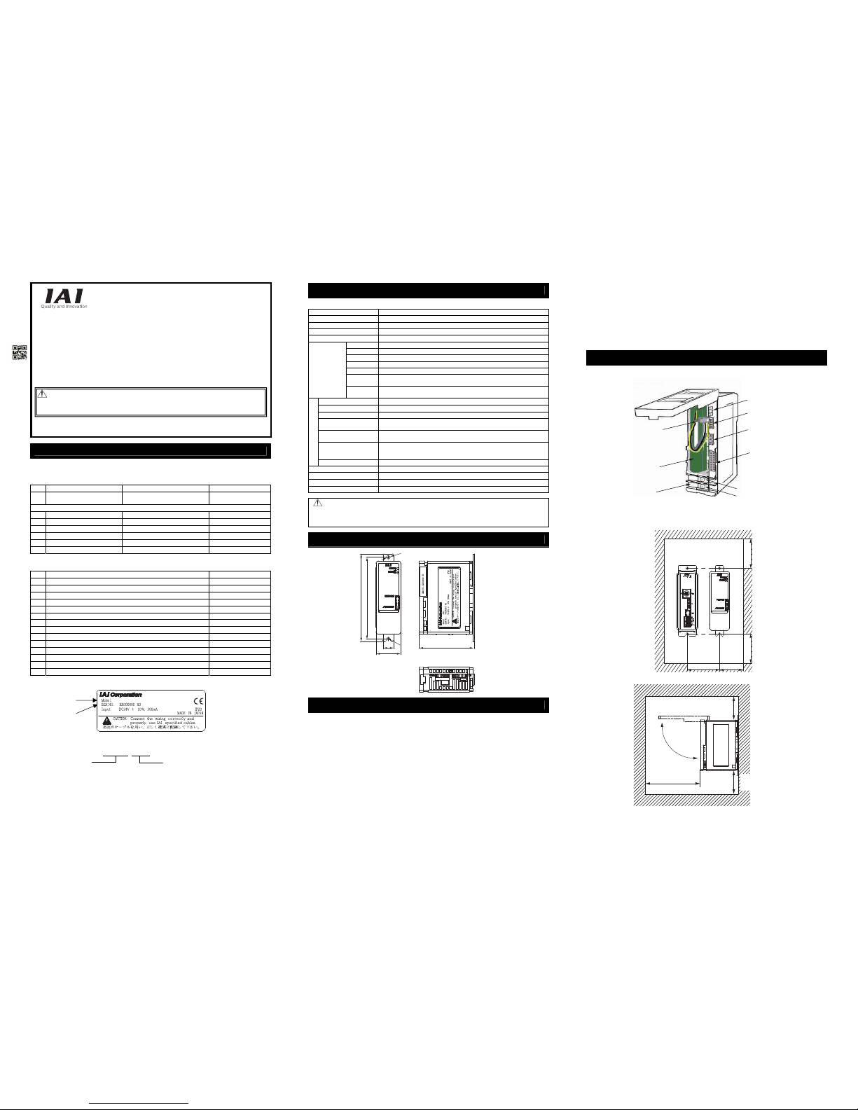
Status Indicator LEDs
Enclosed connector for
backup battery connection
Backup Battery
(Ni-MH Battery)
Power Supply Terminal
(24V DC)
Setting Switch (DIP switch)
Backup Battery Connector
Connector to connect
with host controller
+
−
Simple Absolute Unit
ACON/PCON/PSEL-ABU
First Step Guide Third Edition
Thank you for purchasing our product.
Make sure to read the Safety Guide and detailed Instruction Manual (CD/DVD) included with the product in
addition to this First Step Guide to ensure correct use.
This Instruction Manual is original.
• Using or copying all or part of this Instruction Manual without permission is prohibited.
• The company names, names of products and trademarks of each company shown in the sentences are
registered trademarks.
This product is comprised of the following parts if it is of standard configuration.
If you find any fault in the contained model or any missing parts, contact us or our distributor.
1. Parts
2. Instruction Manuals related to this product, which are contained in the Instruction Manual
(CD/DVD).
No. Name Manual No.
1 Simple Absolute Unit Instruction Manual ME0179
2 ACON-C/CG Controller Instruction Manual ME0176
3 PCON-C/CG/CF Controller Positioner Type Instruction Manual ME0170
4 ACON-CY Controller Instruction Manual ME0167
5 PCON-CY Controller Instruction Manual ME0156
6 ACON-SE Controller Instruction Manual ME0171
7 PCON-SE Controller Instruction Manual ME0163
8 PSEL Controller Instruction Manual ME0172
9 PC Software
RCM-101-MW/ RCM-101-USB Instruction Manual
ME0155
10 Touch Panel Teaching CON-PT/PD/PG Instruction Manual ME0227
11 Teaching Pendant CON-T/TG Instruction Manual ME0178
12
Simple Teaching Pendant
RCM-E Instruction Manual ME0174
13 Data Setter RCM-P Instruction Manual ME0175
14 Touch Panel Display RCM-PM-01 Instruction Manual ME0182
3. How to read the model plate
4. How to read the model
Using Simple Absolute R Unit enables to make the applicable control axes to the absolute system.
Item Specifications
Power Supply
24V DC±10%
Current Consumption 300mA or less (It gets the highest when charging battery)
Heat Generation 7.2W
Number of Controllable Axes 1-axis
Name Ni-MH battery
Model AB-7
Supplier FDK Corporation
Rated 3.6V 3300mAh
Nominal 3.6V 3700mAh
Product Life
About 3 years (reference) It varies significantly by the effects of the usage
condition (especially temperature).
Backup Battery
(Absolute
Battery)
Charging
Time
About 72 hours
Surrounding air temperature
0 to 40°C
Surrounding humidity 95%RH or less (non-condensing)
Surrounding environment [Refer to Installation Environment section]
Surrounding storage
temperature
-25 to 70°C
Surrounding storage
humidity
95%RH or less (non-condensing)
Vibration durability
XYZ Each direction 10 to 57Hz Pulsating amplitude 0.035mm (continuous)
0.075mm (intermittent)
57 to 150Hz 4.9m/s
2
(continuous) 9.8m/s2 (intermittent)
Environment
Protection class IP20
Cooling Method Natural Air Cooling
Insulation Resistance
Between power supply terminal and FG 500V DC 10MΩ or more
External Dimensions
34W × 105H × 73.3D [mm]
Weight Approx. 312g (including backup battery)
Note : Please have the battery charged for more than 72 hours before using for the first time or after replacing with a
new one. (Keep the ABU power ON. Operating the actuator during the battery charge would not cause any
problem.)
Also charge the battery when the ABU power is OFF for more than the battery retention time.
[Refer to Absolute Battery Retention Time Condition Setting section for the details of the battery retention time.]
This product is capable for use in the environment of pollution degree 2*1 or equivalent.
*1 Pollution Degree 2 : Environment that may cause non-conductive pollution or transient conductive pollution b y
frost. (IEC60664-1)
1. Installation Environment
Do not use this product in the following environment.
• Location where the surroundi ng air temperature exceeds the range of 0 to 40°C
• Location where condensatio n occurs due to abrupt temperature changes
• Location where relative humi dity exceeds 85%RH
• Location exposed to corrosi ve gases or combustible gases
• Location exposed to significa nt amount of dust, salt or iron powder
• Location subject to direct vibration or impact
• Location exposed to direct sunlight
• Location where the product m ay come in contact with water, oil or chemical droplets
• Environment that blocks the air vent [Refer to Installation and Noise Elimination Section]
When using the product in any of the locations specified below, provide a sufficient shield.
• Location subject to electrostat ic noise
• Location where high electrical or magnetic field is present
• Location with the mains or po wer lines passing nearby
2. Storage and Preservation Environment
The storage and preservation environment should comply with the same standards as those for the installation
environment. In particular, when the machine is to be stored for a long time, pay close attention to environmental
conditions so that no condensation forms. Unless specially specified, moisture absorbency protection is not
included in the package when the machine is delivered. In the case that the machine is to be stored and
preserved in an environment where condensation is anticipated, take the condensation preventive measures
from outside of the entire package, or directly after opening the package.
3. Installation
Design and Build the system considering the size of the controller box, location of the controller and cooling
factors to keep the ambient temperature around the controller below 40°C.
1. Names of the Parts
2. Installation
Product Check
No. Part Name Model Reference
1 Controller Main Body
Refer to “How to read the model
plate”, “How to read the model”
Accessories
2 Backup Battery AB-7 1 pc
3 ACON Connection Cable CB-AC-PJ002 For ACON controller
4 PCON/PSEL Connection Cable CB-PC-PJ002
For PCON/PSEL controller
5 First Step Guide
6 Instruction Manual (CD/DVD)
7 Safety Guide
Basic Specifications
External Dimensions
Installation Environment
Names of the Parts and Installation
ACON-ABU
<Controller Model Code>
ACON : For ACON controller
PCON : For PCON/PSEL controller
<Series Name>
Main body + Battery + Cable Set Model Code
Model
Serial number
ACON-ABU
φ
5
120
112
R2.5
15
34
75.3
Min.55 Min.40
Min.50 Min.50
Min.80
It is necessary to have a room
to open/close the front cover.
Min.50
Ensure enough
space for wiring.
Warning : Operation of this equipment requires detailed installation and operation instructions
which are provided on the CD/DVD Manual included in the box this device was
packaged in. It should be retained with this device at all times.
A hardcopy of the Manual can be requested by contacting your nearest IAI Sales Office
listed at the back cove
r
of the Instruction Manual or on the First Step Guide.
Page 2
Absolute Battery Retention Time Condition Setting
Setting Switch
It is able to limit the current consumption assuming the possibility of transient encoder rotation movement
occurred during the power is OFF so the retention time of the current values by the backup battery can last
as much as possible.
Also, make sure the enclosed connector for backup battery connection is removed from the Simple
Absolute Unit when conducting this operation.
Setting Switch
Switch Function Set in delivery
1
For the encoder rotation speed setting secured by the
absolute while the power is OFF
OFF
2
For the encoder rotation speed setting secured by the
absolute while the power is OFF
ON
3 For updating (Keep it OFF while in use.) OFF
4
Not for use (Keep it ON while in use. Turning it OFF will
issue a wire breakage error.)
ON
Encoder allowable max. rotation speed setting possibly be occurred while the
power is OFF
Setting
Switch
Encoder Max. Rotation Speed [rpm]
1 2
When the connected
actuator is a model
other than RCA2-***N;
When the connected
actuator is RCA2-***N;
Battery Retention Time
(reference)
OFF OFF 100 75 20 days
ON OFF 200 150 15 days
OFF ON 400 300 10 days (Set in delivery)
ON ON 800 600 5 days
The retention times described above are the reference assuming that the backup battery is used for the first
time under the room temperature (20°C) and there is no encoder rotation while the power is OFF or the
operation is transient of a single encoder.
Note : In the following cases, the absolute data (current position data) cannot be guaranteed. Be careful.
1) When the number of encoder rotation exceeded the set value while the power is OFF.
2) When the operation is continued through even though the number of encoder rotation is within the set value.
This function is purposed to guarantee the absolute data (current position data) in a case the encoder is
rotated unexpectedly on the assumption that the actuator would not move while the power is OFF.
3) When the backup battery is already exhausted.
Regarding Electric Charge and Discharge
Before using for the first time or after the battery replacement, charge the battery for 72 hours or more
continuously.
While 24V is supplied to the controller, the battery is charged.
1-hour battery charge enables to retain the encoder data for the duration indicated in the following table
(Note)
.
Leaving the controller turned OFF for more than the data retainable duration will cause to lose the data.
Charge the battery as early as possible.
The battery has its product life. The data retainable time decreases as the battery life gets consumed.
Replace the battery with a new one if a big drop of the retainable time is confirmed.
(Note) Data retainable time per hour of battery charge
* Values shown in the table are reference time assuming the battery is new.
Setting of encoder maximum rotation speed 100 (75) 200 (150) 400 (300) 800 (600)
Data Holding Time (reference) 6.6H 5.0H 3.3H 1.6H
Wiring
1. Connection of Power Supply
Simple absolute Unit requires 24V DC power to be supplied for the purposes such as to charge the
backup battery.
2. Connection of Backup Battery
Connect the connector enclosed to the backup battery.
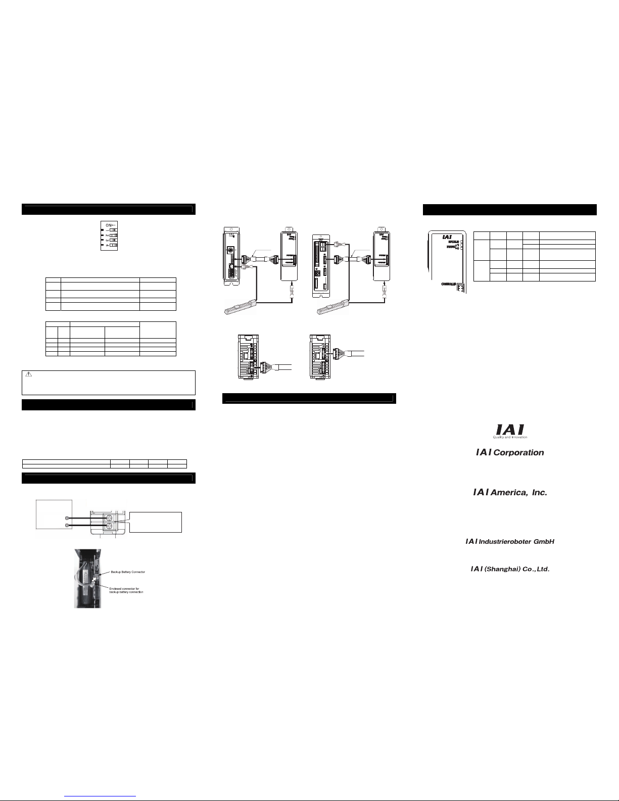
3. Connection to Controller and Actuator
ACON and PCON/PSEL have the encoder connector plug in the different position from each other. Pay
special attention to connect the cable to the right ones.
• When connecting with ACON • When connecting with PCON or PSEL
Absolute Reset
Refer to Instruction Manual (CD) for the details of how to perform an absolute reset.
1. When using a teaching tool
It is a way to perform an absolute reset using a teaching tool such as the PC software and teaching
pendant.
(1) Parameter Check and Settings
For ACON and PCON, set Parameter No. 83 ABS Unit [0: Not used, 1: Used] to “1”. For PSEL, set
Axis Parameter No. 38 Encoder ABS/INC Type [0: INC, 1: ABS] to “1”.
If you purchased a controller and Simple Absolute Unit together, the parameter should already be set
as described above at the delivery. Please confirm it is set as it is described in case.
(2) Alarm Reset
When a teaching tool is connected, a message of “0EE: Absolute Encoder Error” for ACON and
PCON, and “41C: ABS Unit Encoder Error (2)” for PSEL will appear. Reset the alarm.
(3) Home Return (Absolute Reset)
Turn the servo ON and execute a home-return operation for ACON and PCON. The absolute reset
process is finished once the home-return operation is completed.
For PSEL, follow the steps of the absolute reset shown in the menu on the teaching tool.
2. When Using PIO (for ACON and PCON-C/CG/CY only)
It is a way to perform an absolute reset using the PIO (24V I/O) control signal.
(1) Parameter Check and Settings
For ACON and PCON, set Parameter No. 83 ABS Unit [0: Not used, 1: Used] to “1”.
If you purchased a controller and Simple Absolute Unit together, the parameter should already be set
as described above at the delivery. Please confirm it is set as it is described in case.
(2) Alarm Reset
When the controller gets turned ON, an alarm “0EE: Absolute Encoder Error” will appear. Turn ON
the alarm reset signal of PIO to reset the alarm.
(3) Servo ON
Turn ON the pause signal if it exists in the PIO patterns. Turn ON the servo-on signal of PIO. If the
process has been carried out in a normal condition, SV lamp on the front panel turns on in green.
(4) Home Return (Absolute Reset)
Turn ON the home return signal of PIO to execute a home-return operation. The absolute reset is
finished if the home-return operation completes in normal condition and home return complete signal
turns ON.
There are monitor LEDs provided on simple absolute unit for status monitoring. On these LEDs, it is possible
to check the unit status at the startup or when there is any trouble.
LED
Displayed
Color
LED
Displayed
Color
Description
GN Absolute reset complete
GN STATUS1
RD Absolute reset incomplete
RDY/ALM
RD STATUS1 RD
Circuit error, Please contact us if the
error does not recover even after a
reboot.
GN – –
Absolute battery is 4.2V or more (fully
charged)
OR – – Absolute battery less than 3.2V to 4.2V
STATUS0
RD – –
Absolute battery is 3.2V or less
(not connected or voltage is dropped)
Head Office: 577-1 Obane Shimizu-KU Shizuoka City Shizuoka 424-0103, Japan
TEL+81-54-364-5105 FAX+81-54-364-2589
website: www.iai-robot.co.jp/
Ober der Röth 4, D-65824 Schwalbach am Taunus, Germany
TEL 06196-88950 FAX 06196-889524
SHANGHAI JIAHUA BUSINESS CENTER A8-303, 808, Hongqiao Rd. Shanghai 200030, China
TEL 021-6448-4753 FAX 021-6448-3992
website: www.iai-robot.com
Technical Support available in USA, Europe and China
Head Office: 2690 W, 237th Street Torrance, CA 90505
TEL (310) 891-6015 FAX (310) 891-0815
Chicago Office: 1261 Hamilton Parkway Itasca, IL 60143
TEL (630) 467-9900 FAX (630) 467-9912
TEL (678) 354-9470 FAX (678) 354-9471
website: www.intelligentactuator.com
Atlanta Office: 1220 Kennestone Circle Suite 108 Marietta, GA 30066
Troubleshooting
Front Cover Side Front Cover Side
Bottom Side of Simple Absolute Unit Bottom Side of Simple Absolute Unit
Encoder Cable
Encoder Cable
Left side is ON
Controller Simple Absolute Unit
Connection
Cable
Encoder Cable
Motor Cable
Actuator
Controller
Simple Absolute Unit
Connection
Cable
Encoder Cable
Motor Cable
Actuator
Manual No.: ME0286-3A
Simple Absolite Unit
24V DC
Power Supply
24V
0V
(Max. 300mA)
Applicable Wire AWG18 (copper wire)
Solid wire : φ1.0
Twisted wire : 0.8mm
2
Terminal Ring tongue terminal for
M3 with width 6mm or less
 Loading...