

Page 1

MSEL Controller
Instruction Manual Fifth Edition
Page 2

Page 3

Please Read Before Use
Thank you for purchasing our product.
This Instruction Manual describes all necessary information items to operate this product safely
such as the operation procedure, structure and maintenance procedure.
To ensure the safe operation of this product, please read and fully understand this manual.
The enclosed DVD in this product package includes the Instruction Manual for this product.
For the operation of this product, print out the necessary sections in the Instruction Manual or
display them using the personal computer.
After reading through this manual, keep this Instruction Manual at hand so that the operator of this
product can read it whenever necessary.
[Important]
This Instruction Manual is original.
The product cannot be operated in any way unless expressly specified in this Instruction
Manual. IAI shall assume no responsibility for the outcome of any operation not specified
herein.
Information contained in this Instruction Manual is subject to change without notice for the
purpose of product improvement.
If you have any question or comment regarding the content of this manual, please contact
the IAI sales office near you.
Using or copying all or part of this Instruction Manual without permission is prohibited.
The company names, names of products and trademarks of each company shown in the
sentences are registered trademarks.
Page 4

Page 5

Table of Contents
Safety Guide ꞏꞏꞏꞏꞏꞏꞏꞏꞏꞏꞏꞏꞏꞏꞏꞏꞏꞏꞏꞏꞏꞏꞏꞏꞏꞏꞏꞏꞏꞏꞏꞏꞏꞏꞏꞏꞏꞏꞏꞏꞏꞏꞏꞏꞏꞏꞏꞏꞏꞏꞏꞏꞏꞏꞏꞏꞏꞏꞏꞏꞏꞏꞏꞏꞏꞏꞏꞏꞏꞏꞏꞏꞏꞏꞏꞏꞏꞏꞏꞏꞏꞏꞏꞏꞏꞏꞏꞏꞏꞏꞏꞏꞏꞏꞏꞏꞏꞏ1
Controller Model Codes and Applicable Actuators ꞏꞏꞏꞏꞏꞏꞏꞏꞏꞏꞏꞏꞏꞏꞏꞏꞏꞏꞏꞏꞏꞏꞏꞏꞏꞏꞏꞏꞏꞏꞏꞏꞏꞏꞏꞏꞏꞏꞏꞏꞏꞏꞏꞏꞏꞏꞏꞏꞏꞏ8
Precautions in Operation ꞏꞏꞏꞏꞏꞏꞏꞏꞏꞏꞏꞏꞏꞏꞏꞏꞏꞏꞏꞏꞏꞏꞏꞏꞏꞏꞏꞏꞏꞏꞏꞏꞏꞏꞏꞏꞏꞏꞏꞏꞏꞏꞏꞏꞏꞏꞏꞏꞏꞏꞏꞏꞏꞏꞏꞏꞏꞏꞏꞏꞏꞏꞏꞏꞏꞏꞏꞏꞏꞏꞏꞏꞏꞏꞏꞏꞏꞏꞏꞏꞏꞏ9
International Standards Compliances ꞏꞏꞏꞏꞏꞏꞏꞏꞏꞏꞏꞏꞏꞏꞏꞏꞏꞏꞏꞏꞏꞏꞏꞏꞏꞏꞏꞏꞏꞏꞏꞏꞏꞏꞏꞏꞏꞏꞏꞏꞏꞏꞏꞏꞏꞏꞏꞏꞏꞏꞏꞏꞏꞏꞏꞏꞏꞏꞏꞏꞏꞏꞏꞏ12
Name for Each Parts and Their Functions ꞏꞏꞏꞏꞏꞏꞏꞏꞏꞏꞏꞏꞏꞏꞏꞏꞏꞏꞏꞏꞏꞏꞏꞏꞏꞏꞏꞏꞏꞏꞏꞏꞏꞏꞏꞏꞏꞏꞏꞏꞏꞏꞏꞏꞏꞏꞏꞏꞏꞏꞏꞏꞏꞏꞏꞏꞏꞏ 13
Actuator Axesꞏꞏꞏꞏꞏꞏꞏꞏꞏꞏꞏꞏꞏꞏꞏꞏꞏꞏꞏꞏꞏꞏꞏꞏꞏꞏꞏꞏꞏꞏꞏꞏꞏꞏꞏꞏꞏꞏꞏꞏꞏꞏꞏꞏꞏꞏꞏꞏꞏꞏꞏꞏꞏꞏꞏꞏꞏꞏꞏꞏꞏꞏꞏꞏꞏꞏꞏꞏꞏꞏꞏꞏꞏꞏꞏꞏꞏꞏꞏꞏꞏꞏꞏꞏꞏꞏꞏꞏꞏꞏꞏꞏꞏꞏꞏ17
Chapter 1
Specifications Checkꞏꞏꞏꞏꞏꞏꞏꞏꞏꞏꞏꞏꞏꞏꞏꞏꞏꞏꞏꞏꞏꞏꞏꞏꞏꞏꞏꞏꞏꞏꞏꞏꞏꞏꞏꞏꞏꞏꞏꞏꞏꞏꞏꞏꞏꞏꞏꞏꞏꞏꞏꞏꞏꞏꞏꞏꞏꞏꞏꞏꞏꞏꞏꞏꞏꞏꞏꞏꞏꞏ 23
1.1 Product Checkꞏꞏꞏꞏꞏꞏꞏꞏꞏꞏꞏꞏꞏꞏꞏꞏꞏꞏꞏꞏꞏꞏꞏꞏꞏꞏꞏꞏꞏꞏꞏꞏꞏꞏꞏꞏꞏꞏꞏꞏꞏꞏꞏꞏꞏꞏꞏꞏꞏꞏꞏꞏꞏꞏꞏꞏꞏꞏꞏꞏꞏꞏꞏꞏꞏꞏꞏꞏꞏꞏꞏꞏꞏꞏꞏꞏꞏꞏꞏꞏꞏꞏꞏꞏꞏꞏꞏ 23
1.1.1 Parts (Excluding Options) ꞏꞏꞏꞏꞏꞏꞏꞏꞏꞏꞏꞏꞏꞏꞏꞏꞏꞏꞏꞏꞏꞏꞏꞏꞏꞏꞏꞏꞏꞏꞏꞏꞏꞏꞏꞏꞏꞏꞏꞏꞏꞏꞏꞏꞏꞏꞏꞏꞏꞏꞏꞏꞏꞏꞏꞏꞏꞏꞏꞏꞏꞏꞏꞏꞏ 23
1.1.2 Teaching Tool (Optional)ꞏꞏꞏꞏꞏꞏꞏꞏꞏꞏꞏꞏꞏꞏꞏꞏꞏꞏꞏꞏꞏꞏꞏꞏꞏꞏꞏꞏꞏꞏꞏꞏꞏꞏꞏꞏꞏꞏꞏꞏꞏꞏꞏꞏꞏꞏꞏꞏꞏꞏꞏꞏꞏꞏꞏꞏꞏꞏꞏꞏꞏꞏꞏꞏꞏꞏꞏꞏ 23
1.1.3 Instruction Manuals Related to this Product, which are Contained in the
Instruction Manual (DVD). ꞏꞏꞏꞏꞏꞏꞏꞏꞏꞏꞏꞏꞏꞏꞏꞏꞏꞏꞏꞏꞏꞏꞏꞏꞏꞏꞏꞏꞏꞏꞏꞏꞏꞏꞏꞏꞏꞏꞏꞏꞏꞏꞏꞏꞏꞏꞏꞏꞏꞏꞏꞏꞏꞏꞏꞏꞏꞏꞏꞏꞏꞏꞏꞏꞏ 24
1.1.4 How to Read the Model Plateꞏꞏꞏꞏꞏꞏꞏꞏꞏꞏꞏꞏꞏꞏꞏꞏꞏꞏꞏꞏꞏꞏꞏꞏꞏꞏꞏꞏꞏꞏꞏꞏꞏꞏꞏꞏꞏꞏꞏꞏꞏꞏꞏꞏꞏꞏꞏꞏꞏꞏꞏꞏꞏꞏꞏꞏꞏꞏꞏꞏꞏ 24
1.1.5 How to Read the Model ꞏꞏꞏꞏꞏꞏꞏꞏꞏꞏꞏꞏꞏꞏꞏꞏꞏꞏꞏꞏꞏꞏꞏꞏꞏꞏꞏꞏꞏꞏꞏꞏꞏꞏꞏꞏꞏꞏꞏꞏꞏꞏꞏꞏꞏꞏꞏꞏꞏꞏꞏꞏꞏꞏꞏꞏꞏꞏꞏꞏꞏꞏꞏꞏꞏꞏꞏꞏ 24
1.2 Basic Specificationsꞏꞏꞏꞏꞏꞏꞏꞏꞏꞏꞏꞏꞏꞏꞏꞏꞏꞏꞏꞏꞏꞏꞏꞏꞏꞏꞏꞏꞏꞏꞏꞏꞏꞏꞏꞏꞏꞏꞏꞏꞏꞏꞏꞏꞏꞏꞏꞏꞏꞏꞏꞏꞏꞏꞏꞏꞏꞏꞏꞏꞏꞏꞏꞏꞏꞏꞏꞏꞏꞏꞏꞏꞏꞏꞏꞏꞏꞏꞏꞏ 27
1.2.1 Selection of the Circuit Breakerꞏꞏꞏꞏꞏꞏꞏꞏꞏꞏꞏꞏꞏꞏꞏꞏꞏꞏꞏꞏꞏꞏꞏꞏꞏꞏꞏꞏꞏꞏꞏꞏꞏꞏꞏꞏꞏꞏꞏꞏꞏꞏꞏꞏꞏꞏꞏꞏꞏꞏꞏꞏꞏꞏꞏꞏꞏꞏꞏ 28
1.2.2 Selection of the Leakage Breakerꞏꞏꞏꞏꞏꞏꞏꞏꞏꞏꞏꞏꞏꞏꞏꞏꞏꞏꞏꞏꞏꞏꞏꞏꞏꞏꞏꞏꞏꞏꞏꞏꞏꞏꞏꞏꞏꞏꞏꞏꞏꞏꞏꞏꞏꞏꞏꞏꞏꞏꞏꞏꞏꞏꞏꞏ 28
1.3 External Dimensions ꞏꞏꞏꞏꞏꞏꞏꞏꞏꞏꞏꞏꞏꞏꞏꞏꞏꞏꞏꞏꞏꞏꞏꞏꞏꞏꞏꞏꞏꞏꞏꞏꞏꞏꞏꞏꞏꞏꞏꞏꞏꞏꞏꞏꞏꞏꞏꞏꞏꞏꞏꞏꞏꞏꞏꞏꞏꞏꞏꞏꞏꞏꞏꞏꞏꞏꞏꞏꞏꞏꞏꞏꞏꞏꞏꞏꞏꞏꞏ 29
1.4 Interfaces ꞏꞏꞏꞏꞏꞏꞏꞏꞏꞏꞏꞏꞏꞏꞏꞏꞏꞏꞏꞏꞏꞏꞏꞏꞏꞏꞏꞏꞏꞏꞏꞏꞏꞏꞏꞏꞏꞏꞏꞏꞏꞏꞏꞏꞏꞏꞏꞏꞏꞏꞏꞏꞏꞏꞏꞏꞏꞏꞏꞏꞏꞏꞏꞏꞏꞏꞏꞏꞏꞏꞏꞏꞏꞏꞏꞏꞏꞏꞏꞏꞏꞏꞏꞏꞏꞏꞏꞏꞏꞏꞏꞏꞏ 30
1.4.1 Standard I/O ꞏꞏꞏꞏꞏꞏꞏꞏꞏꞏꞏꞏꞏꞏꞏꞏꞏꞏꞏꞏꞏꞏꞏꞏꞏꞏꞏꞏꞏꞏꞏꞏꞏꞏꞏꞏꞏꞏꞏꞏꞏꞏꞏꞏꞏꞏꞏꞏꞏꞏꞏꞏꞏꞏꞏꞏꞏꞏꞏꞏꞏꞏꞏꞏꞏꞏꞏꞏꞏꞏꞏꞏꞏꞏꞏꞏꞏꞏꞏꞏꞏꞏꞏ 30
1.4.2 Extension I/Oꞏꞏꞏꞏꞏꞏꞏꞏꞏꞏꞏꞏꞏꞏꞏꞏꞏꞏꞏꞏꞏꞏꞏꞏꞏꞏꞏꞏꞏꞏꞏꞏꞏꞏꞏꞏꞏꞏꞏꞏꞏꞏꞏꞏꞏꞏꞏꞏꞏꞏꞏꞏꞏꞏꞏꞏꞏꞏꞏꞏꞏꞏꞏꞏꞏꞏꞏꞏꞏꞏꞏꞏꞏꞏꞏꞏꞏꞏꞏꞏꞏꞏ 31
1.5 Absolute Battery Box (to be Connected for Simple Absolute Type) ꞏꞏꞏꞏꞏꞏꞏꞏꞏꞏꞏꞏꞏꞏꞏꞏꞏꞏꞏꞏ 32
1.6 Installation and Storage Environmentꞏꞏꞏꞏꞏꞏꞏꞏꞏꞏꞏꞏꞏꞏꞏꞏꞏꞏꞏꞏꞏꞏꞏꞏꞏꞏꞏꞏꞏꞏꞏꞏꞏꞏꞏꞏꞏꞏꞏꞏꞏꞏꞏꞏꞏꞏꞏꞏꞏꞏꞏꞏꞏꞏꞏꞏꞏꞏ 33
1.7 Noise Prevention and the Installationꞏꞏꞏꞏꞏꞏꞏꞏꞏꞏꞏꞏꞏꞏꞏꞏꞏꞏꞏꞏꞏꞏꞏꞏꞏꞏꞏꞏꞏꞏꞏꞏꞏꞏꞏꞏꞏꞏꞏꞏꞏꞏꞏꞏꞏꞏꞏꞏꞏꞏꞏꞏꞏꞏꞏꞏꞏꞏ 34
Chapter 2 Wiring ꞏꞏꞏꞏꞏꞏꞏꞏꞏꞏꞏꞏꞏꞏꞏꞏꞏꞏꞏꞏꞏꞏꞏꞏꞏꞏꞏꞏꞏꞏꞏꞏꞏꞏꞏꞏꞏꞏꞏꞏꞏꞏꞏꞏꞏꞏꞏꞏꞏꞏꞏꞏꞏꞏꞏꞏꞏꞏꞏꞏꞏꞏꞏꞏꞏꞏꞏꞏꞏꞏꞏꞏꞏꞏꞏꞏꞏꞏꞏꞏꞏꞏꞏꞏꞏꞏꞏꞏꞏ 37
2.1 Wiring (Example connection of devices) Diagram ꞏꞏꞏꞏꞏꞏꞏꞏꞏꞏꞏꞏꞏꞏꞏꞏꞏꞏꞏꞏꞏꞏꞏꞏꞏꞏꞏꞏꞏꞏꞏꞏꞏꞏꞏꞏꞏꞏꞏꞏꞏꞏ 37
2.2 Circuit Diagram (Example) ꞏꞏꞏꞏꞏꞏꞏꞏꞏꞏꞏꞏꞏꞏꞏꞏꞏꞏꞏꞏꞏꞏꞏꞏꞏꞏꞏꞏꞏꞏꞏꞏꞏꞏꞏꞏꞏꞏꞏꞏꞏꞏꞏꞏꞏꞏꞏꞏꞏꞏꞏꞏꞏꞏꞏꞏꞏꞏꞏꞏꞏꞏꞏꞏꞏꞏꞏꞏꞏꞏꞏ 39
2.2.1 Power Supply Circuit ꞏꞏꞏꞏꞏꞏꞏꞏꞏꞏꞏꞏꞏꞏꞏꞏꞏꞏꞏꞏꞏꞏꞏꞏꞏꞏꞏꞏꞏꞏꞏꞏꞏꞏꞏꞏꞏꞏꞏꞏꞏꞏꞏꞏꞏꞏꞏꞏꞏꞏꞏꞏꞏꞏꞏꞏꞏꞏꞏꞏꞏꞏꞏꞏꞏꞏꞏꞏꞏꞏꞏꞏ 39
2.2.2 Emergency Stop and Enable Circuit (PC/PCF/PCX Type)ꞏꞏꞏꞏꞏꞏꞏꞏꞏꞏꞏꞏꞏꞏꞏꞏꞏꞏꞏꞏꞏꞏꞏꞏꞏ 40
2.2.3 Emergency Stop and Enable Circuit (PG/PGF/PGX Type) ꞏꞏꞏꞏꞏꞏꞏꞏꞏꞏꞏꞏꞏꞏꞏꞏꞏꞏꞏꞏꞏꞏꞏꞏ 42
2.2.4 Motor Encoder Circuitꞏꞏꞏꞏꞏꞏꞏꞏꞏꞏꞏꞏꞏꞏꞏꞏꞏꞏꞏꞏꞏꞏꞏꞏꞏꞏꞏꞏꞏꞏꞏꞏꞏꞏꞏꞏꞏꞏꞏꞏꞏꞏꞏꞏꞏꞏꞏꞏꞏꞏꞏꞏꞏꞏꞏꞏꞏꞏꞏꞏꞏꞏꞏꞏꞏꞏꞏꞏꞏꞏꞏ 44
2.2.5 PIO Circuit ꞏꞏꞏꞏꞏꞏꞏꞏꞏꞏꞏꞏꞏꞏꞏꞏꞏꞏꞏꞏꞏꞏꞏꞏꞏꞏꞏꞏꞏꞏꞏꞏꞏꞏꞏꞏꞏꞏꞏꞏꞏꞏꞏꞏꞏꞏꞏꞏꞏꞏꞏꞏꞏꞏꞏꞏꞏꞏꞏꞏꞏꞏꞏꞏꞏꞏꞏꞏꞏꞏꞏꞏꞏꞏꞏꞏꞏꞏꞏꞏꞏꞏꞏꞏꞏ 46
2.2.6 Connection to Absolute Battery Box (only for PC/PG/PCF/PGF Type Simple
Absolute) ꞏꞏꞏꞏꞏꞏꞏꞏꞏꞏꞏꞏꞏꞏꞏꞏꞏꞏꞏꞏꞏꞏꞏꞏꞏꞏꞏꞏꞏꞏꞏꞏꞏꞏꞏꞏꞏꞏꞏꞏꞏꞏꞏꞏꞏꞏꞏꞏꞏꞏꞏꞏꞏꞏꞏꞏꞏꞏꞏꞏꞏꞏꞏꞏꞏꞏꞏꞏꞏꞏꞏꞏꞏꞏꞏꞏꞏꞏꞏꞏꞏꞏꞏꞏꞏꞏꞏ 53
2.3 Wiring Method ꞏꞏꞏꞏꞏꞏꞏꞏꞏꞏꞏꞏꞏꞏꞏꞏꞏꞏꞏꞏꞏꞏꞏꞏꞏꞏꞏꞏꞏꞏꞏꞏꞏꞏꞏꞏꞏꞏꞏꞏꞏꞏꞏꞏꞏꞏꞏꞏꞏꞏꞏꞏꞏꞏꞏꞏꞏꞏꞏꞏꞏꞏꞏꞏꞏꞏꞏꞏꞏꞏꞏꞏꞏꞏꞏꞏꞏꞏꞏꞏꞏꞏꞏꞏꞏꞏꞏ 54
2.3.1 Connection to AC Power Input Connector ꞏꞏꞏꞏꞏꞏꞏꞏꞏꞏꞏꞏꞏꞏꞏꞏꞏꞏꞏꞏꞏꞏꞏꞏꞏꞏꞏꞏꞏꞏꞏꞏꞏꞏꞏꞏꞏꞏꞏꞏꞏꞏꞏꞏꞏ 54
2.3.2 Wiring the Emergency Stop Circuit (System I/O)ꞏꞏꞏꞏꞏꞏꞏꞏꞏꞏꞏꞏꞏꞏꞏꞏꞏꞏꞏꞏꞏꞏꞏꞏꞏꞏꞏꞏꞏꞏꞏꞏꞏꞏꞏꞏꞏ 55
2.3.3 Wiring for Actuator ꞏꞏꞏꞏꞏꞏꞏꞏꞏꞏꞏꞏꞏꞏꞏꞏꞏꞏꞏꞏꞏꞏꞏꞏꞏꞏꞏꞏꞏꞏꞏꞏꞏꞏꞏꞏꞏꞏꞏꞏꞏꞏꞏꞏꞏꞏꞏꞏꞏꞏꞏꞏꞏꞏꞏꞏꞏꞏꞏꞏꞏꞏꞏꞏꞏꞏꞏꞏꞏꞏꞏꞏꞏꞏꞏ 56
2.3.4 Wiring for Motor Driving Power Line Connector ꞏꞏꞏꞏꞏꞏꞏꞏꞏꞏꞏꞏꞏꞏꞏꞏꞏꞏꞏꞏꞏꞏꞏꞏꞏꞏꞏꞏꞏꞏꞏꞏꞏꞏꞏꞏꞏꞏ 57
2.3.5 Wiring to Single Absolute Battery Unit ꞏꞏꞏꞏꞏꞏꞏꞏꞏꞏꞏꞏꞏꞏꞏꞏꞏꞏꞏꞏꞏꞏꞏꞏꞏꞏꞏꞏꞏꞏꞏꞏꞏꞏꞏꞏꞏꞏꞏꞏꞏꞏꞏꞏꞏꞏꞏꞏꞏꞏ 57
2.3.6 Wiring for PIOꞏꞏꞏꞏꞏꞏꞏꞏꞏꞏꞏꞏꞏꞏꞏꞏꞏꞏꞏꞏꞏꞏꞏꞏꞏꞏꞏꞏꞏꞏꞏꞏꞏꞏꞏꞏꞏꞏꞏꞏꞏꞏꞏꞏꞏꞏꞏꞏꞏꞏꞏꞏꞏꞏꞏꞏꞏꞏꞏꞏꞏꞏꞏꞏꞏꞏꞏꞏꞏꞏꞏꞏꞏꞏꞏꞏꞏꞏꞏꞏꞏ 58
2.3.7 Wiring for the Teaching Tool (SIO Connector, USB Connector) ꞏꞏꞏꞏꞏꞏꞏꞏꞏꞏꞏꞏꞏꞏꞏꞏꞏꞏ 59
Chapter 3 Operationꞏꞏꞏꞏꞏꞏꞏꞏꞏꞏꞏꞏꞏꞏꞏꞏꞏꞏꞏꞏꞏꞏꞏꞏꞏꞏꞏꞏꞏꞏꞏꞏꞏꞏꞏꞏꞏꞏꞏꞏꞏꞏꞏꞏꞏꞏꞏꞏꞏꞏꞏꞏꞏꞏꞏꞏꞏꞏꞏꞏꞏꞏꞏꞏꞏꞏꞏꞏꞏꞏꞏꞏꞏꞏꞏꞏꞏꞏꞏꞏꞏꞏꞏꞏꞏ 61
3.1 Types of Operationsꞏꞏꞏꞏꞏꞏꞏꞏꞏꞏꞏꞏꞏꞏꞏꞏꞏꞏꞏꞏꞏꞏꞏꞏꞏꞏꞏꞏꞏꞏꞏꞏꞏꞏꞏꞏꞏꞏꞏꞏꞏꞏꞏꞏꞏꞏꞏꞏꞏꞏꞏꞏꞏꞏꞏꞏꞏꞏꞏꞏꞏꞏꞏꞏꞏꞏꞏꞏꞏꞏꞏꞏꞏꞏꞏꞏꞏꞏꞏꞏ 61
3.2 Receiving and Forwarding of I/O Signals Necessary for Operation ꞏꞏꞏꞏꞏꞏꞏꞏꞏꞏꞏꞏꞏꞏꞏꞏꞏꞏꞏꞏ 62
3.3 Starting the Controllerꞏꞏꞏꞏꞏꞏꞏꞏꞏꞏꞏꞏꞏꞏꞏꞏꞏꞏꞏꞏꞏꞏꞏꞏꞏꞏꞏꞏꞏꞏꞏꞏꞏꞏꞏꞏꞏꞏꞏꞏꞏꞏꞏꞏꞏꞏꞏꞏꞏꞏꞏꞏꞏꞏꞏꞏꞏꞏꞏꞏꞏꞏꞏꞏꞏꞏꞏꞏꞏꞏꞏꞏꞏꞏꞏꞏꞏꞏ 65
3.3.1 Turning on the Power and Cutoffꞏꞏꞏꞏꞏꞏꞏꞏꞏꞏꞏꞏꞏꞏꞏꞏꞏꞏꞏꞏꞏꞏꞏꞏꞏꞏꞏꞏꞏꞏꞏꞏꞏꞏꞏꞏꞏꞏꞏꞏꞏꞏꞏꞏꞏꞏꞏꞏꞏꞏꞏꞏꞏꞏꞏꞏꞏ 65
3.3.2 Panel Window Display ꞏꞏꞏꞏꞏꞏꞏꞏꞏꞏꞏꞏꞏꞏꞏꞏꞏꞏꞏꞏꞏꞏꞏꞏꞏꞏꞏꞏꞏꞏꞏꞏꞏꞏꞏꞏꞏꞏꞏꞏꞏꞏꞏꞏꞏꞏꞏꞏꞏꞏꞏꞏꞏꞏꞏꞏꞏꞏꞏꞏꞏꞏꞏꞏꞏꞏꞏꞏꞏꞏ 66
3.3.3 Status LEDꞏꞏꞏꞏꞏꞏꞏꞏꞏꞏꞏꞏꞏꞏꞏꞏꞏꞏꞏꞏꞏꞏꞏꞏꞏꞏꞏꞏꞏꞏꞏꞏꞏꞏꞏꞏꞏꞏꞏꞏꞏꞏꞏꞏꞏꞏꞏꞏꞏꞏꞏꞏꞏꞏꞏꞏꞏꞏꞏꞏꞏꞏꞏꞏꞏꞏꞏꞏꞏꞏꞏꞏꞏꞏꞏꞏꞏꞏꞏꞏꞏꞏꞏꞏꞏ 68
3.3.4 Position Table and Program Creation and Writing ꞏꞏꞏꞏꞏꞏꞏꞏꞏꞏꞏꞏꞏꞏꞏꞏꞏꞏꞏꞏꞏꞏꞏꞏꞏꞏꞏꞏꞏꞏꞏꞏꞏꞏꞏ 70
Page 6

3.4 Program Operation ꞏꞏꞏꞏꞏꞏꞏꞏꞏꞏꞏꞏꞏꞏꞏꞏꞏꞏꞏꞏꞏꞏꞏꞏꞏꞏꞏꞏꞏꞏꞏꞏꞏꞏꞏꞏꞏꞏꞏꞏꞏꞏꞏꞏꞏꞏꞏꞏꞏꞏꞏꞏꞏꞏꞏꞏꞏꞏꞏꞏꞏꞏꞏꞏꞏꞏꞏꞏꞏꞏꞏꞏꞏꞏꞏꞏꞏꞏꞏꞏꞏ 71
3.4.1 Auto Start upon Power Onꞏꞏꞏꞏꞏꞏꞏꞏꞏꞏꞏꞏꞏꞏꞏꞏꞏꞏꞏꞏꞏꞏꞏꞏꞏꞏꞏꞏꞏꞏꞏꞏꞏꞏꞏꞏꞏꞏꞏꞏꞏꞏꞏꞏꞏꞏꞏꞏꞏꞏꞏꞏꞏꞏꞏꞏꞏꞏꞏꞏꞏꞏꞏꞏꞏ 71
3.4.2 Starting a Program by Specifying its Program Numberꞏꞏꞏꞏꞏꞏꞏꞏꞏꞏꞏꞏꞏꞏꞏꞏꞏꞏꞏꞏꞏꞏꞏꞏꞏꞏꞏꞏꞏ 73
3.4.3 7-Segment Display SEL Programꞏꞏꞏꞏꞏꞏꞏꞏꞏꞏꞏꞏꞏꞏꞏꞏꞏꞏꞏꞏꞏꞏꞏꞏꞏꞏꞏꞏꞏꞏꞏꞏꞏꞏꞏꞏꞏꞏꞏꞏꞏꞏꞏꞏꞏꞏꞏꞏꞏꞏꞏꞏꞏꞏꞏꞏ 74
Chapter 4 Home-Return / Absolute Reset ꞏꞏꞏꞏꞏꞏꞏꞏꞏꞏꞏꞏꞏꞏꞏꞏꞏꞏꞏꞏꞏꞏꞏꞏꞏꞏꞏꞏꞏꞏꞏꞏꞏꞏꞏꞏꞏꞏꞏꞏꞏꞏꞏꞏꞏꞏꞏꞏꞏꞏꞏꞏꞏꞏꞏꞏꞏ 77
4.1 Home-Return Preparation (Incremental Type)ꞏꞏꞏꞏꞏꞏꞏꞏꞏꞏꞏꞏꞏꞏꞏꞏꞏꞏꞏꞏꞏꞏꞏꞏꞏꞏꞏꞏꞏꞏꞏꞏꞏꞏꞏꞏꞏꞏꞏꞏꞏꞏꞏꞏꞏꞏꞏ 77
4.2 Absolute Reset Preparation (for Battery-less Absolute Type except for
SCARA Robot) ꞏꞏꞏꞏꞏꞏꞏꞏꞏꞏꞏꞏꞏꞏꞏꞏꞏꞏꞏꞏꞏꞏꞏꞏꞏꞏꞏꞏꞏꞏꞏꞏꞏꞏꞏꞏꞏꞏꞏꞏꞏꞏꞏꞏꞏꞏꞏꞏꞏꞏꞏꞏꞏꞏꞏꞏꞏꞏꞏꞏꞏꞏꞏꞏꞏꞏꞏꞏꞏꞏꞏꞏꞏꞏꞏꞏꞏꞏꞏꞏꞏꞏꞏꞏꞏꞏ 78
4.3 Absolute Reset for SCARA Robot (Battery-less Absolute Type) ꞏꞏꞏꞏꞏꞏꞏꞏꞏꞏꞏꞏꞏꞏꞏꞏꞏꞏꞏꞏꞏꞏꞏꞏ 81
4.3.1 Absolute Reset Preparation ꞏꞏꞏꞏꞏꞏꞏꞏꞏꞏꞏꞏꞏꞏꞏꞏꞏꞏꞏꞏꞏꞏꞏꞏꞏꞏꞏꞏꞏꞏꞏꞏꞏꞏꞏꞏꞏꞏꞏꞏꞏꞏꞏꞏꞏꞏꞏꞏꞏꞏꞏꞏꞏꞏꞏꞏꞏꞏꞏꞏꞏꞏꞏ 82
4.4 Simple Absolute Type (PC/PG/PCF/PGF Type Dedicated)ꞏꞏꞏꞏꞏꞏꞏꞏꞏꞏꞏꞏꞏꞏꞏꞏꞏꞏꞏꞏꞏꞏꞏꞏꞏꞏꞏꞏꞏꞏꞏ 90
4.4.1 Status LEDꞏꞏꞏꞏꞏꞏꞏꞏꞏꞏꞏꞏꞏꞏꞏꞏꞏꞏꞏꞏꞏꞏꞏꞏꞏꞏꞏꞏꞏꞏꞏꞏꞏꞏꞏꞏꞏꞏꞏꞏꞏꞏꞏꞏꞏꞏꞏꞏꞏꞏꞏꞏꞏꞏꞏꞏꞏꞏꞏꞏꞏꞏꞏꞏꞏꞏꞏꞏꞏꞏꞏꞏꞏꞏꞏꞏꞏꞏꞏꞏꞏꞏꞏꞏꞏ 90
4.4.2 Absolute Reset Preparation ꞏꞏꞏꞏꞏꞏꞏꞏꞏꞏꞏꞏꞏꞏꞏꞏꞏꞏꞏꞏꞏꞏꞏꞏꞏꞏꞏꞏꞏꞏꞏꞏꞏꞏꞏꞏꞏꞏꞏꞏꞏꞏꞏꞏꞏꞏꞏꞏꞏꞏꞏꞏꞏꞏꞏꞏꞏꞏꞏꞏꞏꞏꞏ 90
4.4.3 Simple Absolute Typeꞏꞏꞏꞏꞏꞏꞏꞏꞏꞏꞏꞏꞏꞏꞏꞏꞏꞏꞏꞏꞏꞏꞏꞏꞏꞏꞏꞏꞏꞏꞏꞏꞏꞏꞏꞏꞏꞏꞏꞏꞏꞏꞏꞏꞏꞏꞏꞏꞏꞏꞏꞏꞏꞏꞏꞏꞏꞏꞏꞏꞏꞏꞏꞏꞏꞏꞏꞏꞏꞏꞏ 91
4.4.4 Absolute Encoder Backup Type ꞏꞏꞏꞏꞏꞏꞏꞏꞏꞏꞏꞏꞏꞏꞏꞏꞏꞏꞏꞏꞏꞏꞏꞏꞏꞏꞏꞏꞏꞏꞏꞏꞏꞏꞏꞏꞏꞏꞏꞏꞏꞏꞏꞏꞏꞏꞏꞏꞏꞏꞏꞏꞏꞏꞏꞏꞏꞏ 92
4.4.5 Charging Absolute Battery ꞏꞏꞏꞏꞏꞏꞏꞏꞏꞏꞏꞏꞏꞏꞏꞏꞏꞏꞏꞏꞏꞏꞏꞏꞏꞏꞏꞏꞏꞏꞏꞏꞏꞏꞏꞏꞏꞏꞏꞏꞏꞏꞏꞏꞏꞏꞏꞏꞏꞏꞏꞏꞏꞏꞏꞏꞏꞏꞏꞏꞏꞏꞏꞏꞏ 92
4.4.6 Detection of Absolute Battery Voltage Drop ꞏꞏꞏꞏꞏꞏꞏꞏꞏꞏꞏꞏꞏꞏꞏꞏꞏꞏꞏꞏꞏꞏꞏꞏꞏꞏꞏꞏꞏꞏꞏꞏꞏꞏꞏꞏꞏꞏꞏꞏꞏꞏꞏ 93
Chapter 5 I/O Parameter ꞏꞏꞏꞏꞏꞏꞏꞏꞏꞏꞏꞏꞏꞏꞏꞏꞏꞏꞏꞏꞏꞏꞏꞏꞏꞏꞏꞏꞏꞏꞏꞏꞏꞏꞏꞏꞏꞏꞏꞏꞏꞏꞏꞏꞏꞏꞏꞏꞏꞏꞏꞏꞏꞏꞏꞏꞏꞏꞏꞏꞏꞏꞏꞏꞏꞏꞏꞏꞏꞏꞏꞏꞏꞏꞏꞏꞏꞏꞏ 95
5.1 I/O Parameters ꞏꞏꞏꞏꞏꞏꞏꞏꞏꞏꞏꞏꞏꞏꞏꞏꞏꞏꞏꞏꞏꞏꞏꞏꞏꞏꞏꞏꞏꞏꞏꞏꞏꞏꞏꞏꞏꞏꞏꞏꞏꞏꞏꞏꞏꞏꞏꞏꞏꞏꞏꞏꞏꞏꞏꞏꞏꞏꞏꞏꞏꞏꞏꞏꞏꞏꞏꞏꞏꞏꞏꞏꞏꞏꞏꞏꞏꞏꞏꞏꞏꞏꞏꞏꞏꞏ 97
5.2 All Axes Common Parametersꞏꞏꞏꞏꞏꞏꞏꞏꞏꞏꞏꞏꞏꞏꞏꞏꞏꞏꞏꞏꞏꞏꞏꞏꞏꞏꞏꞏꞏꞏꞏꞏꞏꞏꞏꞏꞏꞏꞏꞏꞏꞏꞏꞏꞏꞏꞏꞏꞏꞏꞏꞏꞏꞏꞏꞏꞏꞏꞏꞏꞏꞏꞏꞏꞏꞏ 113
5.3 Axis-Specific Parameters ꞏꞏꞏꞏꞏꞏꞏꞏꞏꞏꞏꞏꞏꞏꞏꞏꞏꞏꞏꞏꞏꞏꞏꞏꞏꞏꞏꞏꞏꞏꞏꞏꞏꞏꞏꞏꞏꞏꞏꞏꞏꞏꞏꞏꞏꞏꞏꞏꞏꞏꞏꞏꞏꞏꞏꞏꞏꞏꞏꞏꞏꞏꞏꞏꞏꞏꞏꞏꞏꞏꞏꞏ 119
5.4 Driver Card Parameters ꞏꞏꞏꞏꞏꞏꞏꞏꞏꞏꞏꞏꞏꞏꞏꞏꞏꞏꞏꞏꞏꞏꞏꞏꞏꞏꞏꞏꞏꞏꞏꞏꞏꞏꞏꞏꞏꞏꞏꞏꞏꞏꞏꞏꞏꞏꞏꞏꞏꞏꞏꞏꞏꞏꞏꞏꞏꞏꞏꞏꞏꞏꞏꞏꞏꞏꞏꞏꞏꞏꞏꞏꞏꞏ 127
5.5 Encoder Parameters ꞏꞏꞏꞏꞏꞏꞏꞏꞏꞏꞏꞏꞏꞏꞏꞏꞏꞏꞏꞏꞏꞏꞏꞏꞏꞏꞏꞏꞏꞏꞏꞏꞏꞏꞏꞏꞏꞏꞏꞏꞏꞏꞏꞏꞏꞏꞏꞏꞏꞏꞏꞏꞏꞏꞏꞏꞏꞏꞏꞏꞏꞏꞏꞏꞏꞏꞏꞏꞏꞏꞏꞏꞏꞏꞏꞏꞏꞏ130
5.6 I/O-Slot Card Parametersꞏꞏꞏꞏꞏꞏꞏꞏꞏꞏꞏꞏꞏꞏꞏꞏꞏꞏꞏꞏꞏꞏꞏꞏꞏꞏꞏꞏꞏꞏꞏꞏꞏꞏꞏꞏꞏꞏꞏꞏꞏꞏꞏꞏꞏꞏꞏꞏꞏꞏꞏꞏꞏꞏꞏꞏꞏꞏꞏꞏꞏꞏꞏꞏꞏꞏꞏꞏꞏꞏꞏꞏ131
5.7 Other Parametersꞏꞏꞏꞏꞏꞏꞏꞏꞏꞏꞏꞏꞏꞏꞏꞏꞏꞏꞏꞏꞏꞏꞏꞏꞏꞏꞏꞏꞏꞏꞏꞏꞏꞏꞏꞏꞏꞏꞏꞏꞏꞏꞏꞏꞏꞏꞏꞏꞏꞏꞏꞏꞏꞏꞏꞏꞏꞏꞏꞏꞏꞏꞏꞏꞏꞏꞏꞏꞏꞏꞏꞏꞏꞏꞏꞏꞏꞏꞏꞏꞏꞏ135
5.8 Parameters for Linear / Rotation Controls ꞏꞏꞏꞏꞏꞏꞏꞏꞏꞏꞏꞏꞏꞏꞏꞏꞏꞏꞏꞏꞏꞏꞏꞏꞏꞏꞏꞏꞏꞏꞏꞏꞏꞏꞏꞏꞏꞏꞏꞏꞏꞏꞏꞏꞏꞏꞏꞏꞏꞏꞏ139
5.9 Permission of SIO/PIO Program Startup with Password ꞏꞏꞏꞏꞏꞏꞏꞏꞏꞏꞏꞏꞏꞏꞏꞏꞏꞏꞏꞏꞏꞏꞏꞏꞏꞏꞏꞏꞏꞏꞏꞏꞏ 142
5.10 Parameter Setting (Applied)ꞏꞏꞏꞏꞏꞏꞏꞏꞏꞏꞏꞏꞏꞏꞏꞏꞏꞏꞏꞏꞏꞏꞏꞏꞏꞏꞏꞏꞏꞏꞏꞏꞏꞏꞏꞏꞏꞏꞏꞏꞏꞏꞏꞏꞏꞏꞏꞏꞏꞏꞏꞏꞏꞏꞏꞏꞏꞏꞏꞏꞏꞏꞏꞏꞏꞏꞏꞏꞏ 143
5.10.1 Want to Operate the System Tentatively Without Using I/Osꞏꞏꞏꞏꞏꞏꞏꞏꞏꞏꞏꞏꞏꞏꞏꞏꞏꞏꞏꞏꞏ 144
5.10.2 Want to Output an Auto Operation Determination Signal from the Controller ꞏꞏꞏ 144
5.10.3 Want to Retain Current Output Statuses Even during Emergency Stop ꞏꞏꞏꞏꞏꞏꞏ 144
5.10.4 Want to Start an Emergency Program ꞏꞏꞏꞏꞏꞏꞏꞏꞏꞏꞏꞏꞏꞏꞏꞏꞏꞏꞏꞏꞏꞏꞏꞏꞏꞏꞏꞏꞏꞏꞏꞏꞏꞏꞏꞏꞏꞏꞏꞏꞏꞏꞏꞏꞏꞏꞏꞏꞏ145
5.10.5 Want to Enable Auto Recovery (Restart) upon Cancellation of
Emergency Stopꞏꞏꞏꞏꞏꞏꞏꞏꞏꞏꞏꞏꞏꞏꞏꞏꞏꞏꞏꞏꞏꞏꞏꞏꞏꞏꞏꞏꞏꞏꞏꞏꞏꞏꞏꞏꞏꞏꞏꞏꞏꞏꞏꞏꞏꞏꞏꞏꞏꞏꞏꞏꞏꞏꞏꞏꞏꞏꞏꞏꞏꞏꞏꞏꞏꞏꞏꞏꞏꞏꞏꞏꞏꞏꞏꞏꞏ145
5.10.6 Want to Enable Auto Recovery (Error Reset) upon Cancellation of
Emergency Stopꞏꞏꞏꞏꞏꞏꞏꞏꞏꞏꞏꞏꞏꞏꞏꞏꞏꞏꞏꞏꞏꞏꞏꞏꞏꞏꞏꞏꞏꞏꞏꞏꞏꞏꞏꞏꞏꞏꞏꞏꞏꞏꞏꞏꞏꞏꞏꞏꞏꞏꞏꞏꞏꞏꞏꞏꞏꞏꞏꞏꞏꞏꞏꞏꞏꞏꞏꞏꞏꞏꞏꞏꞏꞏꞏꞏꞏ146
5.10.7 Want to Return to the Condition Immediately before Emergency Stop ꞏꞏꞏꞏꞏꞏꞏꞏ146
5.10.8 Want to Restart the Controller Externally ꞏꞏꞏꞏꞏꞏꞏꞏꞏꞏꞏꞏꞏꞏꞏꞏꞏꞏꞏꞏꞏꞏꞏꞏꞏꞏꞏꞏꞏꞏꞏꞏꞏꞏꞏꞏꞏꞏꞏꞏꞏꞏꞏꞏꞏ146
5.10.9 Want to Turn ON the Servo Externallyꞏꞏꞏꞏꞏꞏꞏꞏꞏꞏꞏꞏꞏꞏꞏꞏꞏꞏꞏꞏꞏꞏꞏꞏꞏꞏꞏꞏꞏꞏꞏꞏꞏꞏꞏꞏꞏꞏꞏꞏꞏꞏꞏꞏꞏꞏꞏꞏꞏ146
5.10.10 Want to Make a Home-Return on Actuators Externally ꞏꞏꞏꞏꞏꞏꞏꞏꞏꞏꞏꞏꞏꞏꞏꞏꞏꞏꞏꞏꞏꞏꞏꞏꞏꞏꞏꞏ 147
5.10.11 Want to Execute the Controller Program Externally ꞏꞏꞏꞏꞏꞏꞏꞏꞏꞏꞏꞏꞏꞏꞏꞏꞏꞏꞏꞏꞏꞏꞏꞏꞏꞏꞏꞏꞏꞏꞏꞏ147
5.10.12 Want to Execute a Program Externally by Making an Indication of
a Program Number in Binaryꞏꞏꞏꞏꞏꞏꞏꞏꞏꞏꞏꞏꞏꞏꞏꞏꞏꞏꞏꞏꞏꞏꞏꞏꞏꞏꞏꞏꞏꞏꞏꞏꞏꞏꞏꞏꞏꞏꞏꞏꞏꞏꞏꞏꞏꞏꞏꞏꞏꞏꞏꞏꞏꞏꞏꞏꞏꞏꞏꞏꞏ147
5.10.13 Want to Pause Controller Externally during Automatic Operation ꞏꞏꞏꞏꞏꞏꞏꞏꞏꞏꞏꞏꞏ147
5.10.14 Want to Reset Errors Externally ꞏꞏꞏꞏꞏꞏꞏꞏꞏꞏꞏꞏꞏꞏꞏꞏꞏꞏꞏꞏꞏꞏꞏꞏꞏꞏꞏꞏꞏꞏꞏꞏꞏꞏꞏꞏꞏꞏꞏꞏꞏꞏꞏꞏꞏꞏꞏꞏꞏꞏꞏꞏꞏꞏꞏꞏꞏ 148
5.10.15 Want to Change Input Port Assignmentsꞏꞏꞏꞏꞏꞏꞏꞏꞏꞏꞏꞏꞏꞏꞏꞏꞏꞏꞏꞏꞏꞏꞏꞏꞏꞏꞏꞏꞏꞏꞏꞏꞏꞏꞏꞏꞏꞏꞏꞏꞏꞏꞏꞏꞏꞏ148
5.10.16 Want to Change Output Port Assignments ꞏꞏꞏꞏꞏꞏꞏꞏꞏꞏꞏꞏꞏꞏꞏꞏꞏꞏꞏꞏꞏꞏꞏꞏꞏꞏꞏꞏꞏꞏꞏꞏꞏꞏꞏꞏꞏꞏꞏꞏꞏꞏꞏ 149
5.10.17 Want to Output that Home-Return (Home Position) Operation is Complete
on All Actuators ꞏꞏꞏꞏꞏꞏꞏꞏꞏꞏꞏꞏꞏꞏꞏꞏꞏꞏꞏꞏꞏꞏꞏꞏꞏꞏꞏꞏꞏꞏꞏꞏꞏꞏꞏꞏꞏꞏꞏꞏꞏꞏꞏꞏꞏꞏꞏꞏꞏꞏꞏꞏꞏꞏꞏꞏꞏꞏꞏꞏꞏꞏꞏꞏꞏꞏꞏꞏꞏꞏꞏꞏꞏꞏꞏꞏꞏꞏ 149
5.10.18 Want to Output the Error Level ꞏꞏꞏꞏꞏꞏꞏꞏꞏꞏꞏꞏꞏꞏꞏꞏꞏꞏꞏꞏꞏꞏꞏꞏꞏꞏꞏꞏꞏꞏꞏꞏꞏꞏꞏꞏꞏꞏꞏꞏꞏꞏꞏꞏꞏꞏꞏꞏꞏꞏꞏꞏꞏꞏꞏꞏꞏꞏ150
5.10.19 Want to Output the Emergency Stop Status ꞏꞏꞏꞏꞏꞏꞏꞏꞏꞏꞏꞏꞏꞏꞏꞏꞏꞏꞏꞏꞏꞏꞏꞏꞏꞏꞏꞏꞏꞏꞏꞏꞏꞏꞏꞏꞏꞏꞏꞏꞏꞏ150
5.10.20 Want to Know the Current Operation Mode ꞏꞏꞏꞏꞏꞏꞏꞏꞏꞏꞏꞏꞏꞏꞏꞏꞏꞏꞏꞏꞏꞏꞏꞏꞏꞏꞏꞏꞏꞏꞏꞏꞏꞏꞏꞏꞏꞏꞏꞏꞏꞏ150
Page 7

Chapter 6 Troubleshooting ꞏꞏꞏꞏꞏꞏꞏꞏꞏꞏꞏꞏꞏꞏꞏꞏꞏꞏꞏꞏꞏꞏꞏꞏꞏꞏꞏꞏꞏꞏꞏꞏꞏꞏꞏꞏꞏꞏꞏꞏꞏꞏꞏꞏꞏꞏꞏꞏꞏꞏꞏꞏꞏꞏꞏꞏꞏꞏꞏꞏꞏꞏꞏꞏꞏꞏꞏꞏꞏꞏꞏꞏꞏꞏ 151
6.1 Action to Be Taken upon Occurrence of Problemꞏꞏꞏꞏꞏꞏꞏꞏꞏꞏꞏꞏꞏꞏꞏꞏꞏꞏꞏꞏꞏꞏꞏꞏꞏꞏꞏꞏꞏꞏꞏꞏꞏꞏꞏꞏꞏꞏꞏꞏꞏꞏ 151
6.2 Error Level Control ꞏꞏꞏꞏꞏꞏꞏꞏꞏꞏꞏꞏꞏꞏꞏꞏꞏꞏꞏꞏꞏꞏꞏꞏꞏꞏꞏꞏꞏꞏꞏꞏꞏꞏꞏꞏꞏꞏꞏꞏꞏꞏꞏꞏꞏꞏꞏꞏꞏꞏꞏꞏꞏꞏꞏꞏꞏꞏꞏꞏꞏꞏꞏꞏꞏꞏꞏꞏꞏꞏꞏꞏꞏꞏꞏꞏꞏꞏꞏꞏ 152
6.3 Error List (MAIN Application)ꞏꞏꞏꞏꞏꞏꞏꞏꞏꞏꞏꞏꞏꞏꞏꞏꞏꞏꞏꞏꞏꞏꞏꞏꞏꞏꞏꞏꞏꞏꞏꞏꞏꞏꞏꞏꞏꞏꞏꞏꞏꞏꞏꞏꞏꞏꞏꞏꞏꞏꞏꞏꞏꞏꞏꞏꞏꞏꞏꞏꞏꞏꞏꞏꞏꞏꞏꞏ 154
Chapter 7 Appendix ꞏꞏꞏꞏꞏꞏꞏꞏꞏꞏꞏꞏꞏꞏꞏꞏꞏꞏꞏꞏꞏꞏꞏꞏꞏꞏꞏꞏꞏꞏꞏꞏꞏꞏꞏꞏꞏꞏꞏꞏꞏꞏꞏꞏꞏꞏꞏꞏꞏꞏꞏꞏꞏꞏꞏꞏꞏꞏꞏꞏꞏꞏꞏꞏꞏꞏꞏꞏꞏꞏꞏꞏꞏꞏꞏꞏꞏꞏꞏꞏꞏꞏꞏ 197
7.1 Example of Safety Circuit for PG/PGF/PGX Type
(Conforming to Safety Category) ꞏꞏꞏꞏꞏꞏꞏꞏꞏꞏꞏꞏꞏꞏꞏꞏꞏꞏꞏꞏꞏꞏꞏꞏꞏꞏꞏꞏꞏꞏꞏꞏꞏꞏꞏꞏꞏꞏꞏꞏꞏꞏꞏꞏꞏꞏꞏꞏꞏꞏꞏꞏꞏꞏꞏꞏꞏꞏꞏꞏꞏꞏ 197
7.2 Stopping method and Recoveryꞏꞏꞏꞏꞏꞏꞏꞏꞏꞏꞏꞏꞏꞏꞏꞏꞏꞏꞏꞏꞏꞏꞏꞏꞏꞏꞏꞏꞏꞏꞏꞏꞏꞏꞏꞏꞏꞏꞏꞏꞏꞏꞏꞏꞏꞏꞏꞏꞏꞏꞏꞏꞏꞏꞏꞏꞏꞏꞏꞏꞏꞏꞏꞏ 201
7.2.1 Stopping method ꞏꞏꞏꞏꞏꞏꞏꞏꞏꞏꞏꞏꞏꞏꞏꞏꞏꞏꞏꞏꞏꞏꞏꞏꞏꞏꞏꞏꞏꞏꞏꞏꞏꞏꞏꞏꞏꞏꞏꞏꞏꞏꞏꞏꞏꞏꞏꞏꞏꞏꞏꞏꞏꞏꞏꞏꞏꞏꞏꞏꞏꞏꞏꞏꞏꞏꞏꞏꞏꞏꞏꞏꞏꞏꞏꞏ201
7.2.2 Recovery ꞏꞏꞏꞏꞏꞏꞏꞏꞏꞏꞏꞏꞏꞏꞏꞏꞏꞏꞏꞏꞏꞏꞏꞏꞏꞏꞏꞏꞏꞏꞏꞏꞏꞏꞏꞏꞏꞏꞏꞏꞏꞏꞏꞏꞏꞏꞏꞏꞏꞏꞏꞏꞏꞏꞏꞏꞏꞏꞏꞏꞏꞏꞏꞏꞏꞏꞏꞏꞏꞏꞏꞏꞏꞏꞏꞏꞏꞏꞏꞏꞏꞏꞏꞏꞏꞏ 202
7.3 Extension SIO ꞏꞏꞏꞏꞏꞏꞏꞏꞏꞏꞏꞏꞏꞏꞏꞏꞏꞏꞏꞏꞏꞏꞏꞏꞏꞏꞏꞏꞏꞏꞏꞏꞏꞏꞏꞏꞏꞏꞏꞏꞏꞏꞏꞏꞏꞏꞏꞏꞏꞏꞏꞏꞏꞏꞏꞏꞏꞏꞏꞏꞏꞏꞏꞏꞏꞏꞏꞏꞏꞏꞏꞏꞏꞏꞏꞏꞏꞏꞏꞏꞏꞏꞏꞏꞏꞏ 203
7.3.1 Specificationꞏꞏꞏꞏꞏꞏꞏꞏꞏꞏꞏꞏꞏꞏꞏꞏꞏꞏꞏꞏꞏꞏꞏꞏꞏꞏꞏꞏꞏꞏꞏꞏꞏꞏꞏꞏꞏꞏꞏꞏꞏꞏꞏꞏꞏꞏꞏꞏꞏꞏꞏꞏꞏꞏꞏꞏꞏꞏꞏꞏꞏꞏꞏꞏꞏꞏꞏꞏꞏꞏꞏꞏꞏꞏꞏꞏꞏꞏꞏꞏꞏꞏ 203
7.3.2 Functionsꞏꞏꞏꞏꞏꞏꞏꞏꞏꞏꞏꞏꞏꞏꞏꞏꞏꞏꞏꞏꞏꞏꞏꞏꞏꞏꞏꞏꞏꞏꞏꞏꞏꞏꞏꞏꞏꞏꞏꞏꞏꞏꞏꞏꞏꞏꞏꞏꞏꞏꞏꞏꞏꞏꞏꞏꞏꞏꞏꞏꞏꞏꞏꞏꞏꞏꞏꞏꞏꞏꞏꞏꞏꞏꞏꞏꞏꞏꞏꞏꞏꞏꞏꞏꞏꞏ 203
7.3.3 Wiring ꞏꞏꞏꞏꞏꞏꞏꞏꞏꞏꞏꞏꞏꞏꞏꞏꞏꞏꞏꞏꞏꞏꞏꞏꞏꞏꞏꞏꞏꞏꞏꞏꞏꞏꞏꞏꞏꞏꞏꞏꞏꞏꞏꞏꞏꞏꞏꞏꞏꞏꞏꞏꞏꞏꞏꞏꞏꞏꞏꞏꞏꞏꞏꞏꞏꞏꞏꞏꞏꞏꞏꞏꞏꞏꞏꞏꞏꞏꞏꞏꞏꞏꞏꞏꞏꞏꞏꞏꞏꞏ203
7.3.4 Status Displayꞏꞏꞏꞏꞏꞏꞏꞏꞏꞏꞏꞏꞏꞏꞏꞏꞏꞏꞏꞏꞏꞏꞏꞏꞏꞏꞏꞏꞏꞏꞏꞏꞏꞏꞏꞏꞏꞏꞏꞏꞏꞏꞏꞏꞏꞏꞏꞏꞏꞏꞏꞏꞏꞏꞏꞏꞏꞏꞏꞏꞏꞏꞏꞏꞏꞏꞏꞏꞏꞏꞏꞏꞏꞏꞏꞏꞏꞏꞏꞏ204
7.3.5 Parameter Settings ꞏꞏꞏꞏꞏꞏꞏꞏꞏꞏꞏꞏꞏꞏꞏꞏꞏꞏꞏꞏꞏꞏꞏꞏꞏꞏꞏꞏꞏꞏꞏꞏꞏꞏꞏꞏꞏꞏꞏꞏꞏꞏꞏꞏꞏꞏꞏꞏꞏꞏꞏꞏꞏꞏꞏꞏꞏꞏꞏꞏꞏꞏꞏꞏꞏꞏꞏꞏꞏꞏꞏꞏꞏ 204
7.4 Cartesian Axis Coordinate Systemsꞏꞏꞏꞏꞏꞏꞏꞏꞏꞏꞏꞏꞏꞏꞏꞏꞏꞏꞏꞏꞏꞏꞏꞏꞏꞏꞏꞏꞏꞏꞏꞏꞏꞏꞏꞏꞏꞏꞏꞏꞏꞏꞏꞏꞏꞏꞏꞏꞏꞏꞏꞏꞏꞏꞏꞏꞏꞏꞏ 207
7.4.1 Coordinates for Coordinate System Definition Unitꞏꞏꞏꞏꞏꞏꞏꞏꞏꞏꞏꞏꞏꞏꞏꞏꞏꞏꞏꞏꞏꞏꞏꞏꞏꞏꞏꞏꞏꞏꞏꞏꞏ 207
7.4.2 Base Coordinate Systemꞏꞏꞏꞏꞏꞏꞏꞏꞏꞏꞏꞏꞏꞏꞏꞏꞏꞏꞏꞏꞏꞏꞏꞏꞏꞏꞏꞏꞏꞏꞏꞏꞏꞏꞏꞏꞏꞏꞏꞏꞏꞏꞏꞏꞏꞏꞏꞏꞏꞏꞏꞏꞏꞏꞏꞏꞏꞏꞏꞏꞏꞏꞏꞏꞏꞏ 208
7.4.3 Work Coordinate Systemꞏꞏꞏꞏꞏꞏꞏꞏꞏꞏꞏꞏꞏꞏꞏꞏꞏꞏꞏꞏꞏꞏꞏꞏꞏꞏꞏꞏꞏꞏꞏꞏꞏꞏꞏꞏꞏꞏꞏꞏꞏꞏꞏꞏꞏꞏꞏꞏꞏꞏꞏꞏꞏꞏꞏꞏꞏꞏꞏꞏꞏꞏꞏꞏꞏꞏ209
7.4.4 Tool Coordinate System ꞏꞏꞏꞏꞏꞏꞏꞏꞏꞏꞏꞏꞏꞏꞏꞏꞏꞏꞏꞏꞏꞏꞏꞏꞏꞏꞏꞏꞏꞏꞏꞏꞏꞏꞏꞏꞏꞏꞏꞏꞏꞏꞏꞏꞏꞏꞏꞏꞏꞏꞏꞏꞏꞏꞏꞏꞏꞏꞏꞏꞏꞏꞏꞏꞏꞏꞏ 213
7.4.5 Setting of Parametersꞏꞏꞏꞏꞏꞏꞏꞏꞏꞏꞏꞏꞏꞏꞏꞏꞏꞏꞏꞏꞏꞏꞏꞏꞏꞏꞏꞏꞏꞏꞏꞏꞏꞏꞏꞏꞏꞏꞏꞏꞏꞏꞏꞏꞏꞏꞏꞏꞏꞏꞏꞏꞏꞏꞏꞏꞏꞏꞏꞏꞏꞏꞏꞏꞏꞏꞏꞏꞏꞏ217
7.4.6 Caution Note ꞏꞏꞏꞏꞏꞏꞏꞏꞏꞏꞏꞏꞏꞏꞏꞏꞏꞏꞏꞏꞏꞏꞏꞏꞏꞏꞏꞏꞏꞏꞏꞏꞏꞏꞏꞏꞏꞏꞏꞏꞏꞏꞏꞏꞏꞏꞏꞏꞏꞏꞏꞏꞏꞏꞏꞏꞏꞏꞏꞏꞏꞏꞏꞏꞏꞏꞏꞏꞏꞏꞏꞏꞏꞏꞏꞏꞏꞏꞏꞏꞏ219
Chapter 8 Warrantyꞏꞏꞏꞏꞏꞏꞏꞏꞏꞏꞏꞏꞏꞏꞏꞏꞏꞏꞏꞏꞏꞏꞏꞏꞏꞏꞏꞏꞏꞏꞏꞏꞏꞏꞏꞏꞏꞏꞏꞏꞏꞏꞏꞏꞏꞏꞏꞏꞏꞏꞏꞏꞏꞏꞏꞏꞏꞏꞏꞏꞏꞏꞏꞏꞏꞏꞏꞏꞏꞏꞏꞏꞏꞏꞏꞏꞏꞏꞏꞏꞏꞏꞏꞏ 221
8.1 Warranty Periodꞏꞏꞏꞏꞏꞏꞏꞏꞏꞏꞏꞏꞏꞏꞏꞏꞏꞏꞏꞏꞏꞏꞏꞏꞏꞏꞏꞏꞏꞏꞏꞏꞏꞏꞏꞏꞏꞏꞏꞏꞏꞏꞏꞏꞏꞏꞏꞏꞏꞏꞏꞏꞏꞏꞏꞏꞏꞏꞏꞏꞏꞏꞏꞏꞏꞏꞏꞏꞏꞏꞏꞏꞏꞏꞏꞏꞏꞏꞏꞏꞏꞏꞏꞏ221
8.2 Scope of the Warrantyꞏꞏꞏꞏꞏꞏꞏꞏꞏꞏꞏꞏꞏꞏꞏꞏꞏꞏꞏꞏꞏꞏꞏꞏꞏꞏꞏꞏꞏꞏꞏꞏꞏꞏꞏꞏꞏꞏꞏꞏꞏꞏꞏꞏꞏꞏꞏꞏꞏꞏꞏꞏꞏꞏꞏꞏꞏꞏꞏꞏꞏꞏꞏꞏꞏꞏꞏꞏꞏꞏꞏꞏꞏꞏꞏꞏ221
8.3 Honoring the Warranty ꞏꞏꞏꞏꞏꞏꞏꞏꞏꞏꞏꞏꞏꞏꞏꞏꞏꞏꞏꞏꞏꞏꞏꞏꞏꞏꞏꞏꞏꞏꞏꞏꞏꞏꞏꞏꞏꞏꞏꞏꞏꞏꞏꞏꞏꞏꞏꞏꞏꞏꞏꞏꞏꞏꞏꞏꞏꞏꞏꞏꞏꞏꞏꞏꞏꞏꞏꞏꞏꞏꞏꞏꞏꞏꞏ 221
8.4 Limited Liability ꞏꞏꞏꞏꞏꞏꞏꞏꞏꞏꞏꞏꞏꞏꞏꞏꞏꞏꞏꞏꞏꞏꞏꞏꞏꞏꞏꞏꞏꞏꞏꞏꞏꞏꞏꞏꞏꞏꞏꞏꞏꞏꞏꞏꞏꞏꞏꞏꞏꞏꞏꞏꞏꞏꞏꞏꞏꞏꞏꞏꞏꞏꞏꞏꞏꞏꞏꞏꞏꞏꞏꞏꞏꞏꞏꞏꞏꞏꞏꞏꞏꞏꞏꞏꞏ 221
8.5 Conditions of Conformance with Applicable Standards/Regulations, Etc., and
Applications ꞏꞏꞏꞏꞏꞏꞏꞏꞏꞏꞏꞏꞏꞏꞏꞏꞏꞏꞏꞏꞏꞏꞏꞏꞏꞏꞏꞏꞏꞏꞏꞏꞏꞏꞏꞏꞏꞏꞏꞏꞏꞏꞏꞏꞏꞏꞏꞏꞏꞏꞏꞏꞏꞏꞏꞏꞏꞏꞏꞏꞏꞏꞏꞏꞏꞏꞏꞏꞏꞏꞏꞏꞏꞏꞏꞏꞏꞏꞏꞏꞏꞏꞏꞏꞏꞏꞏꞏꞏ222
8.6 Other Items Excluded from Warranty ꞏꞏꞏꞏꞏꞏꞏꞏꞏꞏꞏꞏꞏꞏꞏꞏꞏꞏꞏꞏꞏꞏꞏꞏꞏꞏꞏꞏꞏꞏꞏꞏꞏꞏꞏꞏꞏꞏꞏꞏꞏꞏꞏꞏꞏꞏꞏꞏꞏꞏꞏꞏꞏꞏꞏꞏꞏ 222
Change Historyꞏꞏꞏꞏꞏꞏꞏꞏꞏꞏꞏꞏꞏꞏꞏꞏꞏꞏꞏꞏꞏꞏꞏꞏꞏꞏꞏꞏꞏꞏꞏꞏꞏꞏꞏꞏꞏꞏꞏꞏꞏꞏꞏꞏꞏꞏꞏꞏꞏꞏꞏꞏꞏꞏꞏꞏꞏꞏꞏꞏꞏꞏꞏꞏꞏꞏꞏꞏꞏꞏꞏꞏꞏꞏꞏꞏꞏꞏꞏꞏꞏꞏꞏꞏꞏꞏꞏꞏꞏꞏꞏ 223
Page 8

Starting Procedures
When using this product for the first time, make sure to check the safety guide in the next section,
and then start working with care to avoid mistakes and incorrect wiring by referring to the procedure
below.
Warning
:
Make sure to put the brake release switch on the bottom side (NOM) before
turning ON the power. If on the top side (RLS : Compulsory Release), the
actuator may drop with its weight and pinch yourself or damage the work piece.
Make sure to connect the robot with the manufacturing number indicated on the
controller.
Connecting other than not indicated may cause a wrong operation.
No →
↓
↓
No →
Contact us or our distributor.
↓ Yes
No →
↓
Check Item
Is the panel window showing “ ”?
Connect the teaching tool such as PC to confirm the
content of alarm and have an appropriate treatment.
It is necessary to supply I/O power for PIO type.
When I/O is not to be used, set I/O Parameter No.
10 = 0
Connect to the upper master for fieldbus type
(Set I/O parameter No. 18 = 0 when not connecting
to master)
Check Item
Confirm that “Servo-ON: SV” is turned on in a teaching tool such
as PC.
Safety Circuit Check
Does the emergency stop circuit (drive cutoff circuit) work properly and turn the servo OFF?
Check the emergency
stop circuit.
No →
↓ Yes
Operation check on actuator
Check by JOG operation that operation of the full stroke can be performed with no abnormality.
If an alarm is generated, connect the PC or
teaching pendant and check the content of the
alarm to have the right treatment.
↓ Yes
↓
↓ Yes
Check of Packed Items
Are there all the delivered items?
Caution To ensure safety, it is recommended that safety speed be enabled during initial movements.
When putting the brake release switch to “RLS” side on a robot installed vertically, pay
attention not to pinch fingers or damage a hand by the actuator dropped by its own weight.
Installation and Wiring [Refer to Chapter 1 and 2.1]
Perform the installation of and wiring for the actuator and controller.
Point Check Item
• Is frame ground (FG) and
protection earthing (PE) connected? • Has the noise countermeasure been taken?
Power Supply and Alarm Check
Connect a teaching tool such as PC, turn the operation mode setting switch to “MANU” side and turn the power ON for unit.
Servo ON
Turn the servo ON with the operation on the teaching tool such as PC.
Now, preparation for operation is complete.
[Refer to Section 3 for how to operate]
Caution
Please perform this process with the actuator away from the mechanical end or interfering subjects as much as possible.
Put the actuator away if it interferes with surroundings. It may generate an alarm if the actuator hit the mechanical end or
interfering subjects when the servo is turned ON.
The slider may get slightly dropped by self-weight if servo ON and OFF is repeatedly performed at the same position. Be
careful not to pinch the hand or damage the work.
Page 9

1
Safety Guide
“Safety Guide” has been written to use the machine safely and so prevent personal injury or
property damage beforehand. Make sure to read it before the operation of this product.
Safety Precautions for Our Products
The common safety precautions for the use of any of our robots in each operation.
No.
Operation
Description
Description
1 Model
Selection
● This product has not been planned and designed for the application
where high level of safety is required, so the guarantee of the protection
of human life is impossible. Accordingly, do not use it in any of the
following applications.
1) Medical equipment used to maintain, control or otherwise affect
human life or physical health.
2) Mechanisms and machinery designed for the purpose of moving or
transporting people (For vehicle, railway facility or air navigation
facility)
3) Important safety parts of machinery (Safety device, etc.)
● Do not use the product outside the specifications. Failure to do so may
considerably shorten the life of the product.
● Do not use it in any of the following environments.
1) Location where there is any inflammable gas, inflammable object or
explosive
2) Place with potential exposure to radiation
3) Location with the ambient temperature or relative humidity exceeding
the specification range
4) Location where radiant heat is added from direct sunlight or other
large heat source
5) Location where condensation occurs due to abrupt temperature
changes
6) Location where there is any corrosive gas (sulfuric acid or
hydrochloric acid)
7) Location exposed to significant amount of dust, salt or iron powder
8) Location subject to direct vibration or impact
● For an actuator used in vertical orientation, select a model which is
equipped with a brake. If selecting a model with no brake, the moving
part may drop when the power is turned OFF and may cause an
accident such as an injury or damage on the work piece.
Page 10

2
No.
Operation
Description
Description
2 Transportation ● When carrying a heavy object, do the work with two or more persons or
utilize equipment such as crane.
● When the work is carried out with 2 or more persons, make it clear who
is to be the leader and who to be the follower(s) and communicate well
with each other to ensure the safety of the workers.
● When in transportation, consider well about the positions to hold,
weight and weight balance and pay special attention to the carried
object so it would not get hit or dropped.
● Transport it using an appropriate transportation measure.
The actuators available for transportation with a crane have eyebolts
attached or there are tapped holes to attach bolts. Follow the
instructions in the instruction manual for each model.
● Do not step or sit on the package.
● Do not put any heavy thing that can deform the package, on it.
● When using a crane capable of 1t or more of weight, have an operator
who has qualifications for crane operation and sling work.
● When using a crane or equivalent equipments, make sure not to hang a
load that weighs more than the equipment’s capability limit.
● Use a hook that is suitable for the load. Consider the safety factor of the
hook in such factors as shear strength.
● Do not get on the load that is hung on a crane.
● Do not leave a load hung up with a crane.
● Do not stand under the load that is hung up with a crane.
3 Storage and
Preservation
● The storage and preservation environment conforms to the installation
environment. However, especially give consideration to the prevention
of condensation.
● Store the products with a consideration not to fall them over or drop due
to an act of God such as earthquake.
4 Installation
and Start
(1) Installation of Robot Main Body and Controller, etc.
● Make sure to securely hold and fix the product (including the work part).
A fall, drop or abnormal motion of the product may cause a damage or
injury.
Also, be equipped for a fall-over or drop due to an act of God such as
earthquake.
● Do not get on or put anything on the product. Failure to do so may
cause an accidental fall, injury or damage to the product due to a drop
of anything, malfunction of the product, performance degradation, or
shortening of its life.
● When using the product in any of the places specified below, provide a
sufficient shield.
1) Location where electric noise is generated
2) Location where high electrical or magnetic field is present
3) Location with the mains or power lines passing nearby
4) Location where the product may come in contact with water, oil or
chemical droplets
Page 11

3
No.
Operation
Description
Description
(2) Cable Wiring
● Use our company’s genuine cables for connecting between the actuator
and controller, and for the teaching tool.
● Do not scratch on the cable. Do not bend it forcibly. Do not pull it. Do
not coil it around. Do not insert it. Do not put any heavy thing on it.
Failure to do so may cause a fire, electric shock or malfunction due to
leakage or continuity error.
● Perform the wiring for the product, after turning OFF the power to the
unit, so that there is no wiring error.
● When the direct current power (+24V) is connected, take the great care
of the directions of positive and negative poles. If the connection
direction is not correct, it might cause a fire, product breakdown or
malfunction.
● Connect the cable connector securely so that there is no disconnection
or looseness. Failure to do so may cause a fire, electric shock or
malfunction of the product.
● Never cut and/or reconnect the cables supplied with the product for the
purpose of extending or shortening the cable length. Failure to do so
may cause the product to malfunction or cause fire.
4 Installation
and Start
(3) Grounding
● The grounding operation should be performed to prevent an electric
shock or electrostatic charge, enhance the noise-resistance ability and
control the unnecessary electromagnetic radiation.
● For the ground terminal on the AC power cable of the controller and the
grounding plate in the control panel, make sure to use a twisted pair
cable with wire thickness 0.5mm
2
(AWG20 or equivalent) or more for
grounding work. For security grounding, it is necessary to select an
appropriate wire thickness suitable for the load. Perform wiring that
satisfies the specifications (electrical equipment technical standards).
● Perform Class D Grounding (former Class 3 Grounding with ground
resistance 100 or below).
Page 12

4
No.
Operation
Description
Description
4 Installation
and Start
(4) Safety Measures
● When the work is carried out with 2 or more persons, make it clear who
is to be the leader and who to be the follower(s) and communicate well
with each other to ensure the safety of the workers.
● When the product is under operation or in the ready mode, take the
safety measures (such as the installation of safety and protection
fence) so that nobody can enter the area within the robot’s movable
range. When the robot under operation is touched, it may result in
death or serious injury.
● Make sure to install the emergency stop circuit so that the unit can be
stopped immediately in an emergency during the unit operation.
● Take the safety measure not to start up the unit only with the power
turning ON. Failure to do so may start up the machine suddenly and
cause an injury or damage to the product.
● Take the safety measure not to start up the machine only with the
emergency stop cancellation or recovery after the power failure. Failure
to do so may result in an electric shock or injury due to unexpected
power input.
● When the installation or adjustment operation is to be performed, give
clear warnings such as “Under Operation; Do not turn ON the power!”
etc. Sudden power input may cause an electric shock or injury.
● Take the measure so that the work part is not dropped in power failure
or emergency stop.
● Wear protection gloves, goggle or safety shoes, as necessary, to
secure safety.
● Do not insert a finger or object in the openings in the product. Failure to
do so may cause an injury, electric shock, damage to the product or
fire.
● When releasing the brake on a vertically oriented actuator, exercise
precaution not to pinch your hand or damage the work parts with the
actuator dropped by gravity.
5 Teaching ● When the work is carried out with 2 or more persons, make it clear who
is to be the leader and who to be the follower(s) and communicate well
with each other to ensure the safety of the workers.
● Perform the teaching operation from outside the safety protection
fence, if possible. In the case that the operation is to be performed
unavoidably inside the safety protection fence, prepare the “Stipulations
for the Operation” and make sure that all the workers acknowledge and
understand them well.
● When the operation is to be performed inside the safety protection
fence, the worker should have an emergency stop switch at hand with
him so that the unit can be stopped any time in an emergency.
● When the operation is to be performed inside the safety protection
fence, in addition to the workers, arrange a watchman so that the
machine can be stopped any time in an emergency. Also, keep watch
on the operation so that any third person can not operate the switches
carelessly.
● Place a sign “Under Operation” at the position easy to see.
● When releasing the brake on a vertically oriented actuator, exercise
precaution not to pinch your hand or damage the work parts with the
actuator dropped by gravity.
* Safety protection Fence : In the case that there is no safety protection
fence, the movable range should be indicated.
Page 13

5
No.
Operation
Description
Description
6 Trial
Operation
● When the work is carried out with 2 or more persons, make it clear who
is to be the leader and who to be the follower(s) and communicate well
with each other to ensure the safety of the workers.
● After the teaching or programming operation, perform the check
operation one step by one step and then shift to the automatic
operation.
● When the check operation is to be performed inside the safety
protection fence, perform the check operation using the previously
specified work procedure like the teaching operation.
● Make sure to perform the programmed operation check at the safety
speed. Failure to do so may result in an accident due to unexpected
motion caused by a program error, etc.
● Do not touch the terminal block or any of the various setting switches in
the power ON mode. Failure to do so may result in an electric shock or
malfunction.
7 Automatic
Operation
● Check before starting the automatic operation or rebooting after
operation stop that there is nobody in the safety protection fence.
● Before starting automatic operation, make sure that all peripheral
equipment is in an automatic-operation-ready state and there is no
alarm indication.
● Make sure to operate automatic operation start from outside of the
safety protection fence.
● In the case that there is any abnormal heating, smoke, offensive smell,
or abnormal noise in the product, immediately stop the machine and
turn OFF the power switch. Failure to do so may result in a fire or
damage to the product.
● When a power failure occurs, turn OFF the power switch. Failure to do
so may cause an injury or damage to the product, due to a sudden
motion of the product in the recovery operation from the power failure.
Page 14

6
No.
Operation
Description
Description
8 Maintenance
and
Inspection
● When the work is carried out with 2 or more persons, make it clear who
is to be the leader and who to be the follower(s) and communicate well
with each other to ensure the safety of the workers.
● Perform the work out of the safety protection fence, if possible. In the
case that the operation is to be performed unavoidably inside the safety
protection fence, prepare the “Stipulations for the Operation” and make
sure that all the workers acknowledge and understand them well.
● When the work is to be performed inside the safety protection fence,
basically turn OFF the power switch.
● When the operation is to be performed inside the safety protection
fence, the worker should have an emergency stop switch at hand with
him so that the unit can be stopped any time in an emergency.
● When the operation is to be performed inside the safety protection
fence, in addition to the workers, arrange a watchman so that the
machine can be stopped any time in an emergency. Also, keep watch
on the operation so that any third person can not operate the switches
carelessly.
● Place a sign “Under Operation” at the position easy to see.
● For the grease for the guide or ball screw, use appropriate grease
according to the Instruction Manual for each model.
● Do not perform the dielectric strength test. Failure to do so may result in
a damage to the product.
● When releasing the brake on a vertically oriented actuator, exercise
precaution not to pinch your hand or damage the work parts with the
actuator dropped by gravity.
● The slider or rod may get misaligned OFF the stop position if the servo
is turned OFF. Be careful not to get injured or damaged due to an
unnecessary operation.
● Pay attention not to lose the cover or untightened screws, and make
sure to put the product back to the original condition after maintenance
and inspection works.
Use in incomplete condition may cause damage to the product or an
injury.
* Safety protection Fence : In the case that there is no safety protection
fence, the movable range should be indicated.
9 Modification
and Dismantle
● Do not modify, disassemble, assemble or use of maintenance parts not
specified based at your own discretion.
10 Disposal ● When the product becomes no longer usable or necessary, dispose of it
properly as an industrial waste.
● When removing the actuator for disposal, pay attention to drop of
components when detaching screws.
● Do not put the product in a fire when disposing of it.
The product may burst or generate toxic gases.
11 Other ● Do not come close to the product or the harnesses if you are a person
who requires a support of medical devices such as a pacemaker. Doing
so may affect the performance of your medical device.
● See Overseas Specifications Compliance Manual to check whether
complies if necessary.
● For the handling of actuators and controllers, follow the dedicated
instruction manual of each unit to ensure the safety.
Page 15

7
Alert Indication
The safety precautions are divided into “Danger”, “Warning”, “Caution” and “Notice” according to
the warning level, as follows, and described in the Instruction Manual for each model.
Level Degree of Danger and Damage Symbol
Danger
This indicates an imminently hazardous situation which, if the
product is not handled correctly, will result in death or serious
injury.
Danger
Warning
This indicates a potentially hazardous situation which, if the
product is not handled correctly, could result in death or serious
injury.
Warning
Caution
This indicates a potentially hazardous situation which, if the
product is not handled correctly, may result in minor injury or
property damage.
Caution
Notice
This indicates lower possibility for the injury, but should be kept to
use this product properly.
Notice
Page 16

8
Controller Model Codes and Applicable Actuators
The controllable actuator differs depending on the model code for this controller.
No. Model Type Controllable Actuator
1 MSEL-PCX3 Standard specification
2 MSEL-PGX3 Safety category compliant specification
*2
Power-con SCARA robot
3 MSEL-PCX4 Standard specification
4 MSEL-PGX4 Safety category compliant specification
*2
Power-con SCARA robot
+ additional axis within 1 axis
5 MSEL-PC Standard specification
6 MSEL-PG Safety category compliant specification
*2
Multi-Axis 4 axes or less*1 (With
no connection of high-thrust
axis)
7 MSEL-PCF High-thrust specification
8 MSEL-PGF
High-thrust safety category compliant
specification
*2
Multi-Axis 4 axes or less
*1
(With high-thrust axis connected
to 1
st
axis or 1st and 2nd axes)
*1 Robo cylinder RCP2/RCP3/RCP4/RCP5/RCP6
*2 Category B to 3
Page 17

9
Precautions in Operation
1. Make sure to follow the usage condition, environment and specification range
of the product.
In case it is not secured, it may cause a drop in performance or malfunction of the product.
2. Wait for 5 seconds or more before rebooting the power.
For the reason of controller circuit structure, startup may not be conducted in normal condition
if the time to turn the power ON after turning it OFF (rebooting) is too short.
3. Use a dedicated teaching tool.
Check in 1.1.2 Teaching Tool for the PC software and the teaching pendant applicable for this
controller.
4. Backup the data to secure for breakdown.
Such data as the position data, programs, parameters and so on registered to this controller is
maintained by being written to the non-volatile memory. Therefore, you will not usually lose the
data even if the power is shut down. However, make sure to save the latest data so a quick
recovery action can be taken in case when the controller is broken and needs to be replaced
with another one.
How to Save Data
(1) Save the data to external memory or hard disk with using the PC software
(2) Hard-copy the information of position tables and parameters on paper
5. Clock Setting in Calendar Function
There may be a case that “Error Code 228 Calendar Data Lost Error (RTC Vibration
Generated Stop Detected)” occurs at the first startup after delivery. In the case this happens,
set the current time with a teaching tool. [Refer to Teaching Tool Instruction Manual described
in 1.1.2 Teaching Tool (Option)]
If the battery is fully charged, the clock data is retained for approximately 10 days after the
power is turned off. Even though the time setting is conducted before the product is shipped
out, the battery is not fully charged. Therefore, there may be a case that the clock data is lost
even with fewer days than described above passed since the product is shipped out.
Page 18

10
6. Transference of PIO Signal between Controllers
Please note the following when conducting transference of PIO signal between controllers.
To certainly transfer the signal between controllers with different scan time, it is necessary to
have longer scan time than the one longer than the other controller. To ensure to end the
process safely, it is recommended to have the timer setting more than twice as long as the
longer scan time at least.
● Operation Image
Also, if one tries to read the signal that is being re-written by the other, the signal may be read
wrongly.
Make sure to read the signal after the rewriting is complete. (It is recommended to have more
than 2 scan periods to wait.) Make sure not to have the output side to change the output until
the other side completes the reading. Also, a setting is made on the input area not to receive
the signal less than a certain time to prevent a wrong reading of noise. This duration also
needs to be considered.
Note 1 Because this controller performs two or more processing works including program
execution and error processing, in addition to I/O processing, the scan time in not
fixed.
7. PLC Timer Setting (Reference)
Do not have the PLC timer setting to be done with the minimum setting.
Setting to “1” for 100msec timer turns ON at the timing from 0 to 100msec while 10msec timer
from 0 to 10msec for some PLC.
Therefore, the same process as when the timer is not set is held and may cause a failure.
Set “2” as the minimum value for the setting of 10msec timer and when setting to 100msec,
use 10msec timer and set to “10”.
As shown in the diagram, the input and
output timings of two devices that have
different scan time do not match, of
course, when transferring a signal.
There is no guarantee that PLC would
read the signal as soon as this controller
signal turns on.
In such a case, make the setting to read
the signal after a certain time that is
longer than the longer scan time to
ensure the reading process to succeed on
the PLC side.
It is the same in the case this controller
side reads the signal.
In such a case, it is recommended to
ensure 2 to 4 times of the scan time for
the timer setting margin.
It is risky to have the setting below the
scan time since the timer is also
processed in the scan process.
In the diagram, PLC can only read the
input once in 20msec even though this
controller output once in some msec.
Because PLC only conducts output
process once in 20msec, this controller
identifies the same output status for that
while.
This controller
(scan time some msec)
(Note 1)
PLC
(e.g. scan time is 20msec)
Output
Process
Input
Process
Page 19

11
8. Regarding Battery-less Absolute Type Actuator at the Excluding of the SCARA
Axis
The battery-less absolute type actuator can have the setting switched over between the
absolute type and incremental type with the parameters.
Parameter No.38 Encoder ABS/INC Type
Set to 0 = Incremental Type
Set to 2 = Absolute Type
9. Regarding Battery-less Absolute Type Actuator
1) For the first time to turn the servo on after turning on the power, it will have slight position
adjustment due to the characteristics of the stepping motor.
At that time, the current position displayed on the teaching tool before turning the servo on
is the coordinates before adjustment operation. Shown below is the maximum amount of
movement.
Linear Drive Axis
: Actuator Lead Length × 0.025 [mm]
SCARA Axis : J1, J2 Axis 4.9[mm] ꞏ ꞏ Arm Length 350mm Type
4.3[mm] ꞏ ꞏ
Arm Length 450mm Type
Vertical Axis 0.2[mm]
Rotary Axis 2.7deg
2)
After the first time the servo is tuned on after the power has been supplied, the home-return
complete signal and the limit switch output signal (LS) are output.
3)
When the first servo-on is conducted out of the soft limit range, an error would not be
output.
Soft limit monitoring starts after it is moved into the range.
Page 20

12
International Standards Compliances
MSEL comply with the following international standards:
Refer to Overseas Standard Compliance Manual (ME0287) for more detailed information.
RoHS Directive CE Marking UL
(except for PCX) To be scheduled
Page 21

13
Name for Each Parts and Their Functions
[1] PC/PG/PCF/PGF Type (Cartesian, Single-Axis Robot Control Type)
1) AC Power input connector
2) Absolute battery connector
(when simple absolute type is used)
6) Simple absolute status
LED lamps for each axis
10) System I/O connector
5) Panel window
9) USB connector
7) Operation mode setting switch
12) Status LED for extension
I/O
13) Extension I/O connector
14) Motor drive power supply
line connector
8) SIO connector
4) Brake release switch
11) Standard I/O connector
3) Actuator connection connector
y MPG1:1st axis
y MPG2:2nd axis
y MPG3:3rd axis
y MPG4:4th axis
Page 22

14
[2] PCX/PGX Type (IXP Series SCARA Robot Control Type)
1) AC power input connector
Supply the main power source, single-phase 100V to 230V AC.
Warning :
Do not attempt to touch this connector or wires while the power is on as it
may cause electric shock.
Make sure to ground the protection earthing “PE” terminal to prevent
electric shock.
2) Absolute battery connector (PC/PG/PCF/PGF type dedicated)
It is mounted for Simple Absolute Type. A battery box placed separately is to be connected
with one cable for four axes. It is not to be mounted for Incremental Type and Battery-less
Absolute Type.
3) Actuator connection connector [MPG1 to MPG4]
Connect the motor encoder cable of the actuator.
Connect the 1
st
axis (J1) to “MPG1”, and connection made up to “MPG4” = 4th axis (J4) in
order.
3) Actuator connection connector
(SCARA Robot)
y MPG1:J1 axis
y MPG2:J2 axis
y MPG3:J3 axis
y MPG4:J4 axis
1) AC Power input connector
2) Extension connectors
(Not equipped / Not to use)
6) Extension LED
(Not to use)
10) System I/O connector
5) Panel window
9) USB connector
7) Operation mode setting switch
12) Status LED for extension I/O
13) Extension I/O connector
14) Motor drive power supply
line connector
8) SIO connector
4) Brake release switch
(This may not be equipped.)
11) Standard I/O connector
Page 23

15
4) Brake release switch (each axis of 1 to 4)
It is the switch to release the brake compulsorily (excitation release) for the actuator
equipped with a brake. When it is desired to move an actuator manually in such cases as
to set up the equipment, in teaching and in an error, the brake can be compulsorily
released by putting the switch to RLS side after turning the power on.
Keep the switch set on NOM side unless necessary.
Switch position Function
RLS (Brake release) Top side Brake is released compulsorily.
NOM (Automatic
mode)
Bottom
side
Brake gets controlled automatically by
controller.
Servo ON : Brake release
Servo OFF : Brake effective
Warning : After conducting the brake compulsory release, make sure to set the
switch back to NOM (automatic mode) so the controller can perform the
automatic control on the brake. In RLS (brake release), it is very
dangerous as the brake would not work when emergency stop is occurred
or servo is turned OFF. For vertically mounted actuators, the slider or rod
can drop and it may cause a critical accident.
5) Panel window
It shows the controller status with the 4-digit 7-segment display and 5 LED lamps.
6) Simple Absolute Status LED Lamps for Each Axis (PC/PG type dedicated)
This displays the status of simple absolute. This status display is not equipped for
Incremental Type and Battery-less Absolute Type. [Refer to 3.3.3 Status LED]
7) Operation mode setting switch
It is a switch to indicate the operation mode of the controller.
Switch position Function
MANU
(Operation mode)
Left side Teaching tool is activated.
AUTO
(Automatic mode)
Right side
Teaching tool is inactivated.
(Note) Apply the enclosed dummy plug (DP-4S)
to SIO connector for PG / PGX types.
Emergency stop cannot be cancelled if it
is not plugged.
8) SIO connector
It is the connector dedicated for the connection of a teaching tool.
9) USB connector
It is a connector to plug in a USB. It is used to connect a teaching tool by USB connection.
Caution :
y
USB connector and SIO connector cannot be used at the same time.
USB connection is prioritized.
y
When using the USB ports, connect the controllers to use one by one,
and install the USB driver stored in the XSEL PC software CD-ROM.
See the instruction manual of XSEL PC software for how to install.
y
Apply the enclosed dummy plug (DP-4S) to SIO connector when using
the USB ports.
Page 24

16
10) System I/O connector
It is the input and output connectors to manage the safety control on the controller.
For PG / PGX types (safety category complied), it is available to comply with up to
category 3 by connecting an external safety circuit to this controller.
11) Standard I/O connector
It is the connector to apply PIO signals of 16 points each of general-purposed input and
output.
12) Status LED for extension I/O
It shows the status of PIO or fieldbus plugged to the extension I/O connector.
[Refer to Status LED in Section 3.3.3]
13) Extension I/O connector
It is equipped when PIO or fieldbus is selected as the extension I/O. It is a connector for
the general-purposed I/O signal for PIO type and for connection of each fieldbus for
fieldbus type.
14) Motor drive power supply line connector
It is generally used by short-circuiting MPI and MPO. When supply / cut off the motor
driving power externally to construct the safety circuit, connect a contact point between
MPI and MPO.
Page 25

17
Actuator Axes
Refer to the pictures below for the actuator axes that can be controlled
0 defines the home position, and items in ( ) are for the home-reversed type (option).
(1) Rod Type
(2) Slider Type
(3) Table Type
(4) Rotary Type
(330° rotation specification) (Multi rotation specification)
For multiple rotation type with the origin reversed type, the directions of + and - are the other
way around.
Caution: There are some actuators that are not applicable to the origin reversed type.
Check further on the catalog or the Instruction Manual of the actuator.
-
+
0°
330°
+
(0)
0
(+)
0
(+)
+
(0)
+
(0)
0
(+)
Page 26

18
(5) Gripper Type
(3-finger gripper)
Note Finger attachment is not included in the actuator package. Please prepare separately.
(6) Cartesian Robot (dedicated for combination with indicated controller P1 in IK2/IK3 Series)
There are three types of coordinate systems, base coordinate system, work coordinate
system and tool coordinate system.
[Refer to 7.4 Cartesian Axis Coordinate Systems for detail]
+
+
+
Finger attachment (Note)
3
r
d
axis (Z-axis)
(AXIS3)
2
n
d
axis (Y-axis)
(AXIS2)
1
s
t
axis (X-axis)
(AXIS1)
1
s
t
axis (X-axis)
(AXIS1)
3
r
d
axis (Z-axis)
(AXIS3)
2
n
d
axis (Y-axis)
(AXIS2)
-
+
0 (Home)
-
+
-
+
Page 27

19
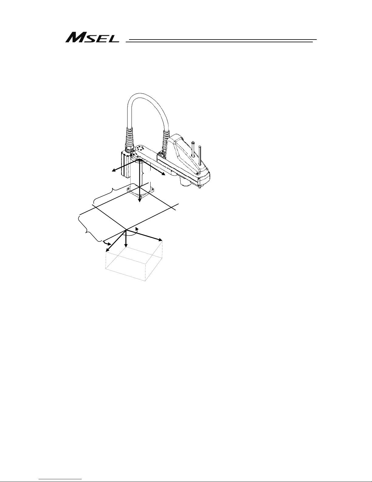
(7) Horizontal Articulated (SCARA) Robot ⋅ ⋅ IXP Type Dedicated
There are three types of coordinate systems, base coordinate system, work coordinate system
and tool coordinate system.
[Base Coordinate System (= Work Coordinate System No. 0)]
It is the 3-dimensional orthogonal coordinates + rotation axis coordinate (dedicated for 4-axis
type) defined in the robot at delivery.
Work coordinate system No. 0 (work coordinate system offset 0) = Base coordinate system.
The origin of X and Y axes is the center of the base (rotation center of the 1
st
arm).
The origin of Z axis is the upper end of the effective stroke on the Z axis.
The origin of R axis is the position that the D-cut surface faces –Xb direction.
X axis of base coordinate system is described as Xb, Y axis as Yb, Z axis as Zb and R axis as
Rb.
Top view of J2 axis
Rb
(For 4
-axis specification)
Xb
Zb
Yb
+Zb
Stroke
Z-axis position
Zb=0
-Zb
-Xb
+Rb
-Rb
Center of tool
attachment face
D-cut surface on
r
otational axis
Page 28
20
[Work Coordinate System]
It is 32 types of the 3-dimensional orthogonal coordinates + rotation axis coordinate defined by
the offset to base coordinate system. Work coordinate system No. 0 is reserved as base
coordinates (= work coordinate system offset = 0) by the system.
Xb
Zb
Yb
Zofwn
Xwn
Zwn
Ywn
Yofwn
Rofwn
Rwn
Xofwn
Xofwn : X Work coordinate system offset
Yofwn : Y Work coordinate system offset
Zofwn : Z Work coordinate system offset
Rofwn : R Work coordinate system offset
Xwn : Work coordinate system X axis
Ywn : Work coordinate system Y axis
Zwn : Work coordinate system Z axis
Rwn : Work coordinate system R axis
(n is the work coordinate system number)
Page 29

21
[Tool Coordinate System]
It is 128 types of the 3-dimensional orthogonal coordinates + rotation axis coordinate defined
by the tool (such as hand) dimension (offset) attached to the tool attachment surface. Work
coordinate system No. 0 is reserved as offset 0 of tool coordinates by the system.
If the defined tool coordinate system number is selected, the tool tip is used as the reach point
at the positioning, not the center of the tool attachment surface.
Select the defined tool coordinate system and operate the R axis with JOG operation, and
such movement as shown in the figure below can be performed.
Xoftn : X Tool coordinate system offset
Yoftn : Y Tool coordinate system offset
Zoftn : Z Tool coordinate system offset
Roftn : R Tool coordinate system offset
Xtn : Tool coordinate system X axis
Ytn : Tool coordinate system Y axis
Ztn : Tool coordinate system Z axis
Rtn : Tool coordinate system R axis
(n is the toof coordinate system number)
Tool
R-axis
Tool ti
p
Page 30

22
Page 31

Chapter 1 Specications Check
23
Chapter 1 Specifications Check
1.1 Product Check
The standard configuration of this product is comprised of the following parts.
If you find any faulty or missing parts, contact your local IAI distributor.
1.1.1 Parts (Excluding Options)
No. Part Name Model
Quantity
1 Controller Main Body
Refer to “How to read the model plate”, “How to read the
model”. [Refer to 1.1.4 or 1.1.5.]
1
Accessories
2 System I/O Plug DFMC1.5/6-ST-3.5 (Supplier: PHOENIX CONTACT) 1
3 AC Power Plug
MSTB2.5/3-STF-5.08 (SK: N-PE)
(Supplier: PHOENIX CONTACT)
1
4
Motor Drive Power
Line Connector
FKIC2.5HC/2-ST-5.08 (Supplier: PHOENIX CONTACT) 1
5 Dummy Plug DP-4S (Enclosed in PG, PGF or PGX) 1
6 I/O Flat Cable
CB-PAC-PIO□□□ □□□ shows the cable length
(Example) □□□ : 020 = 2m
(In common for both standard I/O and extension I/O (PIO
type))
1 or 2
(for number of
mounted PIO)
Model CC: MSTB2.5/5-STF-5.08AU
(Supplier: PHOENIX CONTACT)
7 CC-Link Connector
Model CC2: TMSTBP2.5/5-STF-5.08 AUBD-FG
(Supplier: PHOENIX CONTACT)
1
Model DV: MSTB2.5/5-STF-5.08AUM
(Supplier: PHOENIX CONTACT)
8 DeviceNet Connector
Model DV2: TMSTBP2.5/5-STF-5.08 AUM
(Supplier: PHOENIX CONTACT)
1
9 First Step Guide 1
10
Instruction Manual
(DVD)
1
11 Safety Guide 1
1.1.2 Teaching Tool (Optional)
A teaching tool such as PC software is necessary when performing the setup for creating a
program, position setting and parameter setting, etc. that can only be done on the teaching tool.
Please prepare either of the following teaching tools.
No. Part Name Model
1
PC Software (with RS232C Cable + Connector Conversion Cable ・ with Emergency
Stop Box)
IA-101-X-MW-JS
2 PC Software (with USB Cable (CB-SEL-USB030) + Dummy Plug (DP-4S)) IA-101-X-USBS
3 Teaching Pendant TB-02
4 Teaching Pendant TB-01
Page 32

Chapter 1 Specications Check
24
1.1.3 Instruction Manuals Related to this Product, which are Contained in the
Instruction Manual (DVD).
No. Name Manual No.
1 SEL Language Programming Manual ME0224
2
PC Software
IA-101-X-MW-JS/IA-101-X-USBS Instruction Manual
ME0154
3 Touch Panel Teaching TB-01/TB-01D Instruction Manual ME0325
4 Touch Panel Teaching TB-02 Instruction Manual ME0356
5 DeviceNet Instruction Manual ME0124
6 CC-Link Instruction Manual ME0123
7 PROFIBUS-DP Instruction Manual ME0153
8 Ethernet Instruction Manual ME0140
9 EtherNet/IP Instruction Manual ME0308
10 EtherCAT Instruction Manual ME0309
11 PROFINET IO Instruction Manual ME0361
1.1.4 How to Read the Model Plate
1.1.5 How to Read the Model
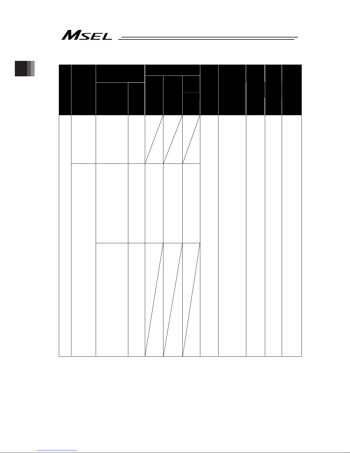
[1-1] Single-Axis and Cartesian Type Controllers
Connected Axis Content
Series
Controller
type
Axis
No.
Pulse motor
type
Encoder
type
(Note 3)
Optional
Standard
I/O content
Extension I/O content
I/O
cable length
Power
supply
voltage
Absolute
Battery
(Note 2)
Mount
specification
WAI
(Note 3)
(battery-
less
absolute/
incremental)
Not
specified
HS
(Note 1)
(homeposition
check
sensor)
B
(brake)
Not specified
(battery-
less absolute/
incremental)
20P
(20 frame)
20SP
(20 frame)
28P
(28 frame)
28SP
(28 frame)
35P
(35 frame)
42P
(42 frame)
42SP
(42 frame)
56P
(56 frame)
SA
(Note 2, Note 3)
(simple
absolute)
B
(brake)
MSEL
PC
(standard
type)
PG
*1
(safety
category
compliant
type)
1
(
1 axis
)
2
(2 axes
)
3
(
3 axes
)
4
(
4 axes
)
WUS
(Note 4)
WUM
NP
(NPN PIO
connect)
PN
(PNP PIO
connect)
E : Not for use
DV : (DeviceNet
connect)
CC : (
CC-Link connect
)
PR : (PROFIBUS-DP
connect)
EP : (EtherNet/IP
connect)
NP : (
NPN PIO connect
)
EC : (EtherCAT
connect)
PRT : (PROFINET IO
connect)
DV2 : (DeviceNet
connect
Connector for
multidrop
enclosed)
CC2 : (CC-Link connect
Connector for
multidrop
enclosed)
SE1 : (RS232C
connect)
SE2 : (RS485 connect)
IA : (IA net connect)
0
(no cable)
2
(2m:
standard)
3
(3m)
5
(5m)
4
(100 AC
to 230V
input)
ABB
(Note 2)
Simple
absolute
(with battery
box)
ABBN
(Note2)
Simple
absolute
(without
battery box)
Not specified
(screw
mounting)
DN
(DIN
rail mounting)
*1 Safety Category Complied Type: This is a type that enables to construct a safety protection circuit
Note 1 It is available to select when the actuator is “Incremental Type”.
Note 2 When “Simple Absolute Type” has been selected, select “ABB” or “ABBN”.
Note 3 “Battery-less Absolute / Incremental Type” and “Simple Absolute Type” cannot be used together.
Note 4 WUS and WUM occupy two axes. It is not necessary to describe an encoder type or option.
Model
Serial numbe
r
MODEL MSEL-PCX4-3N4515WAI-56PWAI-NP-CC-2-4-DN-**
SERIAL No.200198765 MADE IN JAPAN
Page 33

Chapter 1 Specications Check
25
[1-2] Single-Axis and Cartesian Type Controllers (High-Thrust Specification)
Connected Axis Content
Series
Controller
type
Axis
No.
Pulse motor
type
Encoder
type
(Note 3)
Optional
Standard
I/O content
Extension I/O content
I/O
cable length
Power
supply
voltage
Absolute
Battery
(Note 2)
Mount
specification
WAI
(Note 4)
(battery-less
absolute/
incremental)
Not
specified
HS
(Note1)
(
home-
position
check
sensor
)
B
(
brake
)
Not specified
(battery-less
absolute/
incremental)
MSEL
PCF
(high-thrust
type)
PGF
*1
(high-thrust
safety
category
compliant
type)
1
(1 axis)
2
(2 axis)
3
(3 axis)
4
(4 axis)
1
st
and 2nd
axes
56SP
(56 frame)
60P
(60 frame)
86P
(86 frame)
2
nd
to 4th
axes
20P
(20 frame)
20SP
(20 frame)
28P
(28 frame)
28SP
(28 frame)
35P
(35 frame)
42P
(42 frame)
42SP
(42 frame)
56P
(56 frame)
(Note 3, Note 5)
SA
(Note2 to Note 4)
(simple
absolute)
B
(
brake
)
NP
(NPN PIO
connect)
PN
(PNP PIO
connect)
E : Not for use
DV : (DeviceNet
connect)
CC : (CC-Link
connect)
PR : (PROFIBUS-DP
connect)
EP : (EtherNet/IP
connect)
NP : (NPN PIO
connect)
EC : (EtherCAT
connect)
PRT : (PROFINET-IO
connect)
DV2 : (DeviceNet
connect
Connector for
multidrop
enclosed)
CC2 : (CC-Link connect
Connector for
multidrop
enclosed)
SE1 : (RS232C
connect)
SE2 : (RS485 connect)
IA : (IA net connect)
0
(no cable)
2
(2m:
standard)
3
(3m)
5
(5m)
4
(AC100
to 230V
input)
ABB
(Note 2)
Simple
absolute
(with battery
box)
ABBN
(Note 2)
Simple
absolute
(without
battery box)
Not specified
(screw
mounting)
DN
(DIN rail
mounting)
*1 Safety Category Complied Type: This is a type that enables to construct a safety protection circuit
Note 1 It is available to select when the actuator is “Incremental Type”.
Note 2 When “Simple Absolute Type” has been selected, select “ABB” or “ABBN”.
Note 3 Simple Absolute cannot be selected in the high-thrust type (56SP, 60P and 86P motors).
Note 4 “Battery-less Absolute/Incremental Type” and “Simple Absolute Type” cannot be used together on
the 3
rd
and 4th axes. 2nd, 3rd and 4th axes can be existed together.
Note 5 For the 2
nd
axis, the type can be selected at the order from the standard type (20P to 56P motor)
and the high-thrust type (56SP, 60P or 86P motor).
(Driver board is different.)
Page 34
Chapter 1 Specications Check
26
[2] SCARA Robot Controller
Added axis content
Power-con SCARA model
Series
Controller
type
Following type
symbols come in □
N : Standard
C : Cleanroom
W : Dust Proof/Splash
Proof
Optional
Pulse
motor type
Encoder
type
Optional
Standard
I/O content
Extension I/O
content
I/O
cable
length
Power
supply
voltage
Mount
specification
PCX3
(3 axes
standard
type)
PGX3
*1
(3 axes safety
category
compliant
type)
(3 axes type)
3N1808WAI
3N2508WAI
3�3515WAI
3�4515WAI
3�5520WAI
3�6520WAI
B
(Note2)
(Brake)
(3 axes type)
3N1808WAI
3N2508WAI
3�3515WAI
3�4515WAI
3�5520WAI
3�6520WAI
B
(Note2)
(Brake)
20P
(20 frame)
20SP
(20 frame)
28P
(28 frame)
28SP
(28 frame)
35P
(35 frame)
42P
(42 frame)
42SP
(42 frame)
56P
(56 frame)
WAI
(Battery-
less
absolute/
Incremental)
Not
specified
HS
(Note 1)
(home-
position
check
sensor)
B
(brake)
MSEL
PCX4
(4 axes
standard
type)
PGX4
*1
(4 axes safety
category
compliant
type)
(4 axes type)
4N1808WAI
4N2508WAI
4�3515WAI
4�4515WAI
4�5520WAI
4�6520WAI
(3 axes type+
Gripper mounted)
3N1808GMWAI
3N2508GMWAI
3N3515GMWAI
3N4515GMWAI
3N3510GLWAI
3N4510GLWAI
3N5515GLWAI
3N6515GLWAI
3N5515GWWAI
3N6515GWWAI
B
(Note2)
(Brake)
NP
(NPN PIO
connect)
PN
(PNP PIO
connect)
E : (not for
use)
DV : (DeviceNet
connect)
CC : (
CC-Link
connect
)
PR :
(PROFIBUS-DP
connect)
EP :
(EtherNet/IP
connect)
NP : (
NPN PIO
connect
)
EC : (EtherCAT
connect)
PRT : (PROFINET
IO connect)
DV2 : (DeviceNet
connect
Connector
for
multidrop
enclosed)
CC2 : (CC-Link
connect
Connector
for
multidrop
enclosed)
SE1 : (RS232C
connect)
SE2 : (RS485
connect)
IA : (IA net
connect)
0
(No
cable)
2
(2m:
standard)
3
(3m)
5
(5m)
4
(100 AC
to 230V
input)
Not
specified
(Screw
mounting)
DN
(DIN
Rail mounting)
*1 Safety Category Complied Type: This is a type that enables to construct a safety protection circuit
Note 1 It is available to select when the actuator is “Incremental Type”.
Note 2
When SCARA Robot is with the arm length 550mm or 650mm, it can be selected for Z-axis.
Page 35

Chapter 1 Specications Check
27
1.2 Basic Specifications
Specification Item
Number of Controlled Axes 1 axis to 4 axes (Total of RC axis or SCARA axis + RC axis is four axes max.)
Power Supply Voltage Single-phase 100V AC to 230V±10%
Power Current (typ value) 2.9A (100V AC), 1.4A (200V AC), 1.2A (230V)
Power Supply Frequency 50Hz/60Hz±5%
Rush Current (typ value)
(Note 1)
15A(100V AC), 30A(200V AC)
(Ambient Temp. 25degC, Measurement in one time of turn-ON: when no
repeating of ON/OFF)
Leakage Current
(Note 2)
0.75mA or less
Transient Power Cutoff Durability 20ms or more
Heat Generation 40W (100V AC), 35.2W (200V AC), 30.4W (230V AC)
PIO Power Supply
(Note 3)
DC24V±10% (Supplied from external equipment)
Motor Control System Weak field-magnet vector control
Applicable Encoder
(The resolution differs depending on the
actuator type)
Battery-less absolute encoder or Incremental encoder
resolution 800pulse/rev or 8192pulse/rev
Actuator Cable Length MAX. 20m (when simple absolute type is used Max.10m)
Serial Communication Interface (SIO port
or USB port)
Teaching tool dedicated connector (SIO ports and USB ports excluded)
(XSEL serial communication protocol (Format B))
(Standard / extension) PIO
24V DC general-purposed signal I/O (NPN / PNP selection)
Input 32 points max., output 32 points max. (Total of standard and extension)
Cable length MAX.10m
External
Interface
(Extension dedicated) Fieldbus
DeviceNet, CC-Link, PROFIBUS-DP, EtherNet/IP
(Note 4)
, EtherCAT,
PROFINET IO, RS232C, RS485
Data Setting and Input PC software or teaching pendant
Program Specification SEL Language
Max. Number of Program Steps 9999 steps
Max. Number of Positions 30000 position
Max. Number of Programs 255 program
Max. Number of Multitask Programs 16 program
Data Retention Memory Flash ROM and FeRAM
Clock Function
Retaining time after power turned OFF: approximately 10 days
Time for battery charge after the clock data is lost: approximately 100 hours
System I/O Emergency stop input, safety gate input
Drive-source cutoff method
Contact point for semiconductor (connect externally such as driving source cutoff
relay when required to comply with safety categories for PG/PGF/PGX types)
Emergency-stop input
b contact (normally closed) Input (internal power supply)
Safety Circuit
Configuration
Enable input
b contact (normally closed) Input (internal power supply)
Protective Functions
Motor over current, overload, encoder open circuit detection, soft limit over,
system abnormality, battery abnormality
Absolute Battery (when simple absolute
type is used)
AB-7
Protection Function Against Electric
Shock
Class I In case grounding conducted on ground terminal in addition to basic
insulation for electric shock proof.
Overvoltage Category Category II Voltage durability 2500V at less than 300V AC for input rating
Insulation Resistance
10MΩ or more (between power terminal and I/O terminal and also all external
terminals and case at the power supply of DC500V)
Insulation Strength
1500V AC for 1 min (between primary and PE)
3000V AC for 1 min (between primary and secondary)
Protection Conduction 10A 1.0V or less (for 10sec)
Cooling Method Forced air-cooling
Surrounding air temperature 0 to +40°C
Surrounding humidity
85% RH or less (non-condensing)
Surrounding environment
(Refer to the Item for the 1.6 Installation Environment).
Surrounding storage
temperature
-20 to 70C (Note) 0 to 40C for absolute battery
Surrounding storage humidity
85% RH or less (non-condensing)
Maximum operation height 1000m
Vibration resistance
10 to 57 Hz in XYZ directions Swing width: 0.075mm
57 to 150Hz Acceleration: 9.8m/s
2
Protection class IP20
Environment
Pollution degree Pollution degree 2
External Dimensions [Refer to the 1.3 External Dimensions]
Mass
Approx. 1.4kg
Page 36

Chapter 1 Specications Check
28
Note 1 Rush current at the power connection continues for 5 msec. Note that the value of in-rush current
differs depending on the impedance of the power supply line.
Note 2 Leak current varies depending on the capacity of connected motor, cable length and the surrounding
environment. Measure the leak current at the point where a ground fault circuit interrupter is to be
installed when leakage protection is conducted.
Regarding the leakage breaker, it is necessary to have a clear purpose for selection such as a fire
protection or protection of human body.
Note 3 Power supply is not necessary if PIO is not to be used.
Note 4 EtherNet/IP can also communicate (teletype procedure communication) with EtherNet.
1.2.1 Selection of the Circuit Breaker
For the selection of the circuit breaker, perform it according to the following items.
Select the breaker that does not trip with the rush current. (Refer to the Operation
Characteristic Curve described in the catalogue of each manufacturer.)
For the rated breaking current, select the current value which can break the current even
when a short circuit occurs.
Rated Interrupting Current > Short Circuit Current = Power Source Current [Refer to 1.2
Basic Specifications]
Consider margin for the rated current on the circuit breaker.
Circuit Breaker Rated Current > Power Source Current [A] × Safety Margin (Reference 1.2 to 1.4)
1.2.2 Selection of the Leakage Breaker
Regarding the leakage breaker, it is necessary to have a clear purpose for selection such
as a fire protection or protection of human body.
Leak current varies depending on the capacity of connected motor, cable length and the
surrounding environment. Measure the leak current at the point where a ground fault
circuit interrupter is to be installed when leakage protection is conducted.
Page 37

Chapter 1 Specications Check
29
116
185
4-4.5
130
19
5
(10.9)
5
.
9
125
(75mm from DIN Rail center)
3
3
1.3 External Dimensions
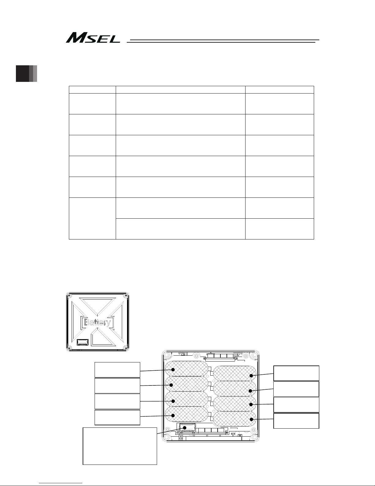
1) Main Body
2) Absolute Battery Box (Simple Absolute Type)
(59mm from DIN Rail center)
5
111
123
98
10.5
5
5
108
115
(4)
4
5
Page 38

Chapter 1 Specications Check
30
1.4 Interfaces
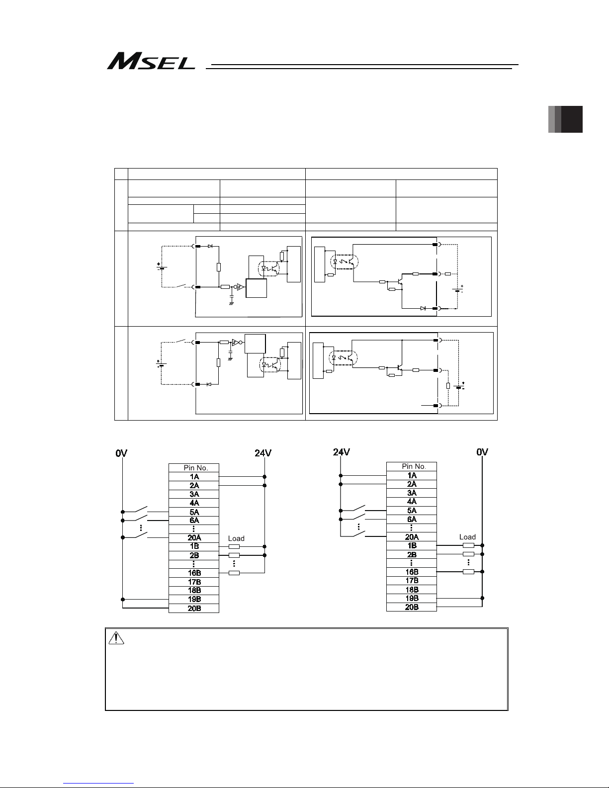
Standard I/O can be equipped with PIO (NPN or PNP).
1.4.1 Standard I/O
Input Output
Input Voltage 24V DC ±10%
Load Voltage
24V DC ±10%
Input Current 7mA / 1 Circuit
ON
Min. 16V DC
ON/OFF
Voltage
OFF
Max. 5V DC
Load Current 100mA / 1 Circuit, 400mA / 8 Port
*1
Specification
Insulation Type
Photocoupler Insulation
Insulation Type
Photocoupler Insulation
NPN PNP
Note 1 The total of lead current reaches max. 400mA every 8 ports from output port No. 300.
NPN specification PNP specification
Caution:
If a non-contact circuit is connected externally, malfunction may result from
leakage current. Use a circuit in which leakage current in a OFF state does not
exceed 1mA.
At the default settings, the system recognizes the ON/OFF durations of input
signals if they are continuous approx. 4 msec or longer. The ON/OFF duration
settings can also be changed using I/O parameter No. 20 (input filtering
frequency).
MSEL
560Ω
3.3kΩ
Input Terminal
Input
Terminal
560Ω
Output
Terminal
10Ω
Load
Output
Terminal
10Ω
Load
MSEL
3.3kΩ
External
Power
Source
24V DC
±10%
External
Power
Source
24V DC
±10%
External
Power
Source
24V DC
±10%
External
Power
Source
24V DC
±10%
MSEL
MSEL
Internal circuit
Internal circuit
Internal circuit
Internal circuit
Page 39
Chapter 1 Specications Check
31
1.4.2 Extension I/O
For extension I/O, selection can be made from PIO (NPN or PNP) and six types of fieldbus
(CC-Link, DeviceNet, FROFIBUS-DP, EtherNet/IP, EtherCAT or PROFINET-IO) to be equipped
with.
[1] PIO Interfaces
Input Output
Input Voltage 24V DC ±10%
Load Voltage
24V DC ±10%
Input Current 4mA / 1 Circuit
ON
Min. 18V DC
ON/OFF
Voltage
OFF
Max. 6V DC
Load Current 50mA / 1 Circuit
Specificatio
Insulation Type
Photocoupler Insulation
Insulation Type
Photocoupler Insulation
NPN PNP
NPN type PNP type
Caution:
If a non-contact circuit is connected externally, malfunction may result from
leakage current. Use a circuit in which leakage current in a OFF state does not
exceed 1mA.
At the default settings, the system recognizes the ON/OFF durations of input
signals if they are continuous approx. 4 msec or longer. The ON/OFF duration
settings can also be changed using I/O parameter No. 20 (input filtering
frequency).
MSEL
5.6kΩ
Input Terminal
logic
circuit
Input
Terminal
5.6kΩ
logic
circuit
Output
Terminal
15Ω
Load
Output
Terminal
15Ω
Load
MSEL
External
Power
Source
24V DC
±10%
External
Power
Source
24V DC
±10%
External
Power
Source
24V DC
±10%
External
Power
Source
24V DC
±10%
MSEL
MSEL
Internal circuit
Internal circuit
Internal circuit
Internal circuit
Page 40
Chapter 1 Specications Check
32
[2] Fieldbus
Following fieldbus can be selected. For details, refer to each instruction manual provided
separately.
Type Overview Details
DeviceNet DeviceNet Field Network Board
This board communicates the I/O data as the
remote I/O terminal.
Refer to the separate.
(ME0124)
CC-Link CC-Link Field Network Board
This board communicates the I/O data as the
Ver1.10 remote device station.
Refer to the separate.
(ME0123)
PROFIBUS-DP PROFIBUS-DP Field Network Board
This board communicates the I/O data as the
slave station.
Refer to the separate.
(ME0153)
PROFINET-IO PROFINET-IO Field Network Board
This board communicates the I/O data as the
slave station.
Refer to the separate.
(ME0361)
EtherCAT EtherCAT Field Network Board
This board communicates the I/O data as the
slave station.
Refer to the separate.
(ME0309)
EtherNet/IP Network Connecting Communication
Board
I/O data communication also can be executed.
Refer to the separate.
(ME0308)
EtherNet/IP
Communication is established with Ethernet
Communication (teletype procedure
communication).
Refer to the separate.
(ME0140)
1.5 Absolute Battery Box (to be Connected for Simple Absolute Type)
The dedicated absolute battery box is to be used for simple absolute type.
The battery is to be mounted only to the absolute type axes in the places for 1st to 4th axes in
the figure below.
Connection to MSEL controller is to be conducted with a dedicated cable (CB-MSEL-AB005).
(Note) Cable length 0.5m
Front View with Cover on
AX3
AX7
AX1
AX4AX5AX6AX7
AX3AX2 AX1AX0
AX4
AX6
AX0
AX2
AX5
Not to use
Not to use
1
s
t
battery
(Axis No.0)
3
r
d
battery
(Axis No.2)
Connector for connection to
MSEL
(Note) Do not attempt to plug in
or take off the cable with
force in the tilted direction
to the connector.
Front View after Cover Removed
Not to use
Not to use
2
n
d
battery
(Axis No.1)
4th battery
(Axis No.3)
Page 41

Chapter 1 Specications Check
33
1.6 Installation and Storage Environment
This product is capable for use in the environment of pollution degree 2*1 or equivalent.
*1 Pollution Degree 2: Environment that may cause non-conductive pollution or transient
conductive pollution by frost (IEC60664-1).
[1] Installation Environment
Do not use this product in the following environment:
Location where the surrounding air temperature exceeds the range of 0 to 40°C
Location where condensation occurs due to abrupt temperature changes
Location where relative humidity exceeds 85%RH
Location exposed to corrosive gases or combustible gases
Location exposed to significant amount of dust, salt or iron powder
Location subject to direct vibration or impact
Location exposed to direct sunlight
Location where the product may come in contact with water, oil or chemical droplets
Environment that blocks the air vent [1.7 Noise Prevention and the Installation]
When using the product in any of the locations specified below, provide a sufficient shield.
Location subject to electrostatic noise
Location where high electrical or magnetic field is present
Location with the mains or power lines passing nearby
[2] Storage and Preservation Environment
Storage and preservation environment follows the installation environment. However, the
ambient temperature should be from -20 to 70°C (0 to 40°C for absolute battery) and the
relative humidity to be 85%RH at maximum. Especially in a long-term storage, consider
to avoid condensation of surrounding air.
Unless specially specified, moisture absorbency protection is not included in the package
when the machine is delivered. In the case that the machine is to be stored and
preserved in an environment where dew condensation is anticipated, take the
condensation preventive measures from outside of the entire package, or directly after
opening the package.
Page 42

Chapter 1 Specications Check
34
1.7 Noise Prevention and the Installation
(1) Protective Grounding
For grounding, conduct a protective grounding using a strand or annealed copper wire with the
diameter 1.25mm
2
(AWG16) or more.
Controller
Other
equipment
Controller
Other
equipment
Other
equipment
(2) Precautions Regarding Wiring Method
1) Use a twisted cable for connection to the power supply.
2) To reduce the interference to each other, have the I/O line, communication and encoder
lines, power and driving supply lines separate from each other.
(3) Noise Sources and Elimination
Carry out noise elimination measures for power devices
on the same power path and in the same equipment.
The following are examples of measures to eliminate
noise sources:
1) AC solenoid valves, magnet switches and relays
[Measure] Install a Surge Absorber parallel with
the coil.
2) DC solenoid valves, magnet switches and relays
[Measure] Install a diode parallel with the coil.
Use a DC relay with a built-in diode.
Do not share the ground wire with or connect
to other equipment. Ground each controller.
AC power supply
Protective grounding (PE)
Strand or annealed
copper wire
[1.25mm
2
(AWG16)]
0
V
R
C
+24V
0V +24V
Surge Absorber
Relay
coil
Relay coil
Page 43

Chapter 1 Specications Check
35
(4) Heat Radiation and Installation
Conuct design and manufacture in consideration of the control box size, controller layout and
cooling in such a way that the temperature around the controller will be 40C or less.
In case of layout with multiple controllers aligned vertically, consider not to have exhaust of
bottom side controllers flow directly to the inlet of the upper controllers.
Especially around the battery, the performance may drop in both low and high temperature.
Keep it in ambient temperature as much as possible. (Approximately 20C is the
recommended temperature.)
Direction Vertical installation (Exhaust on top)
Installation
Method Screw attachment or DIN rail attachment
Ceiling
100mm or more
300mm
or more
200mm
or more
50mm or more
30mm or more
A
ir flow
A
ir flow
150mm or more
Air outlet
Air inlet
Air flow
Fan
Page 44

Chapter 1 Specications Check
36
Page 45

Chapter 2 Wiring
37
Chapter 2 Wiring
2.1 Wiring (Example connection of devices) Diagram
[1] PC/PG/PCF/PGF Controller (Single and Cartesian Axes Type)
[2] PCX/PGX Controller (IXP Series SCARA Robot Control Type)
A
ctuator (IXP)
A
ctuator
(RCP
series)
Power Supply
(Single-phase
100~230V AC)
Contact for Cutoff
(Note 1)
(when supplying / cutting off power source externally)
Host Device
(Note
1
)
PIO
Fieldbus
Emergency Stop
(Note 1)
Safety Circuit
(Note 1)
(Enable)
Teaching Tool (Option)
A
ctuator (RCP)
A
bsolute Battery Box
Contact for Cutoff
(Note 1)
(when supplying / cutting off power source externally)
Host Device
(Note
1
)
PIO
Emergency Stop
(Note 1)
Safety Circuit
(Note 1)
(Enable)
Teaching Tool (Option)
Fieldbus
Power Supply
(Single-phase
100~230V AC)
Note 1 Please prepare separately.
Note 1 Please prepare separately.
Page 46

Chapter 2 Wiring
38
Caution: Make sure to turn the power to the controller OFF when inserting or removing
the connector that connects the PC software or teaching pendant to the
controller.
Inserting or removing the connector while the power is turned ON causes a
controller failure.
Caution: A number is shown on the cable for SCARA Robot.
Connect it according to the controller connector number.
For the actuator regarded as that for single-axis robot, the connector Nos. are
not indicated.
In such case, give a number to each connector to avoid any mistake.
If the cable is not correctly connected, it might cause a damage to or
malfunction of the motor or PCB board.
Page 47

Chapter 2 Wiring
39
2.2 Circuit Diagram (Example)
2.2.1 Power Supply Circuit
Caution: Leakage current varies depending on the capacity of the motor to be connected,
cable length and surrounding environment. Therefore, when protective
measures from the leakage are taken, measure the leakage current at the
locations where the leakage breaker is installed.
Regarding the leakage breaker, it is necessary to have a clear purpose for
selection such as a fire protection or protection of human body.
L N
MSEL
AC Power Supply Input Connector
Circuit Breaker
Leakage Breaker
L
N
PE
Protective Grounding
Page 48
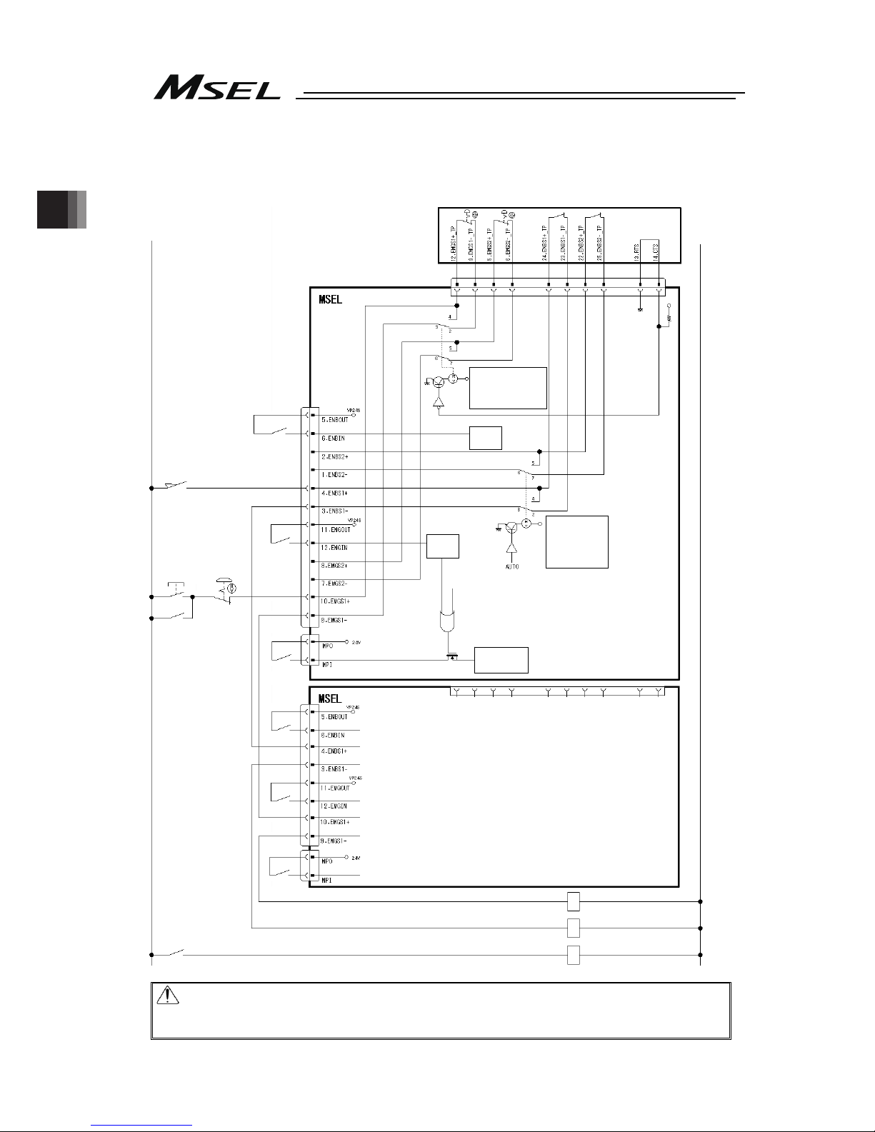
Chapter 2 Wiring
40
2.2.2 Emergency Stop and Enable Circuit (PC/PCF/PCX Type)
The following diagram shows the case when the teaching pendants emergency stop switch is
reflected on the machine’s emergency stop circuit design.
Caution: For PC/PCF/PCX type, the dead man’s switch on the teaching pendant is valid
in MANU Mode. The Emergency Stop Switch is always enabled regardless of
MANU/AUTO mode.
0V
Teaching pendant
24V
System I/O
Connector
Motor driving power supply
line connector
SIO Connector
CR1
CR2
Safety gate
CR1
MC1
Emergency
stop reset
switch
CR2
MC1
Emergency
stop switch
CR1
CR2
MC1CR1
Teaching pendant connected
2-3 and 6-7 short-circuited
Teaching pendant disconnected
3-4 and 5-6 short-circuited
MANU mode
2-3 and 6-7
short-circuited
AUTO mode
3-4 and 5-6
short-circuited
(Note 1)
(Note 2)
(Note 4)
(Note 3)
(Note 4)
(Note 5)
(Note 5)
Motor driving
circuit
ENB
Status
detection
EMB
Status
detection
Page 49

Chapter 2 Wiring
41
Note 1: EMGS1+ and EMGS1- make short-circuit inside the controller if a teaching pendant is
not connected.
Note 2: In AUTO mode, short-circuit is made between ENBS1+ and ENBS1- inside the
controller.
Note 3: When it is necessary to cut off the motor power source externally for such reason as
to comply with safety category, connect a contact such as a connector on the wire
between MPO and MPI terminals on the motor driving power line connector.
Shown below is table for the power specifications between MPO and MPI terminals.
Specifications
Voltage 24V DC (Built-in power supply)
Type PC/PCX
PCF
Numbers in brackets ( ) are in
case of high-thrust axis
1-axis type 2A 1.5A
2-axis type 4A 3.5A (3.0A)
3-axis type 6A 5.5A (5.0A)
Rated current
4-axis type 8A 7.5A (7.0A)
1-axis type 4A 6A
2-axis type 8A 10A (12A)
3-axis type 12A 14A (16A)
Maximum current
4-axis type 16A 18A (20A)
Note 4: The ratings for the emergency stop signal (EMGIN) that turns ON/OFF at the contact
CR1 and the enable signal (ENBIN) that turns on/off at the contact CR2 are 24V DC
and 10mA or less.
The emergency stop output (EMGOUT) and the enable output (ENBOUT) are
available for connection to 30V DC and 0.5A or less.
Note 5: For CR1 and CR2, select the one with coil current 0.1A or less.
Page 50
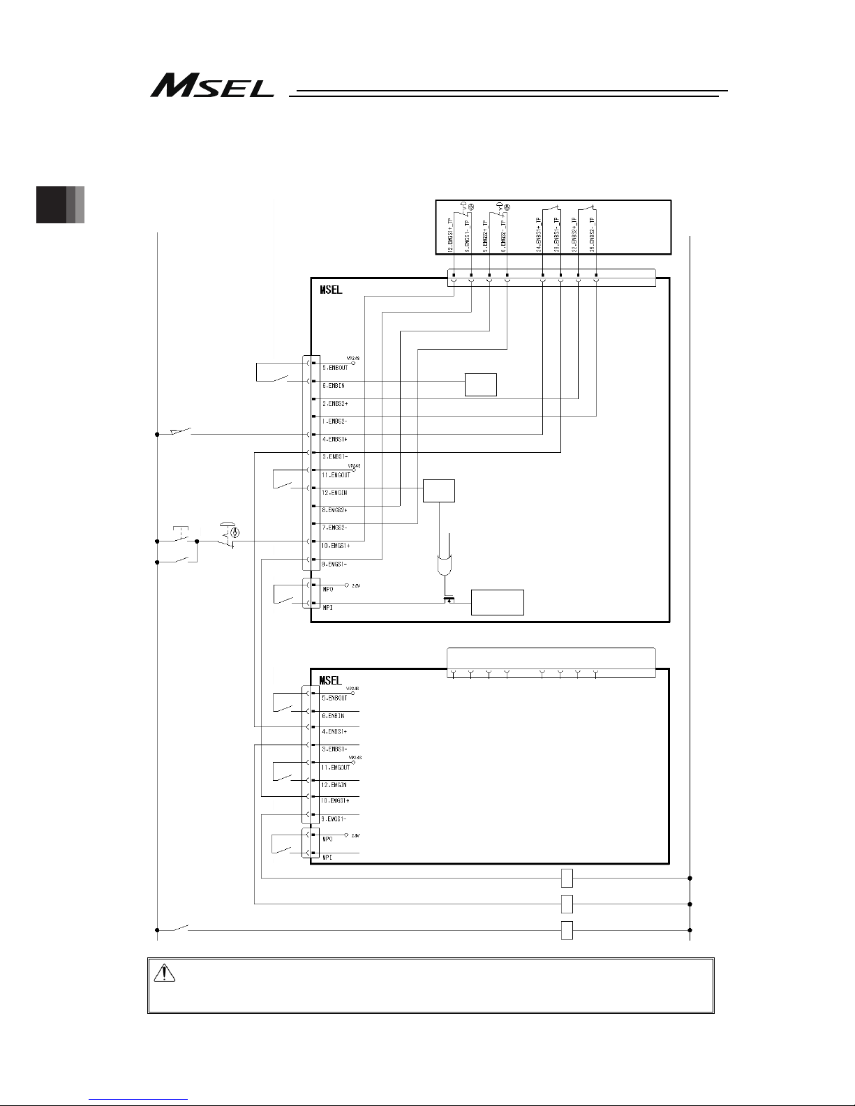
Chapter 2 Wiring
42
2.2.3 Emergency Stop and Enable Circuit (PG/PGF/PGX Type)
The following diagram shows the case when the teaching pendants emergency stop switch is
reflected on the machine’s emergency stop circuit design.
Caution: For PG/PGF/PGX type, the emergency stop switch and the dead man’s switch
on the teaching pendant are always valid. Apply the dummy plug (DP-4S) if the
teaching pendant is not connected.
0V
Teaching pendant
24V
System I/O
Connector
SIO
Connector
CR1
CR2
Safety gate
CR1
MC1
Emergency
stop reset
switch
CR2
MC1
Emergency
stop switch
CR1
CR2
MC1
CR1
Dummy plug (DP-4S)
(Note 1)
(Note 2)
(Note 3)
(Note 2)
(Note 3)
Motor driving power supply
line connector
Motor driving
circuit
ENB
Status
detection
EMB
Status
detection
Page 51

Chapter 2 Wiring
43
Note 1: When it is necessary to cut off the motor power source externally for such reason as
to comply with safety category, connect a contact such as a connector on the wire
between MPO and MPI terminals on the motor driving power line connector.
Shown below is table for the power specifications between MPO and MPI terminals.
Specifications
Voltage 24V DC (Built-in power supply)
Type PG/PGX
PGF
Numbers in brackets ( ) are in
case of high-thrust axis
1-axis type 2A 1.5A
2-axis type 4A 3.5A (3.0A)
3-axis type 6A 5.5A (5.0A)
Rated current
4-axis type 8A 7.5A (7.0A)
1-axis type 4A 6A
2-axis type 8A 10A (12A)
3-axis type 12A 14A (16A)
Maximum current
4-axis type 16A 18A (20A)
Note 2: The ratings for the emergency stop signal (EMGIN) that turns on/off at the contact
CR1 and the enable signal (ENBIN) that turns ON/OFF at the contact CR2 are 24V
DC and 10mA or less.
The emergency stop output (EMGOUT) and the enable output (ENBOUT) are
available for connection to 30V DC and 0.5A or less.
Note 3: For CR1 and CR2, select the one with coil current 0.1A or less.
Page 52
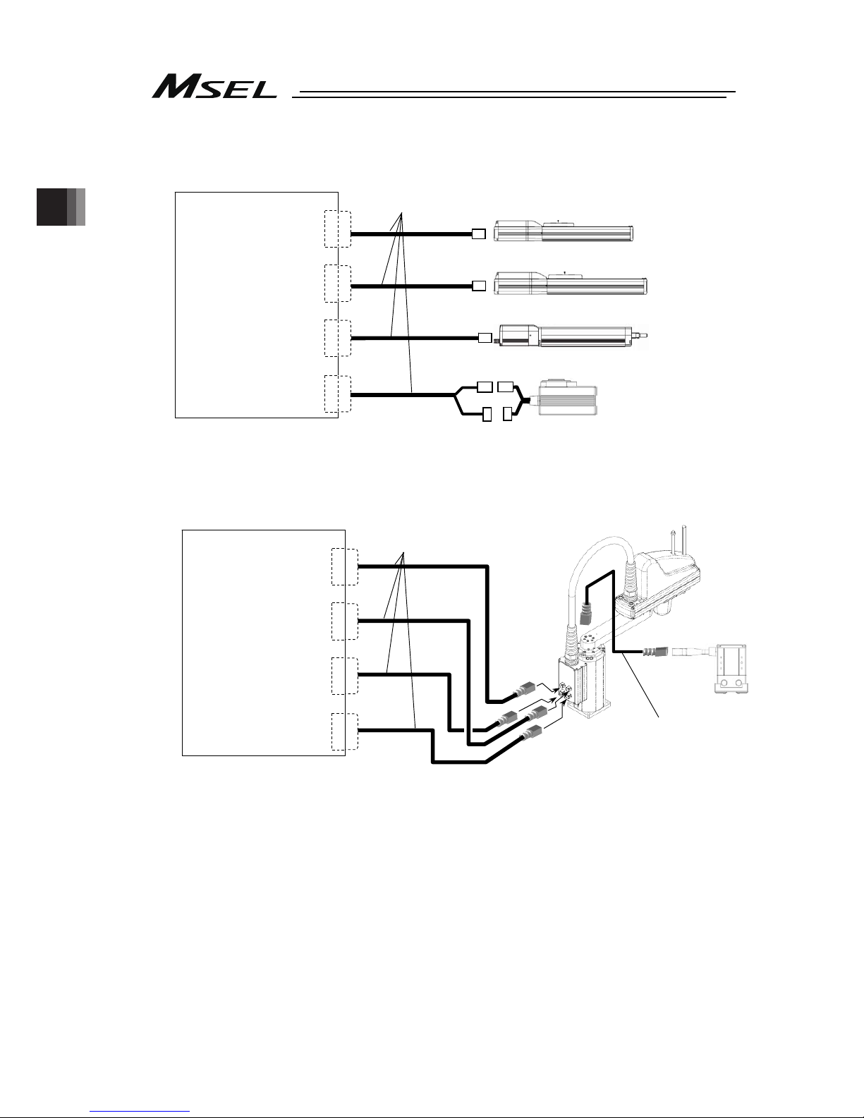
Chapter 2 Wiring
44
2.2.4 Motor Encoder Circuit
(1) Connection of Linear Axes
(2) Connection to IXP-4N3515, 4515 and IXP-3N3515, 4515 Equipped with Grippers.
MSEL
MPG1
MPG2
MPG3
MPG4
A
ctuator
Connection
Connector
When equipped with
grippers
CB-IXP-AT008-AS
MSEL
MPG1
MPG2
MPG3
MPG4
A
ctuator
Connection
Connector
Connection cable
(Note 1
)
Added axis
(RCP series)
Connection cable
(Note 1
)
CB-CAN-MPA
( : cable length Example. 030 = 3 m)
Page 53

Chapter 2 Wiring
45
(3) Connection to IXP-3N3515, 4515 and Additional Axes
Note 1 Applicable Connection Cable Model No. : cable length Example. 030 = 3 m
Model Cable Remarks
RCP2 CB-PSEP-MPA Robot cable from 0.5 to 20m
CB-APSEP-MPA Robot cable from 0.5 to 20m
RCP3
CB-APSEP-MPA-LC Standard cable from 0.5 to 20m
CB-CA-MPA-RB Robot cable from 0.5 to 20m
RCP4
(except for GR* type)
CB-CA-MPA Standard cable from 0.5 to 20m
CB-CAN-MPA-RB Robot cable from 0.5 to 20m
RCP4 (GR* type),
RCP5, RCP6, IXP
CB-CAN-MPA Standard cable from 0.5 to 20m
CB-CFA-MPA-RB Robot cable from 0.5 to 20m
RCP2
High-thrust type
CB-CFA-MPA Standard cable from 0.5 to 20m
CB-CFA2-MPA-RB Robot cable from 0.5 to 20m
RCP4
High-thrust type
CB-CFA2-MPA Standard cable from 0.5 to 20m
CB-CFA3-MPA-RB Robot cable from 0.5 to 20m
RCP5/6
High-thrust type
CB-CFA3-MPA Standard cable from 0.5 to 20m
Caution: In such case, give a number to each connector to avoid any mistake.
If the cable is not correctly connected, it might cause a damage to or
malfunction of the motor or PCB board.
MSEL
MPG1
MPG2
MPG3
MPG4
A
ctuator
Connection
Connector
Connection cable
(Note 1
)
Added axis
(RCP series)
Page 54

Chapter 2 Wiring
46
2.2.5 PIO Circuit
On MSEL Controller, Standard (I/O1) and Extension (I/O2) are available to mount.
The setting of the I/O parameters is required to use this PIO board.
[1] I/O Port Function Assignment
[2] Port Number Assignment for I/O Ports
[1] I/O Port Function Allocation
To Input Function Select No. 000 to 015 and Output Function Select No. 300 to 315, it is
available to set the dedicated functions and is available to assign to any input and output port.
For the other I/O port Nos., they can be used freely as the universal I/O port.
(1) Input Port Function Allocation
Parameter
Input
Function
Select
No.
No.
Set Value Function of an Input Signal
At the
delivery
0
Universal input
1
Program start (When indicated input port = 007 to 014 BCD,
start of indicated program number … ON-edge)
000 No.30
2
Program start (When indicated input port = 007 to 014, start of
binary indicated program number … ON-edge)
0 Universal input
001 No.31
1 Software reset signal (1sec continuous ON)
0 Universal input
002 No.32
1 Servo ON signal (edge input)
0 Universal input
1
Program automatically started when the power ON is reset in
AUTO mode and software is reset
003 No.33
2
Automatic starting program start (100sec continuous ON)
0
Universal input
004 No.34
1
All servo-axes soft interlock (Level signal of regular ON)
0
Universal input
005 No.35
1
Pause release (ON edge processing signal)
0
Universal input
006 No.36
1
Pause signal (level signal of regular ON)
No Consideration of Value in Input
Function Select 000
0 Universal input
Input Function Select 000=Setting 1
007 No.37
Input Function Select 000=Setting 2
1 Program No. select 0 bit
No Consideration of Value in Input
Function Select 000
0 Universal input
Input Function Select 000=Setting 1
008 No.38
Input Function Select 000=Setting 2
1 Program No. select 1 bit
No Consideration of Value in Input
Function Select 000
0 Universal input
Input Function Select 000=Setting 1
009 No.39
Input Function Select 000=Setting 2
1 Program No. select 2 bit
No Consideration of Value in Input
Function Select 000
0 Universal input
Input Function Select 000=Setting 1
010 No.40
Input Function Select 000=Setting 2
1 Program No. select 3 bit
No Consideration of Value in Input
Function Select 000
0 Universal Input
Input Function Select 000=Setting 1
011 No.41
Input Function Select 000=Setting 2
1 Program No. select 4 bit
No Consideration of Value in Input
Function Select 000
0 Universal input
Input Function Select 000=Setting 1
012 No.42
Input Function Select 000=Setting 2
1 Program No. select 5 bit
No Consideration of Value in Input
Function Select 000
0 Universal Input
Input Function Select 000=Setting 1
Input Function Select 000=Setting 2
1 Program No. select 6 bit
013 No.43
No Consideration of Value in Input
Function Select 000
2 Error reset (ON-edge)
Page 55
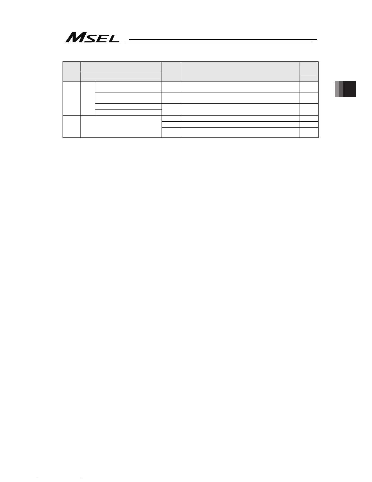
Chapter 2 Wiring
47
Parameter
Input
Function
Select
No.
No.
Set Value Function of an Input Signal
At the
delivery
No Consideration of Value in Input
Function Select 000
0 Universal input
No Consideration of Value in Input
Function Select 000
1
Driving source cut-off cancellation input (ON-edge)
(Effective when cancelling the cause of driving source cutoff)
Input Function Select 000=Setting 1
014 No.44
Input Function Select 000=Setting 2
2 Program No. select 7 bit
0 Universal input
1
Home-return operation on all the linear axes (ON-edge)
015 No.45
2
Home-return operation on all the incremental effective axes
(ON-edge)
Page 56

Chapter 2 Wiring
48
(2) Output Port Function Allocation
Parameter
Output
Function
Select
No.
No.
Set Value Function of an Input Signal
At the
delivery
0
Universal output
1
Error output at the operation cancellation level or more (ON)
2
Error output at the operation cancellation level or more (OFF)
3
Error output at the operation cancellation level or more +
emergency-stop output (ON)
4
Error output at the operation cancellation level or more +
emergency-stop output (OFF)
7
Output of an error of maintenance information alert function
related message level (Error No. 231 or 232) (ON)
300 No.46
8
Output of an error of maintenance information alert function
related message level (Error No. 231 or 232) (OFF)
0
Universal output
1
READY output (PIO trigger program operation available)
2
READY output (PIO trigger program operation available) and
without occurrence of any error at the operation cancellation
level or more
301 No.47
3
READY output (PIO trigger program operation available, and
without occurrence of any error at the cold start level or more)
0
Universal output
1
Emergency-stop output (ON)
302 No.48
2
Emergency-stop output (OFF)
0
Universal output
1
AUTO mode
303 No.49
2
Output during automatic operation (Other parameter No. 12)
0
Universal output
1
Output when all the effective axes at home position (= 0)
2
Output when home-return operation on all the effective axes
in complete condition (coordinates confirmed)
304 No.50
3
Output when all the effective axes in home preset coordinates
0
Universal output
1
1
st
axis in-position output (OFF when miss-pressing)
305 No.51
2
Output while the 1
st
axis servo is ON (system monitoring task
output)
0
Universal output
1
2
nd
axis in-position output (OFF when miss-pressing)
306 No.52
2
Output while the 2
nd
axis servo is ON (system monitoring task
output)
0
Universal output
1
3
rd
axis in-position output (OFF when miss-pressing)
307 No.53
2
Output while the 3
rd
axis servo is ON (system monitoring task
output)
0
Universal output
1
4
th
axis in-position output (OFF when miss-pressing)
308 No.54
2
Output while the 4
th
axis servo is ON (system monitoring task
output)
309 No.55 0
Universal output
310 No.56 0
Universal output
311 No.57 0
Universal output
312 No.58 0
Universal output
313 No.59 0
Universal output
314 No.60 0
Universal output
315 No.61 0
Universal output
Page 57

Chapter 2 Wiring
49
[2] Port Number Assignment for I/O Ports
With the following I/O parameters, assign the ranges and numbers of the ports used on PIO
board.
No. Parameter Name
Default
(Reference)
Input Range Remarks
1 I/O Port Assignment Type
0
(Reference
value)
0 to 20
0: Fixed assignment (No other than 0 can be set)
2
Input Port Start Number at
I/O1 Affixed Assignment
000 -1, 0 to 248
0+(multiple of 8)(Unavailable when it is negative
figure)
3
Standard
Output Port Start Number
at I/O1 Affixed Assignment
300 -1, 300 to 548
300+(multiple of 8)(Unavailable when it is negative
figure)
16
Input Port Start Number at
I/O2 Affixed Assignment
-1 -1, 0 to 288
0+(multiple of 8)(Unavailable when it is negative
figure)
17
Output Port Start Number
at I/O2 Affixed Assignment
-1 -1, 300 to 588
300+(multiple of 8)(Unavailable when it is negative
figure)
18 I/O2 Error Monitoring 1 0 to 1
0: Not to Monitor (The extension not applicable)
1: Monitor (Use the extension)
225
Extension
Extension I/O Controller 9 (Reference
value)
0 to 9
0 to 8:Extension not installed or other than PIO
installed
9:PIO (Extension installed)
283
Input Function Select 000
Physical Input Port No.
16
-1, 16 to 31,
48 to 299
Indicate port number to assign function set in I/O
Parameter No. 30 (Input port 000 when negative)
284
Input Function Select 001
Physical Input Port No.
17
-1, 16 to 31,
48 to 299
Indicate port number to assign function set in I/O
Parameter No. 31 (Input port 001 when negative)
285
Input Function Select 002
Physical Input Port No.
18
-1, 16 to 31,
48 to 299
Indicate port number to assign function set in I/O
Parameter No. 32 (Input port 002 when negative)
286
Input Function Select 003
Physical Input Port No.
19
-1, 16 to 31,
48 to 299
Indicate port number to assign function set in I/O
Parameter No. 33 (Input port 003 when negative)
287
Input Function Select 004
Physical Input Port No.
20
-1, 16 to 31,
48 to 299
Indicate port number to assign function set in I/O
Parameter No. 34 (Input port 004 when negative)
288
Input Function Select 005
Physical Input Port No.
21
-1, 16 to 31,
48 to 299
Indicate port number to assign function set in I/O
Parameter No. 35 (Input port 005 when negative)
289
Input Function Select 006
Physical Input Port No.
22
-1, 16 to 31,
48 to 299
Indicate port number to assign function set in I/O
Parameter No. 36 (Input port 006 when negative)
290
Input Function Select 007
Physical Input Port No.
23
-1, 16 to 31,
48 to 299
Indicate port number to assign function set in I/O
Parameter No. 37 (Input port 007 when negative)
291
Input Function Select 008
Physical Input Port No.
24
-1, 16 to 31,
48 to 299
Indicate port number to assign function set in I/O
Parameter No. 38 (Input port 008 when negative)
292
Input Function Select 009
Physical Input Port No.
25
-1, 16 to 31,
48 to 299
Indicate port number to assign function set in I/O
Parameter No. 39 (Input port 009 when negative)
293
Input Function Select 010
Physical Input Port No.
26
-1, 16 to 31,
48 to 299
Indicate port number to assign function set in I/O
Parameter No. 40 (Input port 010 when negative)
294
Input Function Select 011
Physical Input Port No.
27
-1, 16 to 31,
48 to 299
Indicate port number to assign function set in I/O
Parameter No. 41 (Input port 011 when negative)
295
Input Function Select 012
Physical Input Port No.
28
-1, 16 to 31,
48 to 299
Indicate port number to assign function set in I/O
Parameter No. 42 (Input port 012 when negative)
296
Input Function Select 013
Physical Input Port No.
29
-1, 16 to 31,
48 to 299
Indicate port number to assign function set in I/O
Parameter No. 43 (Input port 013 when negative)
297
Input Function Select 014
Physical Input Port No.
30
-1, 16 to 31,
48 to 299
Indicate port number to assign function set in I/O
Parameter No. 44 (Input port 014 when negative)
298
Input Function Select 015
Physical Input Port No.
31
-1, 16 to 31,
48 to 299
Indicate port number to assign function set in I/O
Parameter No. 45 (Input port 015 when negative)
299
Output Function Select 300
Physical Input Port No.
316
0, 316 to 331,
348 to 599
Indicate port number to assign function set in I/O
Parameter No. 46 (Output port 301 when 0)
300
Output Function Select 301
Physical Input Port No.
317
0, 316 to 331,
348 to 599
Indicate port number to assign function set in I/O
Parameter No. 47 (Output port 302 when 0)
301
Output Function Select 302
Physical Input Port No.
318
0, 316 to 331,
348 to 599
Indicate port number to assign function set in I/O
Parameter No. 48 (Output port 303 when 0)
302
Output Function Select 303
Physical Input Port No.
319
0, 316 to 331,
348 to 599
Indicate port number to assign function set in I/O
Parameter No. 49 (Output port 304 when 0)
303
Output Function Select 304
Physical Input Port No.
320
0, 316 to 331,
348 to 599
Indicate port number to assign function set in I/O
Parameter No. 50 (Output port 305 when 0)
304
Output Function Select 305
Physical Input Port No.
321
0, 316 to 331,
348 to 599
Indicate port number to assign function set in I/O
Parameter No. 51 (Output port 306 when 0)
Page 58

Chapter 2 Wiring
50
No. Parameter Name
Default
(Reference)
Input Range Remarks
305
Output Function Select 306
Physical Input Port No.
322
0, 316 to 331,
348 to 599
Indicate port number to assign function set in I/O
Parameter No. 52 (Output port 307 when 0)
306
Output Function Select 307
Physical Input Port No.
323
0, 316 to 331,
348 to 599
Indicate port number to assign function set in I/O
Parameter No. 53 (Output port 308 when 0)
307
Output Function Select 308
Physical Input Port No.
324
0, 316 to 331,
348 to 599
Indicate port number to assign function set in I/O
Parameter No. 54 Output port 309 when 0)
308
Output Function Select 309
Physical Input Port No.
325
0, 316 to 331,
348 to 599
Indicate port number to assign function set in I/O
Parameter No. 55 (Output port 310 when 0)
309
Output Function Select 310
Physical Input Port No.
326
0, 316 to 331,
348 to 599
Indicate port number to assign function set in I/O
Parameter No. 56 (Output port 311 when 0)
310
Output Function Select 311
Physical Input Port No.
327
0, 316 to 331,
348 to 599
Indicate port number to assign function set in I/O
Parameter No. 57 (Output port 312 when 0)
311
Output Function Select 312
Physical Input Port No.
328
0, 316 to 331,
348 to 599
Indicate port number to assign function set in I/O
Parameter No. 58 (Output port 313 when 0)
312
Output Function Select 313
Physical Input Port No.
329
0, 316 to 331,
348 to 599
Indicate port number to assign function set in I/O
Parameter No. 59 (Output port 314 when 0)
313
Output Function Select 314
Physical Input Port No.
330
0, 316 to 331,
348 to 599
Indicate port number to assign function set in I/O
Parameter No. 60 (Output port 315 when 0)
314
Output Function Select 315
Physical Input Port No.
331
0, 316 to 331,
348 to 599
Indicate port number to assign function set in I/O
Parameter No. 61 (Output port 316 when 0)
(Note) The parameter settings at delivery may differ depending on the type of the extension I/O slot (I/O2).
[Refer to 3.2 Receiving and Forwarding of I/O Signals Necessary for Operation]
Page 59
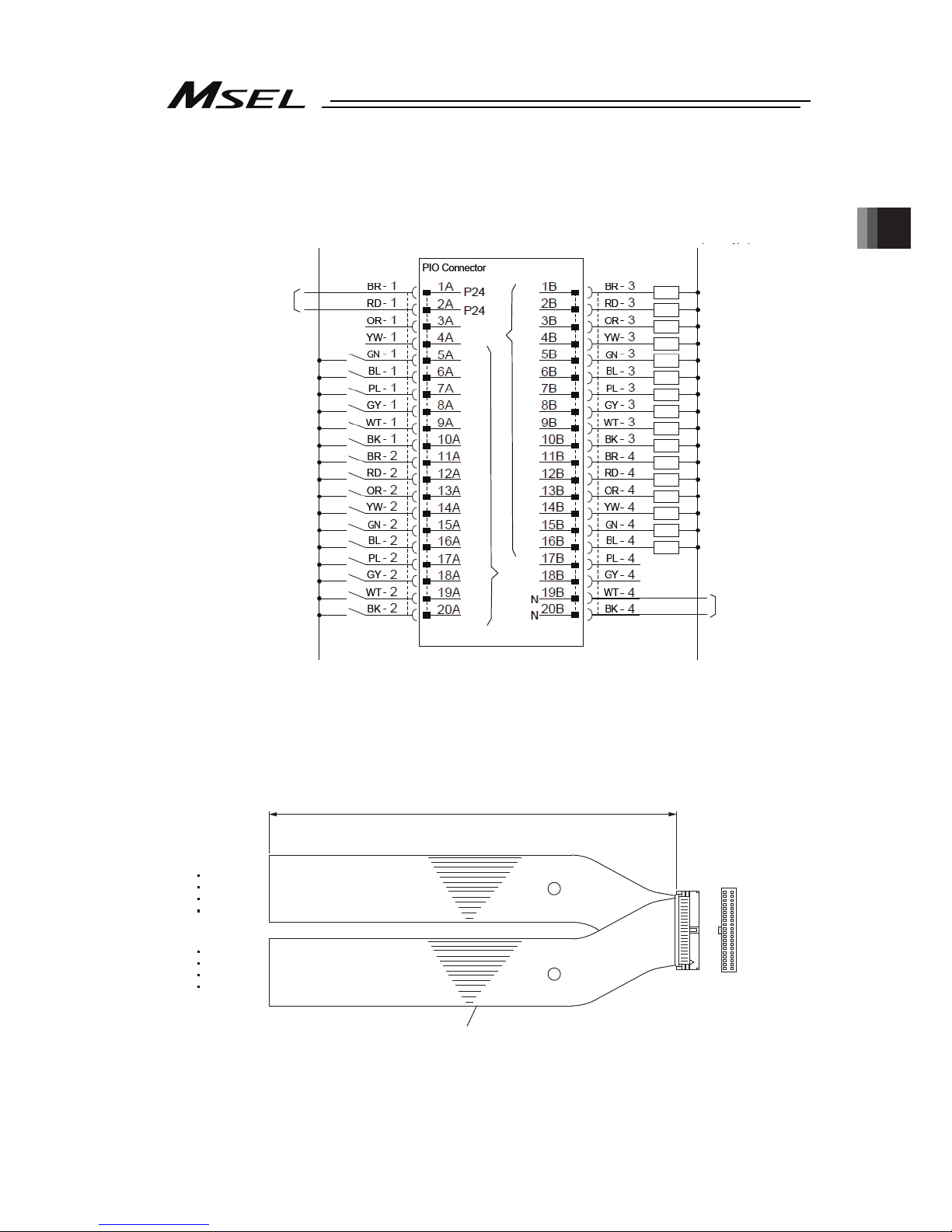
Chapter 2 Wiring
51
[3] Wiring
1) Standard type (I/O1)
24VDC (NPN Type)
0V (PNP Type)
0V
24VDC (PNP Type)
24VDC
0V (NPN Type)
016
017
018
019
020
021
022
023
024
025
026
027
028
029
030
031
316
317
318
319
320
321
322
323
324
325
326
327
328
329
330
331
Output function
is parameter
setup
Input function
is parameter
setup
● Use the attached cable for the I/O connection.
Model : CB-PAC-PIO ( indicates the cable length L. Example. 020 = 2m)
Flat Cable (20-core) × 2
BK-4 (20B)
BR-3 (1B)
BK-2 (20A)
BR-1 (1A)
20A 20B
1A 1B
Half Pitch MIL Socket
HIF6-40D-1.27R (Hirose Electric)
A
B
L
No treatment
conducted
No treatment
conducted
Page 60

Chapter 2 Wiring
52
2) ExtensionI/O (I/O2)
24VDC (NPN Type)
0V (PNP Type)
0V
24VDC (PNP Type)
General-purpose
input
General-purpose
output
24VDC
0V (NPN Type)
048
049
050
348
349
350
● Use the attached cable for the I/O connection.
Model : CB-PAC-PIO ( indicates the cable length L. Example. 020 = 2m)
Flat Cable (20-core) × 2
BK-4 (20B)
BR-3 (1B)
BK-2 (20A)
BR-1 (1A)
20A 20B
1A 1B
Half Pitch MIL Socket
HIF6-40D-1.27R (Hirose Electric)
A
B
L
No treatment
conducted
No treatment
conducted
Page 61

Chapter 2 Wiring
53
2.2.6 Connection to Absolute Battery Box (only for PC/PG/PCF/PGF Type
Simple Absolute)
(Note) Do not attempt to plug in or take off the cable with force in the tilted direction to the
connector.
MSEL
Absolute
Battery
Connector
Absolute
Battery Box
MSEL-ABB-□-□
CB-MSEL-AB005
Cable Length 0.5m
Page 62
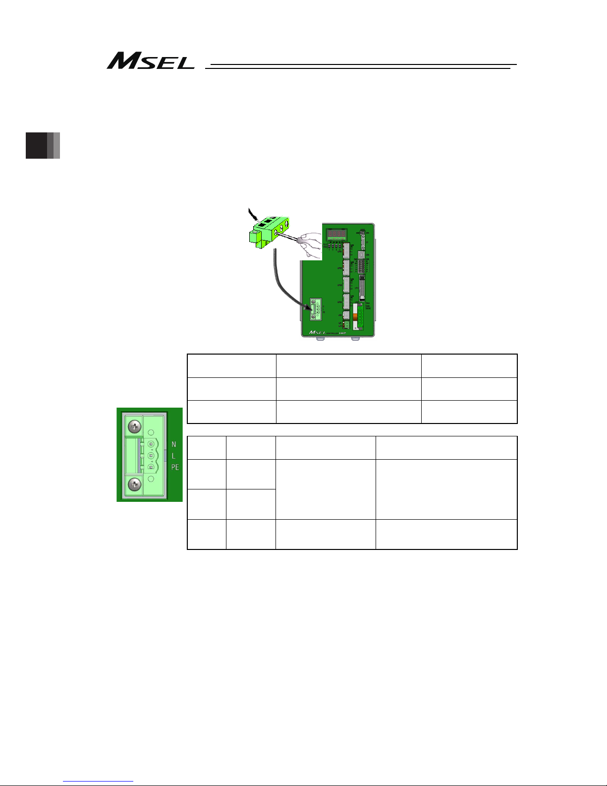
Chapter 2 Wiring
54
2.3 Wiring Method
2.3.1 Connection to AC Power Input Connector
The wire of the power supply is to be connected to the enclosed connector (plug).
Strip the sheath of the applicable wires for 7mm and insert them to the connector.
When inserting, turn the screw on the side of the inlet to the left with a slotted screwdriver to
open the inlet. After inserting the wires, turn the screw to the right with a slotted slotted
screwdriver to fix the wires.
Drive Power Supply
Input Connector
Model Remarks
Cable side MSTB2,5/3-STF-5,08 (SK: N-PE)
(PHOENIX CONTACT)
Enclosed in standard
package
Controller side DFK-MSTB2,5/3-GF-5,08
(PHOENIX CONTACT)
Pin No.
Signal
Name
Description Applicable Cable Diameter
3 N
2 L
Power supply input
(100 AC to 230V)
1.25 to 0.5mm
2
(AWG16 to 20)
Select the cable thickness
allowable for the current figured
out in the power capacity.
1 PE
Protective grounding
wire
3
2
1
Front view of
connector on
controller side
Page 63

Chapter 2 Wiring
55
2.3.2 Wiring the Emergency Stop Circuit (System I/O)
Construction is made with the emergency stop input and the input terminal of the enable
signal.
The wires are to be connected to the enclosed connectors (plugs). Peel the sheath on the
applicable cable for 10mm, and insert to a connector.
Item PC/PCF/PCX Type PG/PGF/PGX Type
Drive-source cutoff
circuit
Built-in
(Hard-wired configuration)
Conforming category B B, 1 to 3
Redundancy in safety
circuit
- Achieved by an external circuit.
Operation upon
emergency stop
Decelerate the actuator at the emergency deceleration (All axes
parameter No. 24, No. 205, each axis parameter No. 136) to a
stop, turn OFF the servo, and then cut off the drive source.
Recovery from
emergency stop
Recover by cancelling emergency stop by system I/O
External output of
emergency stop status
Possible. (Set by I/O parameter No. 48.)
[Refer to 2.2.2 and 2.2.3 for the basic circuit configuration.]
Left Right
System I/O Connector Model Remarks
Cable side
DFMC1,5/6-ST-3,5
(PHOENIX CONTACT)
Enclosed in
standard package
Controller side
DMC1,5/6-G1-3,5P20THR
(PHOENIX CONTACT)
Pin
No.
Signal Name Class Description
Applicable
cable
diameter
12 EMGIN IN Emergency stop detection input
11 EMGOUT +24V
24-V power output for emergency stop
detection input
(30V DC, Max0.5A)
10 EMGS1+ line+
9 EMGS1- line-
They are the cables to connect to the
emergency stop circuit on the teaching
pendant when a teaching pendant is to be
connected. When no teaching pendant is to
be connected, 1+ and 1- are short-circuited
the PC/PCF/PCX type.
8 EMGS2+ line+
Left
side
7 EMGS2- line-
(Used in PG/PGF type, Not used in PC/PCF
type)
They are the cables to connect to the
emergency stop circuit on the teaching
pendant when a teaching pendant is to be
connected. When no teaching pendant is to
be connected, 2+ and 2- are short-circuited.
6 ENBIN IN Enable detection input
5 ENBOUT +24V
24-V power output for enable detection input
(30V DC, Max0.5A)
4 ENBS1+ line+
3 ENBS1- line-
They are the cables to connect to the enable
circuit on the teaching pendant when a
teaching pendant is to be connected. When
no teaching pendant is to be connected, 1+
and 1- are short-circuited the PC/PCF/PCX
type.
2 ENBS2+ line+
Right
side
1 ENBS2- line-
(Used in PG/PGF type, Not used in PC/PCF
type)
They are the cables to connect to the
emergency stop circuit on the teaching
pendant when a teaching pendant is to be
connected. When no teaching pendant is to
be connected, 2+ and 2- are short-circuited.
1.25 to
0.3mm
2
(AWG16
to 22)
Front view of
connector on
controller side
12 6
7 1
Page 64

Chapter 2 Wiring
56
The following pin numbers are connected with a short-circuiting cable at the delivery.
Pins 4 and 5
Pins 3 and 6
Pins 10 and 11
Pins 9 and 12
2.3.3 Wiring for Actuator
Connect the relay cables to the actuator connectors.
Check in the instruction manual of each actuator for the details of the relay cables.
Actuator Connection
Connector
Model Remarks
Cable side
PADP-24V-1-S
Controller side
S24B-PADSS-1
Note 1 The pin assignment of the connector that the high-thrust type axis
can be connected and that of the connector that all the other
types of axis can be connected are different from each other.
Pin No.
Signal
Name
Description
Applicable Wire
Diameter
1
A
Motor driving A-phase
2 VMM
Motor power
3
B
Motor driving B-phase
4 VMM
Motor power
5
/A
Motor driving /A-phase
6
/B
Motor driving /B-phase
7 LS +
Limit switch positive side
8 LS -
Limit switch negative side
9 BK +
Brake release positive side
10 BK -
Brake release negative side
11 ABS_SA Absolute encoder differential + input
12 ABS_SB Absolute encoder differential - input
13 A + Encoder A-phase differential + input
14 A - Encoder A-phase differential - input
15 B + Encoder B-phase differential + input
16 B - Encoder B-phase differential - input
5V
Encoder power supply
(except for high-thrust axis)
17
(Note 1)
NC Disconnected (High-thrust axis )
18 /PS
Encoder line driver enable output
19 GND
Ground
20 LSGND
Ground for limit switch
NC
Disconnected
(except for high-thrust axis)
21
(Note 1)
5V
Encoder power supply
(High-thrust axis)
22 NC Disconnected
23 NC Disconnected
24 FG Grounding
Cable dedicated for
IAI products
Front view of
connector on
controller side
1
2
23
24
Page 65

Chapter 2 Wiring
57
2.3.4 Wiring for Motor Driving Power Line Connector
This wiring is to be constructed when it is required to have the driving power source shut
externally. In case of using the driving source cutoff circuit inside the controller, use the
controller under the condition of the enclosed short-circuiting cable being connected.
The wires are to be connected to the enclosed connectors (plugs). Peel the sheath on the
applicable cable for 10mm, and insert to a connector.
Motor Driving
Power Supply
Line Connector
Model Remarks
Cable side
FKIC2,5HC/2-ST-5,08
(PHOENIX CONTACT)
Enclosed in standard
package
Controller side IC2,5HC/2-G-5,08
Pin
No.
Signal
Name
Description Applicable Wire Diameter
2 MPI
Motor power supply external
input
1 MPO
Motor power supply external
output
KIV1.25 to 0.75mm
2
(AWG16 to 18)
Select the cable thickness
allowable for the current
figured out in the power
capacity.
2.3.5 Wiring to Single Absolute Battery Unit
Connect the absolute battery unit and controller for simple absolute type.
Absolute Battery
Connector
Model Remarks
Cable side CZHR-12V-S
Controller side S12B-PADSS-1
Pin
No.
Signal
Name
Description
Applicable Wire
Diameter
1 GND 0V
2 1BAT Axis No. 1 Absolute battery
3 1BAT_TMP
Axis No. 1
Absolute battery temperature
sensor
4 2BAT Axis No. 2 Absolute battery
5 2BAT_TMP
Axis No. 2
Absolute battery temperature
sensor
6 3BAT Axis No. 3 Absolute battery
7 3BAT_TMP
Axis No. 3
Absolute battery temperature
sensor
8 4BAT Axis No. 4 Absolute battery
9 4BAT_TMP
Axis No. 4
Absolute battery temperature
sensor
10 GND 0V
11 NC Disconnected
12 NC Disconnected
Cable dedicated
for IAI products
2
1
Front view of
connector on
controller side
Front view of
connector on
controller side
1
2
11
12
Page 66
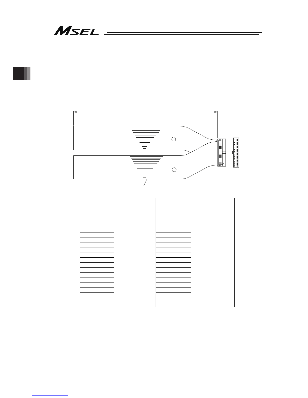
Chapter 2 Wiring
58
2.3.6 Wiring for PIO
The connection of I/O to the controller is to be carried out using the dedicated I/O cable. The
cable length is shown in the model code of the controller. Please check the controller model
code. There are 2m for standard, 3m and 5m as an option. Up to 10m can be enabled sold
separately. [Refer to “1.1.5 How to Read the Model”]
Also, the end of the cable harness to be connected to the host controller (PLC, etc.) is just cut
and no treatment is conducted so the wiring layout can be performed freely.
Model : CB-PAC-PIO
( indicates the cable length L. Example. 020 = 2m)
L
B
A
Flat Cable (20-core) × 2
20A 20B
1A 1B
Half Pitch MIL Socket
HIF6-40D-1.27R (Hirose Electric)
No treatment
conducted
No treatment
conducted
No.
Cable
Color
Wiring No.
Cable
Color
Wiring
1A BR-1 1B BR-3
2A RD-1 2B RD-3
3A OR-1 3B OR-3
4A YW-1 4B YW-3
5A GN-1 5B GN-3
6A BL-1 6B BL-3
7A PL-1 7B PL-3
8A GY-1 8B GY-3
9A WT-1 9B WT-3
10A BK-1 10B BK-3
11A BR-2 11B BR-4
12A RD-2 12B RD-4
13A OR-2 13B OR-4
14A YW-2 14B YW-4
15A GN-2 15B GN-4
16A BL-2 16B BL-4
17A PL-2 17B PL-4
18A GY-2 18B GY-4
19A WT-2 19B WT-4
20A BK-2
Flat Cable
○
A
(Press Welding)
AWG28
20B BK-4
Flat Cable○B
(Press Welding)
AWG28
[Refer to 2.2.5 PIO Circuit for the signal assignment for each cable]
Page 67
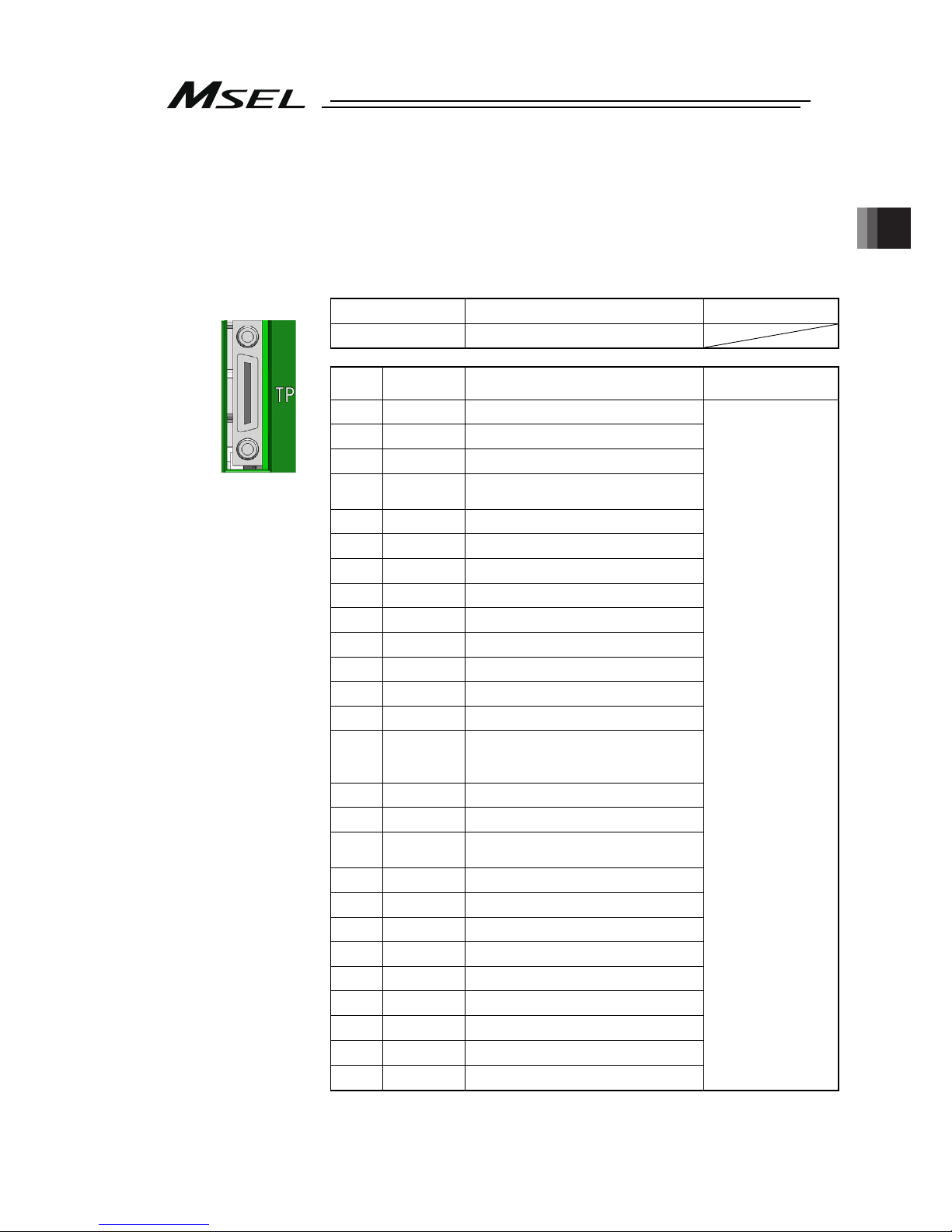
Chapter 2 Wiring
59
2.3.7 Wiring for the Teaching Tool (SIO Connector, USB Connector)
Connect a teaching tool such as the PC software.
Connection of either RS232C or USB is available. (USB is prioritized when both are connected
at the same time.)
Apply the enclosed dummy plug (DP-4S) to the teaching connector when operation mode
setting switch is set to AUTO in PG/PGF/PGX type.
[1] SIO Connector
SIO Connector
Model Remarks
Controller side HDR-EC26LFDT1-SLD+
Pin No.
Signal
Name
Description
Applicable Wire
Diameter
1 GND 0V
2 EMGS Emergency stop status output
3 VCC 6.5V power input connector
DTR
Terminal ready (Connected to DSR
inside)
5 EMGS2 + Emergency stop contact output 2+
6 EMGS2 - Emergency stop contact output 2-
7 NC Unconnected
8 RSVVCC 24V power input connector
9 EMGS1 - Emergency stop contact output 1-
10 NC Unconnected
11 NC Unconnected
12 EMGS1 + Emergency stop contact output 1+
13 RTS Connected to DSR externally
14 CTS
Connected to RTS externally,
connector connection detection
input.
15 TXD Transmit data
16 RXD Receive data
17 DSR
Equipment ready (Connected to
DSR inside)
18 NC Unconnected
19 NC Unconnected
20 NC Unconnected
21 NC Unconnected
22 ENBS2 + Enable contact output 2 +
23 ENBS1 - Enable contact output 1 -
24 ENBS1 + Enable contact output 1 +
25 ENBS2 - Enable contact output 2 -
26 GND 0V
Cable dedicated for
IAI products
Front view of
connector on
controller side
4
Page 68

Chapter 2 Wiring
60
[2] USB Connector
USB Connector
Model Remarks
Controller side
UBBS-4R-D14-4D B type
Pin No.
Signal
Name
Description
Applicable Wire
Diameter
1 V
BUS
5V
2
D- Communication data -
3
D+ Communication data +
4 GND 0V
USB cable
Caution:
1)
Set “Operation Mode Setting Switch” to “MANU” side when a teaching device
is connected.
2)
Turn the power OFF before disconnecting a teaching pendant.
3
USB connector and SIO connector cannot be used at the same time. USB
connector is prioritized.
4)
When using a USB connector in MANU Mode, apply the dummy plug
(DP-4S) or connect the cable enclosed to the PC software to the SIO
connector as the enable signal detection activates.
Front view of
connector on
controller side
* SIO and USB cannot be connected at the same time.
Page 69

Chapter 3 Operation
61
Chapter 3 Operation
3.1 Types of Operations
The MSEL controller is a programming controller that can operate without a host controller.
Programming for this controller uses IAI’s dedicated programming language (SEL language).
[Refer to the separate SEL Language Programming Manual.]
Operation method
Operation in a standalone
(independent) mode
[Refer to the 3.4.1 Auto Start
upon Power On]
Operation via PIO interface
Operation via serial
communication commands
Operation using a teaching tool
Operation with PIO (24V I/O)
[Refer to the 3.4.2 Starting a Program by Specifying its
Program Number]
Operation with Fieldbus communication (option)
(DeviceNet, CC-Link, PROFIBUS-DP, EtherNet/IP,
EtherCAT and PROFINET-IO are supported.)
[Refer to the separate operation manual for each Fieldbus
protocol.]
Operation with Serial communication (RS232C)
[Refer to the separate SEL language programming manual.]
Operation with Ethernet communication (option)
[Refer to the separate Ethernet operation manual.]
Page 70
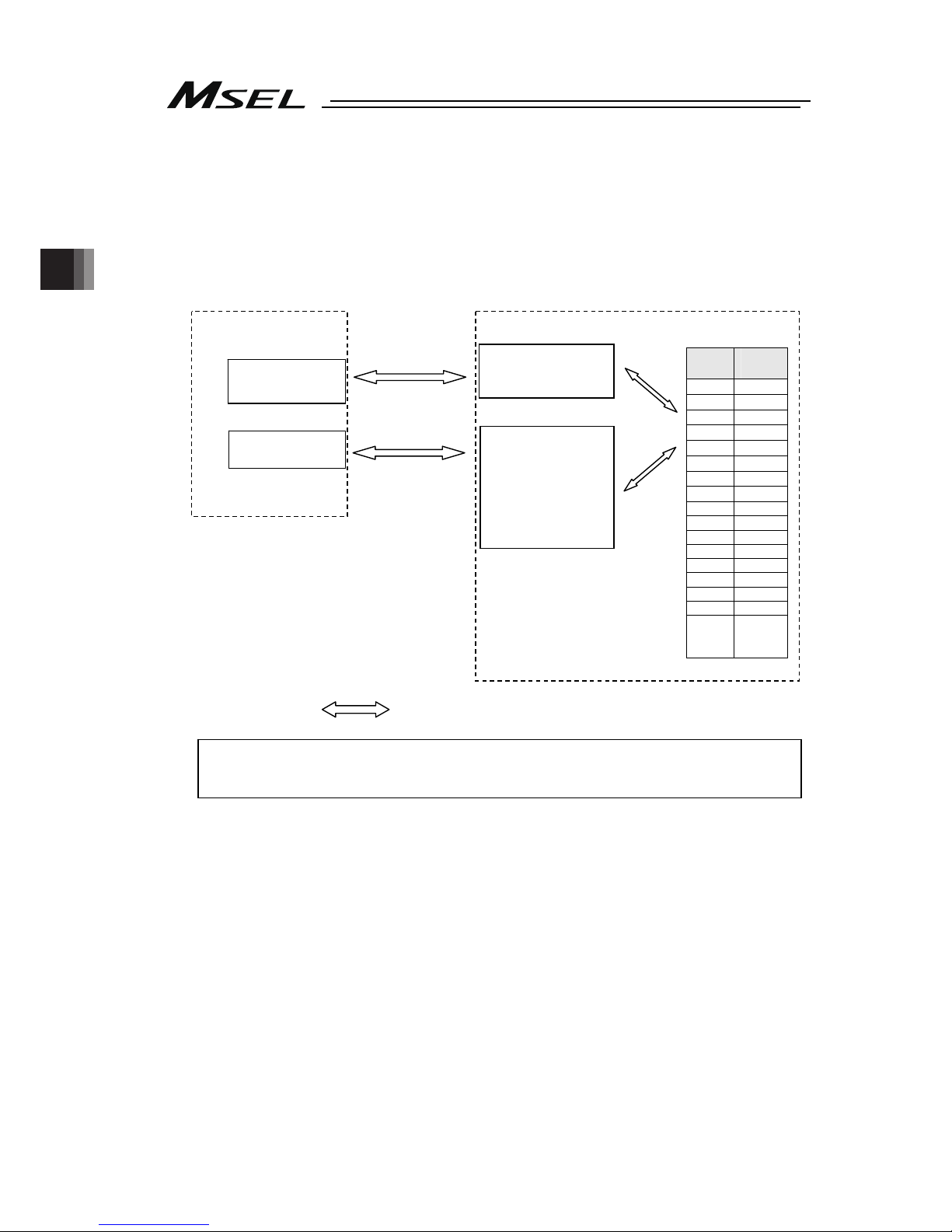
Chapter 3 Operation
62
3.2 Receiving and Forwarding of I/O Signals Necessary for Operation
The I/O port can deliver the data with the MSEL controller and external signals through
interface.
One port can exchange data for one contact (1 bit).
Data is exchanged via PIOs (24V I/Os) or over a fieldbus.
Either a PIO or fieldbus can connect to each port at a time.
Whether to use PIO or fieldbus is set by a parameter.
indicates flow of data.
Refer to Section 2.2.5 for the PIO interface.
For the each fieldbus, refer to each instruction manual.
Host Controller
I/O unit
Fieldbus
master unit
MSEL Controller
I/O Ports
I/O interface
• Standard I/O
• Extension I/O
Fieldbus
interface
• DeviceNet
• CC-Link
• PROFIBUS-DP
• EtherNet/IP
Input
Port
Output
Port
16 316
17 317
18 318
19 319
20 320
21 321
22 322
23 323
24 324
25 325
26 326
27 327
28 328
29 329
30 330
31 331
32
332
Data exchange
Data exchange
Connected
internally.
(Assignments
are set by
parameters.)
Page 71

Chapter 3 Operation
63
(1) I/O Map
The factory-set I/O port numbers and functions of the MSEL controller are shown below.
The functions of the I/O port can be changed using the I/O parameter setting.
[Refer to 2.2.5 PIO Circuit and Chapter 6. I/O Parameter]
1) When I/O2 is Not Fieldbus type (Type of extension I/O is either of E/NP/PN/SE1/SE2/IA)
Type Port No. Function Type Port No. Function
000 300 ALM (LED on the front panel)
001 301 RDY (LED on the front panel)
002 302 EMG (LED on the front panel)
003 303 System reservation
004 304 HPS (LED on the front panel)
005 305
006 306
007 307
008 308
009 309
010 310
011 311
012 312
013 313
014 314
Internal
DI
(I/O1)
015
System reservation
Internal
DO
(I/O1)
315
System reservation
016 Program start 316 Alarm output
017 317 READY output
018 318 Emergency-stop output
019 319
020 320
021 321
022
General-purpose input
322
023
Program number indication (BCD:1・BIN:1) *
323
024
Program number indication (BCD:2・BIN:2) *
324
025
Program number indication (BCD:4・BIN:4) *
325
026
Program number indication (BCD:81・BIN:8) *
326
027
Program number indication (BCD:10・BIN:16) *
327
028
Program number indication (BCD:20・BIN:32) *
328
029
Program number indication (BCD:40・BIN:64) *
329
030 330
External
DI
(I/O1)
031
General-purpose input
External
DO
(I/O1)
331
General-purpose output
032 332 7-segment user display digit
033 333 7-segment user display digit
034 334 System reservation
035 335 System reservation
036 336 System reservation
037 337 7-segment display refresh
038 338 7-segment user/system alternate
039 339 7-segment user display specification
040 340 DT0 (7-segment user display bit)
041 341 DT1 (7-segment user display bit)
042 342 DT2 (7-segment user display bit)
043 343 DT3 (7-segment user display bit)
044 344 DT4 (7-segment user display bit)
045 345 DT5 (7-segment user display bit)
046 346 DT6 (7-segment user display bit)
Internal
DI
(I/O1)
047
System reservation
Internal
DO
(I/O1)
347 System reservation
External
DI
(I/O2)
048
to
295
General-purpose input
External
DO
(I/O2)
348
to
595
General-purpose output
* Switching over between BCD and BID in Program Number Indication should be conducted in IO
Parameter No. 30 Input Function Select 000.
(1:Program start BCD, 2:Program start binary(BIN))
Page 72

Chapter 3 Operation
64
2) When I/O2 is Fieldbus type (Type of extension I/O is either of CC/CC2/DV/DV2/PR/EP/EC/PRT)
Type Port No. Function Type Port No. Function
000 300 ALM (LED on the front panel)
001 301 RDY (LED on the front panel)
002 302 EMG (LED on the front panel)
003 303 System reservation
004 304 HPS (LED on the front panel)
005 305
006 306
007 307
008 308
009 309
010 310
011 311
012 312
013 313
014 314
Internal
DI
(I/O1)
015
System reservation
Internal
DO
(I/O1)
315
System reservation
External
DI
(I/O1)
016
to
031
General-purpose input
External
DO
(I/O1)
316
to
331
General-purpose output
032 332 7-segment user display digit
033 333 7-segment user display digit
034 334 System reservation
035 335 System reservation
036 336 System reservation
037 337 7-segment display refresh
038 338 7-segment user/system alternate
039 339 7-segment user display specification
040 340 DT0 (7-segment user display bit)
041 341 DT1 (7-segment user display bit)
042 342 DT2 (7-segment user display bit)
043 343 DT3 (7-segment user display bit)
044 344 DT4 (7-segment user display bit)
045 345 DT5 (7-segment user display bit)
046 346 DT6 (7-segment user display bit)
Internal
DI
(I/O1)
047
System reservation
Internal
DO
(I/O1)
347 System reservation
048 Program start
348 Alarm output
049 349 READY output
050 350 Emergency-stop output
051 351
052 352
053 353
054
General-purpose input
354
055
Program number indication (BCD:1・BIN:1) *
355
056
Program number indication (BCD:2・BIN:2) *
356
057
Program number indication (BCD:4・BIN:4) *
357
058
Program number indication (BCD:81・BIN:8) *
358
059
Program number indication (BCD:10・BIN:16) *
359
060
Program number indication (BCD:20・BIN:32) *
360
061
Program number indication (BCD:40・BIN:64) *
361
062 362
063
General-purpose input
363
General-purpose output
External
DI
(I/O2)
064
to
295
General-purpose input
External
DO
(I/O2)
364
to
595
General-purpose output
* Switching over between BCD and BID in Program Number Indication should be conducted in IO
Parameter No. 30 Input Function Select 000.
(1:Program start BCD, 2:Program start binary(BIN))
Page 73

Chapter 3 Operation
65
3.3 Starting the Controller
3.3.1 Turning on the Power and Cutoff
(1) Power on Procedure
The following procedure is applied for cases where the parameters are the same as those at
delivery, and the unit is not in the error occurrence mode or emergency stop mode.
Also, the number allocation for the I/O ports is shown as the same as the delivery in this
description.
1) After confirming that the wirings are performed properly, supply power to the peripheral
devices. If PIO is in use, supply 24V DC for PIO. In the case that it is not used, the power
supply is not required, but, set I/O Parameter No. 10 and No. 18 to “0: Unmonitored”.
2) Supply the main power.
3) Once the startup of the controller (CPU startup) is held in normal condition, I/O Port No.
317 turns ON.
A timing chart of the above operation is shown below.
Main power
Controller state
Peripheral device
Initialized/Self checking Normal operation state
Prior supply
Status of power supply and
connection diagnosed at initializing
(DIO power supply and fieldbus:
setting at delivery)
(2) Power Cutoff on Procedure
Shut the power on the peripheral devices at the same time as or after the shutoff of the main
power.
Shut the power on the peripheral devices
at the same time as or after the shutoff of
the main power
Main power
Peripheral device
Caution: Leave it for 5 seconds or more after shutting the power off when you turn it back
on.
Page 74
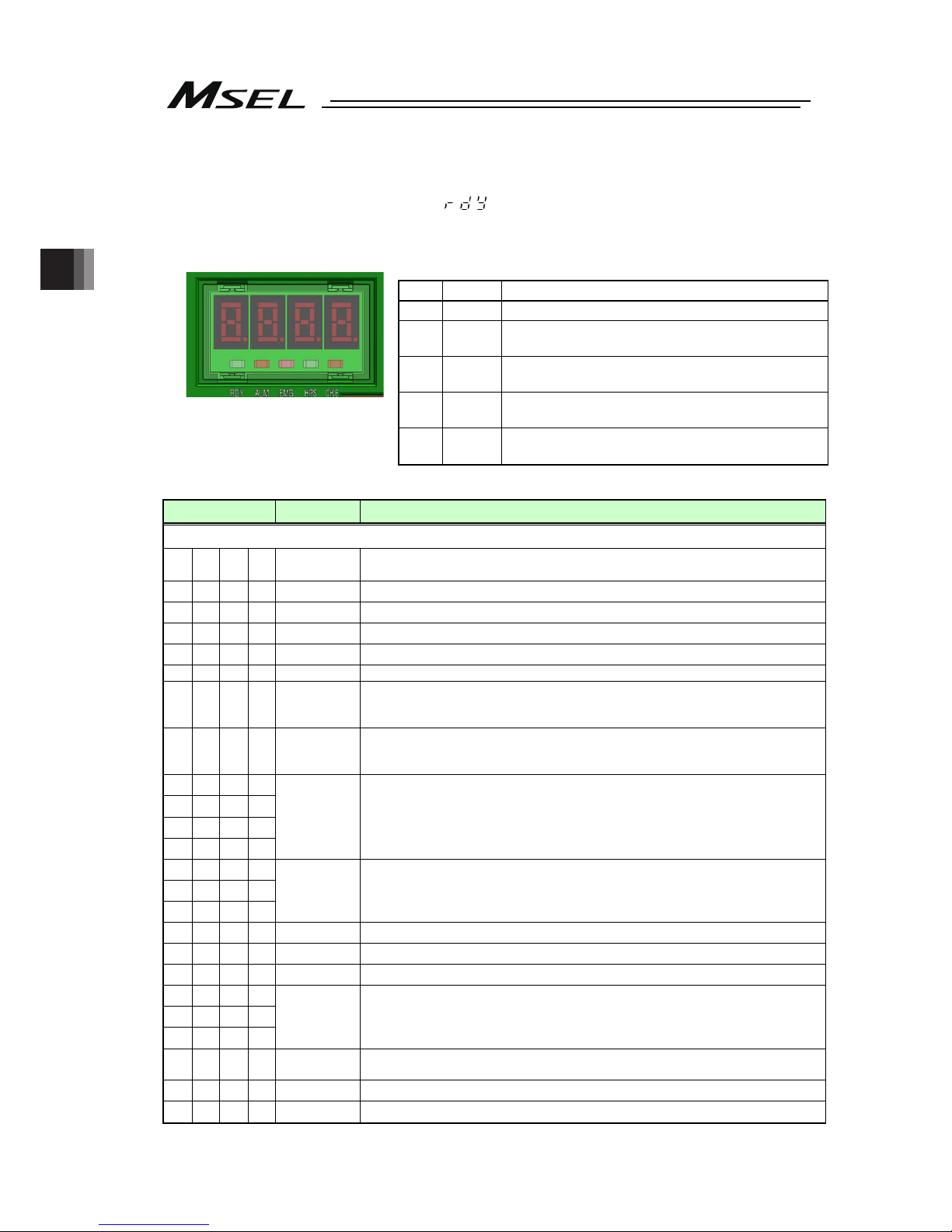
Chapter 3 Operation
66
3.3.2 Panel Window Display
The 4-digit, 7-segment LED shows the controller status.
When the unit is started up normally, “ ” is displayed after the initial processing display.
If an indication “E***” is displayed, check “Trouble Shooting” in Chapter 7. For others shown on
7-segment LED display, refer to the display list of the panel window stated below.
Displayed Contents of LED Lamps on Controller
No. Name Status when LED is on
1) RDY CPU Ready (Program operation available)
2)
ALM
CPU Alarm CPU Alarm (error in operation cancel
level or higher) generated
3)
EMG
Emergency stop, error in CPU hardware or
power-related hardware error
4)
HPS
All axes have completed home-return operation
state
5)
CKE
Error in system lock or power-related hardware
error
Panel Window Display List (1/2) Control Codes for Application
Display Priority
(Note )
Description
[Control Codes for Application]
A C F 1
The AC power is cut off. (Momentary power failure or power-supply power
cutoff)
E F * * 1 A system-shutdown level error is present
8 8 8 8 2 Operation test on all 7-seg LED lamps (Initialization sequence)
I n * * 2 Initialization sequence number display
I n n * 2 Field network board initialization sequence number display
P r d 3 Data written to flash ROM
E r G
4
(Display
switches in turn)
In emergency stop condition
e n b
4
(Display
switches in turn)
The enable switch (deadman’s switch/safety gate) is OFF
E E * *
E d * *
E 6 * *
E 5 * *
4
(Display
switches in turn)
A cold-start level error is present. (Most critical level system error)
E C * *
E b * *
E 4 * *
4
(Display
switches in turn)
An operation-cancellation level error is present (Most critical level system error)
- r P 5 Waiting for a drive-source cutoff reset signal to be input
- r S 5 Operation is paused (waiting for restart)
- I L C 6 All axis servos are interlocked
E A * *
E 9 * *
E 2 * *
7 A message level error is present (Most critical level system error)
P * * * 8
A program is running (last started program).
(The applicable program number is ***.)
A r d y 8 Ready status (Startup complete in AUTO mode)
r d y 8 Ready status (Startup complete in MANU mode)
Note 1 The smaller the value to be displayed, the higher the priority.
1) 2) 3) 4) 5) 6)
Page 75

Chapter 3 Operation
67
Panel Window Display List (2/2) Control Codes for Core
Display Priority
(Note )
Description
[Control Codes for Core]
E E * * 1 A cold-start level error is present.
E C * * 1 An operation-cancellation level error is present.
E A * * 2 A message level error is present.
J P A 2 Jump to the application
C H F C 2 Flash ROM check process (core)
C H F A 2 Flash ROM check process (application)
C H S d 2 SDRAM check process
Note 1 The smaller the value to be displayed, the higher the priority.
Page 76

Chapter 3 Operation
68
3.3.3 Status LED
It shows the status of PIO or Fieldbus plugged to the extension I/O connector.
(1) PIO Type Status LED
: Illuminating : OFF
Name
Lamp
condition
Color Description
RUN
Green
In the normal operation
(Flashes when initialization completes)
ERR
Orange PIO power voltage (24V DC) drop error
(2) DeviceNet Type Status LED
: Illuminating : OFF : Flashing
Name
Lamp
condition
Color Description
In the normal operation
Green
Configuration not established or setting
incomplete
Error impossible to recover
Orange
Error possible to recover
MS
Green /
Orange
Self-checking test
In the normal communication
Green
Online status (no connection)
Critical link error
Orange
Connection timeout
NS
Green /
Orange
Self-checking test
(3) CC-Link Type Status LED
: Illuminating : OFF : Flashing
Name
Lamp
condition
Color Description
RUN
Green In the normal operation
Error occurrence
(CRC, station setting, baud rate setting)
ERR
Orange
Change made to station number and baud rate
setting at reset cancel
(4) PROFIBUS-DP Type Status LED
: Illuminating : OFF : Flashing
Name
Lamp
condition
Color Description
Initialization complete
Green
Initialization complete (with diagnosis event)
MS
Orange Exception error generated
In the normal communication
Green
Online status (in clearance condition)
NS
Orange Error occurrence (parameter, configuration)
Page 77

Chapter 3 Operation
69
(5) EtherNet/IP Type Status LED
: Illuminating : OFF : Flashing
Name
Lamp
condition
Color Description
In operation condition and under control of
scanner (master)
Green
Setting of construction information incomplete, or
scanner (master) in idling condition
Fatal malfunction (exception condition or critical
error)
MS
Orange
Light malfunction possible to recover
Online status
(Connection established on one or more)
Green
Online status (connection not being established)
Critical error such as IP address duplication
NS
Orange
Timeout in connection on one or more
(6) Simple Absolute Status LED Lamps (PC/PG/PCF/PGF type)
: Illuminating : OFF : Flashing
Name
Lamp
condition
Color Description
Green Battery fully charged
Orange Battery in charge
0
Red Battery not connected
Name
Lamp Condition of 1
(Color)
Lamp Condition of 2
(Color)
Description
(Green) (Green) Absolute reset complete
(Red) (Green) Absolute reset incomplete
1, 2
- (Red) Alarm
Page 78

Chapter 3 Operation
70
3.3.4 Position Table and Program Creation and Writing
Create a position table and create a program using the SEL language.
Perform the teaching, etc., and register the required coordinates in the position table. Also,
create the program using the SEL language.
[Refer to the separate SEL language programming manual.]
Write the position table and program data in the controller.
[Refer to the separate instruction manual for your PC software.]
Caution: A margin of error could accumulate between each pitch if the incremental
(relative position indication) movement commands
*
are repeated continuously.
To avoid accumulation of errors, utilize the absolute position indication
commands such as MOVP and MOVL.
* MVPI, MVLI, TMPI, TMLI
Page 79

Chapter 3 Operation
71
3.4 Program Operation
For the operation there are two ways of start-up. One is the automatic start-up of the set
program No. and the other is to start up with the program No. selected externally.
3.4.1 Auto Start upon Power On
After the power is turned ON, the program with its No. registered in the MSEL controller, can
be automatically started up.
1) Connect the PC software and set the I/O parameter No. 33 to “1” and set the program No.
to be started up in the parameter No. 1 (for others)
Parameter
type and
No.
Set Value
Description
0 Input port 019 is designated as a general-purpose input.
1
(factory default)
In the AUTO mode, when the power is turned ON or the
software reset is performed, the program No. set in parameter
No. 1 (for others) is executed.
The input port 019 can be used as a universal input port.
I/O
parameter
No. 33
2
When input port 019 is turned ON, the program whose number
is set in other parameter No. 1 is executed. When this port is
turned OFF, all currently running programs stop.
I/O
parameter
No. 286
19
Indicate the port number to assign the feature in I/O Parameter
No. 33 “Input Function Select 003”
Other
parameter
No. 1
1 to 255
Set the program number of the program you want to start
automatically.
2) Set the operation mode setting switch on the MSEL controller to the AUTO position.
3) Turn off the power and then turn it back on.
4) The MSEL controller is restarted (the RDY signal turns ON to indicate a successful start),
after which the specified program starts.
Program execution
Min0.01sec
Main power
(AC100 to 230V)
RDY output
(output forme the MSEL)
* Output from Output Port
No. 317 when I/O
Parameter No. 47 is other
than 0
Program
Page 80

Chapter 3 Operation
72
Caution: After the power is turned on, unexpected movements of the robot may create
dangerous situations.
For safety, provide an interlock whereby the program is started only after a start
confirmation signal has been input from a pushbutton switch, etc.
An example of operation is given below.
1) Set the parameter No. 33 to “2”.
The program starts when input port 019 is turned ON, and stops when the port is turned
OFF.
2) Set the operation mode setting switch on the MSEL controller to the AUTO position.
3) Turn off the power and then turn it back on.
4) Make sure input port 019 is turned ON after a wait time of 0.01 sec following the start of the
MSEL controller (the RDY signal turns ON to indicate a successful start).
5) The specified program starts.
RDY output
(output forme the MSEL)
* Output from Output Port
No. 317 when I/O
Parameter No. 47 is other
than 0
Input port 019
Program
3)
4)
Program execution
Min0.01sec
Page 81
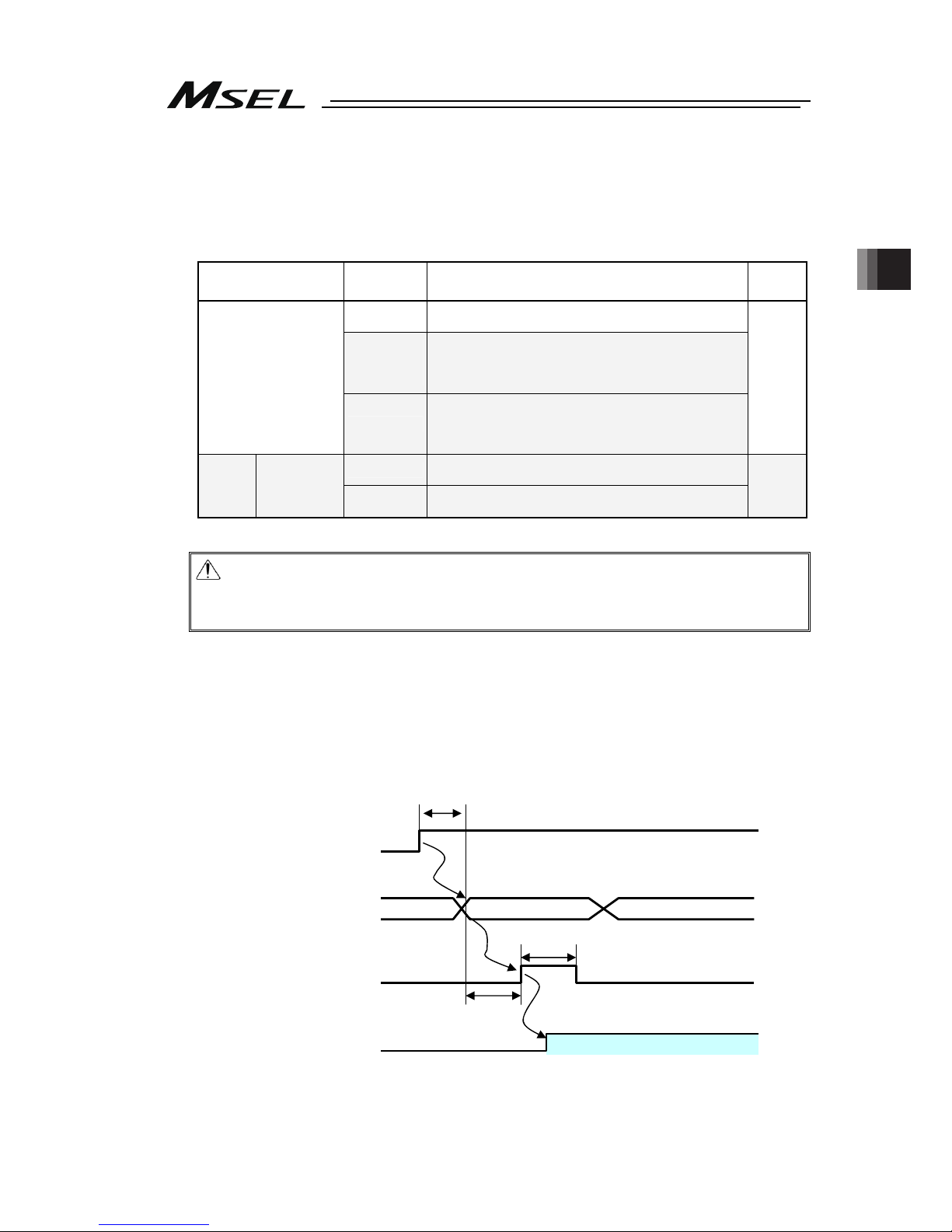
Chapter 3 Operation
73
3.4.2 Starting a Program by Specifying its Program Number
The program to be started up, can be started with its number specified externally and start-up
signal input.
1) Connect the PC software and perform the setting, referring to the set values in the
following table.
Parameter type and
No.
Set Value Description Setting
0
Input port 016 is designated as a general-purpose
input.
1
(factory
default)
After the program number to be started up, is set in
the input port 023 (LSB) to 030 (MSB) with BCD,
turning ON the input port 016 starts up the program.
Turning ON the input port 016 for 0.1 sec or more.
I/O parameter
No. 30
2
After the program number to be started up, is set in
the input port 023 (LSB) to 030 (MSB) with BCD,
turning ON the input port 016 starts up the program.
Turning ON the input port 016 for 0.1 sec or more.
1 or 2
0
Input ports 023 to 030 are set as general-purpose
inputs.
No. 30
= 1 or 2
I/O
parameters
No. 37 to 44
1
(No.44=“2” )
Input ports 023 to 030 are set as start program
number specification ports.
1
(No.44=
“2” )
Caution: The maximum number of programs is 255. However, the programs able to
start up with the BCD Code indication are from No. 1 to No.99. To start up No.
100 to No. 255 when using BCD Code, start them up with using the automatic
start program startup or the program startup command “EXPG”.
2) Input the program No. 0.01sec or more after the MSEL controller is started up (after
normal start-up = RDY signal ON).
3) Set in the input ports set by I/O parameter No. 30, the program number of the program
you want to start.
4) Set the program No. and 0.05 sec. or more later, turn ON the input port 016 (program
start).
5) Turn ON input port 016 (program start) and keep it ON for 0.1 sec.
6) The specified program starts.
RDY output
(output from the XSEL)
* Output from Output Port No.
317 when I/O Parameter No.
47 is other than 0
Program No.
(output from the host)
Program start
(output from the host)
Program
Program execution
1) Min0.01sec
Program number
2)
4)
3) Min0.05sec
Min0.1sec
5)
Page 82

Chapter 3 Operation
74
3.4.3 7-Segment Display SEL Program
The 7-segment LED in the panel window on the normally displays the information from the
system, but it is able to change the display of the 7-segment LED by the SEL program created.
(SEL program and system are displayed in turn.)
For control of 7-segment LED, port No. 332, 333 and 337 to 346 are used.
Port No. Function
332 Indication of digits to show on 7-seg display
333 Indication of digits to show on 7-seg display
334
335
336
Cannot be used
337 7-segment display refresh
338 7-segment SEL/system alternate
339 7-segment display specification
340 DT0 (7-segment user display bit)
341 DT1 (7-segment user display bit)
342 DT2 (7-segment user display bit)
343 DT3 (7-segment user display bit)
344 DT4 (7-segment user display bit)
345 DT5 (7-segment user display bit)
346 DT6 (7-segment user display bit)
347 Cannot be used
1) In port No. 332 and 333, indicate the digit number for the segment to be operated.
On/Off of port and indicated digit number 0 : OFF 1 : ON
No.332 0 1 0 1
No.333 0 0 1 1
Digit to be operated 1 2 3 4
Caution: In the parameter setting at the delivery, the port numbers are as shown above.
Page 83

Chapter 3 Operation
75
2) In port No. 339, establish the setting for the switchover of SEL program display and system
display.
Setting
Value
Function
0 Display of system is conducted
Port No. 339
1 Display of SEL program is conducted
3) When setting is established No. 339 = 1, and Port No. 338 gets set to 1, SEL Program
Display and System Display should be conducted one after another.
Caution: When DO No. 338 is set to 0 and DO No. 339 is set to 1;
User display is shown and no switchover in every one second.
System display (error display) should be conducted when it occurs an
operation cancel level error, cold start level error or system shutdown level
error.
System display (error display) would not be conducted when it occurs a
message level error or is in a condition other than an error occurrence (data
flash ROM under writing, etc.).
When it is required to display the condition in a message level error or in a
condition other than an error occurrence, set DO No. 338 to 1 to make it
mutual display.
4) Pote No. 340 to 346 correspond to the 7-segment LED each display bits.
5) Display is shown no the 7-segment LED by on-edge (0 → 1 → 0) of port No. 337.
(The 7-segment pattern set in port No. 340 to 346 is shown on the digit set in port No. 332
and 333.)
Caution: Parameter setting in normal delivery should be the port number above.
Page 84

Chapter 3 Operation
76
How to Use
1) Establish the display mode setting in port No. 338 and 339.
2) Set the digit to display (update) in port No. 332 and 333.
3) Establish the display pattern setting of the 7-segment display in port No. 340 to 346.
4) Have port No. 337 (Refresh) turned OFF → ON → OFF. (Update conducted with ON-edge)
To display other digits, repeat the steps 2) to 4).
After the SEL program for display is finished, the display lasts until Port No. 339 is turned OFF.
Reference Program : To show 1234
No E N Cnd Cmnd Operand 1 Operand 2 Pst Comment
1 LET 99 3
2 OUT 338 339
Display of User and
System by Turns
3 BTOF 337
4 * 1st digit data set
5 LET 99 0
6 OUT 332 333 Indicate 1st Digit
7 LET 99 3 3 = Display Data ‘1’
8 OUT 340 346 7-segment Pattern 1
9 BTON 337 Refresh ON
10 BTOF 337 Refresh OFF
11 * 2nd digit data set
12 LET 99 1
13 OUT 332 333 Indicate 2nd Digit
14 LET 99 118 118 = Display Data ‘2’
15 OUT 340 346 7-segment Pattern 2
16 BTON 337 Refresh ON
17 BTOF 337 Refresh OFF
18 * 3rd digit data set
19 LET 99 2
20 OUT 332 333 Indicate 3rd Digit
21 LET 99 103 118 03Display Data ‘3’
22 OUT 340 346 7-segment Pattern 3
23 BTON 337 Refresh ON
24 BTOF 337 Refresh OFF
25 * 4th digit data set
26 LET 99 3
27 OUT 332 333 Indicate 4th Digit
28 LET 99 75 75 = Display Data ‘4’
29 OUT 340 346 7-segment Pattern 4
30 BTON 337 Refresh ON
31 BTOF 337 Refresh OFF
32
33 EXIT
Page 85

Chapter 4 Home-Return / Absolute Reset
77
Chapter 4 Home-Return / Absolute Reset
There are three types for the encoder to measure the current position of the actuator.
1) For Incremental Type, it is necessary to conduct home-return operation when the power is
turned on.
2) For Battery-less Absolute Type, it is necessary to absolute reset only when in motor
replacement and in an occurrence of an absolute error.
3) The coordinate data is retained in the battery backup for Simple Absolute Type. Even though it
is not necessary to performance a home-return operation each time, it is necessary to have an
absolute reset conducted in the first time to start up the system or after replacing the battery.
Timing to Have Home-Return
and Absolute Reset
Encoder
Type
Mounted Actuator
Series
Home-Return Absolute Reset
Setting
in Each
Axis No.
38
Section
to Pick
up
Incremental
RCP4 to 2
(Linear, rotary
axis and
grippers)
When
power is
turned on
0 4.1
RCP5, RCP6
(Linear, rotary
axis and
grippers)
2 4.2
Battery-less
Absolute
IXP
(SCARA Robot)
• At motor replacement
• When absolute error
generated
2 4.3
Simple
Absolute
RCP4 to 2
(Linear, rotary
axis and
grippers)
• At initial startup
• When the power to the
controller is turned OFF and
battery is replaced
• When the encoder cable is
taken off the controller
2 4.4
Described below is the procedure for each. (In this manual, states the procedure for the PC
software. For how to treat and process on a teaching pendant, refer to an instruction manual for
each product)
4.1 Home-Return Preparation (Incremental Type)
1) Turn OFF the power to the controller.
2) Connect the controller and PC to a teaching tool with a dedicated cable.
3) Turn ON the power to the controller, and connect a teaching tool such as the PC software.
4) Confirm that there is no error generated (and “rdy” is displayed on the 7-seg LED panel
window).
5) After pressing the servo-ON button, press the home-return button. Once the home-return
operation is complete, the home position gets established.
Page 86

Chapter 4 Home-Return / Absolute Reset
78
4.2 Absolute Reset Preparation (for Battery-less Absolute Type except for
SCARA Robot)
Caution : It is not necessary to have an absolute reset in ordinary case, however, make
sure to have the absolute reset conducted when an absolute error is occurred or
after dismantlement of the robot for a reason such as motor replacement.
Otherwise, it may cause a malfunction or critical operation error on the robot.
1) Turn ON the power to the controller, and connect the PC software.
2) Make sure to have a backup of the parameters before conducting.
Select [Parameter] → [Edit] from the menu in the PC software to show the parameter edit
window. Press “Save As” button in the parameter edit window to save the parameters to
file data.
3) Select [Controller] → [Calibration Home/Abs. Encoder Reset] from the menu in the PC
software.
4) A warning window shows up. Check the content and click “OK”.
Page 87

Chapter 4 Home-Return / Absolute Reset
79
5) “Calibration Home / Abs. Encoder Reset” window appears.
Select the tab for the Axis 4 (O1).
6) Click on “Start” button while the [Axis 4 (O1)] tab is selected, and a warning window shows
up. Release the emergency stop, check the content and click “Yes” to start the
home-return operation on the axis subject to home-position adjustment.
Caution : As soon as clicking “Yes”, the home-return operation starts.
In case there is any interference to peripheral equipment during the home-return
operation, the home-return operation completes at the position of interference,
and the proper home position cannot be acquired. Make sure not to have
interference to peripheral equipment.
Page 88

Chapter 4 Home-Return / Absolute Reset
80
7) Close “Calibration Home / Abs. Encoder Reset” window after the home-return operation is
complete. After that, the window switches to “Flash ROM Writing” window.
Put a check mark on “Parameter” and click “Yes” to start writing. After it is finished,
conduct a software reset.
Page 89
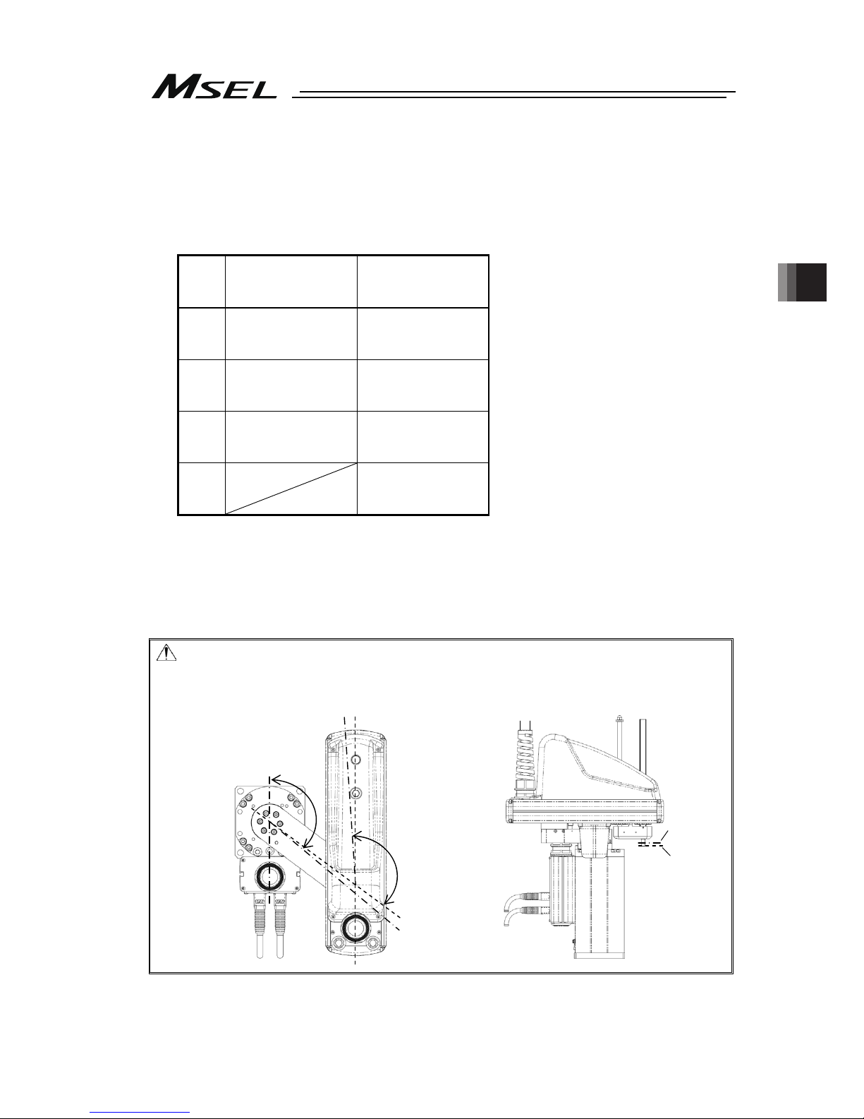
Chapter 4 Home-Return / Absolute Reset
81
4.3 Absolute Reset for SCARA Robot (Battery-less Absolute Type)
It is available to perform operation on SCARA Robot without having anything special as an
absolute reset has already been conducted before delivered out from our factory. It is
necessary to have an absolute reset when an absolute error generates or the robot is
dismantled for such a reason as motor replacement work.
Model
of the
Robot
3N3515-WA
/3N4515-WA
(3-axis Absolute Type)
4N3515-WA
/4N4515-WA
(4-axis Absolute Type)
J1
axis
(Absolute reset
(Note 1)
)
↓
Operation
(Absolute reset
(Note 1)
)
↓
Operation
J2
axis
(Absolute reset
(Note 1)
)
↓
Operation
(Absolute reset
(Note 1)
)
↓
Operation
Z axis
(Absolute reset
(Note 1)
)
↓
Operation
(Absolute reset
(Note 1)
)
↓
Operation
R axis
(Absolute reset
(Note 1)
)
↓
Operation
Note 1 It is necessary to perform when the absolute error is occurred or after dismantled the
robot for a reason such as to replace motor
Described below is how to conduct an absolute reset.
(In this manual, states the procedure for the PC software. For how to treat and process on a
teaching pendant, refer to an instruction manual for each product)
Caution: Home-return operation is an action to press towards the mechanical stopper.
Make sure to secure enough space for home-return posture and also there is no
interference to the peripherals during the home-return operation.
Vertical Axis
Mechanical
Stopper
Position
Vertical
Axis Home
Position
J1 Axis Home
Position
130 deg
130 deg
J2 Axis Home
Position
J2 Axis
Mechanical
Stopper
Position
J1 Axis Mechanical
Stopper Position
Page 90
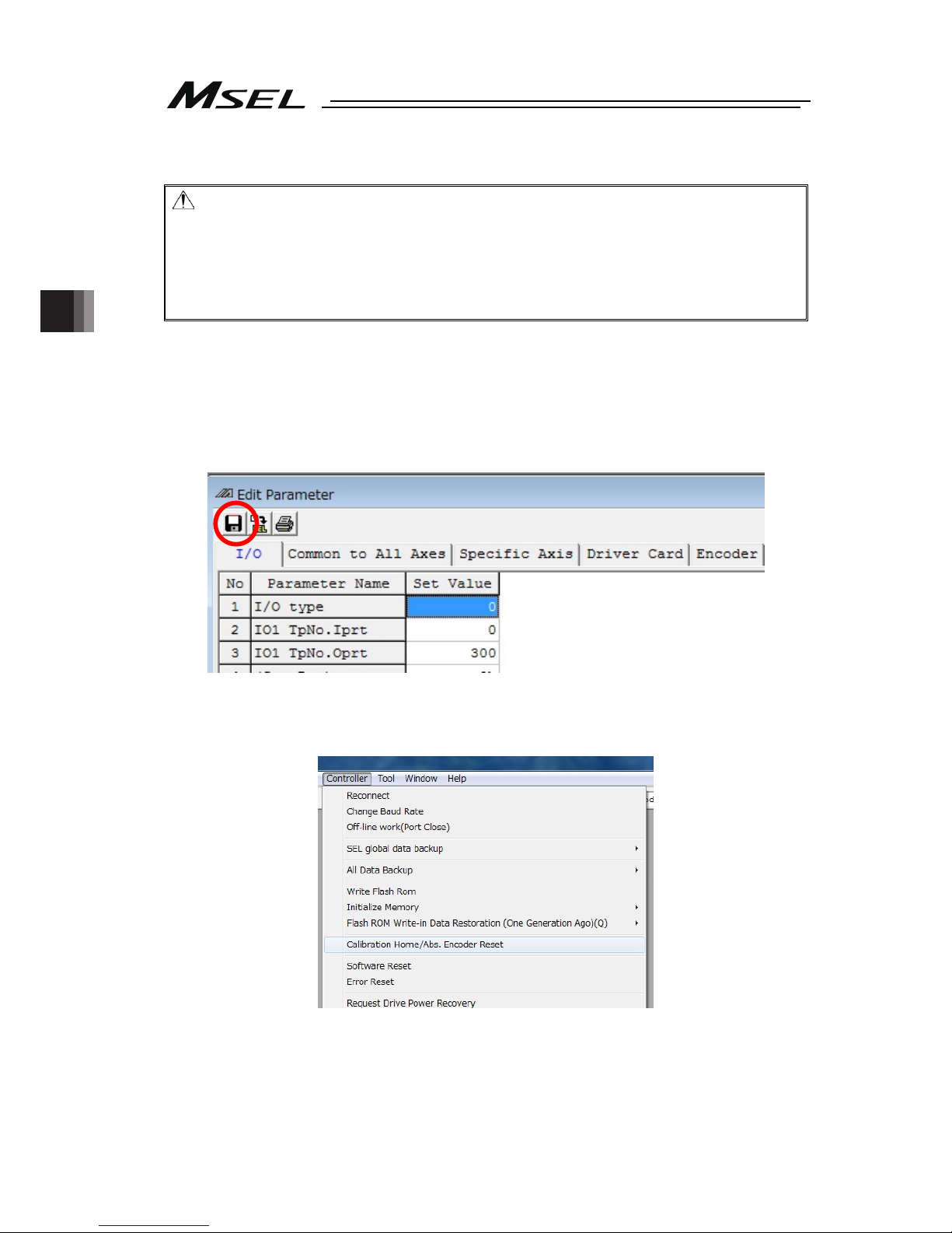
Chapter 4 Home-Return / Absolute Reset
82
4.3.1 Absolute Reset Preparation
Caution: • It is not necessary to have an absolute reset in ordinary case, however, make
sure to have the absolute reset conducted when an absolute error is occurred or
after dismantlement of the robot for a reason such as motor replacement.
Otherwise, it may cause a malfunction or critical operation error on the robot.
• There may be a case that the indicated coordinates for positioning point cannot
be achieved before and after the absolute reset is conducted.
[Refer to “Scattered Positioning Points” in IXP SCARA Robot instruction]
1) Turn ON the power to the controller, and connect the PC software.
2) Make sure to have a backup of the parameters before conducting.
Select [Parameter] → [Edit] from the menu in the PC software to show the parameter edit
window. Press “Save As” button in the parameter edit window to save the parameters to
file data.
3) Select [Controller] → [Calibration Home/Abs. Encoder Reset] from the menu in the PC
software.
Page 91
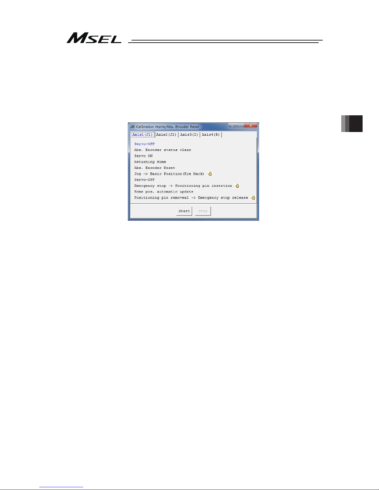
Chapter 4 Home-Return / Absolute Reset
83
4) A warning window shows up. Check the content and click “OK”.
5) “Calibration Home/Abs. Encoder Reset” appears. Select the tab for the axis that requires
the absolute reset.
Select a tab for the axis to have home position adjustment from J1 (Axis 1) Axis or J2
(Axis 2) Axis.
Process for Z (Axis 3) Axis and R (Axis 4) Axis are to be conducted after J1 and J2.
Page 92

Chapter 4 Home-Return / Absolute Reset
84
6) Click on “Start” button while the [Axis 1 (J1)] or [Axis 2 (J2)] tab is selected, and a warning
window shows up. Release the emergency stop, check the content and click “Yes”.
Home-return operation starts on the axis subject to absolute reset.
Caution: As soon as clicking “Yes”, the home-return operation starts. The standard home
position is the posture stated in the beginning of this section.
In case there is any interference to peripheral equipment during the home-return
operation, the home-return operation completes at the position of interference,
and the proper home position cannot be acquired. In such cases, it may cause a
crash or unexpected operation, which could cause malfunction or critical
operation error to the robot or the peripherals. Make sure to secure enough space
for home-return posture to avoid any interference to the peripherals during the
home-return operation.
7) “Jog -> Basic position” window appears once the home-return operation is complete.
Press “← (-)” and “→ (+)” buttons to move the arm to a place near the datum position.
[Refer to the figure in Step (8) for the datum position] Also, change “Jog Vel (JOG speed)”
and “Inc. Distance (inching distance)” if necessary. Click “OK” once the arm gets near the
datum position. Click “OK” when moving the arm new the datum position manually by
hand.
Page 93

Chapter 4 Home-Return / Absolute Reset
85
Home-Position Adjusting Tool (φ4)
J2 axis
8) Have the emergency stop conducted, and insert the home-position adjustment tool (φ4) at
the datum position of J1 axis or J2 axis.
9) With the home-position adjustment tool (φ4) being inserted, click “OK” in “Emergency stop
-> Positioning pin insertion” window.
Home-Position Adjusting Tool
(
φ4)
J1 axis
Page 94
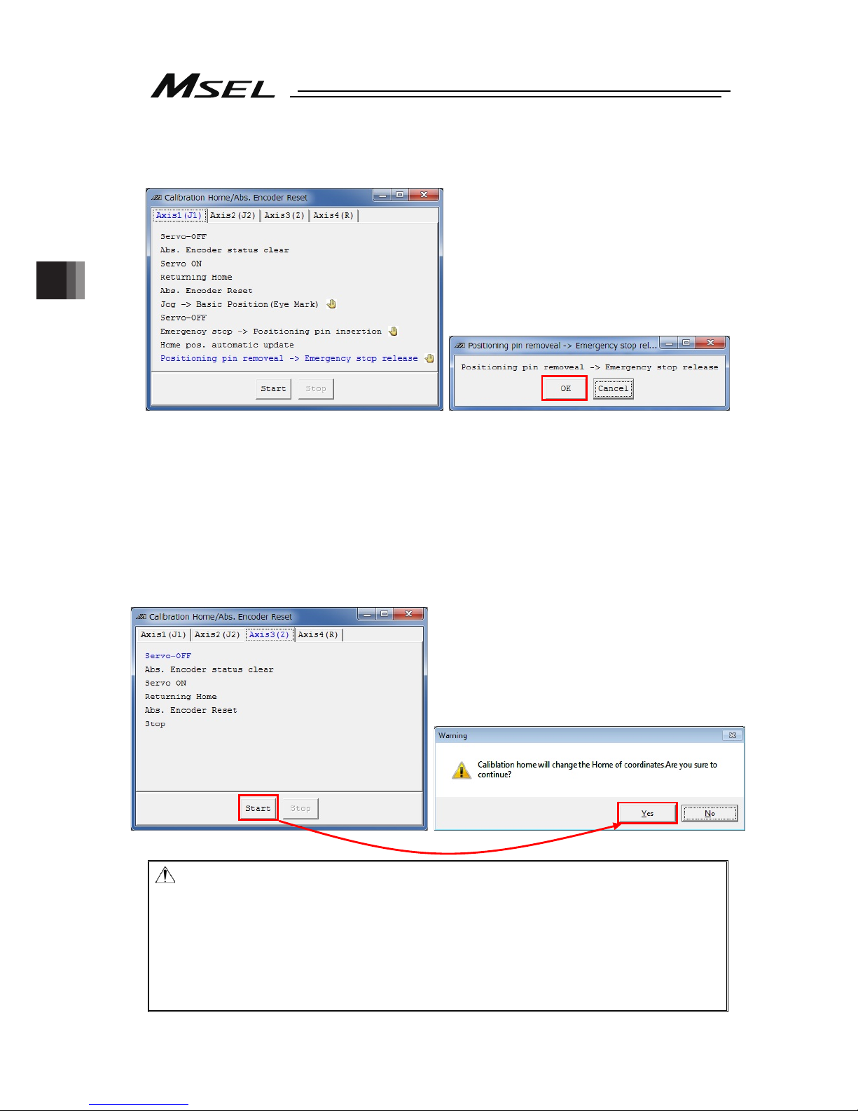
Chapter 4 Home-Return / Absolute Reset
86
10) Remove the home-position adjustment tool (φ4), and release the emergency stop. Click
“OK” in “Positioning Pin Ejection, Emergency Stop Release” window.
11) If absolute reset on both J1 and J2 Axes is not finished, go back to Step 5) to complete the
absolute reset on the remaining axes.
12) Conduct absolute reset on [Axis 3 (Z)].
Click on “Start” button while the [Axis 3 (Z)] tab is selected, and a warning window shows
up. Release the emergency stop, check the content and click “Yes”. Home-return
operation starts on the Z-axis.
Absolute reset completes after home return.
Caution: As soon as clicking “Yes”, the home-return operation starts. The standard home
position is the posture stated in the beginning of this section.
In case there is any interference to peripheral equipment during the home-return
operation, the home-return operation completes at the position of interference,
and the proper home position cannot be acquired. In such cases, it may cause a
crash or unexpected operation, which could cause malfunction or critical
operation error to the robot or the peripherals. Make sure to secure enough space
for home-return posture to avoid any interference to the peripherals during the
home-return operation.
Page 95

Chapter 4 Home-Return / Absolute Reset
87
13) Conduct absolute reset on [Axis 4 (R)].
Click on “Start” button while the [Axis 4 (R)] tab is selected, and a warning window shows
up.
Cancel the emergency stop and click “Yes”, and the home-return operation on the
selected axes starts.
14) “JOG -> Basic Position” window appears. Press “← (-)” and “→ (+)” buttons to move the
arm to a place near the datum position. [Refer to the figure in Step 15) for the datum
position]
Also, change “Jog Vel (JOG speed)” and “Inc. Distance (inching distance)” if necessary.
Click “OK” once the arm gets near the datum position.
Click “OK” when moving the arm new the datum position manually by hand.
Page 96

Chapter 4 Home-Return / Absolute Reset
88
15) Input the emergency stop, adjust it manually so it becomes the datum position for R Axis,
and insert the home-position adjusting tool (φ3). As shown in the figure below align the
position of either the D-cut surface on the R-axis tip or the D-cut surface on the hole for
insertion of the home-position adjustment tool (φ3).
Caution: Pay attention not to get the cables and pipes on the tool twisted.
16) With the home-position adjustment tool (φ4) being inserted, click “OK” in “Emergency stop
-> Positioning pin insertion” window.
Home-Position
Adjusting Tool (φ3)
D-cut Surface
Page 97

Chapter 4 Home-Return / Absolute Reset
89
17) Remove the home-position adjustment tool (φ3), and release the emergency stop. Click
“OK” in “Positioning pin removeal -> Emergency stop release” window.
18) After the adjustment on all the axes necessary to have an absolute reset is finished, close
“Calibration Home / Abs. Encoder Reset” window. After that, the window switches to
“Flash ROM Writing” window. Put a check mark on “Parameter” and click “Yes” to start
writing. After it is finished, conduct a software reset.
(Reference) After the absolute reset on each axis is finished, it is available to have the
flash ROM writing at once.
Page 98

Chapter 4 Home-Return / Absolute Reset
90
4.4 Simple Absolute Type (PC/PG/PCF/PGF Type Dedicated)
A Simple Absolute Type controller retains the position data of an encoder in battery backup. It
is not necessary to perform a home-return operation every time you turn it on.
To retain the encoder position data, it is necessary to register (absolute reset) the home
position.
It is available to check in the illuminating patterns on the status LED lamps for the drivers for
each axis whether it is necessary to conduct an absolute reset or not. Have an absolute reset
conducted when the status LED lamp for driver shows absolute reset is incomplete.
4.4.1 Status LED
It displays the status (condition) for absolute for each connected axis.
○: Illuminating, ×: OFF,
☆
: Flashing
4.4.2 Absolute Reset Preparation
Stated below is the procedure to conduct an absolute reset.
(In this manual, shows the procedure using the PC software. For handling and procedure on a
teaching pendant, refer to each instruction manual.)
1) For handling and procedure on a teaching pendant, refer to each instruction manual.
[Refer to Chapter 1 or Chapter 2]
2) Turn ON the power to the controller and connect the PC software.
3) Follow the section of the procedure for absolute to perform a reset.
Name
Lamp
condition
Color Description
○ Green Battery fully charged
○ Orange Battery in charge
0
○ Red Battery not connected
Name
Lamp Condition
of 1 (Color)
Lamp Condition
of 2 (Color)
Description
○ (Green) ○ (Green) Absolute Reset Complete
○ (Red) ○ (Green) Absolute Reset Incomplete
1,2
- ○ (Red) Alarm
Page 99

Chapter 4 Home-Return / Absolute Reset
91
4.4.3 Simple Absolute Type
Absolute batteries and absolute battery box are enclosed in a simple absolute type controller.
For an absolute battery, there is a specific position for each axis number. Refer to the figure
below to insert the batteries to the absolute battery box. There is also a position for connector
insertion specified for battery cables. Refer to the figure below to establish the connections.
z Front View after Absolute Battery Unit Cover Removed
Not to use
AX3
AX7
AX1
AX4AX5AX6AX7
AX3AX2 AX1AX0
AX4
AX6
AX0
AX2
AX5
Not to use
Not to use
1
s
t
battery
(Axis No.0)
3
r
d
battery
(Axis No.2)
Not to use
Not to use
2
n
d
battery
(Axis No.1)
4th battery
(Axis No.3)
Connector for
connection to
MSEL
4th axis (Axis No.3)
Position for
Connector Insertion
for Battery Cable
3
r
d
axis (Axis No.2)
Position for
Connector Insertion
for Battery Cable
2
n
d
axis (Axis No.1)
Position for
Connector Insertion
for Battery Cable
1
s
t
axis (Axis No.0)
Position for
Connector Insertion
for Battery Cable
Page 100
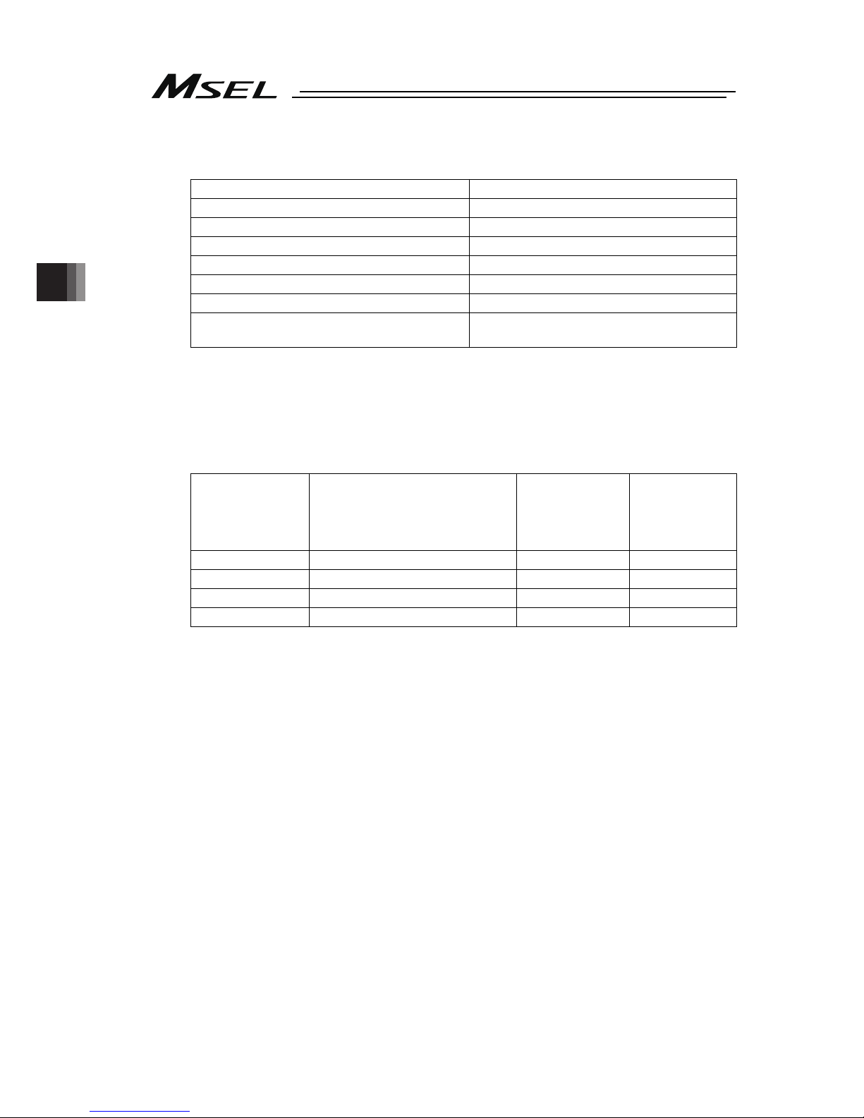
Chapter 4 Home-Return / Absolute Reset
92
4.4.4 Absolute Encoder Backup Type
Item Specification
Battery model AB-7
Number of Units 1 unit/axis (4 units/4 axes max.)
Battery Voltage 3.6V
Current Capacity 3300mAH
Reference for battery replacing timing
(Note 1)
Approx. 3 years (It may differ depending on
condition of use)
Note 1 Replace the battery regularly.
4.4.5 Charging Absolute Battery
Have the battery charged continuously for 72 hours or more for the first time to use or after
replacing the battery. While 24V is being supplied to a controller, battery is being charged.
Data Retaining Duration (Reference assuming a battery is new)
Setting in Each
Axis Parameter
No. 49
Upper Boundary for Number of
Encoder Rotation When Power is
off [rpm]
Reference for
Duration of
Battery
Remaining [days]
Retaining
Duration as of 1
Hour of Battery
Charging
(Reference) [hrs]
0 100 20 6.6
1 200 15 5.0
2 (factory default) 400 10 3.3
3 800 5 1.6
The data will be lost if the controller is off for more than the capable duration to retain the data.
Charge the battery as early as possible.
A battery has its life, and the capable duration to retain data decreases gradually. Replace the
battery if the retaining duration is remarkably dropped even after charging it properly.
e.g.) Conditions of Use;
Monday to Friday = Charged for 8 hours per day, discharged for 16 hours
Saturday and Sunday = Discharge
1) If setting is Parameter No. 19 = 3;
Total Charging: Operation time 8 [hrs] per day * Retaining time 1.6 [hrs] per hour of
charging * Weekdays 5 [days] = 64 [hrs]
Total Discharging: Stopped time during night 16 [hrs] * Weekdays 5 [days] + Stopped time
in weekend 48 [hours] = 128 [hrs]
Assuming to start on Monday with the battery fully charged, the total discharging exceeds
the total charging by 64 [hrs], thus the amount of fully charged keeps decreasing by 64
[hrs].
2) If setting is Parameter No. 19 = 2;
Total Charging: Operation time 8 [hrs] per day * Retaining time 3.3 [hrs] per hour of
charging * Weekdays 5 [days] = 132 [hrs]
Total Discharging: Stopped time during night 16 [hrs] * Weekdays 5 [days] + Stopped time
in weekend 48 [hours] = 128 [hrs]
Assuming to start on Monday, the total charging exceeds the total discharging, thus there
is no need of continuous full charging. The battery is charged for 4 hours in one week.
 Loading...