

Page 1

Thank you for purchasing this product.
Be sure to read this manual before use.
This manual includes important safety precautions and instructions on
how to operate the unit. Be sure to read this manual to ensure proper
operation.
© 2017 JAI
User Manual
GO-2400M-USB
GO-2400C-USB
2.35M Digital Progressive Scan
Monochrome and Color Camera
Document Version: 1.0
GO-2400-USB_Ver.1.0_Mar.2017
Page 2

Contents
Notice ............................................................................3
Warranty .......................................................................3
Certifications ................................................................. 3
Warning ........................................................................3
Usage Precautions .......................................................6
Features ........................................................................7
Parts Identification ........................................................8
Preparation........................................................... 11
Preparation Process ...................................................11
Step 1: Installing the Software (first time only) ............11
Step 2: Connecting Devices ........................................ 12
Step 3: Verifying the Camera’s Network Connection
Status ..........................................................................14
Step 4: Configuring Initial Settings for the Camera .....14
Connecting to the Camera to Control Tool .............14
Configuring the Output Format ...............................15
Configuring Exposure and External Trigger
Settings ...................................................................16
Control via External Triggers .......................................17
When Controlling the Exposure Time Using
Specified Exposure Times ......................................17
When Controlling the Exposure Time using
the Pulse Width of the Trigger Input Signal ............17
Control Without External Triggers ...............................18
When Controlling the Exposure Time Using
Specified Exposure Times ......................................18
When not Controlling the Exposure Time ...............19
Step 5: Adjusting the Image Quality............................19
Adjusting the Gain ..................................................19
Manual adjustment .............................................19
Adjusting the White Balance
(GO-2400C-USB only) ............................................20
Manual white balance adjustment ......................20
Automatic white balance adjustment .................20
Adjusting the Black Level .......................................20
Step 6: Configuring Various Other Settings ................20
Step 7: Saving the Settings .........................................20
To save user settings ..........................................21
To load user settings ...........................................22
Basic Function Matrix .................................................22
Main Functions .................................................... 23
GPIO (Digital Input/Output Settings) ...........................23
Valid Input/Output Combinations ............................23
Acquisition Control (Image Acquisition Controls) ........24
Changing the Frame Rate ......................................24
Maximum Frame Rate .............................................24
Maximum frame rate period formula ..................25
Exposure Mode ...........................................................26
Trigger Control ............................................................26
Shortest Repetition Period for Triggers ...................26
When [Exposure Mode] is [Timed] .....................27
When [Exposure Mode] is [Trigger Width] .........28
Gain Control ................................................................29
LUT (Lookup Table) ....................................................30
To use the LUT function ......................................30
LUT values ..........................................................30
Gamma Function ........................................................31
To use the gamma function ................................31
Defective Pixel Correction Function ............................ 31
Line Status ..................................................................31
Shading Correction .....................................................32
Flat Shading ........................................................32
Color Shading (GO-2400C-USB only) ................33
To use the shading correction function ..............33
Binning Function .........................................................33
ROI (Regional Scanning Function) .............................34
ROI Settings ............................................................34
Sensor Multi ROI Function ..........................................35
Sequencer Function ....................................................37
Delayed Readout [Acquisition Transfer Start] ........40
ALC (Automatic Level Control) Function ..................... 40
To use the ALC function ......................................40
Automatic gain level control ...............................40
Detailed Settings for Gain Auto
(Automatic Gain Level Control) ..............................41
Counter and Timer Control Function
(counter support only) ................................................. 42
Counter occurrence diagram .............................42
Internal camera blocks .......................................42
To use the counter function ................................43
Video Process Bypass Mode ......................................43
Differences in camera operation ........................43
To enable video process bypass mode..............43
Chunk Data Function ..................................................44
Configuring Chunk Data .....................................45
Settings List ......................................................... 46
Feature Properties ......................................................46
Miscellaneous ...................................................... 54
Troubleshooting ..........................................................54
Specifications ..............................................................55
Frame Rate Reference ...............................................57
Spectral Response .....................................................57
Dimensions .................................................................58
User’s Record .............................................................59
Index ..................................................................... 60
— 2 —
GO-2400M-USB / GO-2400C-USB
Page 3

— 3 —
Notice
The material contained in this manual consists of information that is proprietary to JAI Ltd., Japan and may
only be used by the purchasers of the product. JAI Ltd., Japan makes no warranty for the use of its product
and assumes no responsibility for any errors which may appear or for damages resulting from the use of the
information contained herein. JAI Ltd., Japan reserves the right to make changes without notice.
Company and product names mentioned in this manual are trademarks or registered trademarks of their
respective owners.
Warranty
For information about the warranty, please contact your factory representative.
Certifications
CE compliance
As defined by the Directive 2004/108/EC of the European Parliament and of the Council, EMC
(Electromagnetic compatibility), JAI Ltd., Japan declares that GO-2400M-USB and GO-2400C-USB comply
with the following provisions applying to its standards.
EN 61000-6-3 (Generic emission standard part 1)
EN 61000-6-2 (Generic immunity standard part 1)
FCC
This equipment has been tested and found to comply with the limits for a Class B digital device, pursuant
to Part 15 of the FCC Rules. These limits are designed to provide reasonable protection against harmful
interference in a residential installation. This equipment generates, uses and can radiate radio frequency
energy and, if not installed and used in accordance with the instructions, may cause harmful interference
to radio communications. However, there is no guarantee that interference will not occur in a particular
installation. If this equipment does cause harmful interference to radio or television reception, which can be
determined by turning the equipment off and on, the user is encouraged to try to correct the interference by
one or more of the following measures:
•Reorient or relocate the receiving antenna.
•Increase the separation between the equipment and receiver.
•Connect the equipment into an outlet on a circuit different from that to which the receiver is connected.
•Consult the dealer or an experienced radio/TV technician for help.
Warning
Changes or modifications to this unit not expressly approved by the party responsible for
FCC compliance could void the user
s authority to operate the equipment.
GO-2400M-USB / GO-2400C-USB
Page 4

— 4 —
GO-5000M-PGE
Supplement
The following statement is related to the regulation on “ Measures for the Administration
of the control of Pollution by Electronic Information Products “ , known as “ China RoHS “.
The table shows contained Hazardous Substances in this camera.
mark shows that the environment-friendly use period of contained Hazardous
Substances is 15 years.
嶷勣廣吭並㍻
嗤蕎嗤墾麗嵎賜圷殆兆各式根楚燕
功象嶄鯖繁酎慌才忽佚連恢匍何〆窮徨佚連恢瞳麟半陣崙砿尖一隈〇云恢瞳ゞ 嗤蕎嗤
墾麗嵎賜圷殆兆各式根楚燕 〃泌和
桟隠聞喘豚㍉
窮徨佚連恢瞳嶄根嗤議嗤蕎嗤墾麗嵎賜圷殆壓屎械聞喘議訳周和音氏窟伏翌
亶賜融延、窮徨佚連恢瞳喘薩聞喘乎窮徨佚連恢瞳音氏斤桟廠夛撹冢嶷麟半
賜斤児繁附、夏恢夛撹冢嶷鱒墾議豚㍉。
方忖仝15々葎豚㍉15定。
部件名称
有毒有害物质或元素
铅
(Pb)
汞
(Hg)
镉
(Cd)
六价铬
(Cr (VI))
多溴联苯
(PBB)
多溴二苯醚
(PBDE)
电路板 × ○ ○ ○ ○ ○
螺丝 × ○ ○ ○ ○ ○
插座 × ○ ○ ○ ○ ○
······ ······ ······ ······ ······ ······ ······
GO-2400M-USB / GO-2400C-USB
Page 5

— 5 —
GO-5000C-PGE
Supplement
The following statement is related to the regulation on “ Measures for the Administration
of the control of Pollution by Electronic Information Products “ , known as “ China RoHS “.
The table shows contained Hazardous Substances in this camera.
mark shows that the environment-friendly use period of contained Hazardous
Substances is 15 years.
嶷勣廣吭並㍻
嗤蕎嗤墾麗嵎賜圷殆兆各式根楚燕
功象嶄鯖繁酎慌才忽佚連恢匍何〆窮徨佚連恢瞳麟半陣崙砿尖一隈〇云恢瞳ゞ 嗤蕎嗤
墾麗嵎賜圷殆兆各式根楚燕 〃泌和
桟隠聞喘豚㍉
窮徨佚連恢瞳嶄根嗤議嗤蕎嗤墾麗嵎賜圷殆壓屎械聞喘議訳周和音氏窟伏翌
亶賜融延、窮徨佚連恢瞳喘薩聞喘乎窮徨佚連恢瞳音氏斤桟廠夛撹冢嶷麟半
賜斤児繁附、夏恢夛撹冢嶷鱒墾議豚㍉。
方忖仝15々葎豚㍉15定。
部件名称
有毒有害物质或元素
铅
(Pb)
汞
(Hg)
镉
(Cd)
六价铬
(Cr (VI))
多溴联苯
(PBB)
多溴二苯醚
(PBDE)
电路板 × ○ ○ ○ ○ ○
螺丝 × ○ ○ ○ ○ ○
插座 × ○ ○ ○ ○ ○
光学滤镜 × ○ × ○ ○ ○
······ ······ ······ ······ ······ ······ ······
GO-2400M-USB / GO-2400C-USB
Page 6

— 6 —
Notes on cable configurations
The presence of lighting equipment and television receivers nearby may result in video and audio
noise. In such cases, change the cable configurations or placement.
Notes on attaching the lens
Avoiding dust particles
When attaching the lens to the camera, stray dust and other particles may adhere to the sensor
surface and rear surface of the lens. Be careful of the following when attaching the lens.
•Work in a clean environment.
•Do not remove the caps from the camera and lens until immediately before you attach the lens.
•To prevent dust from adhering to surfaces, point the camera and lens downward and do not allow the
lens surface to come into contact with your hands or other objects.
•Always use a blower brush to remove any dust that adheres.
Never use your hands or cloth, blow with your mouth, or use other methods to remove dust.
Phenomena specific to CMOS image sensors
The following phenomena are known to occur on cameras equipped with CMOS image sensors. These
do not indicate malfunctions.
•
Aliasing
When shooting straight lines, stripes, and similar patterns, vertical aliasing (zigzag distortion) may
appear on the monitor.
•
Blooming
When strong light enters, more than the allowable amount of charge of the sensor element in the
CMOS image sensor (pixel) and the charge is overflowing, enters into the surrounding pixels, and
blooming may occur. However, this does not affect actual operation.
•
Fixed pattern noise
When shooting dark objects in high-temperature conditions, fixed pattern noise may occur
throughout the entire video monitor screen.
•
Defective pixels
Defective pixels (white and black pixels) of the CMOS image sensor are minimized at the factory
according to shipping standards. However, as this phenomenon can be affected by the ambient
temperature, camera settings (e.g., high sensitivity and long exposure), and other factors, be sure to
operate within the camera’s specified operating environment.
Notes on exportation
When exporting this product, please follow the export regulations of your country or region.
Usage Precautions
GO-2400M-USB / GO-2400C-USB
Page 7

— 7 —
GO-2400M-USB / GO-2400C-USB
Features
The GO-2400M-USB/GO-2400C-USB is an industrial progressive scan camera equipped with a
1/1.2-inch global shutter CMOS image sensor with 2.35 effective megapixels (1936 × 1216). The unit is
compact and lightweight in design and is equipped with USB 3.0 interface.
The GO-2400M-USB produces monochrome output while the GO-2400C-USB produces Bayer output.
Compact and lightweight
The unit’s compact (approx. 29 × 29 × 41.5 mm, excluding lens mount) and lightweight (approx. 46 g)
design allows for easy assembly and installation.
Output formats
You can choose from 8-bit, 10-bit, and 12-bit* output for both monochrome and Bayer.
* As the color camera cannot perform white balance when using 12-bit output, perform white balance on the
application.
High frame rate
The GO-2400M-USB and GO-2400C-USB are both capable of frame rates of up to 159 fps (8-bit
format) for full 2.35-megapixel output. Even faster frame rates can be achieved when a smaller ROI
(region of interest) is specified.
ALC (automatic level control) function
Combine the automatic gain control and automatic exposure control functions to allow handling of
changes in various brightnesses.
Variety of pre-process functions
• LUT (lookup table)
For programmable control over gamma and contrast.
• Gamma correction
Gamma can be set to 0.45, 0.60, or 1.0 (off).
• Shading correction (flat field and color shading)
Non-uniformity (i.e., shading) in the amount of light generated by the lens and lighting equipment can
be corrected.
• Bayer white balance (GO-2400C-USB only)
White balance can be automatically adjusted continuously. It can also be adjusted manually using R,
and B gain.
Connection example:
External trigger
AC adapter
Camera
Computer
USB 3.0
Page 8

— 8 —
GO-2400M-USB / GO-2400C-USB
Parts Identification
②
③
①
④
⑤
⑥
⑥
1
Lens mount (C-mount)
Mount a C-mount lens, microscope adapter, etc. here.
Before mounting a lens, be sure to refer to “Step 2: Connecting Devices” (page 12) and confirm the
precautions for attaching a lens and the supported lens types.
2
USB 3.0 connector
Use a USB 3.0 compatible cable to connect this to a USB port on the computer.
3
Power/trigger LED
Indicates the power and trigger input status.
LED status and camera status
LED Light Status
Power / trigger LED Lit amber Camera initializing.
Lit green Camera in operation.
Blinking green During operation in trigger mode, trigger signals are being
input.
The blinking interval is not related to the actual input interval
of the external trigger.
Page 9

— 9 —
GO-2400M-USB / GO-2400C-USB
4
DC IN / trigger IN connector (6-pin round)
Connect the cable for a power supply (optional) or for DC IN / trigger IN here.
1
2
3
4
5
6
HR-10A-7R-6PB (73) (Hirose Electric or equivalent)
Pin No.
Input/
output
Signal Description
1 DC IN +12 to +24 V±10%
2 In Opto IN 1
Line 5
3 Out Opto OUT 1
Line 2
4 Out Opto OUT 2
Line 3
5 Opto Common
6 GND
Recommended external input circuit diagram (reference example)
TLP2366
1
3
6
5
4
1SS400
180CS
BF545C
SD
G
IN
USER POWER1
+3.3V to +24V
JAI
GO Series CAMERA
side
User
side
+3.3V
JAI camera
HIROSE_6Pin_No.5
HIROSE_6Pin_No.2
User side
Page 10

— 10 —
GO-2400M-USB / GO-2400C-USB
Recommended external output circuit diagram (reference example)
Standard circuit diagram example
2SC6033
220BS
220BS
1SS400
180BS
100KBS
TLP109(TPR, E)
1
34
5
6
HIROSE_6Pin_No.5
HIROSE_6Pin_NO.3 or 4
OUT f rom cam era
USER POWER2
+5V to +24V
User
side
JAI
GO Series CAMERA
side
330
330~
2SC6033
4k7
OUT
4k7
Userload
(resistor/lamp/relay/etc)
JAI camera
User side
Characteristics of the recommended circuits for Opto OUT
OUTPUT LINE RESPONSE TIME
Output
Line
Voltage
Camera
Output
Signal
RT
TDR
TDF
FT
90%
10%
Output LEVEL = User Vcc- (0.8 to 1.1)
5
Camera locking screw holes (M3, 3 mm depth)
Use these holes when attaching an MP-43 tripod adapter plate (optional) or mounting the camera
directly to a wall or other structural system.
6
Camera locking screws (M3, 3 mm depth)
Use these when mounting the camera directly to a wall or other structural system.
Page 11

— 11 —
GO-2400M-USB / GO-2400C-USB
Preparation
Preparation Process
Step 1 Installing the Software (first time only)
Install the software for configuring and controlling the camera (JAI SDK) on the computer.
Step 2 Connecting Devices
Connect the lens, USB cable, AC adapter, computer, and other devices.
Step 3 Verifying Whether the Camera is Running
Verify whether the camera is ready for use.
Step 4 Configuring Initial Settings for the Camera
• Configure the output format.
• Configure settings related to the exposure and external trigger.
Step 5 Adjusting the Image Quality
• Adjust the gain and white balance.
• Adjust the exposure (shutter).
Step 6 Configuring Various Other Settings
Configure various other settings as necessary.
Step 7 Saving the Settings
Save the current setting configurations in user memory.
Step 1: Installing the Software (first time only)
When using the camera for the first time, install the software for configuring and controlling the camera
(JAI SDK) on the computer.
When you install JAI SDK, JAI Camera Control Tool will also be installed.
1
Download the “JAI - Getting Started Guide” and JAI SDK from the JAI website.
URL: http://www.jai.com/en/support/download-jai-software
2
Refer to the “JAI - Getting Started Guide,” and install JAI SDK on the computer.
The computer will restart when installation is complete.
Page 12

— 12 —
GO-2400M-USB / GO-2400C-USB
Step 2: Connecting Devices
Connect the lens, USB cable, AC adapter, and other devices.
Attach the lens in a clean environment to prevent dust from adhering to the unit.
Camera body
2
Direct connection
(or MP-43 tripod adapter plate)
5
DC IN / trigger IN
connection cable
1
Lens
3
USB cable
4
Computer
to external trigger
or
6
AC adapter (not supplied)
(power supply)
1
Lens
• C-mount lenses with lens mount protrusions of 9 mm or less can be attached.
9 mm or less
Lens mount protrusion
Lens
• The diagonal of the camera’s CMOS image sensor is 13.4 mm, which is larger than the 11 mm
size of standard 2/3-inch lenses. To prevent vignetting and to obtain the optimal resolution, use a
lens that will cover the 13.4 mm diagonal. Some lens manufacturers offer lenses with a 13.4 mm
format. If not, a 1-inch lens is recommended.
Page 13

— 13 —
GO-2400M-USB / GO-2400C-USB
Caution
• The maximum performance of the camera may not be realized depending on the lens.
• Attaching a lens with a mount protrusion of 9.1 mm or longer may damage the lens or camera.
Note
The following formula can be used to estimate the focal length.
focal length = WD / (1 + W/w)
WD: Working distance (distance between lens and object)
W: Width of object
w: Width of sensor (11.3 mm on this camera)
2
Direct connection (or MP-43 tripod adapter plate)
When mounting the camera directly to a wall or other device, use screws that match the camera
locking screw holes on the camera. (Large: M3, small: M2, depth: 3 mm)
Use the supplied screws to attach the tripod adapter plate.
Caution
For heavy lenses, be sure to support the lens itself. Do not use configurations in which its weight is supported
by the camera.
3
USB cable
Connect a USB cable to the USB 3.0 connector.
Caution
The camera is equipped with a USB 3.0 compatible Micro B connector. Although this connector includes USB
2.0 connectors, the camera does not support use of USB 2.0.
4
Computer
Use a computer that meets the following requirements.
Operating system (OS):
Microsoft Windows 7/8 32-bit/64-bit edition
CPU: Intel Core i3 or higher
Memory:
Windows 7/8 32-bit edition: DDR3, 4 GB or higher
Windows 7/8 64-bit edition: DDR3, 8 GB or higher
Graphics card: PCI-Express 3.0 or higher
Interface: USB 3.0 compatible connector
5
DC IN / trigger IN connection cable
6
AC adapter (power supply) (if necessary)
Connect the AC adapter and the round connector of the connection cable to the DC IN / trigger IN
connector on the camera.
Page 14

— 14 —
GO-2400M-USB / GO-2400C-USB
Step 3: Verifying the Camera’s Network Connection Status
When power is supplied to the camera while the necessary equipment is connected, the power /
trigger LED at the rear of the camera lights amber, and initialization of the camera starts.
When initialization is complete, the power / trigger LED lights green.
Verify whether power is being supplied to the camera by checking the rear LED.
Lit green
During normal status
For details on how to read the LEDs, see “LED status and camera status” (page 8) in the “Parts
Identification” section.
Step 4: Configuring Initial Settings for the Camera
Start Control Tool, configure initial settings for the output format, exposure, external trigger, etc.
Connecting to the Camera to Control Tool
1
Start JAI Control Tool.
Cameras connected to the computer’s USB 3.0 connectors are detected, and a window appears.
If they do not appear, right-click inside the window and select [Search for Cameras].
2
Select the camera you want to configure.
3
Check that the settings of the selected camera are displayed.
Page 15

— 15 —
GO-2400M-USB / GO-2400C-USB
Configuring the Output Format
Configure the size, position, and pixel format of the images to be acquired.
The factory settings are as follows. Change the settings as necessary.
Factory default values
Item Default value
Image Format Control Width 1936 (pixels)
Height 1216 (pixels)
Offset X (horizontal position) 0 (pixels)
Offset Y (vertical position) 0 (pixels)
Pixel Format GO-2400M-USB: 8 Bit Monochrome
GO-2400C-USB: 8 Bit Bayer RG
You can specify the image acquisition area. For details, see “ROI (Regional Scanning Function)” (page 34).
1
Select the [Feature Properties] tab, and select the item you want to configure under [Image
Format Control].
when a configurable item is selected.
Note
Settings can only be changed when image acquisition on the camera is stopped. If an item is grayed out and
does not appear even when you select it, click (Stop Acquisition) to stop image acquisition.
2
Click and change the setting value.
Example: When changing [Width]
Page 16

— 16 —
GO-2400M-USB / GO-2400C-USB
Example: When changing [Pixel Format]
Note
Direct entry of numerical and text values is possible for some setting items.
Configuring Exposure and External Trigger Settings
Configure settings related to exposure control methods and trigger control.
The factory settings are as follows. Change settings as necessary, according to the intended purpose
or application.
Factory default values
Item Default value
Trigger Selector (trigger operation) Frame Start
Trigger Mode Off
Trigger Source (trigger signal source) Line 5 - Optical In 1
Trigger Activation (trigger polarity) Rising Edge (rising edge of input signal)
Exposure Mode Timed (control via exposure time)
Exposure Time 6210 (µs)
Exposure Auto* Off
* This item is only enabled when [Exposure Mode] is set to [Timed].
Caution
When [Exposure Mode] is set to [Off], [Trigger Mode] cannot be set to [On]. Other settings may also be restricted
depending on the exposure mode, so be sure to set the exposure mode before configuring the trigger settings.
Configure the settings by expanding [Acquisition Control] and configuring the following items.
Caution
Settings can only be configured when image acquisition on the camera is stopped. If an item is grayed
out and the setting cannot be changed, stop image acquisition beforehand.
Page 17

— 17 —
GO-2400M-USB / GO-2400C-USB
Control via External Triggers
When Controlling the Exposure Time Using Specified Exposure Times
Configure the settings as follows.
Item Setting value / selectable range
Trigger Selector (trigger operation) Frame Start
Trigger Mode On
Trigger Source (trigger signal source) Any
Trigger Activation (trigger polarity) Rising Edge (rising edge of input signal), Falling Edge (falling
edge of input signal)
Exposure Mode Timed (control via exposure time)
Exposure Time 6 to 7999892 (µs) (1 µs/step)*
1
Exposure Auto Off, Continuous
* 1 The minimum value will differ depending on the [Pixel Format] setting value.
1
Set [Exposure Mode] to [Timed].
([Timed] is the default setting.)
2
Specify the exposure time in [Exposure Time].
The setting value for the exposure time can only be changed when [Exposure Auto] is set to [Off].
If [Exposure Auto] is set to [Continuous], temporarily set it to [Off] before changing the exposure
time.
3
Set [Trigger Selector] to [Frame Start].
([Frame Start] is the default setting.)
4
Set [Trigger Mode] to [On].
5
If necessary, change the [Trigger Source], [Trigger Activation], and [Exposure Auto]
settings.
When Controlling the Exposure Time using the Pulse Width of the Trigger Input Signal
Configure the settings as follows.
Item Setting value / selectable range
Trigger Selector (trigger operation) Frame Start
Trigger Mode On
Trigger Source (trigger signal source) Any
Trigger Activation (trigger polarity) Level High (high-level duration), Level Low (low-level
duration)
Exposure Mode Trigger Width (control via trigger width)
Page 18

— 18 —
GO-2400M-USB / GO-2400C-USB
1
Set [Exposure Mode] to [Trigger Width] .
When you select [Trigger Width], [Trigger Mode] will automatically be set to [On].
2
Set [Trigger Selector] to [Frame Start].
([Frame Start] is the default setting.)
3
If necessary, change the [Trigger Source] and [Trigger Activation] settings.
Other controls
In addition to exposure time, the following can also be controlled by external triggers. Select these
control operations in [Trigger Selector].
[Trigger Selector] setting Description
Acquisition Start Start image acquisition.
Acquisition End Stop image acquisition.
Acquisition Transfer Start Output acquired images at a specified timing. (Up to 8
frames for 8-bit, and up to 4 frames for 10-/12-bit.)
Control Without External Triggers
When Controlling the Exposure Time Using Specified Exposure Times
Configure the settings as follows.
Item Setting value / selectable range
Trigger Selector (trigger operation) Frame Start
Trigger Mode Off
Exposure Mode Timed (control via exposure time)
Exposure Time The exposure time will differ depending on the [Pixel Format]
and [Acquisition Frame Rate] setting values. (1 µs/step)*
1
Exposure Auto Off, Continuous
*1 The maximum value for [Exposure Time] varies depending on the value configured for the [Acquisition Frame
Rate Raw] setting.
Max. value for [Exposure Time] = [Acquisition Frame Rate Raw] value - 14H (8 bit: 14×4.85 = 67.9, 10/12 bit:
14×6.22 = 87.1)
1
Set [Exposure Mode] to [Timed].
([Timed] is the default setting.)
2
Specify the exposure time in [Exposure Time].
The setting value for the exposure time can only be changed when [Exposure Auto] is set to [Off].
If [Exposure Auto] is set to [Continuous], temporarily set it to [Off] before changing the exposure
time.
3
Set [Trigger Mode] to [On].
4
If necessary, change the [Exposure Auto] setting.
Page 19

— 19 —
GO-2400M-USB / GO-2400C-USB
When not Controlling the Exposure Time
Configure the settings as follows.
Item Setting value / selectable range
Exposure Mode Off
The exposure will be performed with an exposure time equal to 1 / frame rate.
Note
• [Exposure Time] will be disabled.
• [Exposure Auto] cannot be used.
Step 5: Adjusting the Image Quality
Adjust the image quality using the gain and white balance (GO-2400C-USB only) functions.
To adjust the image quality
The display level must be changed from [Beginner] to [Guru].
Adjusting the Gain
Adjust the sensitivity via the analog gain (i.e., master gain).
For details on gain control, see “Gain Control” (page 29) in the “Main Functions” section.
■ Manual adjustment
1
Expand [Analog Control], and set [Gain Auto] to [Off].
([Off] is the default setting.)
2
Configure the gain.
u
Expand [Analog Control], and select the gain you want to configure in [Gain Selector].
• For the GO-2400M-USB, only [Analog All] (master gain) can be configured.
• For the GO-2400C-USB, [Analog All] (master gain), [Digital Red] (digital R gain), and [Digital
Blue] (digital B gain) can be configured individually.
v
Configure the gain value in [Gain].
• [Analog All] (master gain) can be set to a value from x1 to x16 (0 dB to +24 dB). The
resolution is set in x0.01 steps (0.005 dB to 0.08 dB depending on the setting value). Values
are configured by multipliers.
• For the GO-2400C-USB, the [Digital Red] (digital R gain) and [Digital Blue] (digital B gain)
can be set to a value from x0.45 to x5.62 (–7 dB to +15 dB) the [Analog All] (master gain)
value. The resolution is set in x0.01 steps.
Page 20

— 20 —
GO-2400M-USB / GO-2400C-USB
Adjusting the White Balance (GO-2400C-USB only)
Adjust the white balance using R and B gain. The white balance can also be adjusted automatically.
■ Manual white balance adjustment
1
Expand [Analog Control], and set [Balance White Auto] to [Off].
([Off] is the default setting.)
2
Select the gain to configure in [Gain Selector], and set the gain value in [Gain].
■ Automatic white balance adjustment
1
Place a white sheet of paper or similar object under the same lighting conditions as the
intended subject, and zoom in to capture the white.
White objects near the subject, such as a white cloth or wall, can also be used.
Be sure to prevent the high-intensity spot lights from entering the screen.
2
Select the [Balance White Auto] tab, and click [Continuous] or [Once] depending on your
intended application.
The white balance is automatically adjusted.
Adjusting the Black Level
1
Expand [Analog Control], and select the black level you want to configure in [Black Level
Selector].
For the GO-2400M-USB, only [Digital All] (master black) can be configured.
For the GO-2400C-USB, [Digital All] (master black), [Digital Red] (digital R), and [Digital Blue]
(digital B) can be configured individually.
2
Specify the adjustment value in [Black Level].
Step 6: Configuring Various Other Settings
See “Settings List” (page 46) and configure settings as necessary.
Step 7: Saving the Settings
The setting values configured in Control Tool will be deleted when the camera is turned off. By saving
current setting values to user memory, you can load and recall them whenever necessary. You can
save up to three sets of user settings (User Set1 to 3) in the camera.
Page 21

— 21 —
GO-2400M-USB / GO-2400C-USB
User memory Temporary memory
Current
setting
values
Control Tool
Save
User Set1
User Set2
User Set3
Note
Changes to settings are not saved to the computer (Control Tool).
■ To save user settings
1
Stop image acquisition.
2
Expand [User Set Control], and select the save destination ([User Set1] to [User Set3]) in
[User Set Selector].
Note
The factory default setting values are stored in [Default] and cannot be overwritten.
Caution
Settings can only be saved when image acquisition on the camera is stopped.
3
Select [User Set Save], and click [Execute ‘User Set Save’ Command].
Page 22

— 22 —
GO-2400M-USB / GO-2400C-USB
The current setting values are saved as user settings.
■ To load user settings
1
Stop image acquisition.
User settings can only be loaded when image capture on the camera is stopped.
2
Select the settings to load (User Set1 to User Set3) in [User Set Selector].
3
Select [User Set Load], and click [Execute ‘User Set Load’ Command].
The selected user settings are loaded.
Basic Function Matrix
The combinations of settings for the basic functions that can be used together are as follows.
Exposure Mode
Frame Start Trigger
Binning Vertical*
1
Binning Horizontal*
1
Exposure Time
ROI
Balance White
Auto*
2
Gain Auto
Exposure Auto
Sequencer
Multi ROI
Sensor Multi ROI
Sensor
Trigger
Sequencer Mode
Command
Sequencer Mode
Off Off 1 × 1 (Off) ×
×
× ×
1 × 2 ×
×
×
× ×
2 × 1 ×
×
×
× ×
2 × 2 ×
×
×
× ×
Timed Off 1 × 1 (Off)
×
1 × 2
×
×
2 × 1
×
×
2 × 2
×
×
Timed (EPS) On 1 × 1 (Off)
1 × 2
×
2 × 1
×
2 × 2
×
Trigger Width On 1 × 1 (Off) ×
×
× ×
1 × 2 ×
×
×
× ×
2 × 1 ×
×
×
× ×
2 × 2 ×
×
×
× ×
*1 Operates only on the GO-2400M-USB
*2 Operates only on the GO-2400C-USB
Page 23

— 23 —
GO-2400M-USB / GO-2400C-USB
Main Functions
GPIO (Digital Input/Output Settings)
The camera is equipped with GPIO (general-purpose input/output) functions for generating and using
combinations of triggers and other necessary signals within the camera and of signals output from the
camera to the system such as those used for lighting equipment control.
Valid Input/Output Combinations
The following signals can be used as sources for each output destination (Trigger Selector, Line
Selector, Pulse Generator Selector).
You can also connect two different sources to NAND paths in the GPIO and reuse the signal generated
there as a source for a different selector.
The combinations of source signals and output destinations are indicated in the following.
Selector
(Cross point
switch output)
Source signal
(Cross point
switch input)
Output destination
Trigger Selector Line Selector
Acquisition Start
Acquisition End
Frame Start
Transfer Start
Line2 OPT Out 1
Line3 OPT Out 2
PG Clear
Time Stamp Reset
Nand Gate 0 In
Nand Gate 1 In
Signals to use as output
LOW
HIGH
User Output 0
User Output 1
Software
× × × × × ×
Pulse Generator 0
×
NAND 0 Out
×
NAND 1 Out
×
Line5-Optical In 1
FVAL
× × × ×
LVAL
× × × × × ×
Acquisition Trigger Wait
× × × ×
Frame Trigger Wait
× × × ×
Frame Active
× × × ×
Exposure Active
× × × ×
Trigger Source Line Source
Use
: Indicates default values for each selector. “Factory default values” (page 16) shows the
default values for [Frame Start].
Page 24

— 24 —
GO-2400M-USB / GO-2400C-USB
Acquisition Control (Image Acquisition Controls)
Perform operations and configure settings related to image acquisition in [Acquisition Control].
The following acquisition modes are available on the camera.
Acquisition Mode Description
Single Frame Acquire a single frame when the [Acquisition Start] command is executed.
Multi Frame Acquire the number of frames specified in [Acquisition Frame Count] when the
[Acquisition Start] command is executed.
Continuous Acquire images continuously until the [Acquisition Stop] command is executed.
Changing the Frame Rate
When [Trigger Mode] is disabled, you can change the frame rate in [Acquisition Frame Rate].
Note
• The shortest frame period varies depending on the ROI, pixel format, and binning mode selected. The longest
frame period is 0.125 Hz (8 sec.).
• When [Trigger Mode] is enabled, the [Acquisition Frame Rate] setting is disabled.
Maximum Frame Rate
The maximum frame rate is as follows depending on the sensor’s scanning range and the USB 3.0
bandwidth.
Maximum frame rate (A)
(Value derived from sensor
scanning range)
SensorFR
Compared
Maximum frame rate (B)
(Value derived from USB 3.0
bandwidth)
InterfaceFR
Maximum frame rate (A) Maximum frame rate (B)
(A) < (B) (A) > (B)
Page 25

— 25 —
GO-2400M-USB / GO-2400C-USB
■ Maximum frame rate period formula
During continuous operation ([Frame Start] trigger is [Off] or [Exposure Mode] is [Off])
• Maximum frame rate of sensor output
SensorFR = 1 / ((Height_s + 40) × Hperiod)
• Maximum frame rate of USB 3.0 output bandwidth
InterfaceFR = 3000 × 1000000 / (Height_g × Width_g × Pack value)
• Maximum frame rate
FR_Cont = Min (<SensorFR>, <InterfaceFR>)
When the exposure time is longer than the frame interval
• Maximum exposure time at maximum frame rate
MaxExposureTime_TrOlrd = (1 / FR_Cont) - (14 × H Period)
• Exposure time outside of frame interval
NonOverlapExposureTime = ExposureTime - MaxExposureTime_TrOlrd
However, NonOverlapExposureTime calculation results that are 0 or below will be considered as 0.
• Maximum frame rate
FR_ContLongExposure = 1/{(1/FR_Cont) + NonOverlapExposureTime}
When [Frame Start] trigger is [On] and [Trigger OverLap] is [Off]
• Maximum frame rate of sensor output
Sensor FR = 1 / {H Period × (Height + 40)}
• Maximum frame rate by interface
Interface FR = 3000 × 1000000 / (Height × Width × Pack value)
• Maximum frame rate
FR_Cont = Min (Sensor FR, Interface FR)
• Exposure time possible within frames
MaxOverlapTime_TrOloff = (1 / FR_Cont) - (1 / Sensor FR)
• Exposure time outside of frame interval
NonOverlapExposureTime_TrOloff = ExposureTime - MaxOverlapTime_TrOloff
However, NonOverlapExposureTime_TrOloff calculation results that are 0 or below will be
considered as 0.
For TriggerWidth, the trigger pulse is equivalent to ExposureTime.
• Maximum frame rate
FR_TrOloff = 1 / {(1 / FR_Cont) + NonOverlapExposureTime_TrOloff}
When [Frame Start] trigger is [On] and [Trigger OverLap] is [Readout]
• Maximum frame rate of sensor
Sensor FR = 1 / {H Period × (Height + 40)}
• Maximum frame rate by interface
Interface FR = 3000 × 1000000 / (Height × Width × Pack value)
• Maximum frame rate
FR_Cont = Min (Sensor FR, Interface FR)
• Exposure time possible within frames
MaxOverlapTime_TrOlrd = (1 / FR_Cont) - (14 × H Period)
• Exposure time outside of frame interval
NonOverlapExposureTime_TrOlrd = ExposureTime - MaxOverlapTime_TrOlrd
However, NonOverlapExposureTime_TrOlrd calculation results that are 0 or below will be considered
as 0.
For TriggerWidth, the trigger pulse is equivalent to ExposureTime.
• Maximum frame rate
FR_TrOlrd = 1 / {(1 / FR_Cont) + NonOverlapExposureTime_TrOlrd}
Page 26

— 26 —
GO-2400M-USB / GO-2400C-USB
Pixel Format
H Period (μs) Pack Value
8 bit
4.8485 8
10 bit packed
6.2222 10
12 bit packed
6.2222 12
10 bit/12 bit
6.2222 16
Exposure Mode
The following exposure modes are available on the camera.
Exposure Mode Description
Off Exposure control is not performed (free-running operation).
Timed Mode in which control is performed using exposure time. Acquire images using an
exposure time configured beforehand on an external trigger.
Trigger Width Mode in which control of the exposure time is performed using the pulse width of the
trigger input signal. The exposure time will be the same as the pulse width of the
trigger input signal. This allows long exposure.
The settings for exposure control and triggers are related to each other. Be sure to configure the settings
described in “Configuring Exposure and External Trigger Settings” (page 16).
Trigger Control
The camera allows the following controls to be performed via external trigger signals.
Trigger Selector Description
Frame Start Start exposure in response to the external trigger signal input. Select this to perform
exposure control using external triggers.
Acquisition Start Start image acquisition in response to the external trigger signal input.
Acquisition End Stop image acquisition in response to the external trigger signal input.
Acquisition Transfer Start Output acquired images at a specified timing in response to an external trigger
signal input. (Up to 8 frames for 8-bit, and up to 4 frames for 10-/12-bit.)
The settings for exposure control and triggers are related to each other. Be sure to configure the settings
described in “Configuring Exposure and External Trigger Settings” (page 16).
Shortest Repetition Period for Triggers
The reciprocal of the maximum frame rate is the time required to output one frame. The shortest
repetition periods for triggers cannot be lower than that value.
Scanning range
Shortest period of trigger
8 bit 10 bit Packed 10 bit
Full 6.289 ms 7.874 ms 12.658 ms
ROI 2/3 (Height = 810) 4.193 ms 5.249 ms 8.439 ms
ROI 1/2 (Height = 608) 3.145 ms 3.937 ms 6.329 ms
ROI 1/4 (Height = 304) 1.572 ms 1.969 ms 3.165 ms
ROI 1/8 (Height = 152) 0.786 ms 0.984 ms 1.582 ms
Binning Vertical 2* 3.145 ms 5.249 ms 8.439 ms
* GO-2400M-USB only
The above table indicates the shortest trigger periods for when [Trigger OverLap] is set to [Readout].
When [Trigger OverLap] is set to [Off], the exposure time is added to the period.
Page 27
— 27 —
GO-2400M-USB / GO-2400C-USB
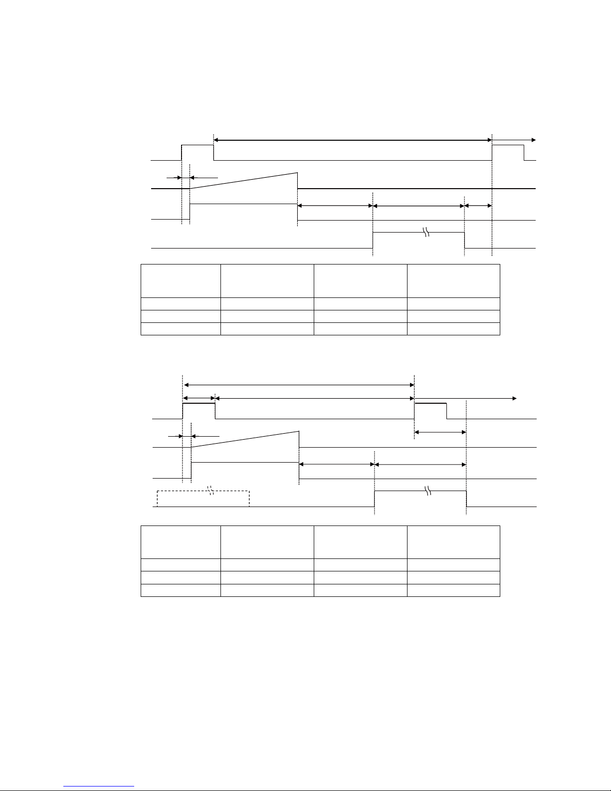
■ When [Exposure Mode] is [Timed]
Example: When [Trigger Source] is set to [Line 5 - Optical In 1] and [OptIn Filter Selector] is set to
[10 µs]
• Trigger overlap: Off
FVAL
データ出力期間
次のトリガ無効
次のトリガ
入力可能
Sensor
Exposure
Trigger
(= Height x Line Period)
EEN
A
B
C
Readout duration
Next trigger disabled
Next trigger
input enabled
Pixel format Period from Trigger
start edge to Exposure
start[A](usec)
Period from Exposure
end to FVAL start[B]
(usec)
Period FVAL end to
next trigger start[C]
(usec)
8 bit 422 165 355
10 bit packed 26 212 41
10 bit 26 212 4749
• Trigger overlap: Readout
FVAL
Sensor
Exposure
Trigger
(= Height x Line Period)
EEN
A
B
C
Readout duration
Next trigger disabled
Next trigger
input enabled
Pixel format Period from Trigger
start edge to Exposure
start[A](usec)
Period from Exposure
end to FVAL start[B]
(usec)
Period FVAL end to
next trigger start[C]
(usec)
8 bit 422 165 6277-ExposureTime
10 bit packed 26 212 7848-ExposureTime
10 bit 26 212 12556-ExposureTime
Page 28
— 28 —
GO-2400M-USB / GO-2400C-USB
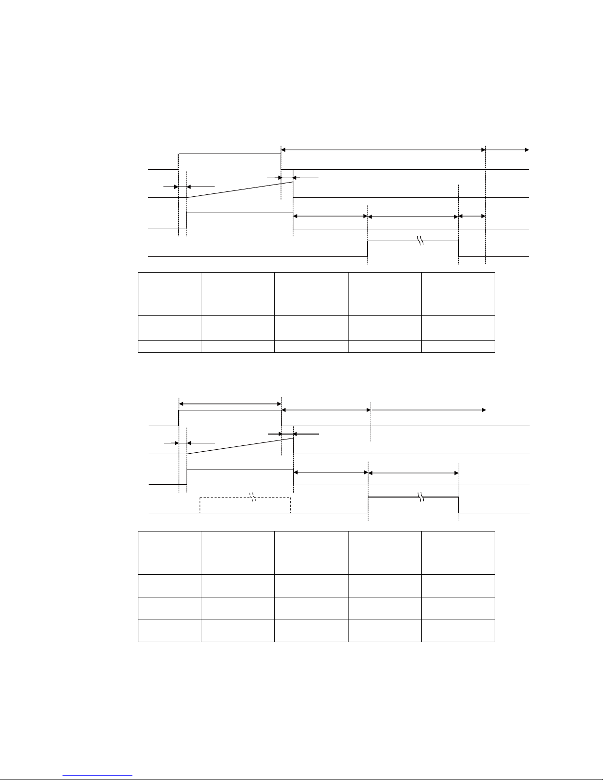
■ When [Exposure Mode] is [Trigger Width]
Example: When [Trigger Source] is set to [Line 5 - Optical In 1] and [OptIn Filter Selector] is set to
[10 µs]
• Trigger overlap: Off
FVAL
データ出力期間
次のトリガ無効
次のトリガ
入力可能
Sensor
Exposure
Trigger
(= Height x Line Period)
EEN
A
B
C
D
Readout duration
Next trigger disabled
Next trigger
input enabled
Pixel format Period from
Trigger start edge
to Exposure
start[A](usec)
Period from
Exposure end to
FVAL start[B]
(usec)
Period FVAL end
to next trigger
start[C](usec)
Period from
Trigger end edge
to Exposure
end[D](usec)
8 bit 422 165 355 22
10 bit packed 26 212 41 26
10 bit 26 212 4749 26
• Trigger overlap: Off
FVAL
Sensor
Exposure
Trigger
(= Height x Line Period)
EEN
A
B
D
C
Readout duration
Next trigger
disabled
Next trigger input enabled
Pixel format Period from
Trigger start edge
to Exposure
start[A](usec)
Period from
Exposure end to
FVAL start[B]
(usec)
Next trigger start
prohibited
period[C](usec)
Period from
Trigger end edge
to Exposure
end[D](usec)
8 bit 422 165 67.879
(14*Line Period)
22
10 bit packed 26 212 87.1108
(14*Line Period)
26
10 bit 26 212 87.1108
(14*Line Period)
26
Page 29
— 29 —
GO-2400M-USB / GO-2400C-USB
Gain Control
[Analog All] can be used for gain control for both the monochrome and color camera. [Analog All]
(master gain) uses the sensor's internal gain function and consists of analog gain + digital gain.
Analog gain is used for lower gain, and analog gain + digital gain is used when the gain becomes
high. R and B can be configured individually as digital gain on the GO-2400C-USB.
For details on how to configure the settings, see “Adjusting the Gain” (page 19).
The relationship between the gain setting value, gain amplification, and dB value is as follows. For
example, a gain amplification of x5.62 will be 15 dB.
Monochrome
x16
x1
16.0
1.0
24dB
0dB
Gain
setting
value
Gain
amplification
Gain adjustment range (monochrome)
Bayer color
X89.12
X16
X7.15
X5.62
X1
X0.45
16.0
1.0
37876 (X5.62)
0 (X1)
–4533 (X0.45)
R&B
Red
Blue
39dB
-7dB
0dB
24dB
15dB
0dB
–7dB
15dB
0dB
–7dB
15dB
37876 (X5.62)
0 (X1)
–4533 (X0.45)
Gain
setting
value
Master Master
Gain
amplification
Gain setting
value (scaling)
Gain adjustment range (Bayer color)
Page 30

— 30 —
GO-2400M-USB / GO-2400C-USB
LUT (Lookup Table)
The LUT function is used to generate a non-linear mapping between signal values captured on the
sensor and those that are output from the camera. You can specify the output curve using 257 setting
points (indexes).
■ To use the LUT function
Configure the settings as follows.
Item Setting value / selectable range Description
JAI LUT Mode LUT Use LUT.
LUT Selector* R, G, B Select the LUT channel to control.
LUT Index GO-2400M-USB: 0 to 256
GO-2400C-USB: 0 to 256
Select the LUT index to configure. Indexes represent the
possible pixel values captured on the sensor, from the lowest
value (Index 0) to the highest (Index 256). For example,
Index 0 represents a full black pixel and Index 256
represents a full white pixel.
LUT Value 0 to 4095 Set the LUT output value for the selected index.
* GO-2400C-USB only
■ LUT values
LUT values range from 0 at the lowest to 4095 at the highest. Linear interpolation is used to calculate
LUT values between the index points.
4095
Index0
Index1
LUT Value [1]
LUT Value [0]
Index256
Values between points are determined
using the linear interpolation values of data
to the left and right.
Page 31
— 31 —
GO-2400M-USB / GO-2400C-USB
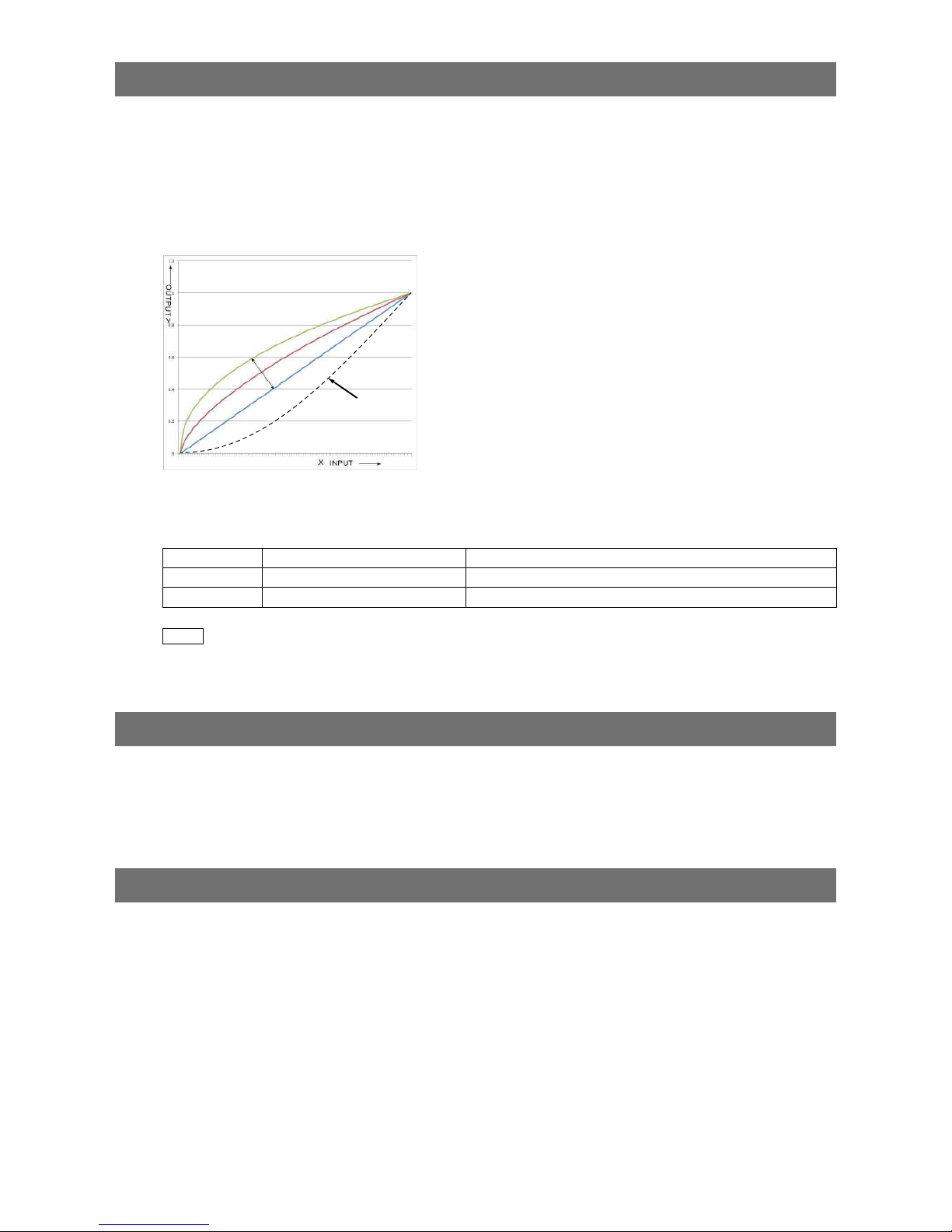
Gamma Function
The gamma function corrects the output signals from the camera beforehand (reverse correction),
taking into consideration the light-emitting properties of the monitor display.
As the light-emitting properties of the monitor are not linear, the entire image may be darker or the
gradation in the dark areas may be less noticeable when camera outputs are displayed without
processing.
The gamma function can be used to correct the camera signals with an opposite-direction curve and
produce a display that is close to linear.
Example of the light-emitting properties
of the monitor display
■ To use the gamma function
Configure the settings as follows.
Item Setting value / selectable range Description
Gamma 0.45, 0.60, 1.0 (Off) Select the gamma correction value.
JAI LUT Mode Gamma Use gamma.
Note
You can use the LUT function to configure a curve with more detailed points. For details, see “LUT (Lookup Table)”
(page 30).
Defective Pixel Correction Function
Multiple defective pixels that are not adjacent to each other can occur on conventional CMOS sensor
cameras.
This camera features a function that interpolates defective pixels using the surrounding pixels.
Up to 256 pixels can be corrected.
Line Status
The line status function allows you to verify the status of external input/output signals.
You can verify the status of the following signals.
•Opt Out 1, Opt Out 2, Opt In 1
•Time Stamp Reset
•NAND Gate 0 In 1, NAND Gate 0 In 2, NAND Gate 1 In 1, NAND Gate 1 In 2
Page 32

— 32 —
GO-2400M-USB / GO-2400C-USB
Shading Correction
The shading correction is a function that corrects non-uniformity (i.e., shading) in the amount of light
generated by the lens and lighting equipment. Using this function allows correction even if top, bottom,
left, and right shading is not symmetrical in relation to the center of the screen (H, V).
The size of the correction block is 16 (H) × 10 (V) blocks and calculation errors in the correction data
are minimized due to the small interpolation block. Each block is 128 × 128 pixels.
The total size of the blocks is 2048 (H) × 1280 (V), but the actual number of effective pixels for the
camera is 1936 (H) × 1216 (V). The ineffective peripheral areas will be deleted internally on the camera
automatically.
2048 (Total size)
1936 (Effective pixels)
1280 (Total size)
1216 (Effective pixels)
128
128
to
to
The following shading correction modes are available on the camera. However, as proper interpolation
is not performed when ROI settings are configured, execute shading correction at full size before
configuring the ROI settings.
■ Flat Shading
Correction is performed using the area of the screen with the highest brightness level as the reference,
and adjusting the brightness levels of the other areas to match this level.
Within 30% of
adjustment range
Page 33

— 33 —
GO-2400M-USB / GO-2400C-USB
■ Color Shading (GO-2400C-USB only)
R-channel and B-channel properties are adjusted to using the G-channel shading properties as a
reference.
Pre-correction Post-correction
Caution
Proper correction is not possible under the following conditions.
• If an area with a brightness level that is more than 30% less than the reference level exists within the
screen
• If the brightness level is saturated in parts or all of the screen
• If the area in the screen with the highest brightness level is 300 LSB or less (during 10-bit video
output)
■ To use the shading correction function
Configure the settings as follows.
Item Setting value Description
Shading Correction Mode GO-2400M-USB:
Flat Shading (fixed)
GO-2400C-USB:
Flat Shading, Color Shading
Select the shading correction mode.
Shading Mode User 1, User 2, User 3, Off Select the user area to which to save the
shading correction value.
Display a white chart under a uniform light, and execute [Perform Shading Calibration].
Note
After shading correction is executed, the shading correction value is automatically saved to the user area selected
in [Shading Mode].
Binning Function
The binning function (GO-2400M-USB Only) allows you to combine the signal values of clusters of
adjacent pixels on the sensor to create improved virtual pixels. Using the function results in images with
lower pixel resolution and higher sensitivity.
Common methods of binning include “horizontal binning” where two horizontally adjacent pixels are
combined, and “vertical binning” where two vertically adjacent pixels are combined. By combining the
horizontal and vertical methods to create a group of four pixels (2×2 binning), you can create images
with x4 sensitivity.
Page 34

— 34 —
GO-2400M-USB / GO-2400C-USB
ROI (Regional Scanning Function)
The ROI (region of interest) function allows you to output images by specifying the areas to scan.
ROI Settings
Specify the area to scan by specifying width, height, and horizontal/vertical offset values under [Image
Format Control].
For details on how to configure the settings, see “Configuring the Output Format” (page 15).
You can increase the frame rate by specifying a lower height, as the number of lines scanned
decreases.
The minimum area is as follows.
Minimum width value (pixels) Minimum height value (pixels)
GO-2400M-USB 16 1
GO-2400C-USB 16 2
Example 1: Without binning
[Binning Horizontal] *: 1
[Binning Vertical] *: 1
OffsetX
OffsetY
Height
Width
1216 Height Max
1936 Width Max
Scanning range
Example 2: With binning
[Binning Horizontal] *: 2
[Binning Vertical] *: 2
OffsetX
OffsetY
Height
Width
608 Height Max
968 Width Max
Scanning range
* GO-2400M-USB only
For details on the frame rates for common ROI sizes, see “Frame Rate Reference” (page 57).
Page 35

— 35 —
GO-2400M-USB / GO-2400C-USB
Sensor Multi ROI Function
Sensor Multi ROI is an ROI function that is configured and functions inside the sensor.
You can configure up to 16 scanning regions (4 horizontal and 4 vertical).
By skipping areas that are not specified as regions of interest when scanning a frame, the sensor's ROI
function outputs the specified regions in a compressed state. You can increase the frame rate due to
the reduced scanning time for the compressed areas. However, you cannot make the line frequency
faster by compressing in the horizontal direction.
ROI 1-1
ROI 1-2
ROI 1-3
ROI 1-4
ROI 2-1
ROI 3-1
ROI 4-1
ROI 2-2 ROI 2-3
ROI 2-4
ROI 3-4
ROI 3-3
ROI 4-2
ROI 4-4
ROI 3-2
ROI 4-3
ROI 1-1 ROI 1-2
ROI 1-3
ROI 1-4
ROI 2-1
ROI 3-1
ROI 4-1
ROI 2-2 ROI 2-3
ROI 2-4
ROI 3-4
ROI 3-3
ROI 4-2
ROI 4-4
ROI 3-2
ROI 4-3
Total sensor area (1936 × 1216)
The areas selected with the ROI function
will be compressed.
Horizontal pixel count
ROI Width 1 + ROI Width 2 +
ROI Width 3 + ROI Width 4
Vertical pixel count
ROI Height 1 + ROI Height 2 +
ROI Height 3 + ROI Height 4
Restrictions
• The specified areas cannot overlap.
• The frame rate can be increased in relation to size of the area specified in the vertical direction, but
not in relation to the horizontal direction.
• In the horizontal direction, the configuration for the second and subsequent row will be identical. In
the vertical direction, the configuration for the second and subsequent column will be identical.
Configuration
Configure each area so that they do not overlap.
Both the horizontal and vertical settings must be configured as even values.
Horizontal ROI conditions
ROI Offset H1 + ROI Width 1 < ROI Offset H2
ROI Offset H2 + ROI Width 2 < ROI Offset H3
ROI Offset H3 + ROI Width 3 < ROI Offset H4
ROI Offset H4 + ROI Width 4 < 1936
Vertical ROI conditions
ROI Offset V1 + ROI Height 1 < ROI Offset V2
ROI Offset V2 + ROI Height 2 < ROI Offset V3
ROI Offset V3 + ROI Height 3 < ROI Offset V4
ROI Offset V4 + ROI Height 4 < 1216
Configure the four index settings (Index 1 to 4). The [OffsetH], [Width], [OffsetV], [Height], [Horizontal
Enable], and [Vertical Enable] settings can be configured for each index.
Note
Sensor Multi ROI cannot be used together with Sequencer function (Page 37).
Page 36

— 36 —
GO-2400M-USB / GO-2400C-USB
When you configure the [OffsetH], [Width], [OffsetV], and [Height] settings for an index and set
[Horizontal Enable] or [Vertical Enable] to [True] for that index, the corresponding area is configured.
When [False] is specified, the settings within the index are disabled.
OffsetH, Width: 16 pixels/step
OffsetV, Height: 2 lines/step
ROI 1-1 ROI 1-2
ROI 1-3
ROI 1-4
ROI 2-1
ROI 3-1
ROI 4-1
ROI 2-2 ROI 2-3
ROI 2-4
ROI 3-4
ROI 3-3
ROI 4-2
ROI 4-4
ROI 3-2
ROI 4-3
Index1 Index2 Inde x3 Index4
Index1
Index2
Index3
Index4
Total sensor area (1936 × 1216)
Reference: Areas corresponding to the [Horizontal Enable] and [Vertical Enable] settings of each
setting
Index 1 Index 2 Index 3 Index 4 Number of
Enabled ROI
Enabled area
Hori Ver t Hori Vert Hori Vert Hori Vert
True True False False False False False False 1 ROI 1-1
True True True True False False False False 4 ROI 1-1, ROI 1-2, ROI 2-1, ROI 2-2
True True True False False False False False 2 ROI 1-1, ROI 1-2
True True True True True True False False 9 ROI 1-1, ROI 1-2, ROI 1-3
ROI 2-1, ROI 2-2, ROI 2-3
ROI 3-1, ROI 3-2, ROI 3-3
True True True True True True True False 12 ROI 1-1, ROI 1-2, ROI 1-3, ROI 1-4
ROI 2-1, ROI 2-2, ROI 2-3, ROI 2-4
ROI 3-1, ROI 3-2, ROI 3-3, ROI 3-4
True True True True True True True True 16 ROI 1-1, ROI 1-2, ROI 1-3, ROI 1-4
ROI 2-1, ROI 2-2, ROI 2-3, ROI 2-4
ROI 3-1, ROI 3-2, ROI 3-3, ROI 3-4
ROI 4-1, ROI 4-2, ROI 4-3, ROI 4-4
Frame rate calculation formula
FR + line frequency ÷ (ROI Height 1 + ROI Height 2 + ROI Height 3 + ROI Height 4 + vertical invalid
line)
There are two types of line frequencies.
SensorReadout 10 bit, camera output 8 bit: 12.4445 KHz
SensorReadout 12 bit, camera output 10 bit: 24.2425 KHz
Vertical invalid line: 40 (fixed)
Page 37

— 37 —
GO-2400M-USB / GO-2400C-USB
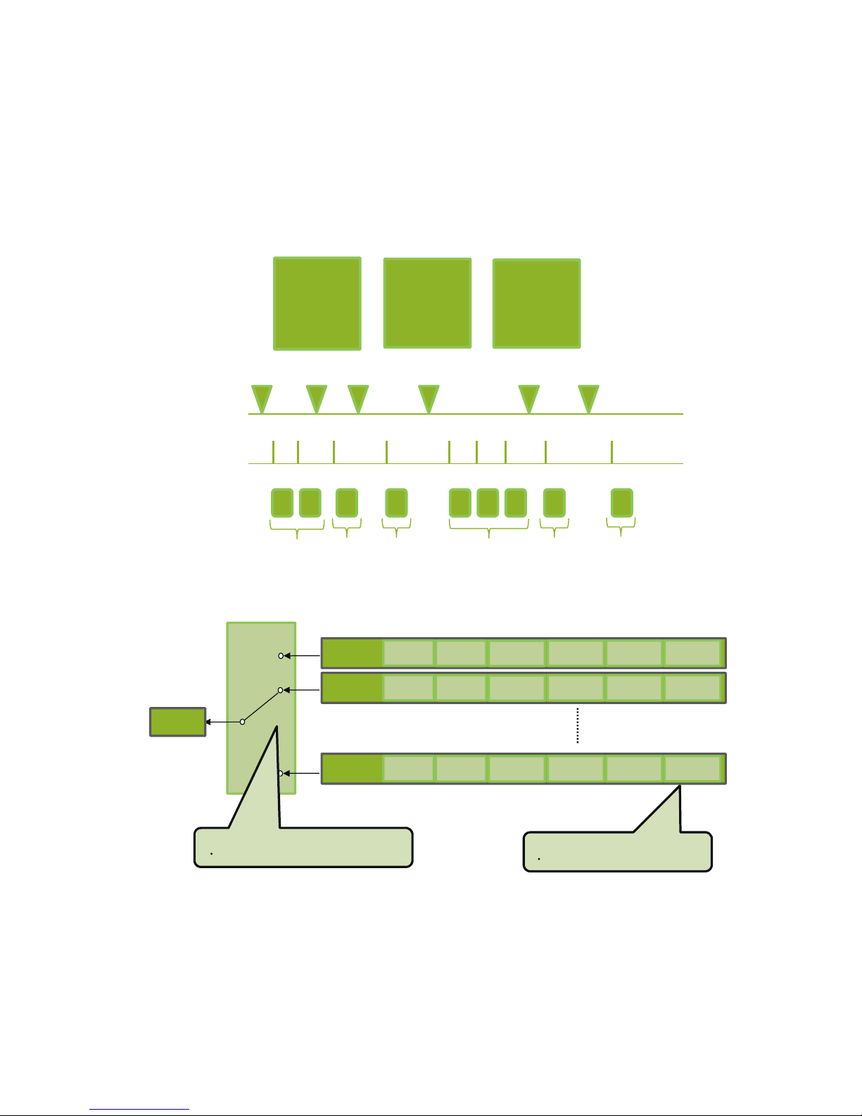
Sequencer Function
The Sequencer function lets you define up to 128 preset combinations of exposure time, gain, ROI, and
other settings which can be stepped through each time a trigger is received. This is particularly useful
for quickly capturing multiple exposures of objects under inspection to adjust for areas or components
with significantly different levels of reflectance. The order of execution and the repetition of particular
presets are based on user-defined parameters configured in [Sequencer Control].
Two operation modes (Trigger Sequencer mode and Command Sequencer mode) are available for the
Sequencer function.
Trigger Sequencer mode
With this mode, the Sequencer Trigger “pattern” is predetermined by the user. The user defines up to
128 different “indexes.” Each index represents a combination of the following parameters:
• ROI (width, height, offset X, and offset Y)
• Exposure Time
• Gain Level (R/B Gain can also be configured on the color model)
• Black Level
• Binning Mode (monochrome only)
• LUT Enable (whether or not to enable the use of LUT for this index)
• Frame Count (the number of times to repeat this index before moving to the next)
• Next Index to execute in the predetermined pattern
In addition to these individual index parameters, two other parameters are applied to the entire
sequence:
[Sequencer LUT Mode] defines whether Gamma or LUT is to be applied to the sequence. If Gamma
is selected, the Gamma setting defined in the camera’s Analog Control section will be applied to all
exposures in the sequence. If LUT is selected, the LUT characteristics defined in Analog Control will
be applied to any index where [Sequencer LUT enable] has been set to ON.
[Sequencer Reset] causes the index selector to be reset to Index 1. Thus, the sequencer pattern will
start over at the next trigger.
In Trigger Sequencer mode, patterns begin with the index of [Sequencer Set Start]. Subsequent
triggers follow the user-defined values in [Sequencer Index Frame Count] and [Sequencer ROI Next
Index].
Assigning a Next Index value of “1” to an index creates a loop back to the start of the sequencer
pattern. Setting a Next Index value to “OFF” causes the value of [Sequencer Repetition] to be applied
as described below.
[Sequencer Repetition]
This parameter applies to Trigger Sequencer patterns which include an index whose [Sequencer ROI
Next Index] is set to OFF.
When the index whose [Sequencer ROI Next Index] is set to OFF is finished executing, the value of
Sequencer Repetition (range = 1-255) is decremented internally. If the result of the decrement is not
zero, the Trigger Sequencer pattern starts over from Index1. If the result of the decrement is zero, the
status changes to Acquisition Stop and external triggers are not accepted.
Note
Sequencer function cannot be used together with Sensor Multi ROI function (Page 35).
Page 38

— 38 —
GO-2400M-USB / GO-2400C-USB
Trigger Sequencer example
User-defined Indexes (up to 128)
Index1 Index2
Index4 Index3
ROI
Exposure
Gain
LUT
Binning
Frame Count = 2
Next Index = 3
ROI
Exposure
Gain
LUT
Binning
Frame Count = 1
Next Index = 1
ROI
Exposure
Gain
LUT
Binning
Frame Count = 1
Next Index = 4
ROI
Exposure
Gain
LUT
Binning
Frame Count = 2
Next Index = 2
Triggers /
Image
Frames
Index structure for Trigger Sequencer
Index1
ROI1
Exposure
1
Gain1
(M/Red/Blue)
Black
Level1
Binning1
(H/V)
LUT
Enable1
Frame
Count1
Next
Index1
Index2
ROI2
Exposure
2
Gain2
(M/Red/Blue)
Black
Level2
Binning2
(H/V)
LUT
Enable2
Frame
Count2
Next
Index2
Index128 ROI128
Exposure
128
Gain128
(M/Red/Blue)
Black
Level128
Binning128
(H/V)
LUT
Enable128
Frame
Count128
Next
Index128
Index
Selector
(MUX)
Index Table
・
Index Next Index
Current
Index
Command
・
Reset Sequencer Index
Reset
Sequencer
Common Settings
・
Sequencer LUT mode
Command Sequencer mode
This mode allows the user to vary the “pattern” of the sequence in response to external factors.
Changes in the sequence can be initiated manually or in a programmatic fashion as the result of data
from sensors/controllers or from the analysis of previous images.
In this mode, the user can define up to 128 different “indexes” each incorporating a combination of:
• ROI (width, height, offset X, and offset Y)
• Exposure Time
• Gain Level (R/B Gain can also be configured on the color model)
• Black Level
• Binning Mode (monochrome only)
• LUT Enable (whether or not to enable the use of LUT for this index)
The user must also enter a value from 1 to 128 in [Command Sequencer Index]. This indicates which
index to execute each time a trigger is received. The same index will continue to be executed for all
subsequent triggers as long as the value of [Command Sequencer Index] remains unchanged.
Changing the value of [Command Sequencer Index] to one of the other predefined indexes causes
that index to be executed in response to subsequent triggers. This mode of operation enables users to
develop applications that continually send new values to [Command Sequencer Index] in response to
external factors such as changing light conditions, different types or sizes of objects being inspected,
or other factors. This allows applications to change ROI, exposure, gain, etc., without being restricted
to a predefined pattern.
Page 39
— 39 —
GO-2400M-USB / GO-2400C-USB
As with Trigger Sequencer, [Sequencer LUT Mode] defines whether Gamma or LUT is to be applied
to the sequence. If Gamma is selected, the Gamma setting defined in the camera’s Analog Control
section will be applied to all exposures in the sequence. If LUT is selected, the LUT characteristics
defined in Analog Control will be applied to any index where [Sequencer LUT enable] has been set to
ON.
[Sequencer Index Frame Count], [Sequencer ROI Next Index], and [Reset Sequencer Index] are not
used in Command Sequencer mode and entered values are ignored.
Command Sequencer Example
User-defined Indexes (up to 128)
Index1 Index2
Index3
ROI
Exposure
Gain
LUT
Binning
ROI
Exposure
Gain
LUT
Binning
ROI
Exposure
Gain
LUT
Binning
Command
Sequencer
Index
Camera
Triggers
Image
Frames
Set to
Index1
Set to
Index3
Set to
Index1
Set to
Index2
Set to
Index1
Set to
Index2
Index1
Settings
Index3
Settings
Index1
Settings
Index2
Settings
Index1
Settings
Index2
Settings
Settings
Used
Index structure for Command Sequencer
Index1
ROI1
Exposure1
Gain1
Black
Level1
Binning1
LUT
Enable1
Index2
ROI2
Exposure2
Gain2
Black
Level2
Binning2
LUT
Enable2
Index128
ROI128
Exposure
128
Gain128
Black
Level128
Binning128
LUT
Enable128
Index
Selector
(MUX)
Current
(M/Red/Blue)
(H/V)
(M/Red/Blue)
(H/V)
Common Settings
Command Sequencer Index (1 to 128)
Common Settings
Sequencer LUT mode
Index
(M/Red/Blue) (H/V)
Page 40
— 40 —
GO-2400M-USB / GO-2400C-USB
Delayed Readout [Acquisition Transfer Start]
Delayed readout enables images captured by a Frame Start trigger command to be stored inside
the camera and read out on demand at a later time using Acquisition Transfer Start trigger. This can
be especially useful when multiple cameras need to be triggered at the same time, but simultaneous
readout of all images would overwhelm the available network bandwidth. The delayed readout buffer
can hold up to 8 frames in 8-bit mode or 4 frames in 10-bit or 12-bit modes.
For details, see “Trigger Control” (page 26).
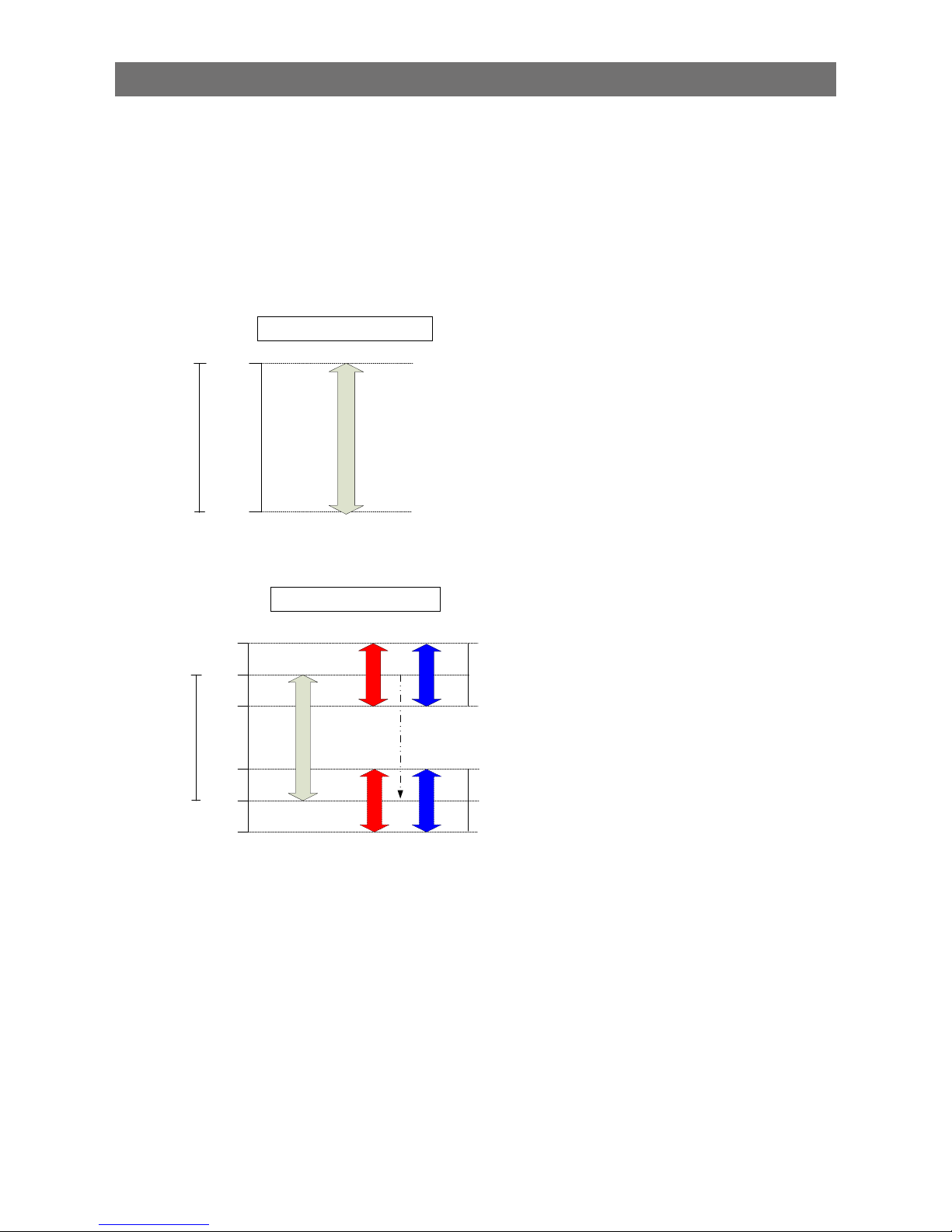
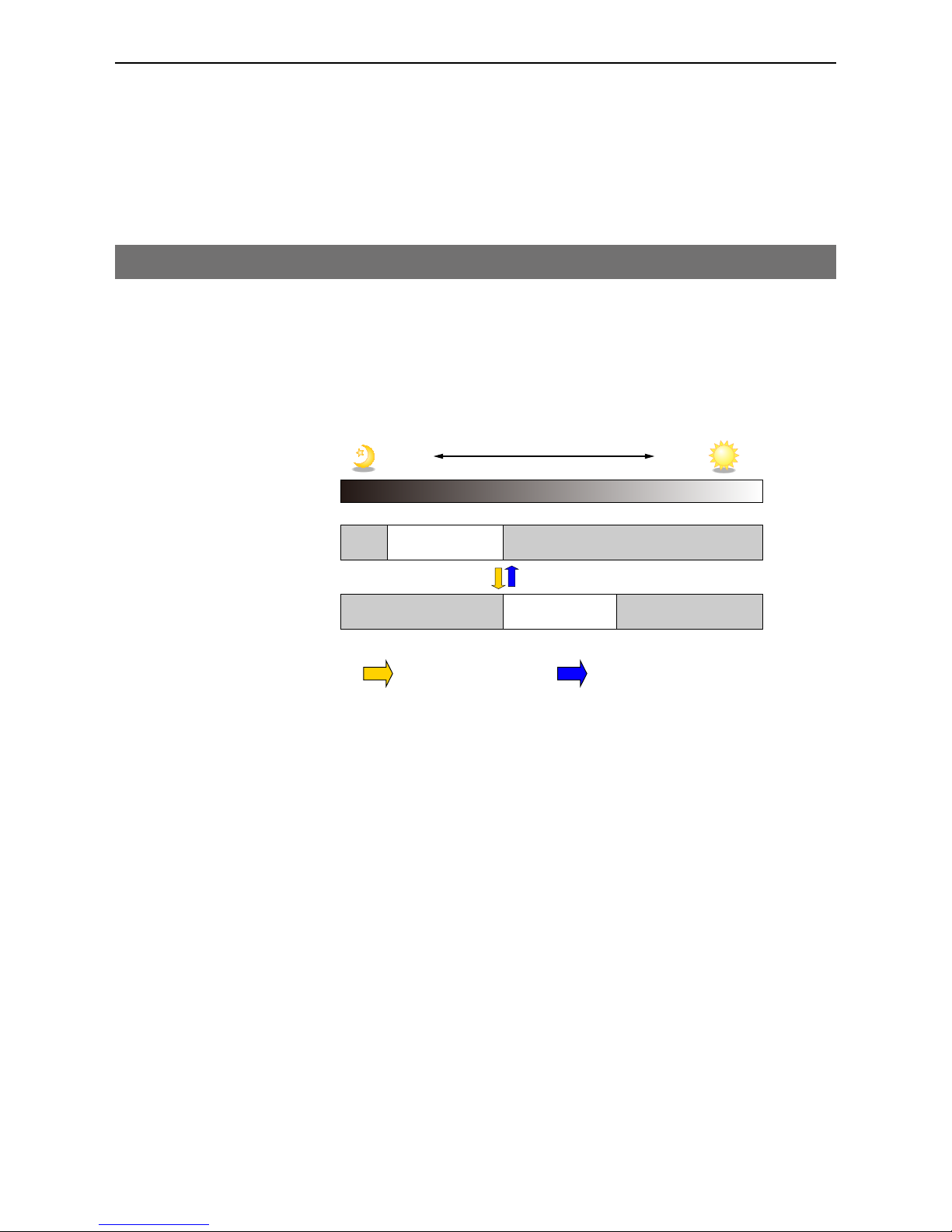
ALC (Automatic Level Control) Function
The ALC (automatic level control) function combines the automatic gain control (AGC/Auto Gain
Control) and automatic exposure control (ASC/Auto Shutter Control) functions, and is capable of
handling various changes in brightness.
The function operates as follows in response to changes in brightness.
Change from bright to dark: ASC AGC
Change from dark to bright: AGC ASC
Change in brightness
Fixed at max. ASC value Fixed at min. ASC value
Fixed at min. gain value
AGC
Max
AGC operation
Max. to min. (user specified)
Operation during change
from dark to bright
Operation during change
from bright to dark
ASC operation
Max. to min. (user specified)
ASC (auto shutter) operation
AGC operation
Dark Bright
■ To use the ALC function
Set [Gain Auto] or [Exposure Auto] or both to [Continuous] mode. Configure the minimum value,
maximum value, etc. for AGC and ASC under [JAI Custom Control ALC].
The target video levels for AGC and ASC are configured in [ALC Reference]. For example, when [ALC
Reference] is set to 100%, video levels will be maintained at 100% for AGC and ASC.
■ Automatic gain level control
Set [Gain] to [Continuous].
Page 41

— 41 —
GO-2400M-USB / GO-2400C-USB
Detailed Settings for Gain Auto (Automatic Gain Level Control)
When [Gain Auto] is set to [Continuous], you can configure the conditions for automatic adjustment in
detail.
Item Description
ALC Reference Specify the target level for automatic gain control. (This
setting is also used for automatic exposure control.)
ALC Area Enable All Select whether to specify all areas as auto gain metering
areas or whether to specify the areas individually.
[0]: Specify areas as auto gain metering areas (16 areas)
individually.
[1]: Specify all areas as auto gain metering areas.
ALC Area Selector Individually select any of 16 areas for automatic gain
metering. (This setting is also used for automatic exposure
control.)
ALC Area Enable Select [True] to enable the metering area selected in [ALC
Area Selector], or select [False] to disable it.
AGC Max. Specify the maximum value for the automatic gain control
range.
AGC Min. Specify the minimum value for the automatic gain control
range.
AGC/ASC Control Speed Specify the reaction speed for automatic gain control. (This
setting is also used for automatic exposure control.)
Auto gain metering areas (16 areas)
Low
Right
Low
Mid-right
Low
Mid-left
Low
Left
Mid-Low
Mid-left
Mid-High
Mid-left
High
Mid-left
Mid-Low
Left
Mid-High
Left
High
Left
High
Mid-right
Mid-High
Mid-right
Mid-Low
Mid-right
High
Right
Mid-High
Right
Mid-Low
Right
Page 42

— 42 —
GO-2400M-USB / GO-2400C-USB
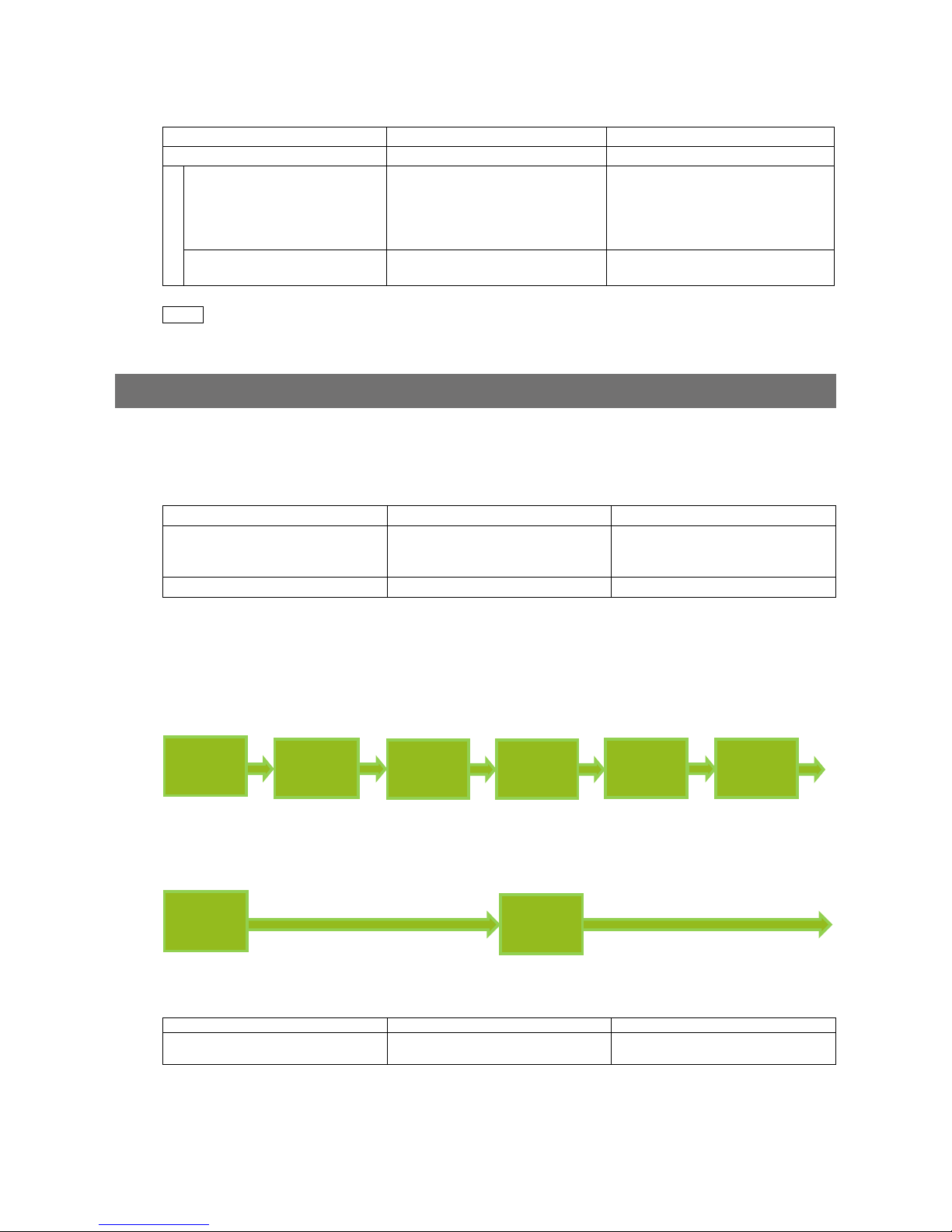
Counter and Timer Control Function (counter support only)
The counter function counts up change points in the camera’s internal signals using the camera’s
internal counter, and reads that information from the host side. This function is useful for verifying error
conditions via the count value using internal camera operations.
Counting is performed at frame trigger, frame start, exposure start, and exposure transfer end, and
by comparing these values, you can determine the internal camera state at which missed triggers will
occur.
■ Counter occurrence diagram
Frame trigger
Frame trigger counter
Set to count 1
Exposure Start
Exposure start counter
Set to count 2
Event occurrence
Event occurrence
Count up
Count up
Count 2
request
Read count
value
Count 1
Request
Read count
value
Counter reset
Counter reset
Count 1 reset
Count 2 reset
MCU
HOST
Note
To reset the counter itself, execute [Counter Reset] or enter “1” in [Counter Reset].
■ Internal camera blocks
Frametrigger
Event
detection
Counter
At event occurrence or count up
Counter
Counter
Counter
Counter reset
Internal MCU of camera
Read requested
counter value
Send
information
to the HOST
Event
detection
Event
detection
Event
detection
Exposure Start
Frame Start
FrameTransfer End
Page 43
— 43 —
GO-2400M-USB / GO-2400C-USB
■ To use the counter function
Configure the settings as follows.
Three counters can be configured (Counter 0 to 2).
Item Setting value / selectable range Description
Counter 0 to 2 Counter 0 to 2 Select the counter.
Counter 0 to 2 Event Source Off,
Frame Trigger,
Frame Start,
Exposure Start,
Exposure Transfer End
Select the counter event signal for
which to read the count value.
Counter 0 to 2 Event Activation Rising Edge (fixed)
or Falling Edge
Specify the timing at which to count.
Note
The three counter event signals are always counted up internally on the camera.
Video Process Bypass Mode
The video process bypass mode is a function that bypasses internal video processing on the camera.
When bypass is enabled, the sensor output and camera output data can be set to the same bit width.
Operation using 12-bit outputs must be performed in bypass mode.
Video process bypass mode On Off
Camera operation All video processes except Gain all
(excluding R/B Gain) and Blemish
Compensation are disabled.
All video processes are enabled.
Camera output 8-/10-/12-bit 8-/10-bit
■ Differences in camera operation
When video process bypass mode is disabled
All video processes are enabled.
Sensor Block
Gain All
Black Level
Block
R/B Black
Level
Pixel Gain
Block
R/B Gain
Shading/
LUT Block
LUT
Blemish
Comp Block
Blemish Comp
BlackSetup
Block
Black Setup
When video process bypass mode is enabled
All video processes except Gain all (excluding R/B Gain) and Blemish Compensation are disabled.
Sensor Block
Gain All
Blemish
Comp Block
Blemish Comp
■ To enable video process bypass mode
Item Setting value / selectable range Description
Video Process Bypass Mode On Enable video process bypass
mode.
Page 44

— 44 —
GO-2400M-USB / GO-2400C-USB
Chunk Data Function
The Chunk Data function adds camera configuration information to the image data that is output from
the camera.
Embedding camera configuration information in the image data allows you to use the serial number of
the camera as a search key and find specific image data from among large volumes of image data. In
addition, when images are shot with a single camera in sequence under multiple setting conditions,
you can search for images by their setting conditions.
The following information can be added to image data as chunk data.
Genicam Name Chunk ID Data type Description
Chunk Image 1000h IRegister Image data (Image data is also handled as a piece of
chunk data.)
Chunk Offset X 2000h IInteger Offset X value
Chunk Offset Y 2001h IInteger Offset Y value
Chunk Width 2002h IInteger Width value
Chunk Height 2003h IInteger Height value
Chunk Pixel Format 2012h IEnumeration Pixel Format value
Chunk Timestamp 2014h IInteger Timestamp value
Chunk Line Status All 2013h IInteger [0]: Line1 - TTL Out 1
[1]: Line2 - Opt Out 1
[2]: Line3 - Opt Out 2
[3]: Line4 - TTL In 1
[4]: Line5 - Opt In 1
[5]: Line6 - Opt In 2
[6]: Line7 - CC1/CXP In
[7]: Line8 - TTL Out 2 (Option)
[8]: Line9 - TTL Out 3 (Option)
[9]: Line10 - TTL In 2 (Option)
[10]: Line11 - LVDS In (Option)
[11]: TimeStampReset
[12]: Nand0_In_1
[13]: Nand0_In_2
[14]: Nand1_In_1
[15]: Nand1_In_2
Chunk Exposure Time
(us)
2004h IFloat ExposureTime value for when Exposure Mode is set
to Timed
Chunk Gain All 2005h IFloat Gain All value
Chunk Gain Red 2006h IFloat Gain Red value*
Chunk Gain Blue 2007h IFloat Gain Blue value*
Chunk Black Level All 2008h IFloat Black Level Alll value
Chunk Sequencer Set
Active
200Ch IInteger Value indicating the Sequencer status
Chunk Frametrigger
Counter
200Eh IInteger Counter value for FrameTtrigger
Chunk Exposure Start
Counter
200Fh IInteger Counter value for ExposureStart
Chunk Frame Start
Counter
2010h IInteger Counter value for FrameStart
Chunk Frame Transfer End
Counter
2011h IInteger Counter value for FrameTransferEnd
Chunk Line Status All On
FVAL Start
2016h IInteger The line status is added when FVAL is established.
The content of the data is identical to
[ChunkLineStatusAll].
Chunk Device
Temperature
2019h IFloat Device Temperature value
Chunk Device Serial
Number
2017h IString Device Serial Number value
Chunk Device User ID 2018h IString Decice User ID value
*
GO-2400C-USB only
Page 45

— 45 —
GO-2400M-USB / GO-2400C-USB
■ Configuring Chunk Data
1
Set [Chunk Mode Active] to [True].
2
Select the items of information you want added to image data with [Chunk Selector], and
set [Chunk Enable] from [False] to [True].
Note
When [Chunk Mode Active] is set to [True], [Chunk Image] is automatically set to [True].
Caution
The Chunk Data function settings cannot be changed during image output. To change the settings,
stop Acquisition.
Page 46

— 46 —
GO-2400M-USB / GO-2400C-USB
Settings List
Feature Properties
: Settings that can only be configured when image acquisition on the camera is stopped.
Item Setting range Default value Description
a) Device Control
Display/configure information related to
the device.
Device Vendor Name — — Display the manufacturer name.
Device Model Name — — Display the model name.
Device Manufacturer Info — See the
possibilities
Display the device information.
Device Version — — Display the hardware version.
Device Firmware Version — — Display the firmware version.
Device Serial Number — — Display the device ID.
Device User ID Any — Set the user ID for the camera.
Device Temperature Selector Mainboard Mainboard Select the area of the camera's interior for
which to display the temperature sensor's
reading.
Device Temperature (C) — — Display the internal temperature (˚C) of
the camera.
Device Reset — — Reset the device.
b) Image Format Control
Configure image format settings.
Sensor Width 1936 1936 Display the maximum image width.
Sensor Height 1216 1216 Display the maximum image height.
Width Max — 1936 Display the maximum image width.
Height Max — 1216 Display the maximum image height.
Width Binning Off: 16 to 1936
Binning 2 On: 16 to 968
❖ The minimum value for
Monochrome varies
depending on the
[Binning] setting.
1936 Set the image width.
Height GO-2400M-USB:
Binning Off: 1 to 1216
Binning 2 On: 1 to 608
GO-2400C-USB: 2 to 1216
❖ The minimum value for
Monochrome varies
depending on the
[Binning] setting.
1216 Set the image height.
Offset X 0 to (1936 to Width) 0 Set the horizontal position.
Offset Y 0 to (1216 to Height)1 0 Set the vertical position.
Binning Horizontal Mode
(GO-2400M-USB only)
Sum, Average Sum Set the addition process to be used
during horizontal binning.
Binning Horizontal
(GO-2400M-USB only)
1, 2 1 Set the number of pixels in the horizontal
direction for which to perform binning.
Binning Vertical
(GO-2400M-USB only)
1, 2 1 Set the number of pixels in the vertical
direction for which to perform binning.
Binning Vertical Mode
(GO-2400M-USB only)
Sum, Average Sum Display the addition process to be used
during vertical binning.
Page 47

— 47 —
GO-2400M-USB / GO-2400C-USB
Item Setting range Default value Description
Pixel Format GO-2400M-USB:
8 Bit Monochrome,
10 Bit Monochrome,
10 Bit Monochrome
Packed,
12 Bit Monochrome,
12 Bit Monochrome
Packed
GO-2400C-USB:
8 Bit Bayer RG,
10 Bit Bayer RG
(Unpacked),
10 Bit Bayer RG Packed,
12 Bit Bayer RG
(Unpacked),
12 Bit Bayer RG Packed
GO-2400M-USB:
8 Bit
Monochrome
GO-2400C-USB:
8 Bit Bayer RG
Set the pixel format.
Test Pattern GO-2400M-USB:
Off,
GreyHorizontal
Ramp,
GreyVertical
Ramp,
GreyHorizontalRamp
Moving
GO-2400C-USB:
Off,
GreyHorizontalRamp,
GreyVerticalRamp,
GreyHorizontalRamp
Moving,
HorizontalColorBar,
VerticalColorBar,
MovingColorBar
Off Select the test image.
c) Acquisition Control
Configure image acquisition settings.
Acquisition Mode Single Frame, Multi Frame,
Continuous
Continuous Select the image acquisition mode.
Acquisition Start — — Start image acquisition.
Acquisition Stop — — Stop image acquisition.
Acquisition Frame Count 1 to 255 1 In [Multi Frame] mode, set the number of
frames to acquire.
Acquisition Frame Rate (Hz)*
* Max. frequency/min. frame
period depends on ROI, pixel
format, and binning mode
selected.
0.125 to 159.286 159.286
Set the frame rate as a frequency. (unit: Hz)
Trigger Selector Acquisition Start,
Acquisition End, Frame Start,
Acquisition Transfer Start
Frame Start Select the trigger operation.
Trigger Mode Off, On Off Select the trigger mode.
Trigger Software — — Execute a software trigger.
Trigger Source Low, High, Software,
Pulse Generator 0,
User Output 0,
User Output 1,
Line 5 - Optical In 1,
NAND0 Out, NAND1 Out
Line 5 - Optical
In 1
Select the trigger signal source.
Trigger Activation Rising Edge,
Falling Edge
Rising Edge
(rising edge of
input signal)
Select the polarity of the trigger signal
(i.e., location of signal at which trigger is
applied).
Trigger OverLap Off, Read Out
(Frame Start only)
Off Select the trigger overlap operation.
Exposure Mode Off, Timed, Trigger Width Timed (control
via exposure
time)
Select the exposure mode.
Exposure Time 6 to 6210 (µs) 6210 (µs) Set the exposure time.
Exposure Auto Off, Continuous Off Set whether to enable auto exposure.
d) Analog Control
Configure analog control settings.
Page 48

— 48 —
GO-2400M-USB / GO-2400C-USB
Item Setting range Default value Description
Gain Selector GO-2400M-USB: Analog All
GO-2400C-USB: Analog All,
Digital Red,
Digital Blue
Analog All
(master gain)
Select the gain to configure.
Gain Analog All: 1 to 16
Digital Red & Blue:
0.447 to 5.624 (color
only)
Master gain: 1
R, B: 1
Set the gain value.
Black Level Selector GO-2400M-USB: Digital All
GO-2400C-USB: Digital All,
Digital Red, Digital Blue
Digital All
(master black)
Select the black level to configure.
Black Level Digital All: –133 to 255
Digital Red & Blue:
–133 to 255 (color only)
0 Set the black level value.
Gain Auto Off, Continuous Off Enable/disable gain auto adjustment.
Gamma 0.45, 0.60, 1.0 0.45 Set the gamma value.
JAI LUT Mode Off, Gamma, LUT Off Select the JAI LUT mode.
e) LUT Control
Configure LUT settings.
LUT Selector
(GO-2400C-USB only)
R, G, B R Select the LUT channel to control.
LUT Index GO-2400M-USB: 0 to 256
GO-2400C-USB: 0 to 256
0 Set the LUT index table number.
LUT Value 0 to 4095 0 Set the LUT value.
f) Digital IO Control
Configure settings for digital input/output.
Line Selector Line2 - Opt Out 1,
Line3 - Opt Out 2,
Line5 - Opt In 1,
Time Stamp Reset,
NAND Gate 0 In 1,
NAND Gate 0 In 2,
NAND Gate 1 In 1,
NAND Gate 1 In 2
Line2 - Opt Out 1 Select the input/output to configure.
Line Mode — Output Display the input/output status (whether it
is input or output).
Line Inverter True, False False Enable/disable polarity inversion for the
selected input signal or output signal.
Line Status — False Display the status of the input signal or
output signal (True: High, False: Low).
LineSource Low, High,
Acquisition Trigger Wait,
Frame Trigger Wait,
Frame Active,
Exposure Active,
FVAL,
User Output 0,
User Output 1,
Line 5 - Opt In 1,
Pulse Generator 0,
Nand 0 Out, Nand 1 Out
Low Select the line source signal for the item
selected in [Line Selector].
Line Format — Opto Coupled Display the current I/F type.
Line Status All — 0x00 Display the status of the input signal and
output signal.
User Output Selector User Output 0,
User Output 1
User Output 0 Set the user output signal.
User Output Value True, False False
g) Counter And Timer Control
Configure counter settings. (This camera
only supports counter functions.)
Counter 0 to 2 Counter 0 to 2 — Display the counter.
Page 49

— 49 —
GO-2400M-USB / GO-2400C-USB
Item Setting range Default value Description
Counter 0 to 2 Event
Source
Off, Frame Trigger,
Frame Start,
Exposure Start,
Exposure Transfer End
Off Select the counter event signal for which
to read the count value.
Counter 0 to 2 Event
Activation
Rising Edge (fixed) Rising Edge Specify the timing at which to count.
Counter 0 to 2 Reset — — Reset the counter.
Counter 0 to 2 Refresh — — Update the count value.
Counter 0 to 2 Value — 0 to 2 Display the count value.
Counter 0 to 2 Status — Counter Active Display the counter status.
h) User Set Control
Configure user settings.
User Set Selector Default,
User Set1 to User Set3
Default (factory
default values)
Select the user settings.
User Set Load — — Load user settings.
User Set Save — — Save the current setting values as user
settings.
i) Sequencer Control
Configure sequencer settings.
Sequencer Mode On, Off Off Enable/disable [Sequencer Mode].
Sequencer Mode Select Trigger Sequencer,
Command Sequencer
Trigger
Sequencer
Select the sequencer mode.
Sequencer Configuration Mode On, Off On Select [On] to change the settings within
the index.
Sequencer Set Selector 1 to 128 1 Select the [Trigger Sequencer] mode and
[Command Sequencer] mode index.
Sequencer Frame Number 1 to 255 1 Set the number of frames to display for
the selected Sequencer Index. (Enabled
only for Trigger Sequencer.)
Sequencer Set Next 0 (Off), 1 to 128 1 Set the next index to be displayed for the
selected Sequencer Index. (Enabled only
for Trigger Sequencer.)
Sequencer Width GO-2400M-USB:
16 to 1216
GO-2400C-USB:
16 to 1936
1936 Set the width of the selected Sequencer
Index.
Sequencer Height 2 to 1216 1216 Set the height of the selected Sequencer
Index.
Sequencer Offset X 0 to (1936 - Width) 0 Set the horizontal offset value for the
selected Sequencer Index.
Sequencer Offset Y 0 to (1218 - Height) 0 Set the vertical offset value for the
selected Sequencer Index.
Sequencer Gain 100 to 1600 100 Set the gain for the selected Sequencer
Index.
Sequencer Exposure Time
(US)
6 to 8000000 6210 Set the exposure time for the selected
Sequencer Index.
Sequencer Black Level -133 to 255 0 Set the black level for the selected
Sequencer Index.
Sequencer LUT Enable True, False False Enable/disable the LUT setting for the
selected Sequencer Index.
Sequencer H Binning
(GO-2400M-USB only)
1 to 2 1 Set the horizontal binning for the selected
Sequencer Index.
Sequencer V Binning
(GO-2400M-USB only)
1 to 2 1 Set the vertical binning for the selected
Sequencer Index.
Sequencer Repetition 1 to 255 1 Set the repeat count for the sequencer.
Sequencer LUT Mode Gamma, LUT Gamma Set the sequencer LUT mode.
Sequencer Set Active — — Displays the active LUT number.
Sequencer Command Index 1 to 128 1 Set this to change the Sequencer Index.
(Enabled only for Command Sequencer.)
Sequencer Set Start 1 to 128 1 Set the index number that is used when
executing [Sequencer Reset] in [Trigger
Sequencer] mode.
Sequencer Reset — — Reset the current index number to the
number configured in [Sequencer Set
Start].
j) Chunk Data Control
Configure Chunk Data function settings.
Chunk Mode Active True, False False Enable/disable the Chunk Data function.
Page 50

— 50 —
GO-2400M-USB / GO-2400C-USB
Item Setting range Default value Description
Chunk Selector Chunk Image,
Chunk Offset X,
Chunk Offset Y,
Chunk Width,
Chunk Height,
Chunk Pixel Format,
Chunk Timestamp,
Chunk Line Status All,
Chunk Exposure rtime (us),
Chunk Gain All,
Chunk Gain Red,*
Chunk Gain Blue,*
Chunk Black Level All,
Chunk Sequencer Set
Active,
Chunk Frame Trigger
Counter,
Chunk Exposure Start
Counter,
Chunk Frame Start Counter,
Chunk Frame Transfer End
Counter,
Chunk Line Status All On
FVAL Start,
Chunk Device Temperature,
Chunk Device Serial
Number,
Chunk Device User ID
Image Select the information you want added to
the image data.
* GO-2400C-USB only
Chunk Enable True, False — Select whether to add the information to
the image data.
Default value: [Chunk Image] only "True"
k) Transport Layer Control
Display information on transport layer
control.
Payload Size (B) — 2354176 Display the payload size.
Device Tap Geometry Geometry_1X1_1Y Geometry_1X1_ 1YSet the transmission method for each time
images are transmitted from the device
(TAP structure).
l) JAI Custom Control Pulse
Generators
Configure pulse generator settings.
Clock Pre-scaler 1 to 4096 165 Set the division value for the prescaler
(12-bit) using the pixel clock as the base
clock.
Pulse Generator Clock (MHz) 0.018127 to 74.25 0.45 Set the clock used for the pulse
generator.
This value is calculated based on the
Clock Pre-Scaler value.
Pulse Generator Selector Pulse Generator 0 Pulse Generator 0Select the pulse generator.
Page 51

— 51 —
GO-2400M-USB / GO-2400C-USB
Item Setting range Default value Description
Pulse Generator Length 1 to 1048575 30000 Set the maximum count up value using
clock value.
Pulse Generator Length
(ms)
0.002222 to 2330.166666 66.6667 Set the maximum count up value using
ms.
This value is calculated based on the
Pulse Generator Length value.
The setting range varies depending on
the Clock Pre-Scaler value.
Pulse Generator Frequency
(Hz)
0.429154 to 450000 15 Set the maximum count up value using
frequency.
This value is calculated based on the
Pulse Generator Length value.
Pulse Generator Start Point 0 to 1048574 0 Set the start point for the High interval
using clock value.
When the counter reaches this value, the
output becomes 1.
Pulse Generator Start Point
(ms)
0 to 2330.164444 0 Set the start point for the High interval
using ms.
When the counter reaches this value, the
output becomes 1.
The setting range varies depending on
the Clock Pre-Scaler value.
Pulse Generator End Point 1 to 1048575 15000 Set the start point for the Low interval
using clock value.
When the counter reaches this value, the
output becomes 0.
Pulse Generator End Point
(ms)
0.000013468 to 14.1222 33.3333 Set the start point for the Low interval
using ms.
When the counter reaches this value, the
output becomes 0.
The setting range varies depending on
the Clock Pre-Scaler value.
Pulse Generator PulseWidth (ms)
-
33.3333 Display High interval width for the pulse in
ms.
This is a calculation of the time between
the Start Point and End Point.
The setting range varies depending on
the Clock Pre-Scaler value.
Pulse Generator Repeat
Count
0 to 255 0 Set the repeat count for the counter.
When this is set to 0, the counter will be
free-running with limitless repeating.
Pulse Generator Clear
Activation
Off,
High Level,
Low Level,
Rising Edge,
Falling Edge
0: Off Set the clear signal condition for the
count clear input of the pulse generator.
Pulse Generator Clear
Source
Low, High,
Acquisition Trigger Wait,
Frame Trigger Wait,
Frame Active,
Exposure Active,
FVAL,
LVAL,
User Output 0,
User Output 1,
Action 1,
Action 2,
Line 5 - Opt In 1,
Nand0 Out,
Nand1 Out
0: Low Select the count clear input signal source.
Line4 TTL In is available on Standard
Model.
Pulse Generator Clear
Inverter
True, False False Select whether to invert the polarity of the
count clear input signal.
Pulse Generator Clear
Sync Mode
Async Mode, Sync Mode Async Mode Select the sync mode for the count clear
input signal.
m) JAI Custom Control ALC
Configure JAI ALC settings. These
settings are also used for AGC (auto gain
control).
ALC Reference 10 to 95 50 Set the target level for ALC. (unit: %)
ALC Area Selector Low Right to High Left Low Right Select an ALC metering area.
ALC Area Enable True, False False Enable/disable the metering area where
selected metering area.
Page 52

— 52 —
GO-2400M-USB / GO-2400C-USB
Item Setting range Default value Description
ALC Area Enable All True, False
True
Set whether to enable ALC for all areas.
ASC Min. 100 to 6209 100 Set the minimum value for the ASC range.
ASC Max. 101 to 6210 6210 Set the maximum value for the ASC
range.
AGC Min. 100 to 1599 100 Set the minimum value for the AGC
range.
AGC Max. 101 to 1600 1600 Set the maximum value for the AGC
range.
AGC/ASC Control Speed 1 to 8 4 Set the reaction speed for AGC/ASC.
These settings are also used for auto
exposure control.
ALC Status — Idle Display the status of the ALC.
n) JAI Custom Control Blemish
Configure settings for JAI white blemish
correction.
Blemish Enable True, False True Set whether to enable white blemish
correction.
Blemish Detect — — Detect white blemishes.
Blemish Detect Threshold 0 to 100 10 Set the white blemish detection threshold.
Blemish Detect Position Index 0 to 511 0 Select the index table for the white
blemish detection position.
Blemish Detect Position X –1 to 1935 –1 Set the horizontal position.
Blemish Detect Position Y –1 to 1215 –1 Set the vertical position.
Blemish Compensation
Number
— 0 Display the number of correction
blemishes.
o) JAI Custom Control Shading
Configure shading correction settings.
Shading Correction Mode GO-2400M-USB:
Flat Shading (fixed)
GO-2400C-USB:
Flat Shading, Color
Shading
Flat Shading Select the shading correction mode.
Shading Mode Off, User 1, User 2, User 3 Off Select whether to use shading correction.
When using the function, select the user
area to which to save the shading
correction value.
Perform Shading Calibration — — Execute shading correction. After
execution, the shading correction value is
automatically saved to the selected user
area.
Shading Detect Result — — Display the shading detection results.
p) JAI Custom Control Sensor
MultiROI
Configure settings for JAI sensor multi
ROI.
Sensor Multi Roi Enable True, False False Enable/disable sensor multi ROI.
Sensor Multi Roi Index Index 1 to 4 Index 1 Select the sensor multi ROI index table.
Sensor Multi Roi Width 16 to 1936/16 steps 256 Set the width. When binning is enabled
on the GO-2400M-USB, the maximum
value will change.
Sensor Multi Roi Height 2 to 1216/2 steps 160 Set the height. When binning is enabled
on the GO-2400M-USB, the maximum
value will change.
Sensor Multi Roi Offset X 0 to 1680/16 steps
❖ maximum value
= 1936 - width value
0 Set the horizontal position. When binning
is enabled on the GO-2400M-USB, the
maximum value will change.
Sensor Multi Roi Offset Y 0 to 1056/2 step
❖ maximum value
= 1216 - height value
0 Set the vertical position. When binning is
enabled on the GO-2400M-USB, the
maximum value will change.
Horizontal Enable True, False False Enable/disable horizontal offset.
Vertical Enable True, False False Enable/disable vertical offset.
Page 53

— 53 —
GO-2400M-USB / GO-2400C-USB
Item Setting range Default value Description
q) JAI Custom control Misc.
Configure settings for other JAI functions.
Video Process Bypass
Mode
On, Off Off Enable / disable video process bypass
mode.
Trigger Option Off Off —
OptIn Filter Selector 10 us, 100 us, 500 us, 1 ms,
5 ms, 10 ms
10 us Select the surge protection filter.
Video Send Mode Normal Mode,
Trigger Sequence Mode,
Command Sequence Mode
Normal Display the video send mode status.
Sensor LVDS Ch Num 8 8 Display the number of sensor output
LVDS channels.
Sensor Digitization Bits 10,12 12 Display the resolution per pixel of sensor
output.
Page 54

— 54 —
GO-2400M-USB / GO-2400C-USB
Miscellaneous
Troubleshooting
Check the following before requesting help. If the problem persists, contact your local JAI distributor.
■ Power supply and connections
Problem Cause and solution
The power / trigger LED remains lit amber and
does not turn green, even after power is
supplied to the camera.
Camera initialization may not be complete due to lack of a
network connection. Check the USB cable conection.
■ Image display
Problem Cause and solution
Gradation in dark areas is not noticeable. Use the gamma function to correct the display.
As the light-emitting properties of the monitor are not linear,
the entire image may be darker or the gradation in the dark
areas may be less noticeable when camera outputs are
displayed without processing. Using the gamma function
performs correction to produce a display that is close to
linear.
For details, see “Gamma Function” (page 31).
■ Settings and operations
Problem Cause and solution
Settings cannot be saved to user memory. You cannot save to user memory while images are being
acquired by the camera. Stop image acquisition before
performing the save operation.
I want to restore the factory default settings. Load [Default] under [User Set Selector] in the [Feature
Properties] tab to restore the factory default settings.
Page 55

— 55 —
GO-2400M-USB / GO-2400C-USB
Specifications
Item GO-2400M-USB GO-2400C-USB
Scanning system Progressive scan, 1 tap
Synchronization Internal
Interface USB 3.0 Vision (Specification V1.0 RC4.02) compatible
Image sensor 1/1.2-inch monochrome CMOS 1/1.2-inch Bayer color CMOS
Image size (effective image) 11.3 (H) × 7.13 (V), 13.4 mm diagonal
Pixel size 5.86 (H) × 5.86 (V) µm
Effective image pixel output 1936 (H) × 1216 (V) 1936 (H) × 1216 (V)
Acquisition Frame
Rate (max)
❖ The minimum
value is 0.125
fps for all.
8-bit H1, V1 159 fps 159 fps
Binning H1, V2 164 fps —
H2, V1 164 fps —
H2, V2 164 fps —
10-bit
packed /
12-bit
packed
H1, V1 127 fps 127 fps
Binning H1, V2 127 fps —
H2, V1 127 fps —
H2, V2 127 fps —
10-bit /
12-bit
H1, V1 79 fps 79 fps
Binning H1, V2 127 fps —
H2, V1 127 fps —
H2, V2 127 fps —
EMVA 1288 parameters
Absolute sensitivity
Maximum SN ratio
At 12-bit output
9.44p (λ = 525 nm)
45.16 dB
At 12-bit output
10.86p (λ = 525 nm)
45.23 dB
SN ratio (traditional method) 60 dB or more (typical)
(0 dB gain, Black)
60 dB or more (typical)
Dark compression ON: 50 dB
(typical)
(0 dB gain, Green Black)
Digital image
output format
Full pixel 1936 (H) × 1216 (V)
Bayer 1936 (H) × 1216 (V)
ROI Width 16 to 1936, 16 pixels/step 16 to 1936, 16 pixels/step
Offset X 0 to 1920, 16 pixels/step 0 to 1920, 16 pixels/step
Height 1 to 1216, 1 line/step 2 to 1216, 2 lines/step
Offset Y 0 to 1215, 1 line/step 0 to 1214, 2 lines/step
Binning H 1 1936 (H) 1936 (H)
2 968 (H) —
V 1 1216 (V) 1216 (V)
2 968 (V) —
Pixel Format Mono8, Mono10, Mono10
Packed, Mono12,
Mono12 Packed
BayerGR8, BayerGR10,
BayerGR10 Packed, BayerGR12,
BayerGR12 Packed
Trigger selector Exposure Frame Start
Exposure modes Off, Timed (EPS), Trigger Width (PWC)
Trigger overlap Off
Trigger input signals Line 5 (Opt In), Software, PG0, NAND Out 0/1
Exposure modes Timed 6 µs (8-bit), 7 µs (10-bit) (min) to 8 s (max), variable unit: 1 µs
❖ Performance verified for up to 1 second.
Trigger Width 6 µs (8-bit), 7 µs (10-bit) (min) to 8 s (max)
❖ Performance verified for up to 1 second.
Auto exposure (Exposure Auto) Off, Continuous
Auto exposure response speed
(AGC/ASC Control Speed)
1 to 8
Video send modes Normal Mode, Trigger Sequencer Mode, Command
Sequencer Mode, Multi Mode
Digital I/O Line Selector (6P): GPIO IN / GPIO OUT
Black level
adjustment
Default level 33LSB (during 10-bit output)
Video level adjustment range R/B: 20 to 60 (during 10-bit output)
Adjustment range –33LSB to +64LSB against reference level (during 10-bit output)
Resolution adjustment 1 STEP = 0.25LSB
Page 56

— 56 —
GO-2400M-USB / GO-2400C-USB
Item GO-2400M-USB GO-2400C-USB
Gain adjustment Manual adjustment range 0 dB to +24 dB 0 dB to +24 dB
Auto gain Off, Continuous Off, Continuous
WB gain — R / B: –7 dB to +15 dB, 1 step =
0.1 dB
WB Preset — 4600K, 5600K, 6500K
WB area — 16 (4 × 4) Area
WB range — 3000 K to 9000 K
White balance — Off, Continuous, Once
Blemish correction Detection Detect white blemishes using threshold values
(black blemish correction performed only at factory)
Correction Interpolation using adjacent pixels (continuous blemishes not
corrected)
Correctable pixels 256 pixels
ALC Can be adjusted automatically together with AGC and auto exposure
Gamma 0.45, 0.6 an, 1.0 (OFF) (3 steps available)
LUT
OFF: γ = 1.0, ON = 257 points can be set
Power supply 6-pin
connector
Input range DC +12 V to +24 V ±10% (via input terminal)
Power consumption 4.08 W (at 12 V input, full pixel) (Typical)
USB bus
power
Input range DC 36 V to 57 V
Power consumption 4.1 W (at 5 V input, full pixel) (Typical)
Lens mount C-mount
Lens mount protrusion length of 9 mm or less is supported
Flange back 17.526, tolerance: 0 mm to –0.05 m
Optical filter Protective glass: Not provided IR cut filter (half value of 670 nm)
Verified performance temperature / humidity –5°C to +45°C / 20% to 80% (non-condensing)
Storage temperature / humidity –25°C to +60°C / 20% to 80% (non-condensing)
Regulations CE (EN61000-6-2 and EN61000-6-3), FCC part 15 class B, RoHS,
WEEE
Dimensions (housing) 29 × 29 × 41.5 mm (WHD) (excluding mount protrutions)
Weight 46 g
Approximately 5 minutes of warm-up are required to achieve these specifications.
Package contents
Camera body (1)
Sensor protection cap (1)
Dear Customer (sheet) (1)
Optional accessories (not supplied)
MP-43 tripod mount
AC adapter
Design and specifications are subject to change without notice.
Page 57

— 57 —
GO-2400M-USB / GO-2400C-USB
Frame Rate Reference
(Theoretical value: decimal values are dropped)
Pixel count
Resolution
(screen size)
ROI/Binning Pixel size(μm) Image size
Frame rate
8 / 10 / 12 bit
2.35 MP 1936 × 1216 Full pixel 5.86 × 5.86 1/1.2" (13.40 mm) 159 fps (@8 bit)
2 MP 1920 × 1080 ROI 5.86 × 5.86 1/1.2" (12.91 mm) 180 fps (@8 bit)
1.4 MP 1392 × 1050 ROI 5.86 × 5.86 1/1.6" (10.26 mm) 189 fps (@8 bit)
1.3 MP 1280 × 1024 ROI 5.86 × 5.86 1/1.7" (9.61 mm) 193 fps (@8 bit)
0.5 MP 800 × 600 ROI 5.86 × 5.86 1/2.7" (5.86 mm) 322 fps (@8 bit)
0.3 MP 640 × 480 ROI 5.86 × 5.86 1/3.4" (4.69 mm) 396 fps (@8 bit)
Spectral Response
GO-2400M-USB
0
0.1
0.2
0.3
0.4
0.5
0.6
0.7
0.8
0.9
1
400 500 600 700 800 900 1000
Sensitivity
wave length (nm)
GO-2400M/2401M Sensitivity
B&W
Page 58
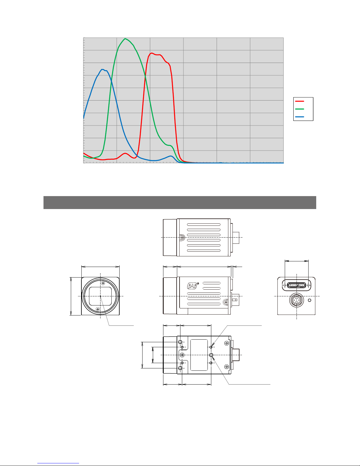
— 58 —
GO-2400M-USB / GO-2400C-USB
GO-2400C-USB
0
0.1
0.2
0.3
0.4
0.5
0.6
0.7
0.8
0.9
1
400 500 600 700 800 900 1000
Sensitivity
wave length (nm)
GO-2400C/2401C Sensitivity
Rch
Gch
Bch
Dimensions
12
20
10 41.5
12.5
23.7
14 22
29
29
C Mount
4-M2 Depth3
3-M3 Depth3
1.5
18
Dimensional tolerance: ±0.3
mm
Unit: mm
Page 59

— 59 —
GO-2400M-USB / GO-2400C-USB
User’s Record
Camera type: GO-2400M-USB / GO-2400C-USB
Revision: ……………..
Serial No. ……………..
Firmware version. ……………..
For camera revision history, please contact your local JAI distributor.
Trademarks
• Microsoft and Windows are trademarks or registered trademarks of Microsoft Corporation in the United States and other
countries.
• Intel and Intel Core are trademarks of Intel Corporation in the United States and other countries.
Other system and product names described in this document are trademarks or registered trademarks of their respective
owners. The ™ and ® symbols are not used in this document.
Page 60

— 60 —
GO-2400M-USB / GO-2400C-USB
6-pin round
9
A
AC adapter
13
Acquisition Control
24
acquisition modes
24
Adjusting the Black Level
20
Adjusting the Gain
19
Adjusting the White Balance
20
ALC
40
Automatic Level Control Function
40
B
black level
20
C
Camera locking screw holes
10
C-mount
12
Configuring Exposure
16
Connecting Devices
12
Counter and Timer Control Function
42
D
DC IN
9
DC IN / trigger IN connector
9
Digital Input/Output Settings
23
Dimensions
58
E
exposure
16
Exposure Mode
26
External Trigger Settings
16
F
factory default settings
54
Feature Properties
46
Frame Rate
24
Frame Rate Reference
57
G
Gain Auto
41
Gain Level
41
Gamma Function
31
GPIO
23
I
Initial Settings for the Camera
14
Installing the Software
11
J
JAI Camera Control Tool
11
JAI SDK
11
L
LED
8
Lens
12
Lens mount
8
Lookup Table
30
LUT
30
O
Optional accessories (not supplied)
56
Output format
15
P
Parts Identification
8
Power/trigger LED
8
R
Regional Scanning Function
34
RJ-45 connector
8
ROI
34
S
Saving the Settings
20
Settings List 44,
46
Shading Correction
32
software
11
Specifications
55
Spectral Response
57
T
Trigger Control
26
trigger IN
9
Trigger Selector
26
Troubleshooting
54
U
USB cable
13
V
Verifying the Camera’s Network
Connection Status
14
Video Process Bypass Mode
43
W
white balance
20
Index
Page 61

Revision history
Revision Date Changes
1.0 Mar 2017 First draft
 Loading...