

Page 1

ERC Actuator with
Integrated Controller
Operation Manual Forth Edition
Page 2

CAUTION
2. Basic Parameter Settings
When the power is input for the first time, at least the two parameters specified below must be set in
accordance with the intended application.
If these parameters are not set properly, the ERC will not function correctly. So, pay due attention to
ensure the parameters are set properly.
For details on the setting method, refer to the “parameter settings” of the PC or teaching pendant.
[1] PIO pattern selection
This controller provides three PIO (parallel I/O) patterns to support various applications.
To select a desired PIO pattern, set a number between “0” and “2” in parameter No. 25 (PIO pattern
selection).
The factory setting is “0.”
Setting of parameter
No. 25
0
1
2
[2] Enabling/Disabling the Pause Signal (*STP)
The pause signal uses the contact B logic to provide a failsafe function.
Therefore, this signal must remain ON in normal conditions of use.
Since there are applications where this signal is not used, a parameter is provided to disable the
pause signal so it doesn’t have to be turned ON.
To select a desired setting, set “0” or “1” in user parameter No. 15 (Pause input disable selection).
Enable (use) the signal 0
Disable (do not use) the signal 1
The factory setting for this parameter is “0: [Enable].”
8 points
The basic pattern providing eight positioning points.
3 points (air cylinder)
Use of the ERC as an air cylinder is assumed in this pattern.
The number of positioning points is limited to three, but a direct
command input and a position complete output are provided for each
target position in line with the conventional practice of air cylinder
control.
This lets the user control the ERC just like an air cylinder.
16 points
The number of positioning points is increased to 16.
However, the home return input is not provided.
Setting
Feature of the PIO pattern
Page 3

CAUTION
3. Recommendation for Backing up Latest Data
The controller part of this actuator uses nonvolatile memory to store the position table and
parameters. Normally the memory will retain the stored data even after the power is disconnected.
However, the data may be lost if the nonvolatile memory becomes faulty.
(We strongly recommend that the latest position table and parameter data be backed up so that the
data can be restored quickly in the event of power failure, or when the controller must be replaced for
a given reason.)
The data can be backed up using the following methods:
[1] Save to a CD or FD from the PC software.
[2] Hand write the position table and parameter table on paper.
4. Compatibility of Teaching Pendant
The existing teaching pendants of <RCA-T> and <RCA-E> types can be used with the ERC
controller, but your RCA-T/RCA-E teaching pendant will require some modification.
If you are using a teaching pendant of either type, please send it to IAI. We will perform the
necessary modification and return it to you as soon as possible.
Teaching pendants that have already been modified have a specific code at the end of their serial
number. Please check the serial number of your teaching pendant to see if it requires modification.
Teaching pendant model Code at the end of serial number
RCA-T
RCA-E
RCA-P
RCB-J
• • • • • • • F3
• • • • • • • H3
• • • • • • • H3
• • • • • • • B2
Page 4
CAUTION
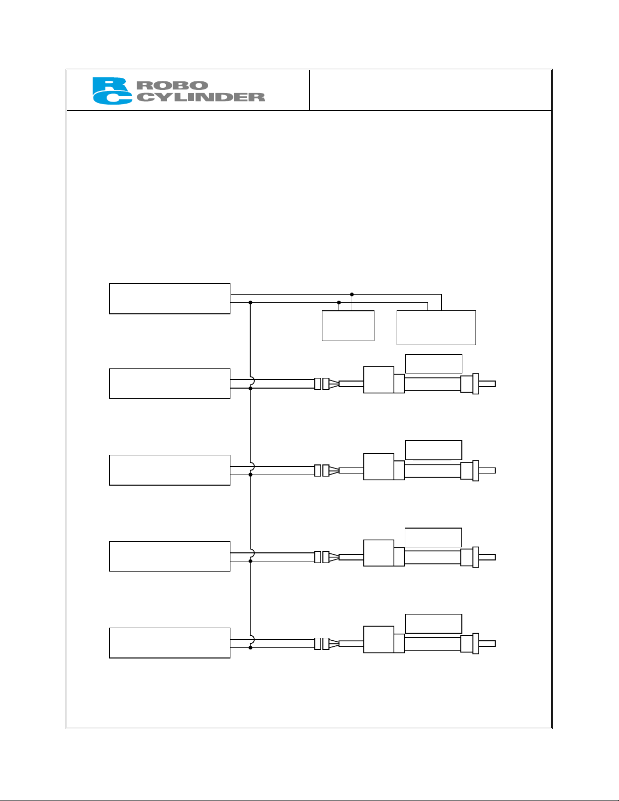
1. When Using Multiple 24-V Power Supplies
If multiple 24-V power supplies are used, be sure to adjust 0 V to the same level on
all units. If 0 V varies among the power supplies, the controller board, SIO converter
or other hardware may be damaged.
[Connection example]
24-V power supply
[1]
24-V power supply
[2]
24-V power supply
[3]
24-V power supply
[4]
24-V power supply
[5]
24V
0V
24V
0V
24V
0V
24V
0V
24V
0V
SIO
converter
PLC
communication
module
Actuator 1
Actuator 2
Actuator 3
Actuator 4
Page 5
Safety Precautions
Before using the ERC actuator, please read the information provided in this chapter to ensure the correct
use of the actuator.
The precautions described below are designed to help you use the product safely and avoid bodily injury
and/or property damage.
Directions are classified as “danger,” “warning,” “caution” and “note,” according to the degree of
risk.
Danger
Failure to observe the instruction will result in an imminent danger leading to
death or serious injury.
Warning
Caution
Note
Failure to observe the instruction may result in death or serious injury.
Failure to observe the instruction may result in injury or property damage.
The user should take heed of this information to ensure the proper use of the
product, although failure to do so will not result in injury.
This product has been designed and manufactured as a component for use in general industrial
machinery.
Devices must be selected and handled by a system designer, personnel in charge of the actual operation
using the product or similar individual with sufficient knowledge and experience, who has read both the
catalog and operation manual (particularly the “Safety Precautions” section). Mishandling of the product
poses a risk.
Please read the operation manuals for all devices, including the main unit and controller.
It is the user’s responsibility to verify and determine the compatibility of this product with the user’s
system, and to use them properly.
After reading the catalog, operation manual and other materials, be sure to keep them in a convenient
place easily accessible to the personnel using this product.
When transferring or loaning this product to a third party, be sure to attach the catalog, operation manual
and other materials in a conspicuous location on the product, so that the new owner or user can
understand its safe and proper use.
The danger, warning and caution directions in this “Safety Precautions” do not cover every possible case.
Please read the catalog and operation manual for the given device, particularly for descriptions unique to
it, to ensure its safe and proper handling.
Danger
General
z Do not use this product for the following applications:
1. Medical equipment used to maintain, control or otherwise affect human life or physical health
2. Mechanisms and machinery designed for the purpose of moving or transporting people
3. Important safety parts of machinery
This product has not been planned or designed for applications requiring high levels of safety. Use of
this product in such applications may jeopardize the safety of human life. The warranty covers only the
product as it is delivered.
Page 6

Installation
z Do not use this product in a place exposed to ignitable, inflammable or explosive substances. The product
may ignite, burn or explode.
z When installing the product, be sure to provide reliable means for securing/affixing the product (including the
load) in place. If the product tips, drops or malfunctions, injury may result.
z Avoid using the product in a place where it may come in contact with water or oil droplets.
z Never cut and/or reconnect the cables supplied with the product for the purpose of extending or shortening
the cable length. Doing so may result in fire.
Operation
z Do not enter the operating range of the machine when the machine is operating or is able to operate. Injury
may result due to a sudden movement to the actuator.
z Do not pour water onto the product. Spraying water over the product, washing it with water or using it in water
may cause the product to malfunction, resulting in injury, electric shock, fire, etc.
Maintenance, Inspection, Repair
z Never modify the product. Unauthorized modification may cause the product to malfunction, resulting in
injury, electric shock, fire, etc.
z Do not disassemble and reassemble the components relating to the basic structure of the product or its
performance and function. Doing so may result in injury, electric shock, fire, etc.
Warning
General
z Do not use the product outside the specifications. Using the product outside the specifications may cause it
to fail, stop functioning or sustain damage. It may also significantly reduce the service life of the product. In
particular, observe the maximum loading capacity and speed.
Installation
z If the machine will stop in the case of system problem such as emergency stop or power failure, design a
safety circuit or other device that will prevent equipment damage or injury.
z Be sure to provide Class D grounding for the actuator (formerly Class 3 grounding: Grounding resistance at
100 Ω or less). Leakage current may cause electric shock or malfunction.
z Before supplying power to and operating the product, always check the operation area of the equipment to
ensure safety. Supplying power to the product carelessly may cause electric shock or injury due to contact
with the moving parts.
z Wire the product correctly by referring to the operation manual. Securely connect the cables and connectors
so that they will not be disconnected or come loose. Failure to do so may cause the product to malfunction or
cause fire.
Operation
z Do not touch the terminal block or various switches while the power is supplied to the product. Failure to
observe this instruction may result in electric shock or malfunction.
z Before operating the moving parts of the product by hand (for the purpose of manual positioning, etc.),
confirm that the servo is turned off (using the teaching pendant). Failure to observe this instruction may result
in injury.
z The cables supplied with the product are flexible, but they are not robot cables. Do not store the cables in a
movable cable duct (cable bearer, etc.) that bends more than the specified bending radius.
z Do not scratch the cables. Scratching, forcibly bending, pulling, winding, crushing with heavy object or
pinching a cable may cause it to leak current or lose continuity, resulting in fire, electric shock, malfunction,
etc.
z Turn off the power to the product in the event of power failure. Failure to do so may cause the product to
suddenly start moving when the power is restored, thus resulting in injury or product damage.
z If the product is generating heat, smoke or a strange smell, turn off the power immediately. Continuing to use
the product may result in product damage or fire.
Page 7

z If the product begins producing noise or vibration has suddenly increased, immediately stop its operation.
Continuing to use the product in such condition may cause a product breakdown or damage, resulting in
malfunction, runaway, and so on.
z If any of the internal protective devices (alarms) of the product has actuated, turn off the power immediately.
Continuing to use the product may result in product damage or injury due to malfunction. Once the power
supply is cut off, investigate and remove the cause and then turn on the power again.
z If the LEDs on the product do not illuminate after turning on the power, turn off the power immediately.
z Do not climb onto the product or stand or place any object on top. You may slip and injure yourself, and a
tipping product or dropping object may also cause injury. Or, a product breakdown or damage may occur,
resulting in malfunction, runaway, and so on.
Maintenance, Inspection, Repair
z Before conducting maintenance/inspection, parts replacement or other operations on the product, completely
shut down the power supply. At this time, take the following measures:
1. Display a sign that reads, “WORK IN PROGRESS. DO NOT TURN ON POWER” at a conspicuous place,
in order to prevent a person other than the operator from accidentally turning on the power.
2. When two or more operators are to perform maintenance/inspection together, always call out every time
the power is turned on/off or an axis is moved in order to ensure safety.
Disposal
z Do not throw the product into fire. The product may burst or generate toxic gases.
Caution
Installation
z Do not use the product in a place exposed to direct sunlight (UV ray), salt, high humidity or atmosphere
containing organic solvent or phosphate-ester machine oil. The product may lose its function over a short
period of time, or exhibit a sudden drop in performance or its service life may be significantly reduced. The
product may also malfunction if used in these environments.
z Do not use the product in an atmosphere of corrosive gases (sulfuric acid or hydrochloric acid), etc. Rust may
form and reduce the structural strength.
z When using the product in any of the places specified below, provide a sufficient shield. Failure to do so may
result in malfunction:
1. Place where large current or high magnetic field is present
2. Place where welding or other operations are performed that cause arc discharge
3. Place subject to electrostatic noise
4. Place with potential exposure to radiation
z Install the product in a place not subject to significant dust and free from iron powder. Installing the product in
such a place may cause malfunction.
z Do not install the product in a place subject to large vibration or impact (4.9 m/s
result in the malfunctioning of the product.
z Provide an emergency-stop device in a readily accessible position so the device can be actuated immediately
upon occurrence of a dangerous situation during operation. Lack of such device in an appropriate position
may result in injury.
z Provide sufficient maintenance space when installing the product. Routine inspection and maintenance
cannot be performed without sufficient space, and an equipment stoppage, product breakdown or injury may
result.
z When transporting or installing the product, exercise due caution to prevent injury by securely supporting the
product using a lift or other supporting equipment, engaging multiple persons to work together, and so on.
z Do not hold the moving parts of the product or its cables during installation. It may result in injury.
z Use IAI’s genuine products for the component units such as the actuator, relay cables and teaching pendant.
z The brake mechanism of the product is designed to prevent the slider from dropping in a vertical application
when the power is turned off. Do not use it as a safety brake (means for reducing the speed) or for any other
purpose.
z Before installing or adjusting the product or performing other operations on the product, display a sign that
reads, “WORK IN PROGRESS. DO NOT TURN ON POWER.” If the power is turned on inadvertently, injury
may result due to electric shock or sudden activation of an actuator.
2
or more). Doing so may
Page 8

Operation
z Turn on the power to individual equipment one by one, starting from the equipment at the highest level in the
system hierarchy. Failure to do so may cause the product to start suddenly, resulting in injury or product
damage.
z Do not insert a finger or object in the openings in the product. It may cause fire, electric shock or injury.
Maintenance, Inspection, Repair
z Wear protective goggles when applying grease to the actuator. If splashed grease enters the eyes, eye
inflammation may result.
z When the power is turned off and a cover is opened to replace the battery, etc., do not touch the capacitor
connection terminal of the product immediately after the power is turned off (within 30 seconds). Residual
voltage may cause electric shock.
z Do not touch the terminals when performing an insulation resistance test. Electric shock may result. (Do not
perform any withstand voltage test with the product that uses DC voltage.)
Note
General
z If you are planning to use the product under a condition or environment not specified in the catalogs and
operation manual, or in an application requiring strict safety such as aircraft facility, combustion system,
entertainment machine, clean-room environment, safety device or other equipment having significant impact
on human life or property, design operating ranges with sufficient margins from the ratings and design
specifications or provide sufficient safety measures such as fail-safes. Whatever you do, always consult IAI’s
sales representative.
Installation
z When the product is to be installed and used in a vertical position, be sure to use the dedicated specification
for vertical application (equipped with brake).
z Isolate the operating part of the mechanical equipment with a protective cover, etc., to prevent direct contact
by the operator or other personnel.
z Do not configure a control circuit that will cause the load to drop in case of power failure. Configure a control
circuit that will prevent the table or load from dropping when the power to the machine is cut off or an
emergency stop is actuated.
z Take note of the following items to increase the linearity of table operation and ensure smooth movement of
the ball screw and linear guides:
1. The mounting surface of the actuator must have a flatness of 0.05 mm or less.
2. Provide a sufficient installation surface to ensure rigidity of the actuator.
Installation, Operation, Maintenance
z When handling the product, wear protective gloves, protective goggles, safety shoes or other necessary gear
to ensure safety.
Maintenance, Inspection, Repair
z Use the specified ball screw grease for maintenance. In particular, be careful not to mix fluorine grease with
lithium grease, because it may damage the mechanism due to poor lubrication, increased resistance, and so
on.
Disposal
z When the product becomes no longer usable or necessary, dispose of it properly as an industrial waste.
Others
IAI shall not be liable whatsoever for any loss or damage arising from a failure to observe the items specified
in “Safety Precautions.”
If you have any question regarding the product, please contact your nearest IAI sales office. The addresses
and phone numbers of our sales offices are provided at the end of this operation manual.
Page 9
Prohibited Handling of Cables
When designing an application system using this actuator, incorrect wiring or connection of each cable
may cause unexpected problems such as a disconnected cable or poor contact, or even a runaway
system. This section explains prohibited handling of cables. Read the information carefully to connect the
cables properly.
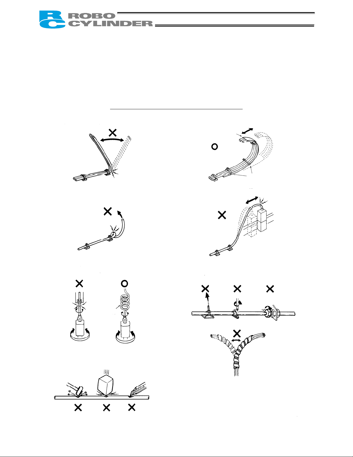
Ten Rules for Handling Cables (Must be Observed!)
1. Do not let the cable flex at a single point.
2. Do not let the cable bend, kink or twist.
Steel band
(piano wire)
3. Do not pull the cable with a strong force.
Bundle loosely.
4. Do not let the cable receive a turning force at a
single point.
6.
Do not pinch, drop a heavy object onto or cut
the cable.
Use a curly
cable.
5. When fixing the cable, provide a moderate slack
and do not tension it too tight.
Do not use a spiral tube where
the cable flexes frequently.
Page 10
A
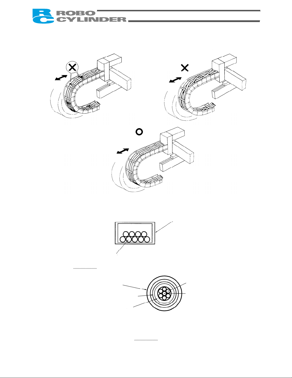
7. Do not let the cable get tangled or kinked in a cable bearer or flexible tube. When bundling the cable,
keep a certain degree of flexibility (so that the cable will not become too taut when bent).
8. Do not cause the cables to occupy more than 60% of the space in the cable bearer.
Do not place the connector in the cable bearer.
Cable
Cable bearer
9. Always use a robot cable if the cable is likely to flex significantly.
[Standard structure of cable]
The standard structure of
cable will vary depending on
the manufacturer and type of
cable.
Ì Need for Robot Cables
A cable connected to a moving part of an actuator system will inevitably receive repeated bending loads at
the base of the cable. As a result, the cores in the cable may break over time. To minimize the risk of
cable breakage, we strongly recommend that a robot cable
in this type of application.
Cover
Shield
Protective layer
offering significantly higher flexibility be used
Signal line (copper + tin)
bsorbing material (When the
cable is bent, this material is
crushed by the surrounding signal
lines to maintain the shape of the
signal lines.)
Page 11

Before Use
Caution
1. Be sure to read this operation manual to ensure the proper use of this product.
2. Unauthorized use or reproduction of a part or all of this operation manual is prohibited.
3. IAI shall not be liable whatsoever for any loss or damage arising from a handling or operation not
specified in this operation manual.
4. The information contained in this operation manual is subject to change without notice.
Action to Be Taken in Case of Emergency
* If this product is found to be in a dangerous condition, immediately turn off all power switches of the main unit
and connected equipment or immediately disconnect all power cables from the outlets. (“Dangerous
condition” refers to a situation where the product is generating abnormal heat or smoke or has ignited and a
fire or danger to human health is anticipated.)
Page 12

Table of Contents
1. Overview ................................................................................................. 1
1.1 Introduction ....................................................................................................................................... 1
1.2 Meaning of the Model Name ............................................................................................................ 2
1.3 Specifications.................................................................................................................................... 3
1.3.1 Correlation Diagrams of Speed and Load Capacity – Slider Type ........................................ 4
1.3.2 Correlation Diagrams of Speed and Load Capacity – Rod Type ........................................... 5
1.4 Safety Precautions............................................................................................................................ 7
1.5 Warranty Period and Scope of Warranty .......................................................................................... 8
1.6 Transportation and Handling ............................................................................................................ 9
1.6.1 Handling before Unpacking.................................................................................................... 9
1.6.2 Handling after Unpacking....................................................................................................... 9
1.7 Installation Environment and Noise Elimination ............................................................................. 10
1.7.1 Installation Environment....................................................................................................... 10
1.7.2 Storage Environment ........................................................................................................... 10
1.7.3 Power Supply........................................................................................................................11
1.7.4 Noise Elimination ..................................................................................................................11
1.8 Cabling............................................................................................................................................ 13
2. Installation ............................................................................................. 14
2.1 Name of Each Part ......................................................................................................................... 14
2.1.1 Slider Type (SA6/SA7)......................................................................................................... 14
2.1.2 Rod Type (RA54/RA64) ....................................................................................................... 14
2.1.3 (1) Rod Type with a Single Guide (RA54GS/RA64GS) ....................................................... 15
(2) Rod Type with Double Guides (RA54GD/RA64GD) ...................................................... 15
2.2 Installation....................................................................................................................................... 16
2.2.1 Slider Type ........................................................................................................................... 16
z Installing the actuator.............................................................................................................. 16
2.2.2 Rod Type.............................................................................................................................. 17
z Affixing with a flange ............................................................................................................... 17
z Affixing through holes in a flange............................................................................................ 17
z Affixing with foot brackets (optional) ....................................................................................... 18
2.2.3 Installing the Load................................................................................................................ 20
z Slider Type .............................................................................................................................. 20
z Rod Type................................................................................................................................. 21
z Rod type with a guide(s) ......................................................................................................... 21
3. Wiring.................................................................................................... 22
3.1 Basic Structure................................................................................................................................ 22
3.2 I/O Connections for PIO Pattern 1 [3 Points] (Air Cylinder)............................................................ 25
3.2.1 Explanation of I/O Signals.................................................................................................... 25
3.2.2 Details of Input Signals ........................................................................................................26
Movement to each position (ST0 to ST2) ............................................................................... 26
Page 13

Pause (*STP) .......................................................................................................................... 26
3.2.3 Details of Output Signals ..................................................................................................... 27
Completion of each position (PE0 to PE2) ............................................................................. 27
Alarm (*ALM)........................................................................................................................... 27
3.3
I/O Connections for PIO Pattern 0 [8 Points].................................................................................. 28
3.4 I/O Connections for PIO Pattern 2 [16 Points]................................................................................ 28
3.4.1 Explanation of I/O Signals.................................................................................................... 29
3.4.2 Details of Input Signals ........................................................................................................29
Start (CSTR)............................................................................................................................ 29
Command position number (PC1 to PC8) .............................................................................. 30
Pause (*STP) .......................................................................................................................... 30
Home return (HOME)..............................................................................................................30
3.4.3 Details of Output Signals ..................................................................................................... 30
Position complete (PEND) ...................................................................................................... 30
Home return completion (HEND) ............................................................................................ 31
Zone (ZONE)........................................................................................................................... 31
Alarm (*ALM)........................................................................................................................... 31
3.5 Configuration Using a SIO Converter .............................................................................................32
3.6 Configuration Using an Insulated PIO Terminal Block.................................................................... 36
3.7 Configuration Using Both SIO Converter and Insulated PIO Terminal Block................................. 40
3.8 Controlling Multiple Axes via Serial Communication ...................................................................... 43
3.8.1 Basic Specifications ............................................................................................................. 43
3.8.2 Address Assignment ............................................................................................................ 43
3.8.3 Wiring Examples for Linking Multiple Axes .......................................................................... 44
z Using only a SIO converter ..................................................................................................... 44
z Using both SIO converter and insulated PIO terminal block .................................................. 45
3.9
Emergency-Stop Circuit.................................................................................................................. 46
3.10 Relay Cable.................................................................................................................................... 48
4. Electrical Specifications......................................................................... 50
4.1 Controller ........................................................................................................................................ 50
4.2 I/O Signal Interface Circuit.............................................................................................................. 51
4.2.1 External Input Specifications................................................................................................ 51
4.2.2 External Output Specifications............................................................................................. 52
4.3 SIO Converter (Optional)................................................................................................................ 53
4.4 Insulated PIO Terminal Block (Optional).........................................................................................55
5. Data Entry <Basics>.............................................................................. 61
5.1 Description of Position-Data Table.................................................................................................. 62
5.1.1 Relationship of Push Force at Standstill and Current-Limiting Value .................................. 64
5.2 Explanation of Modes ..................................................................................................................... 66
5.2.1 Positioning Mode ................................................................................................................. 66
5.2.2 Push & Hold Mode ............................................................................................................... 66
5.2.3 Speed Change during Movement ........................................................................................ 68
5.2.4 Operation at Different Acceleration and Deceleration Settings ........................................... 68
Page 14

5.2.5
Pause ................................................................................................................................... 69
5.2.6 Zone Signal Output ..............................................................................................................69
5.2.7 Home Return........................................................................................................................ 69
6. Operation in the “3 Points (Air Cylinder)” Mode <Practical Operation>. 70
6.1 Overview of the “3 Points” Mode .................................................................................................... 70
6.2 How to Start .................................................................................................................................... 72
6.3 Moving Operation ........................................................................................................................... 74
7. Operation in the “8 Points” and “16 Points” Modes
<Practical Operation> ........................................................................... 78
7.1 How to Start .................................................................................................................................... 78
7.2 How to Execute Home Return ........................................................................................................ 80
7.2.1 8 Points ................................................................................................................................ 80
7.2.2 16 Points .............................................................................................................................. 81
7.3 Home Return and Movement after Start (16 Points) ...................................................................... 82
7.4 Positioning Mode (Back and Forth Movement between Two Points) ............................................. 84
7.5 Push & Hold Mode.......................................................................................................................... 86
7.5.1 Return Action after Push & Hold by Relative Coordinate Specification ............................... 87
7.6 Speed Change during Movement................................................................................................... 88
7.7 Operation at Different Acceleration and Deceleration Settings ...................................................... 90
7.8 Pause.............................................................................................................................................. 92
7.9 Zone Signal Output......................................................................................................................... 94
7.10 Incremental Moves......................................................................................................................... 96
7.11 Notes on Incremental Mode........................................................................................................... 98
8. Parameters.......................................................................................... 100
8.1 Parameter Classification............................................................................................................... 100
8.2 Parameter Table ........................................................................................................................... 100
8.3 Parameter Settings ....................................................................................................................... 101
8.3.1 Parameters Relating to the Actuator Stroke Range........................................................... 101
z Soft limit ................................................................................................................................ 101
z Zone boundary ...................................................................................................................... 101
z Home return direction ........................................................................................................... 102
z Home return offset ................................................................................................................ 102
8.3.2 Parameters Relating to the Actuator Operating Characteristics........................................ 102
z Default speed ........................................................................................................................ 102
z Default acceleration/deceleration.......................................................................................... 102
z Default positioning band (in-position) ................................................................................... 102
z Default acceleration only MAX flag ....................................................................................... 103
z Push & hold stop judgment period ........................................................................................ 103
z Current-limiting value at standstill during positioning............................................................ 103
z Current-limiting value during home return ............................................................................ 104
8.3.3 Parameters Relating to the External Interface................................................................... 104
z PIO pattern selection ............................................................................................................ 104
z Movement command type..................................................................................................... 104
Page 15

z Pause input disable selection ............................................................................................... 105
z Serial communication speed................................................................................................. 105
z Minimum delay time for slave transmitter activation ............................................................. 105
8.3.4 Servo Gain Adjustment ...................................................................................................... 106
z Servo gain number................................................................................................................ 106
9. Troubleshooting................................................................................... 107
9.1 Action to Be Taken upon Occurrence of Problem......................................................................... 107
9.2 Alarm Level Classification ............................................................................................................ 107
9.3 Alarm Description and Cause/Action............................................................................................ 108
(1) Message level alarms ........................................................................................................... 108
(2) Operation-cancellation level alarms...................................................................................... 109
(3) Cold-start level alarms ...........................................................................................................110
9.4 Messages Displayed during Operation Using the Teaching Pendant or PC Software.................. 111
9.5 Specific Problems ..........................................................................................................................113
z I/O signals cannot be exchanged with the PLC. ....................................................................113
z The LED lamp does not illuminate after the power is input. ..................................................113
z The LED illuminates in red when the power is turned on. .....................................................113
z Home return ends in the middle in a vertical application. ......................................................113
z Noise occurs during downward movements in a vertical application. ...................................113
z Vibration occurs when the actuator is stopped. .....................................................................114
z The actuator overshoots when decelerated to a stop............................................................114
z The home and target positions sometimes shift on the rod-type actuator.............................114
z The speed is slow during push & hold operation. ..................................................................114
z The actuator operates abnormally when the servo is turned on following the power
on. ..........................................................................................................................................114
10. Maintenance and Inspection ............................................................... 115
10.1 Inspection Items and Timings .......................................................................................................115
10.2 Visual Inspection of Appearance...................................................................................................115
10.3 Cleaning ........................................................................................................................................115
10.4 Internal Check (Slider Type)..........................................................................................................116
10.5 Internal Cleaning (Slider Type) .....................................................................................................117
10.6 Greasing the Guide (Slider Type) .................................................................................................117
10.7 Greasing the Ball Screw (Slider Type)..........................................................................................119
10.8 Greasing the Rod Slide Surface .................................................................................................. 120
10.9 Motor Replacement Procedure .................................................................................................... 121
* Appendix ................................................................................................ 123
Example of Basic ERC Positioning Sequence....................................................................................... 123
Recording of Position-Data Table .......................................................................................................... 126
Parameter Records................................................................................................................................ 127
Page 16

1. Overview
1.1 Introduction
Thank you for purchasing the Easy All-in-One Robo Cylinder (hereinafter referred to as “ERC”). This
manual explains the features and operating procedures of the product.
If not used or handled properly, even a brilliant product cannot fully demonstrate its function or may cause
an unexpected breakdown or end its life prematurely. Please read this manual carefully and handle the
product with utmost care while ensuring its correct operation. Keep this manual in a convenient place so
the relevant sections can be referenced readily when necessary.
If you are also using the optional PC software or teaching pendant, also refer to the operation manual for
the applicable item.
* We have made every effort to ensure accuracy of the information provided in this manual. Should you
find an error, however, or if you have any comment, please contact IAI.
Keep this manual in a convenient place so it can be referenced readily when necessary.
1
Page 17
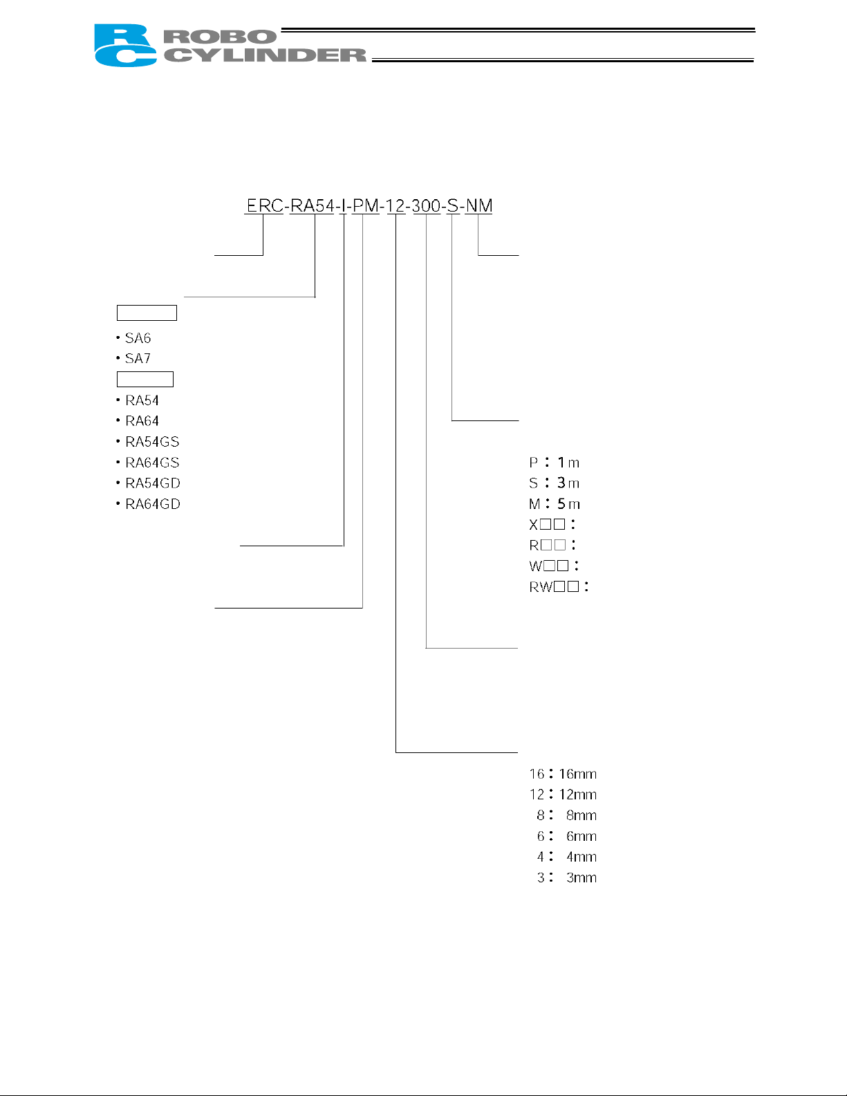
1.2 Meaning of the Model Name
<Series name>
<Type>
Slider type
Rod type
<Encoder type>
I: Incremental
<Motor type>
PM: Pulse motor
<Options>
Blank: No option
B: With brake
NM: Reversed-home specification
FT: Foot bracket (Specified only
for rod types.)
EN: CE-compliant NPN
specification
EP: CE-compliant PNP
specification
<Relay cable length>
Blank: No cable
Length specification (Example) X08 = 8 m
Robot cable specification
Connectors on both ends
<Stroke>
50 to 600 mm
(Standard lengths are multiples of 50 mm.)
(Example) 100 = 100 mm
Robot cable / Connectors on both
ends
<Ball screw lead>
2
Page 18

1.3 Specifications
Model
Stroke (mm) and maximum speed (mm/sec) (Note 1)
Slider type
Rod type
(Note 1) The figures in blank bands indicate the maximum speeds for respective strokes. The maximum speeds
during vertical operation are shown in parentheses.
(Note 2) The load capacity is based on operation at the rated acceleration. In the case of a guide type, find the
applicable load capacity in the above table and subtract the weight of the guide to obtain the effective load
capacity.
Load capacity (Note 2)
Horizontal
Vertical
Rated acceleration
Horizontal
Vertical
3
Page 19
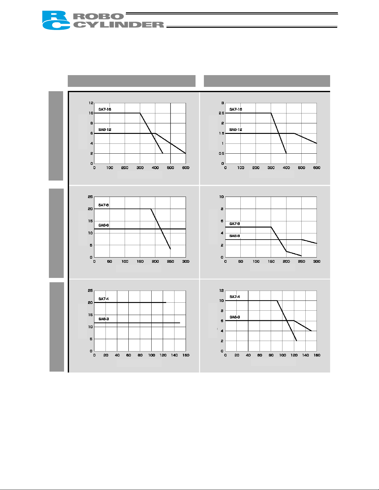
1.3.1 Correlation Diagrams of Speed and Load Capacity – Slider Type
High-speed type
Medium-speed type
Low-speed type
(Note) In the above graphs, the number after each type name indicates the lead.
Horizontal installation Vertical installation
Load capacity (kg)
Speed (mm/sec)
Load capacity (kg)
Speed (mm/sec)
Load capacity (kg)
Speed (mm/sec)
Load capacity (kg)
Load capacity (kg)
Load capacity (kg)
Speed (mm/sec)
Speed (mm/sec)
Speed (mm/sec)
4
Page 20
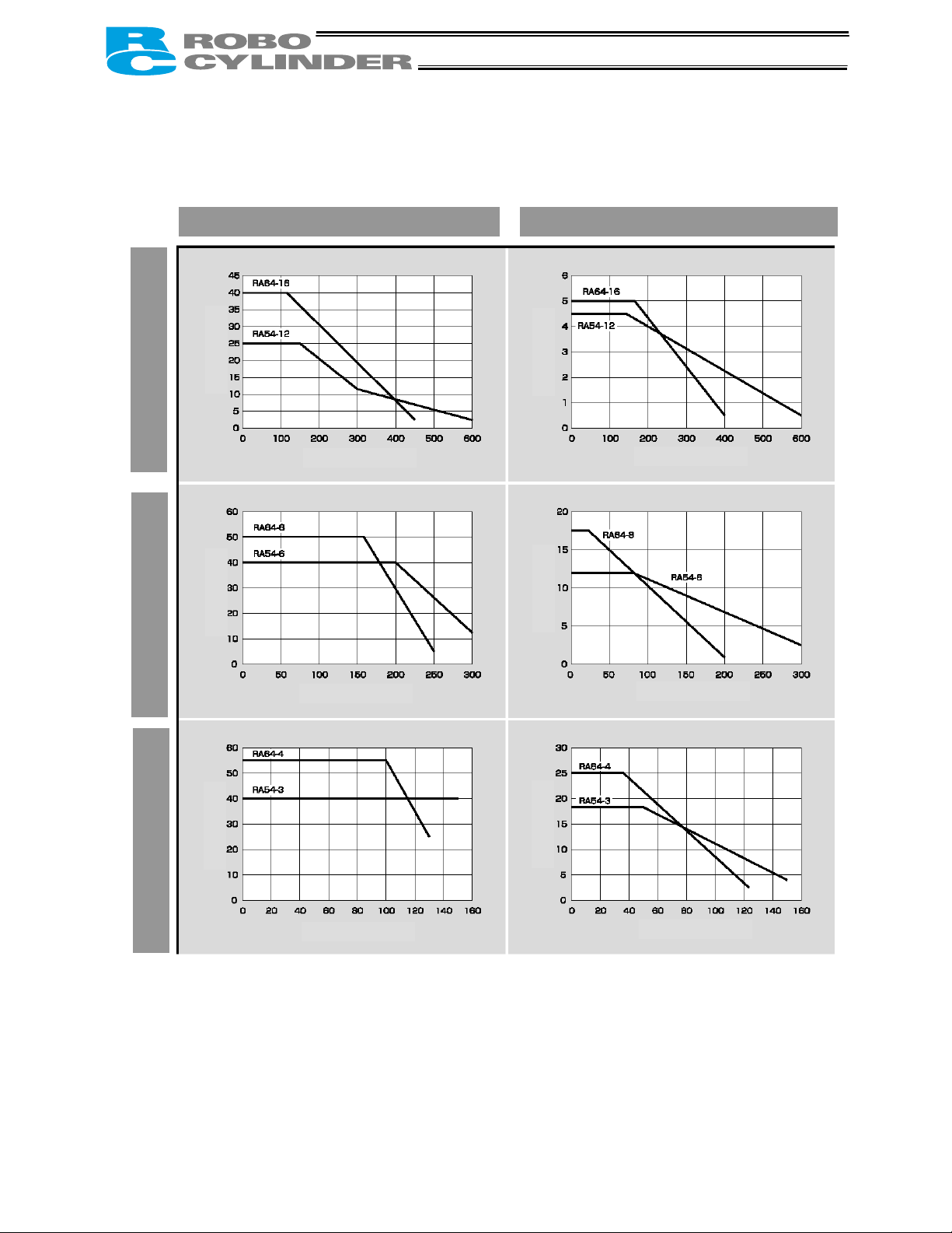
1.3.2 Correlation Diagrams of Speed and Load Capacity – Rod Type
High-speed type
Medium-speed type
Low-speed type
(Note) In the above graphs, the number after each type name indicates the lead.
Horizontal installation Vertical installation
Load capacity (kg)
Speed (mm/sec)
Load capacity (kg)
Speed (mm/sec)
Load capacity (kg)
Speed (mm/sec)
Load capacity (kg)
Speed (mm/sec)
Load capacity (kg)
Load capacity (kg)
Speed (mm/sec)
Speed (mm/sec)
5
Page 21

Load Applied to the Actuator
(1) Slider type
• Keep the load applied to the slider below the value stated in the applicable specification item.
In particular, pay attention to the moment applied to the slider, allowable overhung length and load
capacity.
• If the slider is used in an overhung application with the load extending in the Y-axis direction, keep
moments Ma and Mc to one-half the rated moment or less to prevent the base from deforming.
(2) Rod type
• Keep the load applied to the rod below the value specified in the catalog.
• Make sure the center of the rod axis corresponds to the moving direction of the load.
• Application of lateral load may cause an actuator damage or breakdown.
• If the rod is to be subjected to lateral load, provide a guide or other support in
the moving direction of the load.
• Do not apply rotating torque to the rod (slide shaft).
* It will result in internal damages.
When tightening the nut at the tip of the rod, secure the rod using a
wrench of size 13 (RA54 type) or 17 (RA64 type).
6
Page 22

1.4 Safety Precautions
Read the following information carefully and provide safety measures with due consideration.
This product has been developed as a drive component for automated machinery and the like, and is
therefore designed not to generate excessive torque or speed beyond the levels needed to drive
automated equipment. However, the following instructions must be strictly observed to prevent an
unexpected accident.
1. Assume that the product cannot be handled or operated in any manner not specified in this manual,
and do not attempt any such handling or operation.
2. Do not enter the operating range of the machine while the machine is operating or is able to operate
(the controller power is ON). If the machine is used in a place accessible to other people, enclose its
operating range using a safety cage, etc.
3. Always turn off the power supply to the controller before assembling/adjusting or
maintaining/inspecting the machine. During assembly/adjustment or maintenance/inspection, put a
plate or other visible sign in a conspicuous place indicating that work is in progress. Provide sufficient
safety measures to prevent another person from inadvertently plugging in the cable during work.
4. If two or more persons work together, set signaling methods so each person can confirm the safety of
other(s) during work. Especially when the work requires an axis or axes to be moved—with or without
the power and by motor drive or manual operation—the person moving each axis should always call
out beforehand to ensure safety.
7
Page 23

1.5 Warranty Period and Scope of Warranty
The ERC you have purchased passed IAI’s shipping inspection implemented under the strictest
standards. The unit is covered by the following warranty:
1. Warranty Period
The warranty period shall be one of the following periods, whichever ends first:
• 18 months after shipment from our factory
• 12 months after delivery to a specified location
2. Scope of Warranty
If an obvious manufacturing defect is found during the above period under an appropriate condition of
use, IAI will repair the defect free of charge. Note, however, that the following items are excluded from
the scope of warranty:
• Aging such as natural discoloration of coating
• Wear of a consumable part due to use
• Noise or other sensory deviation that doesn’t affect the mechanical function
• Defect caused by inappropriate handling or use by the user
• Defect caused by inappropriate or erroneous maintenance/inspection
• Defect caused by use of a part other than IAI’s genuine part
• Defect caused by an alteration or other change not approved by IAI or its agent
• Defect caused by an act of God, accident, fire, etc.
The warranty covers only the product as it has been delivered and shall not cover any losses arising in
connection with the delivered product. The defective product must be brought to our factory for repair.
Please read the above conditions of warranty carefully.
8
Page 24

1.6 Transportation and Handling
1.6.1 Handling before Unpacking
Exercise due caution when transporting or handling the box containing the actuator, by not applying
impact on the box as a result of collision or dropping.
• If the box is heavy, one person should not carry it by himself.
• Place the box in a level surface.
• Do not step on the box.
• Do not place on the box any heavy object that may cause the box to deform or other object with a
section where loads will concentrate.
1.6.2 Handling after Unpacking
Once removed out of the box, hold the actuator by the frame if it is a rod type, or by the base if it is a slider
type.
• When carrying the actuator, be careful not to allow it to collide with other objects. In particular, pay
attention to the front bracket, motor bracket and motor cover.
• Do not exert excessive force on each part of the actuator. In particular, pay attention to the motor cover
and cables.
• When unpacking, exercise due caution not to let the actuator drop and sustain damage to its
mechanism.
• If the actuator is damaged during the shipment or any of the items is found missing, please contact IAI’s
Technical Support immediately.
Supplement) Refer to 2.1, “Name of Each Part,” for the name of each part of the actuator.
9
Page 25

1.7 Installation Environment and Noise Elimination
Pay due attention to the installation environment of the controller.
1.7.1 Installation Environment
The installation environment must satisfy the following conditions:
No. Use environment/condition
[1] Not exposed to direct sunlight.
The actuator is not subject to irradiated heat from a large heat source, such as a heat
[2]
treatment furnace.
[3]
Ambient temperature of 0 to 40°C.
[4] Humidity of 85% or less without condensation.
[5] Not exposed to corrosive or flammable gases.
[6] Normal environment for assembly and operation not subject to significant dust.
[7] Not exposed to oil mist or cutting fluid.
[8] Not subject to vibration exceeding 0.3 G.
[9] Not exposed to strong electromagnetic waves, ultraviolet light or radiation.
[10] Chemical resistance is not considered at all in the design of this product.
[11] The actuator and cables are not subject to electrical noise.
In general, the installation environment shall be such that the operator can work without wearing any
protective gears.
1.7.2 Storage Environment
The storage environment shall conform to the installation environment, but special caution is required to
prevent condensation if the actuator is to be stored for a long period of time.
Unless otherwise specified, the actuator is shipped without any desiccating agent placed in the box. If the
actuator is to be stored in an environment subject to condensation, provide a non-condensing measure
from outside the box or directly inside the box.
The actuator is designed to withstand storage temperatures of up to 60°C for a short period of time. If the
storage period will extend beyond one month, however, keep the ambient temperature below 50°C.
10
Page 26
1.7.3 Power Supply
The control/motor-drive power supply specification is 24 VDC ± 10% (2 A max).
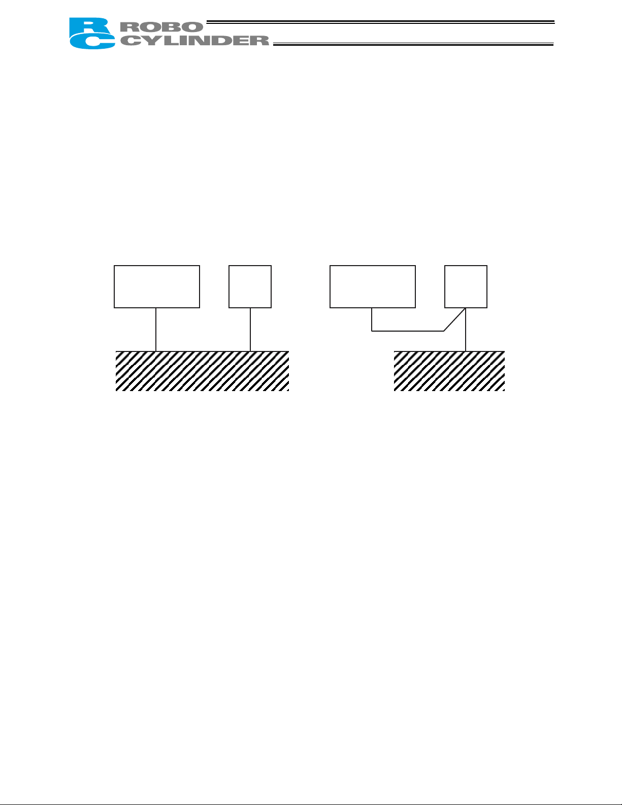
1.7.4 Noise Elimination
This section explains how to eliminate noise in the use of the controller.
(1) Wiring and power supply
[1] Provide a dedicated class D grounding using a wire with a size of 0.75 mm
Actuator with
integrated
controller
Other
equipment
Actuator with
integrated
controller
Class D grounding Good Avoid this grounding method.
[2] Precautions regarding wiring method
Separate the controller cables from high-power lines such as a cable connecting to a power circuit.
(Do not bundle together the controller cables with high-power lines or place them in the same cable
duct.)
2
or larger.
Other
equipment
11
Page 27
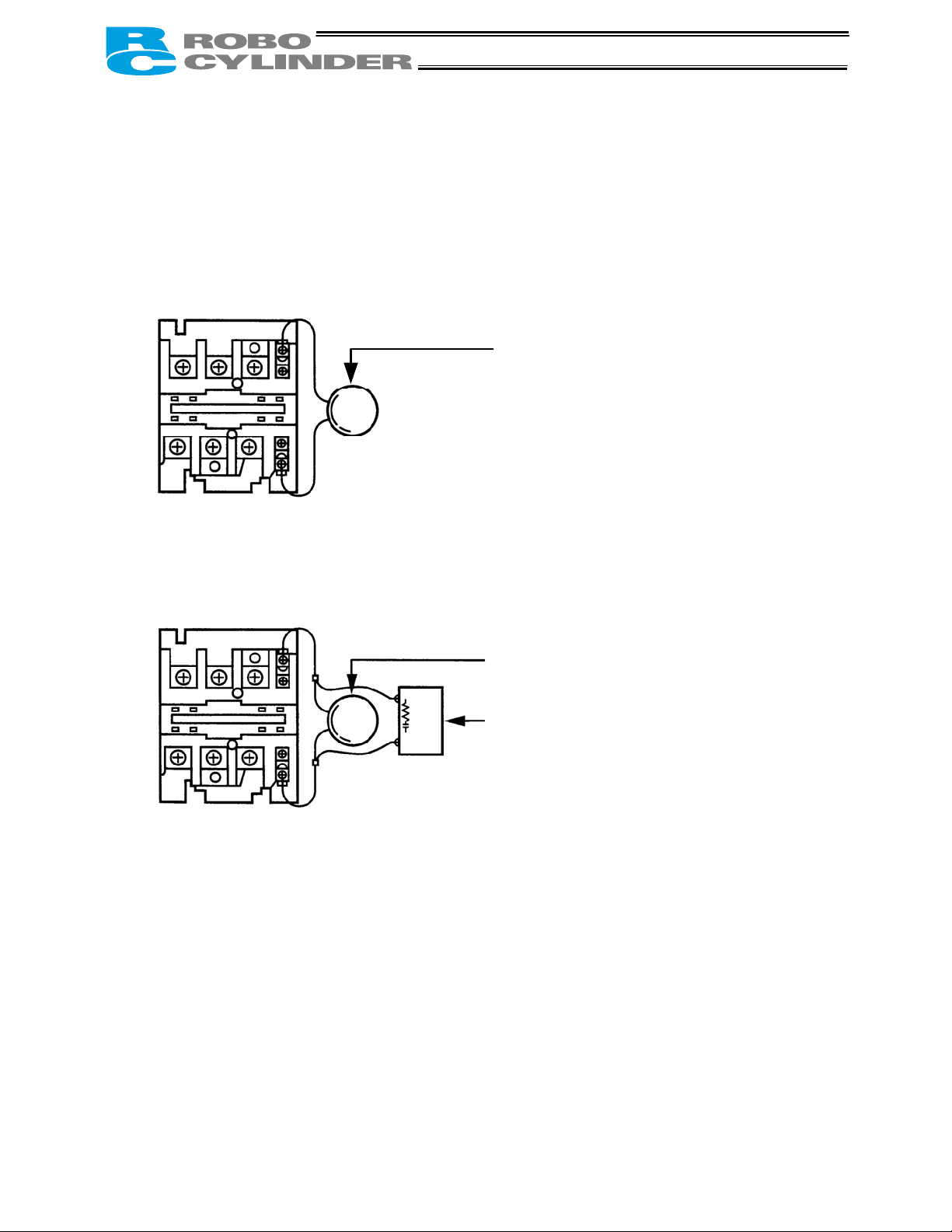
(2) Noise sources and elimination
Among the numerous noise sources, solenoid valves, magnet switches and relays are of particular
concern when building a system. Noise from these sources can be eliminated by implementing the
measures specified below.
[1] AC solenoid valves, magnet switches and relays
Measure: Install a surge absorber in parallel with the coil.
The most effective method is to connect a surge absorber and a surge killer in parallel.
This way, noise will be eliminated in the entire range.
Å Point
Install a surge absorber to each coil over a minimum wiring length.
Installing a surge absorber to the terminal block or other part will
be less effective because of a longer distance from the coil.
Surge absorber
Surge absorber
Surge killer (CR set)
12
Page 28
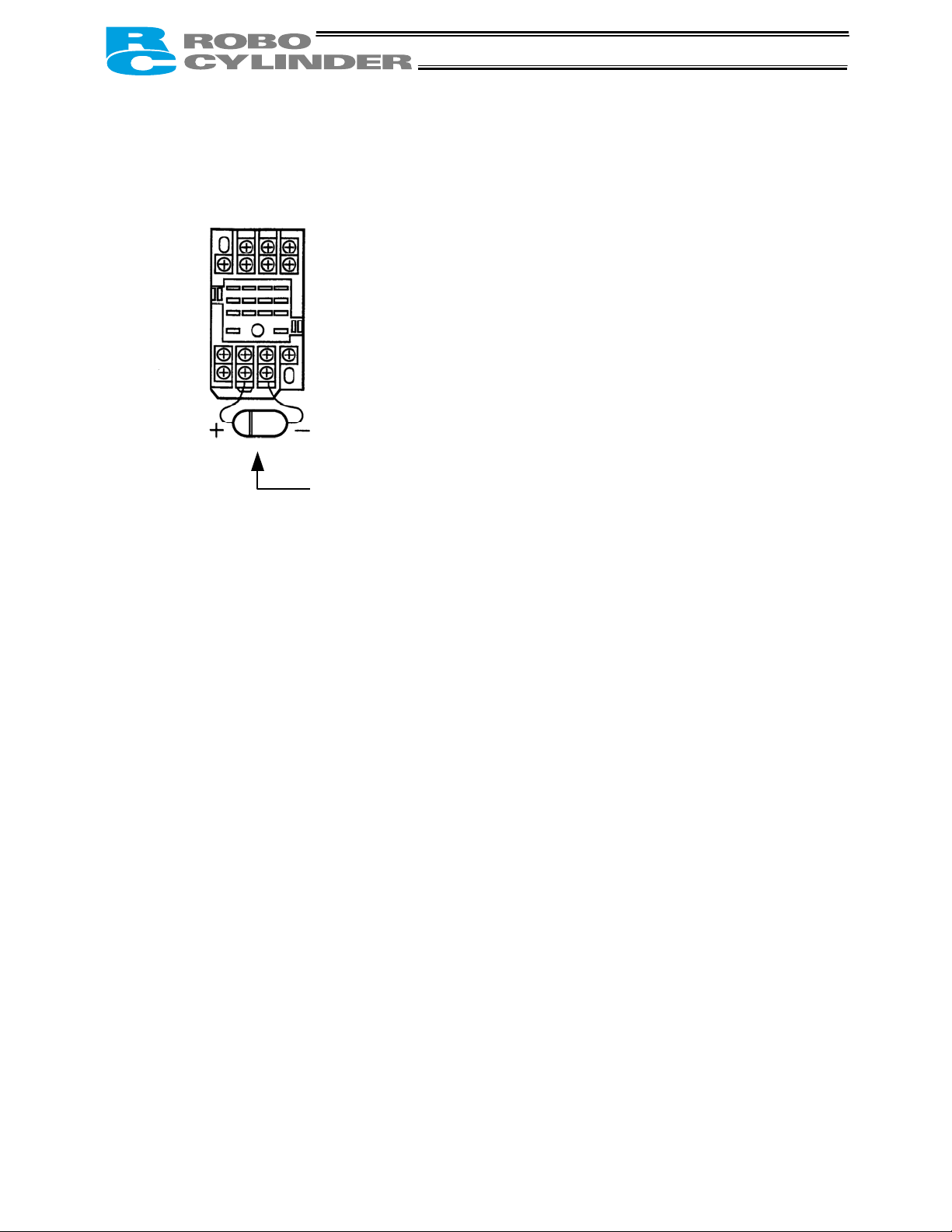
[2] DC solenoid valves, magnet switches and relays
Measure: Install a diode in parallel with the coil. Determine the diode capacity in accordance with the
load capacity.
Diode
In a DC circuit, connecting a diode in reverse polarity will damage
the diode, internal parts of the controller and/or DC power supply,
so exercise due caution.
1.8 Cabling
• The standard relay cables have excellent flexibility to withstand fatigue from flexural loads, but they are
not robot cables. Therefore, avoid storing the standard relay cables in movable cable ducts laid at a
small radius. If they must be stored in movable cable ducts, use robot cables.
• In an application where the cable cannot be fixed, keep the cable from receiving a deflecting load
exceeding its own weight, use a self-standing cable hose, provide a large bending radius along the
wiring path, or provide other measure to minimize the load applied to the cable.
• Do not cut the cable for the purpose of extension, length reduction or reconnection.
If you intend to change the cable layout, please consult IAI.
13
Page 29
r
2. Installation
2.1 Name of Each Part
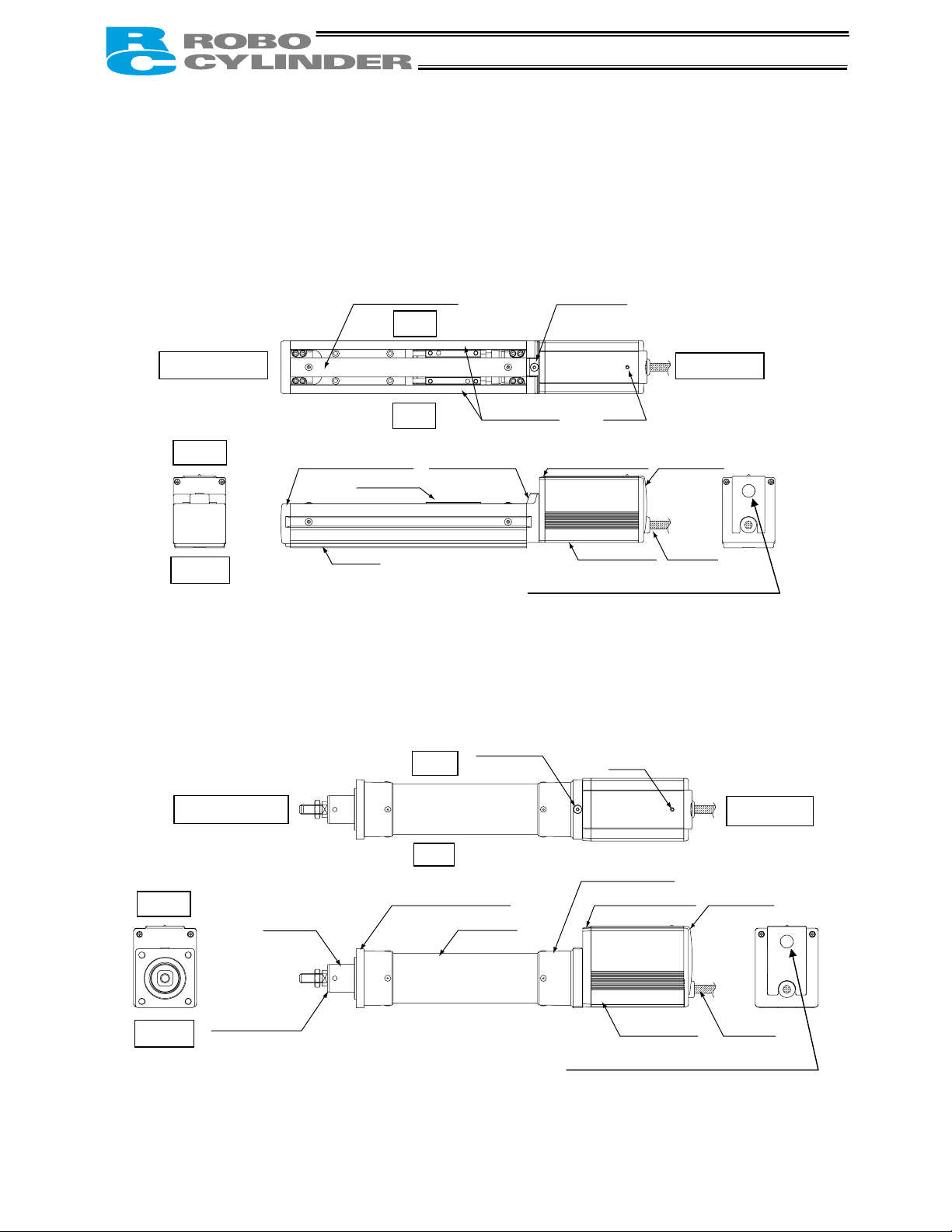
2.1.1 Slider Type (SA6/SA7)
Non-motor end
Top
Front bracket
Bottom
2.1.2 Rod Type (RA54/RA64)
Top
Bottom
Non-motor end
Rod
Rod end bracket
Screw cover Coupling bolt
Slider
Base
Right
Left
Rear bracket
Right
Left
Front bracket
Frame
Motor end
Side cove
Motor bracket
Connection port for teaching pendant or PC
(The arrow on the connector should face down.)
Coupling bolt
Connection port for teaching pendant or PC
(The arrow on the connector should face down.)
LED
Rear cover
Motor cover
LED
Rear bracket
Motor bracket
Motor cover Cable
Cable
Motor end
Rear cover
14
Page 30
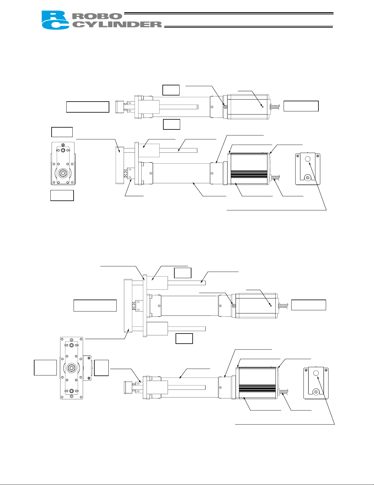
2.1.3 (1) Rod Type with a Single Guide (RA54GS/RA64GS)
Right
Coupling bolt
Non-motor end
Top
Guide bracket Guide bearing
Left
Guide rod
Rear bracket
Motor bracket
Bottom
Rod
Frame
Connection port for teaching pendant or PC
(The arrow on the connector should face down.)
2.1.3 (2) Rod Type with Double Guides (RA54GD/RA64GD)
Bottom
Mounting bracket
Non-motor end
Guide bracket
Top
Rod
Guide bearing
Guide rod
Right
Coupling bolt
Left
Rear bracket
Frame
Connection port for teaching pendant or PC
(The arrow on the connector should face down.)
LED
Motor cover
LED
Motor bracket
Motor cover
Motor end
Rear cover
Cable
Motor end
Rear cover
Cable
15
Page 31

2.2 Installation
2.2.1 Slider Type
z Installing the actuator
The actuator-mounting surface must be a machined surface or have an equivalent flatness.
The side and bottom faces of the actuator base are parallel with the guides. If high slide accuracy is
required, install the actuator by using these surfaces as references.
(Note) Reduced flatness due to installation of an overhung load will cause the base to deform and inhibit
smooth movement of the slider. If the slider movement becomes heavier on the motor end or the
slider begins generating noise, correct the flatness. Otherwise, the slider mechanism may end its
life prematurely.
Slider type
Install the actuator in the mounting holes provided in the
base. Secure the actuator in place using M4 hex cap bolts.
16
Page 32

2.2.2 Rod Type
A rod-type actuator can be installed in the following two ways:
z Affixing with a flange
Install the actuator by tightening from the motor end side with hex cap bolts using the holes provided in the
flange.
Caution: If the actuator is installed horizontally,
exercise caution not to let the actuator
receive excessive forces.
Hex cap bolt
Hole in flange
Flange tightening bolts
Model Nominal thread size Tightening torque
z Affixing through holes in a flange
RA54 M5 3.4 Nm (0.35 kgfm)
RA64 M6 5.4 Nm (0.55 kgfm)
Caution: If the actuator is installed horizontally,
exercise caution not to let the actuator
receive excessive forces.
Flange tightening bolts
Model Nominal thread size Tightening torque
RA54GD M5
Steel bolt-bearing surface: 7.3 N•m
Aluminum bolt-bearing surface: 3.4 N•m
Hex cap bolt
RA64GD
M6
Steel bolt-bearing surface: 12.3 N•m
Aluminum bolt-bearing surface: 5.4 N•m
17
Page 33

z Affixing with foot brackets (optional)
If optional foot brackets are used, install the foot brackets using hex cap bolts.
Foot-bracket tightening bolts
Model Nominal thread size Tightening torque
RA54
RA54GS
M6 5.4 Nm (0.55 kgfm)
RA54GD
RA64
RA64GS
M8 11.5 Nm (1.17 kgfm)
RA64GD
18
Page 34

19
Page 35

2.2.3 Installing the Load
z Slider Type
Four tapped holes are provided in the slider,
so affix the load using these holes (indicated
by arrows in the figure shown to the left).
Type Slider mounting hole
SA6, SA7 M5, depth 9 mm
Nominal thread size Tightening torque
Bolt bearing surface: steel Bolt bearing surface: aluminum
M5 7.3 Nm (0.74 kgfm) 3.4 Nm (0.35 kgfm)
The affixing method of the load shall conform to the installation method of the actuator.
In an application where the actuator is moved with the slider fixed, install the load using the tapped holes
in the slider in the same manner.
The slider has two reamed holes. Use these holes when high repeatability is required for load
installation/removal. When fine-tuning the squareness of the load, etc., make adjustment by using one of
these two reamed holes in the slider.
Type Reamed hole
SA6, SA7
φ5, H10, depth 10 mm
20
Page 36

z Rod Type
A bolt is attached on the rod end bracket, so use this bolt to affix the load. (Use the supplied nut, if
necessary.)
Rod end bracket
Model Rod end bracket
RA54 M8, length 18 mm
RA64 M10, length 21 mm
Note) Apply a spanner at the rod end bracket to
prevent the rod from receiving any rotating
moment when the load is installed.
Applying excessive rotating moment to the
rod may damage the rod.
RA54: Width across flats 13 mm
RA64: Width across flats 17 mm
z Rod type with a guide(s)
Tapped holes are provided in the guide bracket. Affix the work
using these holes (shown by the arrows in the figures at left).
Model Nominal thread size
RA54GS M5
Single guide
RA54GD
RA64GS M6
M5
RA64GD M6
Tightening torque
Nominal thread size
Bolt bearing surface:
steel
Bolt bearing surface:
aluminum
M5 7.3 Nxm (0.74 kgfxm) 3.4 Nxm (0.35 kgfxm)
Double guides
M6
12.3 Nxm (1.26 kgfxm) 5.4 Nxm (0.55 kgfxm)
21
Page 37

←
3. Wiring
3.1 Basic Structure
Host system <PLC>
ERC actuator
Teaching pendant
<RCA-T>
Optional
Cable length: 5 m
Relay cable
<RCB-101-MW>
Standard cable <CB-ERC-PWBIO * * *>
Robot cable <CB-ERC-PWBIO * * *-RB>
Cable length: 1 m, 3 m, 5 m
PIO
24-VDC control/motor power supply (2 A or more)
Brake release switch
Emergency-stop/motor-power cutoff circuit
Drain wire
SIO →
PC software
Optional
PERSONAL
COMPUTER
(Not used)
22
Page 38

x
z Connection diagram
[1] When the control board is of the NPN specification [sink type]
Input power supply
(2 A or more)
24V
0V
FG
EMG signal
Brake release
switch
MC
60 mA ma
(Note)
*Light blue (Red 1)
*Light blue (Black 1)
Yellow (Red 1)
Yellow (Black 1)
Pink (Red 1)
Pink (Black 1)
White (Red 1)
White (Black 1)
CN1
2A EMS1
2B EMS2
4A MPI
4B GND
5A MPI
5B GND
3A 24V
3B BKR
Host system
<PLC>
side
Output
side
Input
(Not used)
Orange (Red 2)
Orange (Black 2)
*Light blue (Red 2)
*Light blue (Black 2)
White (Red 2)
White (Black 2)
Yellow (Red 2)
Yellow (Black 2)
Pink (Red 2)
Pink (Black 2)
Orange (Red 1)
Orange (Black 1)
CN2
FG
6A
6B
7A
7B
8A
8B
9A
9B
10A
10B
1A SGA Serial communication
1B SGB
Drain wire
* In the case of a robot cable, the wire colors change as follows.
Wire color Pin number
Gray (Red 1) 2A
Gray (Black 1) 2B
Gray (Red 2) 7A
Gray (Black 2) 7B
(Note) To release the brake, connect a switch between BKR and 0 V and turn on the switch.
ERC actuator
Contact output for EMG
switch on teaching pendant
Motor drive power supply
Control power supply
OFF when the brake is
controlled by the controller, or
ON when the brake is released
(Applicable to an actuator with
brake)
I/O interface
(Refer to the I/O connections for each
PIO pattern)
23
Page 39

x
[2] When the control board is of the PNP specification [source type]
ERC actuator
Input power supply
(2 A or more)
24V
0V
FG
EMG signal
Brake release
switch
Host system
<PLC>
MC
(Note)
Output
Input
60 mA ma
side
side
*Light blue (Red 1)
*Light blue (Black 1)
Yellow (Red 1)
Yellow (Black 1)
Pink (Red 1)
Pink (Black 1)
White (Red 1)
White (Black 1)
Orange (Red 2)
Orange (Black 2)
*Light blue (Red 2)
*Light blue (Black 2)
White (Red 2)
White (Black 2)
Yellow (Red 2)
Yellow (Black 2)
Pink (Red 2)
Pink (Black 2)
CN1
2A EMS1
2B EMS2
4A MPI
4B GND
5A MPI
5B GND
3A 24V
3B BKR
6A
6B
7A
7B
8A
8B
9A
9B
10A
10B
Contact output for EMG
switch on teaching pendant
Motor drive power supply
Control power supply
OFF when the brake is
controlled by the controller, or
ON when the brake is released
(Applicable to an actuator with
brake)
I/O interface
(Refer to the I/O connections for each
PIO pattern)
(Not used)
Orange (Red 1)
Orange (Black 1)
CN2
FG
1A SGA Serial communication
1B SGB
Drain wire
* In the case of a robot cable, the wire colors change as follows.
Wire color Pin number
Gray (Red 1) 2A
Gray (Black 1) 2B
Gray (Red 2) 7A
Gray (Black 2) 7B
(Note) To release the brake, connect a switch between BKR and 24 V and turn on the switch.
24
Page 40

3.2 I/O Connections for PIO Pattern 1 [3 Points] (Air Cylinder)
The following description assumes that the ERC is used in the place of an air cylinder.
The number of positioning points is limited to three, but a direct command input and a position complete
output are provided separately for the target position in line with the conventional practice of air cylinder
control.
Note: The factory setting is “8 points,” so set parameter No. 25 to “1.” The pause signal can be
disabled in parameter No. 15.
Host system <PLC>
Rear end move
Front end move
Output
Intermediate point
move
side
Pause
Rear end complete
Input
Front end complete
side
Intermediate point
complete
Alarm
3.2.1 Explanation of I/O Signals
Category Signal name
Rear end move ST0 The actuator starts moving to the rear end at the rise edge of the signal.
Signal
abbreviation
Orange (Red 2)
Orange (Black 2)
*Light blue (Red 2)
*Light blue (Black 2)
White (Red 2)
White (Black 2)
Yellow (Red 2)
Yellow (Black 2)
Pink (Red 2)
Pink (Black 2)
ERC actuator end
CN1 (Signal abbreviation)
6A ST0
6B ST1
* Robot cable
7A ST2
Gray (Red 2)
Gray (Black 2)
7B
8A
8B *STP
9A PE0
9B PE1
10A PE2
10B *ALM
(Note) *STP and *ALM are always ON.
Function overview
Input
Output
Front end move ST1 The actuator starts moving to the front end at the rise edge of the signal.
Intermediate
point move
*Pause *STP ON: The actuator can be moved, OFF: The actuator decelerates to a stop
Rear end
complete
Front end
complete
Intermediate
point complete
*Alarm *ALM
ST2
PE0 The signal turns ON when the actuator completes moving to the rear end.
PE1 The signal turns ON when the actuator completes moving to the front end.
PE2
The actuator starts moving to the intermediate point at the rise edge of the
signal.
The signal turns ON when the actuator completes moving to the intermediate
point.
This signal remains ON while the controller is operating properly, and turns
OFF when an alarm generates.
The *ALM signal is synchronized with the green/red indication of the LED.
(Note) The signal remains ON while the motor drive power is cut off.
25
Page 41

r
3.2.2 Details of Input Signals
The input signals from this controller have an input time constant, in order to prevent malfunction caused
by chattering, noise, etc.
Each input signal will switch the applicable setting when received continuously for 6 msec or more.
In other words, when a given input is switched from OFF to ON, the controller will recognize the ON state
of the signal only after elapse of 6 msec.
The same applies to the switching of an input from ON to OFF. (Fig. 1)
Recognition by the controlle
Movement to each position (ST0 to ST2)
When the OFF Æ ON rise edge of each movement signal is detected, the actuator will move to the target
position corresponding to the applicable position data.
Before executing a command using any of these signals, make sure the target position, speed and other
operation data are set in the position table using a PC or teaching pendant.
Rear end move (ST0) 0 Set the rear end position in position No. 0.
Input signal
Input signal
Not recognized Not recognized
6 [msec] 6 [msec]
Fig. 1 Recognition of Input Signal
Corresponding
position number
Remarks
Front end move (ST1) 1 Set the front end position in position No. 1.
Intermediate point 1 move (ST2) 2 Set the intermediate point in position No. 2.
If a movement command is issued when the first home return is not yet completed after the power was
input, home return will be performed automatically to establish the coordinates first, after which the
actuator will move to the target position.
Pause (*STP)
When this signal turns OFF while the actuator is moving, the actuator will decelerate to a stop.
The remaining movement is retained and will be resumed when the signal is turned ON again.
The *STP signal can be used for the following purposes:
[1] Provide a low-level safety measure to stop the axis while the servo is ON, such as a sensor that
detects a person approaching the system
[2] Prevent contact with other equipment
[3] Perform positioning based on sensor or LS detection
(Note) If the *STP signal is input while the actuator is performing home return, the movement command
will be retained if the actuator is yet to contact a mechanical end. If the signal is input after the
actuator has reversed upon contacting a mechanical end, home return will be performed again
from the beginning.
26
Page 42

3.2.3 Details of Output Signals
Completion of each position (PE0 to PE2)
These signals indicate that the target position corresponding to each movement command (ST0, ST1 or
ST2) has been reached, in the same way the reed switch signal does for an air cylinder.
Output signal Meaning of the signal
Rear end complete (PE0)
Front end complete (PE1)
Intermediate point
complete (PE2)
(Note) Although these signals remain OFF while the motor drive power is cut off, once the power is
reconnected the signal will return to the ON state if the current actuator position is within the inposition band over the target position. If the actuator is positioned outside the in-position band,
the signal will remain OFF.
The actuator has reached and stopped at the rear end (target position set in
position No. 0).
The actuator has reached and stopped at the front end (target position set in
position No. 1).
The actuator has reached and stopped at the intermediate point (target
position set in position No. 2).
Alarm (*ALM)
This signal remains ON while the controller is operating properly, and turns OFF when an alarm
generates. Monitor the OFF state on PLC and provide appropriate safety measures for the entire system.
Refer to “9. Troubleshooting” for alarm details.
27
Page 43

t
t
3.3 I/O Connections for PIO Pattern 0 [8 Points]
Note The factory setting is “8 points.” The pause signal can be disabled in parameter No. 15.
Host system <PLC>
Command position 1
Command position 2
Output
side
Command position 4
Home return
Position complete
Home return completion
Input
side
Zone outpu
Orange (Red 2)
Orange (Black 2)
*Light blue (Red 2)
*Light blue (Black 2)
Star
Pause
Yellow (Black 2)
Alarm
White (Red 2)
White (Black 2)
Yellow (Red 2)
Pink (Red 2)
Pink (Black 2)
ERC actuator end
CN1 (Signal abbreviation)
6A PC1
6B PC2
7A PC4
* Robot cable
Gray (Red 2)
Gray (Black 2)
7B HOME
8A CSTR
8B *STP
9A PEND
9B HEND
10A ZONE
10B *ALM
(Note) *STP and *ALM are always ON.
3.4 I/O Connections for PIO Pattern 2 [16 Points]
Note The factory setting is “8 points,” so set parameter No. 25 to “2.” The pause signal can be
disabled in parameter No. 15.
Host system <PLC>
Command position 1
Command position 2
Output
Command position 4
side
Command position 8
Position complete
Home return completion
Input
side
Zone output
Orange (Red 2)
Orange (Black 2)
*Light blue (Red 2)
*Light blue (Black 2)
White (Red 2)
Start
White (Black 2)
Pause
Yellow (Red 2)
Yellow (Black 2)
Pink (Red 2)
Pink (Black 2)
Alarm
ERC actuator end
CN1 (Signal abbreviation)
6A PC1
6B PC2
7A PC4
* Robot cable
Gray (Red 2)
Gray (Black 2)
7B PC8
8A CSTR
8B *STP
9A PEND
9B HEND
10A ZONE
10B *ALM
(Note) *STP and *ALM are always ON.
28
Page 44

r
3.4.1 Explanation of I/O Signals
The following explains the signals used in the “8 points” and “16 points” patterns.
Category Signal name
Start CSTR Movement of the actuator starts at the rise edge of this signal.
Signal
abbreviation
Function overview
Input
Output
Command position
number
*Pause *STP ON: The actuator can be moved, OFF: The actuator decelerates to a stop
Home return HOME Home return starts at the rise edge of this signal.
Position complete PEND
Home return
completion
Zone ZONE
*Alarm *ALM
PC1
PC2
PC4
PC8
HEND
This signal is used to input a position number that specifies movement.
Be sure to set a command position number by 6 ms before the start signal
(CSTR) is turned ON.
This signal turns ON when the actuator has moved close enough to the
target position and entered the in-position band.
Used to determine if positioning has completed.
This signal turns OFF when the power is input, and turns ON when home
return completes.
This signal is output if the current actuator position is within the range set
by the parameter upon completion of home return.
Used as a limit switch for an intermediate point or a simple ruler for push &
hold operation.
This signal remains ON while the controller is operating properly, and turns
OFF when an alarm generates. The *ALM signal is synchronized with the
green/red indication of the LED.
(Note) The signal remains ON while the motor drive power is cut off.
3.4.2 Details of Input Signals
The input signals from this controller have an input time constant, in order to prevent malfunction caused
by chattering, noise, etc.
Each input signal will switch the applicable setting when received continuously for 6 msec or more.
In other words, when a given input is switched from OFF to ON, the controller will recognize the ON state
of the signal only after elapse of 6 msec.
The same applies to the switching of an input from ON to OFF. (Fig. 1)
Recognition by the controlle
Start (CSTR)
When the OFF Æ ON rise edge of this signal is detected, the controller will read the target point number
as the 3-bit binary code consisting of signals PC1 to PC4 (or 4-bit code consisting of signals PC1 to PC8 if
the “16 points” pattern is selected), and perform positioning to the target position specified by the
corresponding position data.
Input signal
Not recognized Not recognized
6 [msec] 6 [msec]
Fig. 1 Recognition of Input Signal
29
Page 45

Before executing a command using the start signal, make sure the target position, speed and other
operation data are set in the position table using a PC or teaching pendant.
If a start command is issued when the first home return is not yet completed after the power was input,
home return will be performed automatically to establish the coordinates, after which the actuator will
move to the target position.
Command position number (PC1 to PC8)
When a movement command is effected upon OFF → ON of the start signal, the four-bit binary code
consisting of signals PC1 to PC8 will be read as the command position number.
(Conventional type: 3-bit code consisting of signals PC1 to PC4)
The weight of each bit is as follows: 2
number from 0 to 16 (maximum) can be specified.
0
for PC1, 21 for PC2, 22 for PC4, and 23 for PC8. A desired position
Pause (*STP)
When this signal turns OFF while the actuator is moving, the actuator will decelerate to a stop.
The remaining movement is retained and will be resumed when the signal is turned ON again.
The *STP signal can be used for the following purposes:
[1] Provide a low-level safety measure to stop the axis while the servo is ON, such as a sensor that
detects a person approaching the system
[2] Prevent contact with other equipment
[3] Perform positioning based on sensor or LS detection
(Note) If the *STP signal is input while the actuator is performing home return, the movement command
will be retained if the actuator is yet to contact a mechanical end. If the signal is input after the
actuator has reversed upon contacting a mechanical end, home return will be performed again
from the beginning.
Home return (HOME)
The controller will start home return operation upon detection of an OFF → ON edge of this signal.
When the home return is complete, the HEND signal will be output. The HOME signal can be input as
many times as required.
(Note) The HOME signal is not an absolute requirement, because even if home return has not yet been
performed after the power was input, the controller will automatically perform home return
operation before positioning to the target position.
3.4.3 Details of Output Signals
Position complete (PEND)
This signal indicates that the target position was reached and positioning has completed.
When the controller becomes ready after the power was input and the servo has turned ON, this signal will
turn ON if the position deviation is within the in-position band.
Then, when a movement command is issued by turning ON the start signal, the PEND signal will turn
OFF. It will turn ON again when the deviation from the target position falls within the in-position band.
Once turned ON, the PEND signal will not turn OFF even when the position deviation subsequently
exceeds the in-position range.
(Note) If the start signal remains ON, the PEND signal will not turn OFF even when the deviation from
the target position falls within the in-position range: it will turn ON when the start signal turns
OFF.
Even when the motor is stopped, the PEND signal will remain OFF if the pause signal is input or
the servo is OFF.
30
Page 46

Home return completion (HEND)
This signal is OFF immediately after the power is input, and turns ON in either of the following two
conditions:
[1] Home return operation has completed with respect to the first movement command issued with the
start signal.
[2] Home return operation has completed following an input of the home return signal.
Once turned ON, this signal will not turn OFF until the input power is cut off or the home return signal is
input again.
The HEND signal can be used for the following purposes:
[1] Check prior to establishing the home if movement toward the home direction is permitted, in cases
where an obstacle is located in the direction of the home
[2] Use as a condition for enabling the zone output signal
Zone (ZONE)
Use a ZONE signal as a limit switch at an intermediate point or as a simple ruler.
This signal will turn ON when the current position is inside the range specified by parameter Nos. 1 and 2,
and turn OFF if the current position is outside this range.
(Note) The ZONE signal is enabled after the coordinate system is established following a completion of
home return. It will not be output simply by turning on the power.
As long as home return has completed, the ZONE signal remains enabled while the motor drive
power is cut off.
Alarm (*ALM)
This signal remains ON while the controller is operating properly, and turns OFF when an alarm has
generated.
Provide an appropriate safety measure for the entire system by allowing the PLC to monitor the OFF
status of this signal.
For details of alarms, refer to 9, “Troubleshooting.”
(Reference) Output Signal Changes in Each Mode
Mode classification PEND HEND
Actuator is stopped with the servo ON after the power was input ON OFF
Home return is in progress following an input of the home return signal OFF OFF
Home return has completed following an input of the home return signal ON ON
Actuator is moving in the positioning/push & hold mode OFF ON
Actuator is paused in the positioning/push & hold mode OFF ON
Positioning has completed in the positioning mode ON ON
Actuator has stopped after contacting the load in the push & hold mode ON ON
Actuator has stopped after missing the load (no load) in the push & hold mode OFF ON
Motor drive power is cut off after home return OFF ON
(Note) Use PEND to determine whether the actuator has stopped after contacting the load or missing
the load in the push & hold mode.
31
Page 47

←
V0V
3.5 Configuration Using a SIO Converter
If any of the following conditions applies, use a SIO converter to connect the teaching pendant, PC or
PLC’s communication module:
[1] The actuator’s rear cover cannot be reached and therefore the teaching pendant or PC cannot be
connected.
[2] Want to execute movement operation or parameter edit for all axes when multiple axes are connected
to the single equipment.
[3] Want to operate the actuator via serial communication using the PLC’s communication module.
Teaching pendant <RCA-T>
Optional
Cable length: 5 m
ERC actuator
RS232C crossed
cable (provided
by the user)
Host system <PLC>
Relay cable
Standard cable
<CB-ERC-PWBIO * * *>
Robot cable
<CB-ERC-PWBIO * * *-RB>
Cable length: 1 m, 3 m, 5 m
PIO
TB2
EMG2
EMG1
24
FG
SIO converter
<RCB-TU-SIO-A>
<RCB-TU-SIO-B>
SIO →
24-VDC control/motor power supply (2 A or more)
Brake release switch
Emergency-stop/motor-power cutoff circuit
Drain wire
Note: Do not connect a teaching pendant and a PC at the same time. If both are connected at the
same time, a communication error (message level) will occur.
PC software
<RCB-101-MW>
Optional
PERSONAL
COMPUTER
B A
TB1
32
Page 48

A
z Connection diagram
[1] When the control board is of the NPN specification [sink type]
EMG signal
Input power supply
24V
0V
FG
* In the case of a robot cable, the wire colors change as follows.
Wire color Pin number
Gray (Red 1) 2A
Gray (Black 1) 2B
Gray (Red 2) 7A
Gray (Black 2) 7B
(Note) To release the brake, connect a switch between BKR and 0 V and turn on the switch.
SIO converter (RCB-TU-SIO-A/B)
TB2
M
60 mA
MC
Brake release
switch
Host system
<PLC>
side
Output
side
Input
(Not used)
EMG2
EMG1
24V
0V
FG
TB1
B
Contact output for EMG switch on
teaching pendant
CN1
Orange (Red 1)
Orange (Black 1)
Yellow (Red 1)
Yellow (Black 1)
Pink (Red 1)
Pink (Black 1)
White (Red 1)
White (Black 1)
(Note)
Orange (Red 2)
Orange (Black 2)
*Light blue (Red 2)
*Light blue (Black 2)
White (Red 2)
White (Black 2)
Yellow (Red 2)
Yellow (Black 2)
Pink (Red 2)
Pink (Black 2)
*Light blue (Red 1)
*Light blue (Black 1)
FG
1A SGA
1B SGB
4A MPI
4B GND
5A MPI
5B GND
3A 24V
3B BKR
6A
6B
7A
7B
8A
8B
9A
9B
10A
10B
2A EMS1
2B EMS2
ERC actuator
Serial communication
Motor drive power supply
Control power supply
I/O interface
(Refer to the I/O connections for
each PIO pattern)
Drain wire
33
Page 49

A
V0V
[2] When the control board is of the PNP specification [source type]
Input power supply
EMG signal
24
FG
Host system
SIO converter (RCB-TU-SIO-A/B)
TB2
MC
60 mA
B
MC
Brake release
switch
<PLC>
side
Output
side
Input
(Not used)
EMG2
EMG1
24V
0V
FG
TB1
Orange (Red 1)
Orange (Black 1)
Yellow (Red 1)
Yellow (Black 1)
Pink (Black 1)
White (Red 1)
White (Black 1)
(Note)
Orange (Red 2)
Orange (Black 2)
*Light blue (Red 2)
*Light blue (Black 2)
White (Red 2)
White (Black 2)
Yellow (Red 2)
Yellow (Black 2)
Pink (Black 2)
*Light blue (Red 1)
*Light blue (Black 1)
FG
Contact output for EMG switch on
teaching pendant
ERC actuator
CN1
1A SGA
1B SGB
4A MPI
Pink (Red 1)
Pink (Red 2)
4B GND
5A MPI
5B GND
3A 24V
3B BKR
6A
6B
7A
7B
8A
I/O interface
(Refer to the I/O connections for
8B
each PIO pattern)
9A
9B
10A
10B
2A EMS1
2B EMS2
Serial communication
Motor drive power supply
Control power supply
Drain wire
* In the case of a robot cable, the wire colors change as follows.
Wire color Pin number
Gray (Red 1) 2A
Gray (Black 1) 2B
Gray (Red 2) 7A
Gray (Black 2) 7B
(Note) To release the brake, connect a switch between BKR and 24 V and turn on the switch.
34
Page 50

35
Page 51

3.6 Configuration Using an Insulated PIO Terminal Block
If either of the following conditions applies, use an insulated PIO terminal block:
[1] Want to insulate the control power supply from the PIO power supply.
[2] Want to change the I/O logic of the control board
ERC actuator
Relay cable
Standard cable <CB-ERC-PWBIO * * *-H6>
Robot cable <CB-ERC-PWBIO * * *-RB-H6>
Cable length: 1 m, 3 m, 5 m
Connector
J1
TB2
Insulated PIO terminal block
NPN, vertical <RCB-TU-PIO-A>
NPN, horizontal <RCB-TU-PIO-B>
PNP, vertical <RCB-TU-PIO-AP>
PNP, horizontal <RCB-TU-PIO-BP>
Teaching pendant <RCA-T>
Optional
Cable length: 5 m
TB4
PC software
<RCB-101-MW>
Optional
PERSONAL
COMPUTER
24-VDC control/motor power
supply (2 A or more)
Brake release switch
Emergency-stop/motor-power
cutoff circuit
TB1
TB3
Host system <PLC>
36
Page 52

A
z Connection diagram
[1] When the control board is of the NPN specification [sink type]
EMG signal
Input power supply
24V
0V
FG
MC
60 mA Max
Brake release
switch
Host system
<PLC>
Input
common
side
Output
side
Input
Output
common
[1] Insulate the power
supply
Input common 24 V 0 V
Output common 0 V 24 V
(Note) To release the brake, connect a switch between the TB1-BK terminal and 0 V and turn on the
switch.
Insulated PIO terminal block (RCB-TU-PIO-A/B)
TB1
Contact output for EMG switch
on teaching pendant
Motor drive power supply
Control power supply
I/O interface
(Refer to 4.4, “Insulated PIO
Terminal Block.”)
(Note)
EMS2
EMS1
BK
MP
24V
0V
TB4
FG
TB3
1
2
3
4
5
6
7
8
9
10
11
12
[2] Change to PNP
TB2
B
(Not used)
Connect to FG
J1
Relay cable
37
Page 53

A
[2] When the control board is of the PNP specification [source type]
Insulated PIO terminal block (RCB-TU-PIO-AP/BP)
EMG signal
TB1
TB2
B
(Not used)
Contact output for EMG switch
TB4
EMS2
on teaching pendant
EMS1
BK
MP
Motor drive power supply
Control power supply
24V
0V
FG
Connect to FG
J1
Input power supply
24V
0V
FG
MC
60 mA Max
Brake release
switch
(Note)
Host system
<PLC>
Input
common
side
Output
side
Input
Output
common
TB3
1
2
3
4
5
6
I/O interface
(Refer to 4.4, “Insulated PIO
7
Terminal Block.”)
8
9
10
11
12
Relay cable
[1] Insulate the power
supply
[2] Change to NPN
Input common 0 V 24 V
Output common 24 V 0 V
(Note) To release the brake, connect a switch between the TB1-BK terminal and 24 V and turn on the
switch.
38
Page 54

39
Page 55

A
r
(
)
3.7 Configuration Using Both SIO Converter and Insulated PIO Terminal Block
Teaching pendant <RCA-T>
Optional
Cable length: 5 m
ERC actuator
FG
EMG2
EMG1
24V
0V
Relay cable
Standard cable <CB-ERC-PWBIO * * *-H6>
Robot cable <CB-ERC-PWBIO * * *-RB-H6>
Cable length: 1 m, 3 m, 5 m
24-VDC control power supply
Emergency-stop circuit
SIO converte
24-VDC control/motor power supply (2 A or more)
Brake release switch
Motor-power cutoff circuit
TB4
Connector
J1
TB2
B
Insulated PIO terminal block
Note: Do not connect a teaching pendant and a PC at the same time. If both are connected at the
same time, a communication error (message level) will occur.
PC software
<RCB-101-MW>
Optional
PERSONAL
COMPUTER
RS232C crossed cable
(provided by the user)
NPN, vertical <RCB-TU-PIO-A>
TB1
NPN, horizontal <RCB-TU-PIO-B>
PNP, vertical <RCB-TU-PIO-AP>
PNP, horizontal <RCB-TU-PIO-BP>
Host system <PLC>
TB3
SIO converter
ertical <RCB-TU-SIO-A>
orizontal <RCB-TU-SIO-B>
TB1 TB2
Insulated PIO terminal block
40
Page 56

A
A
p
y
z Connection diagram
[1] When the control board is of the NPN specification [sink type]
EMG signal
60 mA Max
MC
(Not used)
Input power supply
24V
0V
FG
MC
Brake release
switch
(Note)
Host system
<PLC>
Input
common
side
Output
side
Input
Output
common
[1] Insulate the power
supply
Input common 24 V 0 V
Output common 0 V 24 V
(Note) To release the brake, connect a switch between the TB1-BK terminal and 0 V and turn on the
switch.
SIO converter (RCB-TU-SIO-A/B)
TB2
Contact output for EMG
EMG2
switch on teaching pendant
EMG1
24V
0V
FG
Insulated PIO terminal block (RCB-TU-PIO-A/B)
TB1
EMS2
EMS1
BK
MP
Motor drive power supply
TB4
TB3
24V
0V
FG
1
2
3
4
5
6
7
8
9
10
11
12
I/O interface
ower suppl
Control
(Refer to 4.4, “Insulated PIO
Terminal Block.”)
B
TB2
B
J1
[2] Change to PNP
Twisted pair
Connect to FG
Relay cable
41
Page 57

A
A
p
y
[2] When the control board is of the PNP specification [source type]
EMG signal
60 mA Max
MC
SIO converter (RCB-TU-SIO-A/B)
TB2
Contact output for EMG
EMG2
switch on teaching pendant
EMG1
24V
0V
FG
Insulated PIO terminal block (RCB-TU-PIO-AP/BP)
Input power supply
24V
0V
FG
MC
(Not used)
Brake release
switch
(Note)
TB1
TB4
EMS2
EMS1
BK
Motor drive power supply
MP
24V
Control
0V
FG
ower suppl
Host system
<PLC>
Input
common
side
Output
Input
Output
common
side
TB3
1
2
3
4
5
6
I/O interface
(Refer to 4.4, “Insulated PIO
7
Terminal Block.”)
8
9
10
11
12
TB1
B
Twisted pair
TB2
B
Connect to FG
J1
Relay cable
Input common 0 V 24 V
Output common 24 V 0 V
(Note) To release the brake, connect a switch between the TB1-BK terminal and 24 V and turn on the
switch.
[1] Insulate the power
supply
[2] Change to NPN
42
Page 58

3.8 Controlling Multiple Axes via Serial Communication
The following operations become possible if multiple axes are controlled:
[1] Executing movement operations or parameter edit to all axes by connecting teaching pendant or PC
via SIO converter.
[2] Performing operations via serial communication with the PLC’s communication module as a host by
way of a SIO converter.
3.8.1 Basic Specifications
Specification item Description
Communication format RS485
Transmission speed
Maximum number of units that
can be connected
Maximum cable length 100 m or less
Terminal resistor
(9600 bps, 19200 bps or 38400 bps may also be selected)
120 Ω (built into the SIO converter/insulated PIO terminal block);
required if the cable length is 10 m or more.
115200 bps
16 axes
3.8.2 Address Assignment
In a linked configuration where multiple axes are connected via serial communication, the host (teaching
pendant, PC or communication module) assigns an address to each axis in order to recognize the
corresponding actuator.
Assign addresses in the setting screen of the teaching pendant or PC.
z Overview of operation on the PC
[1] Open the main window Æ [2] Click Setup (S) Æ [3] Bring the cursor to Controller Setup (C) Æ [4]
Bring the cursor to Assign Address (N) and click the mouse Æ [5] Enter an appropriate number
in the address table.
z Overview of operation on the teaching pendant RCA-T
[1] Open the User Adjustment screen Æ [2] Use the X key to bring the cursor to Address No. Æ [3]
Enter an appropriate address and press the ENTER key Æ [4] Enter “2” under Adjustment No.
and press the ENTER key Æ [5] Restart the actuator.
z Overview of operation on the simple teaching pendant RCA-E
[1] Open the User Adjustment screen Æ [2] Press the ENTER key to open the screen showing
Address No. Æ [3] Enter an appropriate address and press the ENTER key Æ [4] Enter “2” under
Adjustment No. and press the ENTER key Æ [5] Restart the actuator.
z Overview of operation on the jog teacher RCB-J
[1] Press the ON/OFF and RUN keys together to turn on the power Æ [2] Press the – key to open the
screen showing Axis No. Æ [3] Use the + and – keys to set an appropriate address Æ [4] Press
the SET key Æ [5] Restart the actuator.
Refer to the operation manual for the teaching pendant or PC software for the specific operating
procedure.
In the actual process of assigning addresses, the teaching pendant or PC and the target actuator must
have a one-on-one link. Therefore, disconnect the communication cables (SGA/SGB) from other axes to
tentatively provide a condition where not more than one axis is connected.
43
Page 59

A
A
3.8.3 Wiring Examples for Linking Multiple Axes
z Using only a SIO converter
(The same wiring applies to a configuration for automatic operation via serial communication.)
Teaching pendant PC PLC’s communication module
B
One-pair
shielded cable
(with built-in terminal resistor)
SIO converter
TB1
B
(Note 1) If a communication error occurs when the overall length of communication cable is 10 m or
more, connect a SIO converter to the last axis.
(Note 2) If the actuators use different power supplies, align 0 [V] on all power supplies.
(Note 3) Connect the shielded wire of each axis to FG.
(Note 4) If the overall length of link cable exceeds 30 m, use wire of 22AWG or larger size.
SIO converter
TB1
Relay terminal block
FG
SGA
SGB
Actuator 1
Actuator 2
Actuator 3
Actuator 16
44
Page 60

A
A
A
A
A
z Using both SIO converter and insulated PIO terminal block
(Communication with the PLC is performed via parallel I/O connection.)
Teaching pendant PC PLC’s communication module
SIO converter
TB1
B
Insulated PIO terminal block
TB2
J1
B
TB2
J1
B
One-pair
shielded cable
TB2
J1
B
FG
TB2
J1
B
Actuator 1
Actuator 2
Actuator 3
Actuator 16
(Note 1) Only on the last axis set the terminal-resistor connection switch to the [RTON] side.
(Note 2) If the actuators use different power supplies, align 0 [V] on all power supplies.
(Note 3) Connect the shielded wire of each axis to FG.
(Note 4) If the overall length of link cable exceeds 30 m, use wire of 22AWG or larger size.
45
Page 61

(
3.9 Emergency-Stop Circuit
Examples of internal circuit and recommended circuit are shown below.
For auxiliary relays, use relays with a diode for absorbing coil surge.
24V
External EMG
reset switch
External
EMG switch
EMS1
MC
MC
60 mA MAX)
EMS2
24V
Motor drive source
MPI
MPI
GND
GND
0V
ERC
Connection detection
relay
Motor power
supply
Controller
power
supply
Teaching pendant
EMG
switch
Power supply
46
Page 62

z Example of multi-axes circuit allowing each axis to be connected/disconnected to the
teaching pendant
24V
External EMG
reset switch
External
EMG switch
MC
MC M1 M2 M3
Actuator 1
Teaching pendant
EMG switch
EMS1 EMS2
Actuator 2
Teaching pendant
EMG switch
EMS1 EMS2
Actuator 3
Teaching pendant
EMG switch
EMS1 EMS2
M1
Actuator 1
MP1 GND
MP1 GND
M2
Actuator 2
MP1 GND
MP1 GND
M3
Actuator 3
MP1 GND
MP1 GND
0V
M1
M2
M3
47
Page 63

SG
3.10 Relay Cable
z No connector on the counter-actuator end (When connecting the actuator directly to a host
system)
(J.S.T. Mfg.)
V0.5 - 3
Orange (Red 1)
Orange (Black 1)
Housing: XMP-02V (J.S.T. Mfg.)
Socket contact: SXA-001T-P0.6
(Supplied cables to be connected to CN2)
(Note) Connecting 24V to the SGA/SGB serial-communication lines will cause a breakdown.
CN2
CB-ERC-PWBIO * * * (Standard cable)
CB-ERC-PWBIO * * *-RB (Robot cable)
Actuator end
CN1
1 9 8 7 6 5 4 3 2 1
D-2100
AMP
100
CN1
Standard cable Robot cable
Orange (Red 1)
Orange (Black 1)
Light blue (Red 1)
Light blue (Black 1)
White (Red 1)
White (Black 1)
Yellow (Red 1)
Yellow (Black 1)
Pink (Red 1)
Pink (Black 1)
Orange (Red 2)
Orange (Black 2)
Light blue (Red 2)
Light blue (Black 2)
White (Red 2)
White (Black 2)
Yellow (Red 2)
Yellow (Black 2)
Pink (Red 2)
Pink (Black 2)
Wire color
Orange (Red 1)
Orange (Black 1)
Gray (Red 1)
Gray (Black 1)
White (Red 1)
White (Black 1)
Yellow (Red 1)
Yellow (Black 1)
Pink (Red 1)
Pink (Black 1)
Orange (Red 2)
Orange (Black 2)
Gray (Red 2)
Gray (Black 2)
White (Red 2)
White (Black 2)
Yellow (Red 2)
Yellow (Black 2)
Pink (Red 2)
Pink (Black 2)
Wire color
CN2
Signal
name
SGA
B
Pin
name
1
2
Drain wire
Shielded wire
Pin name
1A
1B
2A
2B
3A
3B
4A
4B
5A
5B
6A
6B
7A
7B
8A
8B
9A
9B
10A
10B
Housing: 1-1318115-9 (AMP)
Tab contact: 1318112-1
Connector on
CN2 end
J.S.T. Mfg.
V 0.5 - 3
Wire color Signal name Pin name
Black SGB 2
100
Housing: XMR-02V (J.S.T. Mfg.)
Pin contact: SXM-001T-P0.6
Red SGA 1
To prevent miswiring, a two-pin connector is installed at the ends of the applicable lines.
If multiple axes are linked, connect these supplied cables to the CN2 connector and extend as
required, or cut them off at the base of the CN2 connector and install crimp terminals directly.
B A
10
9
8
7
6
5
4
3
2
48
Page 64

A
(
)
z Connectors on both ends (When using an insulated PIO terminal block)
Orange (Red 1)
Orange (Black 1)
Light blue (Red 1)
Light blue (Black 1)
White (Red 1)
White (Black 1)
Yellow (Red 1)
Yellow (Black 1)
Pink (Red 1)
Pink (Black 1)
Orange (Red 2)
Orange (Black 2)
Light blue (Red 2)
Light blue (Black 2)
White (Red 2)
White (Black 2)
Yellow (Red 2)
Yellow (Black 2)
Pink (Red 2)
Pink (Black 2)
Housing: 1-1318118-9 (AMP)
Receptacle contact: 1318108-1
B
10
9
8
7
6
5
4
3
2
1
(J.S.T. Mfg.)
V0.5 - 3
CN2
Wire color
Terminal-block end
CN2
50
Pin name
1A
1B
2A
2B
3A
3B
4A
4B
5A
5B
6A
6B
7A
7B
8A
8B
9A
9B
10A
10B
Drain wire
CB-ERC-PWBIO * * *-H6 (Standard cable)
CB-ERC-PWBIO * * *-RB-H6
Shielded wire
Robot cable
Actuator end
1
9
8
7
6
5
4
3
2
1
Pin name
Orange (Red 1)
1A
1B
Orange (Black 1)
2A
Light blue (Red 1)
Light blue (Black 1)
2B
White (Red 1)
3A
White (Black 1)
3B
Yellow (Red 1)
4A
Yellow (Black 1)
4B
Pink (Red 1)
5A
5B
Pink (Black 1)
6A
Orange (Red 2)
6B
Orange (Black 2)
7A
Light blue (Red 2)
Light blue (Black 2)
7B
White (Red 2)
8A
White (Black 2)
8B
9A
Yellow (Red 2)
9B
Yellow (Black 2)
10A
Pink (Red 2)
10B
Pink (Black 2)
Housing: 1-1318115-9 (AMP)
Tab contact: 1318112-1
BA
10
CN1
0-2100
AMP
9
8
7
6
5
4
3
2
1
CN1
Wire color
Standard cable Robot cable
Orange (Red 1)
Orange (Black 1)
Gray (Red 1)
Gray (Black 1)
White (Red 1)
White (Black 1)
Yellow (Red 1)
Yellow (Black 1)
Pink (Red 1)
Pink (Black 1)
Orange (Red 2)
Orange (Black 2)
Gray (Red 2)
Gray (Black 2)
White (Red 2)
White (Black 2)
Yellow (Red 2)
Yellow (Black 2)
Pink (Red 2)
Pink (Black 2)
49
Page 65

4. Electrical Specifications
4.1 Controller
Specification item Description
Number of controlled axes 1 axis/unit
Supply voltage
Supply current 2 A max.
Control method Weak field-magnet vector control (patent pending)
Positioning command Position number specification
Position number Maximum 16 points
Backup memory
PIO 6 dedicated inputs/4 dedicated outputs
LED indicator Servo ON (green)/Alarm (red)
Communication RS485 1 channel (terminated externally)
Electromagnetic brake Release
Relay cable length 10 m or less
Insulation strength
Environment Operating temperature
Operating humidity 85%RH or less (non-condensing)
24 VDC ±10%
Position number data and parameters are saved in nonvolatile
memory.
Serial EEPROM can be rewritten 100,000 times.
The user must provide a selector switch. (Current consumption:
0.15A max.)
500 VDC, 10 MΩ
0 to 40°C
Operating environment No contact with corrosive gases.
Storage temperature
Storage humidity 90%RH or less (non-condensing)
Vibration resistance
Protection class IP20
Weight Approx. 32 g
External dimensions 109 W x 40 D (mm), printed circuit board
-10 to 65°C
10 to 57 Hz in XYZ directions / Pulsating amplitude: 0.035 mm
(continuous), 0.075 mm (intermittent)
50
Page 66

Ω
Ω
4.2 I/O Signal Interface Circuit
4.2.1 External Input Specifications
Item Specification
Number of input points 6 points
Input voltage
Input current 4 mA/point
Leak current 1 mA/point or less
Operating voltage
[NPN specification]
External
power supply
24 VDC
[PNP specification]
External
power supply
24 VDC
24 VDC ± 10%
ON voltage: 18 V min. (3.5 mA)
OFF voltage: 6 V max. (1 mA)
CN1
3A
Each input
Each input
4B, 5B
CN1
3A
Each input
Each input
4B, 5B
GND
GND
GND
FUSE
5.6 K
FUSE
5.6 K
ERC
Power supply (VP24)
Internal
circuit
GND
ERC
Power supply (VP24)
Internal
circuit
GND
GND
51
Page 67

Ω
Ω
4.2.2 External Output Specifications
Item Specification
Number of output points 4 points
Rated load voltage 24 VDC
Maximum current 60 mA/point
Residual voltage 2 V or less
Shorting/reverse-voltage protection
[NPN specification]
ERC
Power supply (VP24)
4 output points
Internal
circuit
[PNP specification]
Power supply
(VP24)
ERC
FUSE
4 output points
Internal
circuit
GND
Fusing resistor (27 Ω, 0.1 W)
FUSE
Fusing resistor
27
Power MOS FET
GND
Power MOS FET
Fusing resistor
27
GND
0.1 W
GND
0.1 W
GND
CN1
3A
Each output
Each output
4B, 5B
CN1
3A
Each output
Each output
4B, 5B
Load
Load
External power supply
24 VDC
External power supply
24 VDC
Load
Load
52
Page 68

A
V
V
4.3 SIO Converter (Optional)
Model: RCB-TU-SIO-A (Vertical installation)
RCB-TU-SIO-B (Horizontal installation)
This unit is required if any of the following conditions applies:
[1] The actuator’s rear cover cannot be reached and therefore the teaching pendant or PC cannot be
connected.
[2] Want to execute movement operation or parameter edit for all axes when multiple axes are
connected to the single equipment.
[3] Want to operate the actuator via serial communication using the PLC’s communication module.
z Explanation of functions
[2] Link-connection
terminal block (TB1)
TB1
[6] Monitor LEDs
B
LED1 LED2
RS232
[3] D-sub, 9-pin connector
[1] Power/emergency-stop terminal block (TB2)
EMG1,
EMG2
24V
0V
FG
Provide a contact output for the emergency-stop switch on the teaching pendant (RCA-T/E).
EMG1 and EMG2 connect to the emergency-stop switch on the teaching pendant when the
PORT switch is ON, or are shorted when the PORT switch is OFF.
These terminals comprise an interlock with a safety circuit provided by the user.
Positive side of the 24-V power supply
Power supply for the teaching pendant and conversion circuit
Current consumption: 0.1 A max.
Negative side of the 24-V power supply
FG of the 24-V power supply
[2] Link-connection terminal block (TB1)
A connection port for linking the controller.
“A” on the left side connects to SGA (wire color: orange/red 1) in the relay cable or “A” on the
insulated PIO terminal block TB2.
“B” on the right side connects to SGB (wire color: orange/black 1) in the relay cable or “B” on the
insulated PIO terminal block TB2.
(Note) Be sure to use twisted pair wires for the above two lines (SGA/SGB).
[3] D-sub, 9-pin connector
A connection port with the host PC or PLC’s communication module.
[4] Mini DIN, 8-pin connector
A connection port with the teaching pendant.
[1] Power/emergency-stop
terminal block (TB2)
0
FG
24
EMG2
EMG1
TB2
ON
PORT
SW1
[5] PORT switch
[4] Mini DIN, 8-pin connector
53
Page 69

[5] PORT switch
A switch for enabling/disabling the teaching pendant.
Set the switch to ON when a teaching pendant is used, or OFF when teaching pendant is not used.
[6] Monitor LEDs
LED1 --- Lit when the controller is transmitting
LED2 --- Lit when the RS232 is transmitting
(Reference) Connection drawing of a RS232C crossed cable
SIO converter end PC end
D-sub 9-pin, female
Signal No
1
RD 2
SD 3
ER 4
SG 5
DR 6
RS 7
CS 8
9
No Signal
1
2 RXD
3 TXD
4 DTR
5 SG
6 DSR
7 RTS
8 CTS
9
D-sub 9-pin, female
54
Page 70

A
(
)
A
(
)
4.4 Insulated PIO Terminal Block (Optional)
Model: RCB-TU-PIO-A (Combined with a NPN control board: Vertical installation)
RCB-TU-PIO-B (Combined with a NPN control board: Horizontal installation)
RCB-TU-PIO-AP (Combined with a PNP control board: Vertical installation)
RCB-TU-PIO-BP (Combined with a PNP control board: Horizontal installation)
This unit is required if either of the following conditions applies:
[1] Want to insulate the control power supply from the PIO power supply.
[2] Want to change the I/O logic of the control board.
• Control board: NPN (sink type) Æ Host system: PNP (source type)
• Control board: PNP (source type) Æ Host system: NPN (sink type)
z Explanation of functions
[External view of RCB-TU-PIO-A/B]
[4] Relay
connector (J1)
[2] Link-connection
[External view of RCB-TU-PIO-AP/BP]
[4] Relay
connector (J1)
[2] Link-connection
[3] Ground terminal
B
terminal block
B
terminal block
RTON
[5] Terminal-resistor connection switch
[3] Ground terminal
block (TB4)
RTON
[5] Terminal-resistor connection switch
block (TB4)
FG
1 2 3 4 5 6 7 8 9 10 11 12
TB2
0V
FG 0V
FG
1 2 3 4 5 6 7 8 9 10 11 12
TB2
0V
24V
24V
MP
MP
BK
BK
EMS1
EMS1
EMS2
[1] Power/emergency-stop
terminal block (TB1)
[6] PIO-connection
terminal block (TB3)
EMS2
[1] Power/emergency-stop
terminal block (TB1)
[6] PIO-connection
terminal block (TB3)
55
Page 71

[1] Power/emergency-stop terminal block (TB1)
EMS1,
EMS2
BK
MP
24V
0V
Provide a contact output for the emergency-stop switch on the teaching pendant (RCA-T/E).
EMS1 and EMS2 are provided to comprise an interlock with a safety circuit provided by the
user when a teaching pendant with emergency-stop switch is connected to the connector on
the rear cover.
Connection port for the brake release switch
Motor power supply port
Positive side of the 24-V control power supply
Negative side of the 24-V control power supply
[2] Link-connection terminal block (TB2)
A connection port for linking a SIO converter, if used.
“A” on the left side connects to link-connection terminal block (A) on the SIO converter.
“B” on the right side connects to link-connection terminal block (B) on the SIO converter.
(Note) Be sure to use twisted pair wires for the above two lines (SGA/SGB).
[3] Frame-ground/ground terminal block (TB4)
• Frame-ground terminal (FG) . . . (1) A connection port for the relay cable’s shielded wire (drain wire).
(2) A connection port for the ground wire leading to the enclosure.
• Ground terminal (0 V) . . . Use this terminal as a relay port to connect a different power-supply line to the
same grounding point.
[4] Relay connector (J1)
A connector port for the relay cable (CB-ERC-PWBIO-***-H6).
[5] Terminal-resistor connection switch
If a SIO converter is used and the link cable is long (10 m or more, as a guideline), a terminal resistor
will be required to prevent signal reflection.
This unit can be used in the above application, because the TB2 terminal block has a built-in terminal
resistor.
Setting the switch to the [RTON] side will connect the terminal resistor of approx. 120 Ω.
56
Page 72

[6] PIO connection terminal block (TB3)
A PLC connection port. Detailed signal specifications are shown below.
[1] RCB-TU-PIO-A/B (When the control board is of the NPN specification)
TB3
0 (8-point type) 1 (3-point type) 2 (16-point type)
1 Input common (In-COM) 24 [V] (Note 1)
2 Command position 1 (PC1) Move to rear end (ST0) Command position 1 (PC1)
3 Command position 2 (PC2) Move to front end (ST1) Command position 2 (PC2)
4 Command position 4 (PC4)
5 Home return (HOME) Command position 8 (PC8)
6 Start (CSTR) Start (CSTR)
7 *Pause (*STP) *Pause (*STP) *Pause (*STP)
8 Position complete (PEND) Rear end (PE0) Position complete (PEND)
Home-return completion
9
(HEND)
10 Zone output (ZONE) Intermediate point (PE2) Zone output (ZONE)
11 *Alarm (*ALM) *Alarm (*ALM) *Alarm (*ALM)
12 Output common (Out-COM) 0 [V] (Note 1)
Move to intermediate point
(ST2)
Front end (PE1)
PIO pattern
Command position 4 (PC4)
Home-return completion
(HEND)
LED 11 illuminates when
24 V is supplied.
LED1 illuminates when this
signal turns ON.
LED2 illuminates when this
signal turns ON.
LED3 illuminates when this
signal turns ON.
LED4 illuminates when this
signal turns ON.
LED5 illuminates when this
signal turns ON.
LED6 illuminates when this
signal turns ON.
LED7 illuminates when this
signal turns ON.
LED8 illuminates when this
signal turns ON.
LED9 illuminates when this
signal turns ON.
LED10 illuminates when
this signal turns ON.
(Note 1) The input common and output common become 0 [V] and 24 [V], respectively, in the PNP
specification.
[2] RCB-TU-PIO-AP/BP (When the control board is of the PNP specification)
TB3
0 (8-point type) 1 (3-point type) 2 (16-point type)
1 Input common (In-COM) 0 [V] (Note 2)
2 Command position 1 (PC1) Move to rear end (ST0) Command position 1 (PC1)
3 Command position 2 (PC2) Move to front end (ST1) Command position 2 (PC2)
4 Command position 4 (PC4)
5 Home return (HOME) Command position 8 (PC8)
6 Start (CSTR) Start (CSTR)
7 *Pause (*STP) *Pause (*STP) *Pause (*STP)
8 Position complete (PEND) Rear end (PE0) Position complete (PEND)
Home-return completion
9
(HEND)
10 Zone output (ZONE) Intermediate point (PE2) Zone output (ZONE)
11 *Alarm (*ALM) *Alarm (*ALM) *Alarm (*ALM)
12 Output common (Out-COM) 24 [V] (Note 2)
Move to intermediate point
(ST2)
Front end (PE1)
PIO pattern
Command position 4 (PC4)
Home-return completion
(HEND)
LED 11 illuminates when
24 V is supplied.
LED1 illuminates when this
signal turns ON.
LED2 illuminates when this
signal turns ON.
LED3 illuminates when this
signal turns ON.
LED4 illuminates when this
signal turns ON.
LED5 illuminates when this
signal turns ON.
LED6 illuminates when this
signal turns ON.
LED7 illuminates when this
signal turns ON.
LED8 illuminates when this
signal turns ON.
LED9 illuminates when this
signal turns ON.
LED10 illuminates when
this signal turns ON.
(Note 1) The input common and output common become 24 [V] and 0 [V], respectively, in the NPN
specification.
Remarks
Remarks
57
Page 73

z Internal connection diagram
[1] RCB-TU-PIO-A/B
Actuator end
Connector
6 circuits
4 circuits
Nonpolar input
photocoupler
Host system end
Input common
6 circuits
Fusing chip resistor
4 circuits
Output common
58
Page 74

[2] PCB-TU-PIO-AP/BP
Actuator end
Connector
6 circuits
4 circuits
Nonpolar input
photocoupler
Host system end
Input common
6 circuits
Fusing chip resistor
4 circuits
Output common
59
Page 75

z I/O interface specifications
Input Specifications
Specification item Description
Number of input points 6 points
Input voltage
± 24VDC ± 10%
Input current 7 mA/point (bipolar)
Allowable leak current 1 mA/point (approx. 2 mA at normal temperature)
Operating voltage
ON voltage: 16 V min. (4.5 mA)
OFF voltage: 5 V max. (1.3 mA)
Output Specifications
Specification item Description
Number of output points 4 points
Rated load voltage 24VDC
Maximum current 60 mA/point
Residual voltage 2 V or less/60 mA
Shorting/overcurrent protection
Fusing resistor (27 Ω, 0.1 W)
60
Page 76

5. Data Entry <Basics>
This actuator doesn’t use command words, so there is no need to create a program.
All you need is to enter the target position in the position-data table, and the actuator will move to the
specified position.
Position data consists of number (No.), target position (Position), speed (Speed),
acceleration/deceleration (ACC), push (Push), positioning band (Pos. band), and acceleration only MAX
(ACC MAX). The description in parentheses is as displayed on the teaching pendant.
The target position can be specified in two different modes: by absolute coordinate specification (absolute
mode) in which the distance from the home is entered, or by relative coordinate specification (incremental
mode) in which the incremental movement from the current position is entered.
Position-data table
No.
Position Note
Speed
Acceleration/
deceleration
Push
0 0 100 0.3 0 0.1 0
1 30 100 0.3 0 0.1 0
=
2 10 100 0.3 0 0.1 0
x x x x x x x
~
~
x
x
15
x
x
100
x
x
100
x
x
0.3
x
x
0
When data is entered in the position column of the position-data table, the default values will be
automatically entered in the remaining columns. Change the default values as necessary.
To change a default value, change the corresponding parameters starting with “Default.”
The default values vary depending on the actuator type.
This indicates that the incremental mode is active. (This symbol is displayed only on the teaching
pendant. Separate columns for incremental specification are provided in the PC software.)
Positioning
band
x
x
0.1
Acceleration
only MAX
x
x
0
~
~
Note: Enter position data first. Any attempt to enter other data before position data will be rejected.
You can enter position data containing two decimal places.
However, the controller only recognizes position data as a multiple of its minimum resolution.
The minimum resolution of the controller varies depending on the actuator lead.
For the above reason, the second decimal place in the entered position data may be rewritten
in accordance with the actuator lead.
Example: Entered value Stored value
50.01 50.03
→
61
Page 77

A
A
5.1 Description of Position-Data Table
(1) No.
(2) Target position (Position)
(3) Speed (Speed)
(4) Acceleration/deceleration
(ACC)
(5) Push (Push)
• Indicate the position data number.
To enter an incremental movement, press the minus key in this column.
On the teaching pendant, a “=” will be displayed between the number
and position columns.
The minus key need not be pressed in the absolute mode.
• Enter the target position to move the actuator to, in [mm].
Absolute mode: Enter the distance to the target actuator position from
Incremental mode: Enter the distance to the target actuator position from
No. Position
0 30 Absolute mode 30 mm from the home
=
1
2
3 100 Absolute mode 100 mm from the home
10 Incremental mode +10 mm from the current position
=
-10 Incremental mode -10 mm from the current position
• Enter the speed at which the actuator will be moved, in [mm/sec].
The default value varies depending on the actuator type.
• Enter the acceleration/deceleration at which the actuator will be moved,
in [G].
The default value varies depending on the actuator type.
Speed
cceleration/deceleration (ACC)
Start Completion Time
cceleration/deceleration G --- MIN 0.01 G (Slow rise)
MAX 1.00 G (Quick rise)
• Select the positioning mode or push & hold mode.
The default value is “0.”
0: Positioning mode (= Normal operation)
Other than 0: Push & hold mode [%]
• To select the push & hold mode, enter the current-limiting value for the
servo motor during push & hold operation. Enter an appropriate value up
to 70% in accordance with the actuator type.
Be sure to refer to 5.1.1, “Relationship of Push Force at Standstill and
Current-Limiting Value” that specifies the relationship of the push force to
be applied to the load at standstill [kgf] on one hand, and the currentlimiting value on the other, for each actuator type.
the home.
the current position. A negative value can also be
entered (for movement in the negative direction
along the displayed coordinate axis).
62
Page 78

A
Note: If the push force is too small, a false detection of push & hold
condition may occur due to slide resistance, etc., so exercise
caution.
(6) Positioning band
(Pos. band)
• The function of the positioning band varies depending on whether the
push & hold setting in (5) is “0” or “other than 0.”
(A) Push = 0 (Positioning mode)
• In the positioning mode, enter the position-complete detection width
(distance to the target position), in [mm].
• The distance to the target position indicates the range prior to the target
position, upon entry of the actuator in which range a position complete
signal will be output.
The default value is “0.1 [mm]” (Fig. A).
(B) Push = Other than 0 (Push & hold mode)
• Enter the maximum push amount (distance from the target) in the push
& hold mode, in [mm] (Fig. B).
• If the push direction corresponds to the negative direction along the
displayed coordinate axis, add a – (minus) sign to the entered value.
(5) Push = 0
Distance to the position set in (2)
Speed
Moving distance
Fig. A Fig. B
(7) Acceleration only MAX
(ACC MAX)
(7) Acceleration only MAX = 0 (7) Acceleration only MAX = 1
Speed
Acceleration/deceleration
set in (4)
(6) Positioning band (6) Positioning band
• Select the specified acceleration or maximum acceleration by entering
“0” or “1.”
The default value is “0.”
0: Specified acceleration --- The value entered in (4) becomes the
1: Maximum acceleration --- The maximum acceleration is applied only
During deceleration, the value input in (4)
Moving distance
(5) Push = Other than 0
Distance to the position set in (2)
Speed
Maximum acceleration
Speed
Moving distance
actual acceleration/deceleration.
during acceleration.
is used.
cceleration/deceleration
set in (4)
Moving distance
63
Page 79

5.1.1 Relationship of Push Force at Standstill and Current-Limiting Value
When performing operation in the push & hold mode, enter the current-limiting value (%) in the push
column of the position-data table.
Determine the current-limiting value (%) from the push force to be applied to the load at standstill.
The graphs below illustrate the relationship of push force at standstill and current-limiting value for each
actuator type:
(1) RA54 rod type
Low-speed type Medium-speed type
(Lead: 3 mm) (Lead: 6 mm)
350
300
Rod RA54-3
250
200
150
100
Push force (N)
50
0
20 30 40 50 60 70
Current-limiting value (%) Current-limiting value (%)
High-speed type
(Lead: 12 mm)
80
70
Rod RA54-12
60
50
40
30
Push force (N)
20
10
0
20 30 40 50 60 70
Current-limiting value (%)
160
140
Rod RA54-6
120
100
80
60
40
Push force (N)
20
0
20 30 40 50 60 70
Maximum current-
Low-speed type 70%
Medium-speed type 70%
High-speed type 70%
limiting value
Note: The accuracy of push force at standstill is not guaranteed. The above graphs are provided for
reference purposes only. If the push force is too small, malfunction may occur during push &
hold operation due to slide resistance, etc., so exercise caution.
The maximum current-limiting value is shown in the above graphs. The minimum value is 20%.
64
Page 80

(2) RA64 rod type
900
800
700
600
500
400
300
Push force (N)
200
100
0
20 30 40 50 60 70
Current-limiting value (%) Current-limiting value (%)
250
200
150
100
Push force (N)
50
0
20 30 40 50 60 70
Current-limiting value (%)
Low-speed type Medium-speed type
(Lead: 4 mm) (Lead: 8 mm)
450
Rod RA64-4
400
350
300
250
200
150
Push force (N)
100
50
0
Rod RA64-8
20 30 40 50 60 70
High-speed type
(Lead: 16 mm)
Rod RA64-16
Maximum current-
Low-speed type
Medium-speed type
High-speed type
limiting value
70% or less
70% or less
70% or less
Note: The accuracy of push force at standstill is not guaranteed. The above graphs are provided for
reference purposes only. If the push force is too small, malfunction may occur during push &
hold operation due to slide resistance, etc., so exercise caution.
The maximum current-limiting value is shown in the above graphs. The minimum value is 20%.
65
Page 81

5.2 Explanation of Modes
5.2.1 Positioning Mode Push = 0
Speed
Moving distance
5.2.2 Push & Hold Mode Push = Other than 0
(1) Load was contacted successfully
Speed
Moving distance
The actuator continues to push the load at the push force at standstill determined by the
Warning
The push speed is set as follows in accordance with the speed set in the position-data table:
Push speed 20 mm/sec Set speed
current-limiting value. Since the actuator is not inactive, exercise due caution when
handling the machine in this condition.
Position complete signal
Output
Positioning band
Position complete signal
Output
Positioning band
20 mm/sec or more Less than 20 mm/sec
(1) The position complete output will turn
ON at a position preceding the target
position by the positioning band.
(1) After reaching the target position, the
actuator will move at low speed (75
rpms).
When the Pos. band set in the data table
(see Note) is reached after the actuator
contacts the load and the stepper motor
current has reached the current-limiting
value, the position complete output will
turn ON.
Note: Set the parameter “Push & hold stop
judgment period.” The default value of
“255 [msec]” is already entered.
The actuator is holding the load in
position while pushing it.
Set speed
66
Page 82

(2) Load was not contacted (missed)
Position complete
signal is not output
Speed
Moving distance
Positioning band
(3) Load moves during push & hold operation
(a) Load moves in the pushed direction
Position complete signal
Output
Speed
Moving distance
(b) Load moves in the opposite direction
(Actuator is pushed back by the reactive force of the load)
Speed
Moving distance
Positioning band
Position complete signal
Output
(1) After reaching the target position, the
actuator will move at low speed.
Even after contacting the load, the
actuator will move to the end of the
positioning band if the stepper motor
current is yet to reach the current-limiting
value.
The position complete output will not turn
ON even when the end of the positioning
band is reached. (Provide a timeout
check process after a sufficient period
with a PLC.)
If the load moves in the pushed direction
after the position complete output has turned
ON, the actuator will push the load within the
positioning band.
If the current drops below the limiting value,
the position complete signal will turn OFF.
The signal will turn ON when the current
rises to or above the limiting value.
If the actuator is pushed back after the
position complete output has turned ON
because the actuator thrust is smaller than
the reactive force of the load, the actuator
will be pushed back all the way until its thrust
balances out with the reactive force of the
load.
The position complete output will remain ON.
67
Page 83

(4) Positioning band was entered with a wrong sign
If the positioning band is entered with a
Speed
wrong sign, the position will deviate by twice
the positioning band, as shown to the left, so
exercise due caution.
Moving distance
Positioning
band
Positioning
band
5.2.3 Speed Change during Movement
Speed control involving multiple speed levels is possible in a single operation. The actuator speed can be
decreased or increased at a certain point during movement.
However, the position at which to implement each speed change must be set.
Position 1 Position 2 Position 1 Position 2 Position 1 Position 2 Position 3
5.2.4 Operation at Different Acceleration and Deceleration Settings
The actuator will accelerate and decelerate at different speeds if “1” is entered under “Acceleration only
MAX” in the position data.
The acceleration will conform to the maximum acceleration set according to the load, while the
deceleration will conform to the value entered in “Acceleration/deceleration” of the position data.
Maximum acceleration according to the load Deceleration can be set freely
Speed
Time
68
Page 84

A
5.2.5 Pause
The actuator can be paused during movement using an external input signal (*pause).
The pause signal uses the contact B logic (always ON) to ensure safety.
Turning OFF the *pause input will cause the actuator to decelerate to a stop, while turning it ON will allow
the actuator to complete the remaining operation.
*Pause signal
ON ON
OFF
Actuator operation
Target position
(Note) During deceleration, the acceleration/deceleration set in the position table under the currently
executed position number is used.
5.2.6 Zone Signal Output
A signal will be output when the actuator enters the specified zone.
The zone signal will turn ON when the actuator enters the zone predefined by the applicable parameters.
(The zone can be set arbitrarily.)
Zone signal
ctuator operation
Zone signal setting range
5.2.7 Home Return
After the power is turned on, home return must be executed to establish the home.
Upon occurrence of a cold-start level error, the power must be reconnected to restore the system. In this
case, home return is also required after the reconnection of power.
Which home return method is used will vary depending on the PIO pattern selected.
z Home return using a dedicated input [PIO pattern = 0 (8 points)]
Home return can be executed using the home return (HOME) input.
Turning ON this input will execute home return regardless of whether or not it has already been
executed once.
When the home return is complete, the home return completion (HEND) output will turn ON.
z Home return not using a dedicated input [PIO pattern = 2 (16 points)]
Even if home return has not been executed yet, issuing a start command by specifying a position will
cause the actuator to return to the home before moving to the specified position.
+ ¹ For details, refer to 7.2, “How to Execute Home Return.”
69
Page 85

6. Operation in the “3 Points (Air Cylinder)” Mode <Practical Operation>
6.1 Overview of the “3 Points” Mode
This mode provides a control method adjusted to that of an air cylinder by assuming that the ERC is used
as an air cylinder.
The key differences between the ERC and an air cylinder are summarized below. Perform proper control
by referring to this table.
Item Air cylinder ERC
Drive method Air pressure supplied
via electromagnetic
valve control
Target
position
setting
Target
position
detection
Speed
setting
Acceleration/
deceleration
setting
Mechanical stopper
(including shock
absorber)
An external detection
sensor, such as a reed
switch, is installed.
Adjusted by a speed
controller.
Determined in
accordance with the
load, supplied air
volume, as well as the
performance of the
speed controller and
electromagnetic valve.
Position
check upon
power ON
Determined by an
external detection
sensor, such as a reed
switch.
Ball screw/timing belt driven by a motor
Desired coordinates are entered in the [Target position] field of the
position table.
The coordinates can be typed in from the number keys on the PC
keyboard or on the teaching pendant, or set directly by moving the
actuator to the target position.
Determined based on the internal coordinates provided by the
position information from the position detector (encoder).
Accordingly, external detection sensor is not required.
A desired feed speed is entered in the [Speed] field of the position
table (unit: mm/sec).
Note that the rated speed is automatically set as the initial value.
A desired acceleration/deceleration is entered in the
[Acceleration/deceleration] field of the position table (unit: 0.01 G).
(Reference) 1 G = Gravitational acceleration
Note that the rated acceleration/deceleration is automatically set
as the initial value.
Since the acceleration/deceleration can be set in fine steps, a
gradual acceleration/deceleration curve can be programmed.
Immediately after the power is turned on, the controller cannot
identify the current position because the mechanical coordinates
have been lost.
Therefore, when the first movement command is issued after the
power has been input, the controller will automatically perform
home return before moving the actuator to the target position.
[1]
[2]
[3]
Home
position
Power is turned
on here.
Target
position
[1] The actuator moves at the home return speed toward the
mechanical end on the motor side.
[2] The actuator hits the mechanical end and turns back, and then
stops temporarily at the home position.
[3] The actuator moves to the target position at the speed
specified in the [Speed] field of the position table.
(Note) Pay attention not to allow any obstacle in the travel
path of the actuator during home return.
70
Page 86

The relationships of movement command inputs/position complete outputs and corresponding position
numbers are shown below.
For easier identification, each input/output signal has a name similar to the naming convention used with
air cylinders.
However, note that the target position is determined by the value set in the [Target position] field under
each position number. Therefore, changing the magnitude correlation of the settings in Nos. 0 to 2 will
change the meanings of the corresponding input/output signals.
Accordingly, the settings in the respective position numbers should match the semantic meanings of the
corresponding signal names used in this operation manual, unless doing so will pose a problem.
Input signal Output signal Target position
Rear end move (ST0) Rear end complete (PE0)
Front end move (ST1) Front end complete (PE1)
Intermediate point move (ST2) Intermediate point complete (PE2)
Setting in the [Target position] field under
position No. 0 Example: 5 mm
Setting in the [Target position] field under
position No. 1 Example: 390 mm
Setting in the [Target position] field under
position No. 2 Example: 200 mm
z Positioning relationships on the Robo Cylinder
This example assumes the use of a slider type actuator with a 400 mm stroke.
[Motor side] [Counter-motor side]
Home (0 mm)
Rear end complete (5 mm)
Intermediate point complete (200 mm)
z Position table (Field(s) within thick line must be entered.)
No. Position Speed Acceleration/deceleration Push Positioning band Acceleration only MAX
Front end complete (390 mm)
0 5 500 0.3 0 0.1 0
1 390 500 0.3 0 0.1 0
2 200 500 0.3 0 0.1 0
71
Page 87

6.2 How to Start
(1) Confirm that the connector end (CN1) of the relay cable is firmly plugged into the connector on the
actuator cable.
(2) Connect the PLC and the parallel I/O.
(3) If the actuator has brake, set the brake release switch to OFF.
(4) Supply 24 VDC to the control power supply.
Cut off the motor-drive power supply (actuate an emergency stop) beforehand.
(5) Confirm that the slider or rod is not contacting the mechanical end. If the slider or rod is contacting
the mechanical end, or when the slider or rod is positioned between the mechanical end and home,
move the slider/rod away from the home position toward the direction opposite to the mechanical
end.
If the actuator is equipped with a brake, move the slider/rod after releasing the brake by turning on
the brake release switch. At this time, pay attention to prevent the work from falling by its dead
weight and protect your hand, robot, and the work from injuries/damages.
Warning: Turning on the servo while the slider or rod is still contacting the mechanical end
may disable accurate detection of the excited phase, resulting in malfunction or
excitation detection error.
(6) Connect a PC or teaching pendant and set the minimum parameters required.
• If the pause input is not used, set parameter No. 15 “Pause input disable selection” to “1.”
• Set parameter No. 25 “PIO pattern selection” to “1” (this setting is required).
• If you want to use the movement command input based on the “edge mode,” set parameter No. 27
to “1.”
Refer to 8, “Parameters” for details.
(7) Cancel the emergency stop so that the motor drive power will be supplied.
The controller servo will be turned on and a green LED lamp will illuminate on the motor cover.
(8) If the pause signal (*STP) is enabled, turn the signal ON from the PLC.
A red LED lamp indicates an alarm. Remove the cause of the alarm.
For details, refer to 9, “Troubleshooting.”
(9) Perform home return.
z Overview of operation on the teaching pendant
• On the RCA-T, select the Edit/Teach screen, bring the cursor to *Home in the sub-display area,
and then press the ENTER key.
• On the RCA-E, select the Teach/Play screen, scroll the pages until *Home Return is shown, and
then press the ENTER key.
• On the RCB-J, the screen showing RUN Key Æ Home Return is displayed automatically. Press
the RUN key.
z Overview of operation in the PC software
In the main window, select the applicable position data, and then click Home.
For details of each operation, refer to the operation manual for the applicable teaching pendant
or PC software.
If the actuator does not perform home return, confirm that the *pause signal is ON, the motor-drive
power supply is receiving power, and no error messages are displayed, among others.
72
Page 88

(10) Set the target position, speed, acceleration/deceleration, positioning band and other data in the
position table. For details on how to set data in the position table, refer to the operation manual for
the teaching pendant or PC software, whichever is applicable.
Now, you can operate the actuator automatically via control from the PLC.
Note: Move the actuator to the target position after confirming that the *ALM output is ON and the
motor drive power is supplied.
Timing chart at start
Motor-drive power
supply
Input of 24-VDC
power supply
LED lamp
Alarm output (*ALM)
Pause input (*STP)
Home return
Cut off
Initial parameter setting
Red
Supplied
Green
Pause is released.
Movement starts
Mechanical end
Home position
Create a position table
via teaching pendant or
PC operation.
73
Page 89

6.3 Moving Operation
First, make the controller ready to accept movement commands by referring to 6.2, “How to Start.”
Example of use in operation) Turn on the power, and then cause the actuator to move back and forth
between the rear end (5 mm) and front end (390 mm) via an intermediate
point (200 mm).
ERC controller
P
L
C
[1] [3] [12]
[8] [11]
[4] [7]
[2] [5]
[10] [13]
[6] [9]
Signal name
Rear end move
Front end move
Intermediate point move
*Pause
Rear end complete
Front end complete
Intermediate point complete
*Alarm
PIO
Category
Input
Output
[1]
[2]
[3]
[4]
[5]
[6]
[7]
[8]
[9]
[10]
[11]
[12]
[13]
Reference flow
The rear end move input turns ON
Home return starts
The actuator hits the mechanical
ends and turns back
The actuator arrives and stops at
the home temporarily
The actuator starts moving to the rear end
The actuator arrives at the rear
end, upon which the rear end
complete output turns ON
The rear end move input turns OFF
The intermediate point move input
turns ON
The actuator starts moving to the
intermediate point
The rear end complete output turns OFF
The actuator arrives at the intermediate
point, upon which the intermediate point
complete output turns ON
The intermediate point move input turns
OFF
The front end move input turns ON
The actuator starts moving to the front end
The intermediate point complete output
turns OFF
The actuator arrives at the front
end, upon which the front end
complete output turns ON
The front end move input turns
OFF
The rear end move input turns ON
The actuator starts moving to the rear end
The front end complete output turns OFF
74
Page 90

A
[Operation timings]
Rear end move
Intermediate point move
Front end move
Rear end complete
Intermediate point complete
Front end complete
Speed
ctuator movement
Mechanical
end
Home
position
Rear end
Intermediate point
Front end
Note: Movement commands are executed based on the rise edge, so input each signal continuously
for 6 msec or more.
If two or more movement commands are input simultaneously, they will be executed according
to the following priorities:
Priorities: [1] Rear end, [2] Front end, [3] Intermediate point
The sequence circuit on the PLC side must ensure only one command is input at a time.
75
Page 91

z The movement command input operates in two modes.
You can select the operation condition of the movement command input (ST0 to ST2) in parameter No.
27.
The factory setting is “0: [Level mode].”
Description of the movement command input Setting
Level mode:
The actuator starts moving when the input signal turns ON. When the
signal turns OFF during the movement, the actuator will decelerate to a
stop and complete its operation.
Edge mode:
The actuator starts moving when the rise edge of the input signal is
detected. The actuator will not stop even when the signal turns OFF
during the movement, until the target position is reached.
[Level mode]
Movement command input
(ST0 to ST2)
Position complete
(PE0 to PE2)
Actuator movement
(Note) Turn OFF the movement command input after confirming that the target position has been
reached.
[Edge mode]
Movement command input
(ST0 to ST2)
Position complete
(PE0 to PE2)
Actuator movement
Stopped
Target position
Target position
0
1
76
Page 92

z Handling of the pause (*STP) signal
This signal is a Contact B signal, meaning that it must remain ON while the actuator is moving.
If the pause signal turns OFF while the actuator is moving, the actuator will decelerate to a stop.
The actuator will start moving when the signal turns ON again.
Use this signal as an interlock that actuates when an operator entry prohibition sensor or contact
prevention sensor is activated.
If the pause signal is not to be used, set parameter No. 15 (Pause input disable selection) to “1,” and
the actuator will move even when this signal is OFF.
(Note) When the “edge mode” is selected as the movement command type, you may want to change
the target position while the actuator is stopped with this signal turned OFF. In this case, input
a movement command specifying the new target position, and then turn ON this signal.
(Example) If the pause signal is turned OFF while the actuator is moving following the input
of an intermediate point move command, the accelerator will decelerate to a
stop.
→ Turn OFF the intermediate point move signal, and then turn ON the front end
move signal.
→ When the pause signal is turned ON again, the controller will recognize the front
end as the new target position.
Intermediate point move
Front end move
Pause
Front end complete
Actuator movement
Stopped
The front end becomes
the target position.
77
Page 93

7. Operation in the “8 Points” and “16 Points” Modes <Practical
Operation>
7.1 How to Start
(1) Confirm that the connector end (CN1) of the relay cable is firmly plugged into the connector on the
actuator cable.
(2) Connect the PLC and the parallel I/O.
(3) If the actuator has a brake, set the brake release switch to OFF.
(4) Supply 24 VDC to the control power supply.
Cut off the motor-drive power supply (actuate an emergency stop) beforehand.
(5) Confirm that the slider or rod is not contacting the mechanical end. If the slider or rod is contacting
the mechanical end, or when the slider or rod is positioned between the mechanical end and home,
move the slider/rod away from the home position toward the direction opposite to the mechanical
end.
If the actuator is equipped with a brake, move the slider/rod after releasing the brake by turning on
the brake release switch. At this time, pay attention to prevent the work from falling by its dead
weight and protect your hand, robot, and the work from injuries/damages.
Warning: Turning on the servo while the slider or rod is still contacting the mechanical end
may disable accurate detection of the excited phase, resulting in malfunction or
excitation detection error.
(6) Connect a PC or teaching pendant and set the minimum parameters required.
• If the pause input is not used, set parameter No. 15 “Pause input disable selection” to “1.”
• To select “16 points,” set parameter No. 25 “PIO pattern selection” to “2” (this setting is required).
For details, refer to 8, “Parameters.”
(7) Cancel the emergency stop so that the motor drive power will be supplied.
The controller servo will be turned on and a green LED lamp will illuminate on the motor cover.
(8) If the pause signal (*STP) is enabled, turn the signal ON from the PLC.
The position complete output (PEND) will turn ON.
A red LED lamp indicates an alarm. Remove the cause of the alarm.
For details, refer to 9, “Troubleshooting.”
(9) Perform home return.
z Overview of operation on the teaching pendant
• On the RCA-T, select the Edit/Teach screen, bring the cursor to *Home in the sub-display area,
and then press the ENTER key.
• On the RCA-E, select the Teach/Play screen, scroll the pages until *Home Return is shown, and
then press the ENTER key.
• On the RCB-J, the screen showing RUN Key Æ Home Return is displayed automatically. Press
the RUN key.
z Overview of operation in the PC software
In the main window, select the applicable position data, and then click Home.
For details of each operation, refer to the operation manual for the applicable teaching pendant
or PC software.
If the actuator does not perform home return, confirm that the *pause signal is ON, the motor-drive
power supply is receiving power, and no error messages are displayed, among others.
78
Page 94

(10) Set the target position, speed, acceleration/deceleration, positioning band and other data in the
position table. For details on how to set data in the position table, refer to the operation manual for
the teaching pendant or PC software, whichever is applicable.
Now, you can operate the actuator automatically via control from the PLC.
Note: Issue a command from the PLC after confirming that the position complete output (PEND) is
ON.
Timing chart at start
Motor-drive power
supply
Input of 24-VDC
power supply
LED lamp
Alarm output (*ALM)
Pause input (*STP)
Position complete output
(PEND)
Home-return completion
output (HEND)
Home return
Cut off
Initial parameter setting
Red
Supplied
Green
Pause is released.
Movement starts
Mechanical end
Home position
Create a position table
via teaching pendant or
PC operation.
79
Page 95

7.2 How to Execute Home Return
First, force the position complete signal to turn ON by referring to 7.1, “How to Start.”
7.2.1 8 Points
Enter the home return signal (HOME).
When home return is completed, the home return completion signal (HEND) and position complete signal
(PEND) will be turned ON.
Home return HOME
Position complete PEND
Home return completion HEND
Actuator movement
Mechanical end
Stops at the home position.
Note: When the home return signal turns ON, the position complete output will turn OFF.
Always turn OFF the home return signal after confirming that the home return completion
output has turned ON.
80
Page 96

A
t
7.2.2 16 Points
Input a start signal after selecting and inputting a desired command position number in which a target
position is registered.
Home return is executed first, and then the actuator will move to the target position.
The home return completion signal (HEND) will be turned ON at the home position, and upon reaching the
target position the position complete signal (PEND) will be turned ON.
To stop the actuator at the home position, set the target position to “0.”
(Example) When “100 mm” is set as the target position in position No. 3, and the home position is not
yet established
[Operation under the standard specification]
Home return completion HEND
Command position PC1
PC2
Start CSTR
Position complete PEND
ctuator movemen
Mechanical end
Home position
Stops after moving to the
100-mm position.
81
Page 97

7.3 Home Return and Movement after Start (16 Points)
First, set the necessary data in the position table by referring to 7.1, “How to Start.
If home return has not yet been executed immediately after the system start, issuing a start command by
specifying a position will cause the actuator to return to the home before moving to the specified position.
Example of use in operation) Home return is performed after the power ON, followed by positioning to
the position 150 mm from the home at a speed of 200 mm/sec.
No. Position Speed
0 0 100 0.3 0 0.1 0
1 150 200 0.3 0 0.1 0
x
x
x
P
L
C
[4] [2]
[1]
[6] [3]
[5]
Position-data table (Field(s) within thick line must be entered.)
Acceleration/
deceleration
Push Positioning band
Acceleration
only MAX
ERC controller
Reference flow
Power ON
Signal name
PIO
Category
Start
Command position 1
Command position 2
Command position 4
*Pause
Position complete
Home return completion
Zone
*Alarm
Input
Output
Select/enter command position 1.
[1]
Start input ON
[2]
Home return starts
Position complete output OFF
[3]
[4]
Start input OFF
Home return completes.
Home return completion output
[5]
ON
Movement to position 1 starts.
Position complete output turns ON 0.1 mm
[6]
before position 1.
Movement to position 1 completes.
82
Page 98

t
A
t
A
r
Command position
Position complete
Star
Position 1
T1
Note
Home return completion
ctuator movemen
Speed
Positioning band
Time
Mechanical end Home
The position complete output will turn ON when the controller becomes ready following the power ON.
To check if the controller is ready, always check if the position complete output is ON.
The actuator will not operate unless the pause input is turned ON.
T1: 6 msec or more; time after selecting/entering a command position until the start input turns ON
(The scan time of the host controller must be considered.)
Note: When the start signal turns ON, the position complete output will turn OFF.
The start signal must be turned OFF with the confirmation that the position complete output
has turned OFF while the start signal remains ON.
If the start input remains ON as shown below, the position complete output will not turn ON
even when the actuator movement is completed.
Position complete
Start
ctuato
Movement is complete.
83
Page 99

7.4 Positioning Mode (Back and Forth Movement between Two Points)
Example of use in operation) The actuator moves back and forth between two positions. The position 250
mm from the home is set as position 1, and the position 100 mm from the
home is set as position 2. The travel speed to position 1 is set as 200
mm/sec, and to position 2 is set as 100 mm/sec.
ERC controller
P
L
C
[9] [7] [4] [2]
[1]
[6])
[10] [8] [5] [3]
PIO
Signal name
Start
Command position 1
Command position 2
Command position 4
*Pause
Position complete
Home return completion
Zone
*Alarm
Category
Input
Output
Reference flow
Select/enter command position 1.
[1]
[2]
Start input ON
Movement to position 1 starts.
Completed position OFF
[3]
Position complete output OFF
Start input OFF
[4]
Position complete output ON
[5]
[6]
Select/enter command position 2.
Movement to position 1 completes.
[7]
Start input ON
Movement to position 2 starts.
Position complete output OFF
[8]
Start input OFF
[9]
Position complete output ON
[10]
Movement to position 2 completes.
84
Page 100

t
A
t
t
A
r
No. Position Speed
0 * * * * * *
1 250 200 0.3 0 0.1 0
2 100 100 0.3 0 0.1 0
x
x
x
Position-data table (Field(s) within thick line must be entered.)
Acceleration/
deceleration
Push Positioning band
Acceleration
only MAX
Command position
Star
Position 1
T
1
Position 2
T
1
Position 1
T
1
T1
Position complete
ctuator movemen
Speed
T1: 6 msec or more; time after selecting/entering a command position until the start input turns ON
(The scan time of the host controller must be considered.)
Each command position must be input after the position complete output has turned ON for the movement
to the previous position.
Note: When the start signal turns ON, the position complete output will turn OFF.
The start signal must be turned OFF with the confirmation that the position complete output
has turned OFF while the start signal remains ON.
If the start input remains ON as shown below, the position complete output will not turn ON
even when the actuator movement is completed.
Position complete
Star
ctuato
Movement is complete.
85
 Loading...