

Page 1

Teaching Pendant
Operating Manual First edition
IAI America Inc.
Page 2

Page 3

CAUTION
Disconnection of the Teaching Pendant from the PCON / ACON /
SCON Controller
* After disconnecting the Teaching Pendant from the PCON / ACON / SCON controller with the AUTO/MANU
switch, always turn the AUTO/MANU switch to AUTO.
* For the PCON / ACON controller without AUTO/MANU switch, always set the TP Operation Mode to
“Monitor 2” before disconnecting the Teaching Pendant from the controller.
(Refer to “8.10 TP Operation Mode.”)
(Note) When the controller is set by connecting the Teaching Pendant to the PCON / ACON / controller
without an AUTO/MANU switch, the conditions shown below occur.
When the controller is set by connecting the Teaching Pendant to the gateway unit/SIO converter,
the conditions shown below occur.
●
If the Teaching Pendant is disconnected while the setting of “Teach 1” or “Teach 2”
remains, I/O will become invalid and control from PLC will become impossible.
●
If the Teaching Pendant is disconnected while the setting of “Monitor 1” remains, the
maximum speed will become the safety speed set for the parameter regardless of a command
from PLC.
Page 4

Page 5

Support Models
The following are the versions to which we have started support:
Table 1 List of Support Models
Model Name Support Started Version
RCP *1 V1.00
RCS *1 V1.00
E-Con *1 V1.00
RCP2 *1 V1.00
PCON V1.00
ACON V1.00
SCON V1.00
*1: This Teaching Pendant also supports the RCP, RCS,
E-Con and RCP2 controllers.
* Check the model to connect and the version of the Teaching Pendant. If any unsupported model is
connected, unexpected movement may occur.
* PCON, ACON, or SCON cannot be used by linking to any model of those shown in *1.
Page 6

Page 7

Table of Contents
1. Foreword.................................................................................................................................................... 1
2. Before You Begin ....................................................................................................................................... 1
3. Safety Precautions ................................................................................................................................... 2
4. Warranty and Scope of Warranty ............................................................................................................... 3
5. Application Environment ............................................................................................................................ 4
6. Functions and Specifications of Teaching Pendant ................................................................................... 5
6-1 Specifications ................................................................................................................................ 5
6-2 External View ................................................................................................................................ 6
6-3 Description of Each Part................................................................................................................ 7
7. Connection With the Controller ................................................................................................................ 12
7-1 Connection with the Teaching Pendant....................................................................................... 12
7-2 How to Disengage the Teaching Pendant ................................................................................... 12
8. Operation: Mode Flow Chart .................................................................................................................... 13
8-1 Initial Screen and TP Operation Mode Screen During Power – UP............................................. 15
8-2 Controller Selection (when using multiple units).......................................................................... 17
8-3 Operation Mode Selection ........................................................................................................... 18
8-4 Edit/Teaching .............................................................................................................................. 19
8-4-1 PCON, ACON or SCON ..............................................................................................................19
8-4-2 RCP, RCS, E-Con or RCP2 ........................................................................................................ 21
8-5 Position Data Table Contents...................................................................................................... 23
8-5-1 Position Data Table Contents for PCON, ACON and SCON....................................................... 23
8-5-2 Position Data Table Contents for RCP, RCS, E-Con and RCP2 ................................................. 29
8-5-3 Data New Input............................................................................................................................ 31
8-5-4 Data Modification......................................................................................................................... 49
8-5-5 Clear • All Clear ........................................................................................................................... 49
8-5-6 Move ........................................................................................................................................... 52
8-5-7 Servo ON/OFF ............................................................................................................................ 59
8-5-8 Pulse Train (PCON-PL/PO, ACON-PL/PO, SCON: Pulse Train Mode) Based Jogging.............. 60
8-6 Monitor ........................................................................................................................................ 62
8-7 Error List...................................................................................................................................... 67
8-8 User Parameters ................................................................................................................
......... 68
Page 8

8.8.1 User Parameters ......................................................................................................................... 68
8.8.2 Pause, Servo ON Input Enable and Disable Setting ................................................................... 74
8-9 User Adjustment.......................................................................................................................... 75
8-9-1 Homing Operation and Axis Number Setting ............................................................................. 75
8-9-2 Software Reset............................................................................................................................ 76
8-9-3 Error List Clear ............................................................................................................................ 77
8-10 TP Operation Mode ..................................................................................................................... 78
8-11 End.............................................................................................................................................. 80
9. Message Area .......................................................................................................................................... 81
9-1 Warning Label Error (Code No. 000h – 07Fh)............................................................................. 81
9-2 Teaching Pendant Message Level Error ..................................................................................... 82
9-3 Controller Error............................................................................................................................ 82
* Appendix....................................................................................................................................................... 83
Parameter (Shipment) Initialization Method .................................................................................................... 83
Teaching Pendant Error Messages................................................................................................................. 84
Page 9

1
1. Foreword
Thank you very much for purchasing our Teaching Pendant for the Robo Cylinder. Improper usage or
mishandling may result in a product not only being unable to deliver full functions but also produce unexpected
troubles or shorten the product’s life. Please read this Manual carefully and operate the product properly by
paying attention to its handling. When operating the Teaching Pendant, always keep this Manual on hand and
read the relevant items as required.
For the actuator and controller to be used, be sure to refer to the Instruction Manuals attached to the
products.
Caution:
Do not edit position data while the actuator is operating by PLC, etc.
Also, do not edit any position number not actually operated.
2. Before You Begin
(1) Be sure to read this Instruction Manual for proper use of this product.
(2) Part or all of this Instruction Manual may not be used or reproduced without permission.
(3) For any handling and operating methods other than those described in this Instruction Manual,
interpret them as “don’t
” or “can’t.”
(4) Please take note that we shall not be liable for any effects resulting from using this Instruction Manual.
(5) Descriptions in this Instruction Manual are subject to change due to product improvements etc.,
without prior notice in the future.
Page 10

2
3. Safety Precautions
(1) Use a genuine product specified by us for wiring between the actuator and the Controller.
(2) Keep out of the operating range of a machine such as an actuator while it is operating or in a ready
state (condition in which the controller’s power is ON). When using it in places where persons may
approach, fence it off.
(3) Before carrying out assembly and adjustment work or maintenance and inspection work of the
machine, be sure to disconnect the power cord. While working, display the plate specified as such at
an easy-to-read location. In addition, give special consideration to prevent third parties from turning on
the power carelessly by hauling in the power cord to the operator. Alternatively, lock the power plug or
receptacle and direct the operator to keep the key or prepare a safety plug.
(4) When more than one operator works, advance work by determining the signal method and checking
each other’s safety. Especially, for work associated with axial movement regardless of power ON/OFF
or motor-driven/manual operation, be sure to confirm safety by calling out to other(s) in advance.
(5) When the user (customer) extends wiring, malfunction may occur due to faulty wiring. In this case,
inspect wiring thoroughly and check it for properness before turning on the power.
Page 11

3
4. Warranty and Scope of Warranty
The Teaching Pendant you purchased has been delivered upon completion of our strict shipping tests.
We shall warrantee this product as follows:
1. Warranty term
The warranty term shall be either of the following terms, whichever is reached first.
▪ 18 months after our shipment
▪ 12 months after delivery to the place designated by you
2. Warranty coverage
Where a defective condition occurs during proper use conditions and obviously under the responsibility of
the manufacturer, within the term above, we shall repair the product without charge. However, any items that
apply to the following are excluded from the warranty coverage:
▪ Defects resulting from changes over time such as natural color fading of paint
▪ Defects resulting from use wear of consumable parts (such as a cable)
▪ Defects resulting from sensory phenomena such as generated noise that have no functional effects
▪ Defects resulting from mishandling or improper use
▪ Defects resulting from an inadequacy or error in maintenance and inspection
▪ Defects resulting from the use of any part other than our genuine parts
▪ Defects resulting from a modification not approved by us or our dealers
▪ Defects resulting from Acts of God, accident, fire, etc.
Only a delivered product shall be singly warranted and no damage induced by the defect of the delivery
product can be warranted. For repair, transport the product to our factory.
3. Service coverage
The cost of a delivered product does not include expenses for program creation and engineer dispatching.
Therefore, the following are charged separately even within the warranty term:
▪ Maintenance and inspection
▪ Technical guidance and technical training in operating instructions
▪ Technical guidance and technical training on program-related matters such as program creation
Page 12

4
5. Application Environment
- In order to avoid breakdown, please do not apply any type of machinery impact to the Teaching
Pendant.
- Always hold onto the entire Teaching Pendant Body so that the Teaching Pendant Cable does not get
pulled by unwanted cables.
Caution:
This Teaching Pendant is designed exclusively for IAI RC Controllers (PCON, ACON,
SCON, RCP, RCS, E-Con and RCP2) and should not be used to connect with other
devices.
:
Turn the controller front side PORT switch OFF before connecting to controller equipped
with a PORT switch.
Page 13

5
6. Functions and Specifications of Teaching Pendant
This Teaching Pendant was created exclusively for the PCON, ACON, SCON, RCP, RCS, E-Con and
RCP2 Controllers.
Through the communication between the controllers, the RC Controller is designed to function as the
Display Operation Unit to edit or display the data (parameter data, position data, etc.,) that is stored inside
the controller, as well as to execute teaching without using the PC Interface Software.
Utilizing a large liquid crystal display kit, the display will show each description simultaneously for easy
operation.
6-1 Specifications
Item Specification
Ambient Temperature & Humidity
Temperature: 0°~40°C Humidity: 85% RH or less
* RH relative humidity
Operating Environment Free of corrosive gas, especially, no excessive dust
Weight 400g (Excluding cables)
Cable Length 3m (Standard)
Page 14

6
6-2 External View
External Dimensions
Page 15

7
6-3 Description of Each Part
(1) LCD
This is a liquid crystal display with a maximum of horizontal: 20 characters per column and vertical: 4
columns per row. The edit or teaching contents of various set values are displayed.
(2) EMERGENCY STOP (Emergency Stop Push Button Switch)
This switch is a mushroom-shaped push-lock, turn-reset type switch.
This switch connects serially with the controller emergency stop signal line. Once pushed down, this
switch will be in an emergency stop status and the power supply to the motor will be cut off (normally,
closed: b contact).
(* For information on the emergency stop signal line and its status, refer to the RC Robo Cylinder
Operating Manual.)
To reset the emergency stop status, turn the operating portion of this switch in the arrow direction.
(1) LCD
(23) Jog key
(4) EDIT mode select key
(10) ESC key
(11) PAGE UP/PAGE DOWN key
(15) ITEM BACK/FWD key
(2) EMERGENCY STOP
(3) TP operation mode display LED
(5) ERROR LIST mode select key
(6) MONITOR mode select key
(7) PARAMETER mode select key
(8) ADJUST mode select key
(9) TP operation mode select keys
(13) WRT key
(14) BS key
(16) Arrow keys
(18) Ten keys
(21) MOVE key
(22) HOME key
(24) (Return) key
(12) ERROR RESET key
(17) SHIFT key
(19) STOP key
(20) SERVO key
Page 16

8
Caution:
If multiple controllers are connected using link cables, the EMERGENCY STOP switch is
enabled only for the axis of the controller which is connected to the Teaching Pendant.
Caution:
For the ACON-CG, PCON-CG and RCP2-CG (cutout relay external type) Series,
the EMERGENCY STOP switch is enabled only when the emergency stop circuit is externally
installed. Always read the operating manual of the controller carefully.
Caution:
For the emergency stop wiring of each controller, refer to the operating manual of each
controller.
(3) TP operation mode display LED
- TEACH1: The LED is lit in the Teach 1 mode.
PIO Prh: Enables writing of position data, parameters, etc., in the controller and commands of
the actuator movement system.
SftyVel Efct: Keeps the maximum speed at the safety speed set for the parameter regardless of
position data.
- TEACH2: The LED is lit in the Teach 2 mode.
PIO Prh: Enables writing of position data, parameters, etc., in the controller and commands of
the actuator movement system.
SftyVel Non: Enables movement at the speed registered in position data.
- MONIT1: The LED is lit in the Monitor 1 mode.
PIO Prh: Enables monitoring only. Writing of position data, parameters, etc., in the controller
and commands of the actuator movement system are disabled.
SftyVel Efct: Keeps the maximum speed at the safety speed set for the parameter regardless of
position data.
- MONIT2: The LED is lit in the Monitor 2 mode.
PIO Prh: Enables monitoring only. Writing of position data, parameters, etc., in the controller
and commands of the actuator movement system are disabled.
SftyVel Non: Enables movement at the speed registered in position data.
(4) EDIT mode select key
Moves to the “Edit/Teach” mode. This key is valid when the LED of the EDIT mode select key is lit.
(5) ERROR LIST mode select key
Moves to the “Error List” mode. This key is valid when the LED of the ERROR LIST mode select key is
lit.
When alarm occurs at the controller, the LED of the “ERROR LIST” key is flashing.
(6) MONITOR mode select key
Moves to the “Monitor” mode. This key is valid when the LED of the MONITOR mode select key is lit.
Page 17

9
(7) PARAMETER mode select key
Moves to the “User Parameter” mode. This key is valid when the LED of the PARAMETER mode select
key is lit.
(8) ADJUST mode select key
Moves to the “User Adjustment” mode. This key is valid when the LED of the ADJUST mode select key
is lit.
(9) TP operation mode select keys
Select TEACH1 (Teach 1 mode), TEACH2 (Teach 2 mode), MONIT1 (Monitor 1 mode) or MONIT2
(Monitor 2 mode).
The mode will move to the TP operation mode selected.
After movement, the LED of the operation mode selected lit.
(10) ESC key
- Return to the parent screen display
Although Teaching Pendant operation is composed of several layer nests, using this key will return the
user to one upper layer (parent screen).
When you don’t understand the operation, retry operation after returning to the upper layer with the ESC
key.
- Input data cancel during data input operation
If you press this key during data input operation, the input data will be canceled.
- Stop switch during movement or continuous movement
Once this switch is pushed down during movement or continuous movement, operation will decelerate
and stop immediately.
(11) PAGE UP/PAGE DOWN key
Changes screens by incrementing or decrementing edit and display item No. (Position No., Error List No.,
User Parameter No.).
(12) ERROR RESET key
When an error occurs at any level that allows recovery without software reset, the error reset and
message clear can be performed with this key.
(13) WRT key
Transfers edited data to the controller. (Data will be saved to the memory of the controller.)
Only the data displayed on the LCD will be transferred. (Multiple position No. can’t be transferred all
together at the same time.)
If it is position data, transferred all together at position data.
Page 18

10
(14) BS key
Backspace key. If you press this key during data input, the last input character will be cleared.
(15) ITEM BACK/FWD key
Changes items by incrementing or decrementing item No. on the Edit screen, Monitor screen or User
Parameter screen.
(16) Arrow keys
- Edit screen
The cursor will move to each edit item in the screen. The screen will not be changed.
- Monitor screen, Error List screen
Changes the screen by incrementing or decrementing with the ▲ or ▼ key.
Changes the screen by incrementing or decrementing the axis No. among connection axes with the
or
key.
(17) SHIFT key
This key is not used since it is for a future function enhancement.
(18) Ten keys
These keys are used for numeric input.
(19) STOP key
Once this key is pushed down during movement or continuous movement, operation will decelerate and
stop immediately.
(This key is valid in the Teach/Play mode.)
(20) SERVO key
Changes the servo ON/OFF of the actuator.
(This key is valid in the Teach/Play mode.)
(21) MOVE key
Starts the movement or continuous movement of the actuator.
(This key is valid in the Teach/Play mode with the servo ON status.)
(22) HOME key
Executes homing. (This key is valid in the Teach/Play mode with the servo ON status.)
Page 19

11
(23) JOG-/JOG+ key
- JOG-: Negative direction jog movement
- JOG+: Positive direction jog movement
(This key is valid in the Teach/Play mode with the servo ON status.)
(24)
(Return) key
This key is used for the confirmation of data input or operation.
Page 20

12
7. Connection With the Controller
7-1 Connection with the Teaching Pendant
(1) Connect the Teaching Pendant Cable to the Main Communication Port connector which is located on
the front of the controller.
Always turn the PORT switch OFF first before connecting a controller having this switch.
For the locations of the Main Communication Port connector and PORT switch, refer to the operating
manual for the controller you use.
(2) After connecting, turn the PORT switch of the controller having this switch ON.
7-2 How to Disengage the Teaching Pendant
Hold down the key in the Teaching Pendant. Then select "1. End" to finish all processes.
Then, turn the PORT switch OFF for the controller having this switch.
Operation:
1. Hold down the
key for more than 2.5 seconds.
2. Press the ten keys to select “1. End.”
3. Turn the PORT switch OFF for the controller having this switch.
4. Remove the Teaching Pendant connector.
Caution:
In the case of PCON, ACON or SCON, an instantaneous stop will be made when the
Teaching Pendant is disconnected. However, this is not an error.
Caution:
In the case of the PCON or ACON controller not having the AUTO/MANU switch, set the TP
Operation Mode to “Monitor 2” before disconnecting the Teaching Pendant from the
controller. (Refer to “8.10 TP Operation Mode.”)
when controller setting is made by connecting the Teaching Pendant to the gateway unit or
SIO converter:
● If the Teaching Pendant is disconnected while the setting of “Teach 1” or “Teach 2”
remains, I/O will become invalid and control from PLC will become impossible.
● If the Teaching Pendant is disconnected while the setting of “Monitor 1” remains, the
maximum speed will become the safety speed set for the parameter regardless of a
command from PLC.
Page 21

13
8. Operation: Mode Flow Chart
(1) Positioner (PCON-PL/PO, ACON-PL/PO and SCON: Mode other than the Pulse Train Mode)
The total picture of operations performed with the Teaching Pendant has the tree structure as shown
below. To return to the previous screen, press the ESC key.
Power-ON
Set-up Communication
Select Axis
Operation
Start/End
Mode Select
Edit/Teach
(Position)
Monitor
Error List
Direct teach
Jog Scan
Cont
Return to “Set-up
Communication” when
Reconnection is selected
Return
End
* Before changing the parameter or
leaving the mode with the [ESC] key,
check whether to reset software.
(PCON, ACON, SCON, RCP2)
* Displayed only for PCON, ACON and SCON.
Inching
All Clear
Clea
r
* Displayed only when
2 or more axes are
connected
Teach/Play
User Parameter
* Available only for
PCON, ACON
and SCON
TP Operation Mode
Mode Select Mode Select
* When the
servo is OFF
Servo OFF
Check
Soft
Reset
* When the
servo is
ON
User Adjustment
TP operation mode
Homing
Axis No. Setting
Soft Reset
ErrList Clear
Sip Para
Press & hold
the STOP key
Press & hold
the STOP key
2. Reconnect
Move
)
)
)
Page 22

14
(2) Pulse Train (PCON-PL/PO, ACON-PL/PO and SCON: Pulse Train Mode)
The total picture of operations performed with the Teaching Pendant has the tree structure as shown
below.
To return to the previous screen, press the ESC key.
Power-ON
Set-up Communication
Select Axis
Operation
Start/End
Mode Select
Monitor
Error List
Jog
Return to “Set-up
Communication” when “2.
Reconnection” is selected
Return
1. End
* Before changing the parameter or leaving the
mode, check whether to reset software.
* Displayed only for PCON, ACON and SCON.
* Displayed only when
2 or more axes are
connected
User Parameter
TP Operation Mode
Return
* When the
Servo OFF
Check
Soft
Reset
* When the
User Adjustment
TP operation mode
Homing
Axis No. Setting
Soft Reset
ErrList Clear
Sip Para
Press & hold
the STOP key
Press & hold
the STOP key
Jog/Inching
Inchin
g
2. Reconnect
2. Reconnect
Page 23

15
8-1 Initial Screen and TP Operation Mode Screen During Power – UP
When Teaching Pendant is connected to the controller, power is supplied to the Teaching Pendant
and operation starts.
In the case of a controller with a PORT switch, power will be supplied to the Teaching Pendant and
operation will start once power is supplied to the Teaching Pendant.
Upon power-on, the LCD display screen (hereinafter called the “screen”) displays the Teaching
Pendant software version as follows:
Fig. 8.1 Initial Screen During Power – UP
Page 24

16
In the case of the PCON, ACON or SCON controller, the screen will automatically move to the TP
Operation Mode selection screen once checking of the connection is completed.
In the case of the RCP, RCS, E-Con or RCP2 controller, the screen will automatically move to the
Select Axis screen if multiple units are connected.
Fig. 8.2 TP Operation Mode Selection Screen
Select an operation mode from the following 4 menu items:
- TEACH1: The LED is lit in the Teach 1 mode.
PIO Prh: Enables writing of position data, parameters, etc., in the controller and
commands of the actuator movement system.
SftyVel Efct: Keeps the maximum speed at the safety speed set for the parameter regardless
of position data.
- TEACH2: The LED is lit in the Teach 2 mode.
PIO Prh: Enables writing of position data, parameters, etc., in the controller and
commands of the actuator movement system.
SftyVel Non: Enables movement at the speed registered in position data.
- MONIT1: The LED is lit in the Monitor 1 mode.
PIO Prh: Enables monitoring only. Writing of position data, parameters, etc., in the
controller and commands of the actuator movement system are disabled.
SftyVel Efct: Keeps the maximum speed at the safety speed set for the parameter regardless
of position data.
- MONIT2: The LED is lit in the Monitor 2 mode.
PIO Prh: Enables monitoring only. Writing of position data, parameters, etc., in the
controller and commands of the actuator movement system are disabled.
SftyVel Non: Enables movement at the speed registered in position data.
Select and press one of the
, ,
or keys. The screen will move
the controller selection (Axis Select)
screen.
Page 25

17
8-2 Controller Selection (when using multiple units)
In the case of multiple units connected serially via the communication line, the axis selection screen
will be displayed. For a single unit, since there is no need to select the axis, the first screen below will
not appear (refer to Section 8.3 entitled Operational Mode Selection of this manual).
If the jig No. is incremented or decremented with the
or key, power-on controllers will be
displayed in order when the power is applied to the Teaching Pendant. Display the controller to be
selected.
Then, press the return key. The selection will be confirmed and the screen will change to the “Mode
Select” screen.
The controller can connect up to 16 units. However, the PCON, ACON or SCON group controllers
cannot be used by linking to the RCP, RCS, E-Con or RCP2 controllers.
Fig. 8.3 Axis Selection Screen
(1) Protocol type display M: Modbus, T: proprietary protocol
(2) Axis No. display
(3) Connection axis display: In the case of PCON, ACON or SCON, the series name and type name of
the connection axis such as PCON-CY will be displayed.
In the case of RCP, RCS, E-Con or RCP2, “Connected” will be displayed.
Caution:
In the case of controllers with the PORT switch, only the powered controller(s) will be
detected when the PORT switch is ON and power is present for the Teaching Pendant.
The content explained hereinafter will be based on operation in response to the selected axis (controller).
(3)
(1)
(2)
Page 26

18
8-3 Operation Mode Selection
Fig. 8.4 Mode Selection Screen
For the modes, select one of the 5 options as it appears on the above screen.
To select it, press one of the
, , , or keys.
The screen will move to the screen of the selected mode.
However, it cannot move to any mode with the key LED out.
Category of Modes
(1) * EDIT Positioner (PCON-PL/PO, ACON-PL/PO and SCON: Mode other than the
Pulse Train mode)
Display and Edit function for positioner table
(Refer to 8.4 and 8.5)
Pulse Train (PCON-PL/PO, ACON-PL/PO and SCON: Pulse Train Mode) Jog
Operation, Inching Operation
(Refer to 8.5.8)
(2) * MONIT Controller status display (Refer to 8.6)
(3) * ERROR LIST Alarm content detailed display (Refer to 8.7)
(4) * PARAM Setting of axis zone signal output range and axis attributes (Refer to 8.8)
(5) * ADJ Executing homing and axis number setting of controller series (Refer to 8.9)
Protocol type display
Board type display
Selected
controller axis
number
Screen Display Name
Listing of modes
Page 27

19
8-4 Edit/Teaching
8-4-1 PCON, ACON or SCON
When the “*EDIT” mode is selected, the Edit/Teach select screen will be displayed.
Fig. 8.5 Edit/Teach Select Screen
When the
key is pressed to select MDI, the contents of the position data table stored in the
controller will be displayed.
A: Absolute coordinate specification (ABS)
I: Relative coordinate specification (INC)
Fig. 8.6 Position and Velocity Data Screen
Specification of Position No.
When the position No. is incremented or decremented with the or key, the position
data of the displayed position No. will be displayed in order.
Alternatively, move the cursor to the position No. with the , , or key, input a
numeric value with the ten keys and press the return key. The position data of the specified position
No. will be displayed.
Editing axis No. Position No.
Page 28

20
The position data table screen is divided and displayed as below.
When the
or key is pressed, the cursor in the screen will move. Pressing the key
again after the cursor has reached the top or bottom line will change the screen.
In the same way, when the return key is pressed, the cursor in the screen will move. Pressing
the key again after the cursor has reached the top or bottom line will change the screen.
Press it several times Press it several times Press it several times Press it several times Press it several times
Press it several times Press it several times Press it several times Press it several times Press it several times
or return
key
or return
key
or return
key
or return
key
or return
key
or return
key
or return
key
or return
key
or return
key
or return
key
Page 29

21
8-4-2 RCP, RCS, E-Con or RCP2
When the “*EDIT” mode is selected, the Edit/Teach select screen will be displayed.
Fig. 8.7 Edit/Teach Select Screen
When the
key is pressed to select MDI, the contents of the position data table stored in the
controller will be displayed.
A: Absolute coordinate specification (ABS)
I: Relative coordinate specification (INC)
Fig. 8.8 Position and Velocity Data Screen
Specification of Position No.
When the position No. is incremented or decremented with the
or key, the position
data of the displayed position No. will be displayed in order.
Alternatively, move the cursor to the position No. with the , , or key, input a
numeric value with the ten keys and press the return key. The position data of the specified position
No. will be displayed.
Editing axis No. Position No.
Page 30

22
The position data table screen is divided and displayed as below.
When the
or key is pressed, the cursor in the screen will move. Pressing the key
again after the cursor has reached the top or bottom line will change the screen.
In the same way, when the return key is pressed, the cursor in the screen will move. Pressing the
key again after the cursor has reached the top or bottom line will change the screen.
Press it several times Press it several times
Press it several times Press it several times
or return
key
or return
key
or return
key
or return
key
Page 31

23
8-5 Position Data Table Contents
8-5-1 Position Data Table Contents for PCON, ACON and SCON
The setting items of the position data table are No., Position, Vel, Acc/Dcl, Push, LoTh, Range,
Zone+, Zone-, AccDcl Mode, Cmnd Mode and Stop Mode. They are displayed in 6 screens.
The items of Zone+, Zone-, AccDcl Mode and Stop Mode are enabled (ON) or disabled (OFF)
according to the controller type.
List of ON/OFF of Position Table According to Model
AccDcl Mode Stop Mode
Position Table Zone +/-
Trapezoid S-shape
First-order
Delay
Full Servo
Auto
Servo
OFF
PCON-C/CG/CF ○ PIO pattern: 0, 1, 2, 4, 5 ○ × × ○ ○
-CY ○ PIO pattern: 1 ○ × × ○ ○
-SE ○ - ○ × × ○ ×
ACON-C/CG ○ PIO pattern: 0, 1, 2, 4, 5 ○ ○ ○ ○
-CY ○ PIO pattern: 1 ○ ○ ○ ○
-SE ○ - ○ ○ ○ ×
SCON positioner
○ PIO pattern: 0, 1, 2, 4, 5 ○ ○ ○ ○
(1) No. Indicates the position data number.
Warning:
Always specify absolute coordinates for the 3-point type of PCON-C/CG, ACON-C/CG
and SCON-C and the proximity switch type of PCON-CY and ACON-CY.
If you specify relative coordinates, a position data error will occur.
In the above case, if you specify “Push,” push completion cannot be judged.
(2) Position: Input the target position to move the actuator to, in [mm].
- Absolute Coordinates: Input the target location by determining the distance
between the original point and target position. No negative
value can be input.
- Relative Coordinates: Input the target location by determining the distance
between the current position and target position. Any
negative value can be input (if coordinates are in the
negative direction).
Page 32
24
(3) Vel: Input the speed at which the actuator will be moved, in [mm/sec].
The initial value will depend on the actuator type.
(4) Acc/Dcc: Input the acceleration/deceleration at which the actuator will be moved, in [G].
Basically, use acceleration/deceleration within the catalog rated value range.
The input range allows larger value input than the catalog rated values, on the
assumption that the tact time will be reduced if the transfer mass is significantly smaller
than the rated value.
Make the numeric value smaller if transfer work vibrates and causes trouble during
acceleration/deceleration.
The acceleration will become sudden if the numeric value is made larger and
it will become gradual if the numeric value is made smaller.
Caution:
Enter appropriate values for Vel and Acc/Dec in such a way as to prevent excessive
impact or vibration from being applied to the actuator in consideration of the installation
conditions and the shape of transferred work by referring to the “List of Actuator
Specifications” in the Appendix.
Increasing such values largely relates to the transfer mass and the actuator
characteristics vary depending on the model, consult IAI regarding the input-limiting
values.
(5) Push: - Select the positioning operation or push operation.
The default value is “0.”
0: Normal positioning operation
Other than 0: Indicates the current-limiting value and indicates the push operation.
Caution:
In the case of PCON, ACON or SCON, there are cases where the input value to “Push”
may be rounded off to a multiple of the minimum resolution of the controller (during data
acquisition from the controller).
Speed
Acceleration
Start
p
osition
Deceleration
Target
p
osition
Time
Page 33
25
(6) LoTh: - In the case of the PCON-CF controller, the load output signal (PIO) will be output if
the command torque exceeds the value (%) set to “LoTh.”
Set the test range with “Zone+/-”.
Use it to judge whether push has been performed normally.
* For details, refer to the Operating Manual of PCON-CF Controller.
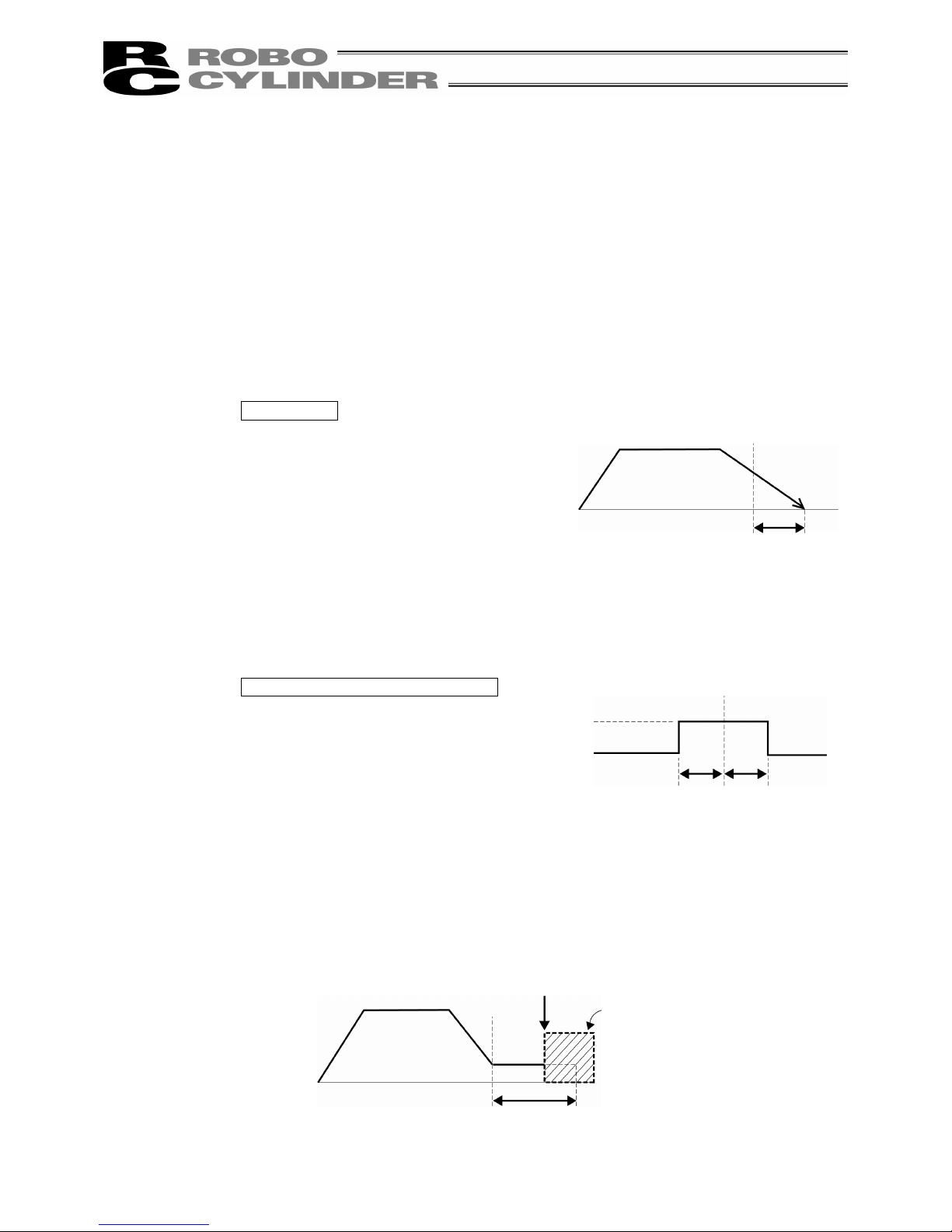
(7) Range: - The “positioning operation” and “push operation” have different meanings.
Positioning operation:
It defines the distance to the target position from a position at which the position
complete signal turns ON.
The default value is 0.1 mm.
Standard type
However, it defines the width of the position complete signal to turn ON for the 3-point type
of PCON-C/CG, ACON-C/CG and SCON and the proximity switch type of PCON-CY and
ACON-CY.
3-point type and proximity switch type
Push operation:
It defines the maximum push amount from the target position in the push
operation.
Set the positioning width in such a way as to prevent positioning completion
before the actuator contacts work by considering mechanical variations of
work.
Since increasing the positioning width value
hastens the next sequence operation, it
becomes a factor for tact time reduction.
Set the optimum value by considering the
balance of the entire equipment.
Timing of position
complete signal turning ON
Positioning width
Target
position
Positioning width
Target
position
Position complete signal
ON
Position at which the position complete
signal turns ON when the actuator contacts
Target
position
Positioning width
(Maximum push amount)
Work
Page 34
26
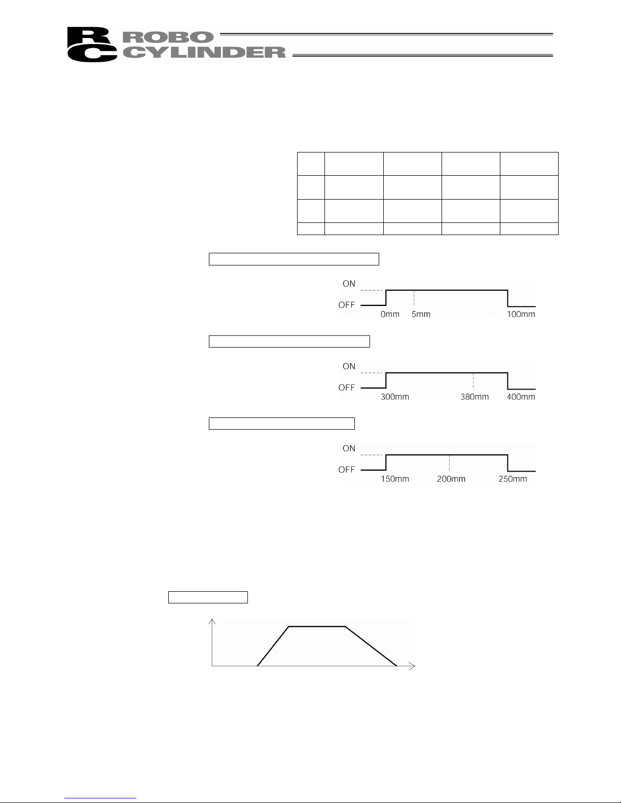
(8) Zone +/-: - It defines the zone where the zone output signal of the standard type turns
ON.
Individual setting is available for each target position to give flexibility.
No.
Position
[mm]
Zone+
[mm]
Zone-
[mm]
Comment
0 5.00 100.00 0.00
Backward
end
1 380.00 400.00 300.00
Forward
end
2 200.00 250.00 150.00 Midpoint
Movement command to backward end
Movement command to forward end
Movement command to midpoint
(9) Acc/Dcl Mode: - It defines the acceleration/deceleration characteristics.
The default value is 0.
0: Trapezoid pattern
1: S-shaped motion
2: First-order delay filter
Trapezoid pattern
* Set the acceleration and deceleration in the “Acc” and “Dcl” fields of the position
table.
[Setting example]
Home
Zone output signal
Backward
end
+ side limit
Zone output signal
Forward
end
Zone output signal
Midpoint
Speed
Acceleration
Deceleration
Time
Page 35
27
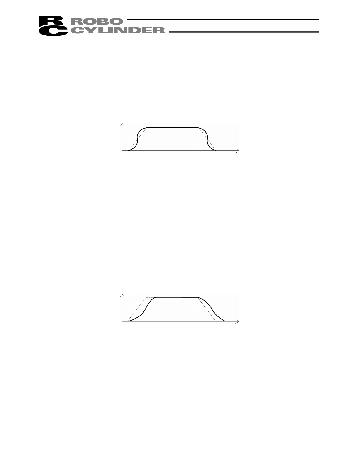
S-shaped motion
A curve, which is gradual at the beginning of acceleration but rises sharply
halfway, is drawn.
Use it in the applications for which you want to set the
acceleration/deceleration high due to tact time requirement but desire a
gradual curve at the beginning of movement or immediately before stop.
* Set the degree of the S-shaped motion with the parameter No. 56 [S-shaped
motion ratio setting]. The setting unit is % and the setting range is between 0 and
100.
(The above is the image graph when 100% setting is made.)
If “0” is set, the S-shaped motion becomes invalid.
However, it will not be reflected in jogging/increment movement by PC or
Teaching Pendant operation.
(Note) It cannot be set for the PCON controller. The parameter No. 56 is reserved.
First-order delay filter
More gradual acceleration/deceleration curves are drawn than the linear
acceleration/deceleration (trapezoid pattern).
Use this in the applications by giving micro vibrations to work during
acceleration/deceleration not desired.
* Set the degree of the first-order lag with the parameter No. 55 (constant for the
position command first-order filtering). The setting unit is 0.1 msec and the
setting range is between 0.0 and 100.0.
If “0” is set, the first-lag filter will become invalid.
However, it will not be reflected in jogging/increment movement by PC or
Teaching Pendant operation.
(Note) It cannot be set for the PCON controller. The parameter No. 55 is reserved.
(10) Cmnd Mode: - This field is invalid.
The factory setting is 0.
Speed
Time
Speed
Time
Page 36
28
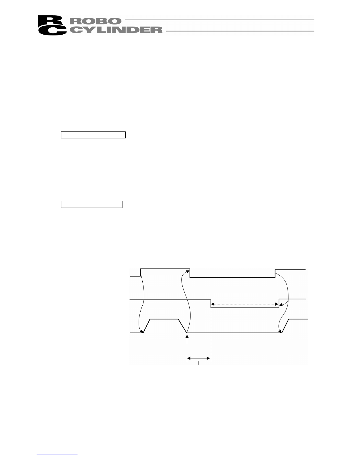
(11) Stop Mode: - It defines the power saving method on standby after completion of
positioning to the target position set in the “Position” field of the position
number.
0: Invalid power saving method * The default setting is 0 (invalid).
1: Auto servo OFF method. Delay time defined with the parameter No. 36
2: Auto servo OFF method. Delay time defined with the parameter No. 37
3: Auto servo OFF method. Delay time defined with the parameter No. 38
4: Full servo control method
Full servo control method
The holding current can be reduced by servo-controlling the pulse motor.
The degree of reduction varies depending on the actuator model, load condition, etc., but the
holding current decreases approximately by a factor of 2 to 4.
No displacement occurs since this method maintains the servo ON status.
The actual holding current can be checked on the monitoring screen of PC-compatible
software.
Auto servo OFF method
When a given length of time has elapsed after completion of positioning, the servo OFF status
is automatically entered.
(Since the holding current does not flow, the power consumption can be saved by the same
amount.)
When a movement command is subsequently given from PLC, the status returns to the servo
ON and the actuator starts to move.
Movement
command
Servo status
Actuator
movement
Servo ON status
Auto servo OFF
(Green LED flashing)
Target position
T: Delay time (sec) until the servo
OFF status is entered after
completion of positioning
It is set with the parameter.
Page 37

29
8-5-2 Position Data Table Contents for RCP, RCS, E-Con and RCP2
The setting items of the position data table are No., Position, Vel, Acc/Dcl, Push, Range and Acc
only MAX. They are displayed in 3 screens.
(1) No. Indicates the position data number.
To specify relative coordinates, move the cursor here and press the minus key. The “=”
sign will appear between No. and Position.
By pressing the minus key again, “=” disappears and the screen returns to absolute
coordinates.
(2) Position: Input the target position to move the actuator to, in [mm].
- Absolute Coordinates: Input the target location by determining the distance
between the original point and target position. No negative
value can be input.
- Relative Coordinates: Input the target location by determining the distance
between the current position and target position. Any
negative value can be input (if coordinates are in the
negative direction).
Caution:
In the case of PCON, ACON or SCON, there are cases where the input value to “Push”
may be rounded off to the multiple of the minimum resolution of the controller (during
data acquisition from the controller).
(3) Vel: Input the speed at which the actuator will be moved, in [mm/sec].
The initial value will depend on the actuator type.
(4) Acc/Dcc: Input the acceleration/deceleration at which the actuator will be moved, in [G].
The initial value will depend on the actuator type.
(5) Push: - Select the positioning operation or push operation.
The default value is “0.”
0: Normal positioning operation
Other than 0: Indicates the current-limiting value and indicates the push operation.
- In the case of push mode, data number is the servo motor current control value during
push. Uses a value that matches the actuator with a maximum value of 100%.
Page 38

30
(6) Range: - Enter the positioning completion detection width in mm (distance to the target
position) in the positioning mode.
- The distance to the target position indicates that the value input here is the upstream
distance prior to reaching the target position and the position complete signal is output
when the actuator enters that upstream range.
The default value will depend on the actuator type. (see diagram A)
- Enter the maximum push amount (distance from the target position) in the push
mode. [mm] (see diagram B)
- When the push direction is a negative direction from the displayed coordinate, a
“negative” sign should be placed in the range column.
Diagram A Diagram B
(7) Acc only MAX: - Selects either the assigned acceleration or the maximum acceleration. Inputs
are either 1 or 0. The default value is set as 0.
0: Assigned acceleration
The value placed in (4) will be used as the actual acceleration value and
deceleration value.
1: Maximum acceleration
This will automatically utilize the maximum acceleration matched to the
load.
Deceleration remains as the assigned value in (4).
Speed Speed
(5) When push = 0
(2) Distance up to the position
(5) When push = other than 0
(2) Distance up to the position
Transfer distance Transfer distance
(6) Positioning
width
(6) Positioning
width
Speed
Speed
(7) When Acc only MAX = 0
Transfer
distance
(7) When Acc only MAX = 1
Transfer
distance
The maximum acceleration
matches the load
(4) The value set in
Acc/Decl
(4) The value set in
Acc/Decl
Page 39

31
8-5-3 Data New Input
The following 4 ways to input new position data exist:
(1) Numeric Input (MDI) Numeric input the position data directly from the Teaching Pendant ten keys.
(For the input example, see page 33.)
(2) Direct Teach Turn the servo controller OFF, manually move the slider to match the
desired location and read and command that location into the position table.
(For the input example, see page 42.)
(3) Jog Use the arrow key to jog move and match the desired location and read that
location (current position) into the position table. (For the input example, see
page 45.)
If you continue pressing the arrow key, the actuator will move at a specified
speed (1, 10, 30, 50, 100 mm/sec). However, only the maximum speed will
be gained if the maximum speed is slower than the specified speed.
(4) Increment Use the arrow key to incrementally move and match the desired location
and read that location (current position) into the position table. (For the input
example, see page 47.)
If you press the arrow key once, the actuator will move by a specified pitch
(0.03, 0.10, 0.50 [mm]). If you continue pressing the arrow key, the actuator
will move by jogging at 1 mm/sec. in 2 sec. The speed will then increase
every one second. Finer movement than jogging is possible.
Examples of each operation will be explained as follows.
Caution:
When input position data is performed first after power-on or method of (2), (3), or (4),
it is required to perform home return in advance. (Increment specification)
:
Jog and Increment movement prior to homing incomplete status is possible up to the
slider end. Visually, perform the interference check.
Page 40
32
1) Homing
Perform temporary stop reset and servo ON input in advance.
Alternatively, disable servo ON input and temporary stop reset with User Adjustment.
(There is no servo ON input for RCP.)
Caution:
Operating instructions are described on the screens of PCON, ACON and SCON.
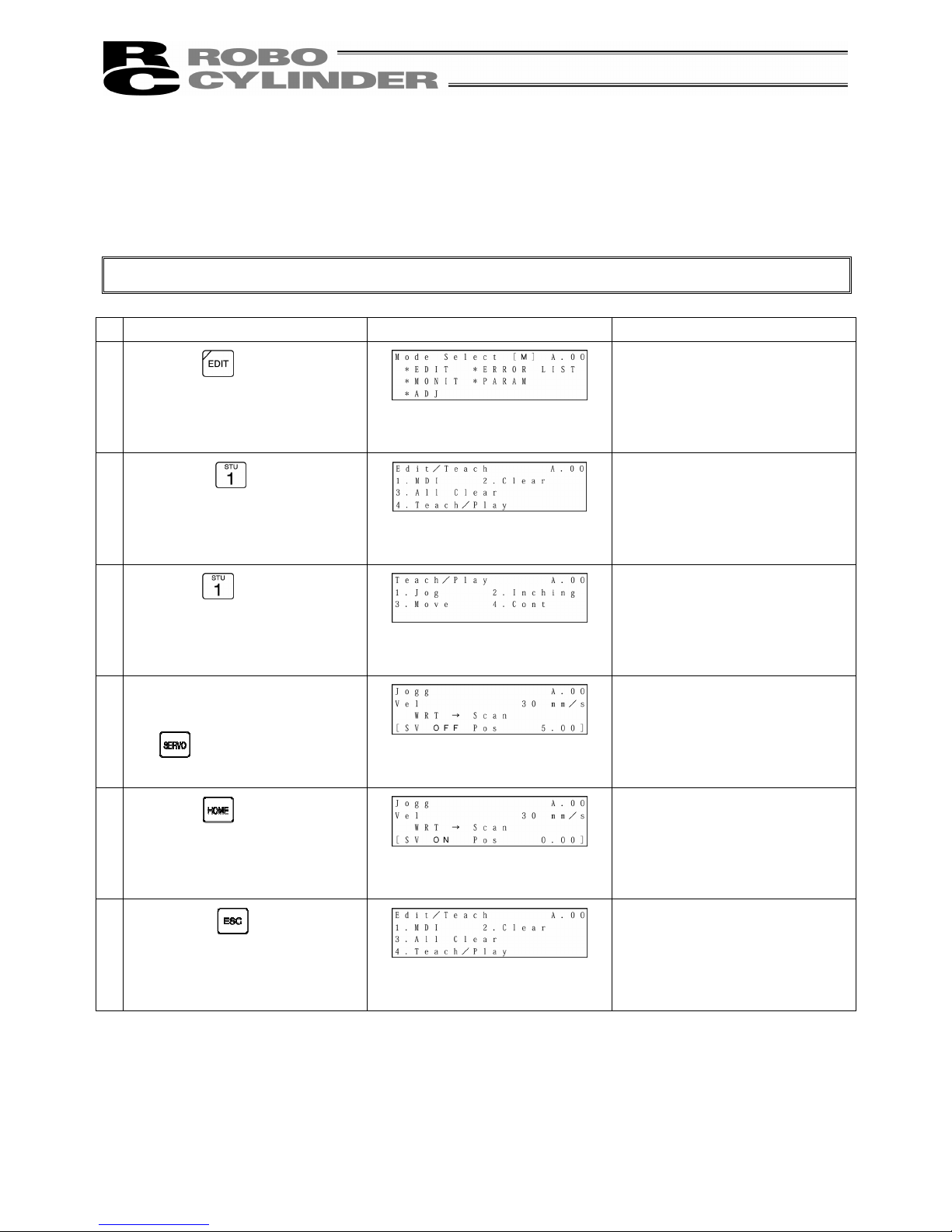
Operation Screen Reference
1.
Press the
key.
2.
Press the
key to select
“MDI.”
3.
Press the
key to select Jog.
4.
If the SV OFF (servo OFF) status
is displayed on the screen, press
the
key.
The servo will automatically be
turned ON.
“SV ON” (servo ON) will be
displayed on the screen.
5.
Press the key.
Homing will automatically be
performed.
6.
Press the key twice to
return to the Edit/Teach screen,
Page 41
33
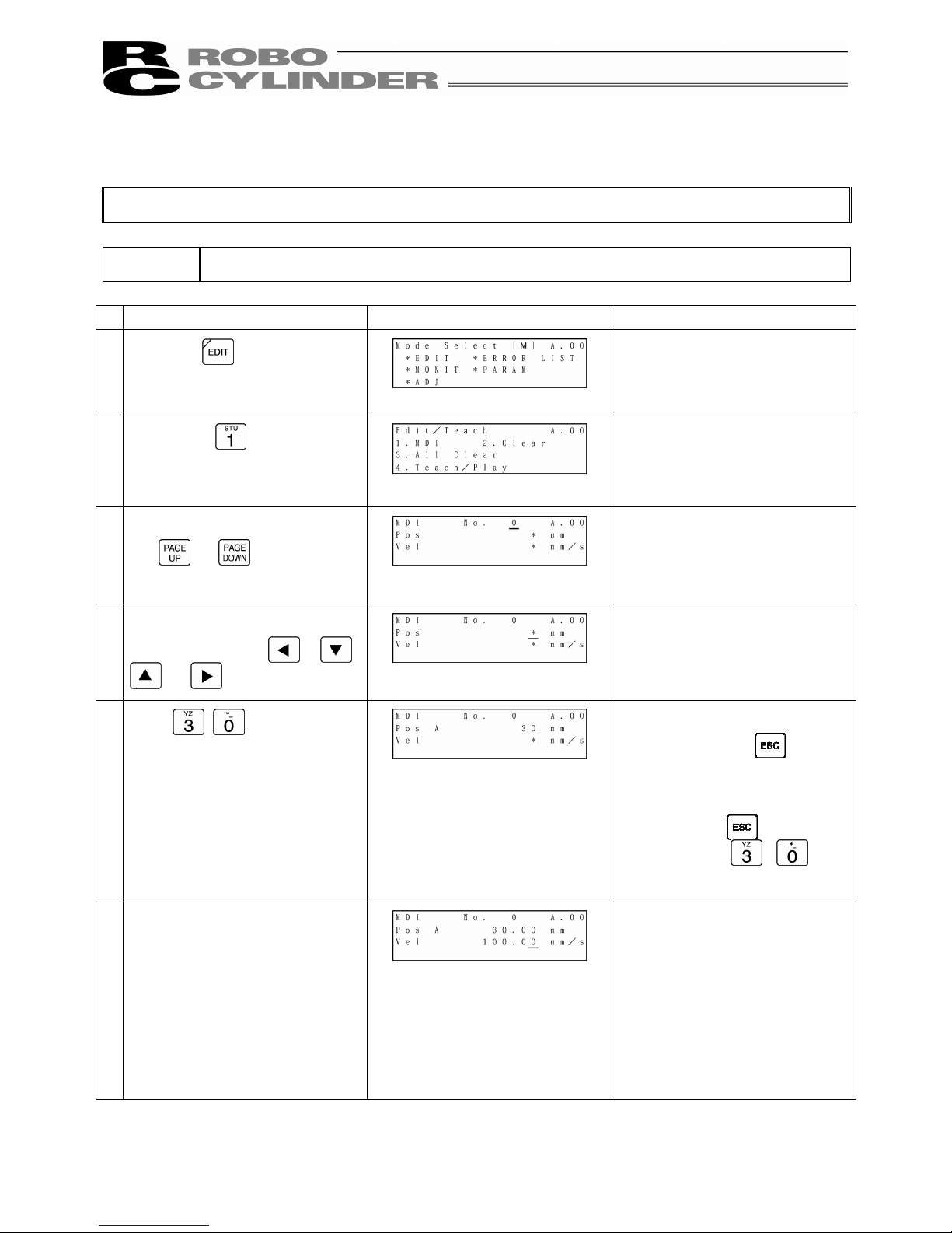
2) Numeric Input
Caution:
Operating instructions are described on the screens of PCON and ACON, SCON.
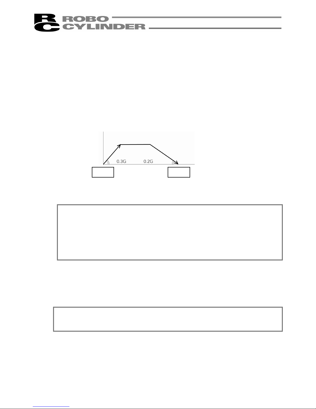
Example 1: 2 point continuous loop move 30mm <-> 250mm, Speed 300mm/sec
Operation Screen Reference
1.
Press the
key.
2.
Press the
key to select
“MDI.”
3.
Set 0 into the position No. with
the
or key.
For any unregistered data, the
display will show “*” sign.
4.
Move the cursor to the “Pos” input
position with the
, ,
or key.
5.
Input
here, and then
press the Return key.
In order to stop during numeric
input, press the
key to
cancel the input.
Example) With the left operation,
by pressing
immediately
after inputting
, the
status will return to the “*” display.
6.
During new position data
registration, the initial values set
with the user parameters for Vel,
Acc, Dcc, etc., will automatically
be input.
In the left screen, the initial value
is set as 100 mm/sec.
Page 42

34
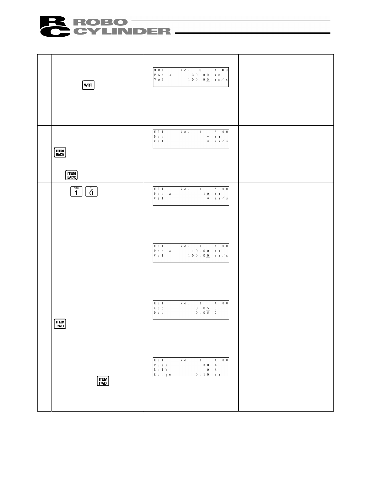
Operation Screen Reference
7.
Input
here, and
then press the Return key.
Press the key.
(The cursor will automatically
move to the next [No. 1].)
The screen will change to the
screen of Position No. 1 for Acc
and Dcc.
8.
Change the screen to the screen
for Pos and Vel with the
key.
Move the cursor to “Pos” with the
key.
9.
Move the cursor to the “Pos”
input position with the
,
, or key.
Input
here, and
then press the Return key.
In order to stop during numeric
input, press the key to
cancel the input.
10.
The cursor will automatically
move to the “Vel” input position.
Page 43

35
Operation Screen Reference
11.
Input
here, and
then press the Return key.
Press the key.
(The cursor will automatically
move to the next [No. 2]
position.)
The screen will change to the
screen of Position No. 2 for Acc
and Dcc.
Page 44

36
Example 2:
2 point continuous loop move Push operation 10mm position <-> 80mm position
(Push range 5mm)
Operation Screen Reference
1.
Press the
key.
2.
Press the
key to select
“MDI.”
3.
Set 0 into the position No. with
the
or key.
For any unregistered data, the
display will show “*” sign.
4.
Move the cursor to the “Pos” input
position with the
, ,
or key.
5.
Input
here, and then
press the Return key.
In order to stop during numeric
input, press the key to
cancel the input.
Example) With the left operation,
by pressing
immediately
after inputting
, the
status will return to the “*” display.
6.
During new position data
registration, the initial values set
with the user parameters for Vel,
Acc, Dcc, etc., will automatically
be input.
In the left screen, the initial value
is set as 100 mm/sec.
Page 45

37
Operation Screen Reference
7.
Press the Return key.
Press the
key.
(The cursor will automatically
move to the next [No. 1]
position.)
At the left, the user parameter is
used as it is.
The screen will change to the
screen of Position No. 1 for Acc
and Dcc.
8.
Change the display to the
screen for Pos and Vel with the
key.
Move the cursor to “Pos” with
the
key.
9.
Input
here, and then
press the Return key.
10.
The cursor will automatically
move to “Vel.”
11.
Change the display to the
screen for Acc and Dcc with the
key.
The screen will change.
12.
Change the display to the
screen for Push, LoTh and
Range with the
key.
The screen will change.
Page 46

38
Operation Screen Reference
13.
Input the current value during
push.
In this example, input 30%.
Input
and then press
the Return key.
Press the Return key again to
move the cursor to “Range.”
* For push control, refer to the
Controller Operating Manual.
14.
Input the maximum push range
during push into the Range.
In this example, input 5 mm.
Input
and then press the
Return key.
Press the
key.
The screen will change to the
screen of Position No. 2 for Push,
LoTh and Range.
Page 47

39
Example 3: Relative Coordinates pitch movement 30 mm → 40 mm → 50 mm….
Operation Screen Reference
1.
Press the
key.
2.
Press the
key to select
“MDI.”
3.
Set 0 into the position No. with
the or key.
For any unregistered data, the
display will show “*” sign.
4.
Move the cursor to the “Pos” input
position with the
, ,
or key.
5.
Input
here, and then
press the Return key.
In order to stop during numeric
input, press the
key to
cancel the input.
Example) With the left operation,
by pressing
immediately
after inputting
, the
status will return to the “*” display.
6.
During new position data
registration, the initial values set
with the user parameters for Vel,
Acc, Dcc, etc., will automatically
be input.
In the left screen, the initial value
is set as 100 mm/sec.
Page 48
40
Operation Screen Reference
7.
Press the Return key.
Press the
key.
(The cursor will automatically
move to the next [No. 1]
position.)
At the left, the user parameter is
used as it is.
The screen will change to the
screen of Position No. 1 for Acc
and Dcc.
8.
Change the display to the
screen for Pos and Vel with the
key.
Move the cursor to “Pos” with
the
key.
9.
Input
here, and then
press the Return key.
10.
The cursor will automatically
move to “Vel.”
11.
Change the display to the
screen for Acc and Dcc with the
key.
The screen will change.
12.
Change the display to the
screen for Push, LoTh and
Range with the
key.
The screen will change.
Page 49
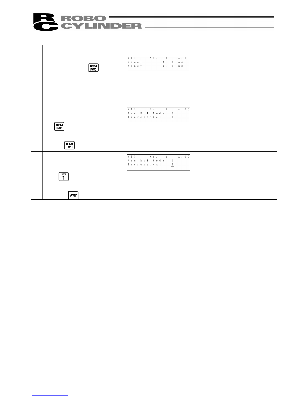
41
Operation Screen Reference
13.
Change to the screen for Zone +
and Zone- with the
key.
The screen will change.
14.
Change to the screen for Acc
Dcl Mode and Incremental with
the
key.
Move the cursor to “Incremental”
with the
key.
15.
Set to “Incremental” (relative
coordinate specification).
Input
and then press the
Return key.
Press the key.
The screen will change to the
screen of Postion No. 2 for Cmnd
Mode and Stop Mode.
Page 50
42
3) Direct Teach
(Method: Manually moving the actuator, matching to the desired position and teaching that position into the
position table)
When direct teach operation is performed first after power-on, it is required to perform home return operation
in advance. (Refer to page 32.) (Increment specification)
Caution:
Operating instructions are described on the screens of PCON, ACON and SCON.
Example: 2 point continuous loop Point A --> Point B, speed 300mm/sec
Operation Screen Reference
1.
Press the
key.
2.
Press the
key to select
“Teach/Play.”
3.
Press the
key to select
“Jog.”
(Note) Even if “2. Inching” is
selected, the same direct
teaching will be available.
4.
Press the
key.
5.
Set the position No. you want to
input with the
and
key.
Press the key to put into
the servo OFF status.
Any remaining data will be written
over.
For any unregistered data, the
display will show “*” sign.
Page 51

43
Operation Screen Reference
6.
Manually move the slider and
match to the desired position.
Press the Return key.
The controller status will be
displayed on the bottom row of
the screen.
Servo Control: OFF
Position: 100.00
You can change the position No.
you want to input with the
and key.
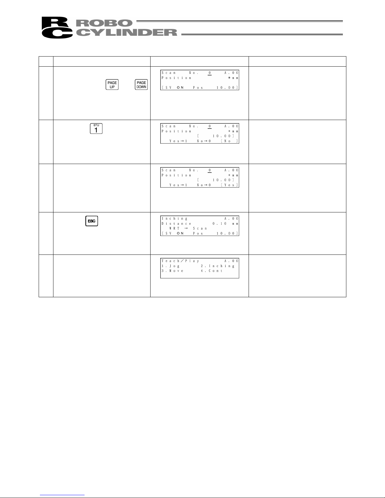
7.
Press the
key to select
“Yes.”
8.
Press the Return key.
As for Vel, Acc, Dcc, etc., the
initial value set with the user
parameter will automatically be
input.
(Note) If scan is performed
without executing homing, the
error message “Homing
Incomplete” will be displayed.
Return to the screen of 6 above
with the ESC key to put into the
servo ON status and press the
key to execute homing.
9.
Press the
key.
10.
Page 52
44
Operation Screen Reference
11.
Set the position No. youu want to
input with the or
key.
12.
Manually move the slider and
match to the desired position.
Press the Return key.
13.
Press the
key to select
“Yes.”
14.
Press the Return key.
15.
Press the key.
16.
The screen will return to the
Teach/Play select screen.
Page 53

45
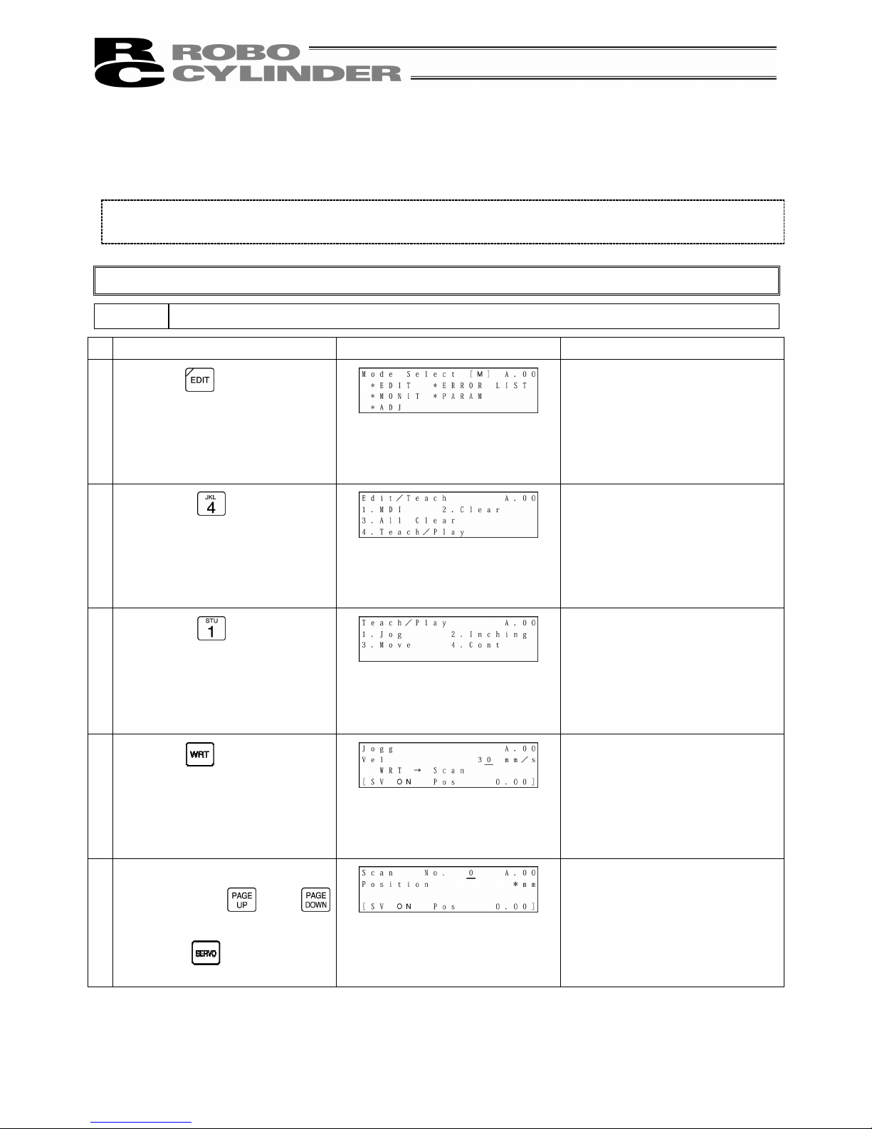
4) Jog Teach
(Method: Tagging the actuator, matching to the desired position and teaching that position into the position
table)
However, only the maximum speed will be gained if the maximum speed is slower than the specified speed.
When jog operation is performed first after power-on, it is required to perform home return operation in
advance. (Refer to page 32.) (Increment specification)
Caution:
Operating instructions are described on the screens of PCON, ACON and SCON.
Example: 2 point continuous loop Point A --> Point B, speed 300mm/sec
Operation Screen Reference
1.
Press the
key.
2.
Press the
key to select
“Teach/Play.”
3.
Press the
key to select
“Jog.”
4.
Input the desired jog speed with
the ten keys and press the Return
key.
The input range is from 1 mm/sec
to the safety speed set for the
parameter.
5.
Move the slider with the
or
key and match to the
desired position.
6.
Press the
key.
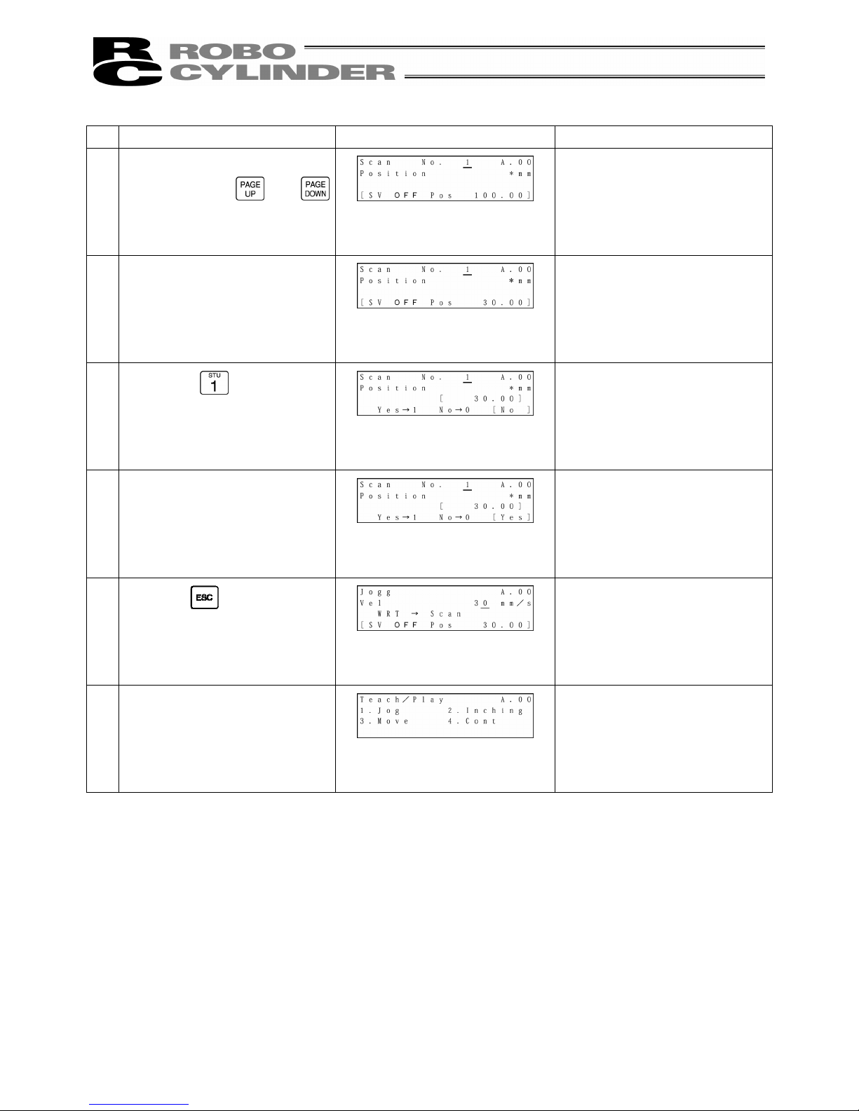
Page 54

46
Operation Screen Reference
7.
Set the position No. you want to
input with the or key.
Press the Return key.
Any remaining data will be
written over.
For any unregistered data, the
display will show “*” sign.
8.
Press the
key to select
“Yes.”
9.
Press the Return key.
As for Vel, Acc, Dcc, etc., the
initial value set with the user
parameter will automatically be
input.
10.
Press the key.
11.
The screen will return to the
Teach/Play select screen.
Page 55
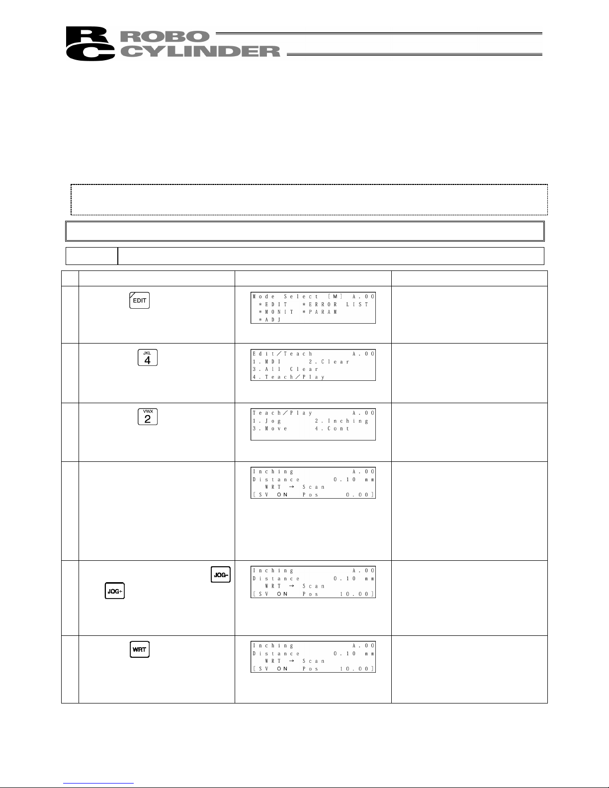
47
5) Inching
(Method: Incremental movement using arrow key, matching to the desired position and teaching that
position into the position table)
If you press the JOG- and JOG+ key once, the actuator will move by a specified pitch.
If you continue pressing the arrow key, the actuator will move by jogging at 1 mm/sec. The speed will
increase every one second. Finer movement than jogging is possible.
When inching movement is performed first after power-on, it is required to perform home return operation in
advance. (Refer to page 32.) (Increment specification)
Caution:
Operating instructions are described on the screens of PCON, ACON and SCON.
Example: 2 point continuous loop Point A --> Point B, speed 300mm/sec
Operation Screen Reference
1.
Press the
key.
2.
Press the
key to select
“Teach/Play.”
3.
Press the
key to select
“Inching.”
4.
Input the desired inching distance
with the ten keys and press the
Return key.
The input range is from 0.01 mm
to 1.00 mm.
5.
Move the slider with the
and
key and match to the
desired position.
6.
Press the
key.
Page 56
48
Operation Screen Reference
7.
Set the position No. you want to
input with the or
key.
Press the Return key.
Any remaining data will be
written over.
For any unregistered data, the
display will show “*” sign.
8.
Press the
key to select
“Yes.”
9.
Press the Return key.
As for Vel, Acc, Dcc, etc., the
initial value set with the user
parameter will automatically be
input.
10.
Press the key.
11.
The screen will return to the
Teach/Play select screen.
Page 57

49
8-5-4 Data Modification
You may write over all of the position data.
Similar to new input, the following 4 cases exist:
(1) Numeric Input (MDI): Manually enter the position data directly from Teaching Pendant ten keys.
(2) Direct Teach: Turns the servo OFF, manually move the slider to the desired location and
read that location (current position) into the position table.
(3) Jog: Use the arrow keys to jog to the desired location and read that location
(current position) into the position table.
(4) Increment: Use the arrow keys to incrementally move and read that location (current
position) into the position table.
Caution during data modification:
* As for manual input, the data entered will erase the old data.
* The position will be updated only when the Return key is pressed to read in the current location (direct
teach, jog, increment). It does not influence speed and others.
* Once the position data is cleared, the previous data will no longer remain anywhere. Therefore, when
the next position data is registered, any data other than position will be default values.
When clearing to re-set the push assign position data, be sure to confirm all items of the position data to
input required data.
8-5-5 Clear • All Clear
In this section, we will give specific examples of how to clear data in the position table.
(1) Clear: Resets the assigned position data. The data will become unregistered. (For the
input example, see page 50.)
(2) All Clear: Resets all of all position data. (For the input example, see page 51.)
Page 58

50
1) Clear
(Method: To clear the position data of assigned location)
Caution:
Operating instructions are described on the screens of PCON, ACON and SCON.
Example: Clear the row of position data number 2.
Operation Screen Reference
1.
Press the
key.
2.
Press the
key to select
“Clear.”
3.
Set the position No. you want to
clear with the or key.
Press the Return key.
4.
Press the
key to select
“Yes.”
5.
Press the Return key.
6.
The data of the specified position
No. will be cleared.
Page 59
51
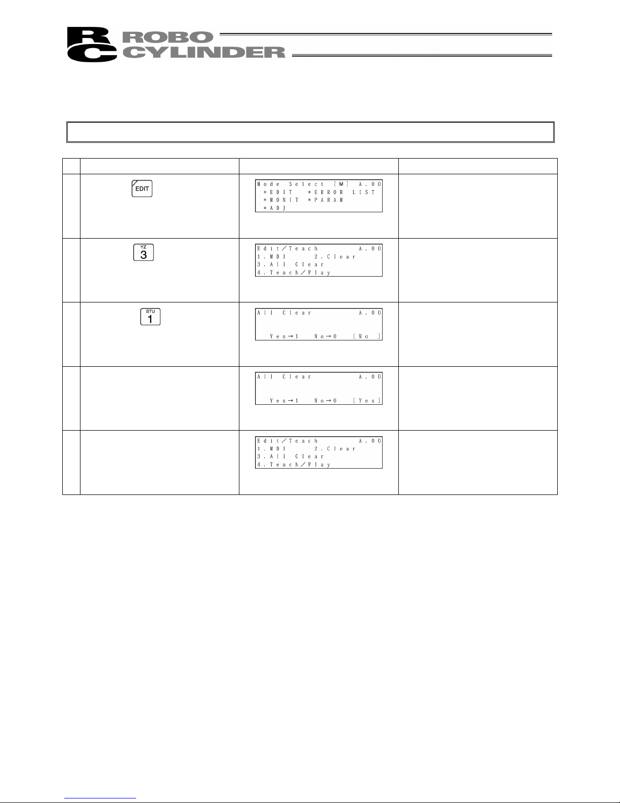
2) All Clear (Operation: To clear all position data)
Caution:
Operating instructions are described on the screens of PCON, ACON and SCON.
Operation Screen Reference
1.
Press the
key.
2.
Press the
key to select “All
Clear.”
3.
Press the
key to select
“Yes.”
4.
Press the Return key.
5.
All position data will be cleared.
Page 60

52
8-5-6 Move
You may move towards a position registered in the position data table (1 step move) and
continuously move through the continuous position data.
In this section, the move will differ from jog and increment move used with the arrow key. This will
be moved towards a position that was registered in the position data table within the controller.
Use this move for test operation etc.
(1) Move 1 step move from the current location to the assigned position number registered in the
position table.
(2) Continuous Continuous operation from the assigned position data number to the continuous position
data number until an empty location is reached.
* What is Continuous?
In the case of the position data similar to the table below, when a Continuous command is
executed from the position No., the place where data exists continuously (to the position
before unregistered data (*)) will operate as one group (Example: Position No.2 Æ No. 3 Æ
No. 1 Æ No.2 and so on).
Posi. Vel. Acc./Dcc.
In the case of the Teaching Pendant, continuous movement is performed only through 64
positions such as position No. 0-63 and No. 64-127.
As shown in the example below, continuous movement continues by returning to position No.
61 after No. 63 (returning to the first position No. where position data is continuously input).
No movement is made from position No. 63 to No. 64.
Position Velocity
Page 61

53
Specific examples will be provided to explain operation procedures.
Caution:
With regard to PCON, ACON and SCON, complete positions will be output.
The positioning complete output will not turn ON when push mode does not encounter a force.
When move or Continuous is performed first after power-on, it is required to perform home
return operation in advance. (Refer to page 32.) (Increment specification)
1) Move
(Operation: Registered position data number assigned move)
Caution:
Operating instructions are described on the screens of PCON, ACON and SCON.
Example: Current position → move towards position number 2, 3
Operation Screen Reference
1.
Press the
key.
2.
Pres the
key to select
“Teach/Play.”
3.
Press the
key to select
“Move.”
4.
For any unregistered data, the
display will show “*” sign.
5.
Set the position No. you want to
move with the
or key.
Press the Return key.
Page 62

54
Operation Screen Reference
6.
Select “Vel” with the
or
key.
Speed is divided into 3 levels and
can be selected using the
or key.
With the
key, the speed will
change in the incremental
direction (10%→50%→100%).
With the
key, the speed will
change in the decremental
direction (100%→50%→10%).
(Note) When PCON, ACON or
SCON is connected, the
maximum speed will be the
safety speed set for the
parameter if the MANU operation
mode is set to the Teach mode 1
(safety speed: valid).
7.
If you press the
key,
movement will be made to the
location of the position No. you
set.
When the servo is not ON, press
the
key to put into the
servo ON status.
8.
When moving towards position of
No. 3 continuously:
Set 3 into the position No. with
the
key.
If you press the
key
continuously, movement will be
made to the location of position
No. 3.
Page 63
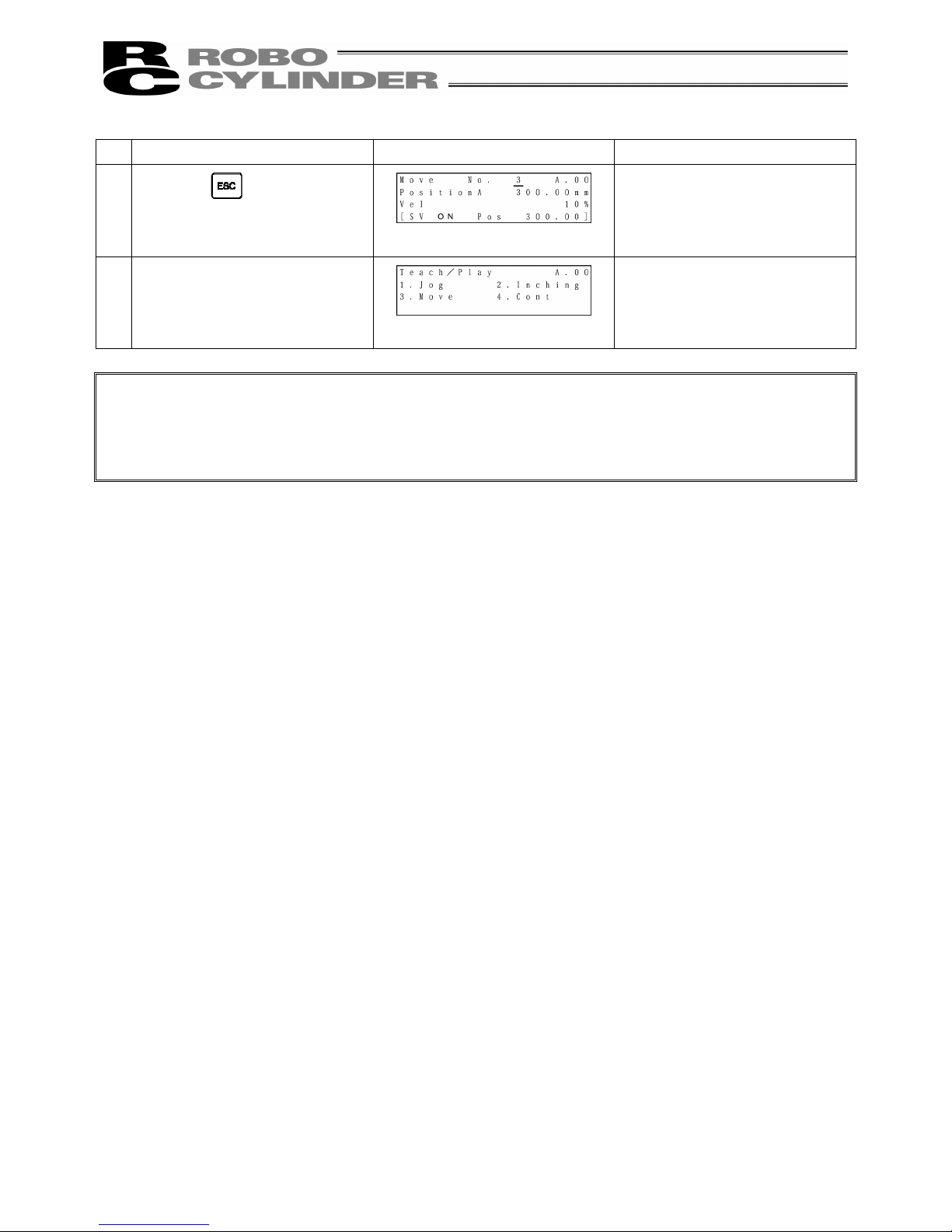
55
Operation Screen Reference
9.
Press the key.
10.
The screen will return to the
Teach/Play select screen.
Caution:
When moving towards position in push mode.
After the actuator pushes the work and position complete output turns ON, the actuator is in a state
of continuously pressing the work.
Be extremely careful about handling at this time.
Page 64
56
2) Continuous Move
(Operation: Registered position data number assigned continuous move)
Caution:
Operating instructions are described on the screens of PCON, ACON and SCON.
Example: Current position → Continuous move towards position numbers 1 to 3
Operation Screen Reference
1.
Press the
key.
2.
Press the
key to select
“Teach/Play.”
3.
Press the
key to select
“Cont.”
4.
For any unregistered data, the
display will show “*” sign.
5.
Set the position No. you want to
move first with the
or
key.
Press the Return key.
Page 65

57
Operation Screen Reference
6.
Select “Vel” with the
or
key.
Speed is divided into 3 levels and
can be selected using the
or key.
With the
key, the speed will
change in the incremental
direction (10%→50%→100%).
With the
key, the speed will
change in the decremental
direction (100%→50%→10%).
(Note) When PCON, ACON or
SCON is connected, the
maximum speed will be the
safety speed set for the
parameter if the MANU operation
mode is set to the Teach mode 1
(safety speed: effective).
7.
If you press the
key,
continuous movement will start.
The screen display will change to
the screen of the position No.
currently moving.
When the servo is not ON, press
the
key to put into the
servo ON status.
8.
When stopping continuous
operation, press the
or
key.
When the key is pressed,
operation will decelerate and
stop.
When performing continuous
operation again, press the
key.
Page 66

58
Operation Screen Reference
9.
When operation stops, press the
key.)
10.
The screen will return to the
Teach/Play select screen.
Page 67
59
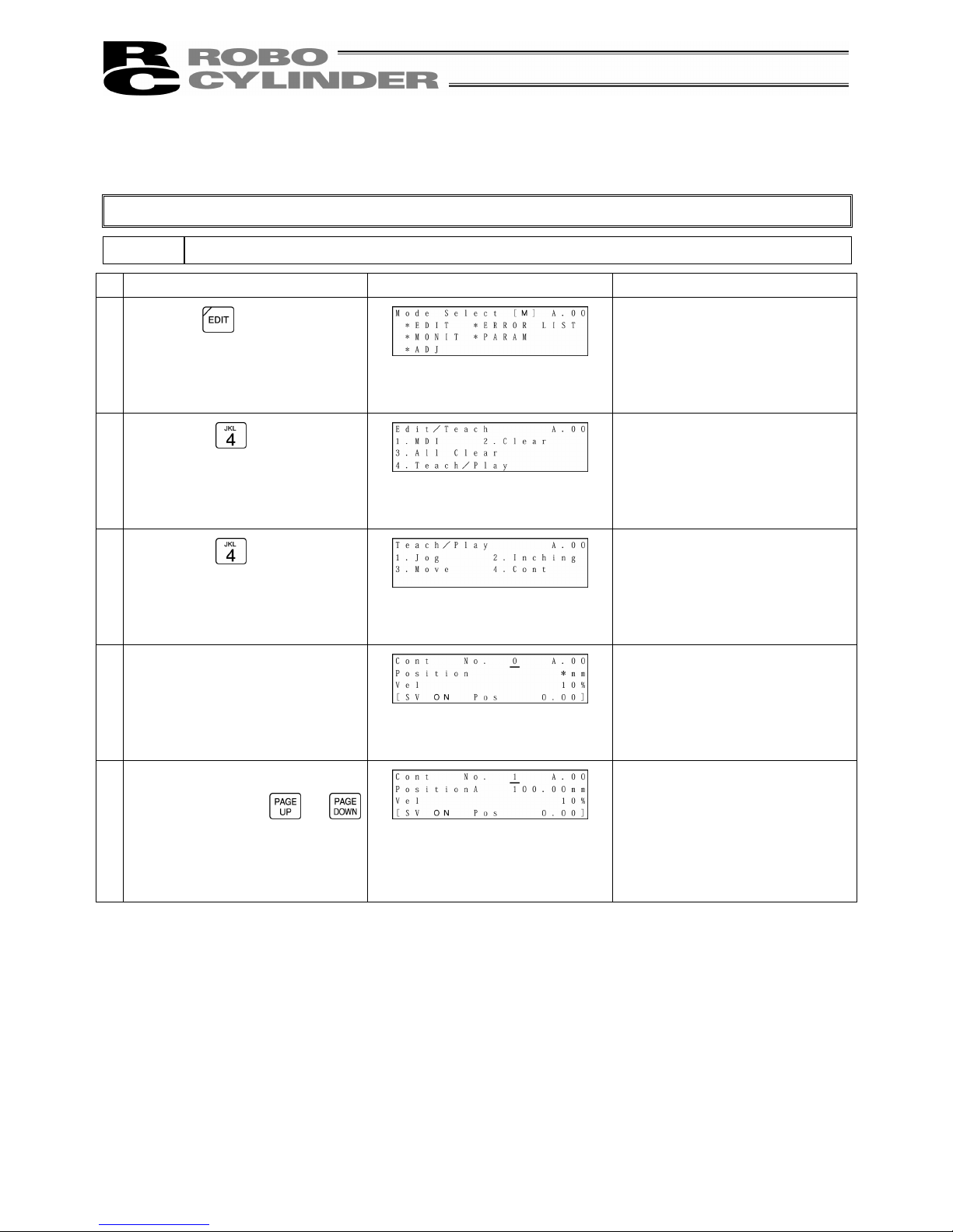
8-5-7 Servo ON/OFF
Servo ON/OFF can be performed.
Caution:
Operating instructions are described on the screens of PCON, ACON and SCON.
Operation Screen Reference
1.
Press the
key.
2.
Press the
key to select
“Teach/Play.”
3.
Press the
key to select
“Cont.”
4.
For any unregistered data, the
display will show “*” sign.
5.
If you press the key in the
servo ON status, the status will
change to the servo OFF.
6.
If you press the key in the
servo OFF status, the status will
change to the servo ON.
Servo ON/OFF can also be performed in the same way in “1. Jog,” “2. Inching,” or “4. Cont” mode.
Page 68
60
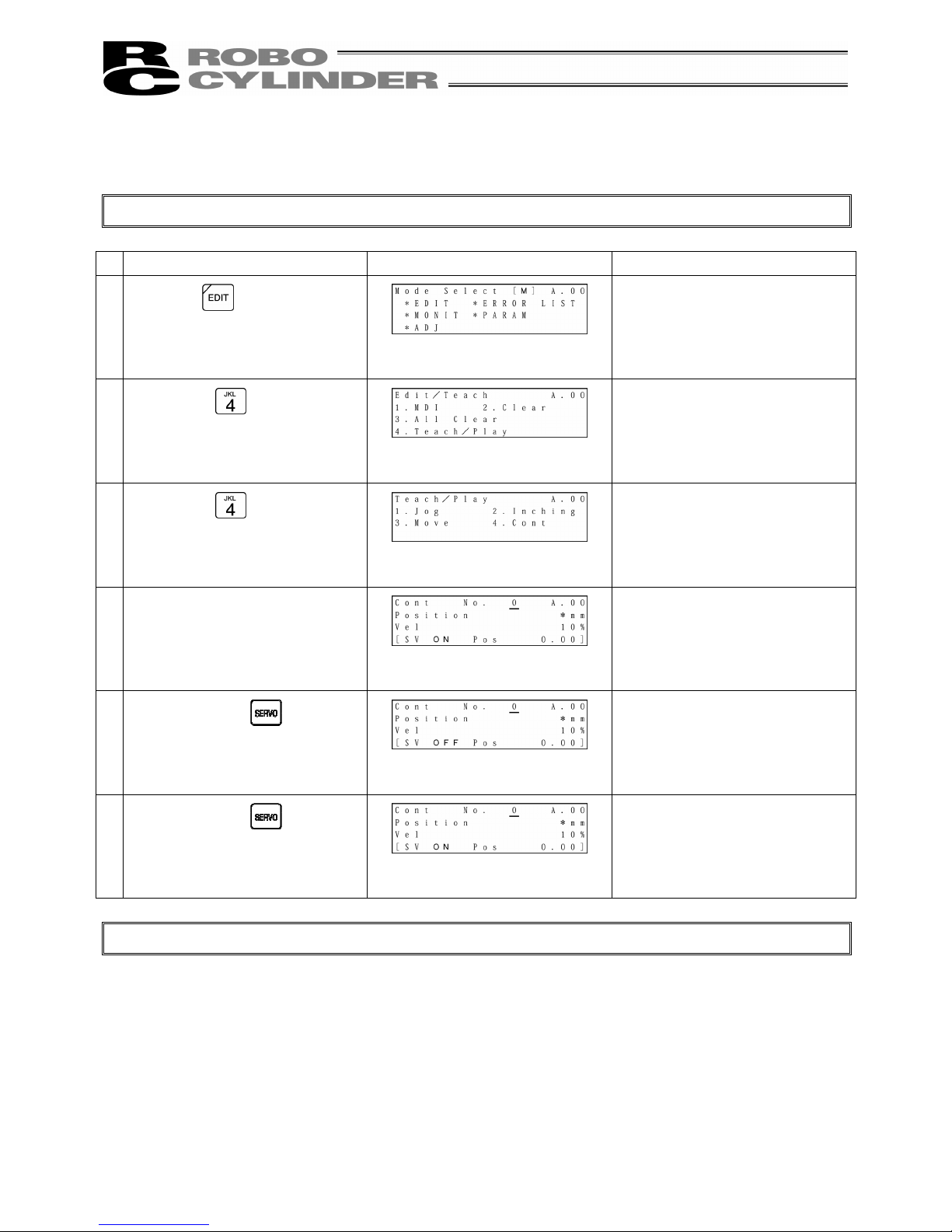
8-5-8 Pulse Train (PCON-PL/PO, ACON-PL/PO, SCON: Pulse Train Mode)
Based Jogging
In the case of the PCON-PL/PO, ACON-PL/PO, or SCON controller (pulse train mode), if you select
“Jog” on the Jog/Inching select screen, servo ON/OFF, homing, or jog operation can be performed. If
you select “Inching,” inching operation can be performed.
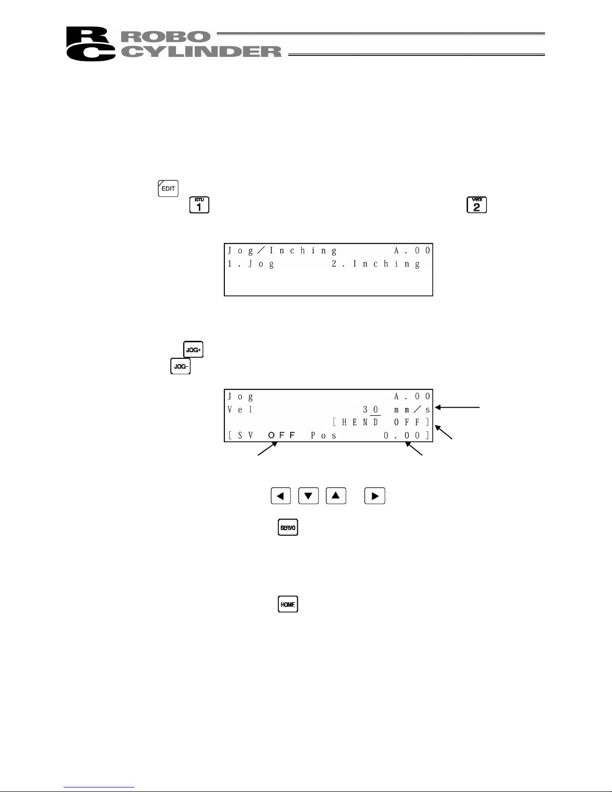
Press the
key.
If you press the
key, jog operation can be performed. If you press the key, inching
operation can be performed.
(1) Jog operation
The Jog screen will be displayed.
If you press the key, the cursor will move in the positive direction of the displayed coordinates.
If you press the
key, the cursor will move in the negative direction of the displayed coordinates.
①
Current position: Indicates the current position. The unit can be changed between mm and
pulse with the
, , or key.
②
Servo ON/OFF: If you press the
key, the servo ON/OFF status will be reversed.
③
Jog speed: Input the desired jog speed with the ten keys and press the Return key. The
input range is from 1 mm/sec to the safety speed set for the parameter.
④
Homing: If you press the
key, homing will be performed.
① Current position
④ Homing
② Servo ON/OFF
③ Jog speed
Page 69
61
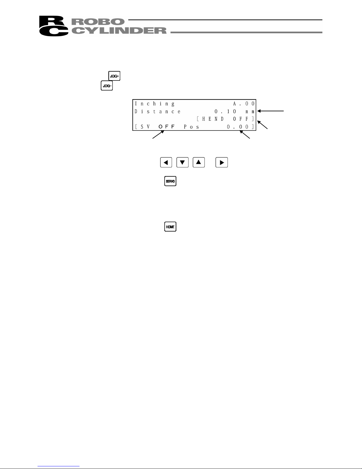
(2) Inching operation
The Inching screen will be displayed.
If you press the
key, the cursor will move in the positive direction of the displayed coordinates.
If you press the
key, the cursor will move in the negative direction of the displayed coordinates.
①
Current position: Indicates the current position. The unit can be changed between mm and
pulse with the
, , or key.
②
Servo ON/OFF: If you press the
key, the servo ON/OFF status will be reversed.
③
Inching distance: Input the desired inching distance with the ten keys and press the Return key.
The input range is from 0.01mm to 1.00mm set for the parameter.
④
Homing: If you press the
key, homing will be performed.
① Current position
④ Homing
② Servo ON/OFF
③ Inching
distance
Page 70
62
8-6 Monitor
The I/O status and current position will be displayed for all the controllers connected on the serial
communication line.
Press the
key.
After this, the screen will change to the special
input port or version display screen.
The figure at the left shows an example of the
PCON-CY controller.
* The display contents vary depending on the
controller or controller’s I/O pattern. For details,
refer to the operating manual of each controller.
If you press the or key, the axis to
monitor can be changed.
If you press the
or key, the screen will
change.
To end monitoring, press the
key.
Page 71

63
①
On the axis status screen, if you press the key, the screen will change to the input port
monitor screen.
If you press the
key, the screen will change to the version display screen.
②
On the input port screen, if you press the
key, the screen will change to the output port
monitor screen,
If you press the
key, the screen will change to the axis status screen.
③
On the output port screen, if you press the
key, the screen will change to the input port
monitor screen.
If you press the
key, the screen will change to the special input port monitor screen.
Page 72
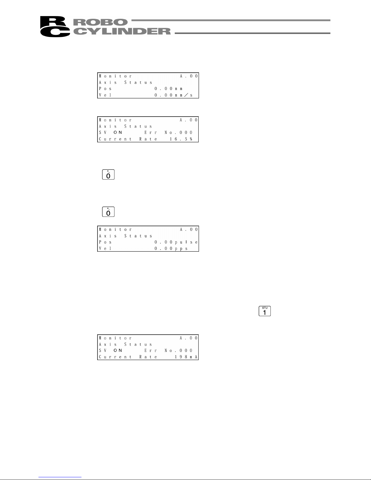
64
●
Display description
① Displays the axis position in [mm].
In the case of the PCON-PL/PO, ACON-PL/PO or SCON controller (pulse train mode), if you
press the
key, the display will change to the pulse display.
② Displays the speed of the moving axis in [mm/sec].
In the case of the PCON-PL/PO, ACON-PL/PO or SCON controller (pulse train mode), if you
press the key, the display will change to the pps display.
③
Displays the servo ON/OFF status of the axis.
④
Displays the error No. when an error occurs.
⑤
Displays the percent rated current in [%].
In the case of the PCON, ACON or SCON controller, if you press the
key, the current value
will be displayed in [mA].
①
②
③
⑤
④
Page 73

65
If you press the
key on the last screen of input ports, the special input port screen will be
displayed.
The special input port screen will display special input ports such as HMCK (home check sensor).
After this, the screen will change to the special
input port or version display screen.
If you press the
or key, the axis to
monitor can be changed.
If you press the
or key, the screen will
change.
To end monitoring, press the
key.
Page 74

66
①
On the special input port monitor screen, if you press the key, the screen will change to the
output port monitor screen.
If you press the
key, the screen will change to the version display screen.
If you press the
key on the last screen of special input ports, the version display screen will be
displayed.
If you press the
or key, the axis to
monitor can be changed.
To end monitoring, press the
key.
Page 75
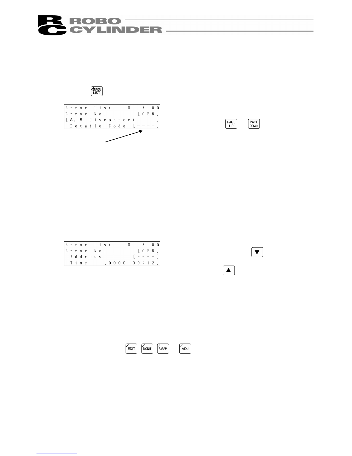
67
8-7 Error List
Errors occurring after the connection of the Teaching Pendant and those occurring after a
controller’s power-on will be displayed.
Press the
key.
The Error List screens of PCON, ACON or SCON are comprised of 0 to 16.
The previous 16 alarm-level errors including the last (latest) error will be displayed.
In the case of PCON, ACON or SCON, the alarm list contents will be maintained even after the
power is turned OFF.
The Error List screens of RCP2, RCS, E-Con or RCP2 are comprised of 0 to 8.
The previous 8 alarm-level errors including the last (latest) error and one last-detected error of the
warning level will be displayed.
(Note) The power ON log (no error) displays that the power has been applied to the controller. No
error has occurred.
Time displays the time elapsed from this power ON log (no error).
If you press one of the
, , or keys, the mode will change to the mode of the
pressed key.
Errors occurring in the controller will be displayed.
If you press the
or key, the Error List
screens can be changed.
Alarm detailed code
(In the case of “0,” - - - - will be displayed.)
On the screen where the error description is
displayed, if you press the
key, Address and
Time will be displayed.
If you press the
key, the screen will return to
the previous screen.
Page 76

68
8-8 User Parameters
8.8.1 User Parameters
Parameters are displayed and edited.
Press the
key.
Each parameter can be changed using the
or
key.
When the cursor is located at “No.,” it is also
possible to change to the desired user parameter by
directly inputting a numeric value of the parameter
No. with the ten key and pressing the Return key.
When changing a parameter, move the cursor to the
parameter value with the
, , or
key or Return key.
Input a numeric value with the ten key and press the
Return key.
Press the key.
The screen will change to the next screen. Press the
key.
When “1” (Yes) is selected for “Is the writing data
written?,” the screen will change to the Software
Reset screen.
Press the
key and press the Return key.
Page 77

69
Models which support the software reset (restart) are PCON, ACON and SCON.
For any model which does not support the software reset, restore the power to the controller.
On the following page, user parameter display examples of the PCON-CY controller are provided.
* The contents will vary depending on each controller. Refer to the operating manual of each
controller.
When the servo is ON, the screen will change to the
Servo OFF confirmation screen.
If you press the
key and then press the Return
key, the controller will restart and the screen will
change to the Mode Select screen. Since servo is
automatically turned OFF, it is not required to turn
SON input OFF.
Page 78

70
Examples of PCON-CY Controller
On following page
Page 79

71
From previous page
On following page
Page 80
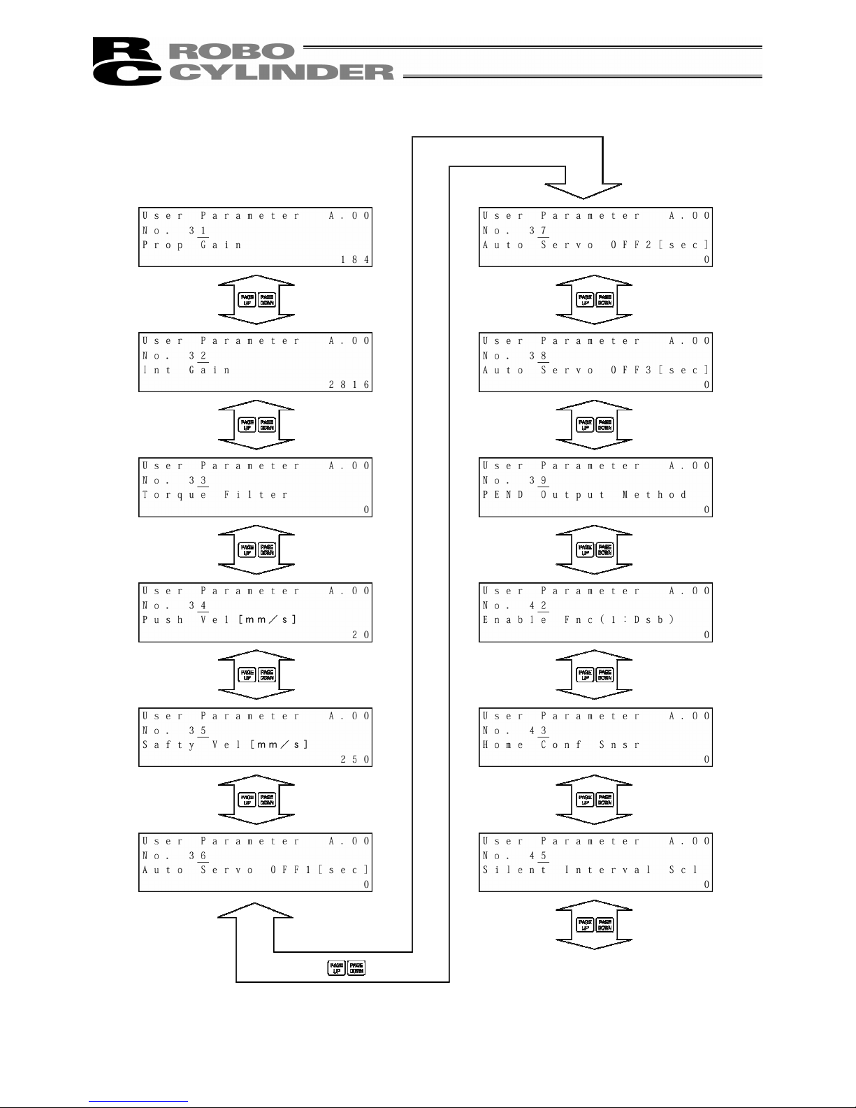
72
From previous page
On following page
Page 81
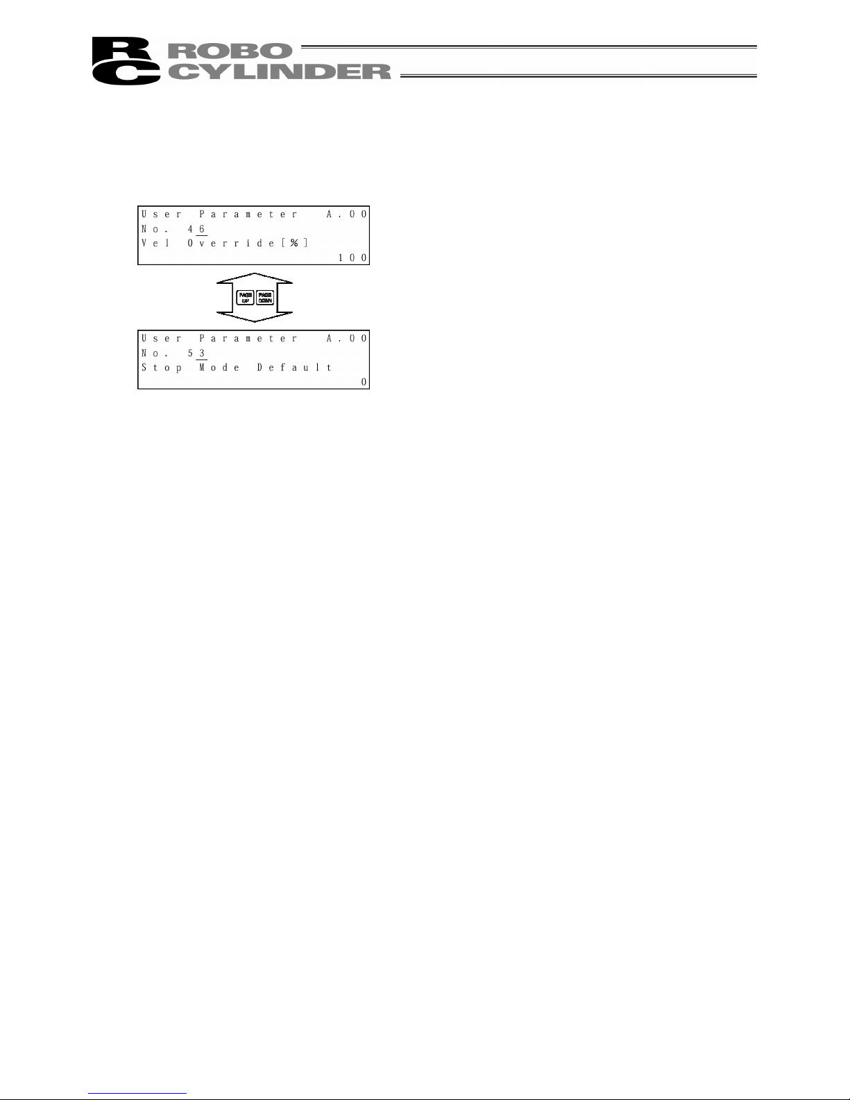
73
From previous page
Page 82

74
- When soft limit is modified at the customer site, please set a value which extends 0.3mm outside of the
effective area.
Example: When setting the effective area between 0mm~80mm
Soft limit + side: 80.3
Soft limit - side: -0.3
Caution:
Please restore the controller power after making parameter changes. Alternatively, reset
software in the case of any model which supports the software reset function. Although
pressing the emergency switch or port switch ON/OFF will rewrite the parameter, there may
be ones that will not be changed.
* Regarding parameter, please refer to the Controller Operating Manual.
8.8.2 Pause, Servo ON Input Enable and Disable Setting
(1) Pause
Pause input can be enabled or disabled with user parameter No. 15.
0: Enb, 1: Dsb
(2) Servo ON input
Servo ON input can be enabled or disabled with user parameter No. 21.
0: Enb, 1: Dsb
Soft Limit set in controller
Effective area
Jog Increment allowable range after homing
Approx.
0.1mm
Approx.
0.3mm
Approx.
0.3mm
Approx.
0.1mm
Page 83
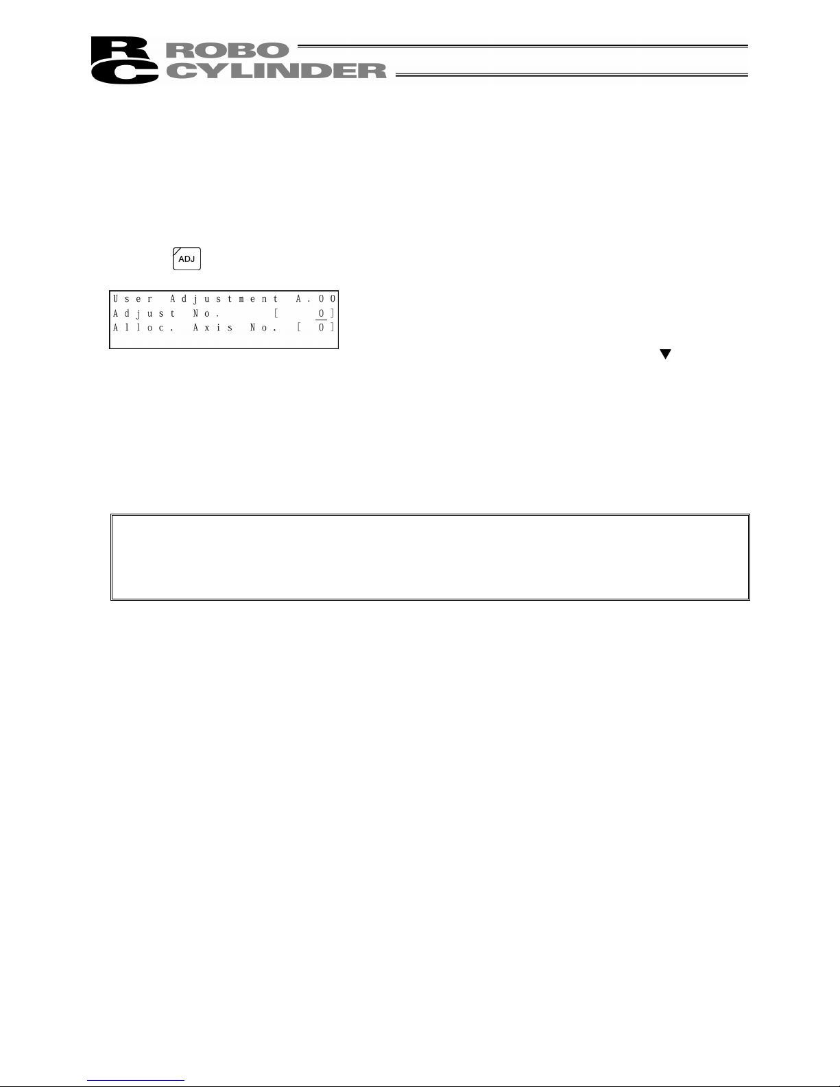
75
8-9 User Adjustment
8-9-1 Homing Operation and Axis Number Setting
Execute homing.
Set the axis number of the controller (PCON, ACON, RCP-RSI, RCP-RM1, etc.).
Press the
key.
Caution:
Caution: Do not input any numeric value other than 1, 2, 3, 4 and 5119 into Adjust No.
In the case of the RCP or RCP2 controller, 0 or 2 is set to parameter No. 25 (PIO pattern)
(when there is no servo ON input), do not input 92 into Adjust No., either. The controller will be
inoperable due to no servo ON input.
- If you input 1 into Adjust No. and press the Return
key, homing will be performed.
- Axis number setting
Move the cursor to Adjust No. with the
key. Input
the axis number and press the Return key.
Input 2 into Adjust No. and press the Return key.
* In the case of the PCON-C/CG and other controllers
for which the axis number is set with the rotary switch
on the front panel of the controller, axis number
setting is not available.
Page 84
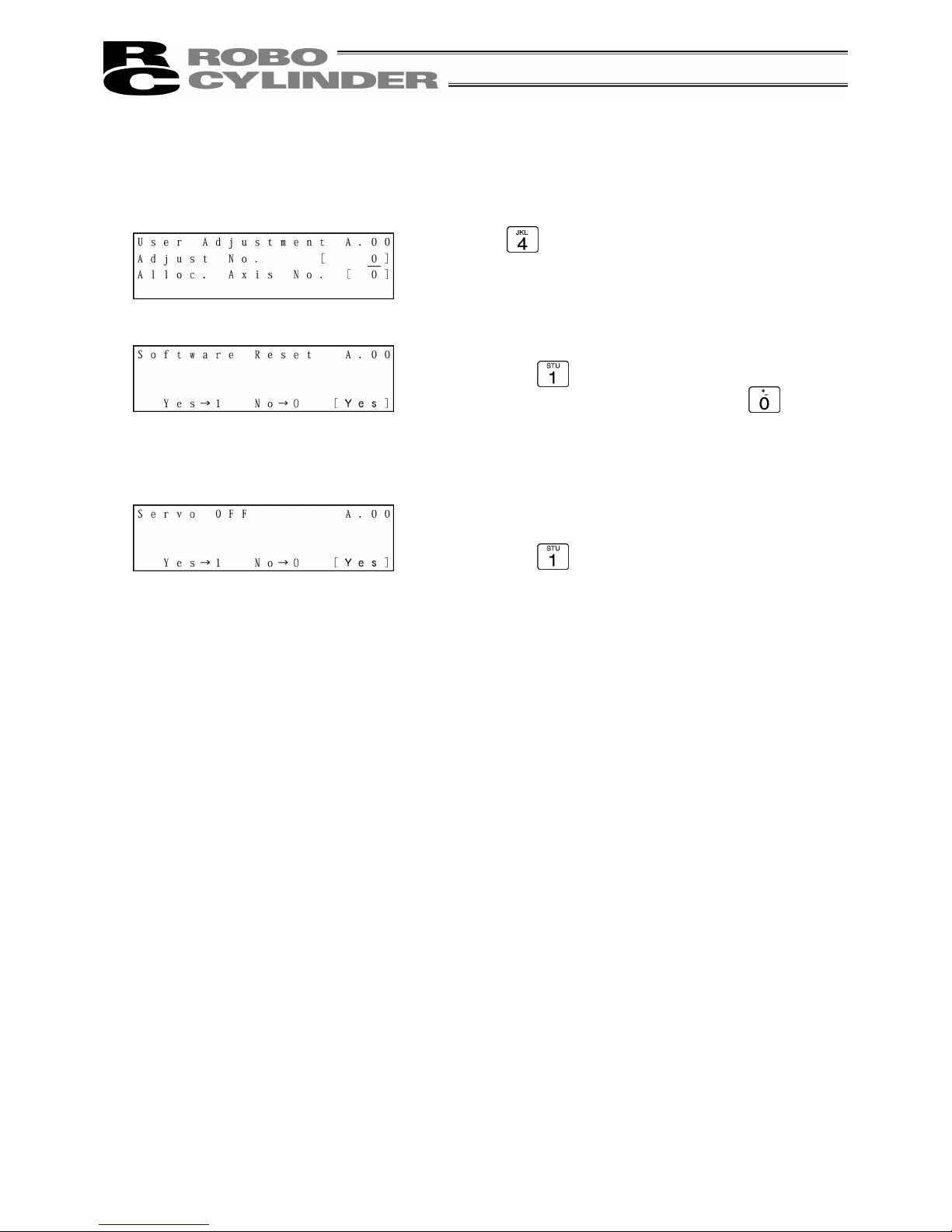
76
8-9-2 Software Reset
Software reset (controller restart) will be performed.
* The compatible models are PCON, ACON, SCON and RCP2.
Input into “Adjust No.” and press the Return key.
The screen will change to the Software Reset screen.
Press the
key and press the Return key.
(When not resetting software, press the
key and
press the Return key. The screen will return to the
Mode Select screen.)
When the servo is ON, the screen will change to the
Servo OFF confirmation screen.
Press the key and press the Return key. Then the
controller will restart and the screen will change to the
Mode Select screen. Since the servo is automatically
turned OFF, it is not required to turn SON input OFF.
Page 85

77
8-9-3 Error List Clear
All the contents of the error lists will be cleared.
* The compatible models are PCON, ACON and SCON.
Input into “Adjust No.” and press the Return key.
The screen will change to the Error List Clr screen.
Press the
key and press the Return key.
The error list will be cleared and the screen will return to
the Mode Select screen.
(When not clearing the error list, press the
key
and press the Return key. The screen will return to the
Mode Select screen.)
Page 86
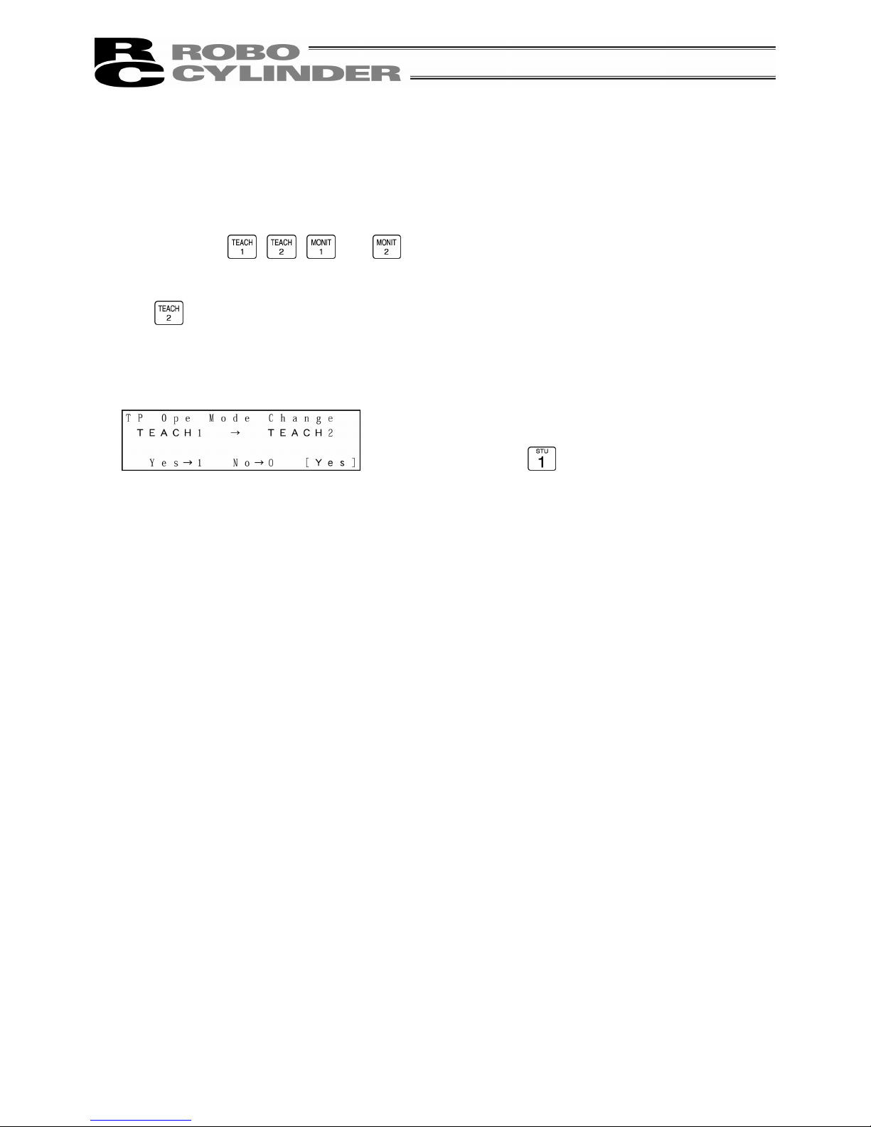
78
8-10 TP Operation Mode
The operation mode will be set in the manual mode (MANU).
The compatible models are PCON, ACON and SCON.
When changing the TP operation mode, press the key of the mode you want to change from
among the
, , and keys.
As an example, when changing from the TEACH1 mode status to the TEACH2 mode, press the
key.
The screen will change to the TP Ope Mode Change
data writing confirmation screen.
If you press the key and press the Return key, the
TP mode will change and the screen will change to the
Mode Select screen.
The LED of TEACH2, which is the TP operation mode
display LED, will light.
Page 87

79
Select the operation mode from the following 4 menu items:
- Teach 1: The LED is lit in the TEACH1 mode.
PIO Prh: Enables writing of position data, parameters, etc., in the controller and commands of the
actuator movement system.
SftyVel Efct: Keeps the maximum speed at the safety speed set for the parameter regardless of
position data.
- Teach 2: The LED is lit in the TEACH2 mode.
PIO Prh: Enables writing of position data, parameters, etc., in the controller and commands of the
actuator movement system.
SftyVel Non: Enables movement at the speed registered in position data.
- Monitor 1: The LED is lit in the MONIT1 mode.
PIO Prh: Enables monitoring only. Writing of position data, parameters, etc., in the controller and
commands of the actuator movement system are disabled.
SftyVel Efct: Keeps the maximum speed at the safety speed set for the parameter regardless of
position data.
- Monitor 2: The LED is lit in the MONIT2 mode.
PIO Prh: Enables monitoring only. Writing of position data, parameters, etc., in the controller and
commands of the actuator movement system are disabled.
SftyVel Non: Enables movement at the speed registered in position data.
Page 88

80
8-11 End
Before removing the Teaching Pendant from the RC controller, be sure to execute End.
Operation:
1. Press the
key for more than 2.5 seconds.
The screen will change to the TP end screen.
2. Press the
key to select “Complete.”
The screen display will change to “Non” and the Teaching Pendant will be disconnected from the
controller.
In the case of any controller with a PORT switch, turn the controller PORT switch to OFF and
remove the Teaching Pendant connector.
When reconnecting the Teaching Pendant to the controller without removing it, press the
key
to select “Reconnection.” Reconnection will be established and operation will start from the initial
screen.
Caution:
When multiple axes are connected with a controller link cable, after recycling power of a
controller that is not directly connected to the Teaching Pendant, please execute a
reconnect.
Caution:
In the case of the PCON or ACON controller with no AUTO/MANU switch, set the TP
operation mode to “Monitor 2” before removing the Teaching Pendant. (Refer to “8.10 TP
Operation Mode.”)
when the controller is set by connecting the Teaching Pendant to the gateway unit/SIO
converter, the conditions shown below occur.
•
If the Teaching Pendant is disconnected while the setting of “Teach 1” or “Teach 2”
remains, I/O will become invalid and control from PLC will become impossible.
•
If the Teaching Pendant is disconnected while the setting of “Monitor 1” remains, the
maximum speed will become the safety speed set for the parameter regardless of a
command from PLC.
Page 89
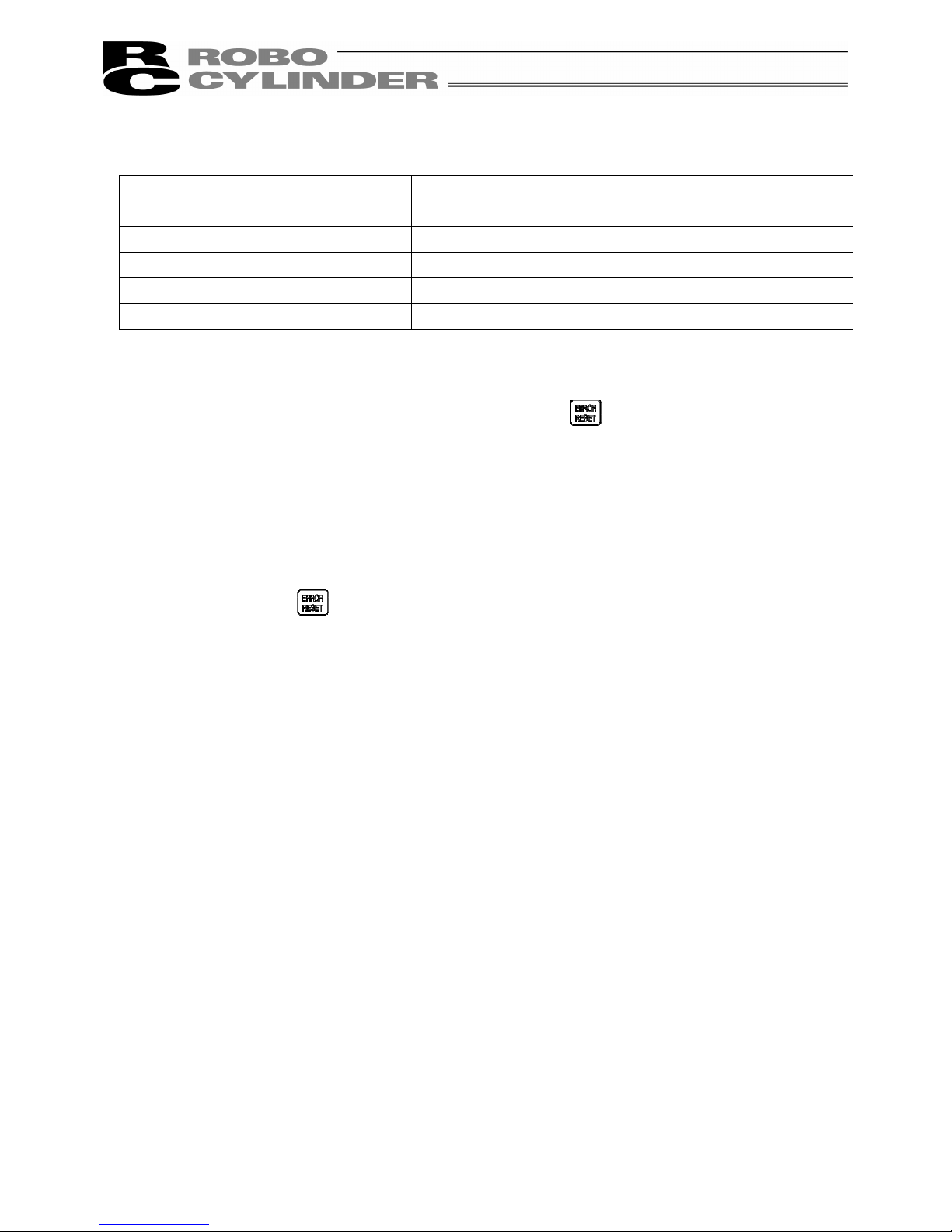
81
9. Message Area
In the message screen, content during error and warning will be displayed.
Code No. Error Label Error Reset Reference
000~07F Controller Warning Yes Controller rejects command
080-0FF Controller Error Note Error inside the controller
100~1FF DIP* Message Yes Input error, guide message, etc.
200~2FF DIP* Movement Release Yes Movement continuation impossible
300~3FF DIP Cold Start Error No DIP Power install or reconnect are necessary.
TP: Teaching Pendant
Note) Refer to “9.3 Controller Error.”
* In the case of any error with error reset “Yes,” if you press the
key, the error will be reset. All the
error lists in the controller can be cleared with error list clear of User Adjustment. (Refer to 8.9.3.)
9-1 Warning Label Error (Code No. 000h – 07Fh)
Warning message is cleared by recovery procedure as follows:
Release operation:
1. First, confirm the cause of the warning and resolve the problem.
2. Press down
key.
Warning is probably due to the following possibilities:
- RS485 communication abnormality
- Teaching Pendant operational mistake
a) RS 485 communication related abnormality
Indicates occurrence of any abnormality on the RS485 communication line.
Code No: 05Ah, 05Bh, 05Dh, 05Eh, 07Fh (Communication error detected by the controller)
Cause: (1) Teaching Pendant is in conflict with other devices (PLC or PC.)
For example, when move command is delivered by PIO signal from teaching
while communicating to other devices (PLC), “075h” will occur during homing.
(2) Influence by foreign noise or connections is not properly installed.
The Teaching Pendant and RC controller execute packet communication (move
instruction, data transfer, etc.) at all times. At this time, when data changes due
to noise, the RC controller will determine that it is incorrect data and will reject the
data.
Solution: (1) Confirm the above causes. In the case of frequent warning occurrences, please
separately set the signal cable and power line.
(2) Be sure to use one unit to operate the RC controller.
See to it that the Teaching Pendant will not conflict with the PIO signal.
Page 90

82
9-2 Teaching Pendant Message Level Error
Teaching Pendant Operational Mistake:
When you attempt to input an incorrect value, the message label error will occur.
Code No: 112h, 113h, 114h, 118h, 11Eh, 11Fh, etc. (keypad input value is incorrect.)
9-3 Controller Error
An alarm detected from the controller side can be displayed.
This is a serious error due to an abnormality related to servo control and electricity. Please read
through the RC Controller operating manual carefully for error compliance.
If any errors of the below code numbers occur, it is required to perform the error reset of the
controller (press the
key) to reset it in the case of a movement release level error. It is required to
perform the reset of the controller software in the case of a cold start level error. (Refer to 8.9.2.) With
regard to the controllers not equipped with the software reset function, it is required to turn on the
power again.
Code No: 0B0h, 0B1h, 0B8h, 0B9h, 0BBh, 0BCh, 0BDh, 0BEh
0C0h, 0C1h, 0D0h, 0D1h, 0D8h, 0E0h, 0E8h, 0E9h, 0EAh, 0F8h
For details of error codes, refer to the operating manual of the controller you use.
Page 91
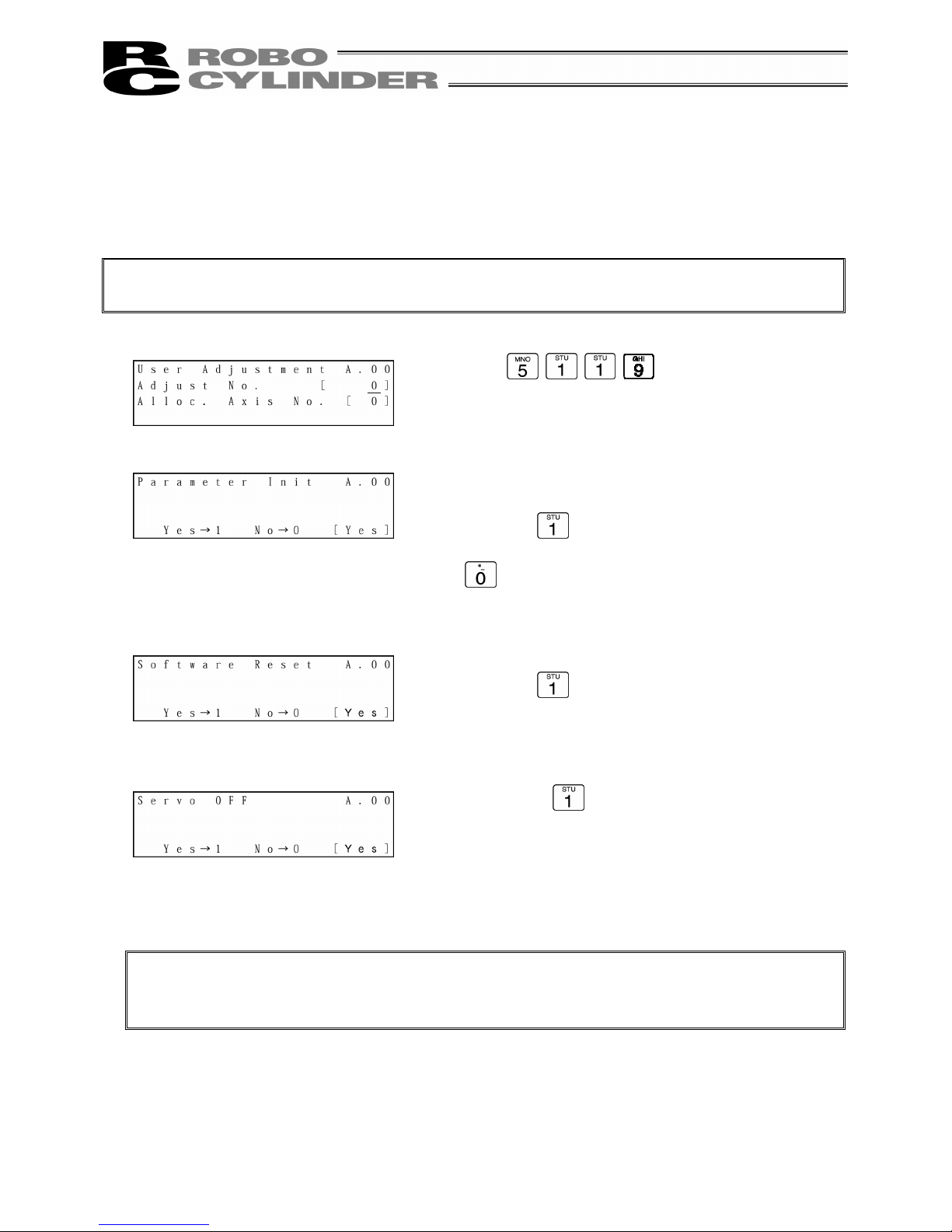
83
Appendix
* Appendix
Parameter (Shipment) Initialization Method
Parameters will be changed (initialized) to shipment parameters.
The compatible models are PCON, ACON and SCON.
Caution:
Please take note that if parameter (shipment) initialization is performed, user-set parameters will
be changed to shipment parameters.
Caution:
If software reset has not been executed, parameters have been rewritten to shipment
parameters but operation will not be performed with shipment parameters.
After the next reset or power-on, the parameters will be effective.
Input
for “Adjust No.” and press
the Return key.
The screen will change to the Parameter Init execution
confirmation screen.
Press the
key and press the Return key.
(When not performing parameter initialization, press the
key and press the Return key. The screen will
return to the Mode Select screen,)
The screen will change to the Software Reset screen.
Press the
key and press the Return key.
When the servo is ON, the screen will change to the
Servo OFF confirmation screen.
Press the
key and press the return key.
Parameters will be initialized and become shipment
parameters.
Since the servo is automatically turned OFF, it is not
required to turn SON input OFF.
Page 92

84
Appendix
Teaching Pendant Error Messages
As an example, if an input value is larger than the set range during MDI-mode position data input, the following
error screen will be displayed:
If you press the
key, the screen will return from the error display screen to the previous screen.
In this case, the screen will return to the MDI-mode position data input screen.
The screen will return to the previous screen from the error display screen even using the
key. However,
in this case, controller alarm reset will be performed simultaneously.
(Note) Since emergency stop, motor voltage reduction and absolute battery voltage reduction are not
alarms, the alarm code will display “- - - -” sign.
Listed in the table below are Teaching Pendant specific errors.
For error of controller, refer to the Operating Manual of each controller.
Code Message name Description
112 Input Incorrect Error An incorrect value was entered for a parameter.
(Example) 9601 was entered as the serial communication speed by mistake. Reenter a
correct value.
113
114
Input Under Error
Input Over Error
The entered value is smaller than the setting range.
The entered value is larger than the setting range.
Refer to the actuator specifications or parameter table and reenter a correct value.
115 Homing Incomplete The current position was written when home return was not yet completed.
Execute home return again.
117 No Move Data Target position is not set under the selected position number.
Enter the target position first.
11E Pair Data Mismatch The values indicating the magnitude relationship of a pair of data are incorrect.
(Example) The same value was entered in both the parameters for + and – soft limits.
Reenter correct values.
11F Absolute Value Error The minimum movement toward the target position is determined by the lead length of
the drive system and resolution of the encoder.
This message indicates that the entered target value is smaller than the minimum
movement.
(Example) If the actuator is the RCP2 Series actuator and the lead length is 20 mm, the
encoder’s resolution is 800 pulses and accordingly the minimum movement
becomes 20÷800 = 0.025 mm/pulse. In this case, this message will be
displayed if 0.02 mm is entered at the target position.
121 Push search end over The final position in push operation exceeds the soft limit.
This has no negative effect if the actuator contacts the work. If the actuator misses the
work, however, the soft limit will be reached and this message is displayed as a warning.
Change either the target position or positioning band.
Page 93

85
Appendix
Code Message name Description
122 Allocate, multi-axes connect Address was assigned when multiple axes were connected.
Assign each address only when one axis is connected.
133 Change to axis number
prohibit
In the case of the PCON-C/CG, ACON-C/CG, or SCON controller, the axis number is set
with the rotary switch on the front panel.
It cannot be set with the Teaching Pendant.
-
-
-
-
Change to axis number OK
Controller initialize OK
Home Change All Clear
IO function changed
These messages are displayed to confirm operation.
(They do not indicate an operation error or other abnormality.)
201 Emergency Stop An emergency stop condition was detected. (This is not an error.)
It is displayed for PCON, ACON and SCON.
- Emergency Stop This message indicates an emergency stop condition. (This is not an error.)
It is displayed for PCON, ACON and SCON.
- Motor voltage drop This message indicates the motor drive power shut-off condition due to an open circuit
between the MPI terminal and MPO terminal.
(Note) If this message occurs when a circuit between the MPI terminal and MPO
terminal is closed, a controller failure is suspected.
- ABS battery voltage drop This message indicates that the battery voltage dropped when the power was turned
ON.
20A During movement, Servo OFF This message indicates that the servo ON signal (SON) was turned OFF by the PLC
while the actuator was moving and that the servo turned OFF and the movement was
disabled as a result.
20C During movement, CSTR-ON This message indicates that the start signal (CSTR) became “1” by the PLC while the
actuator was moving and that duplicate movement commands occurred as a result.
20D During movement, STP-OFF This message indicates that the temporary stop signal (*STP) was turned OFF by the
PLC while the actuator was moving and the movement was disabled as a result.
20E Soft limit over This message indicates that a soft limit was reached.
210 HOME-ON during operation This message indicates that a home return signal (HOME) became ON from PLC and
duplicate movement commands occurred during movement operation.
211 JOG-ON during operation This message indicates that a home return signal (HOME) became ON from PLC and
duplicate movement commands occurred during movement operation.
220 Write in AUTO prohibited This messages indicates that parameter writing operation was performed in the AUTO
mode of the PCON-C/CG, ACON-C/CG, or SCON controller.
221 Write in Monitor mode
prohibited
This message indicates that position data or parameter writing operation was performed
in the Monitor mode.
222 Operation in AUTO prohibited This message indicates that actuator movement operation was performed in the AUTO
mode.
223 Operation in Monitor mode
prohibited
This message indicates that actuator movement operation was performed in the Monitor
mode.
301
302
304
305
306
308
30A
30B
Over Run Error (M)
Framing Error (M)
SCIR-QUE OV (M)
SCIS-QUE OV (M)
R-BF OV (M)
Response Time Out (M)
Packet R-QUE OV
Packet S-QUE OV
These messages indicate an error in the serial communication with the controller.
Cause: [1] Garbage data due to the effect of noise
[2] Duplicate slave numbers when multiple controllers are controlled by serial
communication.
Action: [1] Adjust the wiring in a manner eliminating the effect of noise and review the
installation of equipment, etc.
[2] Change the slave numbers to avoid duplication.
If the message is still displayed after taking the above actions, please contact IAI.
Page 94

86
Appendix
Code Message name Description
307
309
Memory Command Reject
Wright Address Error
This message indicates that the command was refused in the serial communication with
the controller.
This message indicates that an indeterminate WRITE address error occurred in the
serial communication with the controller.
These conditions do not occur in normal operation. Should they occur, record the entire
error list before cutting off the power for use in the cause investigation. Also, contact IAI.
30C No Connect Error This message indicates that no controller axis number is recognized.
Cause: [1] The controller is not operating properly.
[2] Only the supplied communication cable (SGA/SGB) is disconnected.
[3] If a SIO converter is used, 24V is supplied to the converter but the link cable
is not connected.
[4] The ASDRS switch settings are duplicated by mistake when multiple
connectors are linked.
Action: [1] Check if the RDY lamp on the controller is lit. If the lamp is not lit, the
controller is faulty.
[2] If a spare Teaching Pendant is available, replace the current pendant with
the spare unit, or with a PC and see if the message disappears.
[3] Supply power after connecting the link cable between the converter and
controller.
[4] Make sure the ADRS switch settings are not duplicated.
If the message is still displayed after taking the above actions, please contact IAI.
Page 95

Page 96

Catalog No.: MJ0178-1A (April 2007)
IAI America Inc.
Head Office: 2690W 237th Street Torrance, CA 90505
TEL (310) 891-6015 FAX (310) 891-0815
Chicago Office: 1261 Hamilton Parkway Itasca, IL 60143
TEL (630) 467-9900 FAX (630) 467-9912
New Jersey Office: 7 South Main St., Suite-F, Marlboro, NJ 07746
TEL (732) 683-9101 FAX (732) 683-9103
Home page: www.intelligentactuator.com
IAI Industrieroboter GmbH
Ober der Röth 4, D-65824 Schwalbach am Taunus, Germany
TEL 06196-88950 FAX 06196-889524
The prices, specifications, dimensions and other information provided in this manual are subject to change without notice for
purposes of product improvement.
Copyright © 2007 April IAI Corporation. All rights reserved.
 Loading...