

FFeeaattuurreess
AApppplliiccaattiioonnss
Programmable Charge Current Up to 800mA
No MOSFET, Sense Resistor or Blocking
Diode Required
Complete Linear Charger in ThinSOTTM
Package for
Single Cell Lithium-Ion Batteries
Constant-Current/Constant-Voltage
Operation with
Thermal Regulation* to Maximize Charge
Rate
Without Risk of Overheating
Charges Single Cell Li-Ion Batteries Directly
from USB Port
Preset 4.2V Charge Voltage with 1%
Accuracy
Automatic Recharge
60uA Supply Current in Shutdown
2.9V Trickle Charge Threshold
Two sides of LED showing
Available in 6-Lead SOT-23 Package
Charger for Li-Ion Coin Cell Batteries
Portable MP3 Players, Wireless Headsets
Bluetooth Applications
Multifunction Wristwatches
SSttaannddaalloonnee LLiinneeaarrLLii--IIoonn BBaatttteerryy CChhaarrggeerr
n
DDeessccrriippttiioon
The IA4054 is a complete constant - cu r ren t / co
nstantvoltage linear charger for single cell lithi
um-ion batteries. Its ThinSOT package and lo
w external component coun t make the IA4054
3 ideally suited for portable applications. Furth
ermore, the IA4054 is specifi cal ly designed
to work within USB power specificat ions.
No external sense resistor is needed, and no
blocking diode is required due to the internal
MOSFET architecture. Thermal feedback
regulates the charge current to limit the die
temperature during high power operation or high
ambient temperature. The charge voltage is fixed
at 4.2V, and the charge current can be
programmed externally with a single resistor. The
IA4054 automatically terminates the charge
cycle when the charge current drops to 1/10th the
programmed value after the final float voltage is
reached.
When the input supply (wall adapter or USB
supply) is removed, the IA4054 automatically
enters a low current state, dropping the battery
drain current to less than 1uA. The IA4054 can
be put into shutdown mode, reducing the supply
current to 60uA. Other features include charge
current monitor, undervoltage lockout, automatic
recharge and a status pin to indicate charge
termination and the presence of an input voltage.
The IA4054 converters are available i n the
industry standard SOT-23-6 power
packages (or upon request).
HX1001
II2I
IA4054
1
IA4054
OOrrddeerr IInnffoorrmmaattiioonn
IA4054
SYMBOL DESCRIPTION
①
②
① ②
:
Denotes Output voltage:
4.2V
Denotes Package Types:
E: SOT-23-6
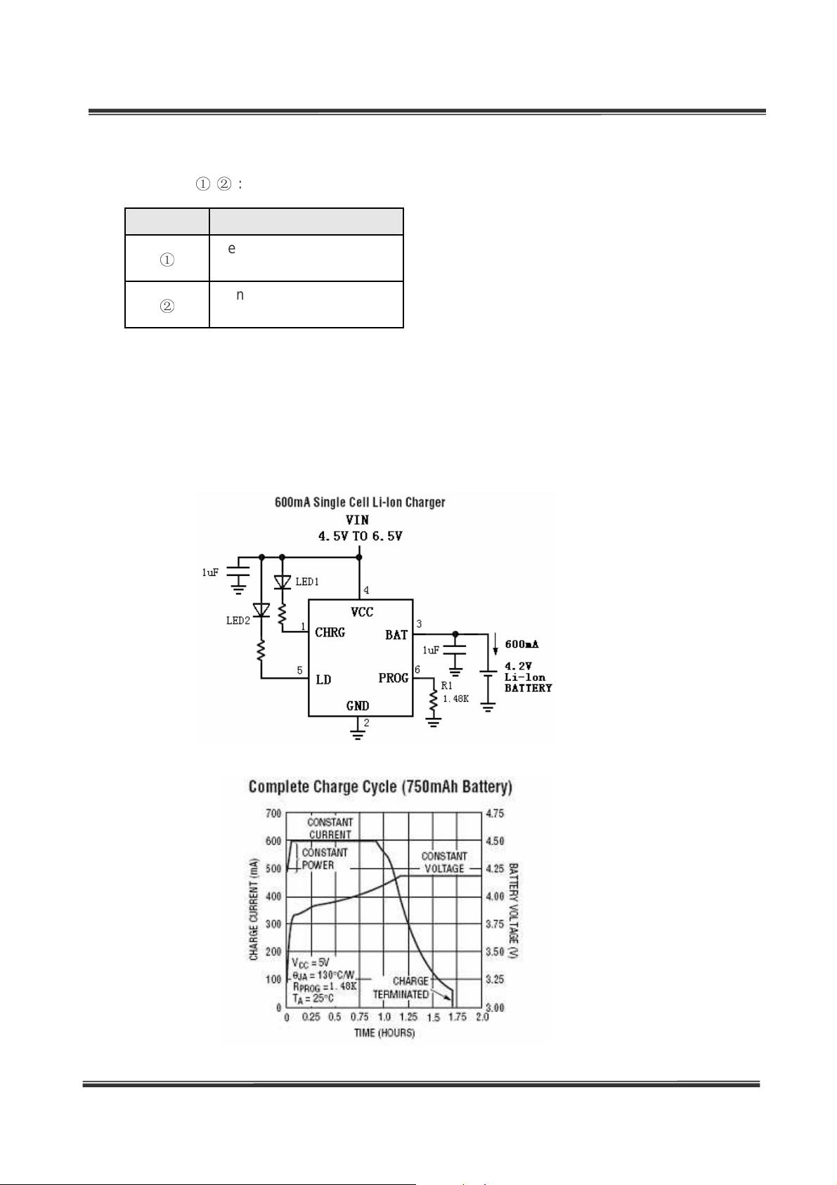
TTyyppiiccaall AApppplliiccaattiioon
n
2
IA4054
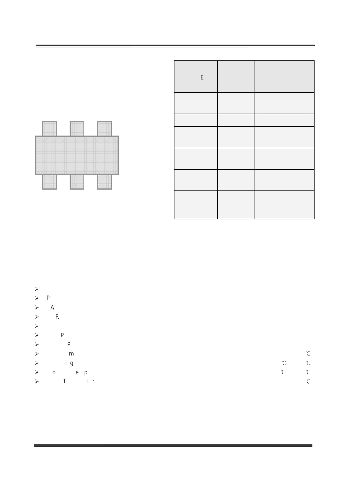
PPiinn AAssssiiggnnmmeenntt
6 5 4
1 2 3
PIN
NUMBER
SOT-23- 6
1 CHRG
2 GND
3 BAT
4 PROG
5 LD
6 VCC
PIN NAME FUNCTION
Open-Drain Charge
Status Output
Ground
Charge Current
Output
Positive Input
Supply Voltage.
Open-Drain Charge
Status Output
Charge Current
Program, Charge
Current Monitor and
Shutdown Pin
Absolout Maximum Ratings
Input Supply Voltage (VCC) ......................................................................................... –0.3V to 10V
PROG............................................................................................................... – 0.3V to VCC + 03V
BAT .......................................................................................................................... –0.3V to 8V
CHRG..................................................................................................................... –0.3V to 10V
BAT Short-Circuit Duration ............................................................................................. Continuous
BAT Pin Current .................................................................................................................... 800mA
PROG Pin Current ................................................................................................................ 800uA
Maximum Junction Temperature .............................................................................. 125
Operating Ambient Temperature Range............................................................... –40℃ to 85℃
Storage Temperature Range ………………………………………….................. –65 ℃to 125℃
Lead Temperature (Soldering, 10 sec).................................................................................. 300℃
℃
3

IA4054
EElleeccttrriiccaall CChhaarraacctteerriissttiiccss
Operating Conditions: TA=25 , ℃VCC=5V unless otherwise specified.
SYMBOL PARAMETER
VCC Input Supply Voltage
Input Supply Current
ICC
Regulated Output
V
FLOAT
I
BAT
(Float) Voltage
BAT Pin Current
Charge Mode , R
Standby Mode (Charge
Terminated) l
Shutdown Mode (R
Connected,VCC < V
VUV)
0
℃≤
R
PROG
R
PROG
Standby Mode, V
Shutdown Mode (R
Connected)
Sleep Mode, VCC = 0V
CONDITIONS MIN TYP MAX UNITS
= 10k
PROG
Not
PROG
, or V
BAT
T
≤
85℃
, I
A
= 10k, Current Mode
= 2k, Current Mode
= 40mA 4.15 4.2 4.24 V
BAT
= 4.2V
BAT
PROG
CC
Not
4.5 5.0 6.5 V
<
83
410
70
45
65
89
445
7.3
7.2
0.3
470
97
15
1
µ
A
µ
A
µ
A
mA
mA
µ
A
µ
A
µ
A
I
Trickle Charge Current V
TRIKL
VCC – V
V
ASD
I
TERM
V
PROG
RON Efficiency
Threshold Voltage
C/10 Termination
Current Threshold
PROG Pin Voltage R
Lockout
BAT
< V
BAT
VCC from Low to High
VCC from High to Low
R
= 2k
PROG
= 10k, Current Mode 0.94 1.02 1.08 V
PROG
Power FET “ON” Resistance
(Between VCC and BAT)
TRIKL
, R
= 2k 15 39 65 mA
PROG
45
660 mΩ
5
18
mV
mA
4

IA4054
AApppplliiccaattiioonn IInnffoorrmmaattiioonn
PIN ASSIGNMENT
CHRG (Pin 1): Open-Drain Charge Status
Output. When the battery is charging, the CHRG
pin is pulled low by an internal N-channel
MOSFET. When the charge cycle is completed,
high impedance is forced to the CHRG pin and
LD (pin 5) is pulled low, indicating an “AC
present” condition. When the IA4054 detects an
reverse battery (VBAT>VCC) lockout or no AC
condition, Both CHRG and LD are forced high
impedance.
GND (Pin 2): Ground.
BAT (Pin 3): Charge Current Output. It should
be bypassed with at least a 1uF capacitor.It
Provides charge current to the battery and
regulates the final float voltage to 4.2V. An
internal precision resistor divider from this pin
sets the float voltage which is disconnected in
shutdown mode.
VCC (Pin 4): Positive Input Supply Voltage.
Provides power to the charger. VCC can range
from 4.25V to 6.5V and should be bypassed with
at least a 1uF capacitor. When VCC drops to
within 30mV of the BAT pin voltage , the
IA4054
enters shutdown mode, dropping IBAT to less
than 2 uA.
LD(Pin 5): Open-Drain Charge Status Output.
See CHRG pin (Pin 1).
PROG (Pin 6): Charge Current Program,
Charge Current Monitor and Shutdown Pin. The
charge current is programmed by connecting a
1% resistor, RPROG, to ground. When charging
in constant-current mode, this pin servos to 1V. In
all modes, the voltage on this pin can be used to
measure the charge current using the following
formula: IBAT = (VPROG/RPROG)*890,The
PROG pin can also be used to shut down the
charger.Disconnecting the program resistor from
ground allows a weak current to pull the PROG
pin high. When it reaches the 1.21V shutdown
threshold voltage, the charger enters shutdown
mode, charging stops and the input supply
current drops to 65uA. Reconnecting RPROG to
ground will return the charger to .normal
operation.
5

IA4054
PPaacckkaaggiinngg IInnffoorrmmaattiioonn
SOT-23-6 Package Outline Dimension
Symbol
A 1.050 1.250 0.041 0.049
A1 0.000 0.100 0.000 0.004
A2 1.050 1.150 0.041 0.045
b 0.300 0.500 0.012 0.020
c 0.100 0.200 0.004 0.008
D 2.820 3.020 0.111 0.119
E 1.500 1.700 0.059 0.067
E1 2.650 2.950 0.104 0.116
e 0.950(BSC) 0.037(BSC)
e1 1.800 2.000 0.071 0.079
L 0.300 0.600 0.012 0.024
Dimensions In Millimeters Dimensions In Inches
Min Max Min Max
6

 Loading...