

HZ Sound Systems Q-ZONE Owner's Manual
6 WAY 1U Hi RACK MOUNT ZONER
OWNERS MANUAL
For EUROPEAN220V -230V
OPERATION
Hz INTERNATIONAL LTD COMBE HOUSE - STOKE ST MICHAEL -BATH - SOMERSET – ENGLAND


UNPACKING
The Q – Zone has been designed as a rugged piece of professional equipment. It contains a high s pecification modern electronic PCB assembly
and should be treated with care.
The packaging of the unit is specifically designed to safely transport this product. In the unlikely event of the product requiring servicing, it is best to
return it in this packaging.
All units are factory set for 220-230v operation. Units factory made for 110/120V supply are clearly marked on the back and should not be
connected to any higher voltage power source.
FITTING A POWER LEAD PLUG
The wires in the IEC/CEE mains lead are coloured: Earth: Green/Yellow Neutral: Blue Live: Brown
MOUNTING THE UNIT
This unit has been designed for rack mounting use, in a Racking enclosure made to BS5954, I EC297 or Din 41494 standards.
DO NOT USE RACKS NEAR HEATING DUCT OUTLETS, APPLIANCES OR RADIATORS.
Care is required when installing these units in a rack. It is advisable to put the Rack on its back, then place all the other equipment being fitted
to the rack into it before tightening the retaining screws.
Contents:
1. OVERVIEW
2. USING THE Q-ZONE
3. SIGNAL INPUT CONTROLS
4. SPECIAL CONNECTIONS
5. ZONE OUTPUTS
6. TROUBLE SHOOTING
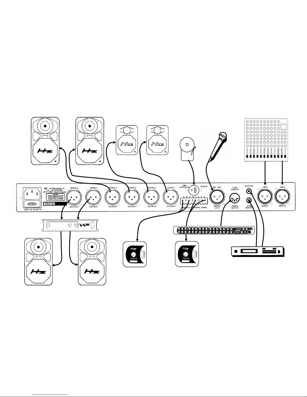
OVERVIEW
Microphone
CD Or DVD Players
Power Amp
FIRE
Area 5
Area 6
Area 4
Active
Speaker
Area 3
Active
Speaker
Area 2
Active
Satellite
Area 1
Active
Satellite
Q-Zone
Remote
Volume
Ch 1
Remote
Volume
Ch 5
Performance
Mixer
Fire
Alarm
With typical Installation Equipment
 Loading...