

HZ Sound Systems DPX1500 Owner's Manual

generation
III
DUAL CHANNEL HEXFET
AUDIO POWER AMPLIFIER
WITH CLIP LIMITING & TAPS
CONTROL
OWNERS MANUAL
For EUROPEAN
220V -230V
OPERATION
Hz
INTERNATIONAL LTD COMBE HOUSE - STOKE ST MICHAEL -BATH - SOMERSET - ENGLAND
DPx1500

CONTENTS
GETTING STARTED
1. Preface
2. Installation
3. Connections
4. Input Cables
5.
Output Connections
6. Power Connection
OPERATION:
1. SIGNAL/PEAK INDICATOR
2. MONO/STEREO MODE
3. LOAD/ FAULT INDICATOR ALARM
4. POWERING UP
AMPLIFIER MAINTENANCE
FAULTS AND THEIR LIKELY CAUSES
TECHNICAL DATA
1
GETTING STARTED
PREFACE
Although the power amplifier is a rugged piece of professional audio equipment and is heavy, it is also a high
specification modern electronic assembly and should be handled with care.
The packaging of the unit is specifically designed to safely transport this product. In the unlikely event of the
product requiring servicing, this packaging is the safest way to transport it.
All units are factory set for 220-230v operation.
Units factory made for 110/120V supply are clearly marked on the back and should not be connected to any
higher voltage power source.
INSTALLATION
This power amplifier has been designed for rack mounting use, in a Racking enclosure made to BS5954, IEC297
or Din 41494 standards.
a. The unit must be mounted in the horizontal position with clear cool air flow of 10cm around each vent.
DO NOT STAND OR USE RACKS NEAR HEATING DUCT OUTLETS, APPLIANCES OR RADIATORS.
If the rack is placed in an enclosed area (cupboard etc.) make sure that there is plenty of rear ventilation
and the air is not recycling.
b. Rack mounting - Ears are provided for both front and rear support; a choice of mounting position is given
on the front brackets ( either proud & level with the front panel or sunk by 20mm and flush with the front
escutcheon.)
c. Care is required when installing these units in a rack. It is advised to put the Rack on its back, then place all
the equipment being fitted into it before fitting retaining bolts to avoid unnecessary handling damage.
Rear support brackets are strongly recommended to be used on each unit, to avoid transit damage.
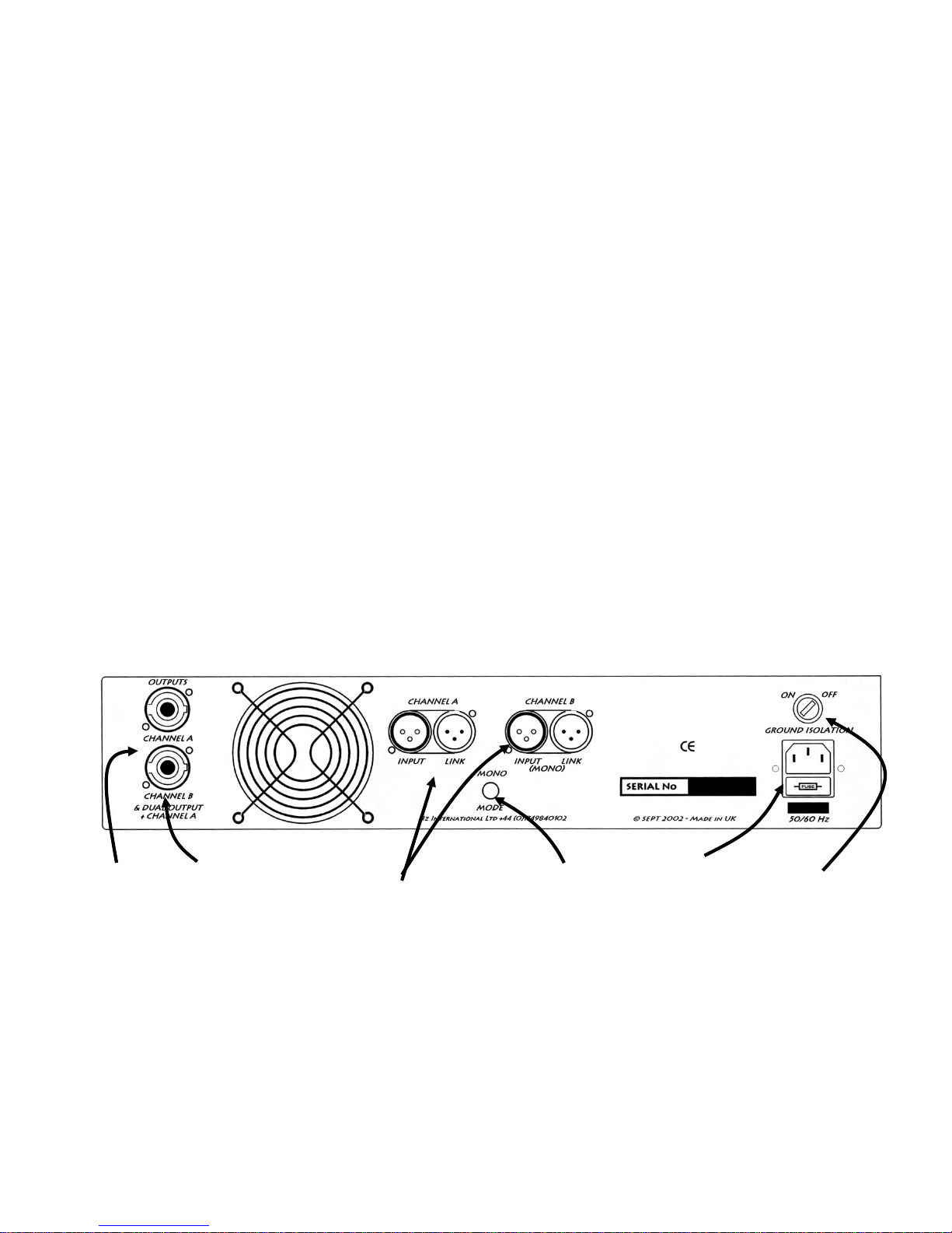
CONNECTIONS & SWITCHES
On the back of the DPX amplifier you will find the following connection sockets:A. Mains inlet: To connect the unit, via a mains lead, to the mains power supply.
B.
Input & Link XLR's: Provide Inputs to the amplifier. & parallel output hook up links
C.
Speakon’s for connection to loudspeakers.
D.
A Combined output of Ch A & B for 4 way cable hookup A = +2 / -2 B = +1 / -1
E. Ground Isolation Switch: Couples or de-couples the input ground, to avoid hum loops
F. Mono mode switch: For switching between mono and dual channel modes.
2
A
Mains
inlet
D
Ground
Isolation
Switch
F
Mono
Mode
Switch
B
Input & Link
XLR’s
C
Output
‘Speakons’
D
Combined
output
‘Speakon’
 Loading...