

Page 1
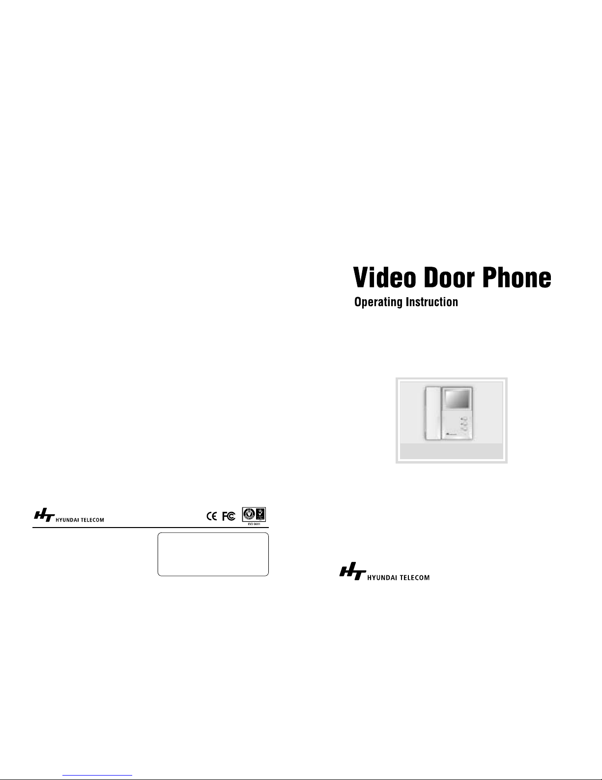
For your protection, Please read these instructions completely and keep it for future reference
HA-201 / HAC-201
Hanmi Building 45, Pang-E Dong, Songpa-Ku
Seoul 138-724, Korea
Tel 82.2.2240.9234/9271/9273
Web site : www.hyundaitel.com
6320000033H
Hyundai Telecom Printed in Korea
Page 2

WARNING
To prevent injury, the following safety precautions should be observed in the
installation, use and servicing of the set.
This symbol is intended to alert the user to the presence of uninsulated
“dangerous voltages” within the product’s enclosure that may be of
sufficient magnitude to constitute a risk of electric shock to the user.
This symbol is intended to alert the user to the presence of important
operating and maintenance (servicing) instructions in the literature
accompanying the appliance.
For the customers
This equipment has been tested and found to comply with the limits for a Class B
digital device, pursuant to Part 15 of the FCC Rules.
These limits are designed to provide reasonable protection against harmful
interference in a residential installation. This equipment generates, uses, and can
radiate radio frequency energy and, if not installed and used in accordance with
the instructions, may cause harmful interference to radio communication. There is
no guarantee that interference will not occur in a particular installation. If this
equipment does cause harmful interference to radio or television reception, which
can be determined by turning equipment off and on. The user is encouraged to
try to correct the interference by one or more of the following measures:
- Reorient or relocate the receiving antenna.
- Increase the separation between the equipment and receiver.
- Connect the equipment into an outlet on a circuit different from that to which
the receiver is connected.
- Consult the dealer or an experienced radio/TV technician for help.
Note : Change or modification not expressly approved by the party responsible for
compliance could void the user’s authority to operate the equipment.
CAUTION
: TO REDUCE THE RISK OF ELECTRIC
SHOCK, DO NOT REMOVE COVER (OR BACK). NO
USER SERVICEABLE PARTS INSIDE, REFER
SERVICING TO QUALIFIED SERVICE PERSONNEL
CAUTION
RISK OF ELECTRIC SHOCKS
DO NOT OPEN
Page 3
HYUNDAI Video Door Phone | HA-201 / HAC-201 2|3
SAFEGUARDS
1. Read Instructions
All the safety and operating instructions should be read before the unit is
operated.
2. Retain Instructions
The safety and operating instructions should be retained for future reference.
3. Follow Instructions
All operating instructions, maintenance and all warnings should be followed.
4. Cleaning
Turn off the power to the unit before cleaning. Do not use liquid or aerosol
cleaners. Use a dry cloth for the body of unit.
5. Attachments
Do not use attachments not recommended by the unit product manufacturer,
as they may be hazardous or cause damage.
6. Heat and Moisture
Do not expose this unit to direct sunlight or rain for reliable operation.
7. Installation
Do not install this unit on an unstable place (hot, cold, humid or excessive dust).
Use only with a mounting accessory recommended by the manufacturer or
sold with the unit. Follow instructions of the manufacturer and qualified service
personnel when installing this unit.
8. Ventilation
Slots and openings in the cabinet are provided for ventilation to ensure reliable
operation of the unit and to protect it from overheating. These openings must
not be blocked or covered. Never place your unit on a bed, sofa, rug, or similar
surface or on or near a radiator or heat register. This unit should not be placed
in a built-in installation such as a bookcase or rack unless proper ventilation is
provided.
9. Power Sources
This unit should be operated only from the type of power source indicated on
the label. If you are not sure of the type of power supplied to your home,
consult your appliance dealer or local power company. To operate the unit by
battery of another power source, consult the operating instructions.
10. Grounding and Polarization
This unit may be equipped with either a polarized 2-wire DC adaptor line plug
(a plug having one blade wider than the other) or a 3-wire grounding type
plug, a plug having a third (grounding) pin. The 2-wire polarized plug will fit into
the power outlet only one way. This is a safety feature. If you are unable to insert
the plug fully into the outlet, try reversing the plug. If the plug still fails to fit,
contact your electrician to replace your outlet. Do not defeat the safety
purpose of the polarized plug.
11. Overloading
When using this product, do not overload the power outlets or extension cords
as this could cause fire or electric shock.
12. Accessories
Do not place this unit on an unstable cart, stand, tripod, bracket, or table. If the
unit falls, it could cause injury or damage to the system.
13. Object and Liquids
Never push objects of any kind into this unit through the openings. Never spill
liquid of any kind on the unit.
14. Servicing
Do not attempt to service this unit yourself as opening or removing covers may
expose you to dangerous voltages or other hazards. Refer all servicing to
qualified service personnel.
15. Power Line
The system should not be located near power lines or electric lights or power
circuits.
16. Damage Requiring Service
Unplug this unit from the wall outlet and refer servicing to a qualified service
person if any of the following occur :
a. If the power supply cord or plug is damaged.
b. If any liquid has been spilled into or objects have fallen in the unit.
c. If the unit has been exposed to rain or water.
d. If the unit has been dropped or otherwise damaged.
e. If the equipment exhibits a distinct change in performance.
17. Replacement Parts
When replacement parts are required, use replacement parts specified by the
manufacturer.
Page 4
UNIT & COMPONENTS
TABLE OF CONTENTS
UNIT & COMPONENTS 6
PARTS CHECK-LIST 8
INSTALLATION 10
WIRING DIAGRAM 12
OPERATION 14
TROUBLE SHOOTING 16
SPECIFICATIONS 17
Important Notice
Always use discretion when installing video and audio surveillance equipment especially
when there is perceived privacy, or an expectation of privacy. Inquire regarding federal,
state and/or local regulations applicable to the lawful installation of video and/or audio
recording or surveillance equipment. Party consent may be required.
Page 5
HYUNDAI Video Door Phone | HA-201 / HAC-201 6|7
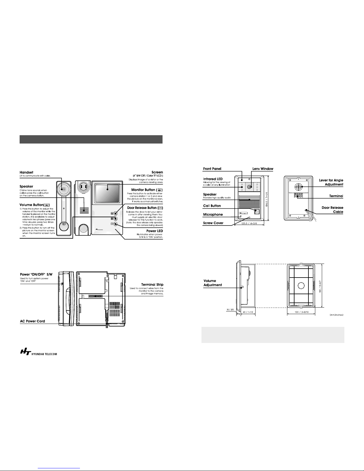
UNIT & COMPONENTS
Monitor
Side & Bottom panel
UNIT & COMPONENTS
Camera (HCB-300/HCC-300)
Side & Bottom panel
Note: If the camera lens angle requires adjustment, simply position the lever of angle
adjustment and then tighten the screw on it with a philip screwdriver before
installation.
Page 6
INSTALLA TION
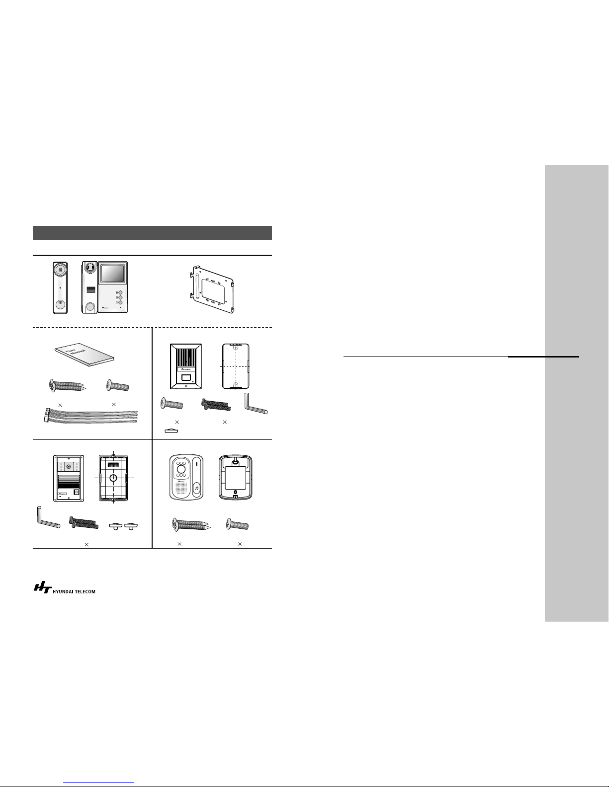
PARTS CHECK -LIST
The parts shown below are provided by the manufacturer and are enclosed in the box.
Handset
HCB-300/HCC-300
HCB-150/HCC-150
Bracket
Flush Box
Tamper Proof
Screws (3
30 mm)
Tamper Proof
Screws (3
8 mm)
Monitor Mounting Screws
(3
8 mm)
Mounting Screw
(4
20 mm)
Mounting Screws
(4
20 mm)
Camera Mounting
Screw (3 8 mm)
Wrench
Rubber screw
Covers
Rubber screw Cover
Main
Camera (HCB/HCC-300) Camera (HCB/HCC-150E)
Camera (HCB/HCC-500)
User Manual
Cable
Mounting Bracket
< Figure 1>
HCB/HCC-500
Wall Bracket
Screw(4
30mm)
Wrench
Page 7
HYUNDAI Video Door Phone | HA-201 / HAC-201 10|11
INSTALLATION
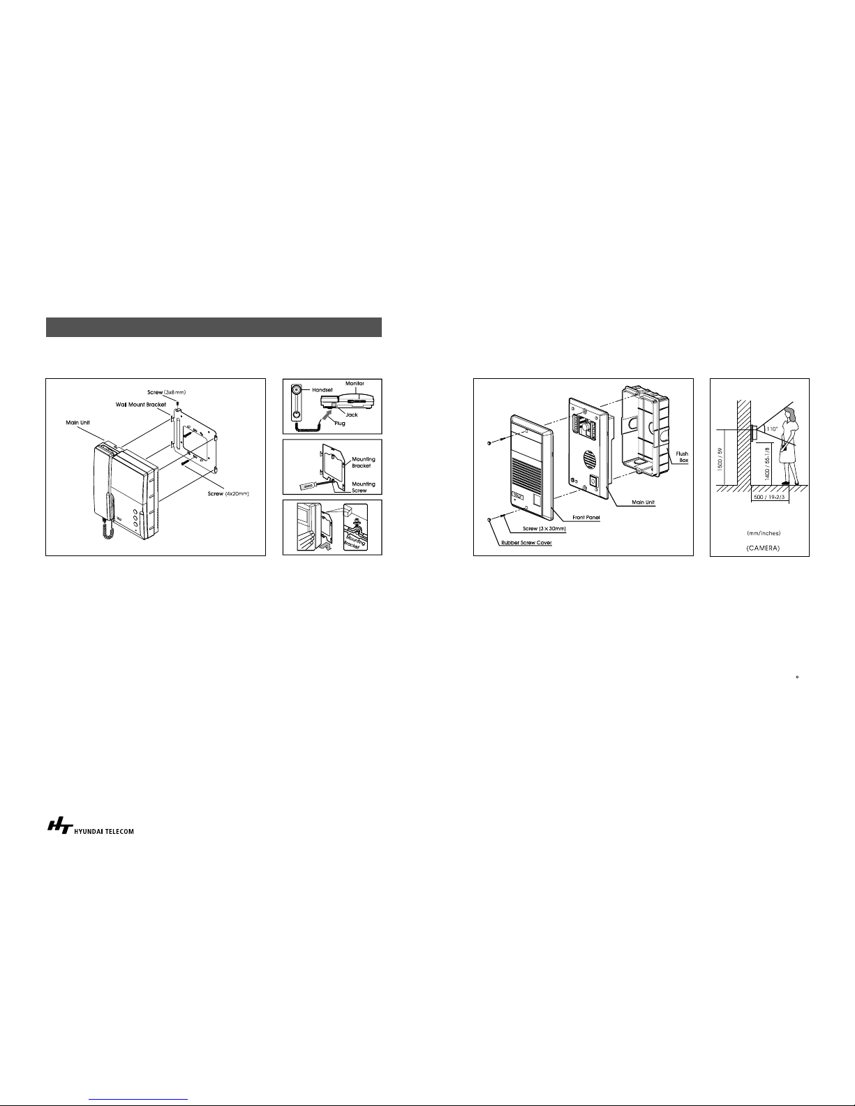
Installation
1. After determining the mounting locations for both the outside camera and
inside monitor, it is recommended to mount the camera and monitor to the
height of an average adult’s eye level from the ground (Approx. 1500mm / 59
inches).
2. At the selected monitors mounting location, attach the mounting bracket firmly
to the wall.
Drill a hole in the center area of the bracket just large enough for the electrical
wiring to pull through the hole. Connect the electrical wires from the camera
unit to the monitor-wiring terminal strip.
3. Connect the handset cord to the monitor unit.
4. Attach the wired monitor unit to the wall mounting bracket by setting the
monitor over the four bracket hook and slide it down, Insert the tiny machine
screw into the hole in the tab at the top of the bracket to hold the monitor in
place.
5. Plug the AC power cord into a standard household outlet.
6. Place the Power “On/Off” switch in the “On” position.
< Figure 2 > < Figure 3 >
INSTALLATION
Camera (HCB/HCC-300)
1. It is recommended to mount the flush box of the camera into the wall.
2. Remove the front panel from the main unit
3. Place the front panel on the main unit and attach them to the flush box with
two tamper proof screws provided.
Important Mounting Notes:
Do not install the monitor and camera units where they will be exposed to dirt,
direct sunlight (or other strong light), direct moisture, high temperature (over 40 C)
or high humidity conditions. Do not select an installation location subjected to
vibration or pounding.
Select a mounting location close to an AC outlet where it is easy to view the CRT
screen and operate the monitor.
< Figure 4 > < Figure 5 >
Page 8
HYUNDAI Video Door Phone | HA-201 / HAC-201 12|13
< Figure 7 >
< Figure 8 >
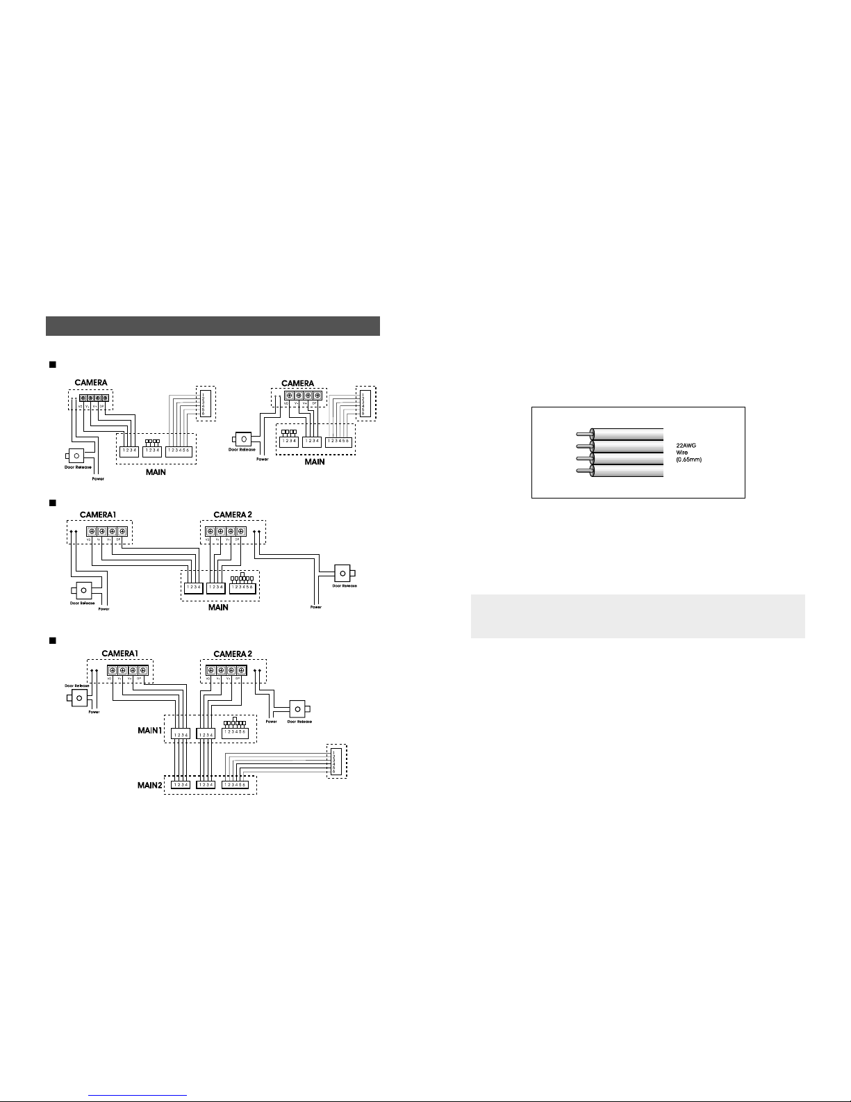
WIRING DIAGRAM
1 Monitor & 1 Camera & Image Memory
1 Monitor & 2 Cameras
2 Monitors & 2 Cameras & Image Memory
< Figure 6 >
CAMERA1 CAMERA2
HVM-200B/C
(Option)
HVM-200B/C
(Option)
CAMERA1 CAMERA2 HVM-200B/C
CAMERA1 CAMERA2
HVM-200B/C
(Option)
CAMERA1 CAMERA2
HVM-200B/C
CAMERA1 CAMERA2
HVM-200B/C
HVM-200B/C
HVM-200B/C
Wiring is not supplied with your Video Doorphone System. Use only AWG #22
wire(0.65mm) / TIV wire(0.80mm) and follow the appropriate wiring diagrams
exactly for optimum system performance and safety.
When planning the initial HA-201/HAC-201 System wiring installation, consider
future system expansion. The total wire length for a single camera and monitor
system (or any combination of additional cameras or monitors) must not exceed
50m/165feet total wiring for optimum performance.
< Figure 9 >
Note : 1) Connect 3,4 shut pin on the HVM-200B/C when you are not using image
memory
2) Use of color coded cable is recommended for proper wiring connection.
Page 9
HYUNDAI Video Door Phone | HA-201 / HAC-201 14|15
OPERATIONS
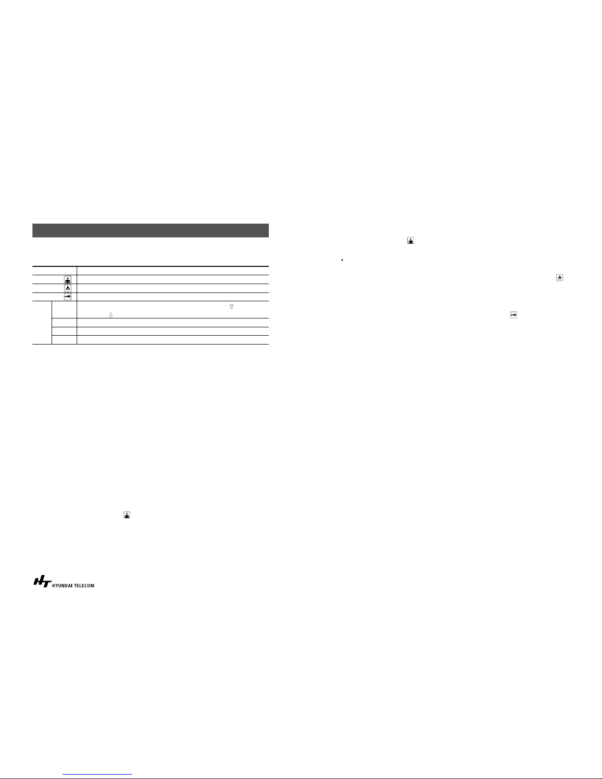
How to use buttons & adjustment on the unit
Communicating Function
1. A visitor presses the “Call” button on the outside camera unit.
The monitor will sound a “chime” tone two times to announce that a visitor is at
the door. (The picture on the monitor screen will appear)
2. Lift the handset to speak to the visitor.
3. Hang up the handset to terminate the conversation or if more than 30seconds
elapses after you lift the handset, the image on the monitor screen will
disappear.
4. If you install more than one monitor, each monitor will sound a “chime” tone two
times respectively after a visitor presses the “Call” button on the outside camera
unit. (The same picture on each monitor screen will appear). If you lift the
handset or master monitor for response, the image on the secondary monitor
will turn off after 30 seconds automatically.
5. The picture on the monitor screen will be replaced after another visitor presses
the “Call” button of the secondary camera while you speak to previous caller at
the master camera.
If you press “Monitor” button ( ) again, your call returns to the previous caller at
the master camera.
Monitoring Function
1. Press “Monitor” button ( ) to see the camera viewing area.
2. If you install more than two cameras, it will function in the following way:
Press “Monitor” button to see the master camera viewing area and then press
“Monitor” button again to see the secondary camera viewing area.
3. To turn off the monitor screen, hang up the handset or press “Volume” button ( )
Operating the Electric Door Release
1. After speaking with the visitor (and if you have installed an electronic door
locking system), you can press the “Door release” button( ) to electronically
unlock the door.
BUTTON DESCRIPTION
Monitor Turn on screen, switch cameras
Volume Volume adjustment, Turn off screen
Door Door release
Time Time Adjustment (Enter or Move: Use Time button, :Use Record
button, :Use Review button)
Rec
Record manually.
Review Review recorded pictures
Away Set or Reset “Absence” mode or quit the review
HVM-
200B/C
Page 10
HYUNDAI Video Door Phone | HA-201 / HAC-201 16|17
TROUBLE SHOOTING
If a problem persists after trying the remedies suggested below, contact your local
dealer or our technical support or sales department
Unit totally dead (Power Lamp OFF)
- The power cord is not properly inserted in the AC outlet, or the power is not
supplied.
- Check that the power ON/OFF switch is in the ON position.
Cannot gain enough volume when talking to other units
- Adjust volume with the button on the monitor (See page 6.)
Poor picture appears on the screen
- Make sure that the lens of outdoor camera is clean (Remove the transparent
tape attached on the outdoor camera after installation)
- After rain or when outside temperatures are very low, the camera lens may
temporarily fog over and cause a blurry image, but this is not malfunction and
normal operation will be restored when the moisture evaporates.
- The camera lens may be affected if it is in very bright direct sunlight from the sun
or artificial street or house light. When installing, if possible, choose a site that is
partially sheltered from direct light.
Can call and communicate, however, there is no audio signal
- Make sure the wiring between the monitor station and the camera station is
connected properly.
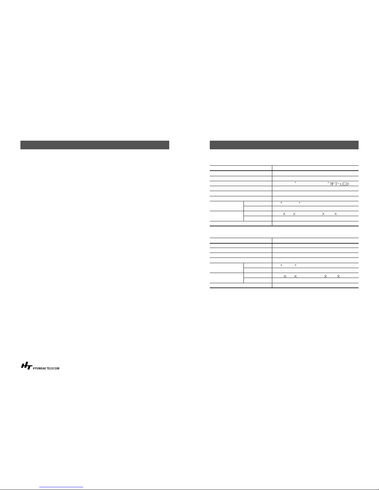
SPECIFICATIONS
Main unit Monitor
Flush Mount Camera (HCB-300/HCC-300)
Remark Specifications
Voltage Requirements DC 12V, 1.5A or 90~250V AC 50/60Hz(Smps)
Power Consumption Maximum 8.5W, Stand by 1.0W
Monitor Screen B&W Flat 4 Flat type C.R.T/4
Maximum Wiring Distance 50m/165 feet (22 AWG, 0.65mm 4wire)
Audio Communication Duplex handset
Extensions Monitor
Environment
Temperature -10 C to +40 C
Humidity Below 90% (relative)
Size
Dimension
188W 208H 60D(mm) / 7-2/5W 8-1/5H 2-1/3D(Inches)
Weight 1.3 kg / 2.86 Ibs
Installation Surface Mount Type
Remark Specifications
Power Source DC 12V (Supplied from Monitor)
Power Consumption DC 12V, 0.25A
Display Output 1Vp-p/75, Composite EIA / CCIR, PAL/NTSC
Illuminance 0.1 Lux(B/W)/3Lux(Color)
Environment
Temperature -10 C ~ 40 C
Humidity Below 90% (relative)
Size
Dimension
120W 184H 16D(mm) / 4-3/4W 7-1/4H 3/5D(Inches)
Weight 0.5kg / 1.10 Ibs
Installation Flush Mount Type
Page 11
HYUNDAI Video Door Phone | HA-201 / HAC-201 18|19
Warranty Conditions
Products are supplied with one(1) year return to base warranty
from the date of purchase. We will repair or replace the defective item with a new
or factory rebuilt replacement.
Condition
1. This warranty applies to the original purchaser only.
2. All warranty will be invalid if unauthorized repair or modification are made to the
unit or in any case of accident, misuse, damage caused by improper installation
and altered serial numbers.
3. The liability of is limited to the cost of repair/replacement of
the unit under warranty.
4. If you need a warranty service, you should send the product to our customer
service Dep’t or dealer office. The product in all cases must be accompanied
by the following items:
Your name, address, telephone number, the serial number, copy of your sales
receipt showing the purchase date.
The Model Number is on the box and front of the manual. The Serial Number is on
the bottom of the unit. Record the Model and Serial Numbers in the spaces
provided below. Refer to these numbers for warranty service.
Model No. Serial No.
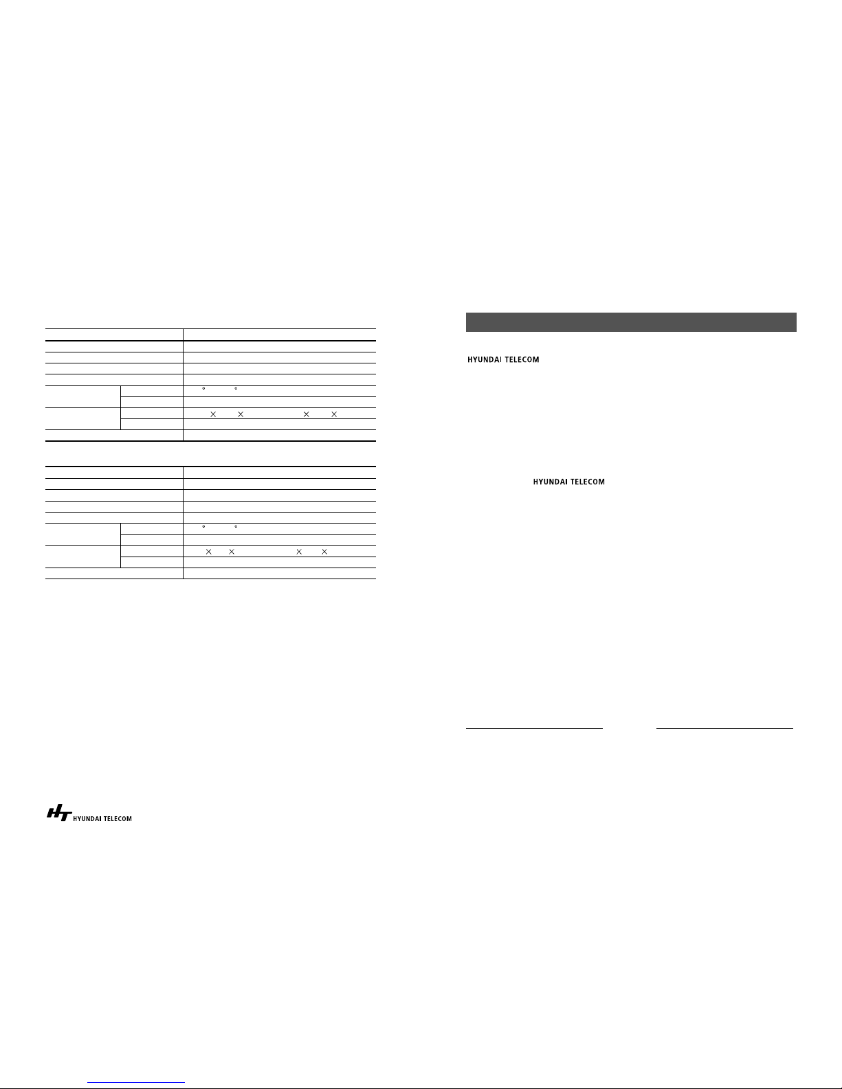
Flush Mount Camera (HCB-500/HCC-500)
Surface Mount Camera (HCB-150E/HCC-150E)
Remark Specifications
Power Source DC 12V (Supplied from Monitor)
Power Consumption DC 12V, 0.15A
Display Output 1Vp-p/75, Composite EIA / CCIR
Illuminance 0.1 Lux (B/W)
Environment
Temperature -10 C ~ 40 C
Humidity Below 90% (relative)
Size
Dimension
86W 117H 39D(mm) / 3.39W 4.61H 1.54D(Inches)
Weight 0.2kg / 0.44 Ibs
Installation Surface Mount Type
Remark Specification
Power Source DC 12V (supplied from Monitor)
Power Consumption DC 12V, 0.17A
Display Input 1Vp-p/75, Composite CCIR/EIA, PAL/NTSC
Minimum Illuminance 0.1 Lux (B/W) / 3 Lux(Color)
Environment
Temperature -10 C ~ 40 C
Humidity Below 90% (relative)
Size
Dimension
91.5W 132.5H 18D(mm) / 3-3/5W 5-1/5H 5/7D(Inches)
Weight 0.2kg / 0.44 Ibs
Installation Flush Mount Type
Page 12
Memo
 Loading...