

Page 1

QV FCA System Manual
2018.10.17
Writer : 박민호 책임
EE Laboratory DAS System Design Team
Page 2
1 page
EE연구소 DAS시스템설계팀
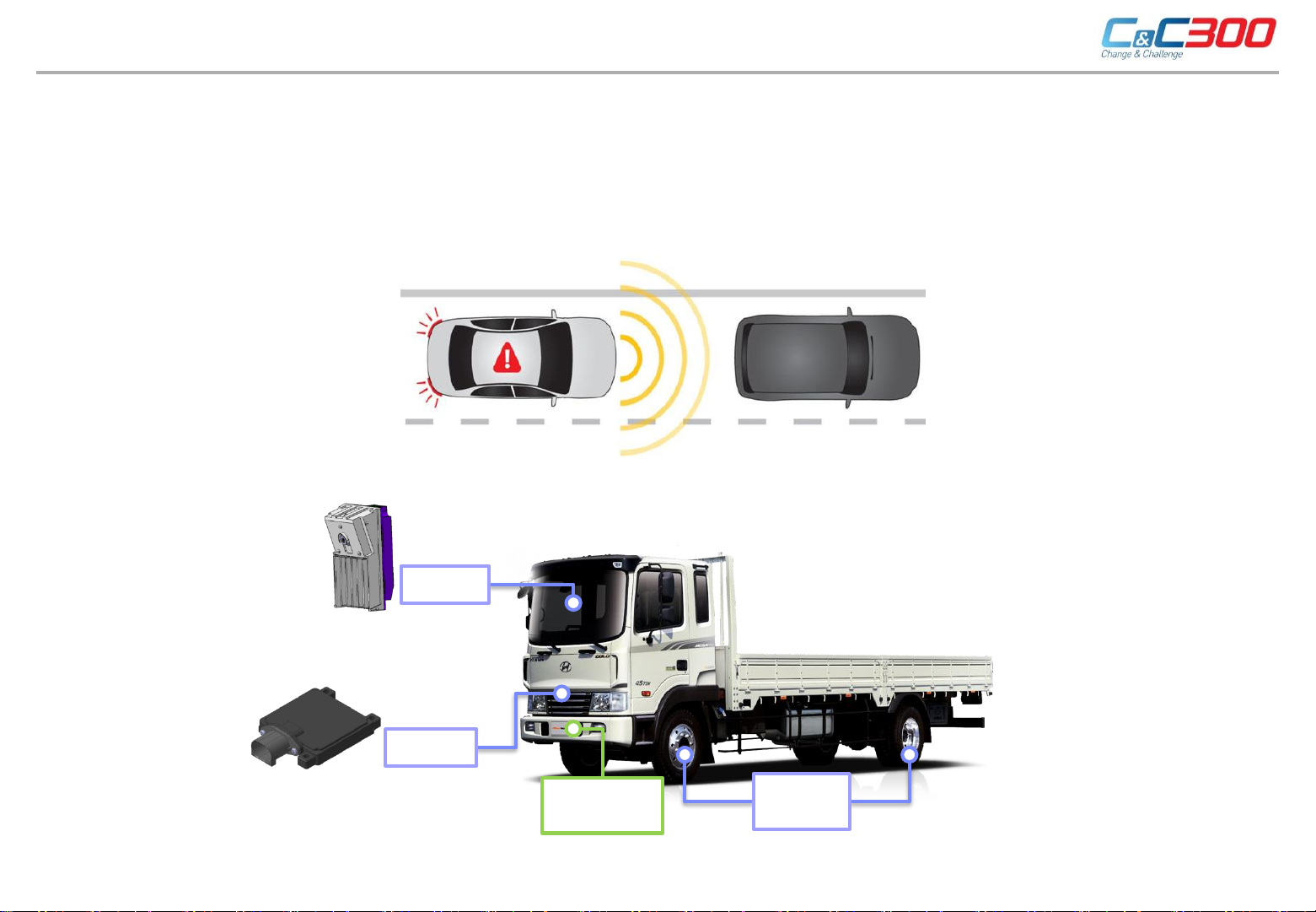
- Provide notifications and stop the vehicle when front sensor has recognized crash risk
ahead.
- Primary components: Sensor (MOBIS radar [MAR320], MOBIS camera [MAC110],
WABCO brake [EBS.ABS]
FCA (Forward Collision Avoidance Assist)
▣ FCA Outline
WABCO tire
pressure
VDC
independent
logic
(Extra ECU)
MOBIS
camera
MOBIS
radar
Page 3
2 page
EE연구소 DAS시스템설계팀
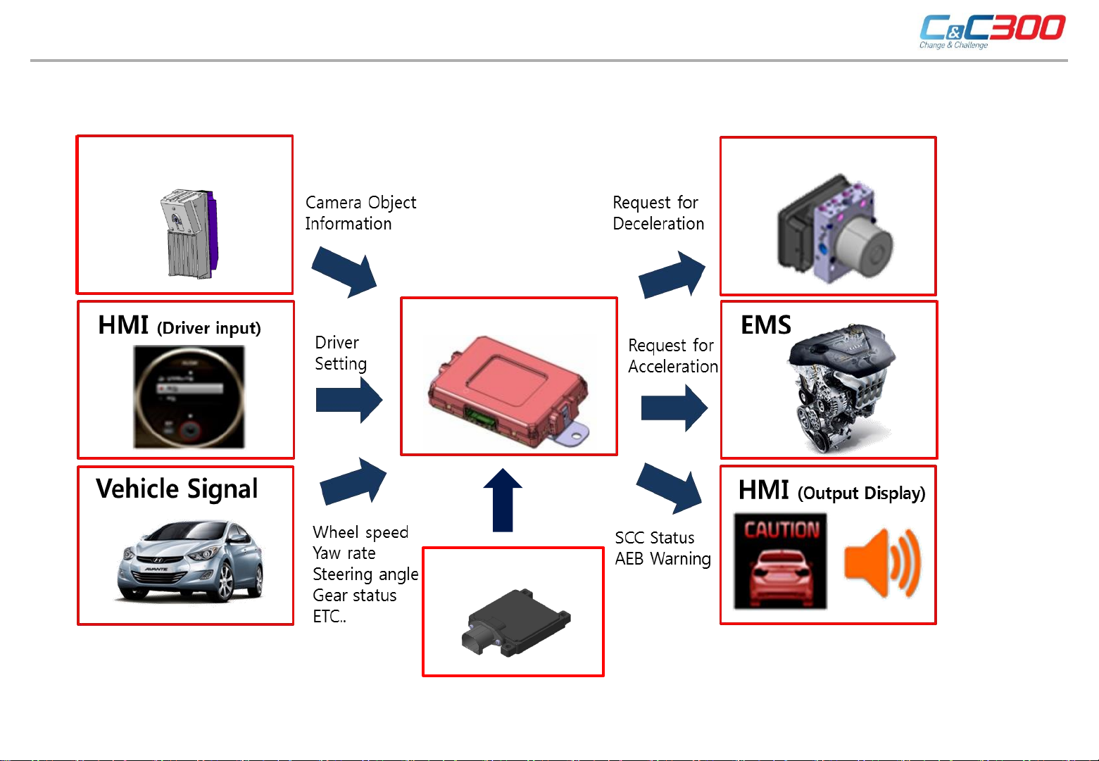
- FCA System Composition
▣ FCA System Composition
Extra ECU
MAC110
MAR320
EBS
Page 4

3 page
EE연구소 DAS시스템설계팀
- Features for each sensor
▣ FCA System Composition
Chassis CAN
FCA Target deceleration
Brake
VDC
Recognition
Vehicles
MOBIS camera
Traffic lane
MOBIS radar
Sensor Fusion
Radar/Camera
Sensor Fusion
FCA
Drive path
operation
Crash risk target
selection
Notice/ Stopping point
decision making
Target deceleration
calculation
Private CAN
Recognition
Objects
Stopping/Moving
targets Decision
FCA Controller (Extra ECU)
Drive path
operation
Diagnose/Fail safe
Diagnose
logic
Private CAN
Page 5

▣ FCA Operating Condition
Classification
Commercial Riding
Vehicle FCA Vehicle/Pedestrian/Bicycle FCA
Operating Speed (Moving Vehicle)
Partial braking(*0.35g) : 0~178km/h
Full-braking(0.6g) : 0~84km/h
Control Entry Speed Over 8km/h (FCA Default ON)
1stnotification(FCW) : Available to select alarm point via USM
HMI
Alarm Point
2ndnotification(Pre-braking) and 3rdnotification(Full-braking) : single point of view
Notice Type Alarm sound and dashboard warning message (Caution for front → Collision warning → Emergency Braking)
System OFF
When system off selected, light a same warn
Regulations for commercial vehicle have to follow the regulations in gray boxes
Stationary target Moving target
Steps
1step
(pre-
confirm)
347/2012
2step
(pre-
confirm)
347/2012
2step
(confirm)
2015/562
Target
Model
M3
N2 >8t
N3
M3
N2>8t
N3
N2≤8t
M2
st
1
Minimum 1 EA Minimum 2 EA Minimum 1 EA Minimum 2 EA
EBP start
Before 1.4sec
(sense of
hearing/touch)
EBP start
Before 1.4sec
(sense of
hearing/touch)
EBP start
*)
Before 0.8sec
(sense of
hearing/touch/sight)
Alarm Point
In 0.8sec before EBP
starts
(sense of
hearing/touch/sight)
In 0.8sec before EBP
starts
(sense of
hearing/touch/sight)
Before EBP starts
(sense of
hearing/touch/sight)
amount
nd
2
of
decelera
tion
Over10
km/h
Over20
km/h
Over10
km/h
Partial braking(0.2~0.4g) : 0~180km/h
Full-braking(0.8~1.0g) : 0~80km/h
ing light * asun sdeysr teminv brokestigatioen li ngh(t0.35g0.3g or less)
st
1
1.4sec before
EBP starts
(sense of
hearing/touch
1.4sec before
EBP starts(sense
of hearing/touch
0.8sec before
EBP starts(sense
of hearing/touch
Alarm Point
2
In 0.8sec before EBP
starts (sense of
hearing/touch/sight)
0.8sec before EBP
starts(sense of
hearing/touch/sight)
Before EBP starts
(sense of
hearing/touch/sight)
nd
amount
of
deceler
ation
collisio
n
prevent
ion
collisio
n
prevent
ion
collisio
n
prevent
ion
Speed of front
vehicle
32±2km/h
12±2km/h
67±2km/h
Row
1
2
EE연구소 DAS시스템설계팀
4 page
Page 6

5 page
EE연구소 DAS시스템설계팀
Classification
Operating Specification
VehicleAEB
Cancel Control
Condition
①
Driver’s normal cancelation
- When AEBS OFF is selected
- When ABS/VDC switch first gear is selected for OFF
②
Driver’s movement cancelation
- When FCA operating speed is under 8ph
- When FCA operating speed is above 178kph
- In condition of sudden steering control (Over SAS 172 deg/sec and 115 deg)
- When gear is P or R
- When gas pedal is above 80% or driver Kick-down it
- When road curve radius is under 50m
③
System error cancelation
- When radar/camera is broken-down
- When related other module or CAN telecommunication is broken-down
Critical
Situation
①
Abiotic Factors
- Bad weather conditions
- 역광, 반사광으로 카메라 인식 불가시
When camera is not operated because of
counter light or reflected light
- Contamination of camera or radar
②
Camera or radar detection limit
- Vehicle or pedestrian suddenly cut in front
- If width of front object is narrow
- If taillight of front vehicle is asymmetry or not operated at night
- oncoming vehicles or oncoming vehicles with backward state
▣ FCA Cancel Control Condition/Critical Situation
Page 7

6 page
EE연구소 DAS시스템설계팀
구 분 Warning Messages
Dashboard
Imeages
Explanation Warning from first step to three step warning message + OFF
8Hz
recurring
sound
8Hz
recurring
sound
Continual
sound
▣ Cluster Operation while FCA is Operating
Emergency Braking
OFF
Caution for collision Emergency Braking
Caution for front
Page 8

7 page
EE연구소 DAS시스템설계팀
▣ Radar Specification
70
73
97)
91
MAR320(Independent MRR)
System Specification Performance
Normal Voltage 12V
Using Frequency Range 76 ~ 77GHz
Size(mm) 73 x 70 x 15 (TBD)
Weight <150g
Feature High Speed FMCW
Mode If power is connected, antenna is eradiated as single mode
Extra
Controller
Front Radar
reverse gear
AEBS switch
Page 9

8 page
EE연구소 DAS시스템설계팀
▣ Extra ECU Specification
○ Purpose: communication (CAN, CAN-FD, LIN) based controller for controlled calculation.
- FE RSPA (’18. 1) Controller based HW design for suitability of commercial product (24V power available)
- RADAR product power supply feature added
QV FCA ECU
<QV FCA Extra ECU Exterior>
<QV FCA Extra ECU Exterior>
Divisions Items Specifications Note
ECU
Rated Voltage
DC 24 V±0.4V
Operating DC 16V ~ 32V IGN Power usage operation
Operating Temperatures -40℃ ~ 85℃
PCB Size [mm]
110 × 76 × 1.6
Material: FR-4(6L), Plating: with gold
ECU Size [mm]
129.6 × 86 × 25
PP-(CF+CB)20 -> TBD
MCU
Core 32bit Dual-core
# of Cores 3 Core Lockstep-core + Single-core
Operating Frequency 200Mhz
COM
HS-CAN/CAN-FD
J1939
3 Ch. (reserve 1Ch.)
CAN-FD communication speed: Max.
2Mbps
Common use CAN J1939 support
LIN (reserve 4 Ch. ) LIN 2.1 support
SPI 2 Ch. SPI (PMIC, EEPROM)
Memory EEPROM 64Kbit with SPI
In put/Out put
INDI. AEBS SW Max. 30mA Switch LED PWM output
INDI. OUT_LED2 Max. 30mA Switch LED PWM output (reserve)
AEBS SW IN Open/Short type AEBS Switch signal input
Reverse SW IN 24V/Open type Reverse information signal input
SW IN_3 Open/Short type Switch signal input – 3 (reserve)
Radar Sensor Power
Max. 1.5A
Dual-ch. HS Power IC
External sensor 12V power supply
Exterior Sensor
Power(reserve)
Page 10

Information
RF Exposure Statement (MPE)
The antenna(s) must be installed such that a minimum separation distance of at least 20 cm is maintained between the radiator (antenna)
and all persons at all times. This device must not be co-located or operating in conjunction with any other antenna or transmitter.
Contact Address: HYUNDAI MOBIS Co., Ltd. 203, Teheran-ro, Gangnam-gu, Seoul, 135-977, Korea
EE연구소 DAS시스템설계팀
9 page
 Loading...