

Hyundai Heavy Industries ACONIS 1000 User Manual

User's Manual
System Description
ACONIS-1000
System
Description
HYUNDAI
ACONIS
Hyundai Heavy Industries Co., Ltd,
Page.
1
System Description
Table
of
Contents
<Contents>
1. System Description .................................................................................................................
..··..
1.1. Introduction ....................................................................... ·
1.1.1. Features .......................................................................................................................................... 4
1.1.2. Installation ........................................................................... · .... ·
1.1.3. Man-Machine Interface ................................................................... ···· ..·
1.1.4. Communication Bus System ............................................................................................
Unmanned
1.1.5.
1.1.6. System Structure .....................................................................
1.2. Process Control Station ............................................................................................ · .......... ·
1.2.1. Process
1.2.2. Interface unit .................................................................................................................................. 8
1.2.3. Structure of Process Control Station ....................................................................................... 8
1.3. Server Control Station ........................................................................................................................ 9
Monitoring .......................................................................... ···· .... · .... ····· ..····..·..· .... · ..·4
unit
.....................................................................
· .... ······· .... · ..···
..··..·..
···
.... ······ ..···..·····..···..··..·······..····
···..·..·..·····..··
.... ··· ..·· .. ·..
····..· ..........
.. ··.. ··....
......
···..····..·..·..··..·..
···
.. ·..
············3
· .... ···· ..········..··3
·· ..
· ....
··..·..
· .... · ....
·· ..·····..·..········
··
....··.... ····7
·····
..
.... ·
······8
..
..
···6
··4
··4
..
4
Hardware
1.3.1.
1.4. Miniature Remote Terminal Unit
1.4.1.
Hardware
1.5. Operator Control Stations .....................................................................·····
1.5.1. Video Client .................................................................................
1.5.1.].
15.1.2.
1.5.2. Alarm Server ..............................................................................................· .... · ..· ........ · ..·
1.5.2.1.
1.5.2.2. Alarm Printing ........................................................................ ····· ..........
1.5.2.3. Log Printing .........................................................................
1.5.2.4. EAS Management ............................................................... ········ ..·..··········..·····..·········
1.5.3. Operator Control Station's Communication ....
1.6. Communication Interface Gateway .... ·
1..6.1.
Hardware
Display Structure of Video Client ...... · ..· .......... ···· ........................ · ...... · ...... ··............ · ...... 13
Hardware
l1ardware structure ...................................................................
Structure
Structure .............................................................................··..
of
Server control Station ....··..·..
and
Real-Time Control Station ·...... · ..·
Structure
Structure of Alarm Server ·.... · ..···..· ........ ··......··..·..·.... ·..·....
of
Video Client ··.... · ..· .... ···
· ........ ·
....·..·..
··..··..·..·..·· ..··
.. ·· .. ··
.... · ..···
·· .. ·..·..
··..· ............ · ...... · ..·
....··....·....·....·....··..........··..
···..·
.......... · ...... · .... ···· ...... · ..·..·12
....
.. ·· ..···· .... ··············· ..··········
· .... · ..···
................ · ...... ·
....
······.... · .... ····· .......... ··..
..
·····..···..········..··..····..·..·12
...... ·
· ...................... ·
·· .. ··
······ ........ ······· ..· .... ······
· ...... · ......
· ...... · ...... · .... · ..·
.. ··
....··..·..··..
.. ·..
· ...... ·14
....
···..·····
....
···
....
··..
· ........ · ........ ·17
· ......
..
10
..
11
·11
··12
..
·14
..
14
..
·15
···16
·18
..
18
HYUNDAI
ACONIS
Page. 2

User's
Manual
System Description
------
....
-----~------------------------------
1. System Description
The ACONI5-1000 System is a total control
multi-functional
system for ships
technology
system offers a
large variety of different
highly significant.
vessels, container ships, reefers
1.1 Introduction
The ACONI5-1000 System
computer
microprocessor technology. The tasks
among
• Process control station : performs interface
•
• Server control station : control the communication
capacity
sub-stations.
The
sub-stations
automatic regulation
Operator
and
transverse
operator
connected to communication bus.
in
uniform
high
alarm
and
monitoring,
offshore vessels
hardware
degree of reliability
types
It
is
adaptable
which
are
divided
control
station:
communication
control stations
is fully
and
data
based
concept. With its
and
and
sizes of ships
for all types
and
other
special
has a modular
distributed
in
into three
control.
performs
control
between buses
and
interface gateway(if GW)
.....
---
system
acquisition, control
on
flexibility,
where
of
purpose
and
to all control
which
interfaces
system
fully distributed microprocessor
modular
ships, e.g.
system
which
makes
efficiency
bulk
and
vessels.
flexible
system
room
stations,
the ACONI5-1000 System
groups:
with
process, signal manipulation,
and
supervision.
and
between
manage
the
all
and
.....
----
with
other
and
other
structure;
it
suitable for
the
reliability are
carriers, cruise
structure,
are
other
database
other
with
by
use
of
a
distributed
stations
over
systems
HYllNDAI
The controlling
equipped
with
module
memory
(General Control Module) is
Communication
through a dual
updating
cable
risk
interference
time
as
well as coaxial cable. The
of
total break
or a broken
between
bus-system
of
less
than
down
of
a sub-station comprises
device
and
used
sub-stations are carried
at
the
1 second. The communication
of the
bus.
Process control stations are connected
bus
control
system,
communication
stations
the
channel
of
operator
64
operator
can
be connected
control stations is connected
of
the serial communication module. This
control station
module
through
and
its
on a bus
and
the first
stand-by
The ACONIS-1000 System is
requirements for a periodically
ACONIS
unmanned
one
communication
module.
for this controlling module.
out
in
high
speed
of
375,000 bps, giving the system
media
bus
system of the ACONIS-l000 eliminates the
system
one
designed
caused
with
synchronous
module. A
system. The
to
alarm
station
to
engine
by
earth
failure, electro-magnetic
one
another
interface channel of the
maximum
operator
the
bus
with
meet
room
control
second
system
one
the classification of society's
operation.
32bit microprocessor
The
abbreviation
a digital serial
uses
twisted
by a
duplexed
of
32 process control
bus
system
synchronous
connects a
GCM
mode
process
from
interface
maximum
another.
The
design
Page.
an
pair
3
lffer~f
Manual
System Description
conforms
addition, the ACONI5-1000 System
1.1.1 Features
The ACONI5-1000
microprocessor-based
basic
alarm
operation
The ACONIS-l000 System
the DCS (Distributed Control System),
microprocessor-based stations
design. The
local control stations
supervisory
can
keep
supervisory
space
in
system,
1.1.2 Installation
Each ACONI5-1000 station
local installation. Each
can
be
to
all rules
and
of
the
machinery, especially
structure
control station's
the
entire control process of
and
regulations,
alarm
system
designed
and
has
high
monitoring
to
provide
all types of
reliability
and
status information they require to
when
unmanned.
has
the
has
of the DCS
can
operate
break-down
advantage
and
Flash Disk
has
merit, unlike
their
could
the
own
that its
each auxiliary storage device
or
ROM (Read
local
occur, the sequential control
system
module
in
their systems.
control system is a
the
ship's
maintain
structure
the
Central Control System, all
work
from
stopping
control station's break-down. The auxiliary storage device is a
which
and
installed
executable
disk storage
in
one
cabinet.
can
unit
code
be
can
and
data
can
be
used
for general purposes.
has
the
potential of
be
installed locally
stored
and
in
the microprocessor-based
both
central installation
also all the
are
approved.
officers
a safe
is designed
Only
Memory)-based
control.
because of
units
with
and
efficient
Though
memory
together
In
all
the
by
in
the
works
the
and
a
1.1.3 Man-Machine Interface
Operator
keyboard
provides
each display
directly
handled
control stations
and
tracker-ball.
standard
and
including
by
customized
the
the
tracker balL
1.1.4 Communication Bus System
The communication
1.1.5
structure
can
devices
in
the
and
Server control station is basically a
and
by
providing
Unmanned
and
machinery watch
in
which
work
in
and
stations. The Server control station is
bus
system
supervises
the
reserve link station. The reserve Server control station
the
lower
case
of a communication
which
and
controls
hot
back-up
Monitoring
All
monitoring
in
the
Engine Control Room (ECR). Sufficient facilities
and
on
the bridge,
alarm
provide
Graphic
full colored graphic displays, functional
user
interface
mimics
through
graphic interface button,
bus
system
bus
of ACONIS-l000
system
and
the
line fault
connects the
communication
of
data
facilities are
and
lower
dual
station consisting
base
in
the
main
provided
a watch-caning
bus
load
in
the man-machine interface
colored graphic display,
the
functional
has
upper
and
bus
system
break-down
the
communication
system
in
and
the ACONIS-l000 system. The
of
keyboard
a basic
dual
are
of
communication
master
the
upper
the
main
has
a fault tolerance
separate,
Server control station.
both
in
the machinery space
are
also
provided
subsystem
which
enables
and
for
can
be
network
and
station
bus
system
link station
for
I1YUNDAI
ACONIS
Page.
4

User',,)
Manual
System Description
engineers to be automatically called to the ECR
duty
in
their quarters. Thus, both the machinery
unmanned
while machinery
watch
is carried
out
when
they are away
and
on
the bridge.
the ECR
on
may
safely be left
watch-call
HYUNDAI
ACONIS
Page. 5
User's Manual
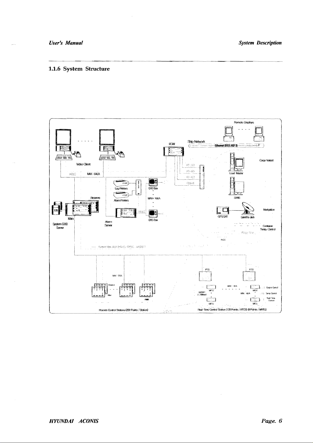
1.1.6
System
Structure
System Description
rD."
····101
......
.
~ LJ
~J
~.··
..
~·-.e
..
..
~~
-~~
..
___ l
CTIJ
t..b".
l~>
·."tb~~~,~~n
fl6a..
HYUNDAI ACONIS
Page.
6
User's
Manual
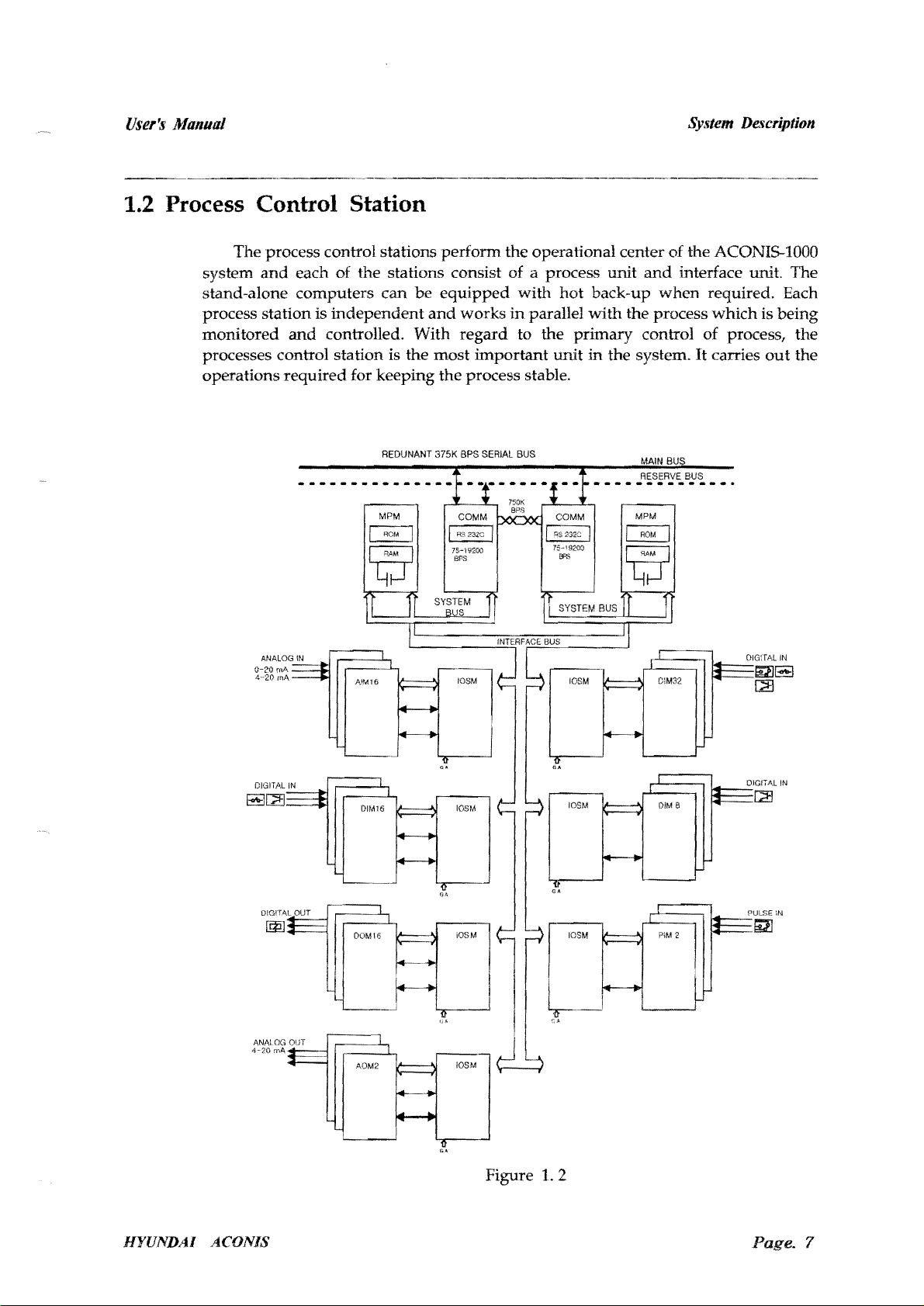
1.2 Process Control Station
System
De,~cription
The process control stations
system
stand-alone
process station is
monitored
and
each of the stations consist of a process unit
computers
can
be
independent
and
controlled. With
processes control station is the
operations
0-20
4--20
rnA
inA
required
for keeping
REDUNANT
perform
equipped
and
works
regard
most
important
the
process stable.
375K
BPS
SERIAL
the operational center
and
with
hot
back-up
in
parallel
to
BUS
the
unit
with
the process
primary
in
------------.-
control of process, the
the system. It carries
MAIN
RESERVE
MPM
of
the ACONIS-1000
interface unit. The
when
required. Each
which
is
out
BUS
BUS
OIG:TAL
~~
[2J
being
the
IN
DIGITAL
IN
~G!l
DOM16
AOM2
Figure
I
'"'"
~.-
1.2
PUL.SE IN
till
HfUNDAI
ACONIS
Page.
7
User's
Manual
System Description
1.2.1 Process
unit
Each process
monitoring, automatic control
sequential controls,
different arithmetical operations, etc.
process control station receives
command
The control
command,
the
number
collects
required,
1.2.2 Interface
The interface units connect
system. They also
protection.
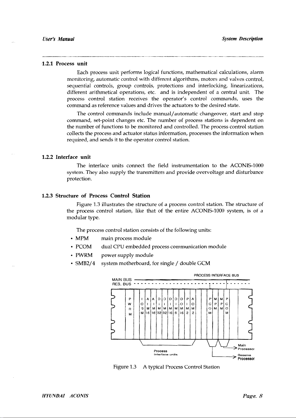
1.2.3 Structure
Figure 1.3 illustrates
the
process control station, like that
modular
unit
performs logical functions, mathematical calculations,
group
as
reference values
commands
set-point changes etc. The
of functions to
the
process
and
sends
and
actuator
it
to
the operator control station.
unit
supply
of
Process Control
the
type.
with
different algorithms, motors
controls, protections
and
the
operator's
and
drives the actuators
include
manualj
number
be
monitored
status
the
the transmitters
and
information, processes the information
field instrumentation to
and
Station
structure
of a process control station. The structure of
of
the entire ACONIS-1000 system, is
alarm
and
valves controL
and
interlocking, linearizations,
is
independent
of a central unit. The
control commands, uses the
to
the desired state.
automatic changeover,
of
process stations is
start
and
dependent
stop
controlled. The process control station
when
the
ACONIS-IOOO
provide
overvoltage
and
disturbance
of
on
a
The process control station consists of
• MPM
• PCOM
• PWRM
•
5MB2/4
main
dual
CPU
power
process
supply
module
embedded
module
system motherboard, for single / double
MAIN BUS
RES.
BUS
- • - - - - - - - -
I
P
W
RI
I
I M I
~
0
S
!
M
AlA
~I~
16116132
~
Figure 1.3 A typical Process Control Station
the
following units:
process communication
GeM
PROCESS INTERFACE BUS
••
- -
••••
-
••
D
D
I
~
M
32
Process
Interface
D
M
16
I
units
D D
11
M M
8
A
P
0
I
0
M
M
16
2
2
!
I
module
! . - - -
P M
C P
o M
1M
yv
1-
M P
P C
M
~I
-7'
. - . - - .
Main
Process
Reserve
~
Prooessor
or
HYUNDAI ACONIS
Page.
8
User's
Manual
The following types of interface units can be used at the process
control stations;
•
105M
input-output
multiplexers for the process interface units
• AIM16
• DIM32
• DIM8
analog
digital
digital
input
input
input
for monitoring of auxiliary engine
• DIM16
• DOM16
• PIM2
• AOM2
• DOD
digital
digital
pulse
analog
demand
input
output
input
module for a signal pulse frequency
output
on
display
1.3 Server control Station
scanning
module
module
module
module
module
module
module
for 16 analog signals
for
32
contacts
for 8 contacts,
e.
g. 3 line
shutdown
for 16 contacts
for 16 contacts
for 2 analog
output
input
signals
System Description
with
33k
.Q
The Server control station controls
between the stations connected to the process control
and
supervises the data communication
bus
and
operator control bus.
Data transfer at the Server control station is serial. The HDLC protocol is
communications.
The Server control station
ACONIS-l000 system
and
control stations, has the features to get
information for the process control station,
function.
new
log information,
In
addition, the database is installed inside, all
event
in accordance to
trend
information,
manages
functions as
I/O
data
status,
alarm
the communication
an
information server for the operator
I/O
data
in
the lower
and
has the task
the
and
managing information
display list
and
bus
system
part
of
work
such as creating a
inhibit display list,
system clock are carried out.
dual
The Server control station is a
tolerance. The operator control
dual
network
and
each
bus
bus
is isolated
Therefore if a break-down occurs
bus
Because a
it
problem,
station.
is automatically replaced
During
replacement never occurs. In
dependent
of the Server control station,
independent
connected to
reserve
bus
process control
system is designed
this process, delay
main/reserve
of the Server control station. Therefore, the operator control
the
main
bus
system
system in the reserve Server control station. Irrespective
bus
is simultaneously connected to the
station designed
and
the process control
and
in
one system, it
by
the
by
the reserve
and
loss of
and
in
the
main
connected to the Server control station.
won't
dual
network,
data
substitution, the operator control
the process control station
Server control station,
by
the
structure of fault
bus
are designed
effect the other systems.
when
one
network
network
main/
in the Server control
in
the
network
reserve system.
used
in
the
in
the
and
alarm
synchronous
in
system,
and
a
by
the
has
a
requiring
bus
is
bus
is
bus
is
and
to the
of
this, the
HYUNDAI
The most
in
case of a
ACONIS
important
main/reserve
feature is
the
substitution
consistency of each database installed inside
in
the Server control station. This is because
Page. 9
User's Manual
the reserve Server control station must hot back-up the database in the main
Server control station under the suspend mode. The main Server control station in
the beginning of operating back-up the data base in the reserve Server control
station
when completed, the back-up communication right is given from the reserve
Server control station.
stations,
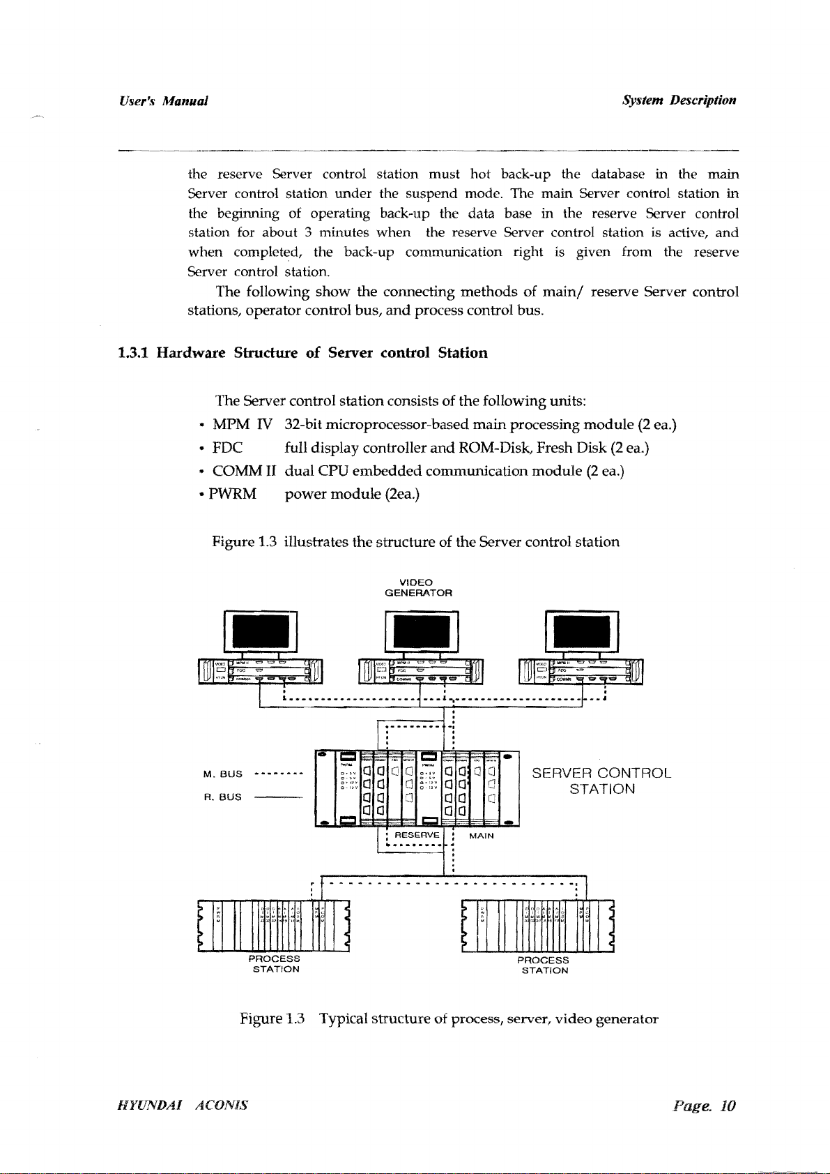
1.3.1
Hardware
System Description
.--~.-----------.---~--------~
for about 3 minutes when the reserve Server control station is active, and
The following
operator
Structure
The
Server control
•
MPM
• FDC full
COMM
•
• PWRM
IV 32-bit microprocessor-based
II
show
control
of
display
dual
CPU
power
the connecting
bus,
and
process control bus.
methods
Server control Station
station
module
consists
controller
embedded
(2ea.)
of
the
main
and
ROM-Disk, Fresh Disk
communication
of
main/
following units:
processing
module
reserve Server control
module
(2
(2
ea.)
(2
ea.)
ea.)
Figure 1.3 illustrates
. .
1
•••
_.
_________ • _____
M.
BUS
••••••••
R.
BUS
~
" J ' , f
the
structure
of
VIDEO
GENERATOR
_
._,~-_-._.---_-_----.---
the
Server control
(]
(]
C
C
MAIN
SERVER
'0
I,j......
loOU
.'
3>
~,
...
station
CONTROL
STATION
HYUNDAI
Figure
ACONIS
PROCESS PROCESS
STATION STATION
1.3 Typical
structure
of process, server,
video
generator
Page.
10
User's Manual
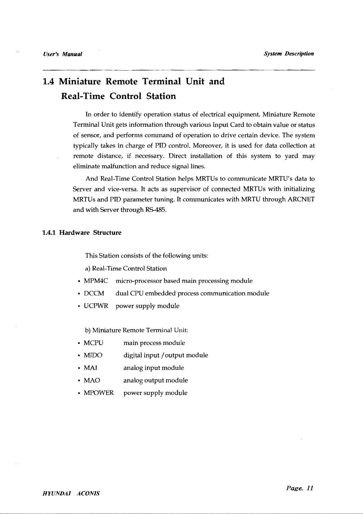
1.4 Miniature Remote Terminal Unit and
Real-Time Control Station
In
order
to identify operation status of electrical equipment, Miniature Remote
Terminal Unit gets information
and
of sensor,
typically takes
remote distance, if necessary. Direct installation of this system to
eliminate malfunction
And
Server
MRTUs
and
and
and
with
performs
in
charge of PID control. Moreover,
Real-Time Control Station helps MRTUs to communicate MRTU's data to
vice-versa.
PID parameter tuning.
Server
through
command
and
It
RS-48S.
through
reduce signal lines.
acts as supervisor of connected MRTUs
various
of operation to drive certain device. The system
It
communicates
Input
Card
it
is
with
System Description
to obtain value
used
for data collection at
with
MRTU
through
or
status
yard
may
initializing
ARCNET
1.4.1
Hardware
This Station consists of the following units:
a) Real-Time Control Station
• MPM4C micro-processor based
• DCCM
• UCPWR
b) Miniature Remote Terminal Unit:
• MCPU
• MIDO
• MAl
• MAO
• MPOWER
Structure
dual
power
CPU
supply
main
process
digital
analog
analog
power
embedded
module
input / output
input
output
supply
process communication
module
module
module
module
main
module
processing
module
module
HYUNDAI ACONIS
Page.
11
User~f;
Manual
System Description
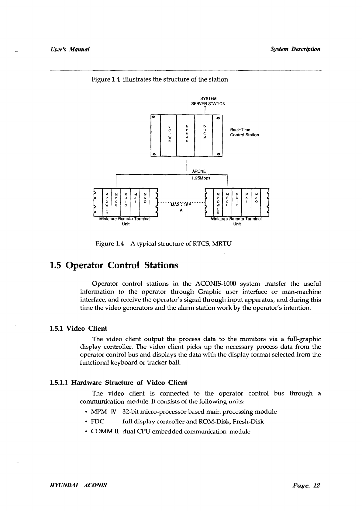
Figure 1.4 illustrates
the
0
0
structure
M
V
P
C
p
M
4
w
C
R
of
the
SYSTEM
SERVER
i
0
C
C
M
ARCNET
1.2SMbps
station
STATION
0
Real-Time
Control Station
0
t I
M
M
p
P
0
C
U
W
E
R
. .
Mlnuature Remote TermInal MIniature Remote Terminal
Figure 1.4 A typical
M
D
I
0
Unit
M
M
A
A
I
0
,,'
--MA5(:'i6E'"
A
structure
ofRTCS, MRTU
..
>
>
>
>
M
M
P
0
w
E
R
..
M
P
D
c
I
u
0
Unit
C
M
M
A
A
I
C
0
~
(
1.5 Operator Control Stations
Operator
information
interface,
time
the
1.5.1 Video
Oient
The
display controller. The
operator control
functional
1.5.1.1 Hardware Structure of Video Client
The
communication module.
• MPM N 32-bit micro-processor based
• FDC full display controller
•
COMM
control stations
to
the
operator
and
receive
the
video generators
video
client
output
video
bus
and
keyboard
video
II
or
tracker ball.
client is connected to
dual
CPU
in
through
operator's
and
the
alarm
the
process
client picks
displays the
It
consists
of
embedded
the
signal
communication module
ACONIS-1000 system transfer
Graphic user interface
through
station
data
up
data
with
the
the
follOwing units:
main
and
ROM-Disk, Fresh-Disk
input
apparatus,
work
by
the
operator's intention.
to
the
monitors
the
necessary process
the
display format selected from
operator control
processing
module
the
or
man-machine
and
during
via
a full-graphic
data
bus
through
useful
from
this
the
the
a
HYUNDAI
ACONIS
Page,
12

User's
Manual
System
Description
Figure 1.5
shows
~
=
t::::=:Jc::::::::J~C::::::==c::::::::J
t:::::::::::lc::::::::Jt:::::::::::lc::::::==c::::::::J
the structure of
20" COLOR CRT
t:::::::::::l
[::=J
c::::::::J
===:J
o
R.BUS
M.BUS
I:=:J
I:=:J
c::::::=
I:=:J
ACONIS
GJJ~~TOR
ON
OFF
~
HYUNOAI
the
video
generator
=
=
TRACK-BALL
Fo
e
~
COMMU
KEYBOARD
~
o
Figure 1.5 The Structure of Video Generator
1.5.1.2 Display Structure
The basic
arrangement
• Status Display
•
Group
•
Alarm
Display
Display
• Inhibit Display
•
Pow
er Control Display (optional)
• Graphic Display (optional)
• Trend Display
• Log Display
•
Custom
•
Help
The text
in
the condition of
Display
Display
and
are as follows :
GREEN
RED
RED BLINKING Unacknowledged
CYAN Interlock Status
PURPLE
of
Video Client
of the video client display
the graphic symbols are
the
channel of
Normal
the
display of the video client. The color
Status
Acknowledged
Suppressed Status
supplied
Alarm
Status
Alarm
on
screen are as follows
through
the
relevant color
Status
data
data
used
HYUNDAI
ACONIS
Page. 13

User's Manual
1.5.2
Alarm
System Description
Server
1.5.2.1
The alarm server
ACONIS-1000 system
output
and
Hardware
the normal log information
to
manage
Structure
EAS (Extended
has
the capability to
in
chronological
Alarm
of Alarm Server
The alarm server consists of the follOwing units:
• MPM IV 32-bit micro-processor based m
• FDC
•
COMMll
•
105M
• DIM16
• DOM16
full display controller
dual
CPU
embedded
input-output
16bit
16 digital
16 digital
EC
R
input
output module (2
scanning
module
output
order
through
and
the daily log information by the log printer,
the
status
events from the
the alarm printer, to timely
System) .
ain
processing modul
and
ROM-Disk, Fresh-Disk
communication
module
e
module
ea.)
W! H
RS485
COMMUNICATION
ENGINEER
1.5.2.2
=
RBUS
M.BUS
Alarm
Printin
The alarm
in
chronological order. The events are the al
inter-lock event. The color
vent
and
e
g
printing
normal
event
is allegedly
prints
are
respective!.
ALARM
PRINTER
A
LARM SEVE
=
<=>
wanted
red,
to
blue and block for alarm event, inter-lock
prin
arm
R
t o
ut
event,
the
events from
the
normal
LOG
PRINTER
event, and the
the
system
HYVNDAl
ACONIS
P
age.
14

User's Manual
The
(H
\'UND.A.I
98/03/15
3Wo.:-v'
98/W
98/0311<;
9
B/03!15
SalO3/
SatWl5
9!Y03!15
98/(13/
SW03/15
98/G3/t5
813!()3/t
following is
c
~
.
_ :
••
ACO
I~18
.ALARM
22:36~
3S
22'36:j5
15
2~:3~:
15
15
15
5
J5
22:36:
3'J
2236:35
Z?:36:35
2Z
~G:
35
:2.36.35
22:36'
3'"
::'Z.36:
35
22:36:35
22:36:35
an
H
YUNDAI AeO
__
""":::"""
8Y:3TEMJ·.·········.·
1111
MfE
1112
MiE
11 13,11i
E
1115
MIE
1116
WRC.IJG
II~<I
WE
1
125
WE
I
IZE>
MIE
1131
!vi
lE
II
·2
MiE
11
41
CPP
1142
CPP
example of a
NIS SYSTeM MARINE & OFFSHORE
~~
~~L~~~M!=Y:E..
SHI
'DOW~I
SLOVVDQWf';
\,IVnODI'V.I!.RD
SAFEW
V\I.AY
SIIFET'"
EXH
VV
C('NTSYS
tJ':,
1 AU'
t
10
J
ALJ,~
RE"" :nc c
leu
F",n,fR
print
..
·-·--·-·-··-·-·····-
,),)\( C(lNT 8.,.8
BY:: PWR
AlP
SPR
PRESS
.'IIR PRESS
ELE':
BLOWER
8L.)VVER
ot.n
SYS
F.
'\ll
FJI.IL
F'INR
p
ABt4
out
~l
FAIL
B~J
F.'\IL
form of the
f'J:.1!:J!!t:!9__
SHD
3LtJ
XlI
'
)(j\
YA
P~L
PAL
Xl\,
X"
XlI.
y
....
' -11,
---
.
__.
·--··-····[
alarm
____
=,
PAGE
System Description
event.
0000 1 J
AI..
,
I\,l
AL
2
2
P.
,;I.L
~
AL
"
.J
AI
.
.~
Al
AL
Z
ilL
:?
Al
,A,L
1.5.2.3
Log Printing
The Log
daily log information
information is carried
information
of the daily log information is followed by
priority of
The
SHIP . HYUNDAI
LOGGING TIME :
ch#
A'
CPP REMOTE COj\JT SYS FAIL
1141
CPP ICU
1142
1143
CPP
CPP HYD RTN OIL FILT
1144
CPP RPM
1145
CPP BACK-UP SYS FAIL
1146
cpp
1147
CPP
1148
1321
MJE
0.00·6
A
MfE AIR
1
322
A
MAIN
1323
-50.
A
MAIN
1324
printing
is the
by
and
daily
log
printing
following is
1998/03/2023:00
Description
Range
PVlJR
RCCU
ILLPWR
TRANS
HYD
SST
HYO
PROP
AIR
COLER
.00
COLER
0-150
CSWPUMP
0·50
.0 -50
CBVV
PUMP
is given to the daily log information.
an
MERCHANT
:00
FAIL
FAIL
F.A.lL
FAIL
SACK-UP 'liN F
VN
FAIL
CFW
IN P
CFW
OUT T
OUTTEMP
DISCH
method
the
log
out
at
different time period,
information are
example of a
MARINE H1902
«NO
RMAL LOG REPOR
LH
r,!lax.
6.00
0.00 0 0.
150
0 0
6.8
PRESS
3.34
of
printing
out
the
normal
printer. In general, all the
but
when
print
LL
Min.
printed
that
out
out
of the
form
T»
CV
Average
at
normal
of the
Inst.eod
the
same
log information, as
alarm
HYUNDAI
Pg# 19980320·23·0 1
e
XA
XA
XA
Xf'..
XA
XA
XA
XA
2.09
75
--50.0 S/F TIAH 3
-50.0
0.00
SfF
00
SJF
0
-50
SJF
PIAL
KGJCM2
TIAH
DEG/C
DEGJC
PIAL 2
log information
printing
time,
the
of
normal
the
printing
event.
ACONIS SYS TEM
liS
Satus
E
2
.A.LA.RM
2
.ALARM
2
AU\RM
2
ALARM
foUR!,)!
2
,A,LARM
2
2
ALAR!'."
ALA.RM
2
2
ALARM
AL~RM
JI.L).,RM
the
and
log
log
the
HYUNDAI
ACONIS
Page.
15

User's
Manual
SHIP
LOGGIN 11M
CHI
A
1141
1142
1143
1144
1145
1146
1147
1148
1321
A
1322
t-.
1323
A
1324
A
System Description
The following is example of a print out form of the daily log .
.
HY
IJNUAI
ME.RCH.ANT
•
1998/03/2020:
Description
CPP REMOTE
leu
CPP
CPP RCCU
HYD
CPP
CPP RPM TRANS FAIL
cPP
BACK-UP
HYD
CPP
HYD
CPP
AIR
M/ E
0.00 - 6.00
M/E
AIR
0-150
Mt-,IN CSW PUMP OUT
A-50 -
MAIN CSW PUMP DISCH PRESS
0.00 - 4,00
CO~4T
SYS Ft-JL
PWR
FAIL
ILL
PWR
FAIL
RTM OIL FILT FAIL
SY8
FAIL
BST BACK-UP
PROP
Y!V
FAIL
COLER CFW
COLER OFW OUT T
50
0:00
"IN
IN
P
TEMP
MARINE
FAIL
HI
902
« DAILY
16:00
Ma
x.
l,I
0.00
0
-50,0
0,
00
LOG
20:00
Min.
0.
00
0
-50,0
0,
00
RFPORT»
04:00
. 1
i 1
0.00
0
-50,0
I'
0,00
HYUNDAI ACONIS
PQ~
08:00 12:00
NORrvlAL
NORMAL
~JORMAL
.L
NORM.6
NORMAL
NORMAL
NORM.I>.L
NORMt-,L
J
r·
1898 320-
-
I ._
: .1
r 1 x A
,
IJ'
,
1
" .1
, XA
. x
Ins.co
XA 2
XA
t-o
><A
xt-o
X
.6.
PIAL 2
KG/C
TIAH
DEG/
TI
DEG
Plt-.L
KG/e
SYSTEM
2G
unit
M5
C
/C
M5
01
E
2
2
2
2
2
2
2
2
3
2
1.5.2.4 EAS
alarm
occurring
basic function of the EAS is
transfer, engineer caller,
I
management
The EAS (Extended
event
ECR
I
I
occurring inside the system
in
other
areas
•
alarm
outside
not
and
re-alarm.
system)
ECR
only
W/ H
I
~
has
a function to enlarge the scope of the
when
and
the
extension of the alarm,
necessary, to recognize
to
unman
the
alarm monitoring. The
ENGINEER
but
also
I
•
RS485
COMMUNICATION
•
the
the
alarm
duty
HYUNDAl
ACONIS
Page. 16

User's Manual
1.5.3
Operator
video
Control
The
connecting
generator
•
CONI
• CON2
• CON3
• CON4
Station's
method
and
the
connect to
not
connect
connect to
not
connect
Com
mun
of
operator
main
operator
reserve
ication
the
COMM
control
operator
II,
bus
are
control
control
System Description
intercommunication
as follows.
bus
bus
module
of
the
In the
connection
automatically recognizes
station
data
through
input
information
monitor,
the
in a condition
reserve
operator
the active
from user. Therefore,
of the
and
in
of default.
of the
present
the
control
the
present
operator
active
main
However
bus
video
control
in
operator
operator
, the
is active,
"RESERVE" blinks continuously. This
scanning
is
down.
to search for the active
VID
EO SERVE
R I VIDEO S
,--+-
__
Ma
O
_H'-c_
COMM
ll1 line
O
II
,,3
__
bus, and
Operator control stations
0
_CH_'
-,
LI_
?+H_I
__
O_
COMM"
CH
C
f-I
I
0 0
9
1
0
1
~
i I
:CO
O:¢
C
client
and
bus, receives
bus
automatically
the
video
control
control
bus
message
and
when
means
that
if this
ERVE
R 2
C
O
0
_
'--C.._
;-3
_ _
_H_'
CH3
2
I
MM"
9 1
(:)1
OMM"
operator
information
control bus, COMM II
on
installed ,
client
bus
nothing
application
is
shown
is
shown
"RESERVE" is
it is
not
the active
continues
-,I
[9
Server Control Station !
Server Control Staion
operator
the
operator
VIDEO
SERVER
CH2 CH3
o Q 0
COMM "I
Main
Reserve
the
Server
and
program,.
on
the
upper
because this is
shown
actjve the
control
control
3
CH4
control
transfers
left of
when
message
bus
bus
....
MAXI6
the
the
is
HYUNDAI
C
HI
o
ACONIS
PC
OM
F.ese
-
CH'
o
rYe liric
Process
control
Ma
in
Une
stations
CHI
CH2
o o o
o
CM
PCOM
3
CH
'
Page.
17
User's Manual System Description
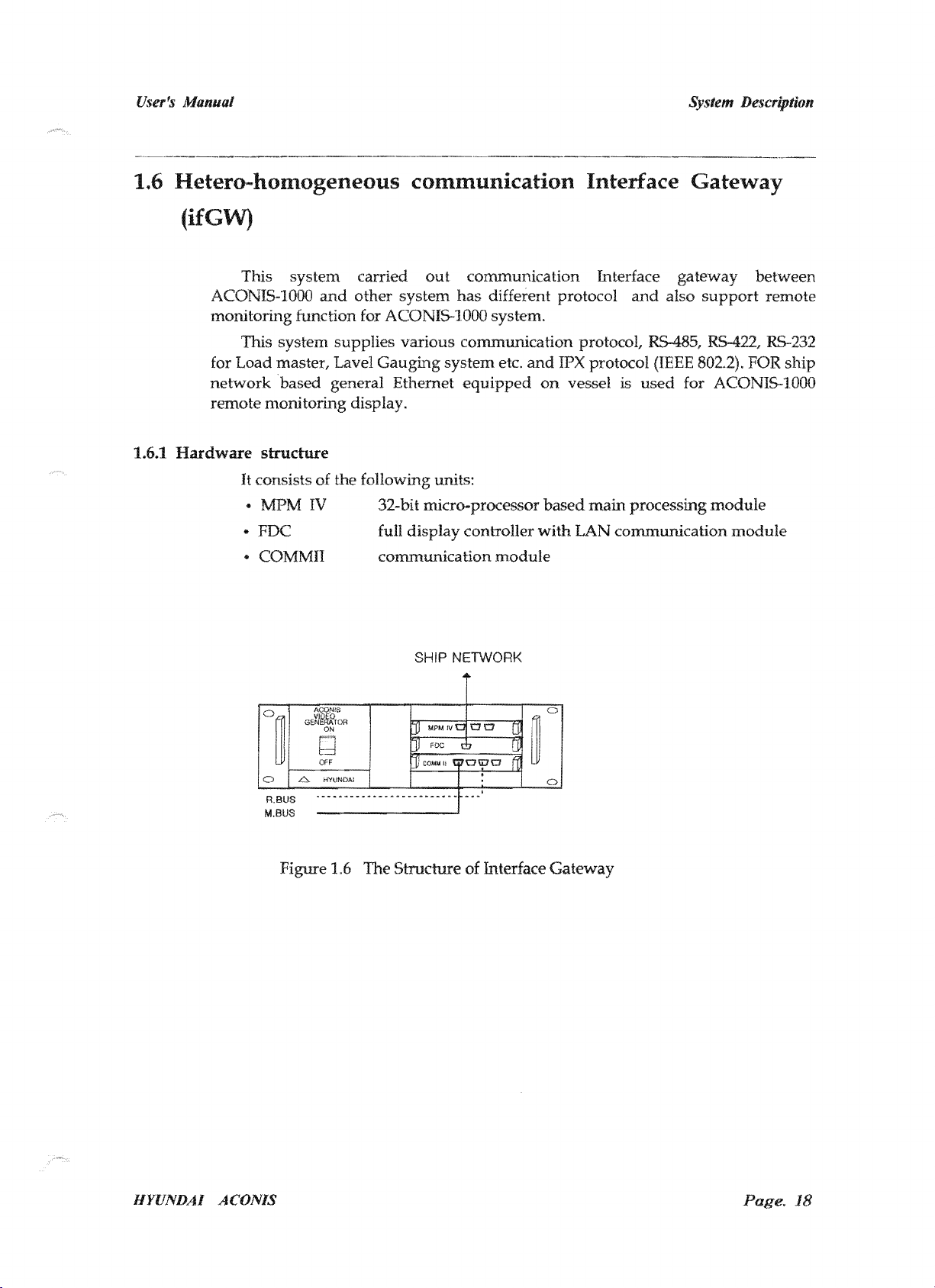
1.6
Hetero-homogeneous
communication
Interface
Gateway
(ifGW)
1.6.1
This
ACONIS-IOOO
monitoring function for
for
Hardware
structure
It
consists of the following units:
..
MPM
..
FDC
..
COMMII communication
and
IV
out
other system
ACONIS-IOOO
full
SHIP NETWORK
communication
has
different protocol
;';'l<UP'Tl
"""f"Olrri etc.
and
equipped
controller
module
IPX
on
with
protocol
vessel is
LAN
communication
between
and
module
o~
OFF
1------1
6 HYUNDAl
R.BUS
M.BUS
1.6
The
""t-'rI1C't-I1'1"t:>
of
Interface
Gateway
HYUNDAI
ACONlS
18
UJer'J
Manual
Operating Information
ACONIS-l000
Operating Information
HYl1NDAI
ACOiVNo,'
Hyundai
Heavy
Industries Co., Ltd.
Page.
1
lfser's Manual
Operating Information
Table
of
Contents
<Contents>
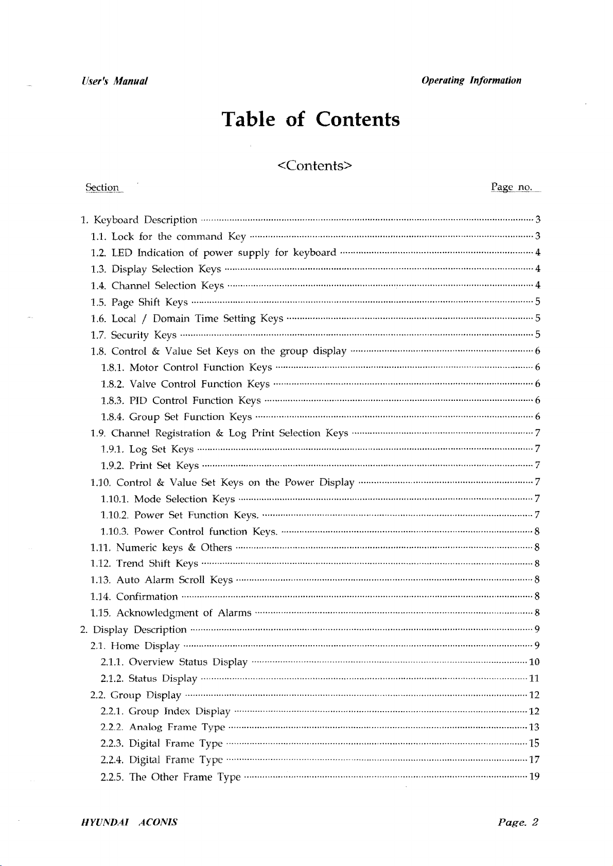
1. Keyboard Description ................................................................................................................................ 3
1.1. Lock for the comn1and Key ............................................................................................................. 3
1.2. LED Indication of
1.3. Display Selection Keys ...................................................................................
1.4. Channel Selection Keys ...................................................................................................................... 4
1.5.
Page Shift Keys .................................................................................................................................... 5
1.6. Local I Domain Time Setting Keys ............................................................................... ·
1.7. Security Keys .................................................................................................................................... ·
1.8. Control & Value Set Keys
1.8.1. Motor Control Function Keys ....................................................................................·
1.8.2. Valve Control Function Keys .................................................................................................... 6
1.8.3. PID Control Function Keys ........................................................................................................ 6
1.8.4.
Group
1.9. Channel Registration & Log Print Selection Keys
·1.9.1.
Log Set Keys .................................................................................................................................. 7
1.9.2. Print Set Keys ........................................................................................ ·
Set Function Keys ....................................................................................
power
supply
on
the
for keyboard .......................................................................... 4
··..····
group
display .......... ·..·..· .......... · ......
..··....·..
····· ..· .................. · ........ · ........ · .... · ........
..............·..·
··
......··.. ·....
···
..··
...... · .................... ··....
....
···..·4
..··....··....
· .... · .... · ...... ··6
..
· .... · ......
.. ··...... · ..· .... ··6
·5
..
·5
·6
·7
··7
1.10. Control & Value Set Keys on the Power Display
1.10.1. Mode Selection Keys .................................................................................................................. 7
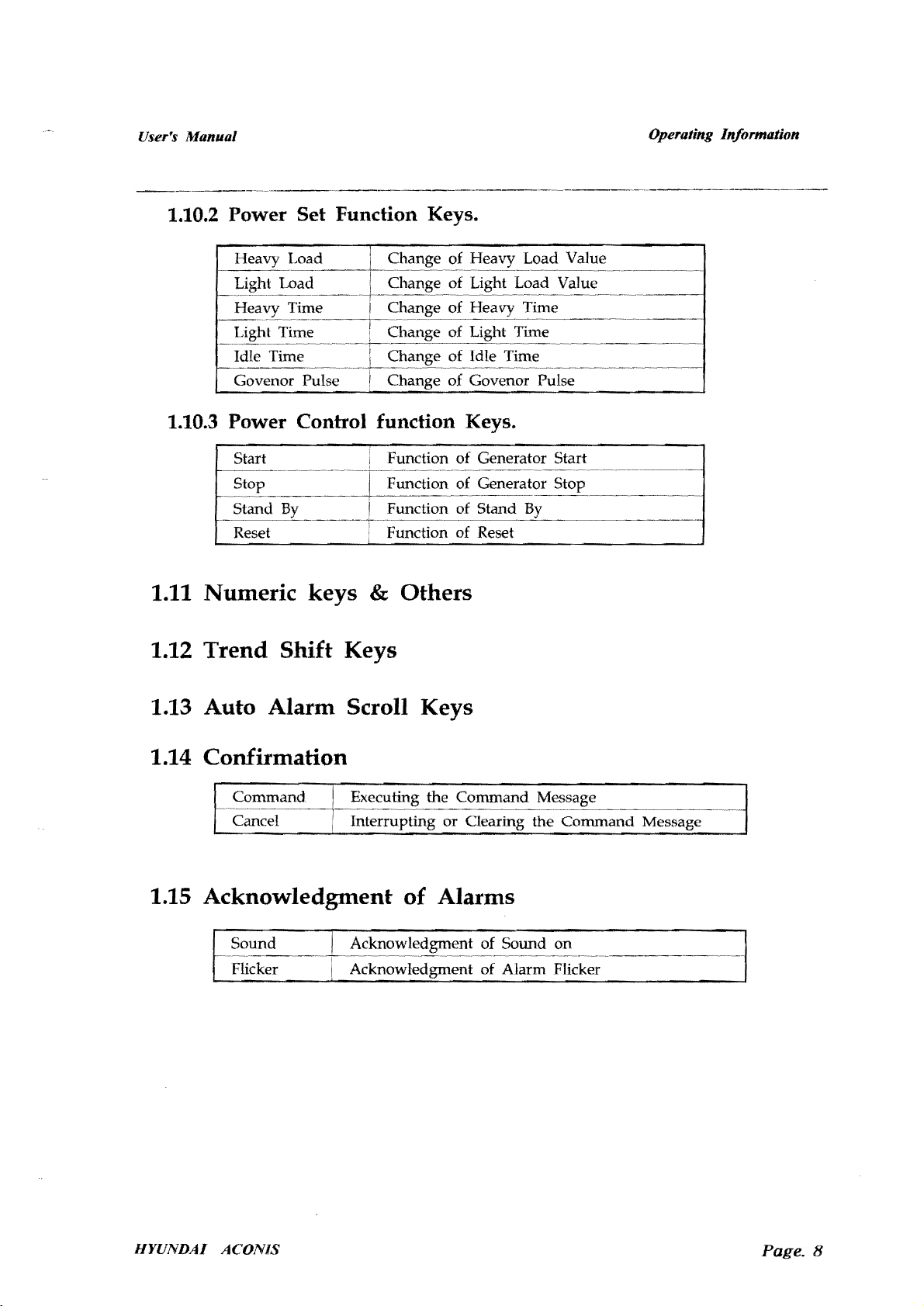
1.10.2. Power Set Function Keys ......................................................................................................... 7
1.10.3. Power Control function Keys .................................................................................................. 8
1.11. Numeric keys & Others ........................................................................................ · ....
1.12. Trend Shift Keys ................................................................................................................................ 8
1.13. Auto Alarm Scroll Keys ................· ...... · ........ ·
1.14. Confirmation ...........................................................................
1.15. Acknowledgment of Alarms ..........................................................................................
2.
Display Description .......................................................................· .... ·..··..·..
2.1.
Home
2.1.1. Overview Status Display .......................................................................................................... 10
2.1.2.
2.2.
Group
2.2.1.
2.2.2. Analog Frame Type ..........................................................................................· ....
2.2.3. Digital Frame Type ...........................................................................................· ........
2.2.4. Digital Franl€ Type .................................................................................................................... 17
2.2.5. The
Display ....................................................................................................................................... 9
Status Display ......................................................................................··..
Display ................................................................................................................................····12
Group
Index Display ................................................................................................· ........ · ......
Other
Frame Type ............................................................................................. · ............ ·
..
·· ..·····
..·..·..··..
..
· .............. · ...... · .... · ..· ...... ··........ · .... ··..·..·....·..
· .... · ..· .... ··.... · ...... · ..··
··
..·· ..
···
....··....
·· ..
······.... ······
....·....·..
··
............ · ......
···
....
···..···..·····..· .... ··....
..
·········..·····..·..····..·9
· ........ ·
....
··
........··........··11
···
.... · .... · ......
· ...... · .... 7
··
..
··
.... · .... ··8
··
.... · ...... ·
·8
·8
·8
·12
·13
..
15
..
19
IIYUNDAI ACONIS
Page.
2
User's Manual
Operating Information
<Contents>
Page no.
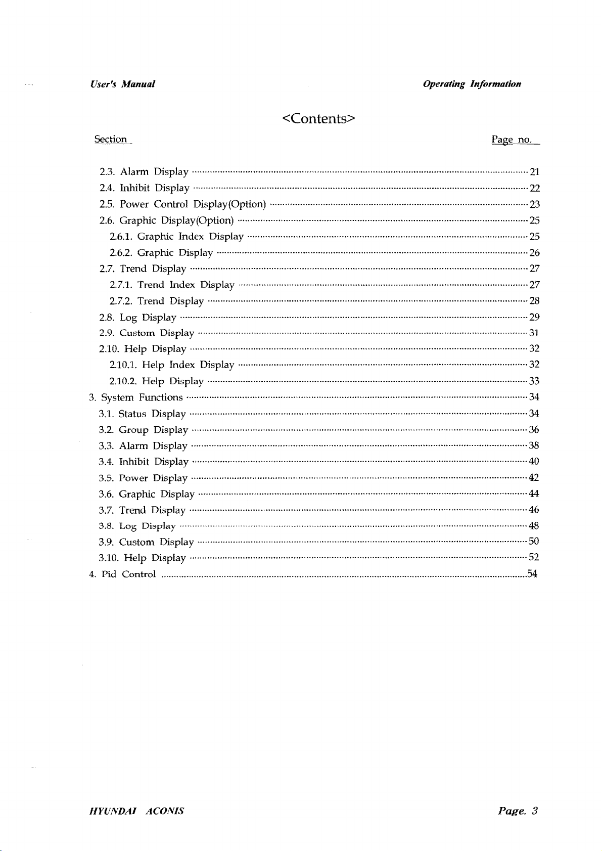
2.3.
Alarm Display ....................................................................................................................................
2.4.
Inhibit Display ........................................................................··.... ·········· ..·
2.5.
Power Control Display(Option) ..........................................................................······ .... · ...... ·
2.6.
Graphic Display(Option) ..................................................................................................................
2.6.1. Graphic Index Display ..............................................................................................................
2.6.2. Graphic Display ............................................................................................· ...... · ..· ........
2.7.
Trend Display ..................................................................................................................................... 27
2.7.1. Trend Index Display ........................................................................ ·················
2.7.2. Trend Display ..............................................................................................................................
2.8.
Log Display ......................................................................................................................................... 29
2.9.
Custom Display ...................................................................······..·
.. ·.. ·..
2.10. Help Display .....................................................................................................................................
2.10.1. Help Index Display .................................................................................................................. 32
2.10.2. Help Display .............................................................................................................................. 33
3.
System Functions ...................................................................... · ......
···..···
3.1. Status Display .....................................................................................................................................
3.2.
3.3.
Group
Alarm
Display .................................................................................................................................... 36
Display .................................................................................. · ..·..· .... ··...... ····· .... · ............
3.4. Inhibit Display ....................................................................................................................................
..·· ..
·········..·..····..···
··.. ··
......·····..·..·· ..·..··.. ·· ..·..
....··..·..
·······...... ···· ......··......
..·..
···
......·····..·
....
···
21
···
.... ·22
..
···..···23
25
25
...... ···26
..
·27
28
······31
32
···..··34
34
·· ..
·····38
40
3.5.
Power Display .....................................................................··.... ······ ..········..······..· .... · ..··
3.6. Graphic Display .....................................................................................
3.7.
Trend Display ..............................................................................··....
3.8.
Log
Display·
...... · .................................................................................................................................
···
..
···..· .... · ................ ···· ..··
· ........ ··.... ······ ..·..·
....··...... ····· ..··42
....·..
······44
.......... ····46
3.9. Custom Display .................................................................................................................................. 50
Help
3.10.
4.
Pid Control ..................................................................................................................................................54
Display .............................................................................. · ..·..······..·..··..····..·· ..
···· ....
···
....
·· .. ··..·52
48
HYUNDAI
ACONIS
Page.
3

User's
Manual
Operating Information
1.
Keyboa
optional systems. Therefore, only some of the keys are used
UMS-alarm system. Explanations of the functions of the
follows .
rd
The
ACONIS-IOOO
U.I
De
scription
keyboard is designed for the use of both
standard
numbered
1 ~ 1.6 1.1
when
items are given as
~---t----~~~~--~------~---~~:--~-~----
"""
""'
,-..
.
"",
"""
'I>
'-"'
-
11_
Dolo,
'''
~
-
....
"""
'-
0
...
".,.
""'
1.I0t-
19
1
q~
....
-
-
~--~
-
"-
.J
systems and
operating the
1.7
•
1.1
;
1 I
~
1
.1
Lock for the c
1. With th e key switch unlocked.
- The variable parameters
of alarms, setting of time etc.,
Operation of
2.
With the key switch locked.
Because
operation
HYUNDAl ACONIS
motor/pumps,
command
of
motor/pumps,
Key
I
1. lll
.1
om
is
in
.
I.IU.3
mand Key
the system, such as alarm limits, interlocking
may
valve or djesel can be avaHable also.
locked,
valve
.
1.11J.2
be changed .
Change
or
of variable
ctiesel engine starter
paramet
can't
ers is
inhibited
be available as well.
and
Page
. 4
User~fj
Manual
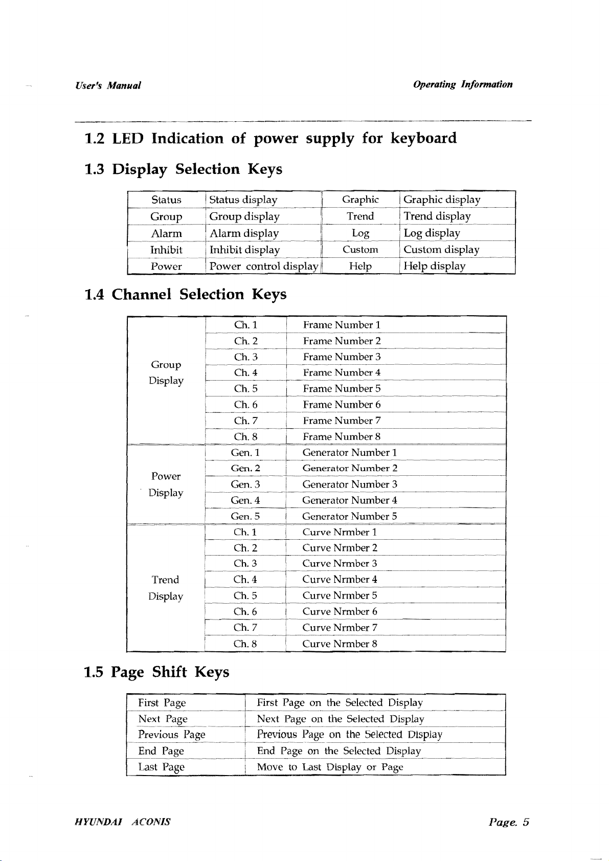
1.2
LED
Indication
of
power supply for keyboard
1.3 Display Selection Keys
1.4 Channel Selection Keys
Operating Information
Group
Display
Power
Display
Trend
Display
Ch.1
Ch.2
Ch.3
Ch.4
Ch.5
Ch.6
Ch.7
Ch.8
Gen. 1
2
Gen.
Gen. 3 Generator
Gen.S
Ch.l
Ch.2
:
:
Ch.3
Ch.4
I :
i
Ch.5
Ch.6
I
Ch.7
Ch.8
I
:
:
i
:
i
I
I
I
Frame
Frame
Frame
Frame
Frame
Frame
Frame
Frame
Generator
Generator
Generator
Curve
Curve
Curve
Curve
Curve
Curve
Curve
Curve
Number
Number
Number
Number
Number
Number
Number
Number
Ll"'HlLVl
Nrmber
Nrmber
Nrmber
Nrmber
Nrmber
Nrmber
Nrmber
Nrmber
1
2
3
4
5
6
7
8
Number
Number
Number
Number
Number
1
2
3
4
5
6
7
8
1
2
3
4
5
1.5 Page Shift Keys
First First Page
HYUNDAI
I--------~~
Next
End
Last Page
ACONIS
..
---.--.---.---+-.~.--.~.-.----.--.--.~.-.~.---.-.--.~.-
on
the Selected Display
on
the
Selected
on the Selected
Move to Last Display
or
Page
Page. 5
User's Manual
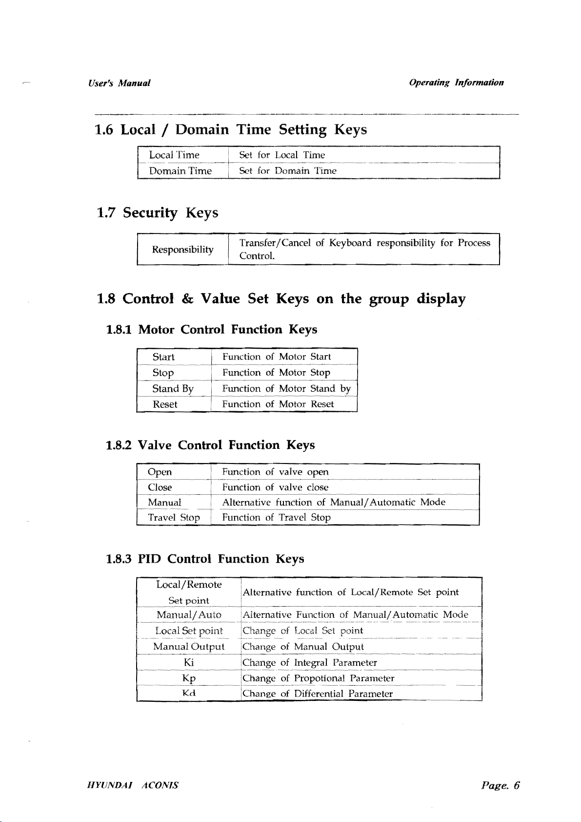
1.6
Local/Domain
1.7 Security Keys
Time
Setting
Operating Information
Keys
1.8
Control
1.8.1
Motor
-~--~.~~-.-
1.8.2 Valve
Open
Close
Manual Alternative function of
Travel
Responsibility
&
Value
Transfer/Cancel of Keyboard responsibility for Process
ControL
Set
Keys
on
Control Function Keys
Start
Stop
Stand
Reset ! Function of Motor Reset
Control
Stop~l
I Function of Motor Start
'Function
..-+..
~.~.~~-.~.--.-~---
By I Function of Motor Stand
Function
Function of valve open
Function of valve close
F~~tion
of Motor Stop
Keys
of
Travel
Stop .
the
by
Manualf
group
Automatic Mode
display
1.8.3
HYlJNDA!
PID
Control
Local/Remote
ACON!S
Function
Keys
function of Local/Remote Set
Function of
Manual!
point
Automatic Mode
Page. 6

User's Manual
Operating Information
1.8.4
1.9
Channel
1.9.1 Log
Group
Alarm High iChange of the Alarm High Limit
-.~
..
Alarm Low ;Change of the Alarm Low Limit
-~.~.-.~.--.~
Set
-.~~.~.~.~.~.---t--.~.~.~
Function
..
~-~\
----.-.--
Keys
...
~.-~
•.
~.-~.~.--.-
..
-~.~.~.~.--~~
Interlock iAlternative function of Interlock
Registration
Set
Keys
& Log
Print
Alternative Key to Select Normal
on
off
;: Daily
==
Normal
Normal/Daily
Set for
Group
~--.-~.~--------
Out
___-__
M--
____
----------r------.~.~.~.~-.
Set for
Set for Norm.al/Daily Log
''''''''TTI;.J
~----~-------------------~---------
Channel In Set for
Channel
Log
Out
Tim~
Set for
Set for Normal Log Interval Time
! Set for Daily Log Start Time
..~..
~.-.--
_.
--------~
..~..
-.-
on/l
Selection Keys
or
Daily Mode
In All Channels
Out
one
Group
In
one Channel
Out
one Channel
1.9.2
1.10
1.10.1
HYUNDAI
Print
Ail Channel
Registered Channel
Control
Mode Pop-up
_._._._~~~_.l--_~.~
Synchronizing 'Alternative function of
.-.~
~::l:~~;:Balanced~:::
Lo;d
Load Dependent Stop Alternative function
ACONIS
Set
Keys
All Channels Log Print
Registered Channels Log Print
.-.-------
&
Value
Mode
·-·-------4-·--·---·~~-·-···-···-·--·-·~·~·-···-···-·--.~.-.-
Selection Keys
.•.
-.--
.•.- .•.
-----~
D~pende~tSta-;'t
Set
Keys
Window
________
..
-.-..-.-.•-.-
IAltern~ti;~
.•
on
-.-.-.~.~.-
...
;:=;:;·~!£:::::~~S~~-
-&;cti~~·~f-Ma~uall
Out
..
~---~-.----.~.~.-~--
the
Power
Key for the Generator Mode
~.~_
--
Manual/Automatic
.•. - .•.
-.--
of
Manualj
Out
Display
... -
...-..
---------
..
--.~-.--.--.-.-.--.--.-.~.
Mode
..~..
"'~
.
..J
"
Auto~atk-
Automatic
Mode--·
..
Mode
Page.
7
User's Manual
1.10.2 Power Set Function Keys.
Govenor Pulse
1.10.3 Power Control function Keys.
Operating Information
Load Value
Load Value
Time
Time
Start
Reset
1.11 Numeric
keys
Function
Function of Reset
& Others
of
1.12 Trend Shift Keys
1.13 Auto Alarm Scroll Keys
1.14 Confirmation
Command Executing the Command Message
~C~;cel---;
1.15 Acknowledgment
Int~rrupting
or
of
Alarms
Gearing
Generator Start
the
Command
Message
HYUNDAJ
Sound
Flicker
ACONIS
n<>n'crm<>nt
Acknowledgment
of Sound
of
Alarm Flicker
on
Page. 8

User's Manual
Op
erating Information
2.
2.1 H
Display Description
om
e
Displ
The Status Display can be
screen display can
of the channels presentsed
occured can be easily recognized
screen. Through the second one, which
64
channels can be recognized on one screen
channel
can
be
ay
shown
show
in
in
detail.
I 2 J
j !
J,
,
cl
brief the status of 512 channels
with
divided
color information. The channel in
'"
,
ol
into
two
types of screen display. The first
on
one screen.
among
all the other channels registered on this
is
the status screen for the group, the status of
and
the explanation
.'
,;
7 x
,
,-l
,
~l,~
I
rl
which
about
and
status
the alarm
the relevant
1. Status display icon.
2.
3.
4.
5.
6.
7.
S.
9.
10.
11.
12.
13.
14. Next
HYUNDAI
",_-l
lf-
-r--+-~
Group
Alarm
Inhibit
Power
Graphic
Trend
Log display icon.
Custom
Help
End
first
Previous
ACONIS
display icon.
display icon.
display
display
display icon.
display
display
display
page
pugE di
page
icon.
icon.
display
:s
play
page
display
icon.
icon.
icon.
icon.
icon.
display icon.
icon.
15.
Last
page
display icon.
16.
Data
& time
and
Domain
17.
Acknowledge
18.
Acknowledge
19. Key responsibility icon.
20.
Change
21.
Change
22. User
23.
24
. U
25.
26.
Command
Key responsibility indication for
process control.
<:e
r co
Last
alarm
(Last existing
Activated reserve
di
splay
.
of
of
Local time.
Domain
mmand
display
display
alarm
window
alarm sound.
alarm
time.
Keys.
window
is
always
server
for local
flickering.
window.
display here.)
station.
Page.
9

User's Manual
Operating Information
2.1.1 Overview Status
Display
1.
All
(512channels / page)
2.
Status
Page
3.
Group
Page
display
4.
Date
Local/Domain
5.
Channel
HYUNDAI
status
ACONIS
display
display
button
display
button
no.111.
and
time
no.141S interlocked (CYAN color)
number
which
number
which
display
number
(64channels/pag
go
directly to
(8channels/page)
go
directly to
window
status
group
for
6.
Acknowledged
(RED color)
7.
e)
Channel
alarm
8.
Channel
status
9.
Channel
(GREEN color)
10. Function button.
status
(PURPLE color)
alarm
channel
no.1435
nO.1431
no.1441
unacknowledged
(RED blinking)
suppressed
normal
status
no.1418.
status
Page.
10

User's Manual
Operating Information
2.1.2 Status
Display
HYUNDAI
1.
Status display number.
Group display number.
2.
Page
button
3. Condition square marker for monitoring channel
- Normal status : GREEN
- Acknowledged alarm status : RED
- Unacknowledged alarm status : RED blinking
- Interlocking
- Suppressed status : PURPLE
4.
Channel no.3 in
ACONIS
will go directly to
status:
group
CYAN
display no.l11 gives channel no .1113.
group
display no.111.
Page.
11
 Loading...