

HYUNDAI ELEVATOR HWC W120 User Manual

RF Data Modem
HWC-M100
HWC-W100
HWC-W120
User Manual

1. Overview
RF Data Modem HWC-M100 / HWC-W100 / HWC-W120
Table of Contents
1.1 Features ㆍㆍㆍㆍㆍㆍㆍㆍㆍㆍㆍㆍㆍㆍㆍㆍㆍㆍㆍㆍㆍㆍㆍㆍㆍㆍㆍㆍㆍㆍㆍㆍ
1.2 Accessories ㆍㆍㆍㆍㆍㆍㆍㆍㆍㆍㆍㆍㆍㆍㆍㆍㆍㆍㆍㆍㆍㆍㆍㆍㆍㆍㆍㆍㆍㆍㆍㆍ
1.3 Product Description ㆍㆍㆍㆍㆍㆍㆍㆍㆍㆍㆍㆍㆍㆍㆍㆍㆍㆍㆍㆍㆍㆍㆍㆍㆍㆍㆍ
2. Installation the device
2.1 Network configuration ㆍㆍㆍㆍㆍㆍㆍㆍㆍㆍㆍㆍㆍㆍㆍㆍㆍㆍㆍㆍㆍㆍㆍㆍㆍㆍㆍ
2.2 Configure the Setting of RF-Master(HWC-M100) ㆍㆍㆍㆍㆍㆍㆍㆍㆍㆍㆍㆍㆍㆍㆍ
2.3 Configure the Setting of RF-Modem(HWC-W100) ㆍㆍㆍㆍㆍㆍㆍㆍㆍㆍㆍㆍㆍㆍㆍ
2.4 Configure the Setting of RF-Modem(HWC-W120) ㆍㆍㆍㆍㆍㆍㆍㆍㆍㆍㆍㆍㆍㆍㆍ
3. Communication with HOST
3.1
Communication method
3.2 Communication data
4. Communication with the End Device
Communication Method
4.1
4.2
5. Quick Start for GUI
Communication Data
ㆍㆍㆍㆍㆍㆍㆍㆍㆍㆍㆍㆍㆍㆍㆍㆍㆍㆍㆍㆍㆍㆍㆍㆍㆍㆍ
ㆍㆍㆍㆍㆍㆍㆍㆍㆍㆍㆍㆍㆍㆍㆍㆍㆍㆍㆍㆍㆍㆍㆍㆍㆍㆍ
ㆍㆍㆍㆍㆍㆍㆍㆍㆍㆍㆍㆍㆍㆍㆍㆍㆍㆍㆍㆍㆍㆍㆍㆍㆍ
ㆍㆍ ㆍㆍㆍㆍㆍㆍㆍㆍㆍㆍㆍㆍㆍㆍㆍㆍㆍㆍㆍㆍㆍ 22
1
3
4
10
12
14
21
21
22
5.1 Initial Screen after Execution
5.2
5.3 Status and Control of Master
5.4 Status and control of AP
5.5 Status and Control of EP
5.6 RSSI Graph
5.7 Store the RSSI Data
Network Configuration
ㆍㆍㆍㆍㆍㆍㆍㆍㆍㆍㆍㆍㆍㆍㆍㆍㆍㆍㆍㆍㆍㆍㆍㆍㆍㆍㆍㆍ 29
ㆍㆍㆍㆍㆍㆍㆍㆍㆍㆍㆍㆍㆍㆍㆍㆍㆍㆍㆍㆍㆍㆍㆍㆍㆍ 30
ㆍㆍㆍㆍㆍㆍㆍㆍㆍㆍㆍㆍㆍㆍㆍㆍㆍㆍㆍㆍ 23
ㆍㆍㆍㆍㆍㆍㆍㆍㆍㆍㆍㆍㆍㆍㆍㆍㆍㆍㆍㆍㆍㆍㆍ 25
ㆍㆍㆍㆍㆍㆍㆍㆍㆍㆍㆍㆍㆍㆍㆍㆍㆍㆍㆍㆍㆍㆍ 26
ㆍㆍㆍㆍㆍㆍㆍㆍㆍㆍㆍㆍㆍㆍㆍㆍㆍㆍㆍㆍㆍㆍ 27
ㆍㆍㆍㆍㆍㆍㆍㆍㆍㆍㆍㆍㆍㆍㆍㆍㆍㆍㆍㆍㆍㆍ 28
5.8 CH RSSI ㆍㆍㆍㆍㆍㆍㆍㆍㆍㆍㆍㆍㆍㆍㆍㆍㆍㆍㆍㆍㆍㆍㆍㆍㆍㆍㆍㆍㆍㆍㆍ 31
5.9 EP Communication Count ㆍㆍㆍㆍㆍㆍㆍㆍㆍㆍㆍㆍㆍㆍㆍㆍㆍㆍㆍㆍㆍㆍ 32
5.10 Download ㆍㆍㆍㆍㆍㆍㆍㆍㆍㆍㆍㆍㆍㆍㆍㆍㆍㆍㆍㆍㆍㆍㆍㆍㆍㆍㆍㆍㆍ 33
5.11 Configure the setting of communication with device
5.12 Others ㆍㆍㆍㆍㆍㆍㆍㆍ
ㆍㆍㆍㆍㆍㆍㆍㆍㆍㆍㆍㆍㆍㆍㆍㆍㆍㆍㆍㆍㆍ 35
ㆍㆍㆍㆍㆍㆍㆍㆍㆍㆍㆍ 34
6. Dimension
6.1 RF Master(HWC-M100) ㆍㆍㆍㆍㆍㆍㆍㆍㆍㆍㆍㆍㆍㆍㆍㆍㆍㆍㆍㆍㆍㆍㆍ 36
6.2 RF Modem(HWC-W100) ㆍㆍㆍㆍㆍㆍㆍㆍㆍㆍㆍㆍㆍㆍㆍㆍㆍㆍㆍㆍㆍㆍㆍ 37
6.3 RF Modem(HWC-W120) ㆍㆍㆍㆍㆍㆍㆍㆍㆍㆍㆍㆍㆍㆍㆍㆍㆍㆍㆍㆍㆍㆍㆍ 38

RF Data Modem HWC-M100 / HWC-W100 / HWC-W120
1. Overview
1.1 Features
∎ A license and qualification of application of the radio station are unnecessary.
∎ RF Range
- Indoor/Urban up to 75m(depending on environment)
- Outdoor(line-of-sight) up to 300m
∎ Communication Interface
[RF Master(HWC-M100)]
- Ethernet port(for Host) : 10/100Base-T, UDP
- Serial port(for Debug) : RS-232(57600bps,8-N-1)
- Interface with HWC-W100 through ethernet
[RF Modem(HWC-W100)]
- RS-232/422/485(for Device) : 4800~38400bps, 8-N-1
- Serial port(for Debug) : RS-232(57600bps,8-N-1)
- Interface with HWC-W100 through ethernet
- Interface with HWC-W120 through RF
[RF Modem(HWC-W120)]
- RS-232/422/485(for Device) : 4800~38400bps, 8-N-1
- Serial port(for Debug) : RS-232(57600bps,8-N-1)
- Interface with HWC-W100 through RF
∎ Wireless Interface
- Based on the IEEE 802.15.4 DSSS(Direct Sequence Spread Spectrum)
- ISM 2.4GHz operating frequency band
∎ RF Modem Diversity(Antenna Diversity-Dedicated Receive Port)
- Reduced the Multi-pass interference in the communication between moving-vehicles.
∎ Interactive wireless communication
- Half-duplex packet-communication based on Time-division-multiple-access
- Supports the interactive communication between devices with RF-Modem
∎ Supports up to 16 RF channels in the same area
1

RF Data Modem HWC-M100 / HWC-W100 / HWC-W120
- RF Channel can be selected by rotary switch in front panel of RF-Modem
- The RF Channel of HWC-W100 and HWC-W120
∎ N:M network supply
- One RF-Master(HWC-M100) can manage N RF-Modem(HWC-W100) in AP-mode
- RF-Modem (HWC-W100) in EP-mode can bypass the data to other modem(HWC-W100).
- One RF-Modem(HWC-W100) can manage N RF-Modem(HWC-W120) in EP-mode
∎ Supports the special GUI to optimize the RF devices in RF Environment
In each AP, you can identify the frequency usage of 2.4GHz band through GUI and see the
variation of RSSI according to movement of EP.
∎ Serial communication type can be selected in RS-232,RS-422 and RS-485 through GUI
- HWC-W100 and HWC-W120
∎ Supply Voltage : DC 24V(Input Range : DC 8V ~ DC 32V) (HWC-M100, HWC-W100, HWC-W120)
∎ Operating Temperature : -30°C ~ 80°C (HWC-M100, HWC-W100, HWC-W120)
∎ RF Modem Specification (HWC-W100, HWC-W120)
항목 내용 비고
Operating Frequency 2,400MHz ~ 2,483.5MHz CFR47 part 15
Transmit Power 1mW and less
Occupied Bandwidth 3MHz and less
Spread Spectrum DSSS(Direct Sequence SS)
Modulation O-QPSK
DS-SS 32-chip PN code 2MChips/s chips rate
Communication Method Half duplex
RF Data Rate 250Kbps
Data Format @@
Channel Spacing 5MHz
RF Channels 16 Channels
Frequency Stability ±10 ppm
Transmit Spurious -40dBm
Receiver Sensitivity High sensitivity -94dBm
2

1.2 Accessories
∎ RF Master(HWC-M100)
∎ RF Modem(HWC-W100)
RF Data Modem HWC-M100 / HWC-W100 / HWC-W120
∎ RF Master(HWC-W120)
3
1.3 Product Description
∎ RF Master(HWC-M100)
RF Data Modem HWC-M100 / HWC-W100 / HWC-W120
4

RF Data Modem HWC-M100 / HWC-W100 / HWC-W120
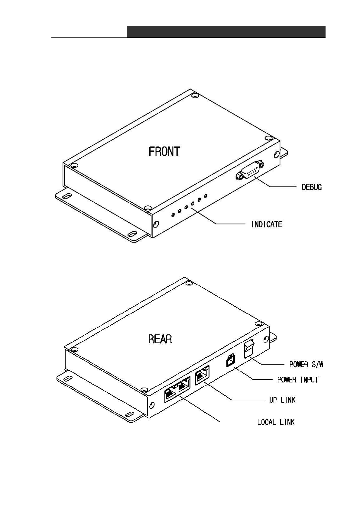
① Debug
- Connecting PC or Notebook to debug port, you can set control data and see the
operating status of device.
② Indicator
- Indicate the operation status of device, visually.
PWR LED : DC power supply is ok
RUN LED : Blink in normal operation of device
UP LED : Ethernet communication with the HOST
LOCAL LED : Ethernet communication with the AP
ALM LED : Turn on RED in case of fault operation
③ Power S/W
- DC power on/off switch
④ Power Input
- Connector to supply dc power(DC 24V)
- Using reverse voltage protect circuit, ensure device against the reverse voltage
⑤ Up_Link
- Ethernet port to communicate with upper HOST
⑥ Local_Link
- Ethernet port to communicate with lower AP
5
∎ RF Modem(HWC-W100)
RF Data Modem HWC-M100 / HWC-W100 / HWC-W120
6

RF Data Modem HWC-M100 / HWC-W100 / HWC-W120
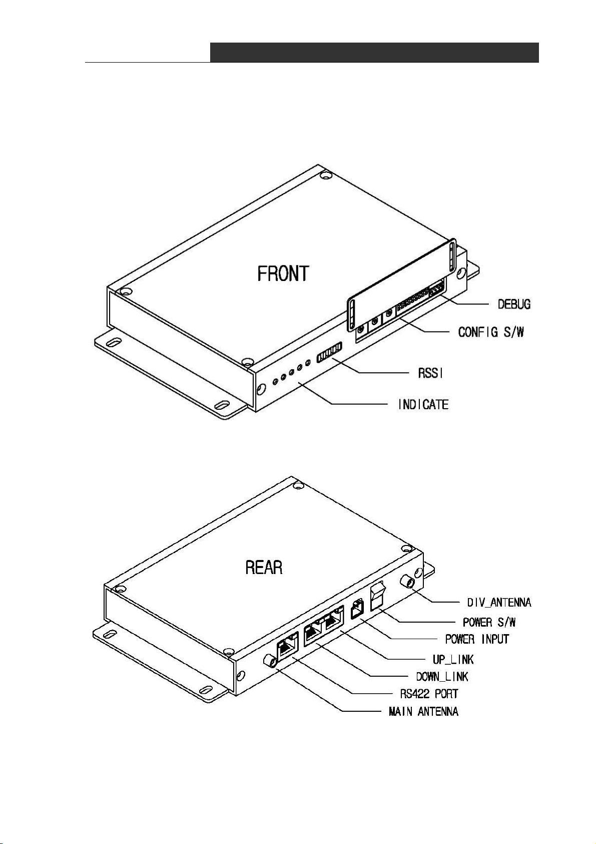
① Debug
- Connecting PC or Notebook to debug port, you can configure parameter of modem and see
the operation status of the device.
② Configuration S/W
- You can use this switch to configure nework-ID, devide-ID, communication-type and so
on.
③ RSSI
- Display the strength of receiving RF signal in LED segment
④ Indicator
- Indicate the operation status of device, visually.
PWR LED : dc power supply is ok
RUN LED : blink in normal operation of device
TX LED : turn on in data transmission to End Device
RX LED : turn on in data reception from End Device
ALM LED : turn on RED in fault operation
⑤ Main/Div Antenna
- bi-directional antenna for RF communication. It consist of main and diversity antenna.
⑥ Power S/W
- DC power on/off switch
⑦ Power Input
- connector to supply dc power(DC 24V)
using bridge-diode in the internal circuit, ensure device against the reverse voltage
⑧ Up/Down_Link
- ethernet port to receive data from RF-Master and transmit data to another AP
⑨ Serial Communication Port
- Serial port to communicate with lower device.
- You can select communicate type : RS-232 or RS-422 or RS-485.
7
∎ RF Modem(HWC-W120)
RF Data Modem HWC-M100 / HWC-W100 / HWC-W120
8

RF Data Modem HWC-M100 / HWC-W100 / HWC-W120
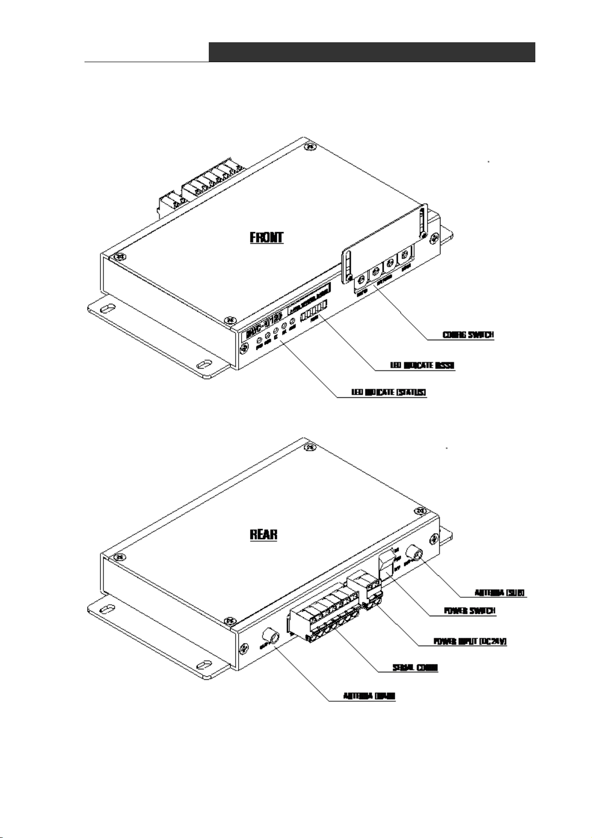
① Debug
- Connecting PC or Notebook to debug port, you can set control data and see the
operating status of device.
② Indicator
- Indicate the operation status of device, visually.
PWR LED : DC power supply is ok
RUN LED : Blink in normal operation of device
UP LED : Ethernet communication with the HOST
LOCAL LED : Ethernet communication with the AP
ALM LED : Turn on RED in case of fault operation
③ Power S/W
- DC power on/off switch
④ Power Input
- Connector to supply dc power(DC 24V)
- Using reverse voltage protect circuit, ensure device against the reverse voltage
⑤ Serial Communication Port
- Serial port to communicate with lower device.
- You can select communicate type : RS-232 or RS-422 or RS-485.
9
RF Data Modem HWC-M100 / HWC-W100 / HWC-W120
2. Installation the device
2.1 Network configuration
10

RF Data Modem HWC-M100 / HWC-W100 / HWC-W120
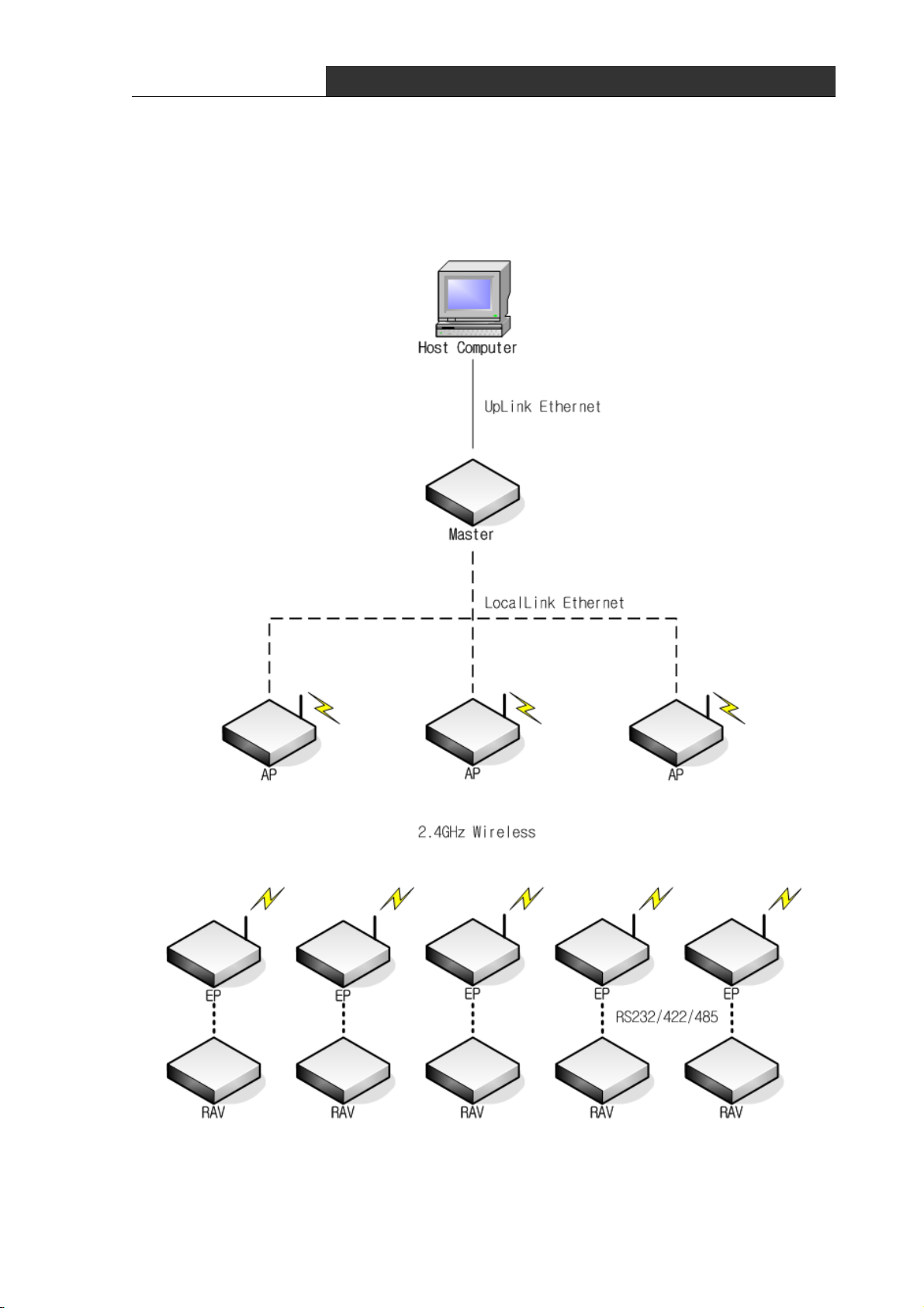
∎ The network consists of one RF-Master(HWC-M100) and several AP(Access Point)/EP(End
Point)
∎ You can set AP(Access Point) or EP(End Point) mode of RF Master(HWC-M100) using
configuration-Switch.
∎ Communication between HOST and RF-Master can be implemented in public or private
network.
∎ One RF-Master can be connected to several AP in ethernet communication. It can be
implemented in multi-drop bus for interconnecting RF-Master and APs.
∎ RF-Master manages network that relays the communication of HOST and lower equipment.
∎ AP(Access poing) Managed by RF-Master relays data in which Host delivers to EP. When
the shadow region exists with a AP, AP can be additionally installed and the coverage can
be expanded.
∎ EP(End Point) is connected with a subordinate equipment by wire and supports a
communication with HOST. You can select one of the RS232/RS422/RS485 to communicate with
the lower equipment.
11
 Loading...