


Hyundai Electronics H-CCR4701M User manual
H-CCR4701M
USB/SD MEDIA PLAYER
WITH 7” MOTORIZED
TFT-DISPLAY,
TV-TUNER AND BLUETOOTH
USB/SD МЕДИАПЛЕЕР
С 7” МОТОРИЗИРОВАННЫМ
TFT-ДИСПЛЕЕМ,
ТВ-ТЮНЕРОМ И BLUETOOTH
Руководство по эксплуатации Instruction manual
Table of contents
Dear customer!
Thank you for purchasing our product. For safety, it is strongly recommended to read
this manual carefully before connecting, operating and/or adjusting the product and keep
the manual for reference in the future.
Table of contents
Before you start
Utilization of the product
Important safeguards
Installation/Connection
Installation
General notes
Mounting
Detachable control panel
Anti-theft system
Connection
Connection diagram
Using the ISO Connector
ISO connection table
Parking wire connection
Reverse driving cable connection
Operation
Control elements
Front panel
Remote controller
Changing the battery
General operations
Touch screen
Turning the unit on/off
Reset the unit
Volume control
Setting the sound characteristics
Mute function
Mode selection
Angle setting
AV in jack
Subwoofer
System setup
Sound presets
Settings page
Radio operations
User interface of Radio mode
Band selection
Manual/automatic tuning
2
Programming tuner stations
3
Auto memory store
3
AF (Alternative frequencies) function
3
TA (Traffic alarm) function
4
Program type (PTY)
4
TV tuner operations
4
USB/SD/MMC operations
4
USB/SD/MMC notes
5
Inserting a memory card/USB device
5
Music mode touch interface
6
Play/pause
6
Selecting tracks
7
Fast forward/rewind
7
Repeat playback
8
Movie mode touch interface
8
Rotate function
9
Zooming in/out
9
ID3 tag function
9
Photo mode touch interface
10
Cleaning the unit body
10
Accessories
10
Troubleshooting guide
10
Specification
10
10
11
11
11
11
11
11
11
11
11
12
12
12
12
12
12
12
12
13
13
13
13
13
14
14
14
14
14
14
14
15
15
15
15
15
15
16
17
2

Before you start
Utilization of the product
If you want to dispose this product, do not mix it with general household waste. There is
a separate collection system for used electronic products in accordance with legislation
that requires proper treatment, recovery and recycling.
Please contact your local authorities for the correct method of disposal. By doing so, you
will ensure that your disposed product undergoes the necessary treatment, recovery and
recycling and thus prevent potential negative effects on the environment and human health.
Important safeguards
• Read carefully through the manual to
familiarize yourself with this unit.
• Keep this manual handy as a reference
for operating procedures and precautions. Do
not allow persons who have not read through
this manual to use this unit.
• Do not allow this unit to come into contact
with liquids. Electrical shock could result. Also,
damage to this unit, smoke, and overheating
could result from contact with liquids or dust.
Protect this unit from moisture.
• Make sure that foreign objects do not get
inside the unit; they may cause malfunctions,
or create safety hazards such as electrical
shock or laser beam exposure.
• The beginning of operation is the moment
of the unit installation. Before use the device
in winter it is recommended to heat up the
passenger compartment during 20 seconds or
to the operation temperature.
• Using the unit with the temperature that
goes beyond the operation temperature greatly
decreases the operation resource of the screen
and other components of the unit and can
result in an outage.
• Disconnect the vehicle’s negative battery
terminal while mounting and connecting the
unit.
• The unit is designed for negative
terminal of the battery, which is connected
to the vehicle metal. Please ensure it before
installation.
• When replacing the fuse, be sure to use
one with an identical amperage rating. Using a
fuse with a higher amperage rating may cause
serious damage to the unit.
• Do not allow the speaker wires to be
shorted together when the unit is switched
on. Otherwise it may overload or burn out the
power amplifier.
• Make sure you disconnect the power
supply and aerial if you will not be using
the system for a long period or during a
thunderstorm.
• Make sure you disconnect the power
supply if the system appears to be working
incorrectly, is making an unusual sound, has
a strange smell, has smoke emitting from it
or liquids have got inside it. Let a qualified
technician check the system.
• Always keep the volume low enough so
that you can hear sounds from outside the
vehicle.
• Should this product fail to operate
properly, contact your dealer or nearest service
center.
3
Installation/Connection
Installation
General notes
• Choose the mounting location where the
unit will not interfere with the normal function of
the driver.
• Before finally installing the unit, connect
the wiring and make sure that the unit works
properly.
• Consult with your dealer if installation
requires drilling of holes or other modifications
of the vehicle.
• Install the unit where it does not get in the
driver’s way and cannot injure the passenger if
there is a sudden stop, like an emergency stop.
• If installation angle exceeds 30° from
horizontal, the unit may not perform properly.
• Avoid installing the unit where it would
be subject to high temperature, such as from
direct sunlight, or from hot air, from the heater,
or where it would be subject to dust, dirt or
excessive vibration.
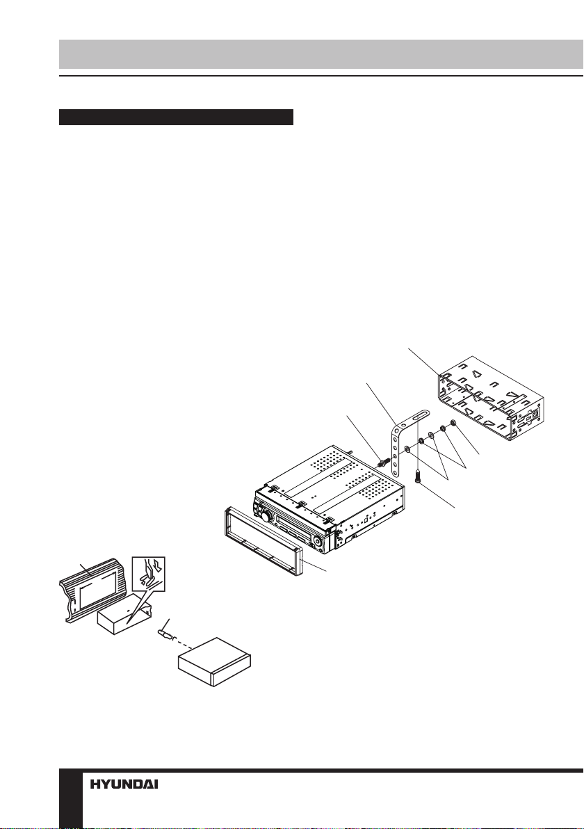
1.DIN front-mount
1. Metal strap
2. Screw
3. Bolt
4. Flat washer
5. Spring washer
6. Nut (5mm)
7. Sleeve
8. Trim frame
1
182
2
elements, etc) for the unit installation.
2. After installing the sleeve into the
dashboard, bend tabs fitting to the size of the
dashboard to fix the sleeve in place.
3. Use the metal strap to fix the rear side of
the unit. Determine a place for fixing and install
the strap as shown in the picture. You can bend
the strap to the needed angle with your hands.
4. Make the necessary wire connections.
Ensure the connections are correct.
5. Install the unit into the sleeve until the side
locks are fixed.
7
1
3
6
5
4
2
8
53
3
1. Install the sleeve into the dashboard;
ensure it is installed with the correct side and
there are no obstacles (wires, dashboard
4
Installation/Connection
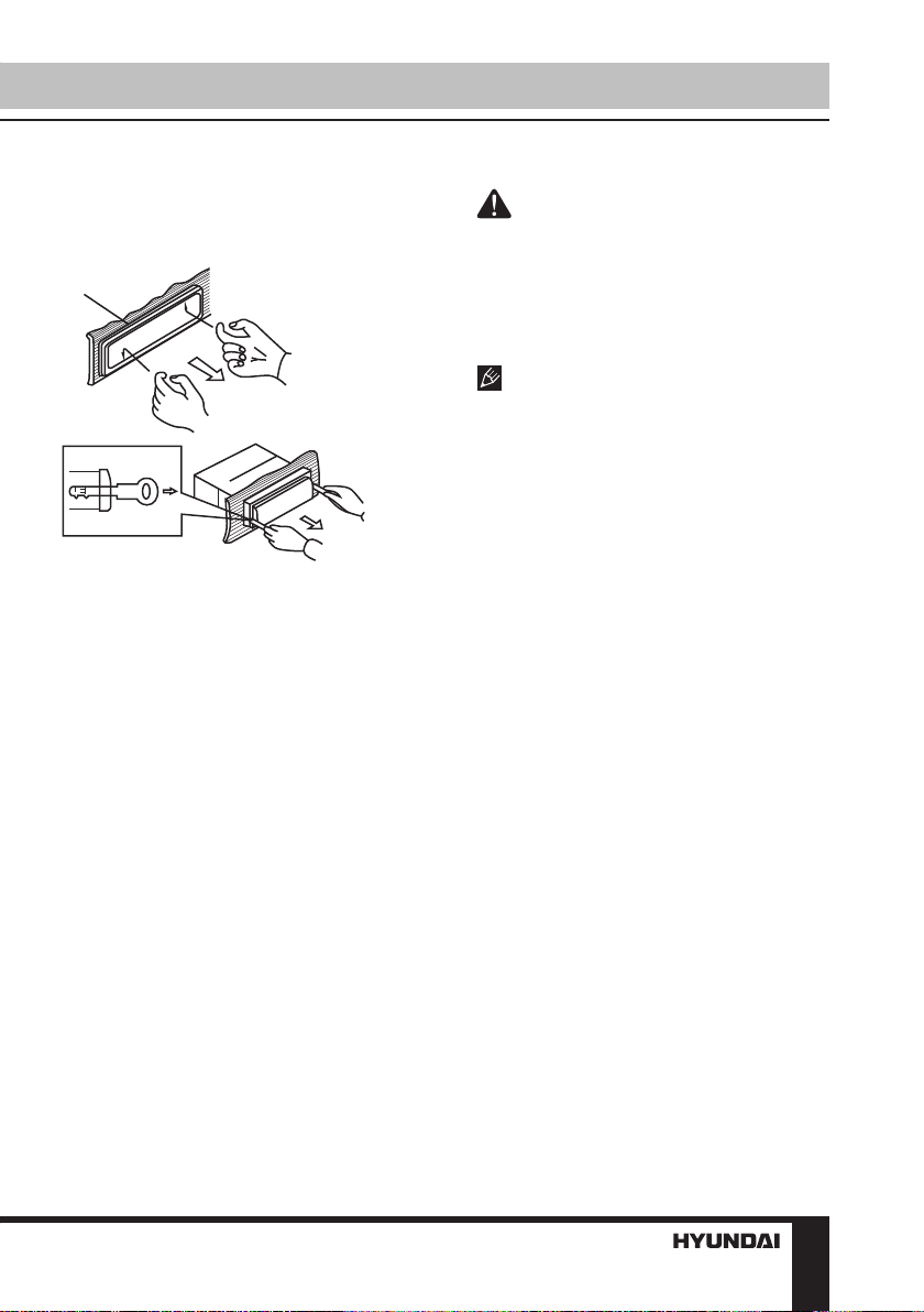
Dismantling the unit
a – Trim frame
b – Frame uninstall direction
c – Release key insertion
а
б
в
1.
Switch off the unit and detach the front panel.
2. Insert your fingers into the groove in the
front side of the trim frame (apply some effort to
detach the frame). Pull the frame to detach it.
3. Insert the supplied release keys into the
both sides of the unit body to click, as shown
in the picture. To extract the unit from the
dashboard, pull the release keys or the unit body
to pull it out. Before detaching the unit, ensure it
is not fixed with the metal strap.
the locker.
The control panel can be easily
damaged by shocks. After removing it, place
it in a protective case and be careful not to
drop it or subject it to strong shocks. The rear
connector that connects the main unit and the
control panel is an extremely important part. Be
careful not to damage it by pressing on it with
fingernails, pens, screwdrivers, etc.
If the control panel is dirty, wipe off the
dirt with soft, dry cloth only. And use a cotton
swab soaked in isopropyl alcohol to clean the
socket on the back of the control panel.
Anti-theft system
The front panel of this unit can be stored in
the included protective case when not in used
and carried away when you leave the vehicle
to deter theft.
Switch off the power of the unit. Detach the
front panel, then put it to the protective case
and take it with you.
Trim frame installation
To install the trim frame, press it to the unit
body and push it to fix it in place. This should
be done before installing the front panel;
otherwise you are not able to install the trim
frame. When the trim frame being installed,
the side with the groove should face down and
fixed first.
Detachable control panel
Insert the right lockers on the receiver into
the right grooves of the panel, and then press
on the left part of the panel until a click. Ensure
the panel is fixed properly.
To detach the front panel, press RELEASE
button. Detach the right part of the panel from
5
Installation/Connection
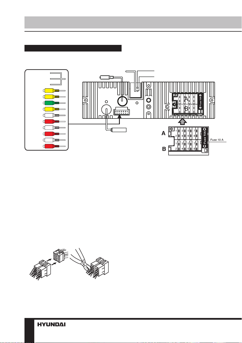
Connection
Connection diagram
SWC 1(BROWN)
SWC 2A(WHITE)
SWC 2B(GREY)
BACK CAM
VIDEO OUT
SUB OUT
AUX VIDEO
AUX IN
( L)
AUX IN
( R)
RCA OUT
( F L)
RCA OUT
( F R)
RCA OUT
( R L)
RCA OUT
( R R)
TV Antenna
HDMI
Parking (green)
Reverse(purple-white)
Radio Antenna
ConnectorA
1. Rear rightspeaker(+)/Purple
Rear rightspeaker(-)/Purple-Black
2.
3. Frontright speaker(+)/Grey
Frontright speaker(-)/Grey-Black
4.
5. Frontleftspeaker(+)/White
6.
Frontleftspeaker(-)/White-Black
7.
Rear left speaker(+)/Green
8.
Rear left speaker(-)/Green-Black
Using the ISO Connector
1. If your car is equipped with the ISO
connector, then connect the ISO connectors as
illustrated.
6
ConnectorB
1. -
2. -
3. -
4. Battery 12V(+)/Ye llow
5. Antennapower/Blue-White
6. Panel light/Orange-White
7. ACC+/Red
8. Ground/Black
2. For connections without the ISO
connectors, check the wiring in the vehicle
carefully before connecting, incorrect connection
may cause serious damage to this unit.
Cut the connector, connect the colored leads
of the power cord to the car battery as shown
in the colour code table below for speaker and
power cable connections.
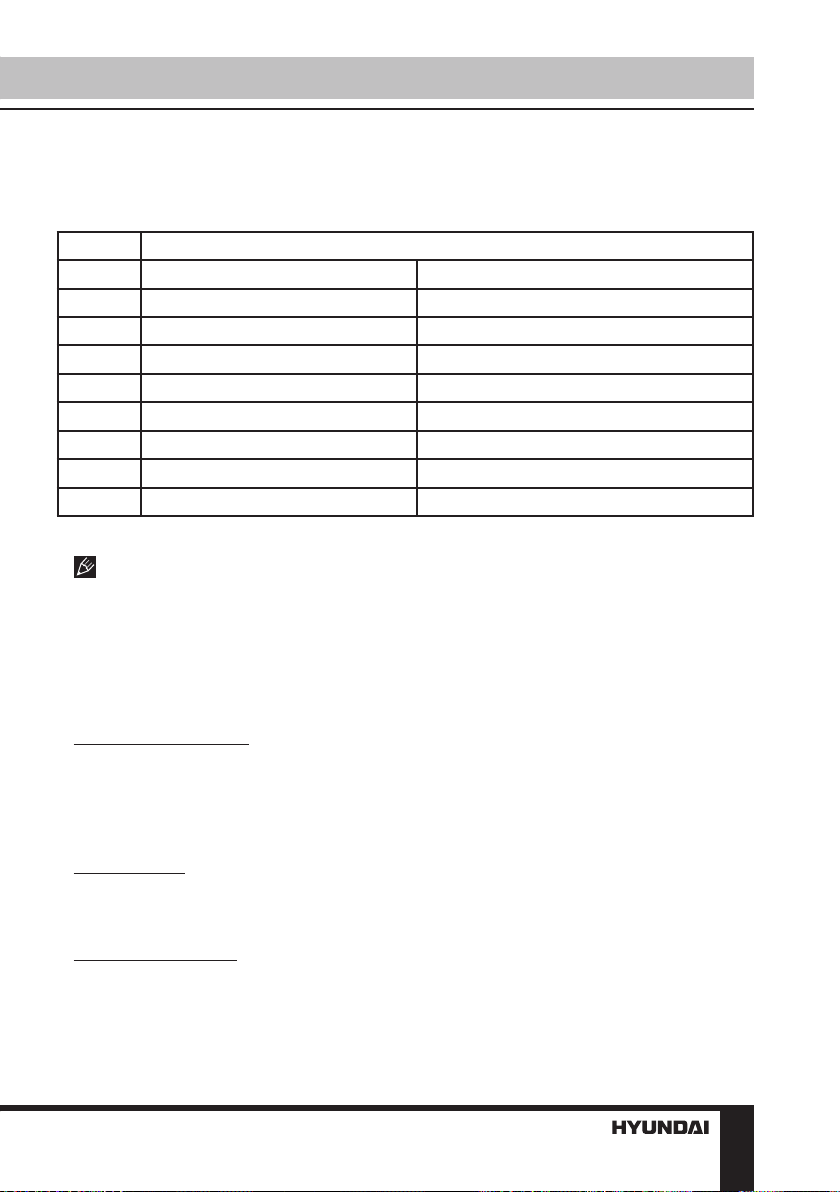
Installation/Connection
ISO connection table
Location Function
Connector B Connector A
1 Rear right (+) - Purple 2 Rear right (-) - Purple/Black 3 Front right (+) - Grey 4 Front right (-) - Grey/Black Battery +12V/Yellow
5 Front left (+) - White Antenna power/Blue-White
6 Front left (-) - White/Black Panel light/Orange-White
7 Rear left (+) - Green Ignition/Red
8 Rear left (-) - Green/Black Ground/Black
Power antenna wire is intended for power supply of the antenna and for remote control of
an additional amplifier.
AV Input
The AV Input jack is a set of composite inputs on the rear of the unit. Press the MOD
button to choose AUX. You can use it to connect any portable audio/video devices
such as a DVD player or VCD player to the unit. Refer to the Connection diagram for
more details.
Backup Camera Input
The backup camera input is on the back of the unit. (refer to wiring diagram). This
input (in yellow) is for connecting backup camera for parking. You must connect the
VCC wire (purple-white) to the reverse gear switch in order to activate this video input
mode when you switch the reverse gear of your car. Please refer to the wiring diagram
for more details.
Video Output
The Video out jack (in yellow) is for connecting monitor(s). You must connect a car
monitor in order to operate this unit in another monitor. Consult your dealer for any
kinds of monitors that are suitable to use in car.
RCA Output (2 sets)
The RCA out jacks are for connecting amplifiers, equalizers, or other audio
components that require a pre-amp out connection. (Red=Right, White=Left) Follow
the manufacturer’s instructions for the audio component that you are connecting.
7
Installation/Connection
Subwoofer Output
The Subwoofer Out jack (in green) is for connecting up to 2 subwoofer amplifiers.
Follow the amplifier’s installation instructions.
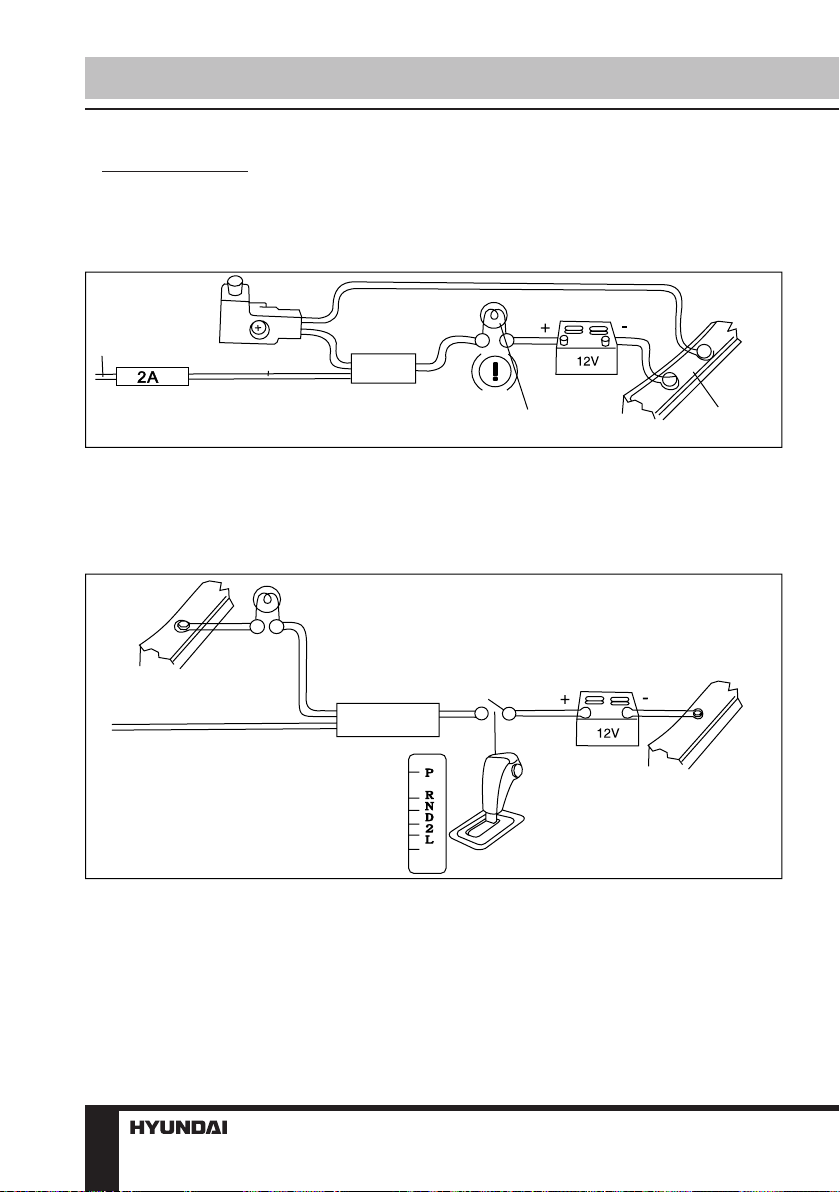
Parking wire connection
Parking brake lead
Green Wire
Brake light
Battery
Car frame
If Parking cable is connected to hand brake switch, the video display of the TFT monitor will be
controlled by driving status, system setup and input video sources.
Reverse driving cable connection
Car frame
Purple-white wire
Rear view video camera lead
If the rear view video camera is connected, the unit automatically switches to CAMERA source
during reverse driving. The unit returns to the original work mode after the reverse driving is done.
Reverse driving light
Gearbox
Battery
Car frame
8
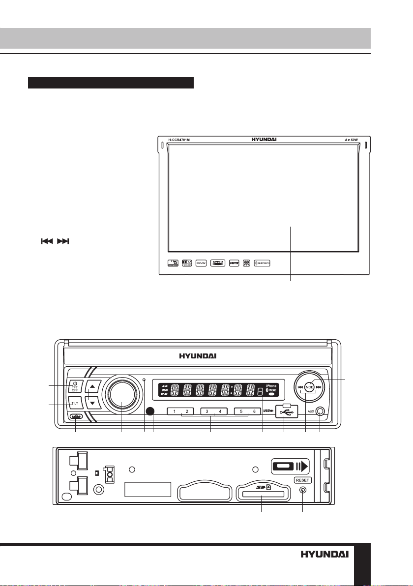
Control elements
Front panel
1. TFT display
2. POWER/TFT OFF button
3. UP/DOWN buttons
4. TILT button
5. OPEN button
6. Volume knob/SELECT button
7. Microphone
8. IR sensor
9. 1-6 buttons
10. LCD display
11. USB port (under plastic cover)
12. / buttons
13. AUX input
14. MOD button
15. SD/MMC card slot
16. RESET button (hole)
Operation
1
2
3
4
5 6 7 8 9
11
10 12 13
15
16
14
9
Operation
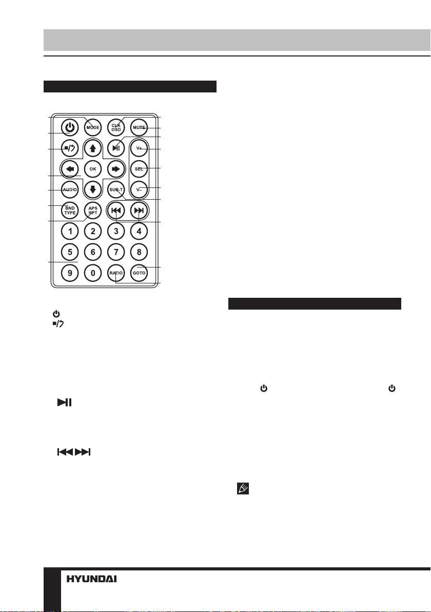
Remote controller (RC)
1
2
3
4
5
6
7
8
1. MODE button
2. button
3. button
4. OK button/Cursor buttons
5. AUDIO button
6. BND/TYPE button
7. APS/RPT button
8. Number buttons
9. CLK/OSD button
10. MUTE button
11. button
12. V+ button
13. SEL button
14. V- button
15. SUB-T button
16. / buttons
17. GOTO button
18. RATIO button
Changing the battery
1. Press the catch and at the same time pull
out the battery tray.
9
10
11
12
13
14
15
2. Insert 1 lithium battery, type CR 2025 3 V
with (+) mark facing up. Insert the battery tray
into the remote control.
• Store the battery where children cannot
reach. If a child accidentally swallows the
battery, consult a doctor immediately.
• Do not recharge, short, disassemble or
heat the battery or dispose it in a fire.
• Do not expose or bring into contact the
battery with other metallic materials. Doing this
may cause the battery to give off heat, crack or
16
start a fire.
• When throwing away or saving the battery,
wrap it in tape and insulate; otherwise, the
battery may give off heat, crack or start a fire.
17
18
• Please direct the Remote controller to the
IR sensor of the front panel.
General operations
Touch screen
The touch screen enables you to carry out
most functions not only by pressing buttons but
also by touching the options you need.
Turning the unit on/off
Press /TFT OFF button on the panel or
button on the RC to turn the unit on. Press and
hold the button to turn the unit off.
Sliding out the monitor
Press the TILT button so that the monitor
will slide out automatically and the main GUI
display will show up. Press the TILT button
again so that the screen will go back in the
chassis.
Please do not adjust the monitor tilt
manually, otherwise it can get damaged
Angle of the screen
Press the UP/DOWN arrow buttons so that
10
Operation
the screen will tilt up or down. There are 4
steps for tilting (ANGLE 0-4).
Reset the unit
Operating the unit for the first time or after
replacing the car battery, you must reset the
unit. Press reset button on the unit with a
pointed object (such as a ballpoint pen) to set
the unit to initial state.
When some errors occur on the display,
you can also press reset button to resume to
normal, and it will erase the clock setting and
some memorized functions.
TFT display on/off
When the unit is on, press /TFT OFF
button on the panel to switch off the display.
When the display is off, the video out signal will
be available so that the connected monitor will
show the screen of the unit. Press this button
again to resume the image.
Mode selection
• Press repeatedly MOD button on the panel
or MODE button on the RC to select among
Radio, USB, Memory Card, auxiliary input
(AUX), TV, Bluetooth and HDMI operation
modes. Modes of operation are indicated on
the display. Memory card and USB modes are
not available unless a memory card or USB
device is connected.
Audio parameter setting
Press SELECT button on the panel or
SEL button on the RC repeatedly to select a
parameter: VOL (volume) => BASS (bass) =>
TRE (treble) => BAL (balance) => FAD (fader).
Rotate VOLUME knob on the panel or pressing
V+/V- buttons on the RC to adjust each mode:
• Volume: from 0 to 39;
• Bass/Treble: from -7 to 7;
• Balance: L7 (left) to R7 (right);
• Fader: from R7 (rear) to F7 (front);
Additional audio settings
You can adjust other audio settings like
preset equalizer, loudness or subwoofer ON/
OFF by tapping the “EQ” icon on the main
menu, or on the control menu of other audio/
video play modes.
EQ: POP/ROCK/CLASSIC/OFF equalizer
modes;
• Loudness: select ON or OFF. Activating
this feature will enhance bass and treble
frequencies when listening to music at low
volumes.
When equalizer is in any mode except
OFF, bass and treble are not adjustable.
AUX input
AUX-in jacks on the front panel and on the
back as part of the AV harness (red=right,
white=left) are intended for connecting external
audio equipment. If connection is made
correctly, the audio signal from the external
source will be translated through the acoustics
of the head unit. This enables to adjust volume
and quality of sounding. For example, you can
connect an MP3-player to listen to tracks using
the car acoustic system.
System setup
Enter the setup menu in the home screen
by tapping the “SETTING” icon on the main
menu. Tap the items you would like to set. You
can adjust audio, date and time, language,
calibration, etc.
Radio operation
Band select
In Radio mode press the BAND button
onscreen to choose among the five radio
bands - three FM Bands (FM1, FM2, and
FM3) and two AM Bands (AM1, and AM2).
Each of the five bands can store up to six
preset stations, for a total of 30 preset memory
stations.
11