

Hyundai Electronics H-CCR2701G User manual
H-CCR2701G
2 DIN DECKLESS VIDEO PLAYER
WITH GPS, AM/FM RECEIVER
AND BUILT-IN 7” TFT DISPLAY
ВИДЕОПРОИГРЫВАТЕЛЬ 2 DIN
С GPS, AM/FM ТЮНЕРОМ
И ВСТРОЕННЫМ 7” TFT-
ДИСПЛЕЕМ И TB-ТЮНЕРОМ
Руководство по эксплуатации Instruction manual
Table of contents
Dear customer!
Thank you for purchasing our product. For safety, it is strongly recommended to read
this manual carefully before connecting, operating and/or adjusting the product and keep
the manual for reference in the future.
Table of contents
Before you start
Utilization of the product
Important safeguards
Installation/Connection
Installation
General notes
Mounting
Detachable control panel
Anti-theft system
Connection
Connection diagram
Using the ISO Connector
ISO connection table
Parking wire connection
Reverse driving cable connection
Operation
Control elements
Front panel
Remote controller
Changing the battery
General operations
Touch screen
Turning the unit on/off
Reset the unit
Volume control
Setting the sound characteristics
Mute function
Mode selection
RCA output
AV in jack
Subwoofer
Rear view camera function
Radio operations
Choosing radio band
Radio seek function
Saving presets/stations
RDS control (optional)
Returning to Main User Interface
2
TV tuner operations
3
SCAN
4
Saved channels
4
Selecting saved channels
5
System
5
Audio
6
Enter
6
USB/microSD operations
6
USB/SD/MMC notes
6
Inserting a microSD card/USB device
7
HOME button
7
Aspect ratio
7
Play/pause
8
Selecting tracks
9
Fast forward/rewind
9
10
10
10
11
11
12
12
12
12
12
12
12
12
12
12
12
13
13
13
13
13
13
13
Other settings
Cleaning the unit body
Accessories
Troubleshooting guide
Specification
13
13
13
13
13
13
13
13
14
14
14
14
14
14
14
14
14
14
14
15
2

Table of contents
Utilization of the product
If you want to dispose this product, do not mix it with general household waste. There is
a separate collection system for used electronic products in accordance with legislation
that requires proper treatment, recovery and recycling.
Please contact your local authorities for the correct method of disposal. By doing so, you
will ensure that your disposed product undergoes the necessary treatment, recovery and
recycling and thus prevent potential negative effects on the environment and human health.
Important safeguards
• Read carefully through the manual to
familiarize yourself with this unit.
• Keep this manual handy as a reference
for operating procedures and precautions. Do
not allow persons who have not read through
this manual to use this unit.
• “CLASS 1 LASER PRODUCT”
This product contains a laser diode of
higher class than 1. Laser beams from the
optical pickup are dangerous to the eyes. To
ensure continued safety, do not remove any
covers or attempt to gain access to the inside
of the product. Refer all servicing to qualified
personnel.
• Do not allow this unit to come into contact
with liquids. Electrical shock could result. Also,
damage to this unit, smoke, and overheating
could result from contact with liquids or dust.
Protect this unit from moisture.
• Make sure that foreign objects do not get
inside the unit; they may cause malfunctions,
or create safety hazards such as electrical
shock or laser beam exposure.
• The beginning of operation is the moment
of the unit installation. Before use the device
in winter it is recommended to heat up the
passenger compartment during 20 seconds or
to the operation temperature.
• Using the unit with the temperature that
goes beyond the operation temperature greatly
decreases the operation resource of the screen
and other components of the unit and can
result in an outage.
• Disconnect the vehicle’s negative battery
terminal while mounting and connecting the
unit.
• The unit is designed for negative
terminal of the battery, which is connected
to the vehicle metal. Please ensure it before
installation.
• When replacing the fuse, be sure to use
one with an identical amperage rating. Using a
fuse with a higher amperage rating may cause
serious damage to the unit.
• Do not allow the speaker wires to be
shorted together when the unit is switched
on. Otherwise it may overload or burn out the
power amplifier.
• Make sure you disconnect the power
supply and aerial if you will not be using
the system for a long period or during a
thunderstorm.
• Make sure you disconnect the power
supply if the system appears to be working
incorrectly, is making an unusual sound, has
a strange smell, has smoke emitting from it
or liquids have got inside it. Let a qualified
technician check the system.
• Always keep the volume low enough so
that you can hear sounds from outside the
vehicle.
• Should this product fail to operate
properly, contact your dealer or nearest service
center.
3
Before you start
Installation
General notes
• Choose the mounting location where the
unit will not interfere with the normal driving
function of the driver.
• Before finally installing the unit, connect
the wiring and make sure that the unit works
properly.
• Consult with your nearest dealer if
installation requires the drilling of holes or other
modifications of the vehicle.
• Install the unit where it does not get in the
driver’s way and cannot injure the passenger if
there is a sudden stop, like an emergency stop.
• If installation angle exceeds 35° from
horizontal, the unit may not perform properly.
• Avoid installing the unit where it would
be subject to high temperature, such as from
direct sunlight, or from hot air, from the heater,
or where it would be subject to dust, dirt or
excessive vibration.
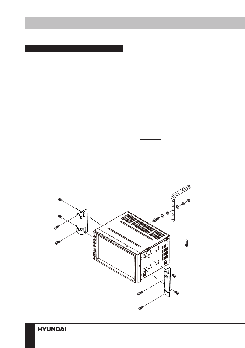
Mounting
• Connect the cable set and the antenna to
the vehicle’s electronics corresponding to the
connection table (see farther).
• Attach the mounting racks to the sides
and to the back of the unit, and fix them with
the screws.
• Insert the unit into the slot until the stop.
The unit then audibly snaps.
• Fasten the screws to fix the unit.
• The device is distinguished by a high
degree of output. During operation, this results
in a strong heat generation. Therefore no
cables or other parts may adjoin the device. If
their insulation melts, there is the risk of a short
circuit or fire.
• Removing: Turn off the device. Clamp off
the negative pole of the vehicle battery for the
duration of the disassembly. Unscrew the four
screws. Remove carefully the unit from the slot
and disconnect all wires. Make sure that no
vehicle cable can cause a short circuit after the
device has been unplugged.
4

Detachable control panel
• To attach the front panel, insert the upper
side of the panel first and make sure the
connection pins slide into the connection slots,
then press the lower part of the panel to the
unit until hear a click.
• Slant the front panel down. Press the
release lock (in the bottom of the front panel)
upward to release the front panel, and then
take out the front panel by pulling it downwards
and then towards you from the bottom. Once
the front panel is removed, the back plate will
close automatically after a few seconds and
the panel status indicator will blink.
The control panel can easily be
damaged by shocks. After removing it, place
it in a protective case and be careful not to
drop it or subject it to strong shocks. The rear
connector that connects the main unit and the
control panel is an extremely important part. Be
careful not to damage it by pressing on it with
fingernails, pens, screwdrivers, etc.
If the control panel is dirty, wipe off the
dirt with soft, dry cloth only. And use a cotton
swab soaked in isopropyl alcohol to clean the
socket on the back of the control panel.
Installation/Connection
Anti-theft system
The front panel of this unit can be stored in
the included protective case when not in used
and carried away when you leave the vehicle
to deter theft.
Switch off the power of the unit. Detach the
front panel, then put it to the protective case
and take it with you.
5
Installation/Connection
Connection
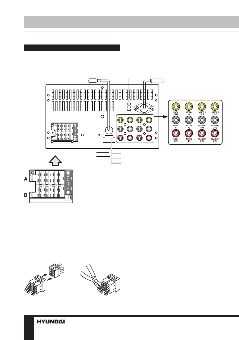
Connection diagram
TV Antenna
Reverse(purple-white)
Parking (green)
Connector A
1. Rear right speaker(+)/Purple
Rear right speaker(-)/Purple-Black
2.
3. Front right speaker(+)/Grey
4. Front right speaker(-)/Grey-Black
5. Front left speaker(+)/White
6. Front left speaker(-)/White-Black
7. Rear left speaker(+)/Green
8. Rear left speaker(-)/Green-Black
GPS antenna
Steering 1 (brown)
Steering 2A (white)
Steering 2B (grey)
Radio Antenna
Connector B
1. -
2. -
3. -
4. Battery 12V (+)/Yellow
5. Antenna power/Blue-White
Panel light/Orange-White
6.
7. ACC+/Red
8. Ground/Black
Using the ISO Connector
1. If your car is equipped with the ISO
connector, then connect the ISO connectors as
illustrated.
1. 2.
6
2. For connections without the ISO
connectors, check the wiring in the vehicle
carefully before connecting, incorrect connection
may cause serious damage to this unit.
Cut the connector, connect the colored leads
of the power cord to the car battery as shown
in the colour code table below for speaker and
power cable connections.
Installation/Connection
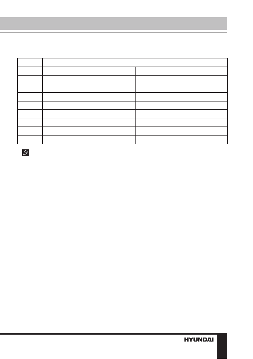
ISO connection table
Location Function
Connector A Connector B
1 Rear right speaker (+)/Purple 2 Rear right speaker (-)/Purple-Black 3 Front right speaker (+)/Grey 4 Front right speaker (-)/Grey-Black Battery 12V (+)/Yellow
5 Front left speaker (+)/White Antenna power/Blue-White
6 Front left speaker (-)/White-Black Panel light/Orange-White
7 Rear left speaker (+)/Green ACC+/Red
8 Rear left speaker (-)/Green-Black Ground/Black
Antenna power wire is intended for
power supply of the antenna and for remote
control of an additional amplifier.
7
Installation/Connection
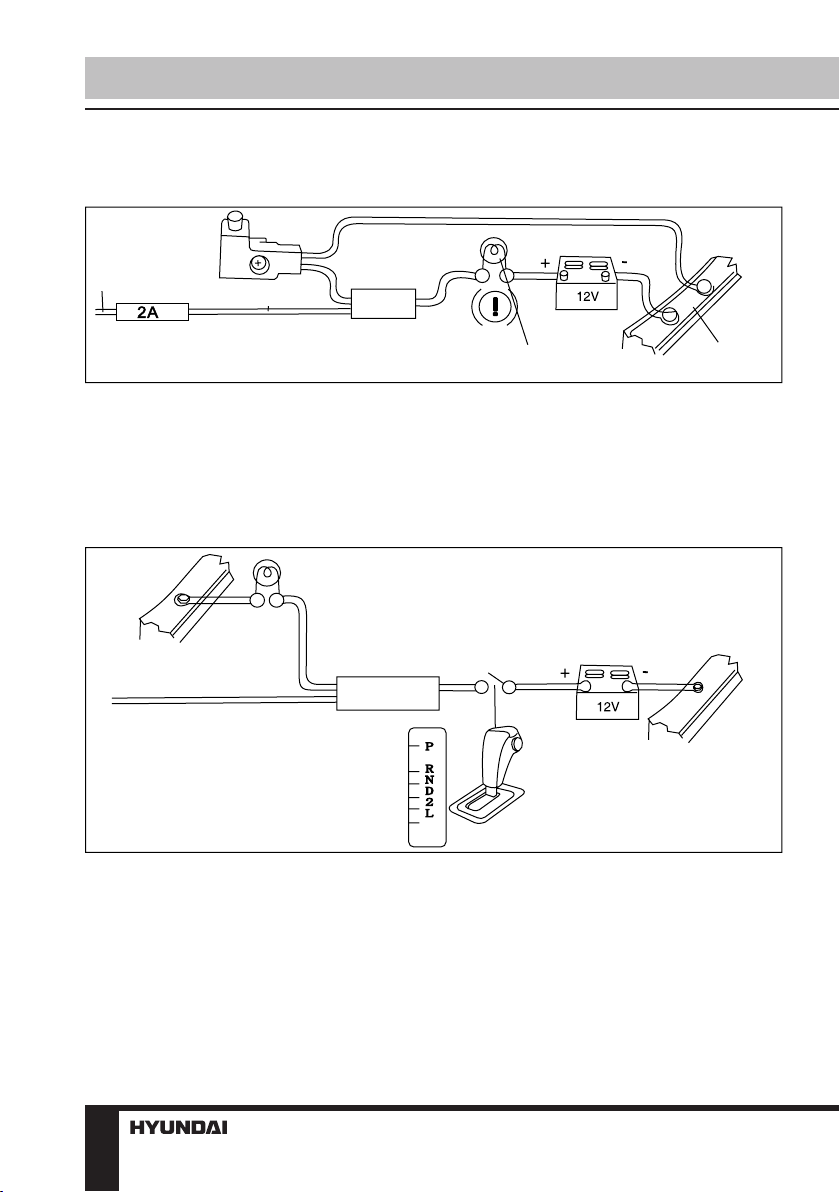
Parking wire connection
Parking brake lead
Green Wire
Brake light
Battery
Car frame
If Parking cable is connected to hand brake switch, the video display of the TFT monitor will be
controlled by driving status, system setup and input video sources. When the car is moving ahead,
if the video disc is played, the screen shows a warning message. The warning screen will prevent
the driver from watching images.
Reverse driving cable connection
Car frame
Purple-white wire
Rear view video camera lead
Reverse driving light
Gearbox
Battery
Car frame
If the rear view video camera is connected, the unit automatically switches to CAMERA source
during reverse driving. The unit returns to the original work mode after the reverse driving is done.
8
Control elements
Installation/Connection
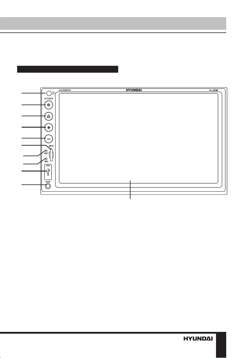
Front panel
1
G
2
3
4
5
6
7
8
9
10
1. IR-sensor 6. GPS data card slot
2. TFT/ON/OFF button 7. RESET button(hole)
3. HOME button 8. Microphone
4. VOL+ button 9. USB port
5. VOL- button 10. AUX-in
11. Display
11
9
Operation
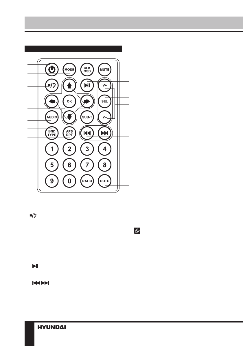
Remote controller (RC)
1
2
3
4
5
6
7
8
9
1. POWER button
2. MODE button
3. button
4. Cursor buttons
5. OK button
6. AUDIO button
7. BND/TYPE button
8. APS/RPT button
9. Number buttons
10. MUTE button
11. CLK/OSD button
12. button
13. SEL button
14. V+/- buttons
15. / buttons
16. RATIO button
17. GOTO button
10
11
12
13
14
15
16
17
Changing the battery
1. Press the catch and at the same time pull
out the battery tray.
2. Insert the 1 lithium battery, type CR2025
(3 V) battery with the stamped (+) mark facing
upward. Insert the battery tray into the remote
controller.
• Store the battery where children
cannot reach. If a child accidentally swallows
the battery, consult a doctor immediately.
• Do not recharge, short, disassemble or
heat the battery or dispose it in a fire.
• Do not expose or bring into contact the
battery with other metallic materials. Doing this
may cause the battery to give off heat, crack or
start a fire.
• When throwing away or saving the battery,
wrap it in tape and insulate; otherwise, the
battery may give off heat, crack or start a fire.
• Please direct the Remote controller to the
IR sensor of the front panel.
10
 Loading...