

Hyundai HSS-730, HSS-830, FD505, UFD515 Service Manual

HSS-730/830 & UFD505/515 SERVICE MANUAL HDT DVB SATELLITE STB
Page 1
HYUNDAI DIGITAL TECHNOLOGY
HSS-730/830 & UFD505/515 INTEGRATED SATELLITE
RECEIVER / DECODER
SERVICE MANUAL
REVISION A
DATE : January 10, 2002
2002 HDT co., Ltd
223-22, Sangdaewon-1dong, jungwon-gu,
Seongnam-si, kyoungki-do, Korea 462-807

HSS-730/830 & UFD505/515 SERVICE MANUAL HDT DVB SATELLITE STB
Page 2
Contents
HDT DIGITAL TECHNOLOGY… … … ..…..… … … … … … … … … … … … … … … … … … … … … … … … … … … ..1
HSS-730/830 & UFD505/515 INTEGRATED SETELLITE…… … … … … … … … … … … … … … … … … … … … … … ..1
RECEIVER / DECODER … … … … … … … … … … … … … … … … … …… … … … … … … … … … … … … … … … … … … .1
SERVICE MANUAL … … … … … … … … … … … … … … … … … … … … … … … ...…… … … … … … … … … … … … … … 1
REVISION A … … … … … … … … … … … … … … … … … … … … … … … … … … … … … … … … … … … … … … … … … … 1
1 Front Panel.. … … … … … … … … … … … … … … … … … … … … … … … … … … … … … … … … … … … … … … … … .5
1.1 Front Panel Buttons … … … … … … … … … … … … … … … … … … … .…… … … … … … … … … … … … … … … ..5
1.2 Front Panel Indicators … … … … … … … … … … … … … … … … … … … … … … … … … … … … … … … .…… …..5
2 Rear Panel … … … … … … … … … … … … … … … … … … … … … … … … … … … … … … … … … … … … … … … … … 6
2.1 Rear Panel Connectors … … … … … … … … … … … … … … … … … … … … … … … … … … … … … … … … … … ..6
3 Hardware … … … … … … … … … … … … … … … … … … … … … … … … … .…… … … … … … … … … … … … … … .…7
3.1 System Block Diagram … … … … … … … … … … … … … … … … … … … … … … … … … … … .……… … … … 7
3.2 Main Board Clock Diagram … … … … … … … … … … … … … … … … … … … … … … … … … … … … ..7
3.2.1 Clock Diagram for CI Model… … … … … … … … … … … … … … … … … … … … … … … … … …7
3.2.2 Clock Diagram for FTA Model… … … … … … … … … … … … … … … … … … … … … … … … ….7
3.3 Network Interface Module …… … … … … … … … … … … … … … … … … … … … … … … … … … … … … … … 9
3.3.1 NIM Module … … … … … … … … … … … … … … … … … … … … … … … … … … … …….……… … .9
3.3.1.1 Block Diagram … … … … … … … … … … … … … … … … … … … … … … … … … … .…… … … .9
3.3.1.2 Digital Network Interface Module Operating… … … … … … … … … … … … … … … … … … …9
3.3.1.3 Electrical Specification of Digital Tuner… … … … … … … … … … … … … … … … … .…… … .10
3.3.2 LNB Control … … … … … … … … … … … … … … … … … … … … … … … … … … … … … … … . …… .10
3.3.3 LNB Switching Control … … … … … … … … … … … … … … … … … … … … … … … … … … … … … 11
3.4 Software Download … … … … … … … … … … … … … … … … … … … … … … … … … … … … … … … ...12
3.4.1 RS-232 Cable Configuration… … … … … … … … … … … … … … … … … … … … … … … … … .12
3.4.2 Software Download with Serial Link Cable from PC … … … … … … … … … … … … … … …...…..12
3.4.3 Software Download with Serial Link Cable from other STB…… … … … … … … … … … ...……13
3.5 Output Interfaces … … … … … … … … … … … … … … … … … … … … … … … … … … … … … … … … … … … . … 14
3.5.1 TV and VCR/AUX Scart Configuration… … … … … … … … … … … … … … … … … … … … … … . ...14
3.5.2 TV Scart Connector Pin Configuration… … … … … … … … … … … … … … … … … … … … … ..…….15
3.5.3 VCR/AUX Scart Connector Pin Configuration… … … … … … … … … … … … … … … … ..……… … 15
3.5.4 RCA Cinch Connector … … … … … … … … … … … … … … … … … … … … … … … … ...…… … … … 16
3.5.5 RF Modulator (Option) … …… … … … … … … … … … … … … …...…… … … … … … ...……… … … .16
3.5.6 Power Connector Configuration… … … … … … … … … … … … … … … … … … … … ...…… … … … .16

HSS-730/830 & UFD505/515 SERVICE MANUAL HDT DVB SATELLITE STB
Page 3
3.5.7 Front Panel Connector Configuration… … … … … … … … … … … … … … … … … … … … … … … ...17
3.5.8 RS-232 Connector Configuration… … … … … … … … … … … … … … … … … … … … … … … … … ..17
4 Electrical Specifications … … … … … … … … … … … … … … … … … … … … … … … … … … … … … … … … … … ..18
4.1 Power Supply … … … … … … … … … … … … … … … … … … … … … … … … … … … … … … … … … … … … … 18
5 Trouble Shooting … … … … … … … … … … … … … … … … … … … … … … … … … … … .……… … … … … … … … .18
6 Schematic … … … … … … … … … … … … … … … … … … … … … … … … … … … … … .…… … … … … … … … … … 27
6.1 HSS-730/830 & UFD505/515 Circuit Diagram… … … … … … … … … … … … … … … … … … … … … … … ..27
6.2 Front Circuit Diagram… … … … … … … … … … … … … … … … … … … … … … … … … … … … … … … … … … 27
6.3 SMPS Circuit Diagram … … … … … … … … … … … … … … … … … … … … … … … … … … … … … … … … … 27
7 PCB Pattern … … … … … … … … … … … … … … … … … … … … … … … … … … … … … … … … … … … … … … … 27
7.1 HSS-730/830 & UFD505/515 Silk & PCB Pattern… … … … … … … … … … … … … … … … … … … … … … 27
7.2 HSS730/830 Front Silk & PCB pattern… … … … … … … … … … … … … … … … … … … … … … … … … … … 27
7.3 UFD505/515 Front Silk & PCB pattern… … … … … … … … … … … … … … … … … … … … … … … … … … … 27
8 Product Disassembly Diagram… … … … … … … … … … … … … … … … … … … … … … … … … … … … … … … 27
8.1 Product Disassembly Diagram for UFD505… … … … … … … … … … … … … … … … … … … … … … … … … 27
8.2 Product Disassembly Diagram for UFD515… … … … … … … … … … … … … … … … … … … … … … … … … 27
8.3 Product Disassembly Diagram for HSS-830… … … … … … … … … … … … … … ...…… … … … … … … … … 27
9 Part List … … … … … … … … … … … … … … … … … … … … … … … … … … … … … … … … … … … … … … … … 27
9.1 Part list for HSS-730/830 & UFD505/515… … … … … … … … … … … … … … … … … … … … … … … … … … 27
9.2 Part list for HSS-730/830 Front… … … … … … … … … … … … … … … … … … … … … … … … … … … … … … 27
9.3 Part list for UFD505/515 Front… … … … … … … … … … … … … … … … … … … … … … … … … … … … … … 27
9.4 Part list for SMPS … … … … … … … … … … … … … … … … … … … … … … … … … … … … … … … … … … … 27

HSS-730/830 & UFD505/515 SERVICE MANUAL HDT DVB SATELLITE STB
Page 4
USED FOR
HSS-730/830
UFT505/515
STB REPAIR
HSS-730/830 & UFD505/515 SERVICE MANUAL HDT DVB SATELLITE STB
Page 5
Introduction
The HDT DVB satellite STB is a receiver that is capable of receiving digital signals transmitted
through the satellite network. The services available on the HDT satellite STB includes
Digital television (including teletext services) & radio programs
1. Front Panel
The front panel is a secondary tool used to manipulate some of the STB functions. The number of
front panel buttons is limited compared to the RCU, but the user should be able to operate most
important STB functions via those buttons.
1.1. Front Panel Buttons for HSS-730/830 & UFD505/515
ž Standby On /Off Key
ž Menu Key
ž Select Key
ž Volume Up / Down Key
ž Channel Up / Down Key
The front panel buttons perform the same functions as the corresponding keys on the RCU. See the
User Manual for a description of the button functionality.
1.2. Front Panel Indicators
Standby/On indication LED This LED is illuminated red to indicate that the STB is in standby
mode, and off to indicate that the STB is in power on mode.
*RCU Key Received LED This LED is flashed orange to indicate that the STB is receiving
data from the RCU.
*TV/SAT Mode Indication LED This LED is used to indicate whether the STB receives the satellite
or terrestrial antenna input, and is illuminated green while
receiving terrestrial input, off while receiving the satellite input.
4 Digit Seven Segments These segments are used to display a channel number or any
messages.
* ‘RCU Key Received LED’ & ‘TV/SAT Mode Indication LED’ may be used in some derivative models.

HSS-730/830 & UFD505/515 SERVICE MANUAL HDT DVB SATELLITE STB
Page 6
2. Rear Panel
The rear panel provides all the connectors required to place the STB into the home video systems.
(HSS-730/830 & UFD505/515 Rear Panel)
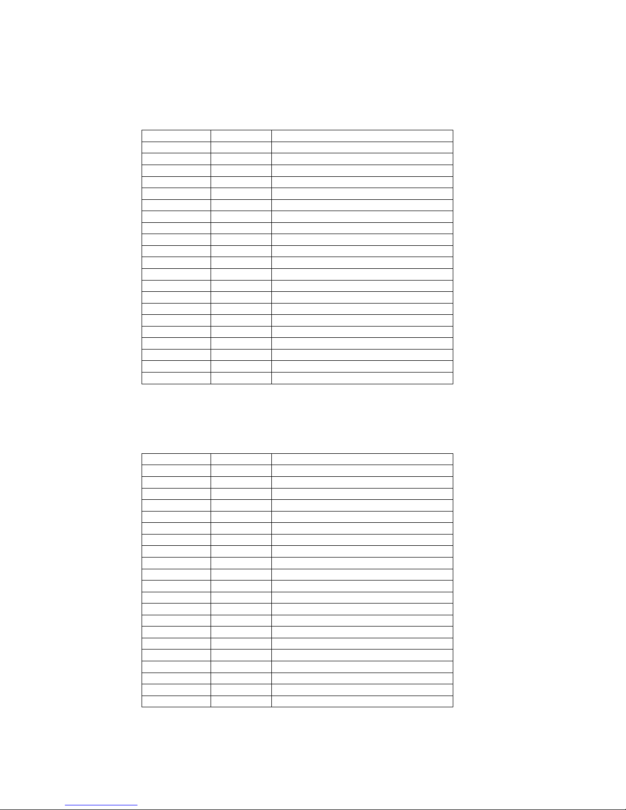
2.1. Rear Panel Connectors
Label Connector Function
SAT ANT IN IEC 169-24 female RF input from LNB to digital tuner
SAT ANT OUT IEC 169-24 female RF loop-through output from digital tuner
TV ANT IN IEC 169-2 female Input from terrestrial antenna
TV SCART SCART SCART output to TV
VCR/AUX SCART SCART SCART output to VCR/AUX
AUDIO L RCA cinch Left audio output
AUDIO R RCA cinch Right audio output
VIDEO RCA cinch Video output
SPDIF RCA cinch Digital audio output
RS-232C DB-9 female Low speed data output
※ Full option
HSS-730/830 & UFD505/515 SERVICE MANUAL HDT DVB SATELLITE STB
Page 7
3. Hardware
This section describes the entire architecture and an individual module of the STB hardware.
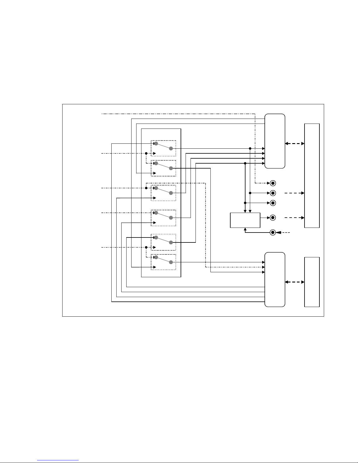
3.1. System Block Diagram
The hardware is modularly designed to support as many markets as possible while minimizing the
burden on developing the derivative hardware. This approach also enables the derivative hardware
to be quickly developed in order to meet a variety of user demands. The Block Diagram of page 8
depicts the System Block Diagram.
3.2. Main Board Clock Diagram
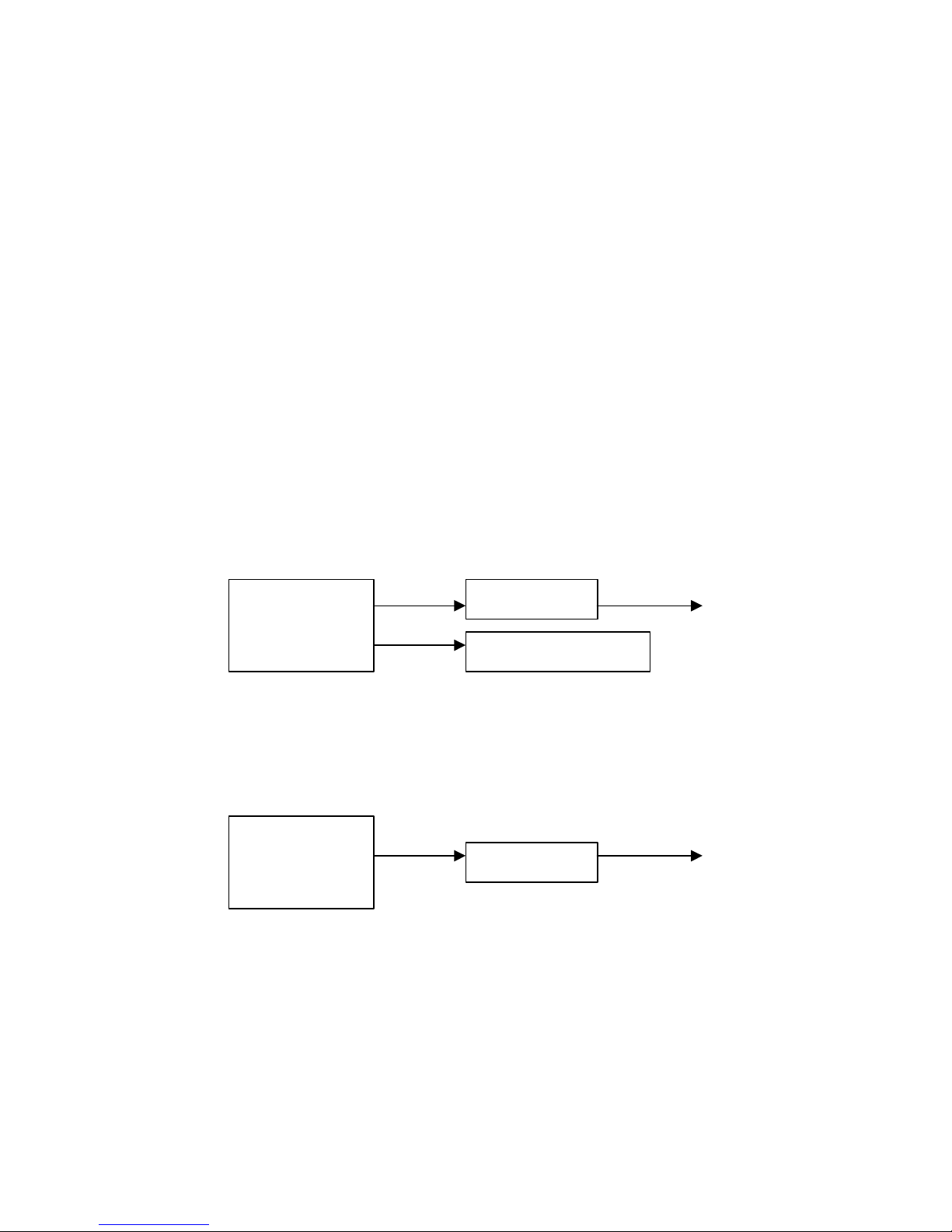
3.2.1. Clock Diagram for CI Model
l 27MHz System Clock
3.2.2. Clock Diagram for FTA Model
l 27MHz System Clock
VCXO 27Mhz
CIMAX /STV0700 Pin 35
121.5MHz
to SDRAM Pin 38
VCXO 27MHz
STi5518 Pin 120
121.5MHz
to SDRAM Pin 38
STi5518 Pin 120
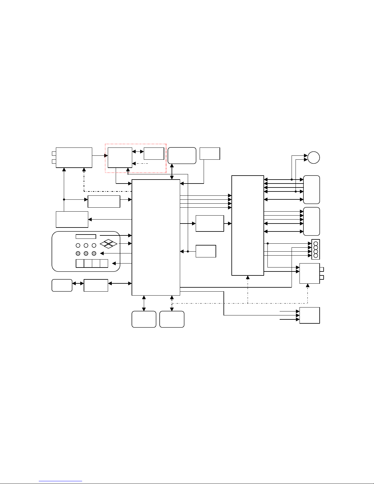
( HSS-730/830 & UFD505/515 Block Diagram )
STi5518BVB-X
CPU & MPEG
SYSTEM/VIDEO/AUDIO
DECODER
STV6412A
AUDIO/VIDEO
SWITCH
R,G,B
CVBS
Y
C
VCR/AUX
SCART
R/C
G
B
Y/CVBS
AUDIO L & R
CVBS
SPDIF
AUDIO L
AUDIO R
RCA
TV SCART
R/C
G
B
Y/CVBS
AUDIO L & R
S-VHS (option)
RF
Module
(HSM3052MPV)
CVBS
VCC
C
Y
FLASH
1M × 16bit
1EA
EEPROM
16Kbit
1EA
SDRAM
1M×16bit×4bank
1EA
16bit
I2C_1 (100kHz)
Audio DAC
WM8725ED
NIM
(TBMU30351IPB)
CIMAX
(STV0700)
I2C_1
(100kHz)
I2C_0 (100kHz)
LNB Control
Part
22kHz Detect
Part
IR receiver
Buttons (7)
LED (3)
4 Digit
7-Segment
8 8 8 8
Front Panel
RS232
MAX232
UART
(115kbps)
SKEW
SKEW
AUDIO
0/12V
JTAG
VCXO
27MHz
PCMCIA
2 slot
□ □
□ □
(Part of CI Model)
HSS-730/830 & UFD505/515 SERVICE MANUAL HDT D
VB SATELLITE
Page 8
HSS-730/830 & UFD505/515 SERVICE MANUAL HDT DVB SATELLITE STB
Page 9
3.3. Network Interface Module
3.3.1. NIM Module
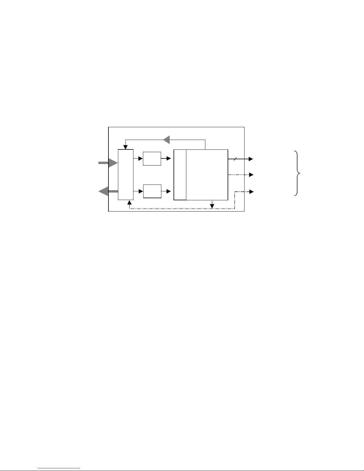
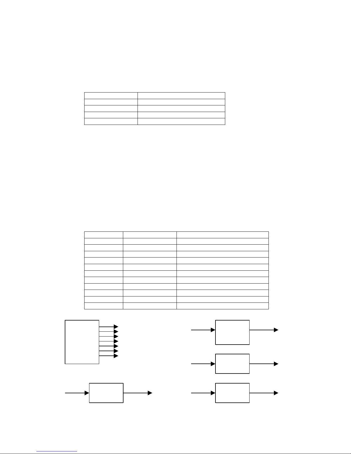
3.3.1.1. Block Diagram
The NIM module has digital tuner as depicted in the following figure.
3.3.1.2. Digital Network Interface Module Operating
The satellite RF input signal (1st IF) is connected to the tuner. The tuner down-converts the RF
signal to ZERO IF signal, and then generates the analog base band I(In-phase) and Q(Quadrature)
signals containing a QPSK modulated digital data. After passing the LPF and A/D converter, these
signals are demodulated by the QPSK demodulator into a digital data stream.
The satellite signal is relatively noisy and this may produce a high bit-error rate at the demodulator
output. The high demodulator bit-error rate will produce errors in the MPEG decoder that will in
turn lead to unsatisfactory audio/video quality. The FEC is needed to reduce the bit-error rate to an
acceptable level (bit-error rate of 10
-11
). The FEC used a Reed-Solomon decoder to reduce a burst
error and a viterbi decoder to correct a bit error.
RF Loop-through
Digital Tuner Module
Digital Tuner
LPF
LPF
A/D Converter
QPSK
Demodulator
FEC
I
Q
AGC
Satellite
RF In
Transport
Stream
Control
I2C_0 100kHz
8
HSS-730 & UFD505 : STi5518BVB-X
HSS-830 & UFD515 : STV0700
HSS-730/830 & UFD505/515 SERVICE MANUAL HDT DVB SATELLITE STB
Page 10
3.3.1.3. Electrical Specification of Digital Tuner
Impedance
75 Ω
Return Loss > 8dB
Frequency Range 950 to 2150 MHz
Signal Level -65 to -25 dBm
AFC Range + - 3MHz
Connector IEC 169-24 female (F-type) and male (for loop-through)
Phase Noise
10 kHz
100 kHz
< -70 dBc/Hz
< -90 dBc/Hz
Synthesizer Step Size PSK & BPSK (Compliant to DVB-S)
Nyquist Shaping Filter 35% square root raised cosine
Symbol Rate 2 up to 45 Msps
Inner Code Convolitional (K=7)
FEC Code Rate 1/2,2/3,3/4,5/6,7/8. Automatically detected
Interleaving Factor I = 12
Outer code RS (204,188,T = 8)
Spectral Inversion Automatically detected
3.3.2. LNB Control
The LNB is powered through the center conductor of the RF coaxial cable connecting the LNB to
the STB. The polarization is switched by varying the power supply voltage of the LNB. In addition,
a 22kHz tone is used to switch the LNB between the low frequency band and the high frequency
band. The high frequency band is selected when the 22kHz is present.
The horizontal and vertical polarizations have different voltage ranges as shown in the below table.
Current 500mA max. (Short circuit protected)
Vertical Polarization Voltage 13 to 14.5 V
Horizontal Polarization Voltage 17 to 19 V
Software Controlled LNB ON/OFF Supported
The characteristics of the 22kHz tone is as follows:
Duty Cycle
50% ± 10%
Frequency
22 kHz ± 4 kHz
Amplitude
0.6V (± 0.2V)
Rising and Falling Time
10 µs ± 5 µs
Software Controlled Tone ON/OFF Supported
HSS-730/830 & UFD505/515 SERVICE MANUAL HDT DVB SATELLITE STB
Page 11
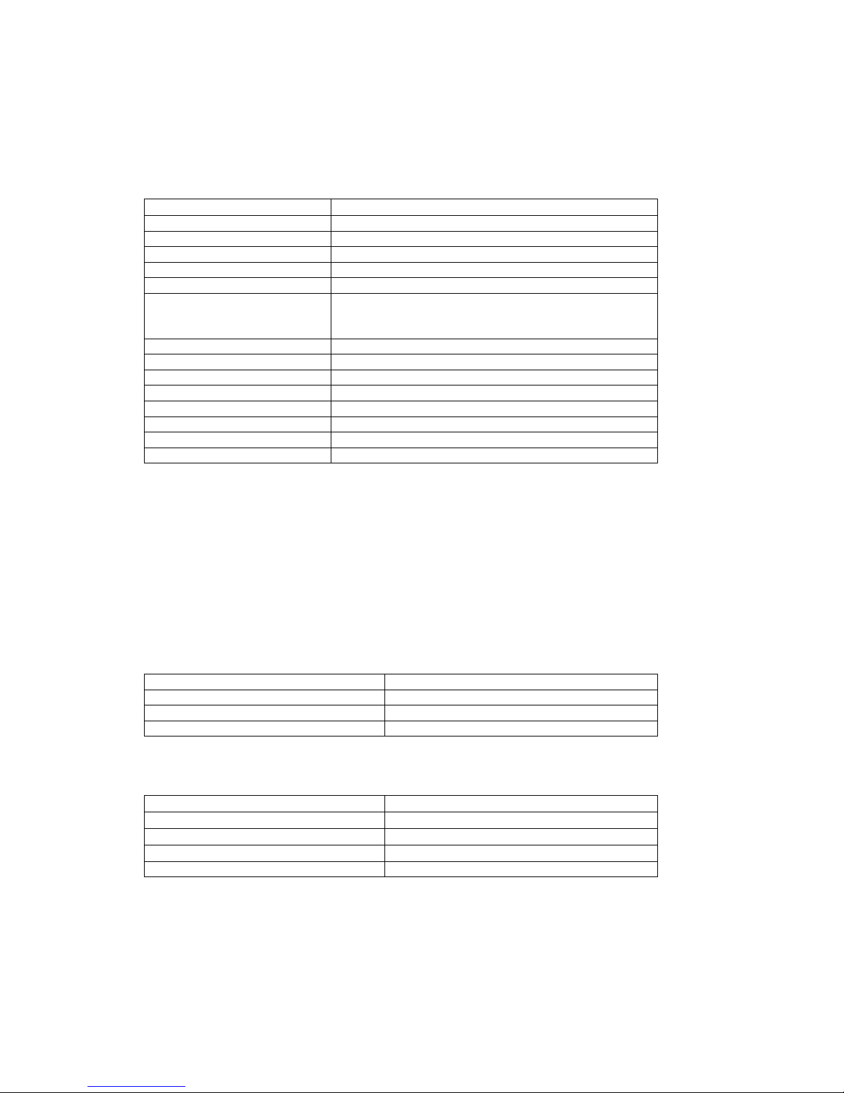
The following figure is an example of universal LNB.
3.3.3. LNB Switching Control
As shown in the below figure, the STB supports the following LNB switching methods
DiSEqC 1.2 (including the SMATV mode) Compliant (over DiSEqC 1.2 in future).
The switching type controlled by 14/18V DC.
The switching type controlled by 22kHz Tone.
The STB can Generates a DiSEqC command by modulating the 22kHz signal.
10.70 ~ 11.70 GHz
and
11.70 ~ 12.75 GHz
LO
LO
Hor
Ver
RF Amp
14/18V
Switch
RF Amp
9.75 GHz
10.60 GHz
IF Amp
0/22kHz
Switch
Polarization Selection
High/Low Band
Selection
STB
Satellite Dish
HSS-730/830 & UFD505/515 SERVICE MANUAL HDT DVB SATELLITE STB
Page 12
3.4. Software Download
The resident software boots up the STB, downloads the entire new software as needed, and tests the
hardware integrity of the STB. These software modules are stored in non-volatile memory so that
these should not be erased during a power outrage or other catastrophic events.
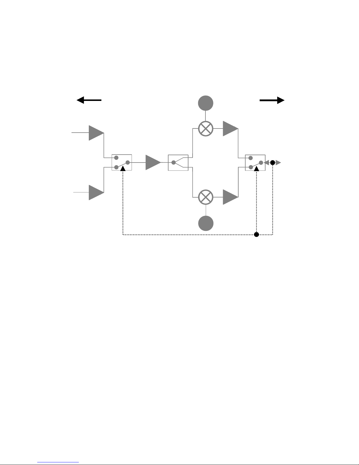
3.4.1. RS-232 Cable Configuration
3.4.2. Software Download with Serial Link Cable form PC
As the STB boots up, the download module is the first to run. It starts by waiting for receipt of an
acknowledgement message on the serial interface indicating that the download is to be performed.
If this message is received within a given second, the module is waiting for commands from the
host PC.
This download module loads an entire STB software image into the STB via the serial interface.
The software image is downloaded into the RAM for verification and then is written to FLASH.
When the module completes a download, it resets and restarted the STB automatically.
Procedure to download the software
First, connect the serial link cable between the PC and STB and make sure that the STB is in the standby or
power off mode.
①
Execute download program (dn.exe), select correct directory and file in your PC
Download file have two types, one is main program, other is channel data.
②
Select correct serial port and command type (‘Download’ is default).
③
Click button ‘Execute ’ then the data is transferred from PC to the STB via the serial interface. Turn on the
STB power.
④
The STB will display ‘SUCC’ when the download is complete.
STB
RS-232 Port
2
3
5
2
3
5
PC
RS-232 Port
Female Female

HSS-730/830 & UFD505/515 SERVICE MANUAL HDT DVB SATELLITE STB
Page 13
3.4.3. Software Download with Serial Link Cable from other STB
Procedure to download the software
First, connect the serial link cable between the master STB and slave STB and make sure that the STB is in the
standby or power off mode.
①
After the master STB turn on, push select key and volume down key simultaneously for downloading
main Program
If master STB is ready, FND display ‘ - - - - ’ in Front panel.
FND is not display ‘ - - - -’, try again
②
The slave STB turn on and then wait
③
The master, slave STB will display ‘SUCC’ all when the download is complete.
④
After the master STB turn on, push select key and volume up key simultaneously for downloading
channel data.
⑤
The slave STB turn on and then wait
⑥ The master, slave STB will display ‘SUCC’ all when the download is complete
HSS-730/830 & UFD505/515 SERVICE MANUAL HDT DVB SATELLITE STB
Page 14
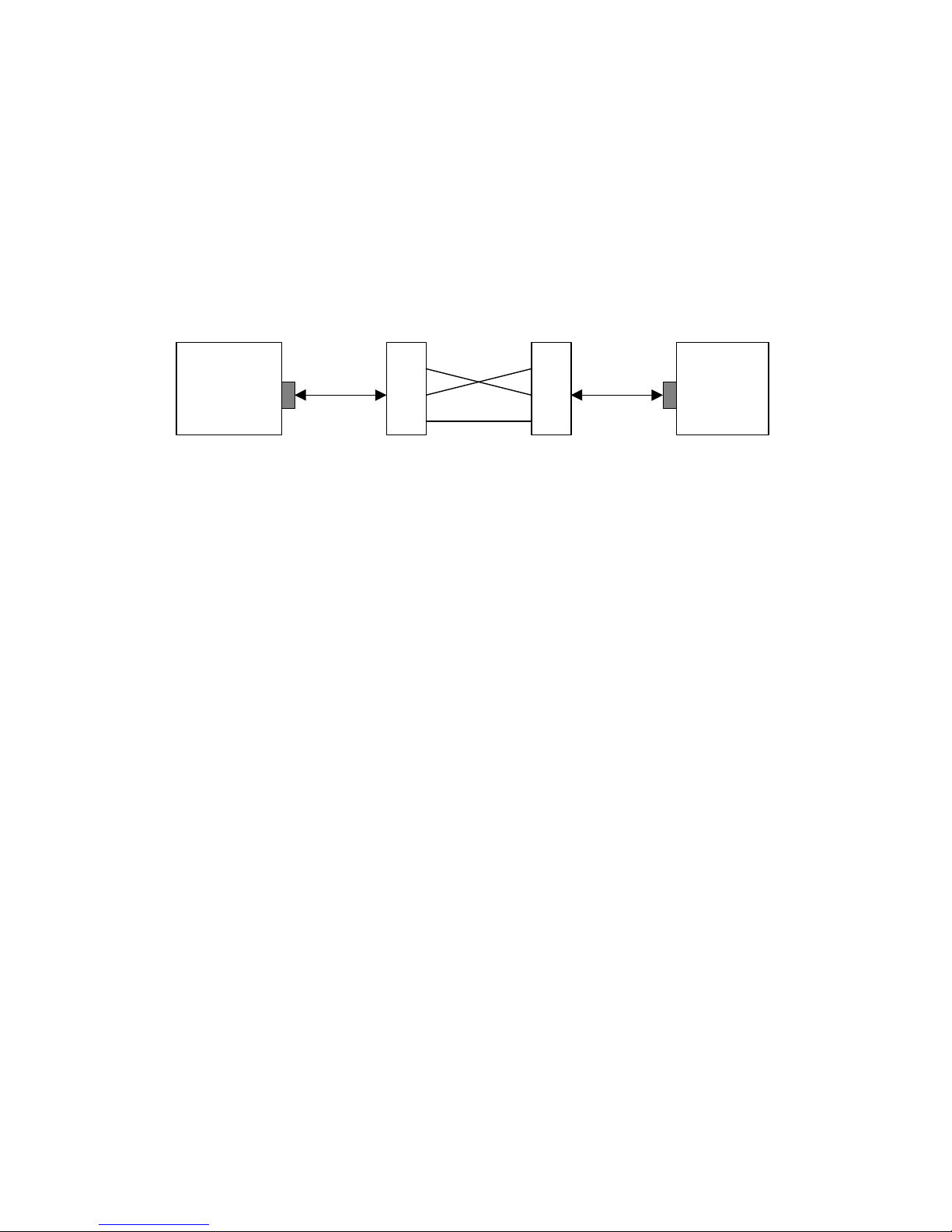
3.5. Output Interfaces
3.5.1. TV and VCR/AUX Scart Configuration
The STB presents the audio and video data to the user in a variety of formats. The following figure
describes the logical wiring of the STB outputs.
If the STB is in the power-on mode, the user controls the output source selection for the VCR/AUX
Scart, and the voltage on pin 8 of the VCR/AUX Scart is ignored.
If the STB is in the standby mode, it detects the voltage on pin 8 of the VCR/AUX Scart. If the
voltage is present, the STB automatically switches the output source to the VCR/AUX Scart and
generates the appropriate voltage on pin 8 of the TV Scart.
MPEG CVBS
TV SCART CVBS
TV SCART
MPEG Y/C
MPEG AUDIO
TV SCART AUDIO
MPEG RGB
VCR/AUX SCART
SPDIF
STV6412
CVBS
Y/C
RGB
AUDIO
AUDIO
MPEG Y/C
CVBS
VCR/AUX SCART AUDIO
VCR/AUX SCART
VCR/AUX SCART
VCR/AUX SCART
RCA Cinch
RF
Modulator
Output
IED 169-2
Antena
RF Input
Television
VCR or
Analog SVR
HSS-730/830 & UFD505/515 SERVICE MANUAL HDT DVB SATELLITE STB
Page 15
3.5.2. TV Scart Connector Pin Configuration
PIN number Signal name Description
1 AOUTR Audio right output to TV
2 AINR Audio right input from TV
3 AOUTL Audio left output to TV
4 RTN5 Ground
5 RTN1 Ground
6 AINL Audio left input from TV
7 BLUE B output to TV
8 MODE 0/6/12V output (4:3 or 16:9 mode select)
9 RTN2 Ground
10 RSV1 Not connected
11 GREEN G output to TV
12 RSV2 Not connected
13 RTN3 Ground
14 RTN6 Not connected
15 RED R or C output to TV
16 BLK 0/1~3V output (RGB or CVBS,Y/C select)
17 RTN4 Ground
18 RTN7 Ground
19 VOUT CVBS or Y output to TV
20 VIN CVBS input from TV
21 GND Ground
3.5.3. VCR/AUX Scart Connector Pin Configuration
PIN number Signal name Description
1 AOUTR Audio right output to VCR/AUX
2 AINR Audio right output from VCR/AUX
3 AOUTL Audio left output to VCR/AUX
4 RTN5 Ground
5 RTN1 Ground
6 AINL Audio left output form VCR/AUX
7 BLUE B input from VCR/AUX
8 MODE 0/6/12V input (4:3 or 16:9 mode select)
9 RTN2 Ground
10 RSV1 Not connected
11 GREEN G input from VCR/AUX
12 RSV2 Not connected
13 RTN3 Ground
14 RTN6 Not connected
15 RED R input form VCR/AUX
16 BLK 0/1~3V output (RGB or CVBS,Y/C select)
17 RTN4 Ground
18 RTN7 Ground
19 VOUT CVBS video output to VCR/AUX
20 VIN CVBS video output from VCR/AUX
21 GND Ground
HSS-730/830 & UFD505/515 SERVICE MANUAL HDT DVB SATELLITE STB
Page 16
3.5.4. RCA Cinch Connector
The MPEG stereo audio and CVBS video and digital audio(SPDIF) are available through four
cinch connectors.
Color Description
Yellow Video (CVBS)
White Audio left
Red Audio right
Black Digital Audio (SPDIF)
3.5.5. RF Modulator (Option)
The RF modulator takes the mono audio and CVBS video internally generated by the STB, converts
them to an UHF channel selected by the user and then adds this channel to all terrestrial channels
coming in from the terrestrial antenna. That is, the RF modulator outputs all terrestrial channels
where the STB generated CVBS and mono audio becomes one channel within the UHF channels 21
to 69 range.
The input connector is an IEC 169-2 female, and the output is an IEC-169-2 male connector.
3.5.6. Power Connector Configuration
PIN number Name Description
1 Standby 5V 5V in standby mode
2 Standby 3.3V 3.3V in standby mode
3 VCC Main 5V
4 GND Ground
5 Power 8V 8V
6 Power 12V Analog 12V
7 Power 22V LNB 22V
8 Power 30V 30V
9 GND Ground
10 Power control Main Power control 0:0ff, 5V:on
11 GND Ground
SMPS
STBY5V
STBY3V3
VCC5V
ANALOG12V
POWER8V
LNB22V
POWER30V
Regulator
AS1583
(Diode
SBYV27-200)
STBY3V3 STBY2V5
Regulator
7805A
POWER8V NIM5V
Regulator
LM317M
LNB22V 14/18V VCC5V
Regulator
AME1117
POWER3V3
HSS-730/830 & UFD505/515 SERVICE MANUAL HDT DVB SATELLITE STB
Page 17
3.5.7. Front Panel Connector Configuration
PIN number Signal Description
1 Digit1 FND digit1 select
2 Digit2 FND digit2 select
3 Digit3 FND digit3 select
4 Digit4 FND digit4 select
5 Standby5V Power 5V
6 Digit_data1 FND digit data1
7 Digit_data2 FND digit data2
8 Digit_data3 FND digit data3
9 Digit_data4 FND digit data4
10 Digit_data5 FND digit data5
11 Digit_data6 FND digit data6
12 Digit_data7 FND digit data7
13 Digit_data8 FND digit data8
14 Standby5V Power 5V
15 Row0 Front Key Row data0
16 Row1 Front Key Row data1
17 Row2 Front Key Row data2
18 Col0 Front Key Column data0
19 Col1 Front Key Column data1
20 Col2 Front Key Column data2
21 IR_RCV Remocon sensor data
22 TV_DBS_LED Control for TV/DBS LED
23 Remote_LED Remocon sensor operating for LED
24 Pw_on_LED Control for standby Power on/off
25 GND Ground
26 GND Ground
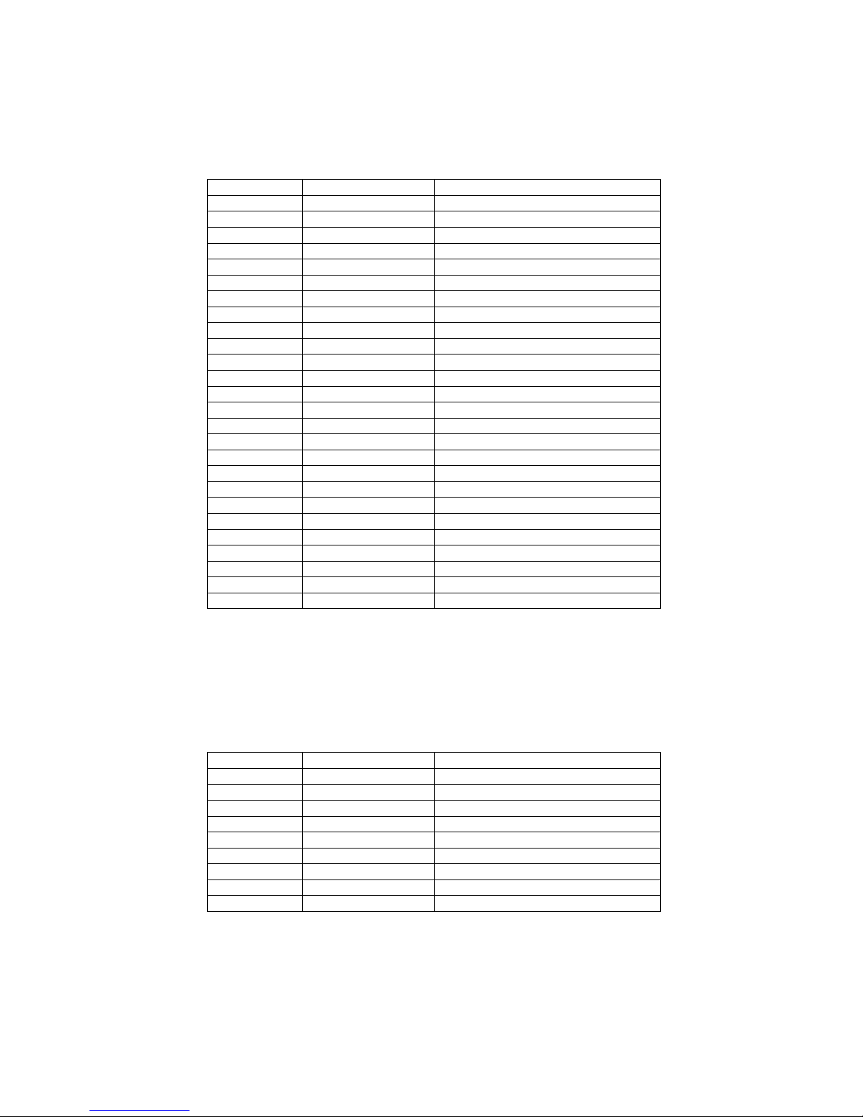
3.5.8. RS-232 Connector Configuration
A RS-232C serial interface is provided on a 9-pin D-type female connector. This interface may be
used to connect an STB to the PC for an entire software downloading and error monitoring.
Pin Number Signal Signal Description
1 Not Connected Carrier Detect
2 RXD Receive Data
3 TXD Transmit Data
4 Not Connected Data Terminal Ready
5 GND Ground
6 Not Connected Data Set Ready
7 Not Connected Clear To Send
8 Not Connected Request To Send
9 Not Connected Ring Indicator
 Loading...