

Hyundai U125S, U125J, U125P Installation & Operation Manual
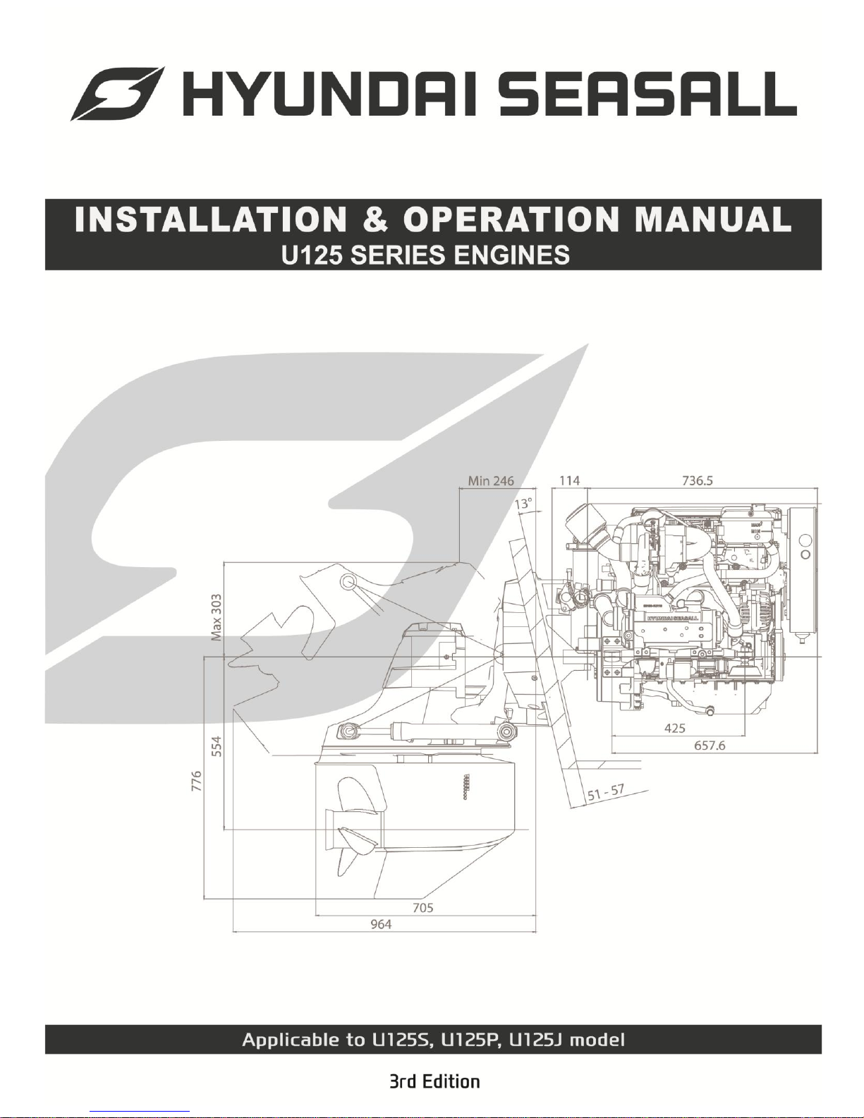
INSTALLATION & OPERATION MANUAL
U125 Series Engines
-1-
TABLE OF CONTENTS
ABOUT THIS MANUAL …………………………………………………….…………………
SAFETY PRECAUTIONS……………………………………………………………………
APPROXIMATE CONVERSIONS FROM STANDARD……………………………………..
CHAPTER 1 ENGINE OVERVIEW ………………………………………………………..
1. ENGINE COMPONENTS …………………………………………………
2. ENGINE HANGER……………..……………………………………………
3. ENGINE IDENTIFICATION ………………………………………….…..
4. SCHEMATIC DIAGRAM OF COMMON RAIL DIESEL ENGINE ……
5. TECHNICAL DATA ……………………………………………...…..……
6. PERFORMANCE CURVE ……………………………………………..…
7. BELT LAYOUT & ENGINE DIMENSIONS……….……………………
CHAPTER 2 ENGINE MOUNT SYSTEM .……………………………………………….
1. PREPARING THE ENGINE INSTALLATION….……………....….…..
1.1 CHECK THE MOUNT HOLE………………………………….
2. BELLHOUSING FIXING………………………………………………….
3. ASSEMBLING ENGINE MOUNTS……………………..………….……
CHAPTER 3 COOLING & EXHAUST SYSTEM …………………………………….……
1. SCHEMATIC DIAGRAM OF ENGINE COOLING CIRCUIT ……….…
2. SEAWATER FLOW………………………………………….……….……
2.1 WATER PICKUP …………………………………..……….……
2.2 SEAWATER STRAINER ………………………..……….…….
2.3 SEAWATER PUMP ……………………………..………………
2.4 CHECKING SEA WATER PUMP & IMPELLER …….……..
2.5 SEA WATER DRAIN …………………………..………………..
3. ENGINE COOLANT FLOW………..…………………………….………
3.1 ENGINE COOLANT……………………..…………………..…
3.2 REMOVING AIR BUBBLE ………..….….……………….…...
3.3 CABIN HEATER CONNECTION.…..…….……………..……
4. EXHAUST SYSTEM ………………………………………………………
CHAPTER 4 FUEL SYSTEM ………………………………………………………….……
1. FUEL FLOW………. ……………………………….……..………………
2. LOW PRESSURE FUEL LINE …………………....…………….…………
3. ACCELERATION SENSOR AND CONTROL LEVER …………………
4. RECOMMENDED FUEL QUALITY ………………....…………….………
5. DRAINING WATER FROM FUEL FILTER ………………………………
CHAPTER 5 AIR INTAKE SYSTEM …………………………………………………………
1. ENGINE AIR CONSUMPTION….………………………….……………
2. ENGINE ROOM VENTILATION……………………………….…..………
3. AIR FILTER MAINTENANCE………………………………………………
CHAPTER 6 LUBRICATION SYSTEM ………………………………………………….…
1. ENGINE OIL LEVEL CHECKS ………………………………….………
2. RECOMMENDED OIL QUALITY ………………………….…….....……
3. ENGINE OIL EXTACTION PUMP ………………………..………..……
4. OIL FILTER REPLACEMENT …………………………………….………
3
4
5
6
6
7
8
9
10
11
13
16
16
16
17
17
18
18
19
19
19
20
21
22
23
23
25
25
26
27
28
28
29
30
30
31
31
31
32
33
33
33
34
34
INSTALLATION & OPERATION MANUAL
U125 Series Engines
-2-
TABLE OF CONTENTS
CHAPTER 7 ELECTRICAL SYSTEM ……………………………………………………
1. BATTERY CABLE CONNECTIONS …………………………….......…
2. BATTERY CHECKS ………………………………………………….…
3. FUSE AND RELAY ………………………………………………….……
CHAPTER 8 INSTRUMENT SYSTEM ……………………...…………………..…………
1. INSTRUMENTS CONNECTION …………..……………….….……...…
2. CUT-OUT FOR GAUGE…………………………………………………
3. CUT-OUT FOR EOI SYSTEM …………………..………….……….……
4. SEASLINK PRODUCT COMPONENTS………………….……..………
5. INSTALLATION OF SEASLINK DONGLE……………….……………..
CHAPTER 9 EOI SYSTEM …………………………………………..…………………..
1. OVERVIEW OF EOI SYSTEM ……………………..…………………..…
1.1 INFORMATION LCD ITEM ……………………...……………...…
1.2 SWITCHES ………………………………………......…………..….
1.3 ALARM LAMPS ………………………………………..………...…
2. EOI CONNECTIONS ………………………………………......……..…
3. EOI PIN ASSIGNMENT …………..………………………………........
4. NEUTRAL SWITCH AND DUAL EOI CONNECTION …………….…
5. TRI
M WIRING CONNECTION DIAGRAM ………………………...…
6. G-SCAN……………………………………………………………..…….
7. ALARM AND DTC(DIAGNOSIS TROUBLE CODE) ………………….
7.1 ALARM AND DTC(DIAGNOSIS TROUBLE CODE) …………….
7.2 DTC(DIAGNOSIS TROUBLE CODE) LIST………….……………
CHAPTER 10 ANTI CORROSION SYSTEM …………………………………………….
CHAPTER 11 ENGINE OPERATION …………………………………………………..….
1. ENGINE ON/OFF ……………………………………………………….…
2. ENGINE BRAKE IN………………………………………………………
3. EMERGENCY STOP …………………..…………………………….……
CHAPTER 12 ENGINE STORAGE …………………………………………………..……
WINTER STORAGE…………………………………….………………….
CHAPTER 13 MAINTENANCE …………………………………………………………..…
1. THE INITIAL RUNNING CHECK..……………………………….………
2. MAINTENANCE SCHEDULE …………………………………..………
3. STERNDRIVE & TRANSMISSION MAINTENANCE SCHEDULE ….
4. MAINTENANCE LOG……………………………………………………
CHAPTER 14 TROUBLESHOOTING GUIDE ……………………………………………
CHAPTER 15 WARRANTY …………………………………………………………………
WARRANTY REGISTRATION CARD ……………………………..………
35
35
36
37
39
39
42
42
43
44
45
45
45
46
46
47
48
50
51
52
53
53
56
61
62
62
63
64
65
66
67
67
68
69
70
71
73
78
INSTALLATION & OPERATION MANUAL
U125 Series Engines
-3-
ABOUT THIS MANUAL
This engine installation and operation manual is provided as guidance for the installation of
Hyundai SeasAll engine in a boat, and to describe engine operation. Its purpose is to provide
technical information to aid in performing an effective engine installation so as to achieve both
maximum performance and service life. For information on installation, operation and maintenance
of the ZF Marine Transmissions and Sterndrive Bravo Models, please see the separate booklets
included in the original packaging of your Hyundai SeasAll purchase.
Hyundai SeasAll is committed to making clear and accurate information available for those who
maintain, own and repair the U125 Series engines. Hyundai SeasAll values your input regarding
revisions and additional information for our manuals.
WARNING
DEVIATION FROM INSTALLATION INSTRUCTIONS AND OPERATION
GUIDELINES MAY LEAD TO PERSONAL INJURY OR DEATH TO
OPERATORS AND NEARBY PERSONNEL.
CAUTION
DEVIATION FROM INSTALLATION INSTRUCTIONS AND OPERATION
GUIDELINES MAY LEAD TO IMPROPER OPERATION, DAM AGE OR
DESTRUCTION OF THE ENGINE.
The manufacturer is not liable for any damages or losses caused by faulty installation, wrong
handling of the equipment and/or deficient maintenance.
The operator is responsible for the correct and safe operation of the engine and safety of its
occupants and general public.
It is strongly recommended that each operator read and understand this manual before
installing and operating the engine.
This manual as well as safety labels posted on the engine use the following safety alerts to
draw your attention to special safety instructions that should be followed.

INSTALLATION & OPERATION MANUAL
U125 Series Engines
-4-
SAFETY PRECAUTIONS
HOT SURFACES AND FLUIDS
• There is always a risk of burns when working
with a hot engine. Be aware of hot parts like
the turbocharger system, the exhaust system,
hot coolant hoses, etc. Wait until the engine
is fully cool to do inspection and maintenance.
REFUELING
• Refuel only after the engine completely stops.
• Use only the recommended fuel. The wrong
grade of fuel can cause operating problems,
can cause the engine to stop and can cause
engine damage.
• Pay special attention to safe practices when
refueling.
PAINT DAMAGE
• Damage of the engine or parts paint during
maintenance and inspection can cause
corrosion. Any damage must be repainted
after inspection and maintenance.
WELDING ON ENGINE
• Welding directly on the engine block can
cause damage to the engine control systems.
The ECU and related electronic devices must
be disconnected and removed if unavoidable
welding is needed.
.
• Read and understand this operator’s manual
as well as other information supplied by
Hyundai SeasAll for safe use of these
products. Be sure to check your engine
regularly.
• Do not use the engine for a purpose other
than what is intended by Hyundai SeasAll.
Do not modify the performance of the
supplied engine without the express
permission of Hyundai SeasAll. This can be
dangerous, can shorten the life of your
engine and can invalidate your warranty.
• Original and genuine parts supplied from
Hyundai SeasAll must be used for
inspections and maintenance. Hyundai
SeasAll does not guarantee any damage
caused by the use of imitation parts.
• Engine inspection and maintenance should
be carried out by properly trained and factory
approved service engineers.
• The engine should be inspected if the
electronic engine control unit shuts down the
engine.
INSTALLATION & OPERATION MANUAL
U125 Series Engines
-5-
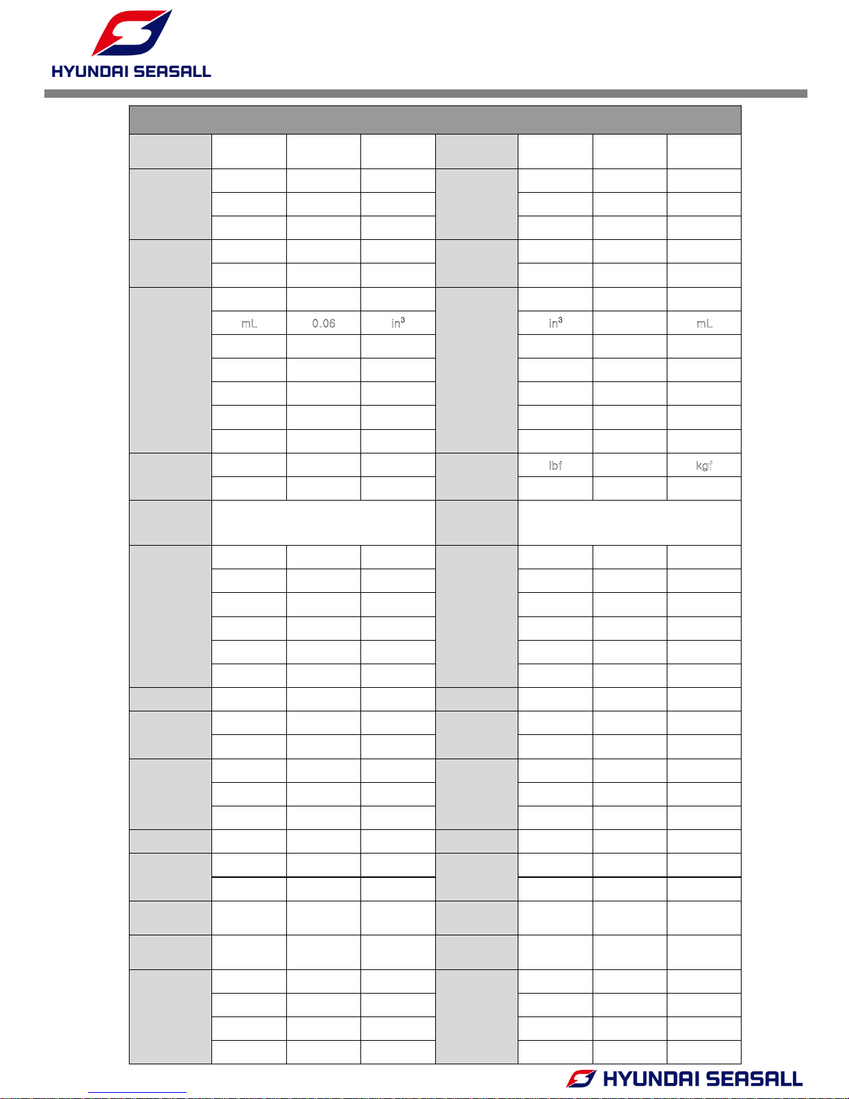
APPROXIMATE CONVERSIONS FROM STANDARD
SYMBOL
MULTIPLY
BY
SYMBOL
SYMBOL
MULTIPLY
BY
SYMBOL
LENGTH
mm 0.039 inch
LENGTH
inch 25.4 mm
cm 0.4 inch inch 2.54 cm
m 3.28 ft ft 0.3048 m
AREA
mm
2
0.0016 in2
AREA
in2 645.2 mm2
m
2
10.764 ft2 ft2 0.093 m2
VOLUME
cm
3
0.061 in³
VOLUME
in³ 16.388 cm3
mL
0.06 in3 in3
16
mL
Ldm
3
61.023 in³ in³ 0.016 Ldm3
Ldm
3
0.22 imp.gallon imp.gallon 4.545 Ldm3
Ldm
3
0.264 U.S.gallon U.S.gallon 3.785 Ldm3
m
3
0.76 yd3 yd3 1.3 m3
m
3
35.315 ft³ ft³ 0.028 m3
FORCE
kgf 2.204 lbf
FORCE
lbf
0.453
kgf
N 0.224 lbf lbf 4.448 N
TEMP.
o
F=9/5x℃+32 TEMP.
o
C=5/9x(℉-32)
PRESSURE
Bar 14.5 psi
PRESSURE
psi 0.068 Bar
MPa 145 psi psi 0.0068 MPa
Pa 0.102 mmWc mmWc 9.807 Pa
Pa 0.004 inWc inWc 249.098 Pa
KPa 4 inWc inWc 0.249 KPa
mWg 39.37 inWc inWc 0.025 mWg
TORQUE Nm 0.738 lbf ft TORQUE lbf ft 1.356 Nm
WEIGHT
kg 2.205 lb
WEIGHT
lb 0.454 kg
kg 35.273 oz oz 0.028 kg
WORK
kJ/kWh 0.43 BTU/lb
WORK
BTU/lb 2.326 kJ/kWh
MJ/kg 430 BTU/lb BTU/lb 0.0023 MJ/kg
kJ/kg 0.24 Kcal/kg Kcal/kg 4.184 kJ/kg
ENERGY kJ/kg 0.697 BTU/hph ENERGY BTU/hph 1.435 kJ/kg
FUEL
CONSUMP.
g/kWh 0.736 g/hph
FUEL
CONSUMP.
g/hph 1.36 g/kWh
g/kWh 0.0016 lb/hph lb/hph 616.78 g/kWh
FLOW RATE
(GAS)
m
3
/h 0.588 ft³/min
FLOW RATE
(GAS)
ft³/min 1.699 m3/h
FLOW RATE
(LIQUID)
m
3
/h 4.403 US gal/min
FLOW RATE
(LIQUID)
US gal/min 0.2271 m3/h
SPEED
m/s 3.281 ft/s
SPEED
ft/s 0.3048 m/s
kph 0.539 knots knots 1.852 kph
mph 0.869 knots knots 1.1508 mph
kph 0.62 mph mph 1.61 kph
INSTALLATION & OPERATION MANUAL
U125 Series Engines
-6-
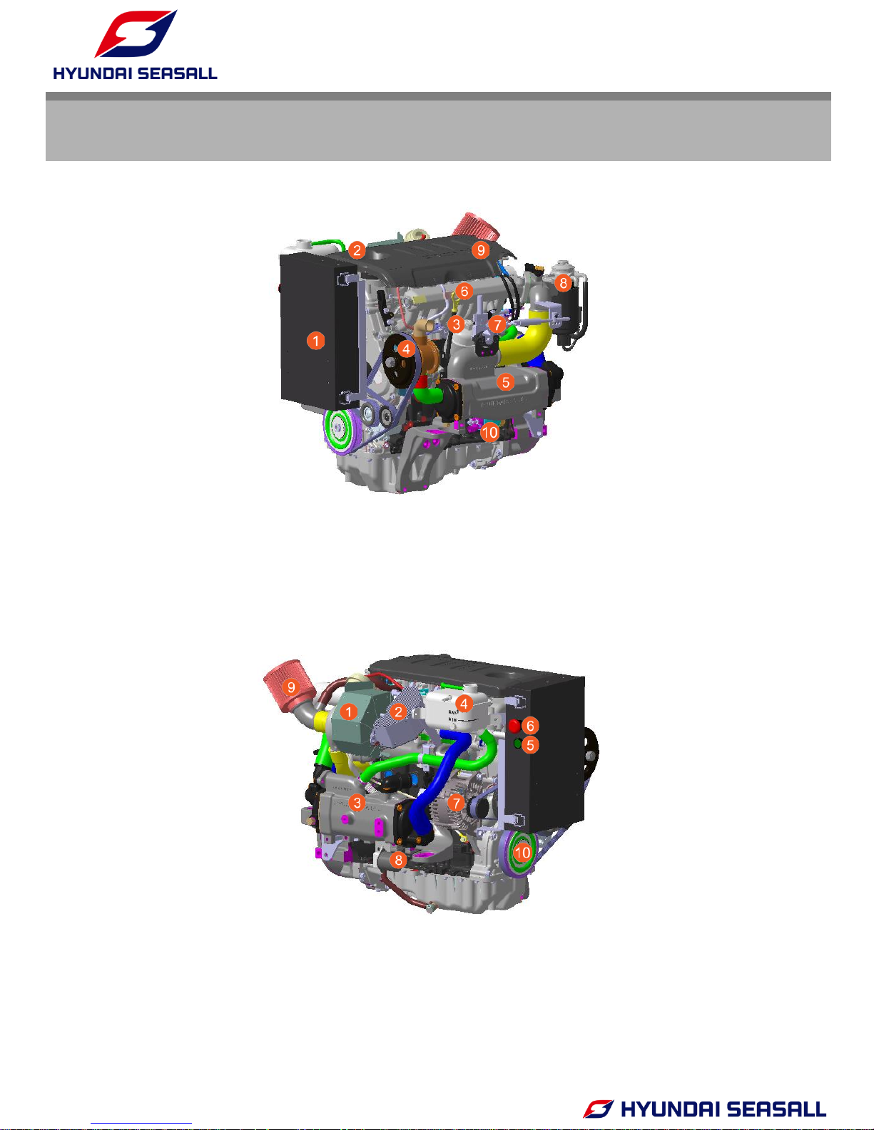
CHAPTER 1
ENGINE OVERVIEW
1. ECU Box
2. Engine Oil Cap
3. Engine Oil Filter
4. Seawater Pump
5. Intercooler
6. Engine Oil Gauge
7. Acceleration Lever Sensor
8. Fuel Filter
9. Eng. Cover
10.Starter
1. Turbo Heat Protector
2. Exhaust Elbow Heat protector
3. Heat Exchanger
4. Expansion Tank
5. Engine Oil Extraction Button
6. Engine Emergency Stop Button
7. Alternator
8. Oil Extraction Pump
9. Air filter
10. Crank Pulley
1.ENGINE COMPONENTS
INSTALLATION & OPERATION MANUAL
U125 Series Engines
- 7 -
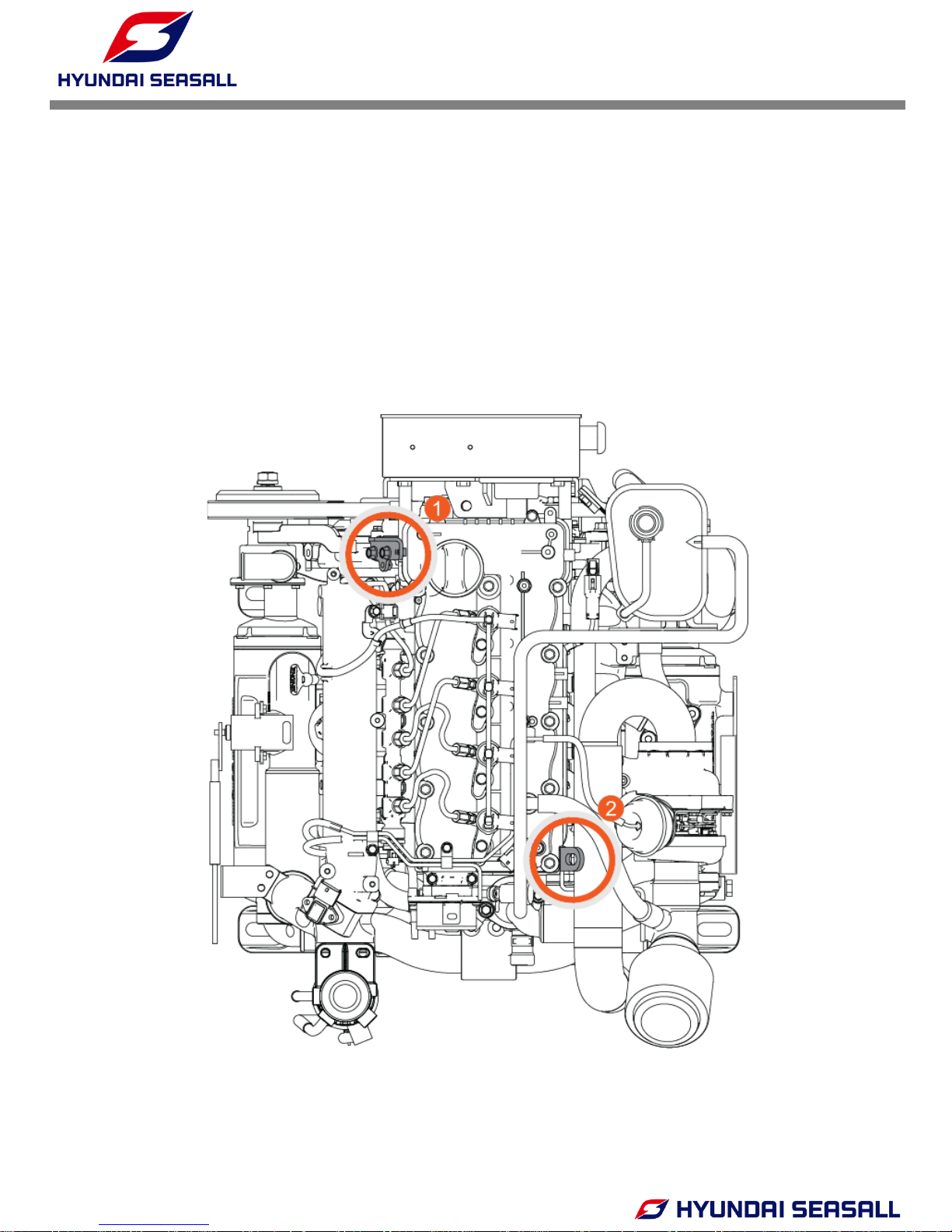
• To lift the engine, first remove the engine cover. You will find two engine hanger (see
figure)
• To avoid engine damage, take care that engine lift chains or belts do not hit or touch
surrounding parts during engine lifting.
2. ENGINE HANGER
INSTALLATION & OPERATION MANUAL
U125 Series Engines
-8-
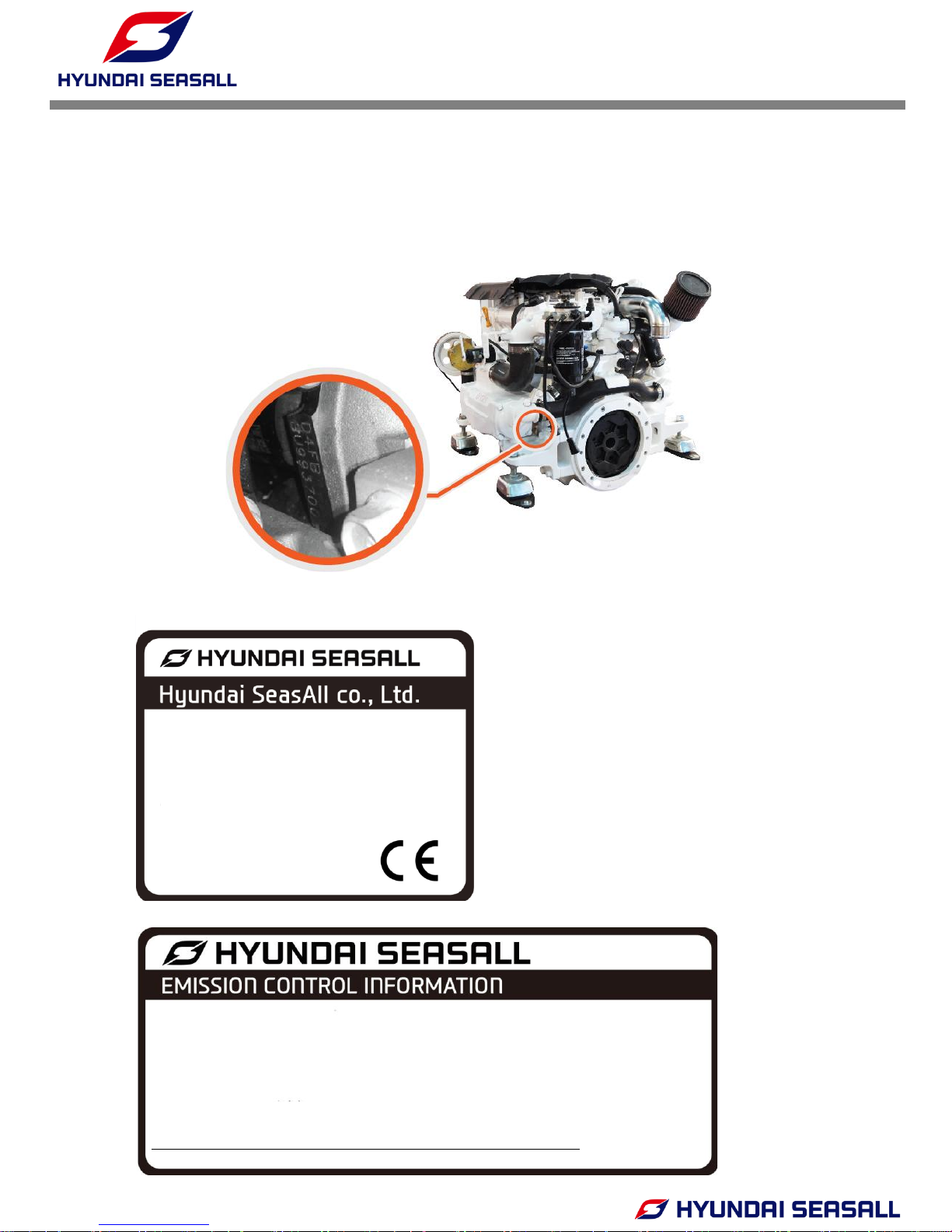
SERIAL NUMBER ON THE ENGINE BLOCK
Engine identification is affixed to the engine block and the ECU box (see figure).
3. ENGINE IDENTIFICATION
• ENGINE NAME PLATE
Engine Family
Engine Type
Engine Serial No.
Rated Power @Speed
No. Of Cylinder
Bore x Stroke
D4FB
U125X
XXXXXXXX
125PS @ 4000rpm
4
77.2mm x 84.5mm
EPA Engine Family FHYSN2.94HYS IMO Engine Family FHYSN2.94HYS
Max Power 93 (kW) Power Density 58.8 (kW/L)
Displacement / Cylinder 0.4 (L/cyl) Date of Manufacture MM/YYYY
Application Recreational Useful Life 1,000 hours or 10 years
Emission Standard THC+NOx : 5.8 (g/kWh) PM : 0.15 (g/kWh) CO : 5.0 (g/kWh)
EMISSION CONTROL SYSTEM
THIS ENGINE IS EQUIPPED WITH ELECTRONIC DIRECT FUEL INJECTION SYSTEM. THIS
ENGINE IS CERTIFIED TO OPERATE ON DIESEL
THIS MARINE ENGINE COMPLIES WITH U.S. EPA REGULATION FOR 2015
INSTALLATION & OPERATION MANUAL
U125 Series Engines
-9-
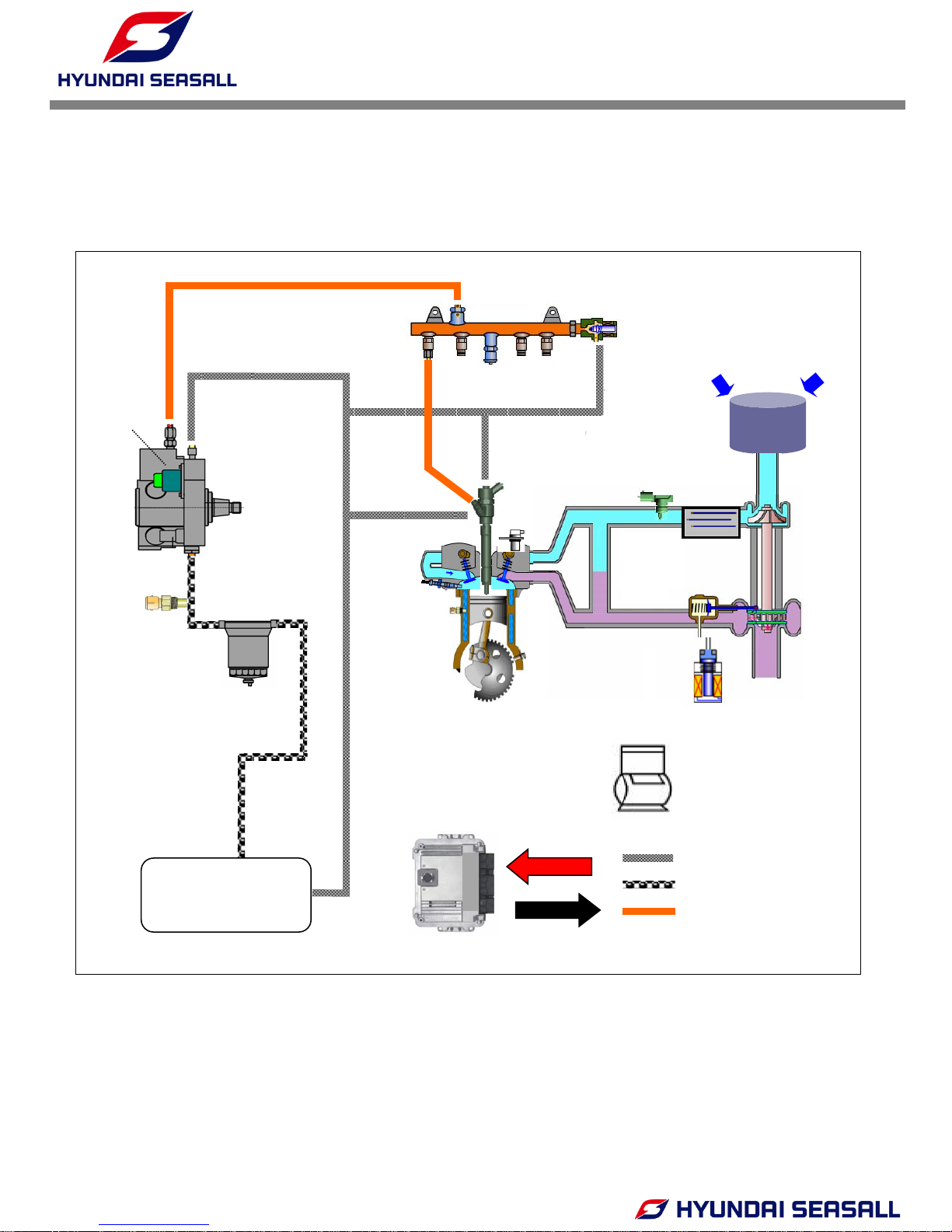
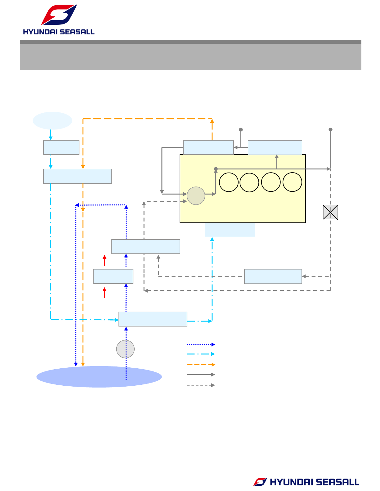
4. SCHEMATIC DIAGRAM OF COMMON RAIL DIESEL ENGINE
ECU
Fuel feed (low pressure)
Fuel feed (High pressure)
Fuel return
Fuel temperature
sensor
Glow
Plug
Crankshaft Position
sensor
VGT
actuator
Water sensor
in fuel
Injector
Intercooler
High pressure
pump
Main fuel filter
Air filter
Pump pressure
regulator valve
Acc. Position
sensor
Boost pressure
sensor &
Air Temp.
sensor
Sensor
Actuator
Fuel Tank
Feed
Return
Return
Return
VGT
Rail pressure
regulator valve
Return
Coolant
Temp.
Sensor
Vacuum
modulator
Common rail
Rail pressure
Sensor
Cam Position
sensor
INSTALLATION & OPERATION MANUAL
U125 Series Engines
-10-
5. TECHNICAL DATA
Engine type
U125S U125P U125J
4-stroke, 16-valve
After-cooled, direct-injection, water cooling
Output ps (kW) 125ps (93)
rpm at full load 4000
Cylinders In-line 4
Ignition sequence 1-3-4-2
Displacement [cm
3
] 1,582
Bore [mm] 77.2
Stroke [mm] 84.5
Compression ratio 17.3 : 1
Max. torque [kgm]
@ speed [rpm]
26.3 23.5
2000 3700
Injection system Common rail direct injection
Diesel fuel at least CN 51 as per DIN EN 590
Intake air pressure (abs. bar)
@ speed [rpm]
2.5 bar @ 4000 rpm
Coolant quantity (liter) 5.5
Coolant cap opening pressure (bar) 1.1
Engine oil (liter) 5.7
Engine oil pressure (bar)
2~3 at 1800rpm, 100 ℃(oil temp.)
Exhaust gas pressure (kPa) Max. 45
Alternator [A] 130
Engine diagnosis Yes
Weight (kg) 220
Battery capacity (AH) 12V, 150AH recommended
Thermostat opening temp. (℃)
85 (starting to open), 95 (fully open)
Idle rpm warmed up (rev/min) 730
Permissible eng. oil temp (℃)
135
Permissible eng. coolant temp (℃)
105
Fuel Consumption (Rated) (l/hr) @ 27.3 @ 4000 rpm
Propulsion system Sterndrive Shaftdrive Waterjet
INSTALLATION & OPERATION MANUAL
U125 Series Engines
-11-
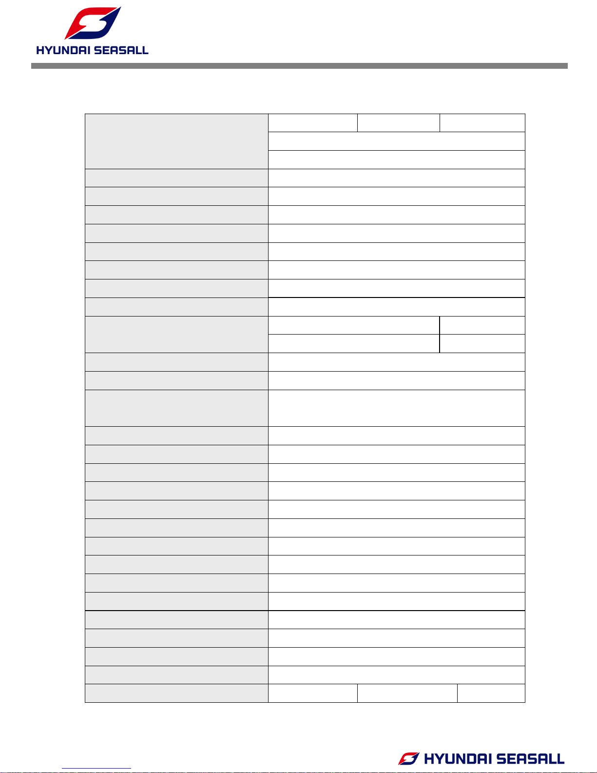
6. PERFORMANCE CURVE
U125S & U125P MODEL
*F.C : Fuel Consumption
0
25
50
75
100
125
150
0
5
10
15
20
25
30
1000 1500 2000 2500 3000 3500 4000 4500
Power (ps)
Torque (kgm)
Torque
0
5
10
15
20
25
30
1000 1500 2000 2500 3000 3500 4000 4500
F.C (L/h)
Engine Speed (rpm)
INSTALLATION & OPERATION MANUAL
U125 Series Engines
-12-
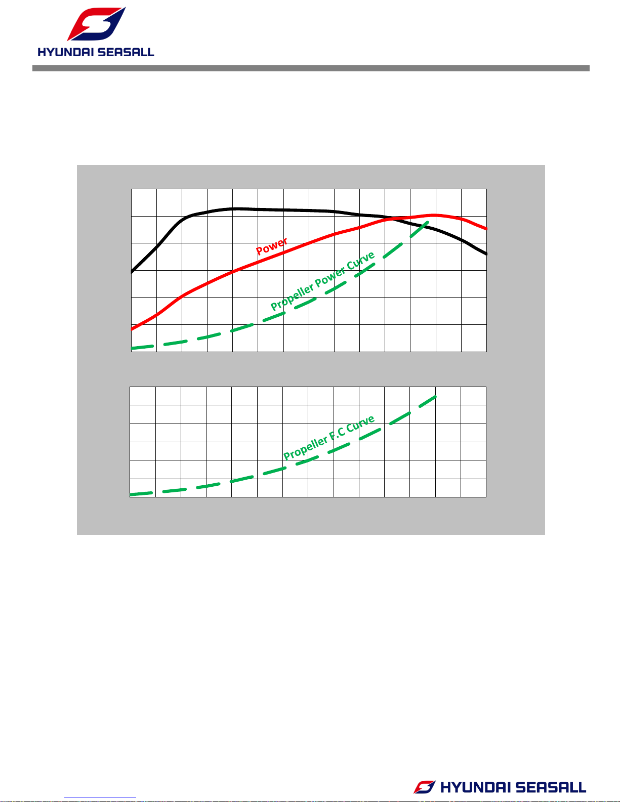
U125J MODEL
*F.C : Fuel Consumption
0
25
50
75
100
125
150
0
5
10
15
20
25
30
1000 1500 2000 2500 3000 3500 4000 4500
Power(ps)
Torque (kgm)
0
5
10
15
20
25
30
1000 1500 2000 2500 3000 3500 4000 4500
F.C (L/h)
Engine Speed (rpm)

INSTALLATION & OPERATION MANUAL
U125 Series Engines
-13-
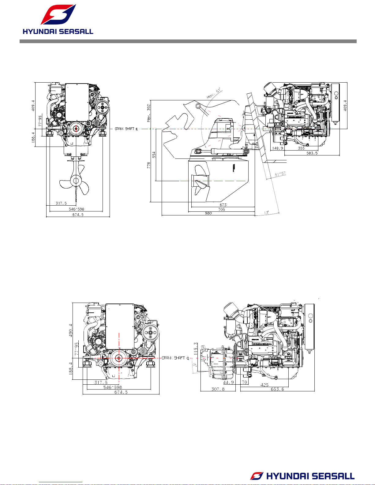
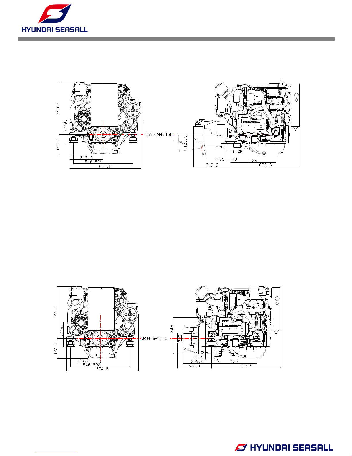
7. BELT LAYOUT & ENGINE DIMENSIONS
Bobtail
Side view [for sterndrive]
Side view [for shaftdrive] Side view [for waterjet with bearing housing]
V-RIBBED BELT LAYOUT
Front view
INSTALLATION & OPERATION MANUAL
U125 Series Engines
-14-
Side view
ZF 25 A
Front view
Side view
MerCruiser Bravo One X Diesel
Front view
INSTALLATION & OPERATION MANUAL
U125 Series Engines
-15-
ZF 45 A
Front view
Side view
ZF 45 C
Front view
Side view
INSTALLATION & OPERATION MANUAL
U125 Series Engines
-16-
CHAPTER 2
ENGINE MOUNT SYSTEM
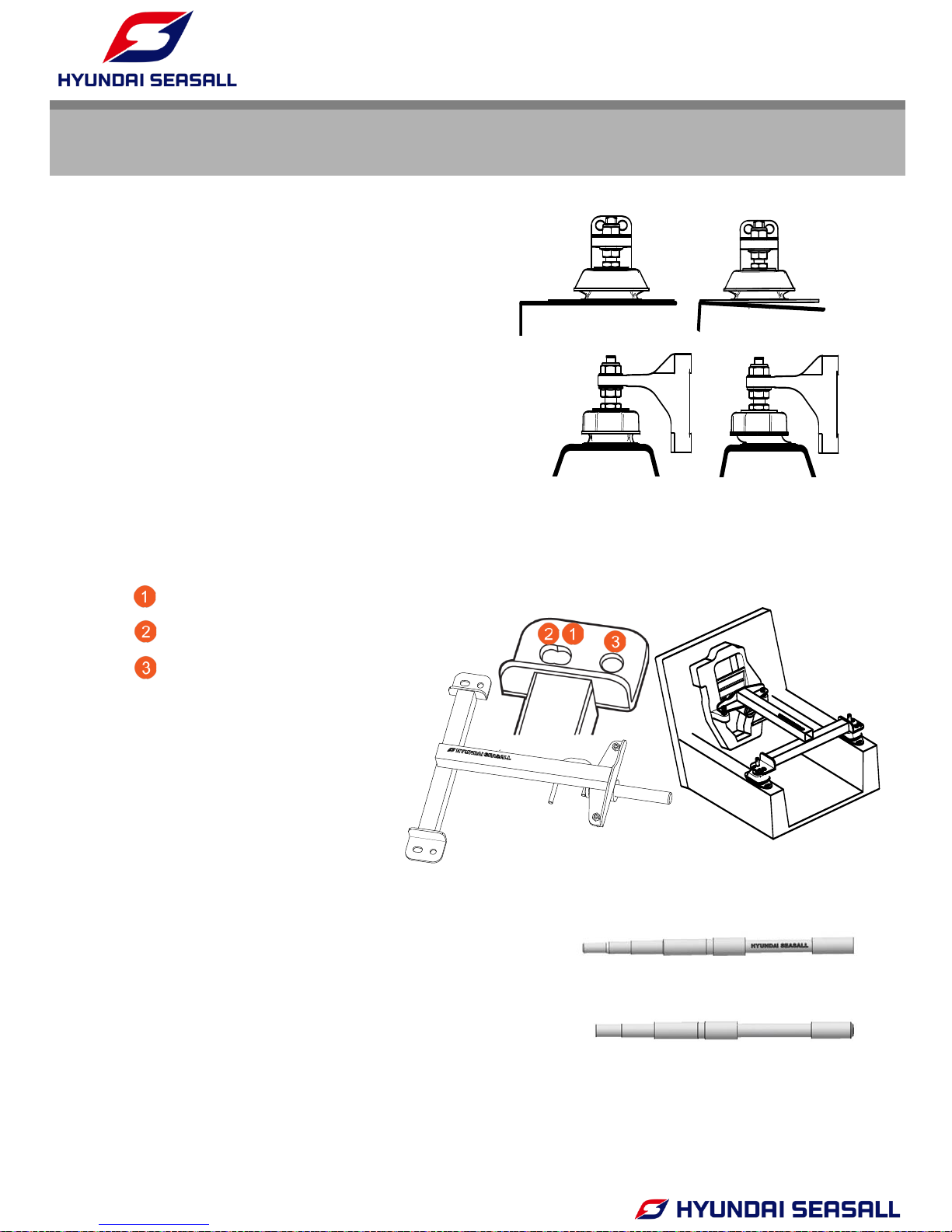
1.1 CHECK THE MOUNT HOLE
Mount hole for U125 model
Mount hole for D170 and D150 model
Mount hole for S250 and S270 model
-. It is essential that the engine bed is perfectly flat
before using the engine mount tool.
-. Make sure that the rubber engine mounts are
installed so that no pre-load or side forces occur
when the engine has been installed and aligned
with the stern drive
<Check the position of
the Engine Mounts >
1. PREPARING THE ENGINE INSTALLATION
<Engine mount tool>
(X) (O)
(X)
(O)
Hyundai-SeasAll alignment tool(5 Step)
MerCruiser alignment tool(4 Step)
(O)
(X)
-. Engine installation must be done by a qualified
technician. Hyundai SeasAll engines must be aligned
using the genuine Hyundai SeasAll alignment tool
Otherwise the drive coupler will be damaged.
INSTALLATION & OPERATION MANUAL
U125 Series Engines
-17-
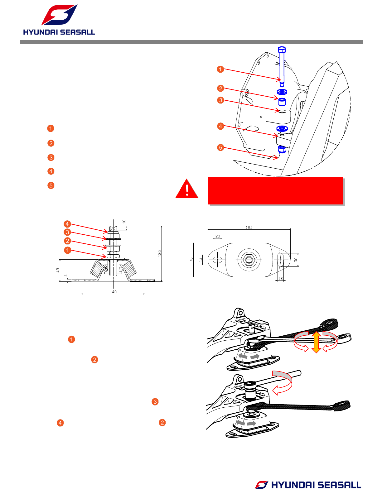
1) To prevent twisting the engine mount during
engine alignment, use a spanner on the lower
nut ( ) to keep the bolt from turning while
adjusting the engine height by turning the
middle nut ( ). Adjust the engine height until
the Hyundai SeasAll alignment tool can be
properly inserted.
2) After alignment, place washer ( ) on top of
engine support bracket and tighten lock nut
( )while keeping the middle nut ( ) from
turning with a spanner.
-. Assemble exhaust pipe after tightening the
mounting bolts between bell housing and
transom plate. Use the following parts:
Mounting Bolt
Washer
Spacer
Fiber Washer
Nut
3. ASSEMBLING ENGINE MOUNTS
2. BELLHOUSING FIXING
WARNING
DON’T USE THE SPRING WASHER.
IF YOU USE SPRING WASHER, THE PROBLEM OF
ENGINE ALIGNMENT CAN BE OCCURRED.
INSTALLATION & OPERATION MANUAL
U125 Series Engines
-18-
CHAPTER 3
COOLING & EXHAUST SYSTEM
1. SCHEMATIC DIAGRAM OF ENGINE COOLING CIRCUIT
IN-MANIFOLD
Pc
COOLANT
PUMP
INTERCOOLER
OIL COOLER
TURBO CHARGER
AIR FILTER
SEA WATER
PUMP
THERMOSTAT
OIL
SEAWATER
INTAKE AIR
EXHAUST AIR
COOLANT ( THERMOSTAT CLOSED & OPENED )
COOLANT (THERMOSTAT OPENED )
SEAWATER
EXPANSION TANK
AIR
ENG.OIL COOLER
HEAT EXCHANGER
EX-MANIFOLD
Ps
CABIN HEATER
CONNECTOR
INSTALLATION & OPERATION MANUAL
U125 Series Engines
-19-
Water strainer ← Water valve ← Water pickup
↓
① Seawater pump
↓
② Intercooler
↓
③ Transmission oil cooler
↓
④ Heat exchanger
↓
⑤ Exhaust elbow
↓
Sea water
2. SEAWATER FLOW – OPEN COOLING CIRCUIT
2.1 WATER PICKUP
• Water pickup should be installed in an area where it won’t pick up air bubbles and will
access clean water during all phases of the engine operation.
• For use in sterndrive models, please see the section “Installing Sterndrive Seawater Pickup”
of the BRAVO MODELS INSTALLATION MANUAL, included in the original packaging.
• For further safety, you can use an additional transom or bottom mounted clamshell-type
water pickup.
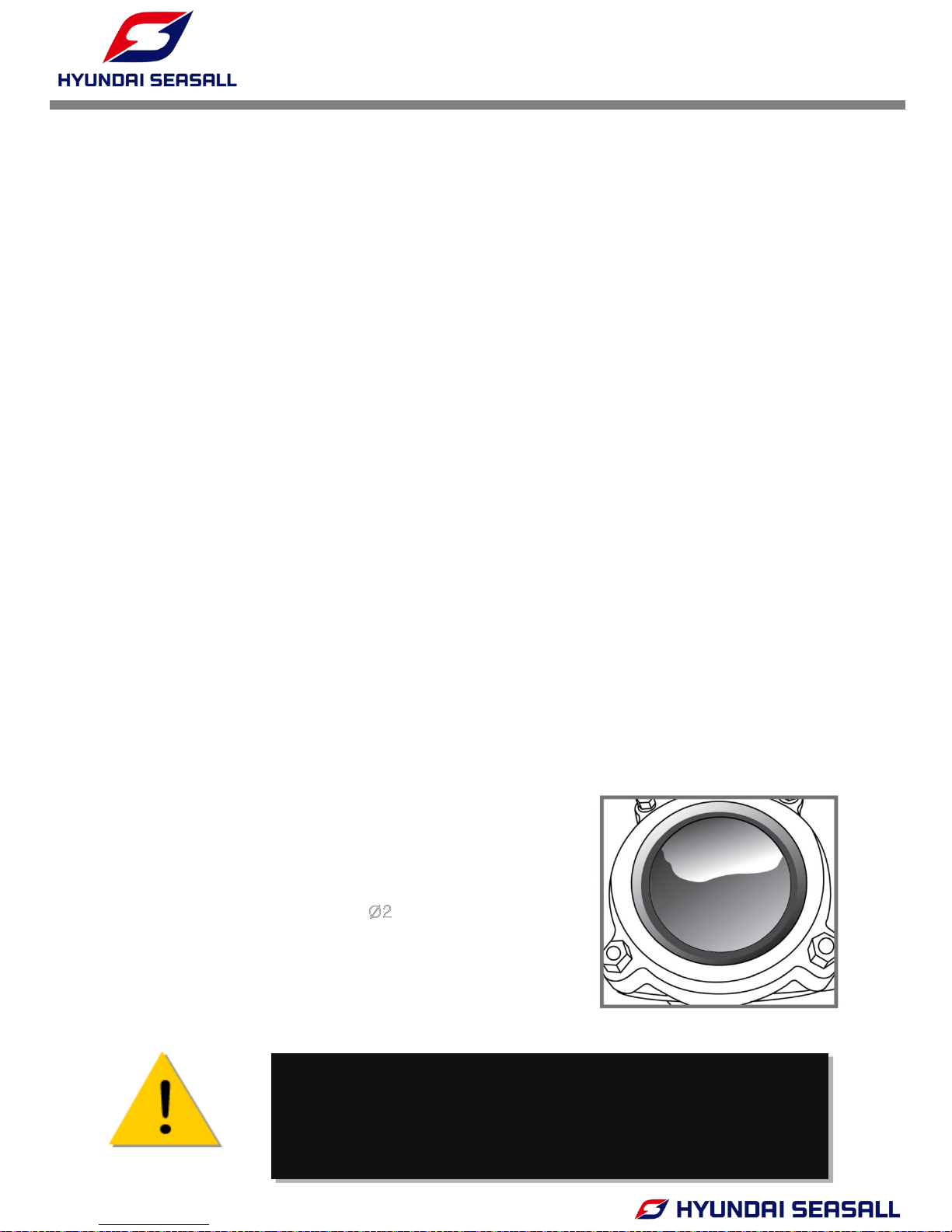
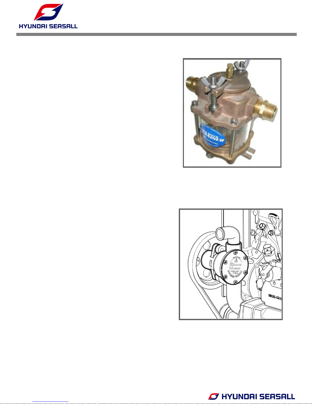
2.2 WATER STRAINER
• Strainer should be located in an area where it will
be easily accessible for periodic seawater flow
inspection and cleaning.
• The size of strainer must be of sufficient capacity
to pass the seawater (a flow rate over 150 liters
per minute flow rate).
• Strainer filter size should be Ø
2
• Strainer must be installed after water inlet valve in
order to allow user to shut off seawater when
cleaning strainer filter.
CAUTION
IF THE SEAWATER STRAINER IS NOT PROPERLY ASSEMBLED, AIR
CAN BE SUCKED INTO THE COOLING CIRCUIT, DISTURBING THE
VACUUM PROCESS. THIS CAN CAUSE THE ENGINE TO OVERHEAT.
INSTALLATION & OPERATION MANUAL
U125 Series Engines
-20-
2.3 SEAWATER PUMP
• Stop the engine and close the water valve.
• Remove the filter cap.
• Remove the filter element, flush it thoroughly
with clean water or compressed air.
• Insert the cleaned filter element and screw on
the filter cap.
• Check the cap and the gasket for correct
seating and sealing.
• Open the water valve.
• Start the engine and check if there is water
leakage.
CLEAN STRAINER FILTER
• The internal diameter of hose connected to
seawater pump inlet should be Ø32.
• The cross section of the hose may shrink due to
inlet pressure drop. Therefore, the hose from
water pickup in the boat’s hull to the seawater
pump inlet should be as short as possible and
must be made of steel wire reinforced material.
• The seawater pump impeller must be checked
periodically and replaced if necessary.
INSTALLATION & OPERATION MANUAL
U125 Series Engines
-21-
CAUTION
DO NOT RUN THE ENGINE WITHOUT SEAWATER. THE SEAWATER
PUMP IMPELLER WILL BE DAM AGED. BEFORE STARTING THE
ENGINE, BE SURE TO SUPPLY SEAWATER TO THE PASSAGES.
CAUTION
IMPELLER DAMAGE MAY OCCUR IF APPROPRIATE TOOLS ARE NOT
USED WHEN REMOVING THE IMPELLER. MAKE SURE TO CHECK ORING CONDITION AFTER SEAWATER PUMP REASSEMBLY.
CAUTION
DO NOT INSTALL ADDITIONAL DEVICES WHICH COULD OBSTRUCT
THE FLOW OF SEAWATER. THIS CAN CAUSE THE ENGINE TO
OVERHEAT.
• Stop the engine and close the water valve.
• Remove the impeller housing cover.
• Remove the impeller from inside the seawater pump.
• Check the condition of impeller and bushing.
• Apply soapy water to impeller when assembling, and reassemble towards rotation direction.
• Replace of the O-ring on the impeller housing cover.
• Open the water valve.
• Start the engine and check if there is water leakage.
2.4 CHECKING SEA WATER PUMP & IMPELLER
CAUTION
IF ASSEMBLY IS NOT CONDUCTED PROPERLY, AIR CAN BE SUCKED
IN, DISTURBING THE VACUUM PROCESS. THIS CAN CAUSE THE
ENGINE TO OVERHEAT.
INSTALLATION & OPERATION MANUAL
U125 Series Engines
-22-
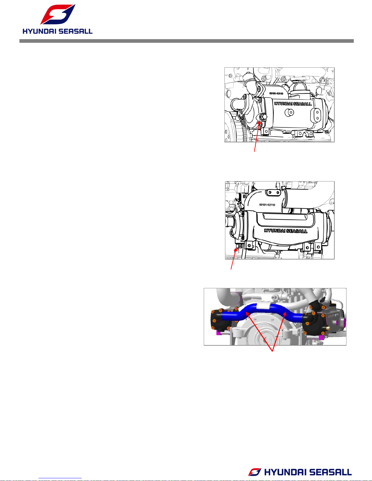
2.5 SEA WATER DRAIN
• Remove anode, then please let the sea water drain.
• Removing and Inspection procedure
1. Remove the anode plugs on the heat exchanger
(A) and the intercooler (B).
2. Squeeze the hose (C) connecting the heat
exchanger to the intercooler several time to
ensure that seawater does not remain in the
hose and bundle.
3. While anodes are removed, inspect for usability
(See Chapter 11 – Anti-Corrosion System).
4. Replace anode plugs before running engine.
(A) Anode plug (water)
HEAT EXCHANGER
INTERCOOLER
(B) Anode plug (water)
(C)
INSTALLATION & OPERATION MANUAL
U125 Series Engines
-23-
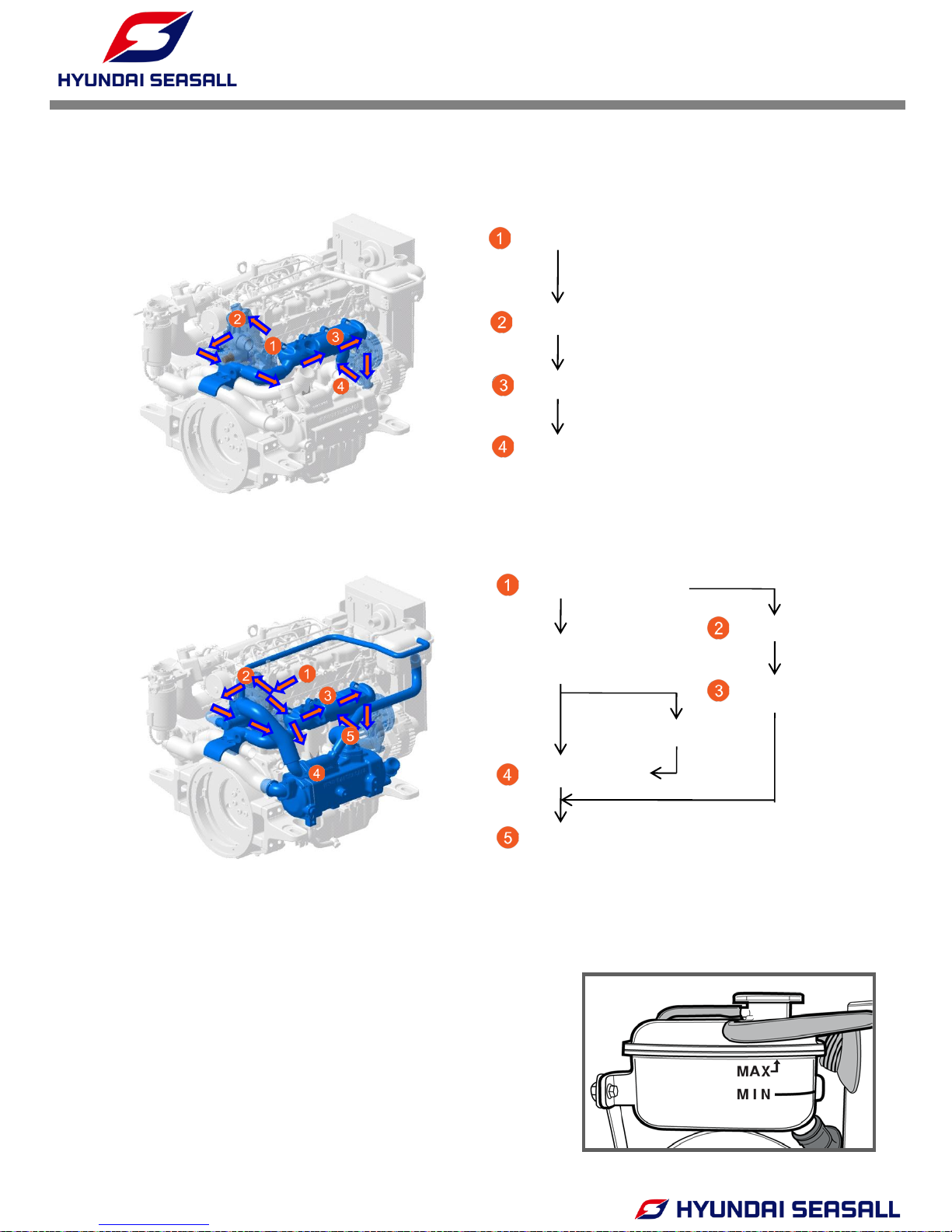
THERMOSTAT OPENED
THERMOSTAT CLOSED
• The high-pressure cooling system has a reservoir
filled with year-round antifreeze coolant. The reservoir
is filled at the factory.
• The coolant level should be between MAX and MIN
marks on the side of the coolant reservoir when the
engine is cool.
3.1 ENGINE COOLANT
① Engine coolant outlet
② Engine oil cooler
③ Exhaust manifold
④ Engine coolant inlet
① Engine coolant outlet
② Engine oil cooler
Thermostat opened
(opening temp 85℃)
③ Exhaust manifold
Expansion tank
④ Heat exchanger
⑤ Engine coolant inlet
3. ENGINE COOLANT FLOW
 Loading...