

Hyundai HY55200-3, HY75270-3 User Manual

PAGE 2
CONTENTS
1.
PARTS
3.
2. INTRODUCTION 4.
3. ELECTRICAL NOTES 5.
4. INSTALLATION 5/6.
5. START UP 6/7.
6. MAINTENANCE 7/8/9.
7. PRESSURE SWITCH ADJUSTMENTS 9/10.
8. ELECTRICAL CONNECTIONS 10/11.
9. SPECIFICATIONS 12.
10. DECLARATIONS of CONFORMITY 12.
11. RECYCLING 13.
PAGE 3
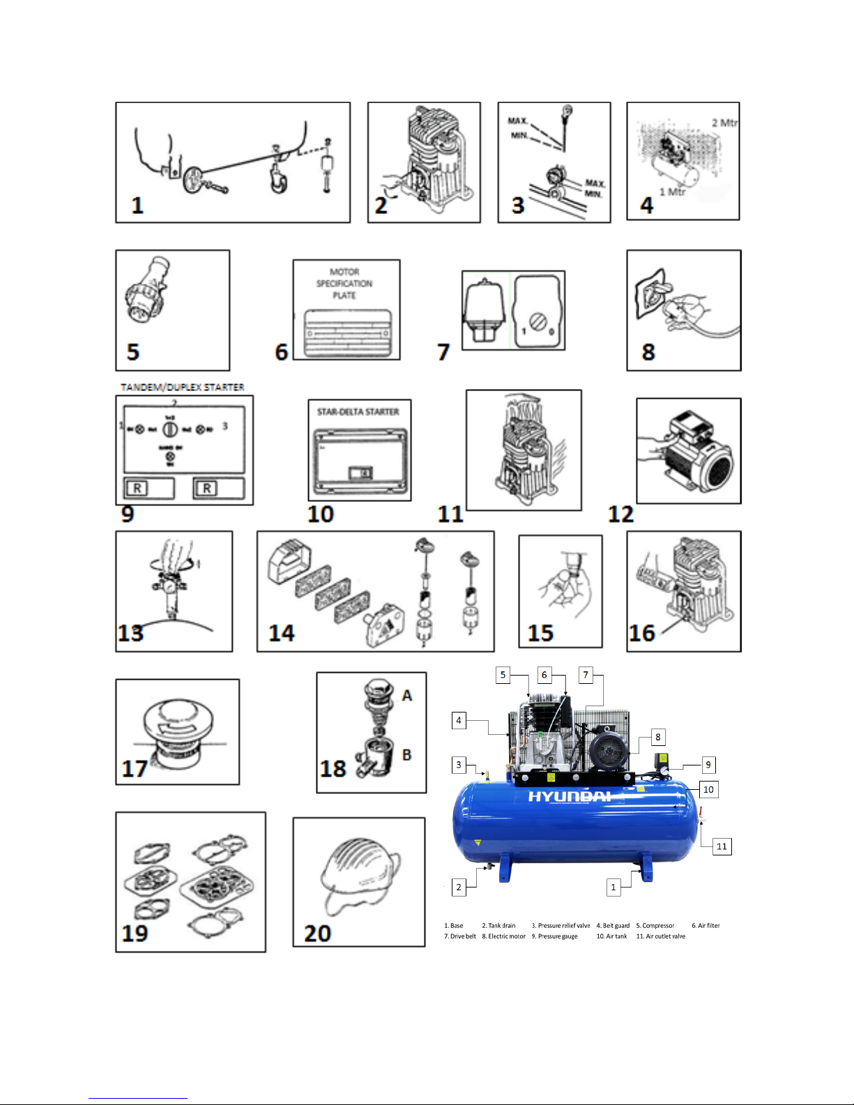
1. PARTS.

PAGE 5
2. INTRODUCTION.
Read this manual carefully before installing, using or carrying out any maintenance on your
compressor.
This instruction manual has been written to simplify installation, maintenance and general use
of your new compressor. Strict observance to the content of this manual is essential to ensure
a correct and economical operation of the compressor.
The “Warning” notes, underline those operations which, if not carried out correctly could
cause damage to the equipment and injury to the user.
We strongly recommend only genuine Hyundai replacement spare parts are used, which will
guarantee the efficiency and service life of the compressor.
N.B. Warning
Use of non-genuine parts invalidates our warranty on your compressor.
INSTALLATION.
Having removed the compressor from it’s packaging and check that it is in perfect condition; you are now
ready to install your new compressor as follows:
2.1 Portable compressors.
Fit the wheels and rubber foot as required (Fig 1).
Continue as stationary.
2.2 2 Stationary compressors.
2.2a Site the compressor on a level surface in a clean dry area (Fig 4). It is essential the
compressor should has a 1 metre clearance from the surrounding walls and 2 metres from the
ceiling to ensure proper ventilation and efficient cooling. If the compressor is sited in a small
room there must be a minimum of two air changes per min to provide adequate ventilation.
To achieve this it may require the use of both an input and extract fans to ensure the room
temperature does not exceed 40°C.
2.2b It is further recommended that compressors used for painting be located in a separate
room, away from the area where sanding/grinding and painting is done. Abrasive particles or
paint found to have clogged the air intake filter and valves shall automatically void warranty.
N.B. Minimum Working temperature +5°C
2.2c Compressors that are receiver mounted or skid-base packages should not be bolted to
the floor but installed on anti-vibration mounts. When using anti-vibration mounts it is
essential to use a flexible pipe to connect the compressor to the installed system.
2.2d Air leaks if not corrected will cause excess wear in the compressor and can result in the
compressor not being able to provide the air required.

PAGE 6
3. ELECTRICAL NOTES.
3.3 Always use a qualified electrician to connect the compressor to the mains.
Check electrical supplies match compressor specification as per the motor
information plate (fig 6).
3.4 All compressors are supplied with a power cable of 2 metres for connection to a
fused isolator close to the compressor. (not supplied) sited close to the compressor.
3.5 Single phase compressors can be fitted with an appropriate plug (Fig 5) & (Table
1). It is extremely important that attention is ,paid to the technical data sheet to
establish the correct fuse and plug are used for the particular compressor in
question.
N.B. Warning
Failure to use the correct plug and fuse could cause damage to the equipment and injury to the
user, and will invalidate the warranty.
Three phase 2hp to 7.5hp compressors are fitted with a direct on line starter/pressure switch
complete with 2 metres of cable for connection to a fused isolator (not supplied).
A 10hp three phase compressor is supplied with a star-delta starter, which is pre-wired with 2
metres of cable. The starter should be connected to a fused isolator (not supplied).
TABLE 1
HP
Supply voltage
Fuse / Plug type
2-3*
230/1/50
13 amp flat 3 pin - EEC282
3-4
230/1/50
32 amp 3 pin - EEC282
2-3-3.5-4
400/3/50
16 amp 4 pin - EEC282
5.5-7.5-10
400/3/50
32 amp 4 pin -
* Only compressors fitted with soft start and low current motors can be used with 13 amp plugs.
TANDEM/DUPLEX COMPRESSORS
• Installation for these compressors requires a qualified electrician to connect the compressor
to the mains.
• Both tandem and duplex compressors (two pumps on same receiver) are supplied with a
timed starter to make sure that there is a time lapse between each compressor starting.
4. INSTALLATION.
Secure starter panel (when supplied) to the wall or a fixed support and connect to a fused
isolator adjacent to the control panel, or connect power cable direct to fused isolator (not
supplied). Cable to the isolator should be suitable for the total HP/Kw been used (see Table 2).
If an extension to the supply is required, it should have a cross section for the wires in
proportion to its length, (see Table 2).
VALID SECTION FOR A MAXIMUM LENGTH OF 20 METRES
TABLE 2
HP/kw
220/230 Volt
380/400 Volt
2-3-3.5/1.5-2.2-2.6
2.5 sq mm
1.5 sq mm
5.5/4
2.5 sq mm
2.5 sq mm
10/7.5
4.0 sq mm
20/15
10 sq mm
N.B. Warning any extension of supply cable should not be less in section than the cable fitted to
the compressor by the factory.
 Loading...