

Hyundai HX300, HX300L, HX200L-2000, HX400, HX200L User Manual

Hyundai Robot
HX300060301MME2
Manipulator Maintenance Manual
- HX200L , HX200L-2000,
- HX300 , HX300L,
- HX400

Any copy or even partial is not allowed without prior written authorization from
It may not be provided to the third party, nor used for any other purposes.
The information presented in the manual is the property of HHI.
HHI.
HHI reserves the right to modify without prior notification.
Printed in Korea - Oct. 2005. 1st Edition
Copyright ⓒ 2005 by Hyundai Heavy Industries Co., Ltd.

Contents
1. Safety
1. Safety............................................................................................ 1-1
1.1. Introduction............................................................................................1-2
1.2. Relevant Safety Regulations ................................................................. 1-4
1.3. Safety Training.......................................................................................1-4
1.4. Safety Related Nameplate..................................................................... 1-5
1.4.1. Safety Marking....................................................................................1-5
1.4.2. Safety Nameplate ............................................................................... 1-6
1.5. Definition of Safety Functions ................................................................1-7
1.6. Installation .............................................................................................1-8
1.6.1. Safety Fence.......................................................................................1-8
1.6.2. Placement of Robot & Peripheral Equipment.................................... 1-10
1.6.3. Installing the Robot ...........................................................................1-12
1.6.4. Space for Robot Installation .............................................................. 1-14
1.7. Safety Operation for Robot Handling ...................................................1-15
1.7.1. Safety Precautions for Robot Handling.............................................1-15
1.7.2. Safety Precautions for Operating Test..............................................1-18
1.7.3. Safety Precautions for Automatic Operation.....................................1-19
1.8. Safety Precautions for Access to Safety Fence...................................1-20
1.9. Safety Precautions for Maintenance and Repair.................................. 1-21
1.9.1. Safety Precautions for Hi4a Controller Maintenance and Repair...... 1-21
1.9.2. Safety Precautions for Robot System & Manipulator Maintenanace. 1-22
1.9.3. Necessary Actions after Maintenance and Repair ............................1-23
1.10. Safety Functions ................................................................................1-24
1.10.1. Operating a Safety Circuit...............................................................1-24
1.10.2. Emergency stop..............................................................................1-26
1.10.3. Operating Speed.............................................................................1-29
1.10.4. Connecting the Safety Devices.......................................................1-29
1.10.5. Restricting the working Envelope.................................................... 1-30
1.10.6. Monitoring Function ........................................................................ 1-30
1.11. Safety Related to End Effectors.........................................................1-31
1.11.1. Gripper ............................................................................................ 1-31
1.11.2. Tool / Workpiece.............................................................................. 1-32
1.11.3. Pneumatic and Hydraulic Systems ................................................. 1-32
1.12. Liabilities............................................................................................1-33
2. Specifications
2. Specifications .............................................................................. 2-1
2.1. Robot Machinery Part ............................................................................2-2
2.2. Location of Robot Identification Plate .................................................... 2-3
2.3. Basic Specifications............................................................................... 2-4
2.4. Robot Dimension and Working Envelope .............................................. 2-6
i

Contents
2.5. Axis Identification.................................................................................2-11
2.6. Details of Wrist Axis Attachment Surface ............................................ 2-12
2.7. Details of Upper 1st ARM Attachment Surface..................................... 2-13
2.8. Application Wiring and Inspection Wiring Diagram .............................. 2-14
2.8.1. Details of Customer Application Connectors..................................... 2-15
2.9. Restricting the Working Envelope........................................................ 2-16
2.9.1. Axis 1(Axis S).................................................................................... 2-16
3. Instructions
3. Instructions.................................................................................. 3-1
3.1. Robot Component Name .......................................................................3-2
3.2. Location of Safety Nameplate................................................................ 3-3
3.3. How to operate ......................................................................................3-4
3.3.1. Using Crane........................................................................................3-4
3.3.2. Using Forklift Truck ............................................................................. 3-6
3.4. How to Install ......................................................................................... 3-7
3.4.1. Operating Conditions ..........................................................................3-7
3.4.2. Installating the Robot Manipulator ...................................................... 3-8
3.4.3. Dimension of Installation Surface ....................................................... 3-9
3.4.4. Accuracy of Installation Surface........................................................ 3-10
3.5. Allowable Load of Wrist Axis................................................................ 3-11
3.6. Recommended Standy Posture...........................................................3-16
4. Inspection
4. Inspection .................................................................................... 4-1
4.1. Inspection Item and Period ....................................................................4-2
4.2. Inspection Item and Period ....................................................................4-3
4.3. Inspection of Main External Bolts........................................................... 4-5
4.4. Inspection of Wrist Backlash.................................................................. 4-7
4.5. Inspection Internal Wiring ...................................................................... 4-8
4.5.1. The Conditions of Safety Inspection ................................................... 4-8
4.5.2. Inspection Part....................................................................................4-9
5. Maintenance
5. Maintenance................................................................................. 5-1
5.1. Grease Replenishment/Replacement ....................................................5-2
5.1.1. S-Axis Reduction Gear ....................................................................... 5-3
5.1.2. H-Axis Reduction Gear .......................................................................5-4
5.1.3. V-Axis Reduction Gear ....................................................................... 5-6
5.1.4. R2-Axis Reduction Gear .....................................................................5-8
5.1.5. B-Axis Reduction Gear ....................................................................... 5-9
5.1.6. R1-Axis Reduction Gear ................................................................... 5-11
5.1.7. Bearing Joint Parts ...........................................................................5-13
ii

5.1.8. A1 Frame - Gear Box........................................................................5-14
5.1.9. Wrist - Gear Box ............................................................................... 5-15
5.2. Battery Replacement ........................................................................... 5-16
5.2.1. Instructions for Battery Storage......................................................... 5-18
5.3. Internal Wiring......................................................................................5-19
5.3.1. Wiring Connection Diagram..............................................................5-20
6. Troubleshooting
6. Trobleshooting............................................................................. 6-1
6.1. Troubleshooting Procedure ................................................................... 6-2
6.2. Trouble Symptoms and Possible Causes ..............................................6-3
6.3. Diagnostics and Resolutions for Major Parts Failure .............................6-4
6.3.1. Fulcrum Bearings................................................................................6-4
6.3.2. Reduction Gear...................................................................................6-5
6.3.3. Brakes ................................................................................................6-7
6.3.4. Motor ..................................................................................................6-8
6.3.5. Encoder .............................................................................................. 6-9
6.4. Motor Replacement ............................................................................. 6-10
6.4.1. Necessary Tools and Parts ............................................................... 6-12
6.4.2. How to Replace Motor ...................................................................... 6-13
6.5. Encoder Zero Setting...........................................................................6-15
6.5.1. Zero Setting ...................................................................................... 6-16
6.5.2. Encoder Reset ..................................................................................6-17
6.5.3. Confirming the Reset ........................................................................6-19
6.5.4. Encoder Calibration(Data input) and Selection.................................6-20
7. Recommended Spare Parts
7. Recommended Spare Parts ........................................................ 7-1
8. Internal Wiring Diagram
8. Internal Wiring Diagram .............................................................. 8-1
8.1. Manipulator Configuration...................................................................... 8-2
8.2. Wiring Diagram ......................................................................................8-3
9. Decommissioning
9. Decommissioning........................................................................ 9-1
iii

Contents
List of Figures
List of Figures
Fig 1.1 Recommended Size for Fence and Gate Hole (Square Gate)......... 1-8
Fig 1.2 Recommended Size for Fence and Gate Hole (Slot Gate) .............. 1-8
Fig 1.3 Placement of Peripheral Equipment and Operator ........................ 1-10
Fig 1.4 Space for robot installation............................................................. 1-14
Fig 1.5 Robot’s Safety Circuit .................................................................... 1-24
Fig 1.6 Emergency Stop ............................................................................ 1-27
Fig 1.7 Emergency Stop Connection of External System .......................... 1-28
FIg 2.1 Robot Machinery Part...................................................................... 2-2
Fig 2.2 The location of identification plate.................................................... 2-3
Fig 2.3 Robot Dimension and Working Envelope : [HX300] ........................ 2-6
Fig 2.4 Robot Dimension and Working Envelope : [HX400] ........................ 2-7
Fig 2.5 Robot Dimension and Working Envelope : [HX200L]....................... 2-8
Fig 2.6 Robot Dimension and Working Envelope : [HX200L-2000] ............. 2-9
Fig 2.7 Robot Dimension and Working Envelope : [HX300L]..................... 2-10
Fig 2.8 Robot Dimension and Axis [HX300/400/200L/200L-2000/300L] .....2-11
Fig 2.9 Details of Wrist Axis Attachment Surface : [HX300/400/300L] ....... 2-12
Fig 2.10 Details of Wrist Axis Attachment Surface : [HX200L] ................... 2-12
FIg 2.11 Details of Upper 1st ARM Attachment Surface............................. 2-13
Fig 2.12 Application Wiring and Inspection Wiring Diagram ...................... 2-14
Fig 2.13 Details of Application Connector (Encoder) ................................. 2-15
Fig 2.14 Details of Application Connector (Power)..................................... 2-15
Fig 3.1 Identification of Robot Components................................................. 3-2
Fig 3.2 Location of Safety Nameplate.......................................................... 3-3
Fig 3.3 How to Transport: Using crane [HX300/400].................................... 3-4
Fig 3.4 How to Transport: Using crane [HX200L/300L]................................ 3-5
Fig 3.5 How to Transport : Using Forklift Truck
[HX300/400/200L/200L-2000/300L] .............................................. 3-6
Fig 3.6 Dimension of Robot Installation..................................................... 3-9
Fig 3.7 Accuracy of Installation surface ..................................................... 3-10
Fig 3.8 Wrist Axis Torque Mapping:[HX300/300L]...................................... 3-14
Fig 3.9 Wrist Axis Torque Mapping : [HX400]............................................. 3-14
Fig 3.10 Wrist Axis Torque Mapping : [HX200L]......................................... 3-15
Fig 3.11 Recommended Standby Posture ................................................. 3-16
Fig 4.1 Inspection Part for Main Bolts [HX300/400/300L] ............................ 4-6
Fig 4.2 Abnormal Backlash Inspecting Directions ........................................ 4-7
Fig 4.3 Cable Inspection Parts : [HX300/400/200L/200L-2000/300L].......... 4-9
Fig 5.1 Explains of internal wiring .............................................................. 5-20
Fig 5.2 Wiring connection diagram : [HX300/400/200L/200L-2000/300L].. 5-21
Fig 6.1 How to prevent dropping of ARM Axis H & V ..................................6-11
iv

Fig 6.2 Encoder Reset Connector.............................................................. 6-18
Fig 8.1 Manipulator Configuration................................................................ 8-2
Fig 8.2 Motor and Brake wiring connection No.1 ......................................... 8-3
Fig 8.3 Motor and Brake wiring connection No.2 ......................................... 8-4
Fig 8.4 Encoder wiring Connection No.1 ..................................................... 8-5
Fig 8.5 Encoder Wiring Connection No.2..................................................... 8-6
Fig 8.6 Encoder Wiring Connection No.3..................................................... 8-7
Fig 8.7 Application Wiring Connection No.1................................................. 8-8
Fig 8.8 Application Wiring Connection No.2................................................. 8-9
List of Tables
List of Tables
Table 1-1 Safety marking............................................................................. 1-5
Table 1-2 State of robot stop...................................................................... 1-17
Table 2-1 Basic Specifications for Models.................................................... 2-4
Table 2-2 Axis Motion..................................................................................2-11
Table 3-1 Components name....................................................................... 3-2
Table 3-2 Allowable load weight..................................................................3-11
Table 3-3 Allowable Load Torque................................................................3-11
Table 3-4 Allowable Moment of Inertia ....................................................... 3-12
Table 4-1 Inspection Schedule..................................................................... 4-2
Table 4-2 Inspection Items and Periods....................................................... 4-3
Table 4-3 Inspection part for main bolts....................................................... 4-5
Table 6-1 Trouble phenomenon and cause.................................................. 6-3
Table 6-2 Motor Weight.............................................................................. 6-10
Table 6-3 Necessary Tools......................................................................... 6-12
Table 6-4 Necessary parts......................................................................... 6-12
Table 6-5 Reset connectors corresponding to axes................................... 6-17
Table 6-6 Data range after resetting .......................................................... 6-20
Table 7-1 Spare Parts ListⅠ ........................................................................ 7-2
Table 7-2 Spare Parts ListⅡ ........................................................................ 7-4
Table 7-3 Spare Parts List Ⅲ ...................................................................... 7-5
Table 7-4 Spare Parts List Ⅳ ...................................................................... 7-6
Table 7-5 Spare Parts List Ⅴ ...................................................................... 7-7
Table 9-1 Materials of each part................................................................... 9-2
v


1. Safety
1. Safety
1
Safety
1-1

1.
Safety
HX200/HX200L-2000/HX300/HX300L/HX400
1.1. Introduction
The main purpose of this chapter is to describe the safety precautions for users and
operators who repair and manipulate the industrial robot.
This manual describes safety precautions for robot manipulator and controller, in
comply with the requirement of ANSI/RIA R15.06-1999, Standard for Safety,
Industrial Robots, and qualified with safety regulations. The technical description and
installation method of robot system is presented in detail at the specifications
regarding installation of robot manipulator and controller.
Every operator, who installs, replaces, adjusts, manipulates, maintains, and repairs,
must read thoroughly and fully understand the manipulation and maintenance
manual, in particular, the special attention must be paid to the WARNING symbol, the
most important marking related to the safety.
Installation, replacement, adjustment, manipulation, maintenance, and repair of robot
system must be performed by the personnel who was duly trained for these purposes,
following the indicated operating procedure.
This company is planning and carrying out the relevant training such as maintenance,
repair, and manipulation for the above operations, so robot users make sure that
robot operators should get the relevant training. And make sure that the robot
handling work should be carried out only by the operators who completed this
training course.
The Users of HR and HX industrial robots have a responsibility under the safety
relavant regulations valid in the country where the robot is installed, and a
responsibility to properly design, install, and operate the safety devices to protect
workers.
The dangerous zone of robot system, that is the working range in which the robot,
tool, and peripheral equipment are operated, must be safeguarded to prevent
workers or objects from entering the zone. If a person or object should nevertheless
enters the dangerous zone, make sure that the robot system is immediately shut
down by emergency stop system. The operators of robot system have a
responsibility to take all necessary steps to make correct installation, examination
and operation of the relevant safety devices.
This manual is provided for the utilization of HR and HX Series Manipulator models
and Hi4a controller.
Valid application and invalid environment of HR and HX Series robots are as follows.
Application
1-2

1. Safety
It is applied to the 6-axis industrial robot used by installing on the surface of wall or
plane (axes addable). It is also appropriate for controlling operation in the dotted
section or consecutive section.
Major application is
Spot welding
Handling
Assembly
Application such as Sealing
MIG/MAG welding
Palletizing
Grinding
For the other use than the above emergency application, make a contact with our
company to consult on the robot use and possible applications.
Invalid environment
Our robot must not be used in a highly explosive environment and the areas
contaminated by oil, flammable materials or chemical materials. (Prohibited to be
installed and manipulated.)
1-3

HX200/HX200L-2000/HX300/HX300L/HX400
1.2. Relevant Safety Regulations
The robot is designed as per ISO10218.Jan. 1992 , safety standards for industrial
robots, and furthermore in comply with ANSI/RIA 15.06-1999 regulations.
1.3. Safety Training
All the personnel who intend to teach, operate or inspect the robot must be trained in
an approved robotic operation and safety training course before start-up. The safety
training course includes the following details:
Purpose and functions of safety devices
Safety procedure to handle the robot
Performance of robot or the robot system and possible hazards
Tasks associated with any specific robot applications
Safety concepts, etc.
1-4
1. Safety
1.4. Safety Related Nameplate
1.4.1. Safety Marking
For the purpose of effective safety instructions, the following safety symbols are used
in this manual.
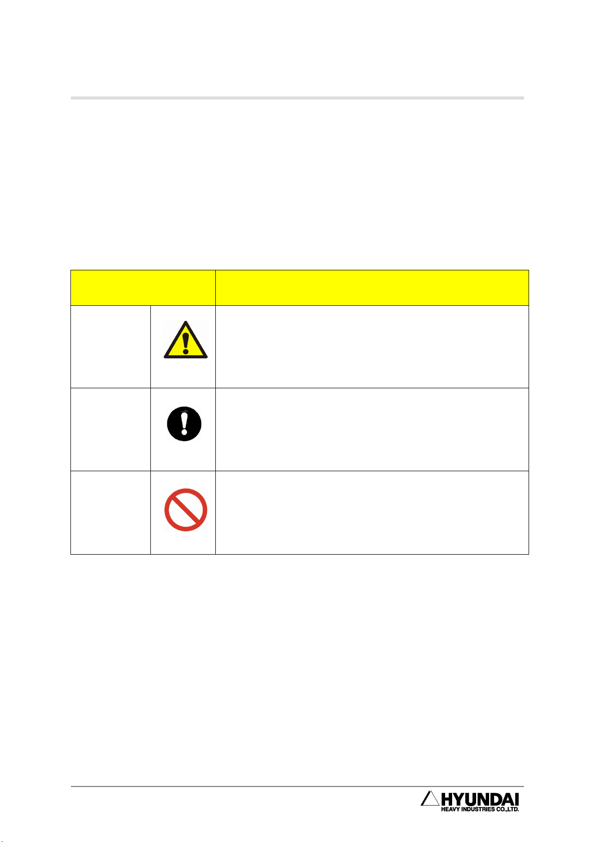
Table 1-1 Safety marking
Symbols Descrptions
Warning
Mandatory
Prohibited
Indicate a potentially hazardous situation which, if not
avoided, could result in death or serious injury to
personnel and damage to equipment. The special
attention must be paid to the operation and handling.
Indicate the compulsory measures that should be
performed.
Indicate the prohibited actions and/or operations that
should not be performed.
1-5

HX200/HX200L-2000/HX300/HX300L/HX400
1.4.2. Safety Nameplate
Identification plates, warning label and safety symbols are attached to the robot and
to the inside and outside of control panel. The designation labels and cable Mark for
wire harness between the robot and control panel, and the cables inside/outside of
control panel are provided.
All of these plates, labels, symbols and marks constitute safety-relevant parts of the
robot and the control panel. They must remain attached to the robot manipulator and
control panel at their clearly visible positions all the time for the safety and their full
performance.
The painted markings on the floor and signs indicating dangerous zones must be
clearly distinguished in form, color, and style from other markings on the machine
near the robot system or inside the plant facilities where the robot system is installed.
It is forbidden to remove, cover, or paint over by way of spoiling the
clearly visible identification plates, warning labels, safety symbols,
designation labels and cable marks.
1-6

1. Safety
1.5. Definition of Safety Functions
Emergency Stop Function - IEC 204-1,10,7
There is one emergency stop button on the controller and teaching pendant
respectively. If necessary, additional emergency buttons should be able to connected
to the robot's safety chain circuit. The emergency stop function, which overrides all
other robot controls, stops all moving parts by disconnecting power supply, and
removes drive power to prevent the use of other dangerous functions controlled by
the robot.
Safety Stop Function - ISO 10218(EN 775),6.4.3
When a safety stop circuit is provided, each robot must be delivered with the
necessary connections for the safeguards and interlocks associated with this circuit.
The robot should have a number of electrical input signals which can be used to
connect external safety devices, such as safety gates, safety pads, and safety lamps.
These signals allow the robot's safety functions to be activated by all equipment,
including peripheral equipment and the robot itself.
Speed Limiation Function - ISO 10218(EN 775),3.2.17
In a manual mode, the speed of robot is strictly limited to 250 mm per second as
maximum.
The speed limitation applies not only to the TCT(Tool Coordinate Time), but to all
parts of manual mode robot. The speed of equipment mounted on the robot should
be possibly monitored.
Restricting working Envelope - ANSI/RIA R15.06-1999
The working envelope of robot axes should be restricted using software limits.
Axis 1,2, and 3 can also be restricted by means of mechanical stopper.
Operation Mode Selection - ANSI/RIA R15.06-1999
The robot must be operated either manually or automatically. In a manual mode, the
robot must be operated only by using the teach pendant..
1-7
HX200/HX200L-2000/HX300/HX300L/HX400
1.6. Installation
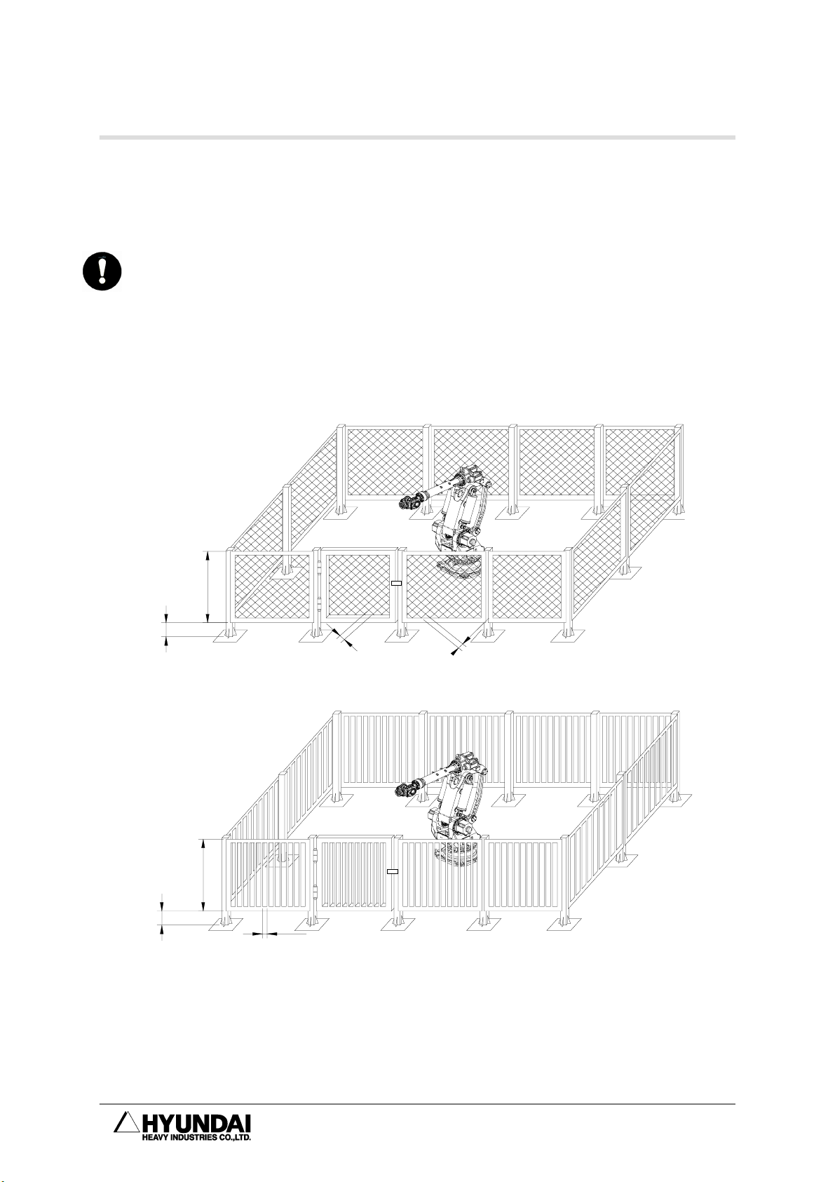
1.6.1. Safety Fence
Install safety fence against the possible collision between the robot and workers, so
that no worker may approach the robot .When operators or other personnel enter the
robot's working envelope by accident, it may cause an accident. Install the safety
fence to stop the robot when one, who intends to replace for TIP DRESSING or TIP
replacement, or to inspect welding equipment, opens the fence gate and approaches
the equipment during operation.
1.5m (60") M in
0.3m (12") M a x
4.9cm(1 .87 5 ") Max
4.9cm(1 .87 5 ") Max
Fig 1.1 Recommended Size for Fence and Gate Hole (Square Gate)
1.5m (60") M in
0.3m (12") M ax
4.9cm (1.87 5") M ax
Fig 1.2 Recommended Size for Fence and Gate Hole (Slot Gate)
① Install the safety fence to cover the robot’s working envelope and to secure
enough space for teaching and maintenance working. The safety fence
should also be firmly installed so that it is hardly accessible and removable.
1-8

1. Safety
② The safety fence should be a fixed type in principle, using harmless materials
that do not have any broken surface or projecting part.
③ Install the safety fence with an entrance gate, and register the safety plug at
the gate so that it does not open unless pulling the plug out. Interlock the
robot to be MOTORS OFF when the safety plug is pulled out., or wire the
robot to be MOTORS OFF when the safety fence is open. (Refer to “11.
Connecting the Other Signals”, Hi4a Controller Manual)
④ When intending to operate the robot with the safety plug pulled out, wire the
robot as a low-speed play mode. (Refer to “11. Connecting the Other Signals”,
Hi4a Controller Manual)
⑤ For immediate emergency stop, install emergency stop button wihin
operator’s easily accessible distance.
⑥ If the safety fence is not installed, install other devices substituting for the
safety plug in the whole place within the robot’s working envelope, such as
photoelectric switch and mat switch. These devices may stop the robot
automatically when a person enters the working envelope.
⑦ The robot’s working envelope(dangerous zone) should be distinguished from
other zones by painting its floor.
1-9
HX200/HX200L-2000/HX300/HX300L/HX400
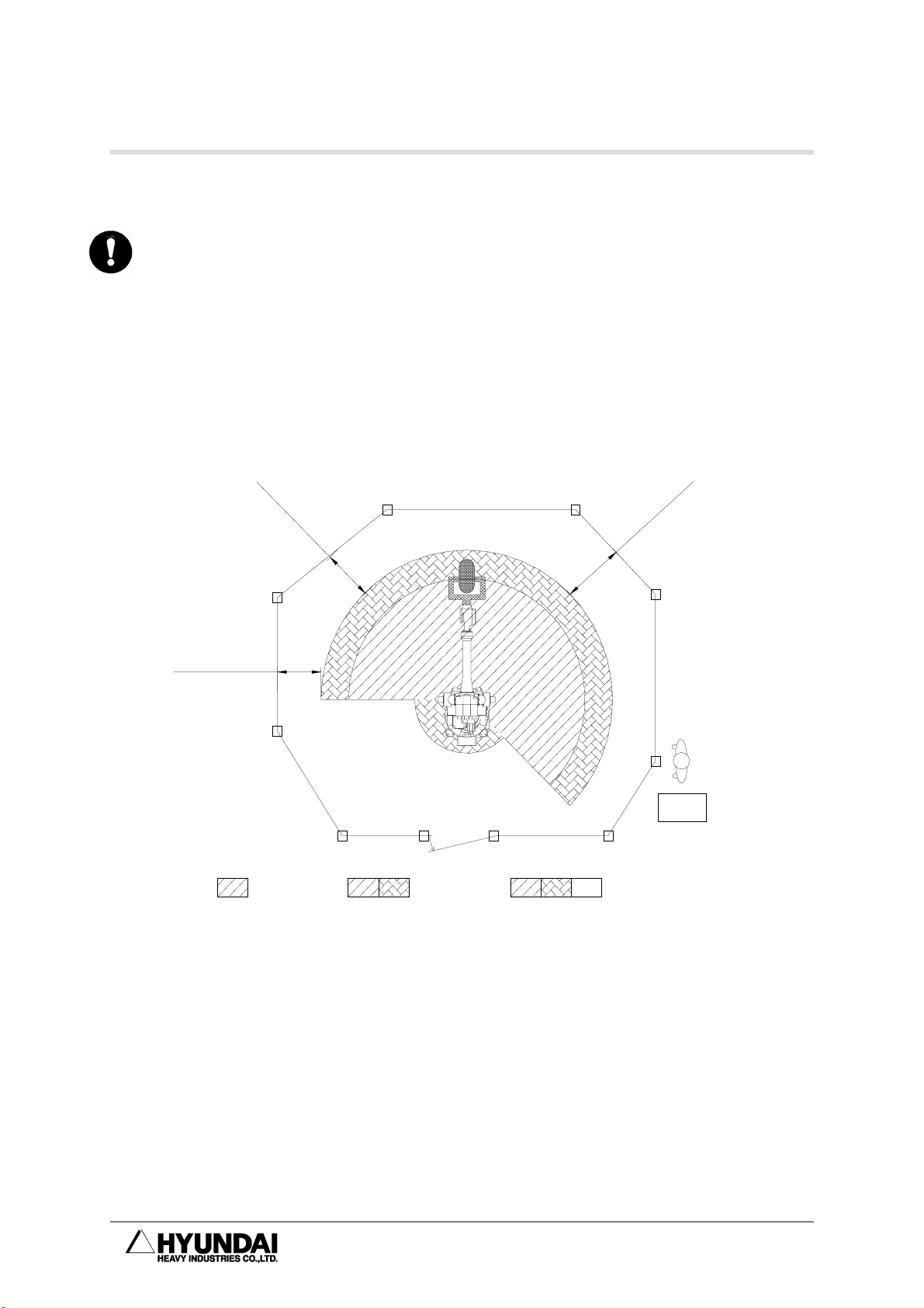
1.6.2. Placement of Robot & Peripheral Equipment
(1) Make sure that the power supply is off before operating, when connecting the
primary power of controller or peripheral equipment. There is a possible
danger of electric shock because the high voltage such as 220V and 440V is
used as its primary power.
(2) Post a sign [No enter during operation] up the safety fence gate, and inform
the operators of its purport.
110 cm(44") Min
110 cm(44
Restricted
space
"
)
M
in
Interlocked Barrier Guard
Maximum
space
0
1
1
Safeguarded
space
4
4
(
m
c
Controller
M
)
"
n
i
Operator
Fig 1.3 Placement of Peripheral Equipment and Operator
(3) Arrange such devices as controller, interlock panel, and other manipulation
panels to be handled outside of the safety fence.
(4) When installing operation stand, install the emergency stop button on the
stand. Make sure that the stand stops in an emergency wherever the robot is
handled.
1-10

1. Safety
(5) Make sure that the robot manipulator and the wiring and piping of controller,
interlock panel, and timer should not be placed in the way of operator's
working range so that they would not be directly stepped on by FORK and
LIFT. There is a possible danger of accident if the workers are affected by
electricity or the wiring is down.
(6) Place the controller, interlock panel, and handling stand within the sight of
robotic performance. It may cause a serious accident to operate the robot
while the operator is working, or the robot is malfunctioning in an invisible
sight.
(7) Restrict the robot's working envelope by using soft limits and mechanical
stopper if the necessary working envelope is narrower than the holding
workable envelope. It is possible to stop the robot in advance when it moves
beyond its normal working envelope due to an abnormal condition. (Refer to
the 『Robot Manipulator Maintenance Manual』.)
(8) Welding spatters directly on the operator or around him may cause burning or
fire. Install such devices as a glare shield or a cover in the full sight of
robot's working envelope.
(9) Make sure that the device indicating the robot's running condition whether
automatic or manual mode must be noticeable even in the far distance. In the
case of automatic start-up, warning with a buzzer or warning lamp is also
valid.
(10) Make sure that there is no projecting part in the robot's peripheral equipment.
Cover it, if necessary. It usually may cause an accident if the operator comes
in touch with it. And it may lead a serious accident if the operator is
astonished at the sudden movement of robot, and conducts it.
(11) Don't make the system designed to allow the workers to carry the Work in
and out using their hands through the safety fence. It could be a cause of
accident associated with compressing or amputating.
1-11

HX200/HX200L-2000/HX300/HX300L/HX400
1.6.3. Installing the Robot
Install the robot as per the planning and layout which has been previously reviewed
and studied for its optimized performance and functionality. In case of poor
conditions for robot installation, the serious problems can take place, including error
of relative position between robot and workpiece during operation, bad performance
quality of robot caused by vibration, shortening lifetime, and cause of serious
accidents. Thus, pay attention to the following precautions when installing the robot.
General Safety Precautions
(1) Design and install the robot system properly in compliance with laws,
regulations, and safety requirements valid in the country where the robot
system is installed.
(2) All the workers for the robot system must have the complete knowledge on
the information specified in the application and supplementary manual, and
proficiently operate and handle the industrial robot.
(3) Installation workers of robot must follow the safety instructions and apply
them to the installation when they face any safety problems.
(4) System provider must ensure that all the circuits utilizing safety functions
perfectly perform in a safe way.
(5) Install main power supply to be disconnected from outside of the robot’s
working envelope.
(6) System provider must ensure that all the circuits utilizing emergency stop
function perfectly perform in a safe way.
(7) For the immediate emergency stop, install emergency stop button within the
accessible distance for the operator.
Technical Safety Precautions
(1) Eliminate any interference with peripheral equipment considering the
dimension and working envelope.
(2) Avoid such places for installing which is directly exposed to the sun,
extremely humid, contaminated by oil or chemicals, and containing a large
amount of metal powder and explosive gas.
1-12

1. Safety
(3) Install at the ambient temperature ranged 0~45℃.
(4) Secure sufficient space for the easier disassembly and maintenance.
(5) Install safety fence with a gate, and prohibit any person from entering the
robot's working envelope.
(6) Remove any obstacles out of the robot’s working envelope.
(7) Take a special measure, considering thermodynamics of controller, if the
robot is installed near the heating elements or places exposed directly to the
sun.
(8) Take a special measure if the robot is installed in a place of abundant dust
such as metal powder in the air.
(9) Install the robot not to transmit welding electric current. (In other word,
insulate SPOT GUN with/from the robot’s wrist.)
(10) Grounding is very critical in preventing electric shock and malfunction caused
by noise, and thus install as following instructions.
① Install an exclusive grounding terminal using class 3 or higher. (For the
input voltage of 400V of higher, use special class 3 or higher.)
② Connect grounding line into the grounding bus-bar inside of the control
panel.
③ In case of direct grounding on the floor by anchoring, two-point grounding
both by robot manipulator and by controller can produce a “ground loop”
and contrariwise cause abnormal operation. In this case, connect the
grounding line to the base of robot manipulator and disconnect the
second grounding point to the controller. If the robot vibrates even after
stopping, double-check the grounding status because the possible main
causes could be an incomplete grounding or “ground loop” .
④ In the use of internal transgun(GUN), there is a possible danger of
dropping because the primary power cable is directly connected to the
spot gun. In this case, directly connect the grounding line to the base of
robot manipulator in order to prevent any electric shock and protect the
control panel, but do not connect it to the controller.
1-13
Working Envelope with Tool and
HX200/HX200L-2000/HX300/HX300L/HX400
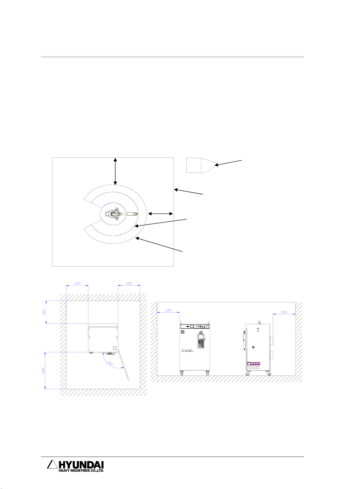
1.6.4. Space for Robot Installation
Install robot after securing sufficient space for maintaining the robot manipulator, Hi4a
controller, and other peripheral equipment. Install the robot manipulator and controller,
securing space for installation as per the guideline as described in the figure below.
Install Hi4a controller outside of the safety fence in order to monitor the robot
manipulator and to operate in a safe way.
Door
Minimum 110cm
Hi4a Controller
Minimum110 cm
SafetyFence
Working Envelope
Workpiece installed
Fig 1.4 Space for robot installation
When installing, be sure to make it easier to perform the maintenance when opening
the Hi4a Controller door. Secure the available space. The controller power in the
above Figure could change depending on the kind of controller.
1-14

1. Safety
1.7. Safety Operation for Robot Handling
Follow the safety instructions to prevent any accidents. Don't modify nor ignore safety
devices or circuits at any time, and be careful of electric shock.
All the normal operations in an automatic mode must be performed outside of the
safety fence. Check the robot's working envelope if anyone is inside before
operating.
1.7.1. Safety Precautions for Robot Handling
(1) Do not handle the robot other than such personnel as operators handling the
robot and other possible operators and supervisors who were designated as
whom duly trained in an approved robotic training course and become familiar
enough with the proper operation of the safety and robotic functions.
(2) Be sure to wear helmets, goggles, and safety shoes.
(3) Perform the work in pairs. One person must be ready to press the emergency
stop button in an emergency while the other must perform his work quickly
but carefully within the robot’s working envelope. Always check the escape
route before working.
(4) Make sure that there is no one in the working envelope when the power
source is on.
(5) Operations such as teaching must be performed outside of the robot's
working envelope. However, if the operation is performed within the working
envelope after stopping the robot, enter the envelope with safety plug or key
switch for converting to automatic mode. Make sure that other operators do
not change it into automatic mode by accident. Also, pay close attention to the
specific direction of robotic movement in case of abnormal operation and
malfunction.
(6) Supervisors should follow the instructions below.
① Be located at a place where you could take an entire view of robot, and
commit yourself to monitoring.
② Press the emergency stop button immediately when abnormality is found.
③ Anyone is forbidden to be near the operating area other than those who
are engaged in the operation.
(7) In a manual mode, the speed of teaching is limited to 250mm/sec
(8) In teaching, post a sign [Under Teaching].
1-15
HX200/HX200L-2000/HX300/HX300L/HX400
(9) Operators must pull the safety plug out, and enter the safety fence with the
plug.
(10) Do not use any devices causing noise in and around the teaching area.
(11) Handle the teaching pendant button, while checking the teaching point with
your naked eyes, and do not handle it just relying on your sense.
(12) Do not work with your back against the robot, and always pay attention to the
robot's movement.
(13) In teaching, check and examine carefully under your feet. In particular, in
high teaching for more than 2M, secure a safe zone on which you may step
before teaching.
(14) Instructions for any abnormal operations.
① Press immediately the emergency stop button when any abnormal
operations are found.
② Be sure to check if the relevant equipment is stopped when checking the
abnormality in an emergency stop.
③ In case that the robot stops automatically due to power failure, investigate
possible causes and take actions after confirming that the robot
completely stops.
④ In case of malfunction of emergency stop devices, immediately
disconnect the main power and investigate possible causes to take
necessary actions.
⑤ Investigation of the failure must be conducted only by a designated
person. For the re-operation after emergency stop, operators must
clarify the cause of failure and take necessary actions, and then operate
the robot again following the proper procedure.
(15) Write out the operating rules proper to working details and installing location
regarding the operation and handling method for the robot, and the
necessary actions for robot's any failure. In addition, it is recommended to
operate the robot in accordance with the operating rules.
(16) Instructions when the robot stops
Make sure not to approach the robot even when it seems to be stopped. Most
accidents occur from a sudden movement of robot which seemed to be
stopped when one approaches it. The conditions that the robot stops is as
follows.
1-16

Table 1-2 State of robot stop
1. Safety
No. State of Robot Drive Power Access
1
2
(Major failure, Emergency stop switch, Safety gate)
3
Input signal standby of peripheral equipment
(Minor failure, Pause switch)
(START INTERLOCK)
Pause
Emergency stop
ON X
OFF O
ON X
4 Playback Completion ON X
5 Standby ON X
Even in the accessible state of robot, be watchful against any possible
sudden movement of robot. Make sure to avoid approaching the robot
without precautions for emergency under all circumstances.
Though the access during a pause is shown in the table as『×』, allow
the access to robot with the same precautions as teaching work if the
entrance is open to take actions for minor failures(i.e. malfunction
caused by failure in arc, nozzle contact and weldment detection).
(17) Clean up any split oil, tools, and impurities in the safety fence after
completing robotic operation. Accidents such as conduction may occur in the
working envelope contaminated by oil, or scattered tools on its floor. Make a
habit of organizing and cleaning things up.
1-17

HX200/HX200L-2000/HX300/HX300L/HX400
1.7.2. Safety Precautions for Operating Test
In case of operating test, errors in design or teaching and inferiority in manufacturing
are possibly seen in the entire system such as teaching program, jig, and sequence.
Thus, be more careful and safe in case of operating test. Accidents may occur by
these combined causes.
(1) Before handling, check the stop buttons and signal functions to stop the robot
such as emergency stop button or stop button. And then, check the
abnormality - detective movements. Above all, it is the most critical to check
all the stop signals. It would be the most important to stop the robot when any
possible accidents are predicted.
(2) In case of operating test, start the robot at low speed(approximately
20%~30%) in the variable speed function, and repeat it more than one cycle
to check the movements. If any errors are found, immediately correct them.
After then, increase in speed (50% → 75% → 100%) gradually, and repeat
more than one cycle respectively to check the movements. Operating at high
speed from the very beginning may cause a serious accident.
(3) In case of operating test, it is hard to predict what problems would happen.
Do not enter the safety fence during operating test. Unexpected accidents are
likely to occur because of its low reliability.
1-18
1. Safety
1.7.3. Safety Precautions for Automatic Operation
(1) While posting a sign [Do Not Enter During Operation] up the safety fence gate,
ask the operators not to enter during operation. If the robot stops, you may
enter the safety fence under your full understanding of the situation.
(2) Be sure to check if any operators are inside of the safety fence when starting
the automatic operation. Operating without checking the presence of
operators may cause a personal injury.
(3) Before starting the automatic operation, check and confirm that the program
number, step number, mode, and starting selection are in the possible state
for automatic operation. If starting with the other programs or steps selected,
the robot could move in an unpredicted way, and lead to an accident.
(4) Before starting the automatic operation, check if the robot is properly located
to get started. Check whether the program number or step number is identical
with the location of robot. Even if it's all identical, accidents are still possible to
occur due to an abnormal movement when the robot is differently located..
(5) Be prepared to immediately press the emergency stop button when starting
the automatic operation. Immediately press the emergency stop button in
case of robot's unexpected movements or emergency.
(6) Be sure to detect any abnormalities by checking the route, condition, or
sound of robot movement. Sometimes the robot may be abnormally operated
including a sudden break down. However, it will show(give) a certain
indication before the break down. Understand the robot's normal condition
well in order to catch the symptom in advance.
(7) When any abnormality is detected from the robot, immediately stop and take
proper actions on it. Using the robot before any proper actions taken may
cause an interruption of produce as well as serious failure leading to a very
serious personal injury.
(8) When checking the robot’s movement after the proper actions taken for the
abnormality, do not operate the robot with operators inside of the safety fence.
Unexpected accidents are possibly to occur because its low reliability may
cause another abnormality.
1-19

HX200/HX200L-2000/HX300/HX300L/HX400
1.8. Safety Precautions for Access to Safety Fence
Robots are very powerful and heavy even at its low speed. When entering the safety
fence, one must observe the relevant safety regulations of its pertinent country.
The operators always must be aware of the unexpected movements of robot. Robots
are able to move fast shortly after being stopped. The operators should know that the
robot is able to move in a different route, without any notice, by means of external
signals. Thus, when trying to stop the robot during teaching or operating test, one
should be able to stop the robot with a teaching pendant or control panel.
When entering the working envelope through the safety gate, take the teaching
pendant with you so that other people may not operate the robot. Make sure to post
up the control panel a sign indicating the state of robot handling.
Read carefully and be aware of the follows when entering the working envelope.
(1) Do not enter the working envelope other than teaching person.
(2) Be sure to set the ‘handling setting’ on teaching pendant to TEACHING
LOCK.
(3) Operation set-up mode of controller must be a manual mode in the control
panel.
(4) Always wear the approved working suite.(Do not wear a loose clothes as
you please)
(5) Do not wear gloves when handling Hi4a contoller.
(6) Do not leave innerwear such as underwear, shirts, or necktie out of the
working suite.
(7) Do not wear personal accessories such as big earrings, rings, or necklaces.
(8) Make sure to wear safety shoes, helmet, and goggles and if necessary, wear
other self-protective outfit such as safety gloves.
(9) Make sure that the emergency stop circuit is working correctly and in its
proper function, turns MOTORS OFF when pressing the emergency stop
button in the control panel and teaching pendant before handling the robot.
(10) Make your posture face-to-face with the robot manipulator when performing
your work.
(11) Follow the predetermined working procedure.
(12) Be prepared for emergency exit or safe place considering that the robot may
unexpectedly rush at you.
1-20

1. Safety
1.9. Safety Precautions for Maintenance and Repair
1.9.1. Safety Precautions for Hi4a Controller Maintenance and
Repair
(1) Maintenance and repair of the robot must be performed by the personnel who
was duly trained in the special maintenance training course and has a good
knowledge of maintenance.
(2) Perform your work following the maintenance procedures for controller.
(3) Perform your maintenance and repair in a safe way by securing emergency
exit or safe place.
(4) Before the daily maintenance, repair, or changing parts, be sure to power
down. In addition, post a warning sign [Do Not Input Power] up the primary
power so that other operators may not input power by accident..
(5) When changing parts, be sure to use the specified ones.
(6) Be sure to power down when opening the Hi4a controller door.
(7) Before performing, wait for three minutes after power down.
(8) Do not touch the heat sink and regeneration resistor of servo amp because
they generate an intense heat.
(9) After completing maintenance, Be sure to close the door completely after
checking if tools or other things are still remained in the Hi4a controller.
1-21

HX200/HX200L-2000/HX300/HX300L/HX400
1.9.2. Safety Precautions for Robot System & Manipulator
Maintenanace
(1) Refer to the safety precautions for Hi4a controller maintenance and repair.
(2) Perform your maintenance and repair for the robot system and manipulator,
following the indicated procedures.
(3) Be sure to disconnect the primary power of controller. Post the warning sign
[Do not input power] up the primary power to prevent other workers from
connecting the power.
(4) Make sure that the Arm is fixed and immovable before maintenance and
repair since dropping or moving of the robot's Arm may cause a danger
during maintenance and repair. (Refer to the 『Robot manipulator
maintenance manual』.)
1-22
 Loading...