

Page 1

H-CSX10A
ACTIVE BOX SUBWOOFER АКТИВНЫЙ КОРПУСНОЙ САБВУФЕР
Instruction manual Руководство по эксплуатации
Page 2

Features
• Molded rock case
• Woofer press paper 10”
• P.W.M Mosfet power supply
• Thermal/ Short/ Overload protection circuit
• Power & Distress indicator
• Remote control
• Low/ high level input
Accessories
Before using please check all accessories are included.
• Remote control (RC)
• RC wire
• High level input connector with wire
• Mounting magic tape
• Plastic mounting caps and screws
• Instruction manual
Subwoofer and remote control mounting
Caution: Pre-wire and test the unit for proper functions before mounting the unit permanently.
Subwoofer mounting: Find a suitable location in the vehicle in which to mount the amplifier. Since the subwoofer is a large, heavy enclosure, it is
highly recommended that you mount it in the trunk compartment of your vehicle.
Mark the location for the mounting hole screws by positioning the cabinet where you wish to install it. Use heavy duty bolts to secure it. After you
tightened it down, try to shake it or move it. Then tighten the screws again.
Remote control mounting: Select a mounting location that allows easy access to the control while driving.
Using the subwoofer level remote control as a template, mark and drill holes in the mounting surface (pic. 1).
Notes:
• Verify that mounting location is safe for drilling and wiring, and it will not interfere with the mechanical
and electrical components of the vehicle.
• Mount the unit using the brackets to the vehicle body so it does not move with sudden braking.
• Do not expose to excessive heat and humidity.
• Do not allow liquid and small objects get inside the unit.
Pic.1
2
Page 3
Connecting
Follow all mounting and wiring instructions to ensure the integrity of existing wiring after installation.
Before connecting: Disconnect the vehicle's battery before making connection to the +12 volt supply wiring.
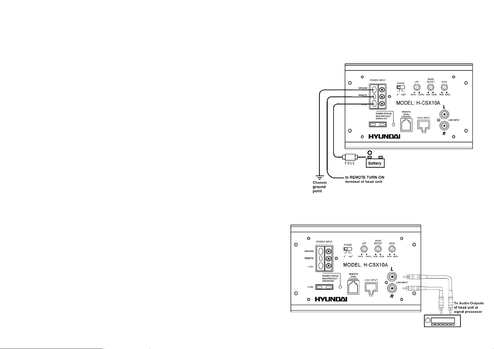
Power input terminal connecting
1. Connect the ground terminal to the closest point on the chassis of the vehicle. Keep this
ground wire to less than 39" (100 cm) in length. Use 8 gauge (or heavier) wire.
2. Connect the remote terminal to the remote output of the head unit using 16 gauge (or
heavier) wire.
3. Connect an empty fuse holder within 18" (45 cm) of the car battery, and run 8 gauge (or
heavier) cable from this fuse to the amplifier location. Check that the fuse holder is empty.
Then connect the fuse holder to the "BATT+" connection on the amplifier.
4. Connect all line inputs and outputs (if used) using high-quality cables. Connect all speakers,
following the diagrams in this manual. Be sure to observe proper polarity to avoid audio
phase problems.
5. Insert fuse into battery fuse holder.
6. Recheck all connections before powering up the subwoofer.
7. Set all level controls to minimum position, and set all crossover control/switches to the
desired frequency points.
8. Power up the head unit and the subwoofer. Then set the volume control on the head unit to
about 3/4 volume, and adjust the subwoofer's input level controls to just below the level of
distortion.
9. Further fine tuning of the various controls may be necessary to obtain best results.
Notes: Separate audio and power wiring to avoid interference.
All wires and connections must be insulated with electrical tape, and filter with
protective connector shields where ever possible.
Before replacing blown fuse check and verify that there is no short cut at all connections.
Low level input connecting
Low-level (RCA) input wiring is preferred for best audio performance. most trunk
or hatchback installations will require a 15-20 foot RCA cable, while pickup
trucks and under-seat installations will require a 6-12 foot RCA cable. Always use
a high quality cable.
Connecting scheme see on the pic. 2.
3
Pic. 1
Pic. 2
Page 4
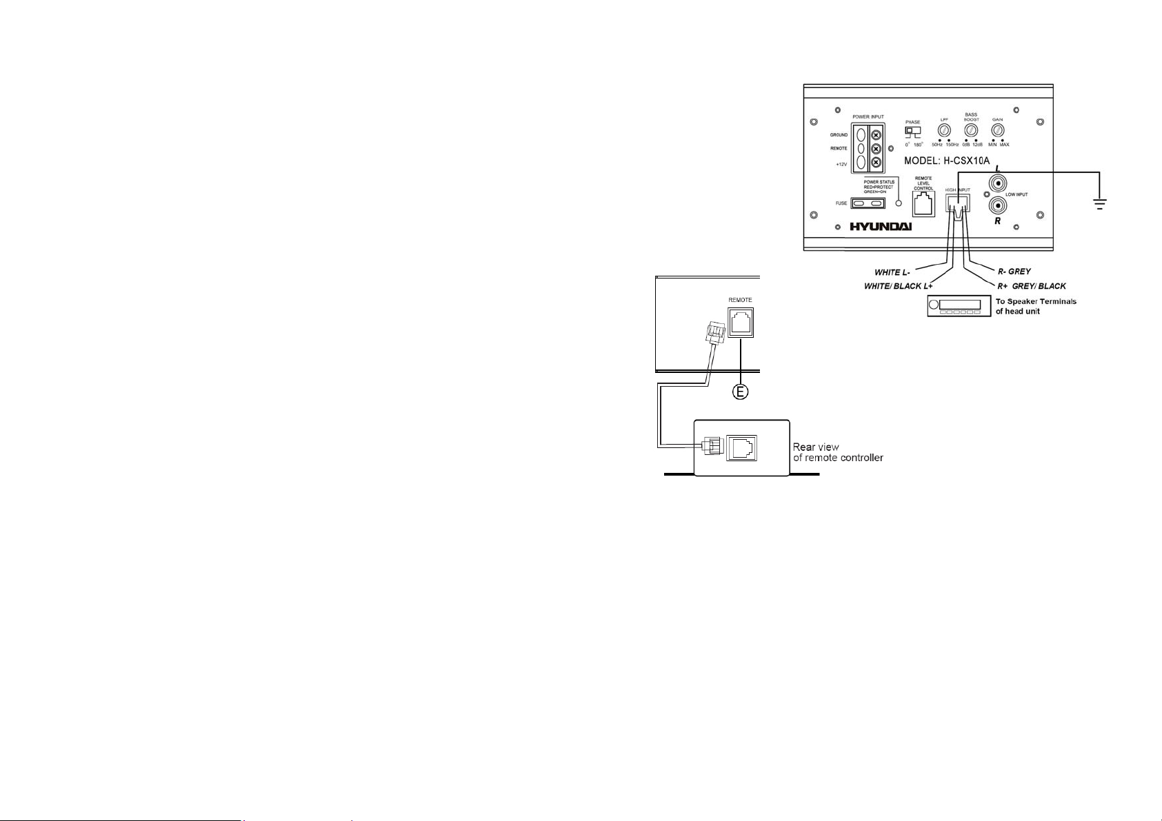
High level input connecting
The high level input(s) should only be used when your receiver lacks RCA outputs.
If the RCA outputs are not present, connect the speaker outputs from the receiver to the high level input
connector of the amplifier. Be sure to observe polarity to avoid audio phase problems.
Connecting scheme see on the pic. 3.
Note: Inputs may be high level (from the receiver's speaker) or low level (from special low level outputs).
Low level is preferred for best performance.
Attention: Use only the low level or high level input, do not use both at one time.
Remote control connecting
Connecting scheme see on the pic. 4.
Connect the remote control to REMOTE jack on subwoofer.
Fuse connecting
Power fuse protect both the amplifier and the electrical system of your car from
fault conditions. If you must replace a fuse in your HYUNDAI powered
subwoofer, use a fuse of exactly the same type and rating. Using a different
type or rating of fuse may result in damage to your amp or vehicle or cause a
fire.
Pic. 4
Pic. 3
4
Page 5

Functions and controls
1. Power terminals: GND (ground), REM, +12V.
2. PHASE switch
Use this switch to help compensate for time alignment problems in the system. Such
problems usually result from having the subwoofer at a different distance from the listener
than the other speakers in the system.
Changing woofer phase with the PHASE switch (0, 180 degrees).
3. LPF (Low Pass Filter) regulator
This control permits you define the frequency range you want the subwoofer amplifier to
receive. The subwoofer will reproduce all sound BELLOW the frequency you set.
If the rest of your system is weak on the mids, you may wish to set this control relatively
high. If the midrange is well covered by the rest of your system, you will probably want
the subwoofer to only receive lower frequency signal.
Adjust the low-pass crossover (50 – 150 Hz available).
4. BASS BOOST regulator
The bass boost feature will increase the sound level in the bass frequency.
Adjust the frequency of the bass control filter (0 – 12 dB of boost available).
5. GAIN regulator
After you have installed your system, turn this control to minimum.
Turn the head unit on (and the subwoofer will turn on via the remote connection). Turn the
head unit volume to about 2/3 full level.
Slowly turn up the subwoofer input gain control until you hear a small amount of distortion. Then reduce the level until the distortion is completely
gone. Level the control at this setting.
6. LED indicator
This bi-color LED glows green when power is on and no problems are present. If one of the protection circuits comes on, it will change to red.
5
Page 6

Troubleshooting
No sound
switched on
Abnormal distorted sound Input control level is too high. Adjust input LEVEL control.
The LED indicator is not
illuminated.
Short cut. Verify that there are no short
Grounding is wrong. Verify for proper grounding.
No signal input. Check if the audio cable is
The volume is minimum. Adjust the volume level.
There is no power to “REM”
jack when the radio is on.
The fuse has blown. Verify and replace blown fuse.
Check fuse in amplifier.
Verify connections are correct.
cut.
connected.
Check connections to radio. The amplifier can not be
Specification
Output power 500 W (Peak)
RMS 150 W @ 4 Ohm @ 100 Hz
Sensitivity 91 dB
Variable low pass 50 – 150 Hz
THD <0.4%
Input level 110 mV (RCA-Line-In), 0.5 V (Speaker input)
Power source DC 10 - 14,4 V Negative ground
Frequency response Input: 35 – 150 Hz
Bass Boost 0 - 12 dB @ 45 Hz
Phase 0º/180º
Fuse rating 25
Dimensions 400 x 310 x 240 mm
Weight 9.92 kg
6
Page 7

Особенности сабвуфера
• Фибро-армированный пластик
• 10-дюймовый сабвуфер из прессованной целлюлозы
• Блок питания на транзисторах Mosfet
• Защита от короткого замыкания, перегрева, перегрузки
• Индикация рабочего состояния
• Выносной пульт ДУ
• Подключение по высокому и низкому уровню напряжения
Аксессуары
Перед первым использованием проверьте комплектацию изделия.
• Проводной пульт управления
• Соединительный кабель
• Разъем высокоуровневого входа с проводом
• Клейкая лента
• Пластиковые стойки с шурупами
• Инструкция по применению
Установка сабвуфера и пульта управления
Внимание: Прежде, чем устанавливать сабвуфер и пульт управления, подключите их и протестируйте.
Установка сабвуфера: Выберите подходящее место в автомобиле для установки сабвуфера. Поскольку сабвуфер объемный и достаточно
много весит, рекомендуется устанавливать его в багажнике.
Отметьте место установки сабвуфера, просверлите отверстия для его крепежа. Используйте крупные болты для крепежа. После закрепления
сабвуфера пошатайте его, затем по необходимости закрепите более надежно.
Установка пульта управления: Выберите подходящее место для пульта управления, где он будет
легко доступен во время вождения. Используя отверстия в корпусе пульта, наметьте и просверлите
отверстия на крепежной поверхности, затем прикрепите пульт с помощью винтов (рис. 1).
Внимание:
• Убедитесь, что место установки подготовлено для сверления и прокладки проводов.
• Закрепите корпус сабвуфера так, чтобы он не перемещался во время езды.
• Не подвергайте сабвуфер перегреву и переохлаждению.
• Избегайте попадания внутрь влаги и механических предметов.
Рис.1
7
Page 8

Подключение
Следуйте всем инструкциям по сборке и установке, чтобы избежать короткого замыкания и быть уверенным в правильности подключения.
Перед подключением: Питающий и аудио кабели рекомендуется проложить отдельно друг от друга, чтобы избежать наводок.
Все провода и кабели должны быть изолированы.
Перед заменой предохранителя убедитесь в отсутствии короткого замыкания.
Подключение питания
1. Заземление: Подключение к корпусу автомобиля. Во избежание электромагнитных
шумов от системы зажигания сабвуфер необходимо подключить к металлической
поверхности корпуса автомобиля, используя болтовое соединение и обеспечив
хороший электрический контакт. Оставьте запас около 100 см по длине.
Используйте провод 8GA или толще.
2. Вход дистанционного включения: Подключите к проводу питания антенны или
специальному управляющему проводу - сабвуфер будет включаться вместе с
автомагнитолой.
Примечание: Если Ваша автомагнитола не имеет управляющего выхода (+12 В), вы
можете подключить этот провод к общему источнику питания, на котором появится +12
В, когда ключ в замке зажигания повернут во включенное положение.
3. Питание +12 В: К (+) Батареи: Подключите сабвуфер к положительной (+) клемме
аккумулятора. В целях повышения безопасности рекомендуется установить на
провод специальный предохранитель, который должен находиться в моторном
отсеке на расстоянии 45 см от аккумулятора. Проведите от автомобильного
аккумулятора кабель питания 8GA (или толще) к сабвуферу и поставьте на провод
пустую колбу предохранителя. Убедитесь, что колба пуста.
4. Подключите все линейные входы и выходы (если используются). Подключите все динамики. Соблюдайте полярность подключения во
избежание проблем с фазой сигнала.
5. Вставьте предохранитель в колбу.
Примечание: Предохранитель защищает сабвуфер и систему питания Вашего автомобиля от перегрузок. Если Вам необходимо заменить
предохранитель, используйте предохранитель такого же типа и номинала, в целях безопасности.
6. Проверьте все подключения, перед тем, как включить питание сабвуфера.
7. Установите все регуляторы на минимальный уровень, установите все переключатели кроссоверов на нужный уровень частот.
8. Включите питание головного устройства и сабвуфера. Затем установите уровень звука на головном устройстве на 3/4 и отрегулируйте
уровень входных сигналов сабвуфера так, чтобы не было искажений звука.
9. При необходимости осуществите точную настройку регуляторов для получения звука наилучшего качества.
Рис. 2
8
Page 9

Подключение с использованием линейного выхода магнитолы (Line out)
Подключение с использованием линейного входа – это вывод звука напрямую
с магнитолы на сабвуфер, при этом обеспечивается наилучшее качество звука с
минимальными искажениями. Для подключения разъема LINE OUT Вашей
автомагнитолы к RCA-входу сабвуфера используйте защищенный стерео аудио
кабель с разъемами RCA на концах. Схема приведена на рис 3.
Подключение по схеме высокоуровневого сигнала
Схема подключения приведена на рис. 4.
Используйте высокоуровневый вход в том случае, когда ваша магнитола не имеет
линейного выхода (Line out). В этом случае сигнал берется непосредственно с выводов
динамиков.
Примечание: Сабвуфер оснащен высокоуровневым и низкоуровневым входами. Не
используйте одновременно оба входа.
Подключение пульта управления
Схема подключения изображена на рис. 5.
Рис. 5
Рис 3.
Рис. 4
9
Page 10

Работа с устройством
1. Разъемы питания: «земля», управление, +12В
2. Переключатель фазы сигнала
При помощи этого переключателя слушатель на слух может подстроить фазу
низких частот сабвуфера и сигнала из динамиков. Это необходимо чаще всего
тогда, когда сабвуфер установлен достаточно далеко от слушателя и других
динамиков. Доступны значения от 0 до 180 гр.
3. Фильтр LPF
Фильтр низких частот (LPF) позволяет установить требуемую частоту среза
подаваемого сигнала на динамическую головку. Доступны значения от 50 до 150
Гц.
4. Регулятор усиления низких частот
Этим регулятором есть возможность искусственно повысить отдачу низких частот,
в пределах 0 – 12 дБ, на фиксированной частоте, установленной изготовителем.
5. Регулятор общего усиления.
Потенциометр LEVEL предназначен для установки требуемой чувствительности
входного сигнала. Изначально потенциометр на корпусе сабвуфера рекомендуется
установить в положение, приблизительно 75 % от максимального уровня и
убедиться в отсутствии искажений.
Кроме этого, оперативно подстроить уровень входного сигнала можно с выносного пульта ДУ. Т.к. уровень записи низких частот
различный у разных источников звука, скажем, диска или приемника, то возможность настроить требуемое звучание с водительского
места будет очень полезной.
6. Индикатор работы усилителя
Зеленое свечение означает нормальный режим работы. Если загорается красный светодиод, то это означает, что сработала система
электронной защиты. Следует принять меры к устранению замыкания или перегрузки.
10
Page 11

Неполадки и их устранение
Нет звука
Возможное короткое замыкание Убедитесь в отсутствии короткого замыкания
Неправильное заземление Проверьте заземление
Нет сигнала Проверьте подключение аудио кабеля
Низкий уровень громкости Отрегулируйте уровень громкости
Когда автомагнитола включена,
быть включен
Звук искажен Уровень входного сигнала
нет сигнала на разъем REМ
Сгорел предохранитель Проверьте и замените сгоревший предохранитель
слишком высокий
Проверьте предохранитель, при необходимости замените его. Индикатор не горит
Проверьте правильность всех подключений
Проверьте подключение к автомагнитоле Сабвуфер не может
Отрегулируйте уровень входного сигнала с помощью
регулятора LEVEL
Технические характеристики
Выходная мощность 500 Вт (максимальная)
RMS 150 Вт @ 4 Ом @ 100 Гц
Чувствительность 91 Дб
Регулируемый фильтр НЧ 50 - 150 Гц
THD < 0.4%
Чувствительность входа 110 мВ (линейный вход RCA), 0.5 В (вход динамиков)
Источник питания DC 10 В - 14,4 В отрицательный
Диапазон воспроизводимых частот Вход 35 – 150 Гц
Усиление НЧ 0 – 12 дБ @ 45 Гц
Переключатель фазы 0º/180º
Номинал предохранителя 25
Размер 400 x 310 x 240 мм
Вес 9.92 кг
11
 Loading...