How it Works
Log In / Sign Up
Buy Points
How it Works
FAQ
Contact Us
Questions and Suggestions
Users
HYUNDAI
Loading...
E
Elantra-GT 2014
2
Elantra Touring 2012
3
Elantra Touring (2013)
Elantra UD 2014
Entourage
ENTOURAGE (2007)
2
ENTOURAGE (2008)
2
Entourage (2013)
EON
Eon 2015
Eon 2016
EP 100W
3
EP 110 W
4
EP 200W
EP 201 E
EP 300E
3
EP 300W
3
EP 310 E
3
EP 310 W
4
Equos (2015)
EQUUS
4
EQUUS (2011)
4
Equus 2012
2
Equus 2013
4
Equus (2014)
4
Equus 2015
2
EQUUS (2016)
4
Equus Blue Link 2015
Equus II (2009)
Equus II (2013)
Equus II 2013 — 2016
Equus SIGNATURE (2014)
Equussignature 2016
Equus ULTIMATE (2014)
Equus VI 2009
Equus VI 2011
Equus VI 2012
Equus VI 2013
Equus VI 2015
EQUUS мультимедийный центр
Eqwo Black HO-5
Eqwo HO-4
Ertzo SWS5
Excel 1986
Excel (1987)
Excel 1991
Excel 1992
Excel 1993
F
F4GE9454J*J604
F4GE9484F*J608
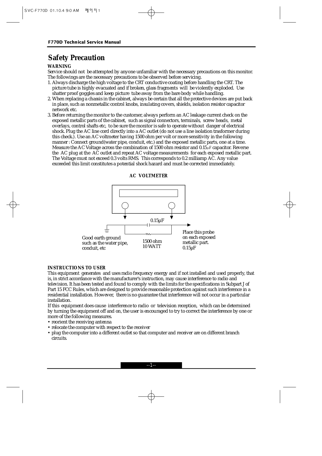
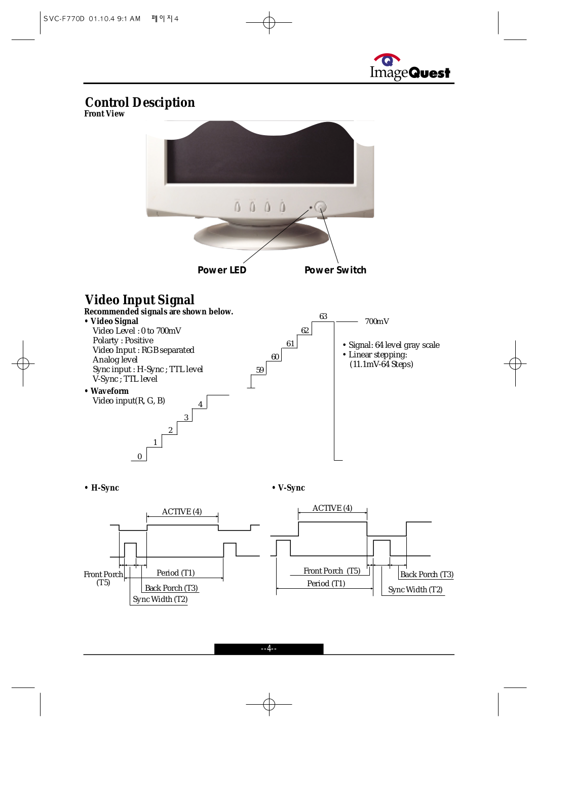
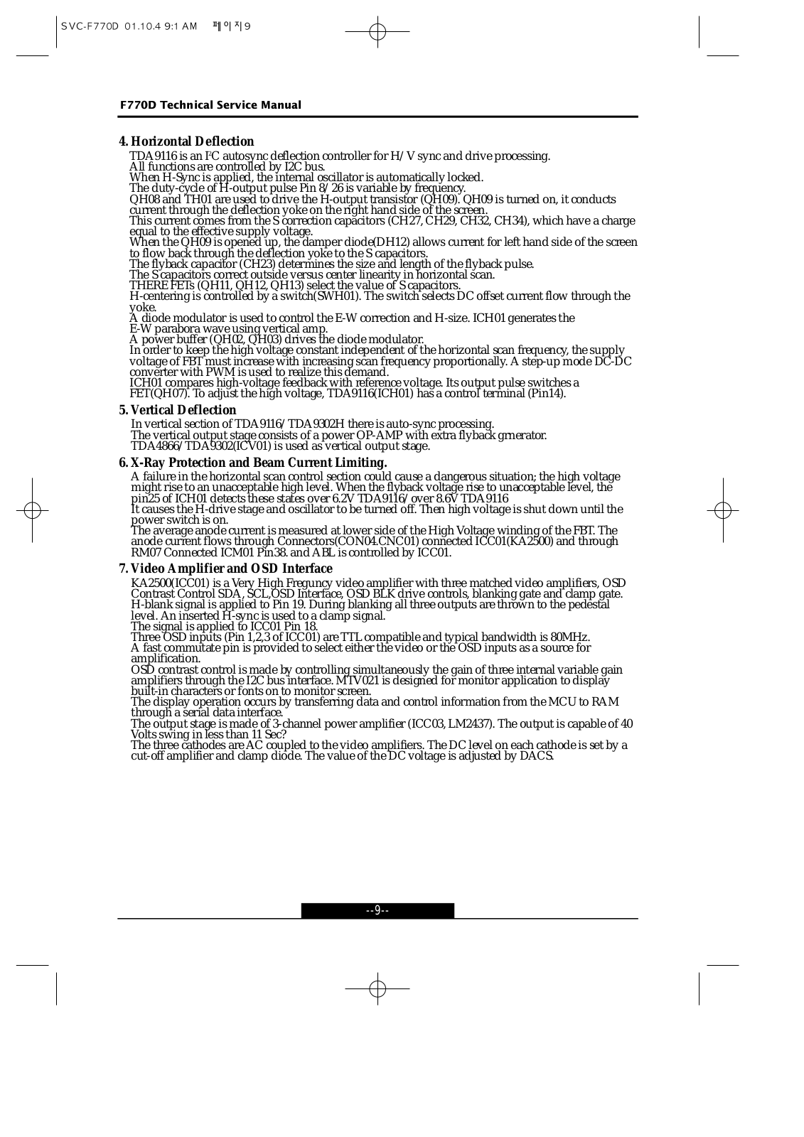
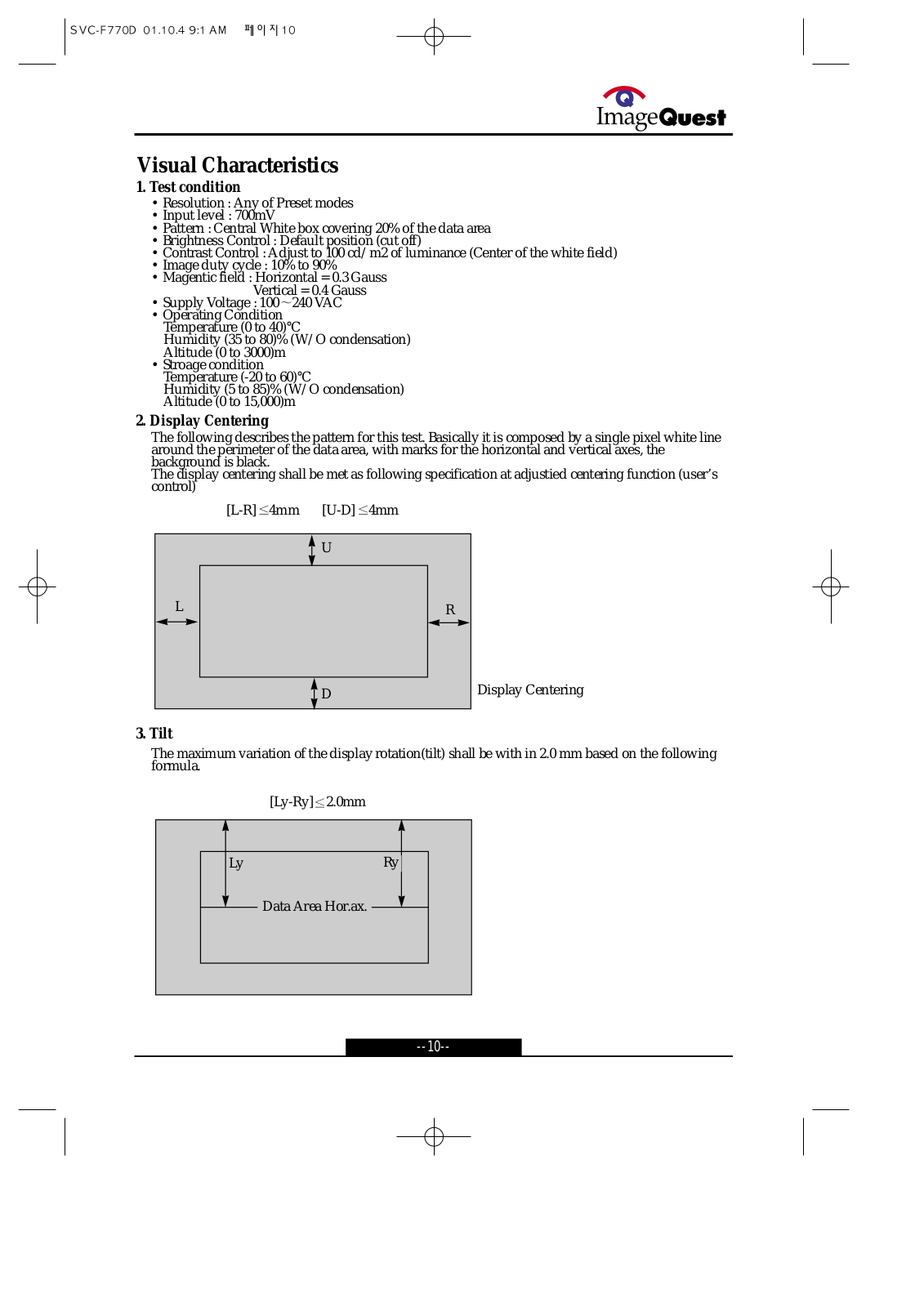
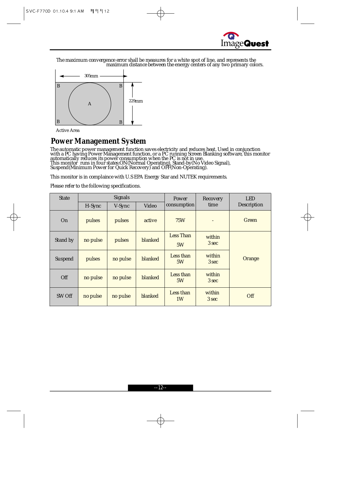
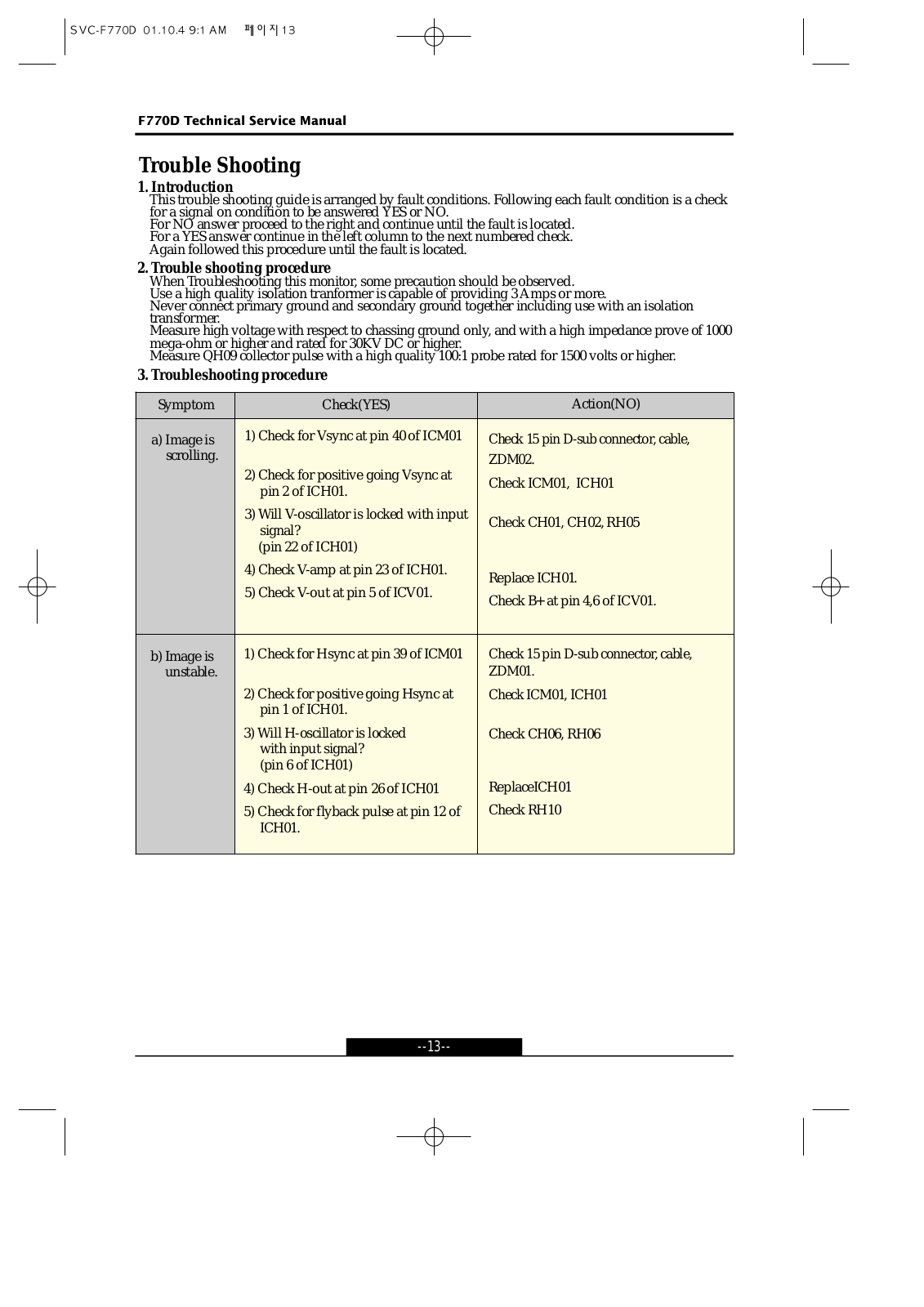
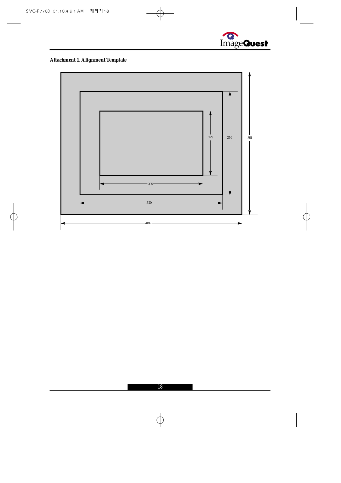
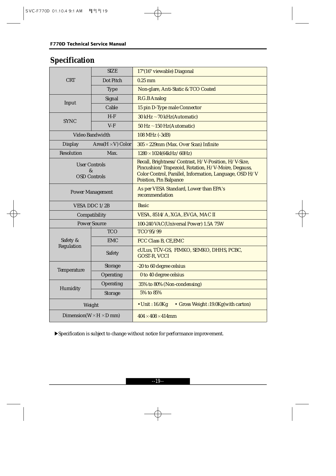
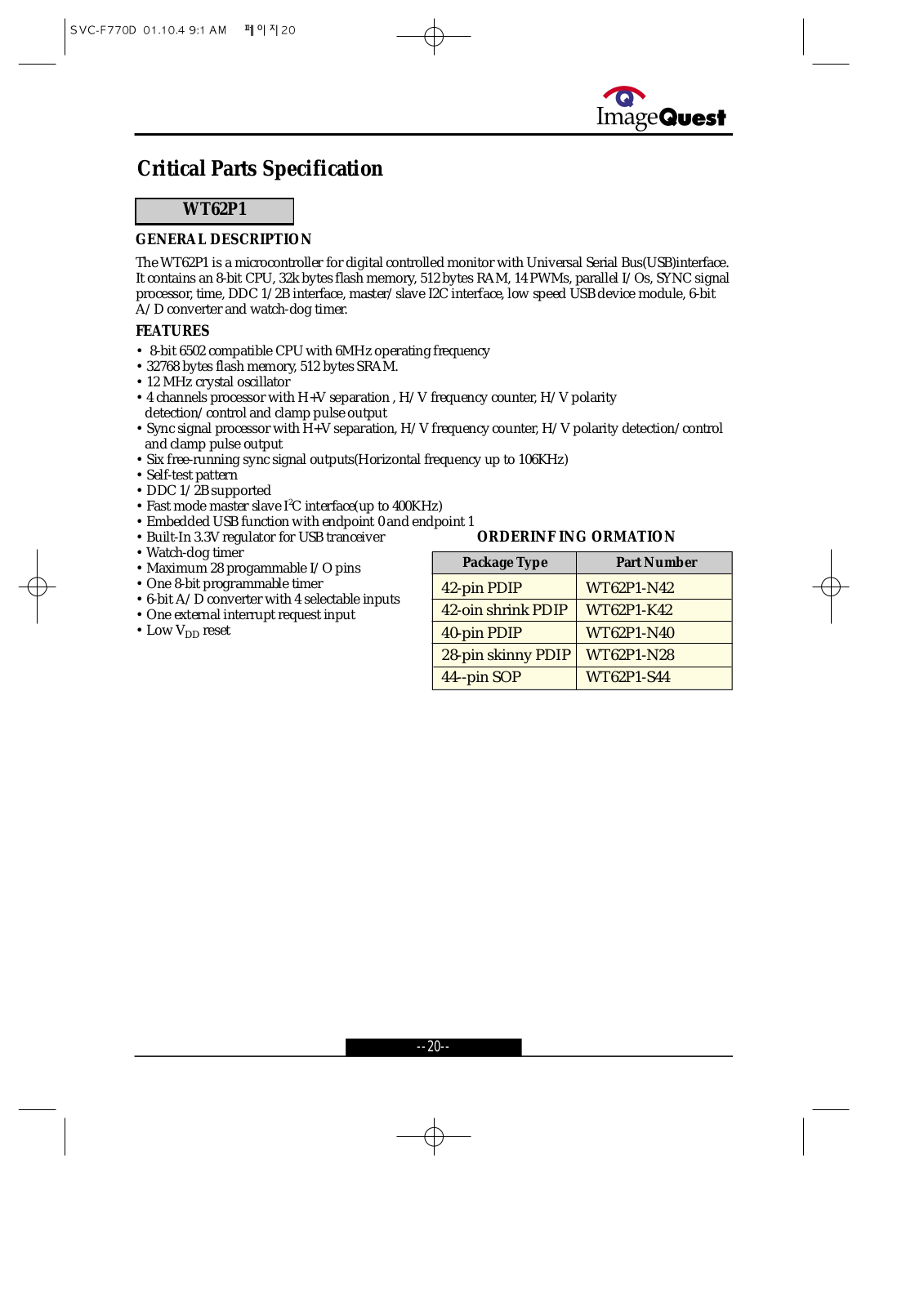
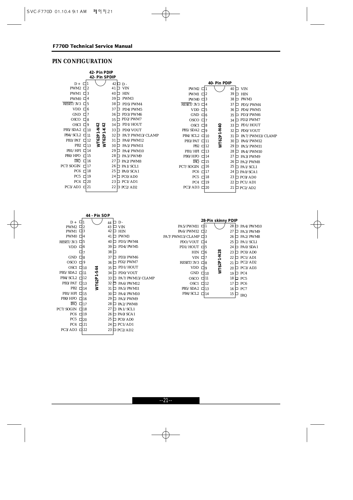
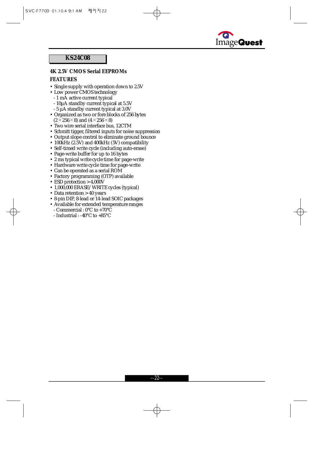
F770D
FAN30
4
FAN40
3
FD-01
FD505
FH1
FH3
FL 22111
FL 22211 SMART
2
FL 22262 CAR
FL 22272
FL 24195
FL 24285 SMART
2
FL 32411 SMART
FL 32515
FL 32S367 SMART
FL 39272
FL 39382 SMART
FL 39S372
FL 40111
2
FL 40211
FL 40211 SMART
FL 40272
FL 40S311 SMART
FL 40S367 SMART
FL 40S372 SMART
2
FL 42267 SMART
FL 48272
FL 50272
FL 50S372
FLA 4001 FE
FLA 5501 FE
Flamsy HU4M
FLE 32411 SMART
FLE 32S586 SMART
FLE 39382 SMART
FLE 4002 FE
FLE 40382 SMART
FLE 40586 SMART
FLE 40S586 SMART
FLE 42382 SMART
FLE 4802 FE
FLE 50211 SMART
FLE50S372SMART
FLN 22T111
FLN 22TS211
FLN 22TS382 SMART
2
FLN 24T439
FLN 32T339
FLN 32TS439 SMART
Loading...
Loading...
Nothing found
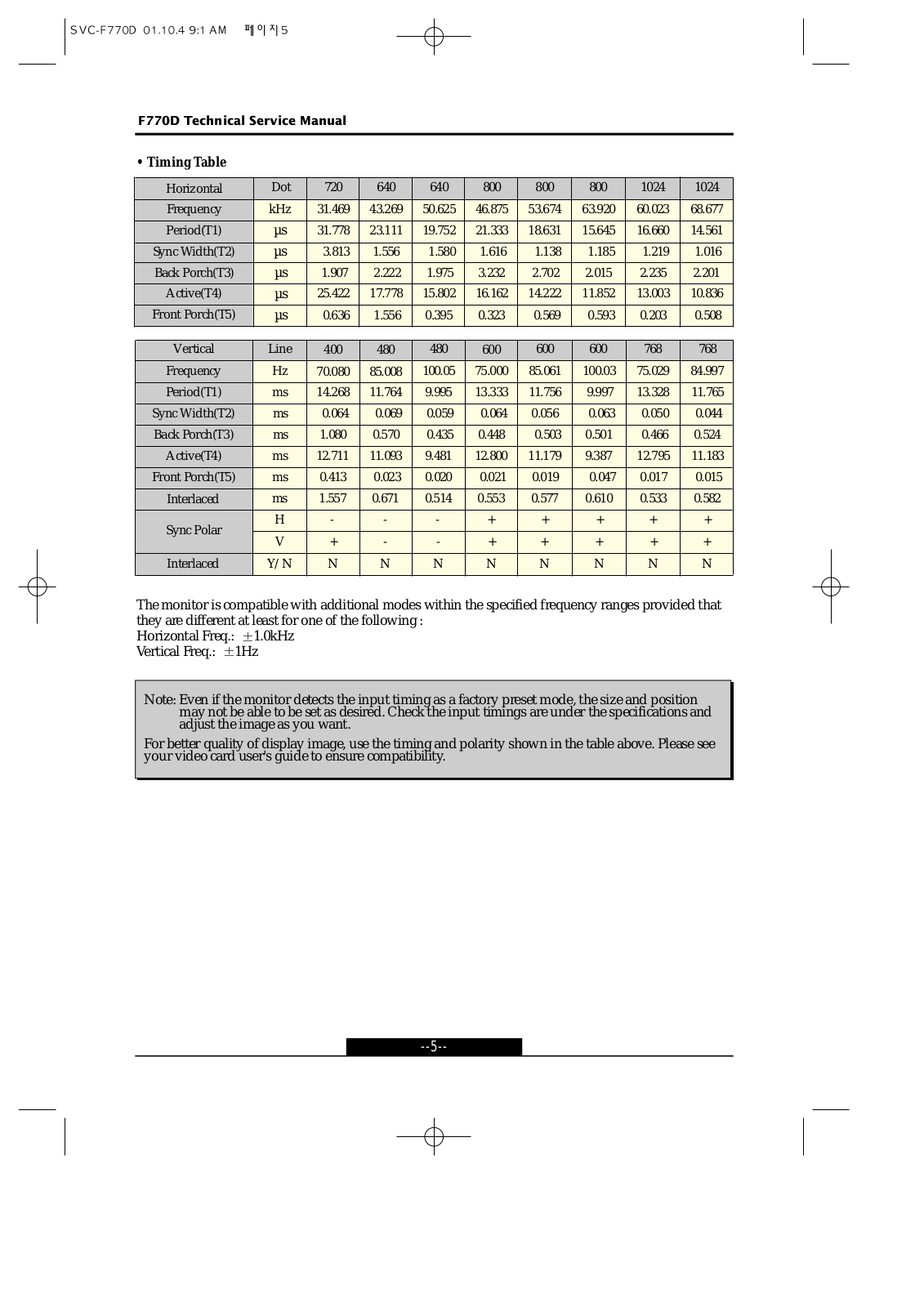
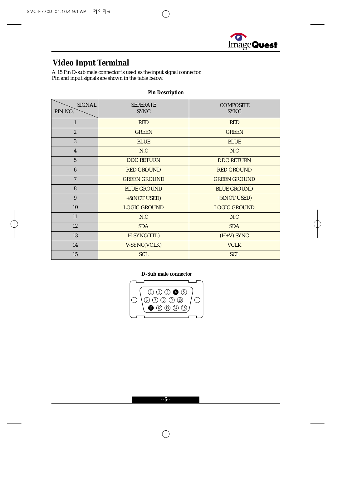
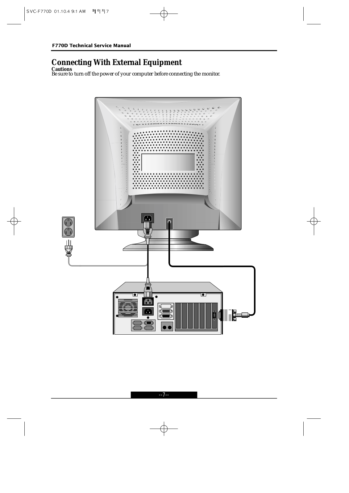
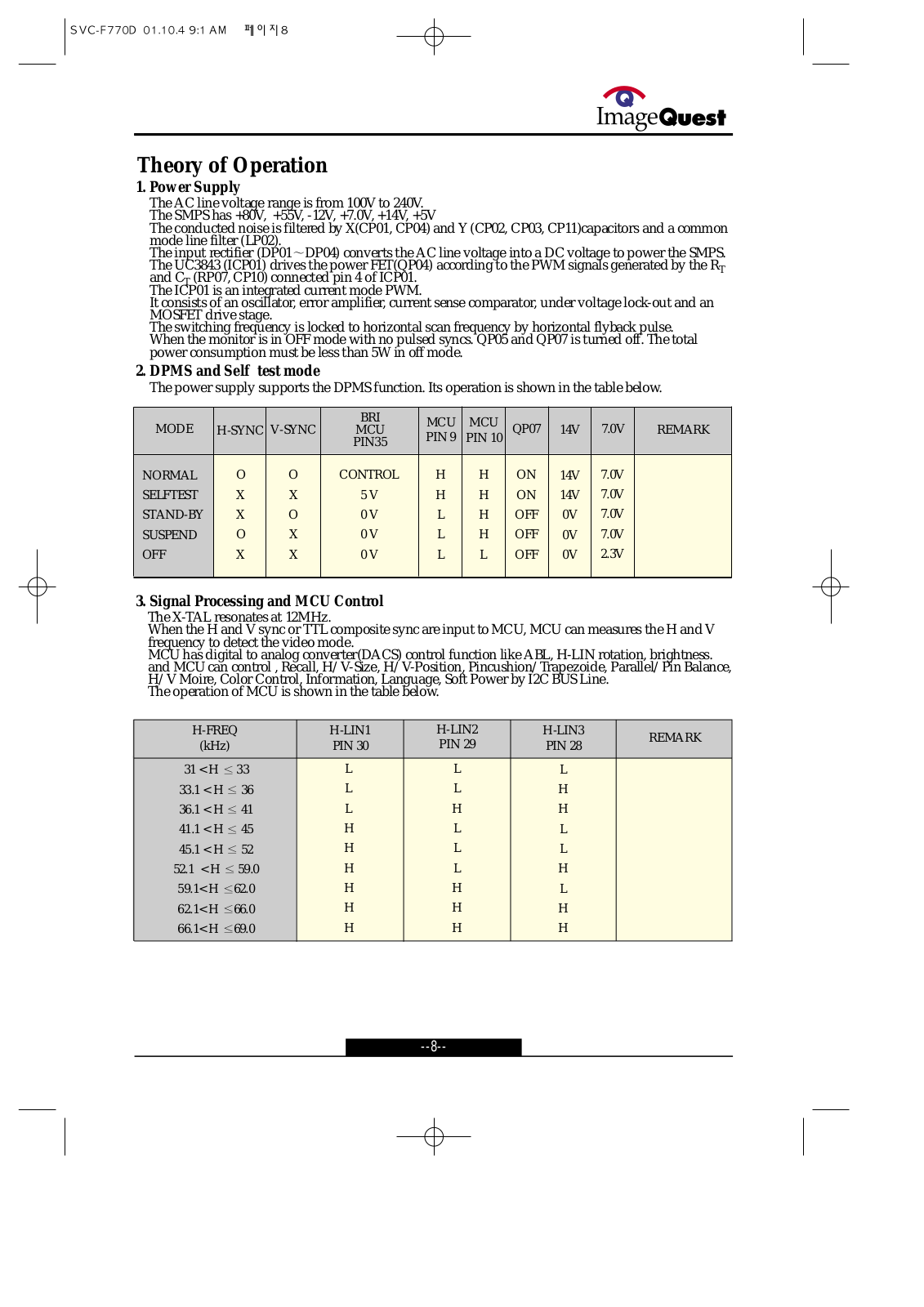
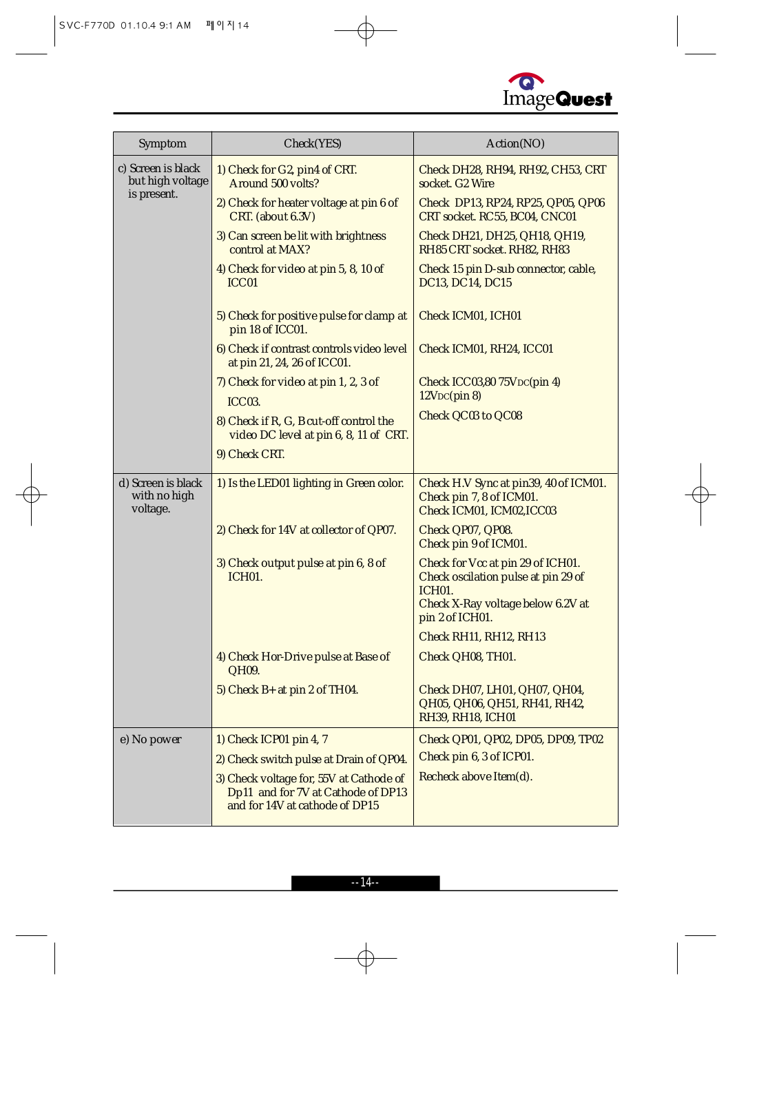
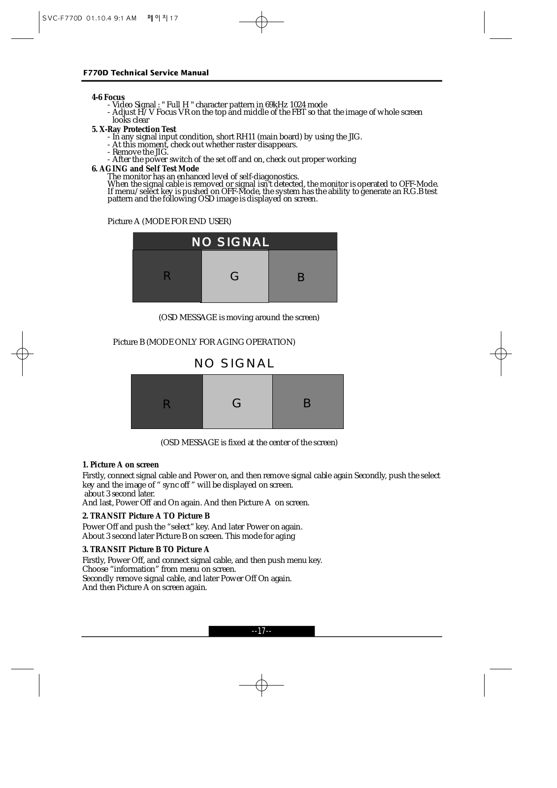
F770D
service manual
75 pgs
4.43 Mb
0
Table of contents
Loading...
HYUNDAI F770D service manual
...
HYUNDAI service manual
Download
Specifications and Main Features
Frequently Asked Questions
User Manual
Download
Loading...
+
52
hidden pages
Unhide
You need points to download manuals.
1 point = 1 manual.
You can buy points or you can get point for every manual you upload.
Buy points
Upload your manuals
 Loading...