

Page 1

ENGINE
ELECTRICAL
SYSTEM
Return to Main Table of Contents
GENERAL
...............................................................
2
IGNITION SYSTEM
CHARGING SYSTEM
STARTING SYSTEM
CRUISE CONTROL SYSTEM
................................................
................................................
.............................................
.................................
4
13
29
38
Page 2

27-2
GENERAL
SPECIFICATIONS
Distributor
GENERAL
Type
Advance mechanism
Ignition order
Ignition coil
Type
Primary coil resistance
Secondary coil resistance
Spark plug
Type
NGK
Champion
Plug gap
Contact pointless type
Controlled by engine control module
1-3-4-2
Mold dual-coil
0.8 ± 0.09
12.1 ± 1.8
BPR6ES-11
RN9YC4
1.0-1.1 mm (0.039-0.043 in.)
Start motor
Type
Voltage
output
No-load characteristics
Terminal voltage
Amperage
Speed
Number of pinion teeth
Pinion gap
Reduction drive (with planetary gear)
12v
1.2KW
11v
90A
3,000 RPM
8
052.0 mm (0.0197-0.079 in.)
Page 3

Generator
GENERAL
Type
Rated output
Voltage regulator type
Regulator setting voltage
Temperature compensation
Battery
Type
Ampere hours (5HR)
(20HR)
Cold cranking [at -17.8oC(0oF)]
Reserve capacity
Specific gravity [at 25oC(77oF)]
NOTE
COLD CRANKING AMPERAGE is the amperage a battery can deliver for 30 seconds and maintain a terminal
voltage of 7.2 or greater at a specified temperature.
RESERVE CAPACITY RATING is the amount of time a battery can deliver 25A and maintain a minimum terminal
voltage of 10.5 at 26.7o (80°F).
Battery voltage sensing
13.5 V
Electronic built-in type
14.4 ± 0.3V
-10 ± 3 mV/oC
GOAH-B
48 Ah or more
60 Ah or more
420 A or more
92 min.
1:270 ± 0.01
Page 4
27-4
IGNITION SYSTEM
IGNITION SYSTEM
GENERAL INFORMATION
Ignition timing is controlled by the electronic control ignition timing
system. The ignition timing data for the engine operation conditions
are programmed in the memory of the engine control module
(ECM).
The engine conditions (speed, load, warm-up condition, etc.) are
detected by the various sensors. Based upon these sensor signals
and the ignition timing data, signals to interrupt the primary current
are sent to the power transistor. The ignition coil is activated, and
timing is controlled at the optimum point.
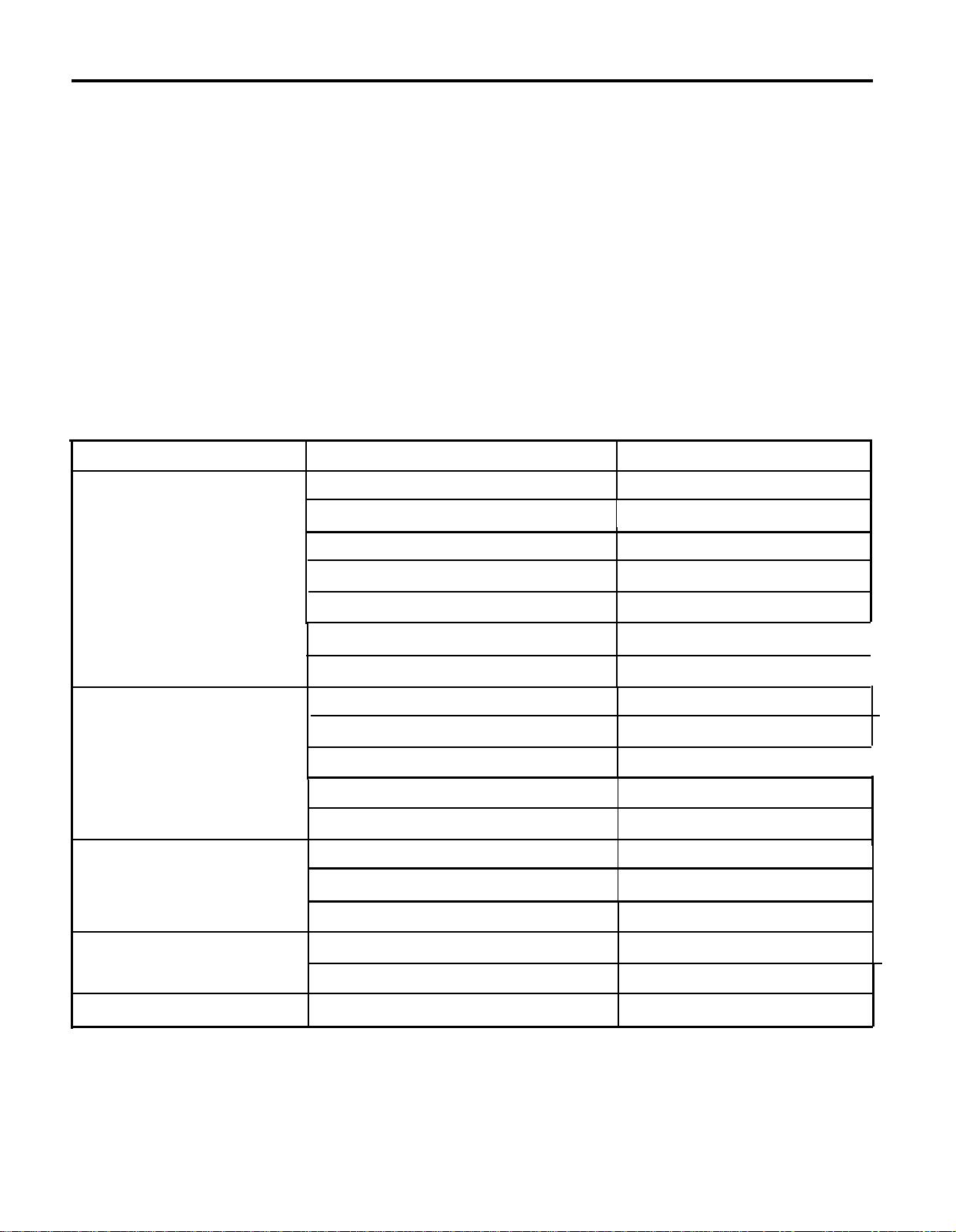
TROUBLE SHOOTING
Trouble condition
Engine will not start or is
hard to start. (Cranks OK)
Rough idle or stalls
Engine hesitates/poor
acceleration
Probable cause
Incorrect ignition timingIgnition coil faulty
Power transistor faulty
Crankshaft position sensor faulty
High tension cable faulty
Spark plugs faulty
lgnition wiring disconnected or broken
Spark plugs faulty
Ignition wiring faulty
Incorrect ignition timing
Ignition coil faulty
Power transistor faulty
Spark plugs faulty
Ignition wiring faulty
Remedy
Adjust ignition timing
Inspect ignition coil
Inspect power transistor
Replace crankshaft position sensor
Inspect high tension cable
Replace plugs
Inspect wiring
Replace plugs
Inspect wiring
Adjust ignition timing
Inspect ignition coil
Inspect power transistor
Replace plugs
Inspect wiring
I
I
I
Poor mileage
Engine overheats
Incorrect ignition timing
Spark plugs faulty
Incorrect ignition timing
Incorrect ignition timing
Adjust timing
Replace plugs
Adjust ignition timing
Adjust ignition timing
Page 5
IGNITION SYSTEM
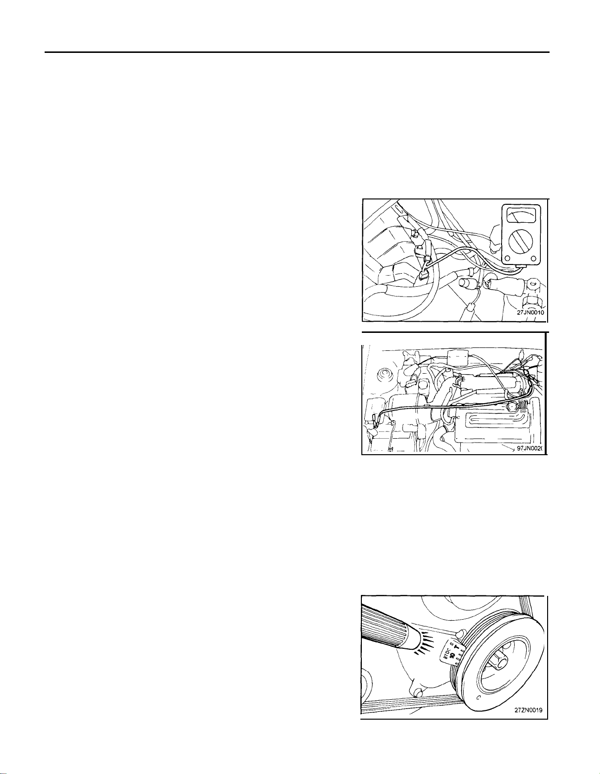
IGNITION TIMING
Adjustment conditions:
Coolant temperature: 80.95°C (170-205°F)
Lamps, cooling fan, and all accessories: Off
Transaxle range : Neutral (N or P for A/T)
Parking brake : ON
Steering wheel : Neutral position
Adjustment Procedures
1.
Install a tachometer and a timing light.
2.
Run the engine for more than 5 seconds at an engine speed of
2,000 to 3,000 rpm.
Run the engine at idle for 2 minutes.
3.
Read the idling rpm. If it is not within the specified value, check
the idle speed control system.
Idle speed :
Refer to 31 GROUP - Idle speed adjustment section.
700 ± 100 rpm (For 1.6L)
700 ± 100 rpm (For 1.8L)
27-5
NOTE
1) Do not use the scan tool.
If tested with the scan tool connected to the data link
connector, the ignition timing will not be the basic
timing, but be ordinary timing.
2) The engine speed indicated is a second of actual speed.
In other words, the reading of the tachometer times 2 is
actual speed.
4.
Ground the ignition timing adjustment terminal.
5.
Check the basic ignition timing.
Basic ignition timing : 5o ± 2o BTDC (at idle)
6.
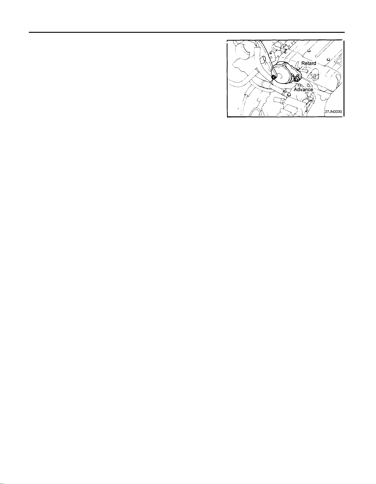
If the timing is incorrect, loosen the crankshaft position sensor
mounting nut, and rotate the crankshaft position sensor until the
timing is correct.
NOTE
The ignition timing will be retarded, if the crankshaft
position sensor is turned to the left and advanced if it is
turned to the right.
Page 6
27-6
7. After adjustment, securely tighten the mounting nut.
Tightening torque : 10-13Nm (100-130 kg.cm, 7-9 Ib.ft)
NOTE
Be careful, when tightening the nut, that the crankshaft
position sensor does not move.
8. Stop the engine.
9.
Disconnect the lead wire connected at step 4.
10. Start and run the engine at curb idle speed.
11. Check to be sure that the idling ignition timing is the correct
timing.
Actual ignition timing :
NOTE
-1.
Actual ignition timing may vary, depending on the
control mode of the engine control module. In such a
case, re-check the basic ignition timing. If there is no
deviation, the ignition timing is functioning normally.
2.
At high altitudes more than approximately (2,300
ft.) above sea level, the actual ignition timing is farther
advanced to ensure good combustion.
8o BTDC (For 1.6L)
14o BTDC (For 1.8L)
IGNITION SYSTEM
Page 7
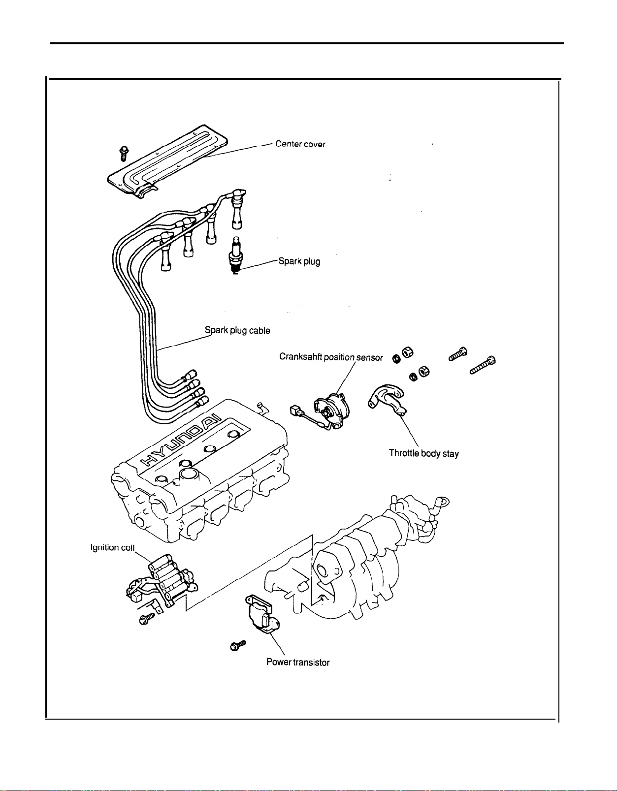
REMOVAL AND INSTALLATION
IGNITION SYSTEM
27-7
Page 8
27-8
IGNITION SYSTEM
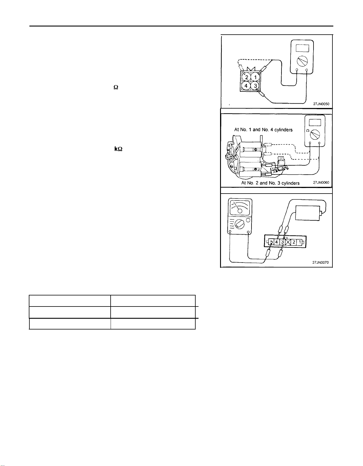
IGNITION COIL
Measurement of the primary coil resistance
Measure the resistance between connector terminals 3 and 1
1.
(the coils at the No. 1 and No. 4 cylinder sides) of the ignition
coil, and between terminals 3 and 2 (the coils at the No. 2 and
No. 3 cylinder sides).
Standard value: 0.77 - 0.95
Measurement of the secondary coil resistance
Measure the resistance between the high-voltage terminal for
1.
the No. 1 and No. 4 cylinders, and between the high-voltage
terminals for the No. 2 and No. 3 cylinders.
- Standard value: 10.3 - 13.9
CAUTION
Be sure, when measuring the resistance of the secondary
coil, to disconnect the connector of the ignition coil.
POWER TRANSISTOR
NOTE
An analog-type ammeter should be used.
Power transistor for coil No. 1 and No. 4 cylinders
Connect the negative (-) terminal of the 1.5V power supply to
1.
terminal No.3 of the power transistor; then check whether there
is continuity between terminal No.5 and terminal No.3 when
terminal No.4 and the positive (+) terminal are connected and
disconnected.
NOTE
Connect the negative (-) probe of the ammeter to terminal
No.5.
Terminal 4 and (+) terminal
Connected
Disconnected
Terminal 5 and terminal 3
Continuity
No continuity
Page 9
IGNITION SYSTEM
27-9
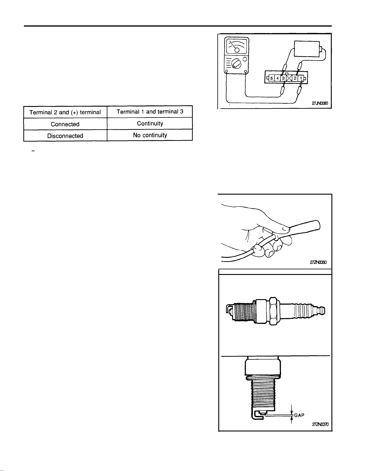
Power transistor for coil No.2 and No.3 cylinders
1.
Connect the negative (-) terminal of the 1.5V power supply to
terminal No.3 of the power transistor; then check whether there
is continuity between terminal No.1 and terminal No.3 when
terminal No.2 and the positive (+) terminal are connected and
disconnected.
NOTE
Connect the negative (-) probe of the ammeter to terminal
No.1
If the problem is still evident after checking as described above,
replace the power transistor.
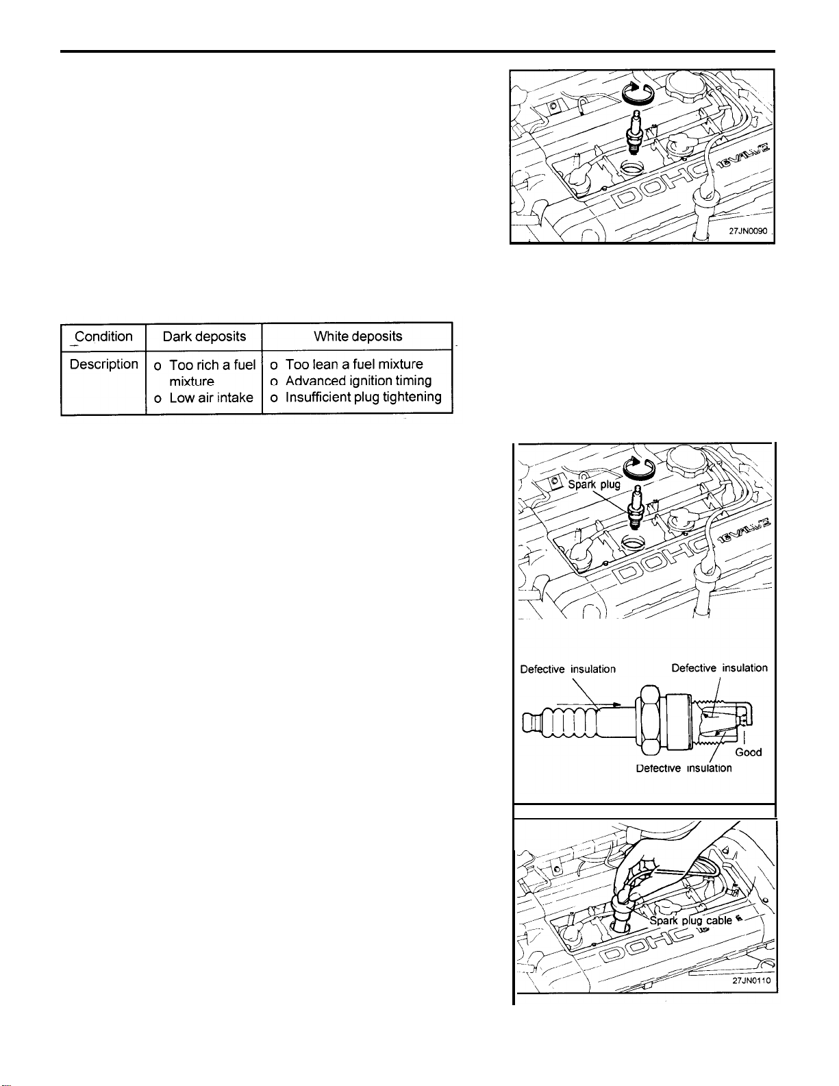
CHECKING SPARK PLUG
Inspection and Cleaning
1.
Disconnect the spark plug cable from the spark plug.
NOTE
Pull on the spark plug cable boot when removing the spark
plug cable, not the cable, as it may be damaged.
2.
Using spark plug wrench, remove all of the spark plugs from the
cylinder head.
NOTE
Take care not to allow contaminants to enter through the
spark plug holes.
3.
Check the spark plugs for the following:
1) Broken insulator
2) Worn electrode
3) Carbon deposits
4) Damaged or broken gasket
5)
Condition of the porcelain insulator at the tip of the sparkplug
4.
Check the spark plug gap using a wire gap gauge, and adjust
if necessary.
Standard value: 1.0-1.1 mm (0.039-0.043 in.)
Page 10
27-10
Re-insert the spark plug and tighten to the specified torque.
5.
If it is over torqued, damage to the threaded portion of cylinder
head might result.
Spark plug: 20-30 Nm (204-306 kg.cm, 15-21 Ib.ft)
Analyzing Spark Plug
Engine conditions can be analyzed by the tip deposits near the
electrode.
IGNITION SYSTEM
SPARK PLUG TEST
1.
Remove the spark plug and connect to the spark plug cable.
2.
Ground the spark plug outer electrode, and crank the engine.
3.
Check to be sure that there is an electrical discharge between
the electrodes at this time.
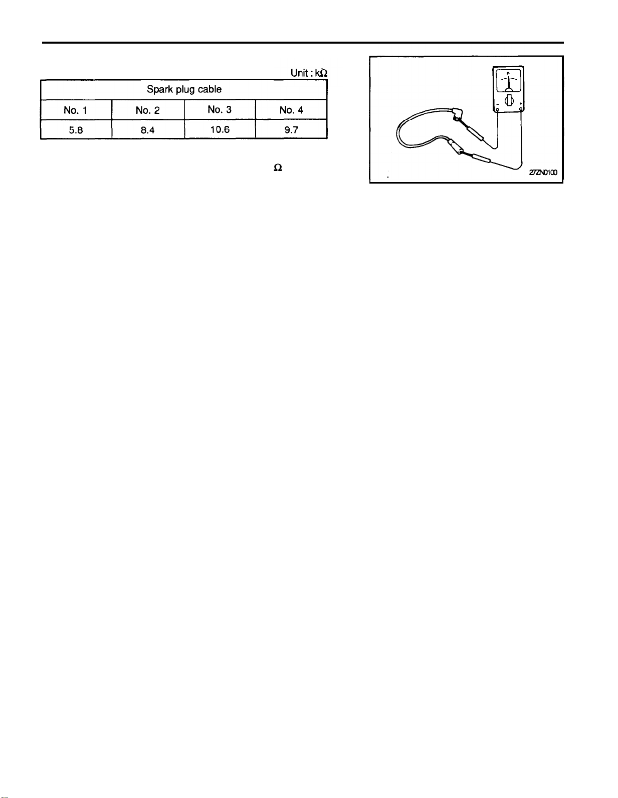
SPARK PLUG CABLES TEST
1.
Disconnect, one at a time each of the spark plug cables while
the engine is idling to check whether the engine’s running
performance changes or not.
Caution
Wear rubber gloves while doing so.
If the engine performance does not change, check the resis-
2.
tance of the spark plug, and check the spark plug itself.
3.
Check the cap and outer shell for cracks.
Page 11
IGNITION SYSTEM
4. Measure the resistance.
NOTE
Resistance should not be higher than 10,000 per foot
of cable. If resistance is higher, replace the cable.
27-11
Page 12
27-12
IGNITION SYSTEM
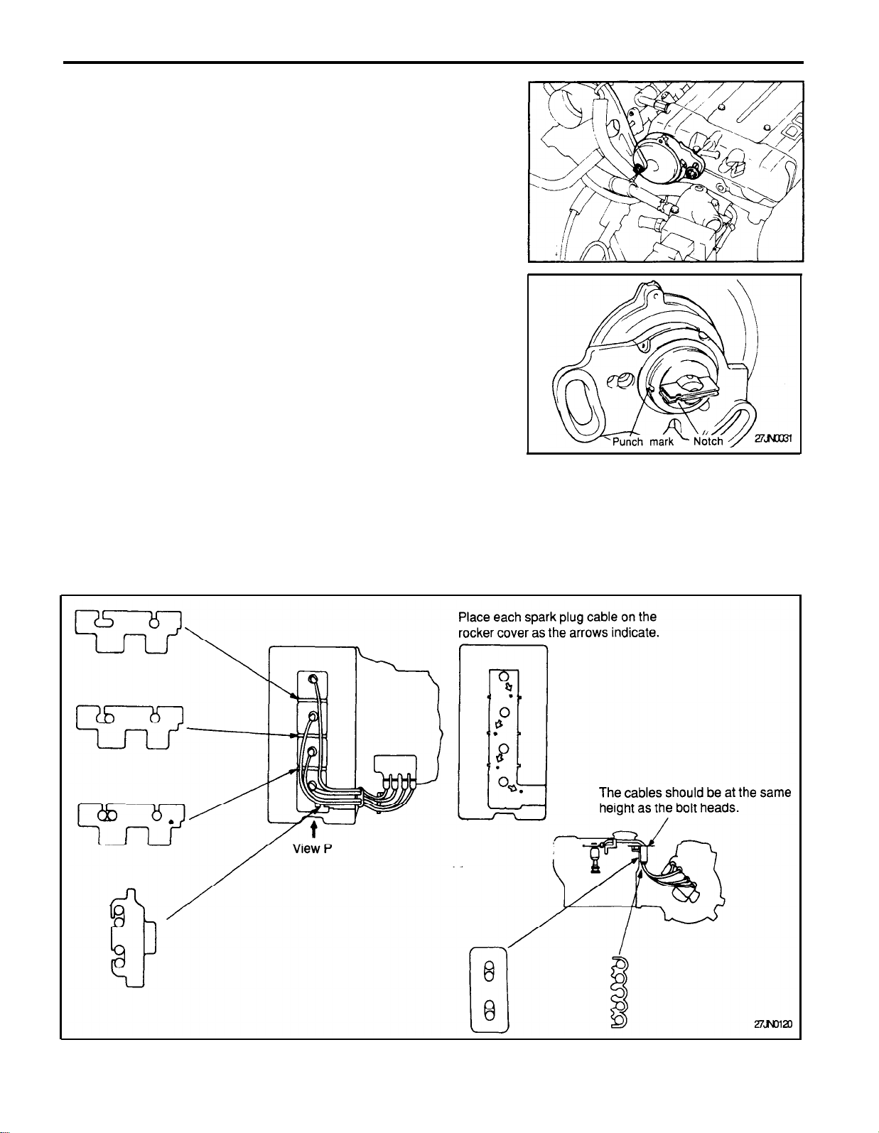
CRANKSHAFT POSITION SENSOR
1. Remove the battery ground cable
2.
Remove the crankshaft position sensor mounting bolt (2 EA).
3.
Pull out the crankshaft position sensor from cylinder head.
4.
Turn the crankshaft so that the No. 1 cylinder is at top dead
center.
5.
Align the punch mark on the crankshaft position sensor housing
with the notch in plate.
6.
Install the crankshaft position Sensor on the cylinder head.
INSTALLATION OF SPARK PLUG CABLE
Improper arrangement of spark plug cables will induce voltage
between the cables, causing miss firing and developing a surge at
acceleration in high-speed operation.
Therefore, be careful to arrange the spark plug cables properly as
shown in the illustration.
Page 13
CHARGING SYSTEM
CHARGING SYSTEM
GENERAL INFORMATION
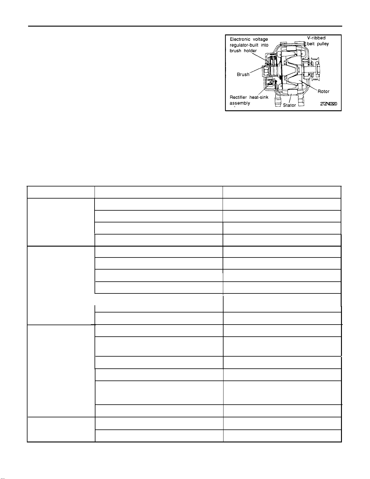
The charging system includes a battery, an generator with a built-
in regulator, and the charging indicator light and wires. The generator
has six built-in diodes (three positive and three negative), each
rectifying AC current to DC current. Therefore, DC current appears
at generator “B” terminal.
In addition, the charging voltage of this generator is regulated by the
battery voltage detection system. The main components of the
generator are the rotor, stator, rectifier, capacitor, brushes, bearings and V-ribbed belt pulley. The brush holder contains a built-in
electronic voltage regulator.
TROUBLESHOOTING
27-13
Symptom
Charging warning
indicator does not
light with ignition
switch “ON” and
engine off.
Charging warning
indicator does not
go out with engine
running.
(Battery requires
frequent recharging).
Discharge battery.
Probable cause
Fuse blown.
Bulb burned out.
Wiring connection loose.
Electronic voltage regulator faulty.
Drive belt loose or worn.
Battery cables loose, corroded or worn.
Fuse blown.
Fusible link blown.
Electronic voltage regulator or generator
faulty.
Wiring faulty.
Drive belt loose or worn.
Wiring connection loose or open circuit.
Fusible link blown.
Remedy
Check fuses.
Replace bulb.
Tighten loose connections.
Replace voltage regulator.
Adjust tension or replace drive belt.
Repair or replace cables.
Check fuses.
Replace fusible link.
Test generator.
Repair wiring.
Adjust tension or replace drive belt.
Tighten loose connection or repair
wiring.
Replace fusible link.
Overcharge
Poor grounding.
Electronic voltage regulator or generator
faulty.
Worn battery
Electronic voltage regulator faulty
Voltage sensing wire faulty
Repair.
Test generator.
Replace battery.
Replace voltage regulator.
Repair wire.
Page 14
27-14
CHARGING SYSTEM
INSPECTION OF CHARGING SYSTEM
VOLTAGE DROP TEST OF GENERATOR OUTPUT
WIRE
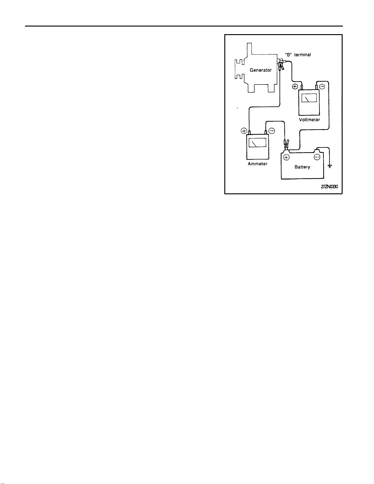
This test determines whether or not the wiring between the generator
“B” terminal and the battery (+) terminal is good.
Preparation
1. Turn the ignition switch to “OFF”.
2.
Disconnect the battery ground cable.
3.
Disconnect the generator output lead from the generator “B”
terminal.
4.
Connect a DC ammeter (0 to 100A) in series to the “B” terminal
and disconnected the output lead. Connect the (+) lead of the
ammeter to the “B” terminal and the (-) lead to the disconnected
output wire.
NOTE
Using a clamp type ammeter is the best method of mea
suring current. It will allow you to check the system with
out disconnecting any of the terminals.
5.
Connect a voltmeter between the generator “B” terminal and
battery (+) terminal. Connect the (+) lead wire of the voltmeter
to the “B” terminal and the (-) lead wire to the battery (+)
terminal.
6. Connect the battery ground cable.
7. Leave the hood open.
Test
1. Start the engine.
2.
Turn on the headlights and adjust the engine speed so that the
ammeter reads 20A and then read the voltmeter.
Result
1.
It is okay if the voltmeter indicates the standard value.
Standard value: 0.2V Max.
2.
If the voltmeter indicates a value that is larger than the standard
value, poor wiring is suspected. In this case check the wiring
from the generator “B” terminal to the fusible link to the battery
(+) terminal. Check for loose connections, color change due to
an overheated harness, etc. Correct them before testing again.
Page 15
CHARGING SYSTEM
3.
Upon completion of the test, set the engine speed at idle. Turn
off the head lamps and the ignition switch.
4. Disconnect the battery ground cable.
5.
Disconnect the ammeter and voltmeter that have been con-
nected for testing.
6.
Connect the generator output wire to the generator “B” terminal.
7.
Connect the battery ground cable.
OUTPUT CURRENT TEST
This test judges whether or not the generator gives an output
current that is equivalent to the nominal output.
Preparation
1.
Prior to the test, check the following items and correct as
necessary.
1)
Check the battery installed in the vehicle to ensure that it is
in good condition*. The battery checking method is described in “BATTERY”.
NOTE
The battery that is used to test the output current
should be one that has been partially discharged. With
a fully charged battery, the test may not be conducted
correctly due to an insufficient load.
27-15
2) Check the tension of the generator drive belt. The belt
tension check method is described in the section “COOL-
ING”.
2.
Turn off the ignition switch.
3.
Disconnect the battery ground cable.
4.
Disconnect the generator output wire from the generator “B”
terminal.
5.
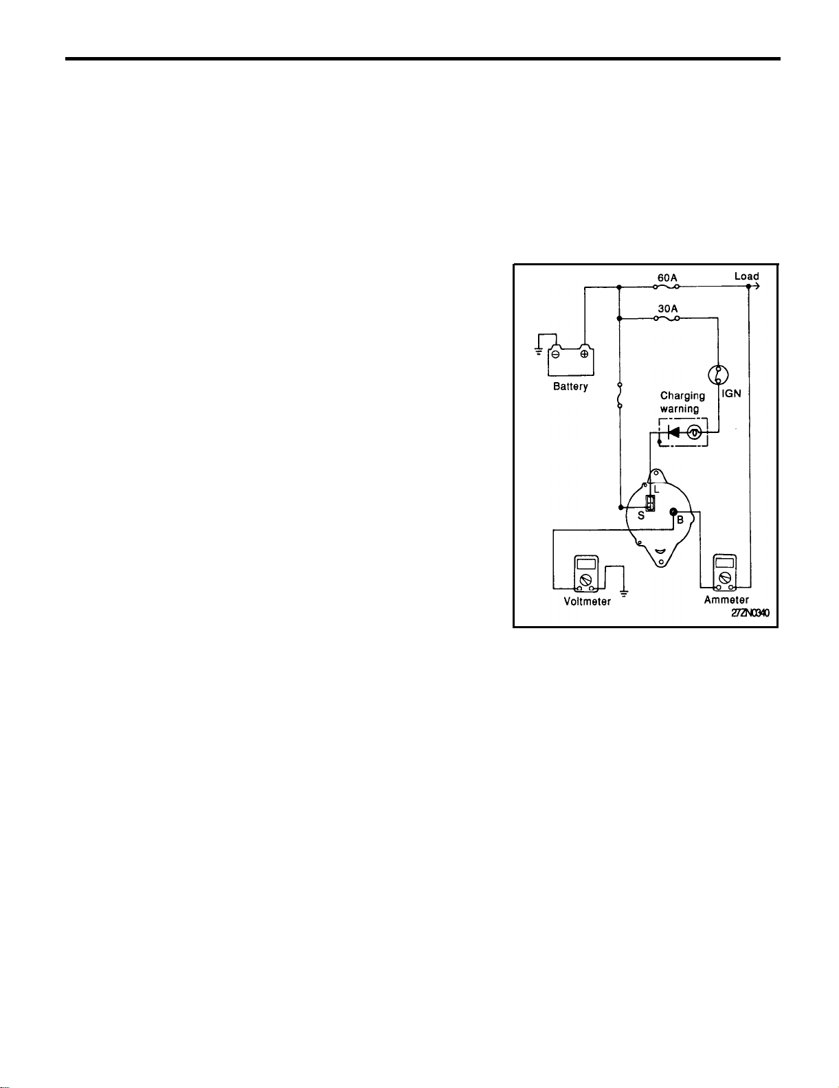
Connect a DC ammeter (0 to 100A) in series between the “B”
terminal and the disconnected output wire. Be sure to connect
the (-) lead wire of the ammeter to the disconnected output wire.
NOTE
Tighten each connection securely, as a heavy current will
flow. Do not rely on clips.
6.
Connect a voltmeter (0 to 20V) between the “B” terminal and
ground. Connect the (+) lead wire to the generator “B” terminal
and (-) lead wire to a good ground.
7.
Attach an engine tachometer and connect the battery ground
cable.
a.
Leave the engine hood open.
Page 16

27-16
CHARGING SYSTEM
Test
1.
Check to see that the voltmeter reads the same value as the
battery voltage.
If the voltmeter reads 0 V, and open circuit in the wire between
the generator "B" terminal and battery (-) terminal, a blown
fusible link or poor grounding is likey.
2.
Start the engine and turn on the headlights.
3.
Set the headlights to high beam and the heater blower switch
to HIGH, quickly increase the engine speed to 2,500 rpm and
read the maximum output current value indicated by the amme-
ter.
NOTE
After the engine start up, the charging current quickly
drops, therefore, the above operation must be done quickly
to read the maximum current value correctly.
Result
1.
The ammeter reading must be higher than the limit value. If it
is lower but the generator output wire is in good condition,
remove the generator from the vehicle and test it.
Limit value : 52.5A
NOTE
1)
The nominal output current value is shown on the
nameplate affixed to the generator body.
2)
The output current value changes with the electrical
load and the temperature of the generator itself.
Therefore, the nominal output current may not be
obtained. If such is the case, use a carbon pile to
increase the load on the generator.
The nominal output current may not be obtained if the
temperature of the generator itself or ambient temperature is too high.
2
Upon completion of the output current test, lower the engine
speed to idle and turn off the ignition switch.
3. Disconnect the battery ground cable.
4.
Remove the ammeter and voltmeter and the engine tachom-
eter.
5.
Connect the generator output wire to the generator “B” terminal.
6.
Connect the battery ground cable.
Page 17
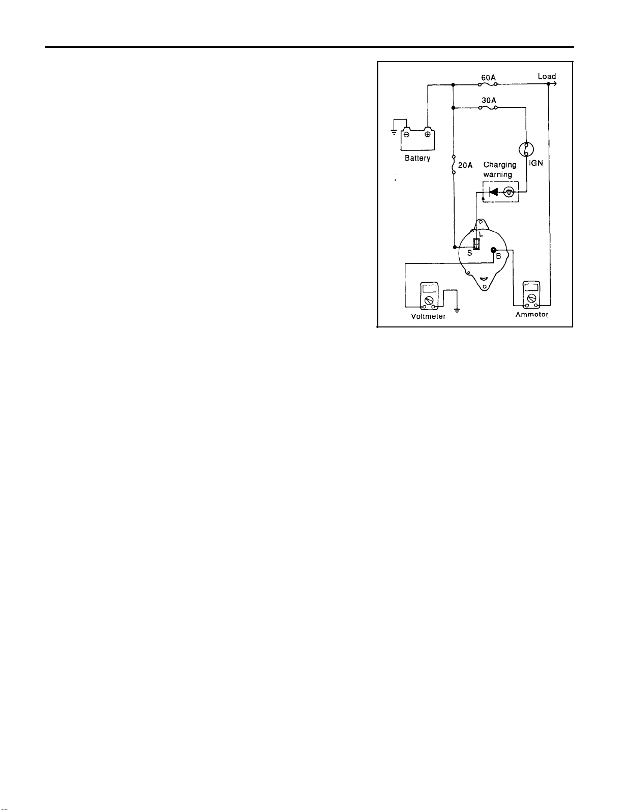
CHARGING SYSTEM
REGULATED VOLTAGE TEST
The purpose of this test is to check that the electronic voltage
regulator controls voltage correctly.
Preparation
1.
Prior to the test, check the following items and correct if
necessary.
1)
Check the battery installed on the vehicle to see that it is
fully charged. For battery checking method, see “BAT-
TERY”.
2)
Check the generator drive belt tension. For belt tension
check, see section, “COOLING”.
2. Turn ignition switch to “OFF”.
3.
Disconnect the battery ground cable.
4.
Connect a digital voltmeter between the “S” terminal of the
-generator and ground. Connect the (+) lead of the voltmeter to
the "S(L)" terminal of the generator. Connect the (-) lead to good
ground or the battery (-) terminal.
5.
Disconnect the generator output wire from the generator “B”
terminal.
6.
Connect a DC ammeter (0 to 100A) in series between the ”B”
terminal and the disconnected output wire. Connect the (-) lead
wire of the ammeter to the disconnected output wire.
7.
Attach the engine tachometer and connect the battery ground
cable.
27-17
Test
1.
Turn on the ignition switch and check to see that the voltmeter
indicates the following value.
Voltage: Battery voltage
If it reads 0 V, there is an open circuit in the wire between the
generator “S” terminal and the battery (+), or the fusible link is
blown.
2.
Start the engine. Keep all lights and accessories off.
3.
Run the engine at a speed of about 2,500 rpm and read the
voltmeter when the generator output current drops to 10 A or
less.
Page 18
27-18 CHARGING SYSTEM
Result
1.
If the voltmeter reading agrees with the value listed in the
Regulating Voltage Table below, the voltage regulator is func-
tioning correctly. If the reading is other than the standard value,
the voltage regulator or the generator is faulty.
Regulating Voltage Table
Voltage regulator ambient
temperature oC(oF)
Regulating voltage V
-20 (-4) 14.2-15.4
20 (68) 13.9-14.9
60 (140) 13.4-14.6
80 (176) 13.1-14.5
2. Upon completion of the test, reduce the engine speed to idle,
and turn off the ignition switch.
3.
Disconnect the battery ground cable.
4.
Remove the voltmeter and ammeter and the engine tachom-
eter.
5.
Connect the generator output wire to the generator "B" terminal.
6.
Connect the battery ground cable.
Page 19
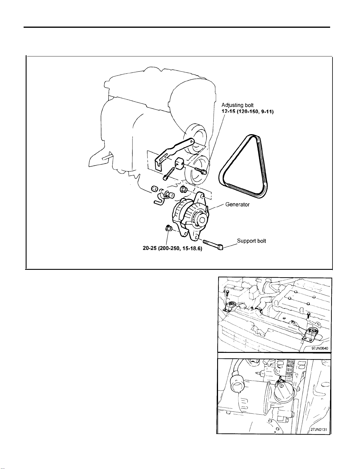
GENERRATOR
REMOVAL AND INSTALLATION
CHARGING SYSTEM
27-19
TORQUE : Nm (kg-cm, lb-ft)
1.
Disconnect the negative terminal from the battery.
2.
Remove the radiator mounting bolt.
3.
Disconnect the reservoir hose and fan motor connectors,
4. Raise the vehicle.
5.
Remove the mud guard-LH.
6. Disconnect the connector pin of oil pressure switch.
7.
Loosen the belt tension and remove the belt.
8.
Remove the terminal nut and the wire from the B terminal.
9.
With lifting up the radiator, remove the generator.
10. Installation is the reverse of the removal procedure.
Page 20
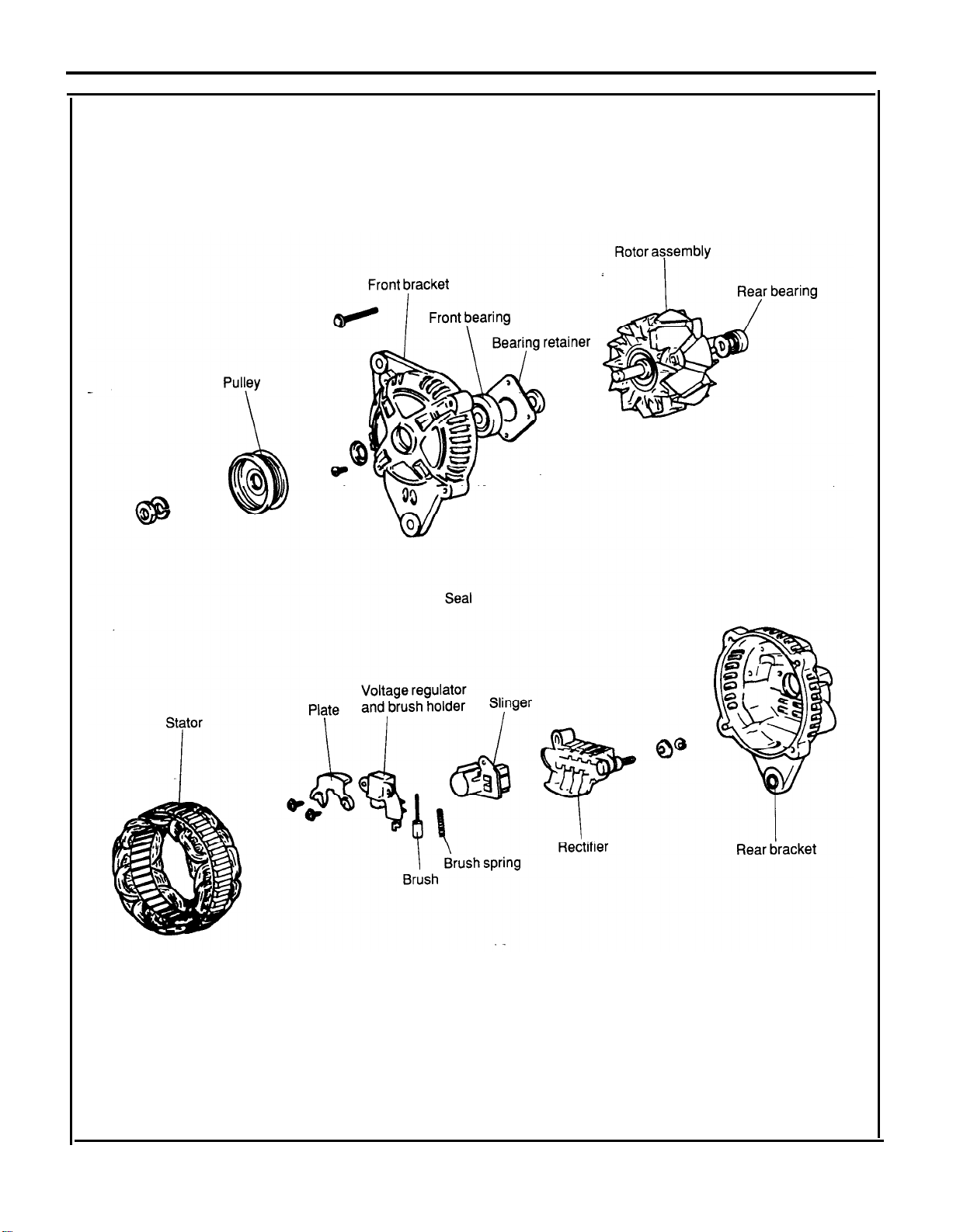
27-20
COMPONENTS
CHARGING SYSTEM
Page 21
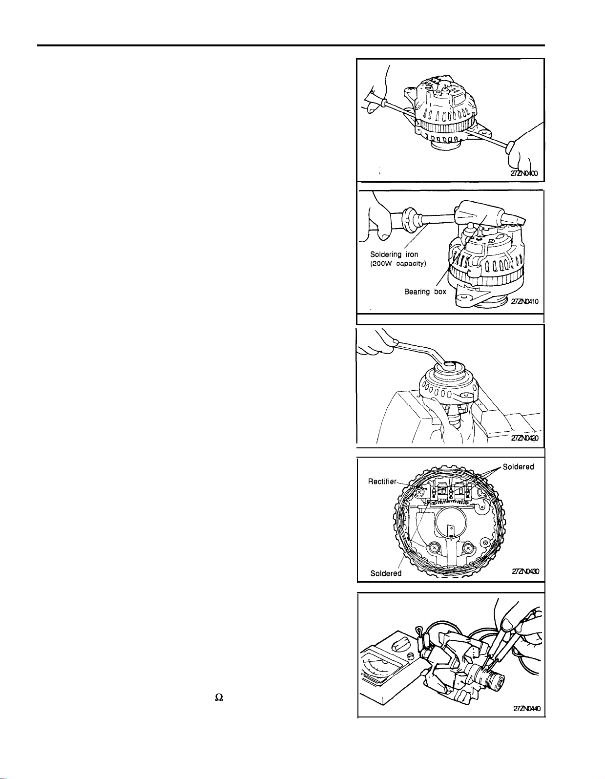
CHARGING SYSTEM
DISASSEMBLY
1.
Remove the three through bolts.
2.
Insert a flat screwdriver between the front bracket and stator
core, and pry downward.
NOTE
1)
Do not insert the screwdriver too deeply, as there is a
danger of damaging the stator coil.
2)
The rear cover may be hard to remove because a ring
is used to lock the outer race of the rear bearing. To
facilitate removal of rear cover, heat just the bearing
box section with a 200-watt soldering iron.
Do not use a heat gun, as it may damage the diode
assembly.
3.
Secure the rotor in a vise with the pulley side up.
NOTE
Be careful that the vise jaws do not damage the rotor.
27-21
4.
Remove the pulley nut, then remove the spring washer, then
the pulley, and then the spacer.
5.
Remove the front bracket and two seals.
6.
Remove the rotor from the vise.
7.
Remove the brush holder screws, the rectifier screws, and the
nut from the "B" terminal.
8.
Remove the stator assembly from the rear bracket.
9.
Detach the slinger from the brush holder.
10. When the stator is to be removed, unsolder the three stator
leads to the main diodes on the rectifier.
NOTE
1)
When soldering or unsoldering, use care to make sure
that heat of soldering iron is not transmitted to the
diodes for a long period.
2)
Use care that excessive force is not exerted on the
leads of the diodes.
11. When separating the rectifier from the brush holder, unsolder
the two plates soldered to the rectifier.
INSPECTION
Rotor
1.
Check the rotor coil for continuity. Check to make sure that
there is continuity between the slip rings.
If resistance is extremely low, it means that there is a short. If
there is no continuity or if there is a short circuit, replace the rotor
assembly.
Resistance value: Approx. 3.1
Page 22
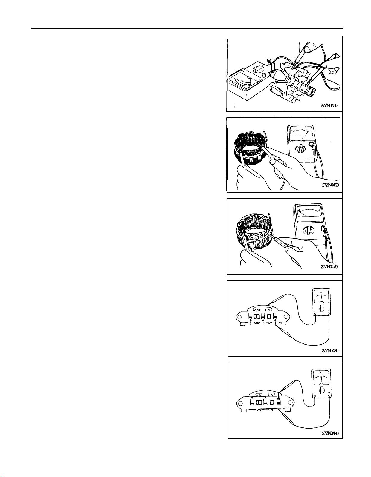
27-22 CHARGING SYSTEM
Check the rotor coil for a ground. Check to make sure that there
2.
is no continuity between slip the ring and the core.
If there is continuity, replace rotor assembly.
Stator
Make a continuity check on the stator coil. Check to make sure
1.
that there is continuity between the coil leads.
If there is no continuity, replace stator assembly.
Check the coil for grounding. Check to make sure that there is
2.
no continuity between the coil and the core.
If there is continuity, replace the stator assembly.
Rectifiers
Positive rectifier test
Check for continuity between the positive rectifier and stator coil
lead connection terminal with an ohmmeter. The ohmmeter should
read continuity in only one direction. If there is continuity in both
directions, a diode is shorted.
Replace the rectifier assembly.
Negative rectifier test
Check for continuity between the negative rectifier and the stator
coil lead connection terminal. The ohmmeter should read continuity
in only one direction. If there is continuity in both directions, a diode
is shorted, and the rectifier assembly must be replaced.
Page 23
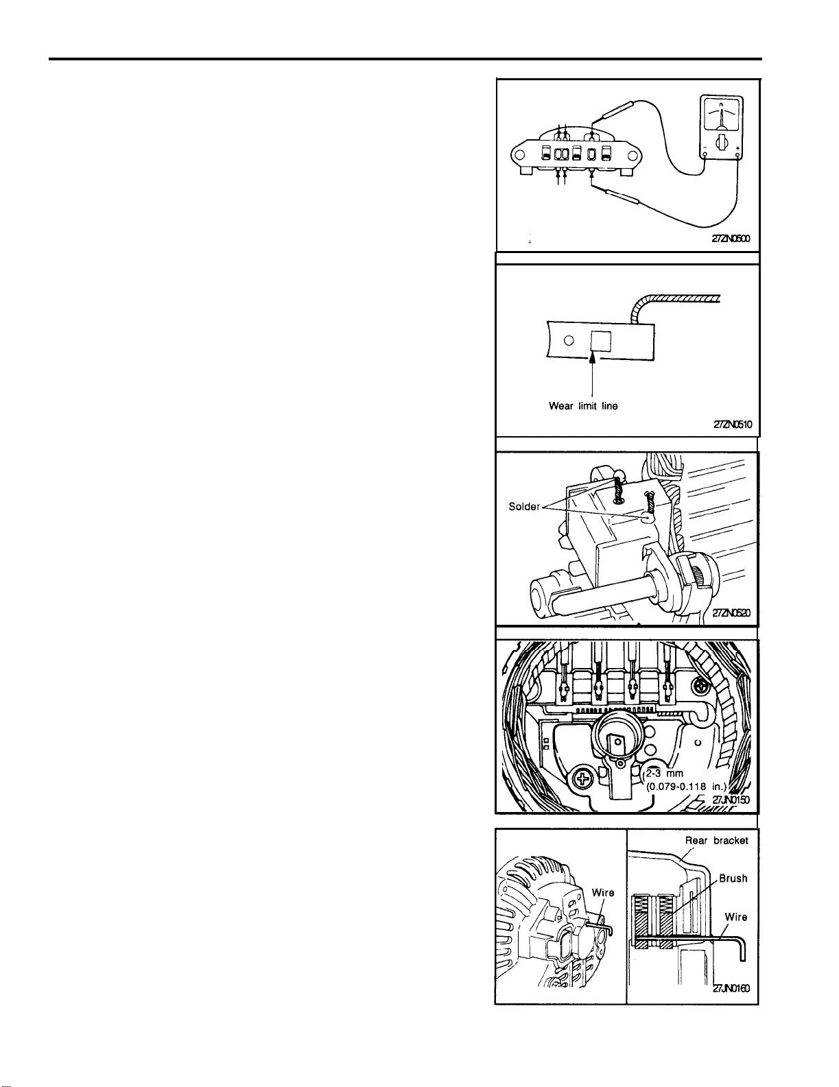
CHARGING SYSTEM
Diode trio test
Check the three diodes for continuity by connecting an ohmmeter
to both ends of each diode. Each diode should have continuity in
only one direction.
If continuity is present in both directions, a diode is defective and the
heatsink assembly must be replaced.
BRUSH REPLACEMENT
Replace the brushes if they are worn to limit line.
27-23
1.
Unsolder the pigtail and remove the old brush and spring.
2.
Install the brush spring and a new brush in the brush holder.
3.
Insert the brush to where there is a space 2 to 3 mm (0.079 to
0.118 in.) between the limit line and the end of the brush holder.
4.
Solder the pigtail to the brush holder.
REASSEMBLY
Perform reassembly in the reverse procedure of disassembly. Pay
attention to the following:
Before the rotor is attached to the rear bracket, insert a wire through
the small hole in the rear bracket to lock the brush. After the rotor
has been installed, the wire can be removed.
Page 24
27-24
CHARGING SYSTEM
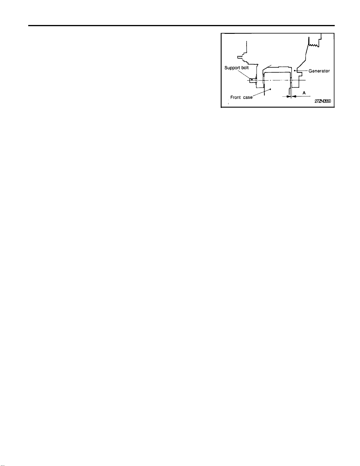
INSTALLATION
1.
Position the generator and insert the support bolt. (Do not
attach the nut.)
2.
Push the generator forward and determine how many spacers
(thickness: 0.198 mm) should be inserted between the front leg
of the generator and the front case (space A in the illustration).
(There should be enough spacers so that they do not fall out
when you let go of them.)
3.
Insert the spacers (space A in the illustration), attach the nut,
and complete the installation.
Page 25
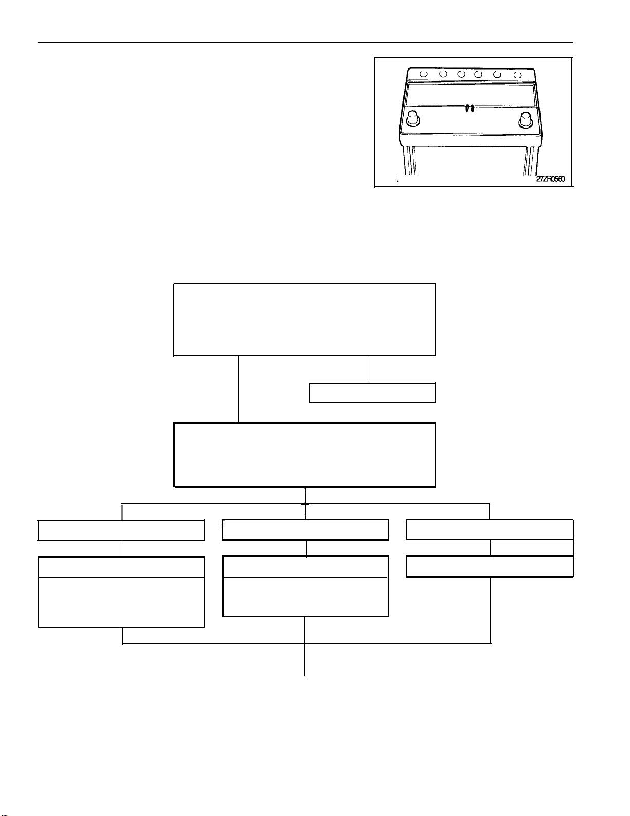
CHARGING SYSTEM
BATTERY
The maintenance-free battery is, as the name implies, totally
1.
maintenance free and has no removable battery cell caps.
Water never needs to be added to the maintenance-free
2.
battery.
The battery is completely sealed, except for small vent holes in
3.
the cover.
BATTERY VISUAL INSPECTION (1)
Check for obvious damage such as a cracked or broken
case or cover that could permit loss of electrolyte.
Determine cause of damage and correct as needed.
Clean corrosion with as solution of baking soda and
water.
27-25
Check specific gravity.
Refer to “Specific gravity check chart” for electrolyte
temperature compensation, and then select proper
reading below.
Below 1.100
Slow charge
Slow charge battery at 5A for no
more than 14 hrs., then perform
load test.
Not O.K.
Replace battery
O.K.
1.100 - 1.220
Recharge
Refer to charging guide and safety
precautions
Above 1.220
Perform load test
To be Continued
Page 26
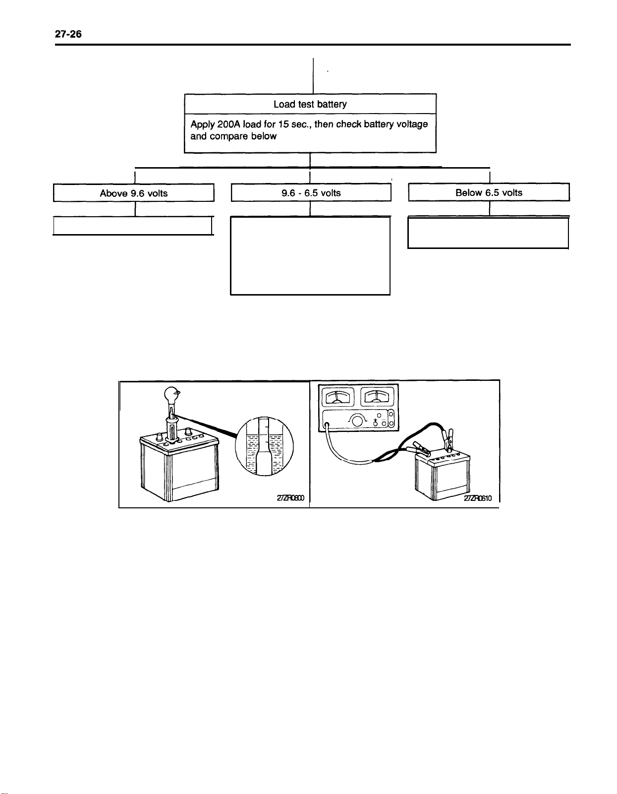
CHARGING SYSTEM
Battery O.K./Reuse
Fast charge battery and then per-
form load test again.
NOTE: If battery is still less than
9.6 volts after second fast charge
and load test, then it should be
replaced
Battery no good.
Replace
Page 27
CHARGING SYSTEM
27-27
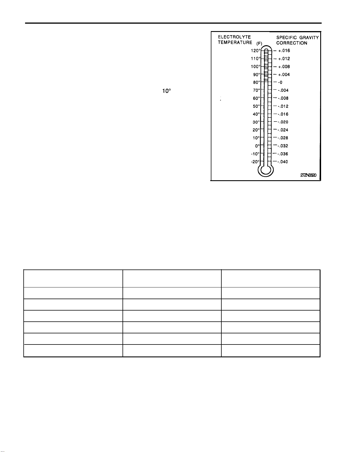
SPECIFIC GRAVITY CHECK CHART
The specific gravity of battery electrolyte changes with temperature. Heat thins the solution and lowers the specific gravity. Cold
thickens the solution and raises the specific gravity.
A fully charged battery should have a specific gravity between
1.260 and 1.280, with the electrolyte temperature at 80§F, the
specific gravity reading must be corrected by adding 4 points (.004)
for each 10o above 80°F or subtracting 4 points for every
80°F.
For example : The hydrometer reading is 1.280, and the electrolyte
temperature reading is 10°F. By using the chart, the specific gravity
must be lowered by 0.028 points. The true corrected reading is
1.252.
1.280 - 0.028 = 1.252
You should never take a hydrometer reading immediately after
water has been added. The water and electrolyte must be mixed by
either charging for a few minutes at a low rate or by allowing the
battery to sit for an hour.
NOTE
A difference of 50 points (0.050) or more between one or more
ceils indicates a defective battery. It should be replaced.
10o
below
BATTERY CHARGE RATE
Charge method
Specific gravity
Below 1.100
1.100 - 1.130
1.130 - 1.160
1.160 - 1.190
1.190 Above
1.220
1.220
Slow charge (5A)
14 hours
12 hours
10 hours
8 hours
6
hours
4
hours
Fast charge (20A)
4 hours
3 hours
2.5 hours
2.0 hours
1.5
hours
1.0
hours
Page 28
27-28 CHARGING SYSTEM
BATTERY VISUAL INSPECTION (2)
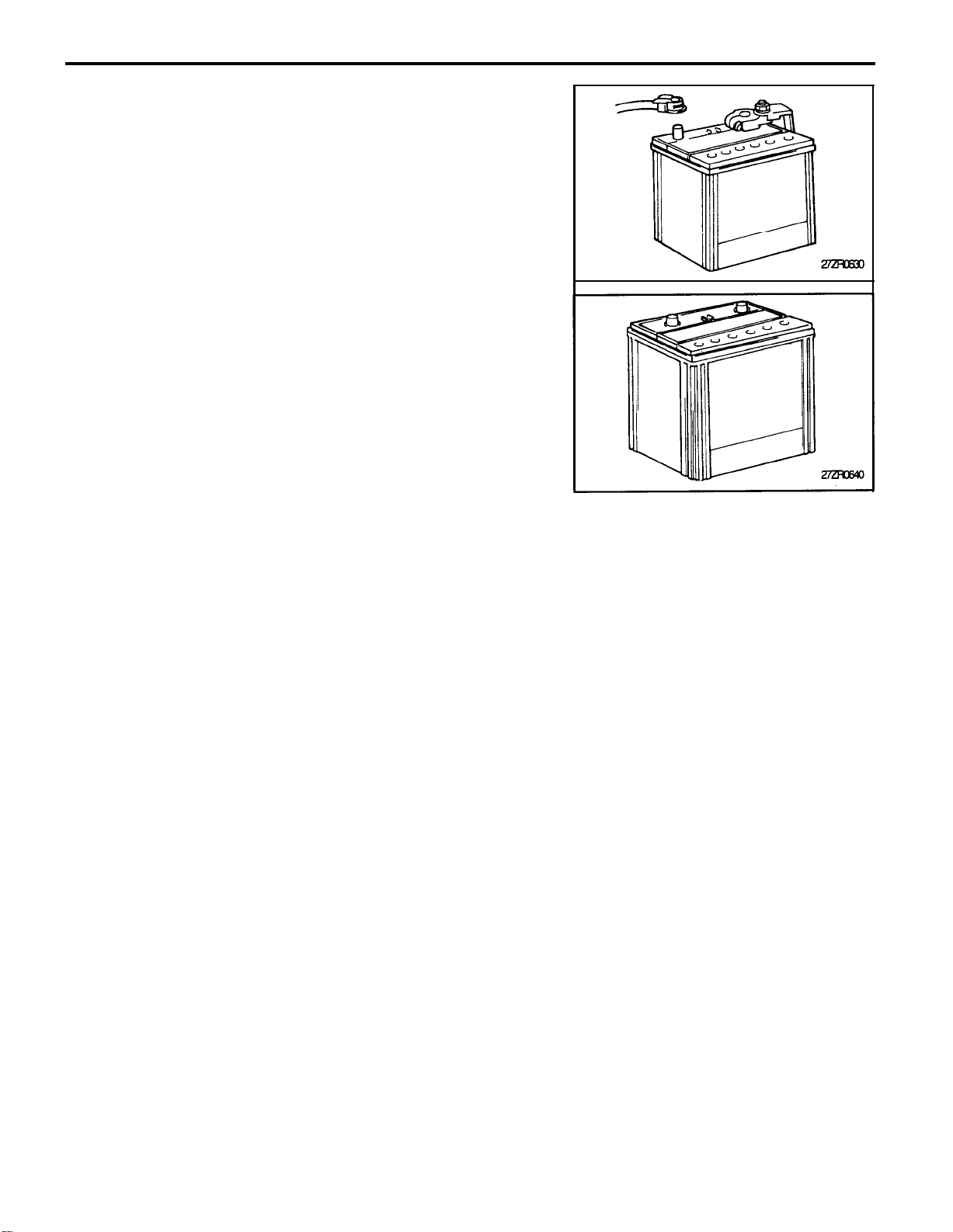
1.
Make sure ignition switch is in the Off position and all accessories are Off.
2.
Disconnect the battery cables (negative first)
3.
Remove the battery from the vehicle.
CAUTION
Care should be taken in the event the battery case is
cracked or leaking, to protect your skin from the electrolyte. A suitable pair of rubber gloves (not household type)
should be worn when removing the battery.
4.
Inspect the battery carrier for damage caused by the loss of acid
from the battery. If acid damage is present, it will be necessary
to clean the area with a solution of clean warm, water and
baking soda. Scrub the area with a stiff bristle brush and wipe
off with a cloth moistened with baking soda and water.
5. Clean the top of the battery with the same solution as described
in Step (4).
6.
Inspect the battery case, and cover, for cracks. If cracks are
present, the battery must be replaced.
7.
Clean the battery posts with a suitable battery post cleaner.
8.
Clean the inside surface of the terminal clamps with a suitable
battery terminal cleaning tool. Replace damaged or frayed
cables and broken terminal clamps.
9.
Install the battery in the vehicle.
10. Connect the cable terminals to the battery post, making sure
the top of the terminals are flush with the top of the post.
11. Tighten the terminal nut securely.
12. Coat all connections with light mineral grease after tightening.
CAUTION
When batteries are being charged, an explosive gas forms
beneath the cover of each cell. Do not smoke near batteries
being charged or which have recently been charged.
Do not break live circuits at the terminals of the batteries
being charged. A spark will occur where the circuit is
broken.
Keep all open flames away from the battery.
Page 29
STARTING SYSTEM
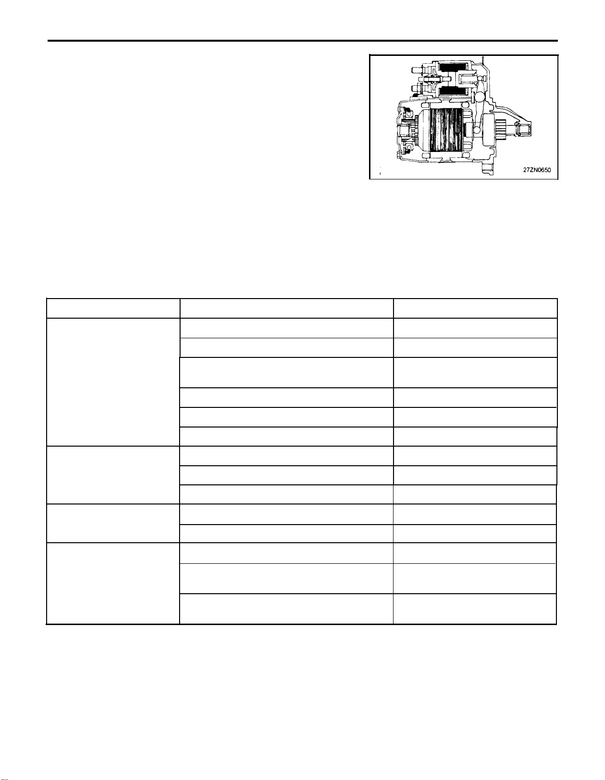
GENERAL INFORMATION
The starting system includes the battery, start motor, solenoid
switch, ignition switch, transaxle range switch (A/T only), connection wires, and the battery cables.
When the ignition key is turned to the start position, current flows
and energizes the coil of the start motor’s solenoid. When this
happens, the solenoid plunger and the clutch shift lever are
activated, and the clutch pinion engages the ring gear. The
contacts close and the start motor cranks.
In order to prevent damage caused by excessive rotation of the
starter armature when the engine starts, the clutch pinion gear
overruns.
TROUBLESHOOTING
27-29
Trouble condition
Engine will not crank.
Engine cranks slowly.
Starter keeps running.
Starter spins but engine
will not crank.
Probable cause
Battery charge low
Battery cables loose, corroded or worn
Transaxle range switch faulty
(Vehicle with automatic transaxle only)
Fusible link blown Replace fusible link.
Starter motor faulty Repair start motor.
Ignition switch faulty
Battery charge low
Battery cables loose, corroded or worn
Starter motor faulty
Starter motor faulty
lgnition switch faulty Replace ignition switch.
Short in wiring
Pinion gear teeth broken or starter
motor faulty
Remedy
Charge or replace battery.
Repair or replace cables,
Adjust or replace switch.
Replace ignition switch.
Charge or replace battery.
Repair or replace cables.
Repair start motor.
Repair start motor.
Repair wiring.
Repair start motor.
Ring gear teeth broken
Replace flywheel ring gear or
torque converter.
Page 30
27-30
STARTING SYSTEM
SERVICE ADJUSTMENT PROCEDURES
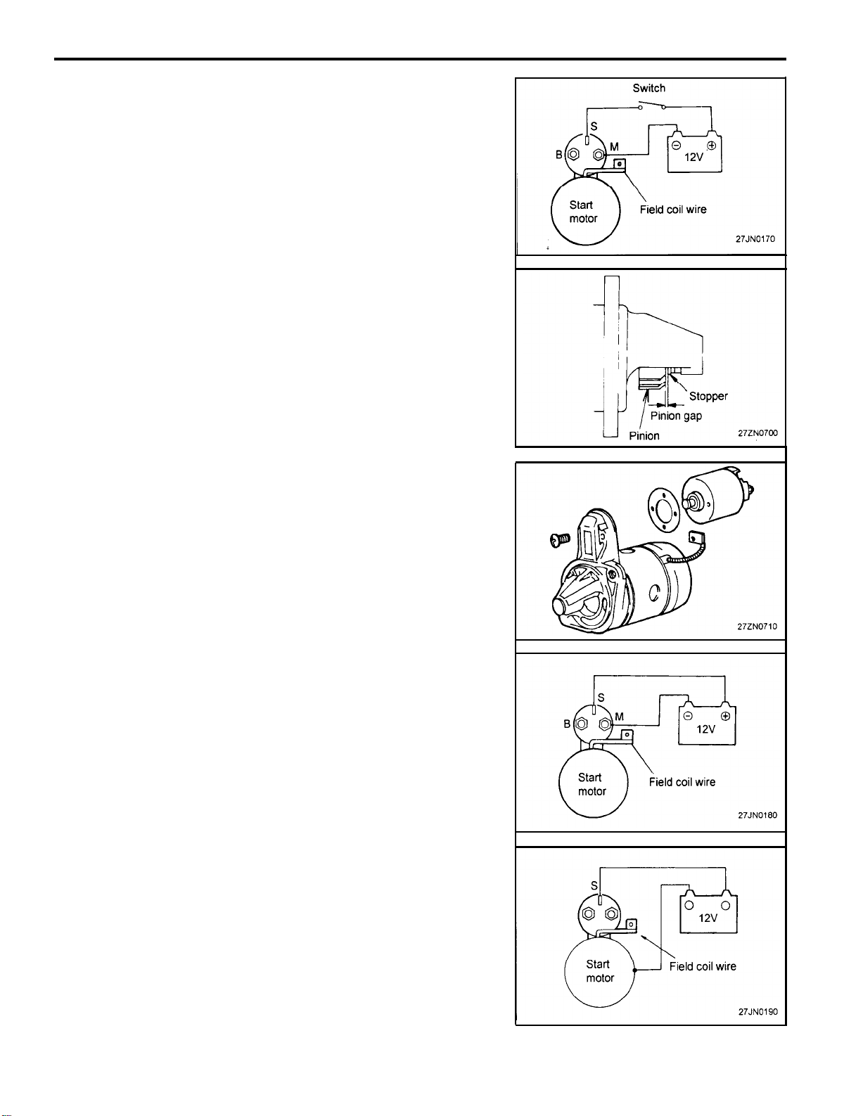
PINION GAP ADJUSTMENT
1.
Disconnect the field coil wire from the M-terminal of the solenoid.
2.
Connect a 12V battery the S-terminal and the M-terminal.
3.
The pinion will move out.
NOTE
This test must be performed quickly (in less than 10
seconds) to prevent the coil from burning.
4.
Check the pinion to stopper clearance (pinion gap) with a feeler
gauge.
Pinion gap : 052.0 mm (0.02-0.079 in.)
5.
If the pinion gap is out of specifcation, adjust by adding or
removing gaskets between the solenoid and the front bracket.
MAGNETIC SWITCH PULL-IN TEST
1.
Disconnect the field coil wire from the M-terminal of the magnetic switch.
2.
Connect a 12V battery between the S-terminal and the Mterminal.
NOTE
This test must be performed quickly (in less than 10
seconds) to prevent the coil from burning.
3.
If the pinion moves out, then the pull-in coil is good. If it doesn’t,
replace the magnetic switch.
MAGNETIC SWITCH HOLD-IN TEST
1.
Disconnect the field coil wire from the M-terminal of the magnetic switch.
2.
Connect a 12V battery between the S-terminal and the body.
NOTE
This test must be performed quickly (in less than 10
seconds) to prevent the coil from burning.
3.
If the pinion moves out, everything is in order. If the pinion
moves, the hold-in circuit is open. Replace the magnetics witch.
Page 31
STARTING SYSTEM
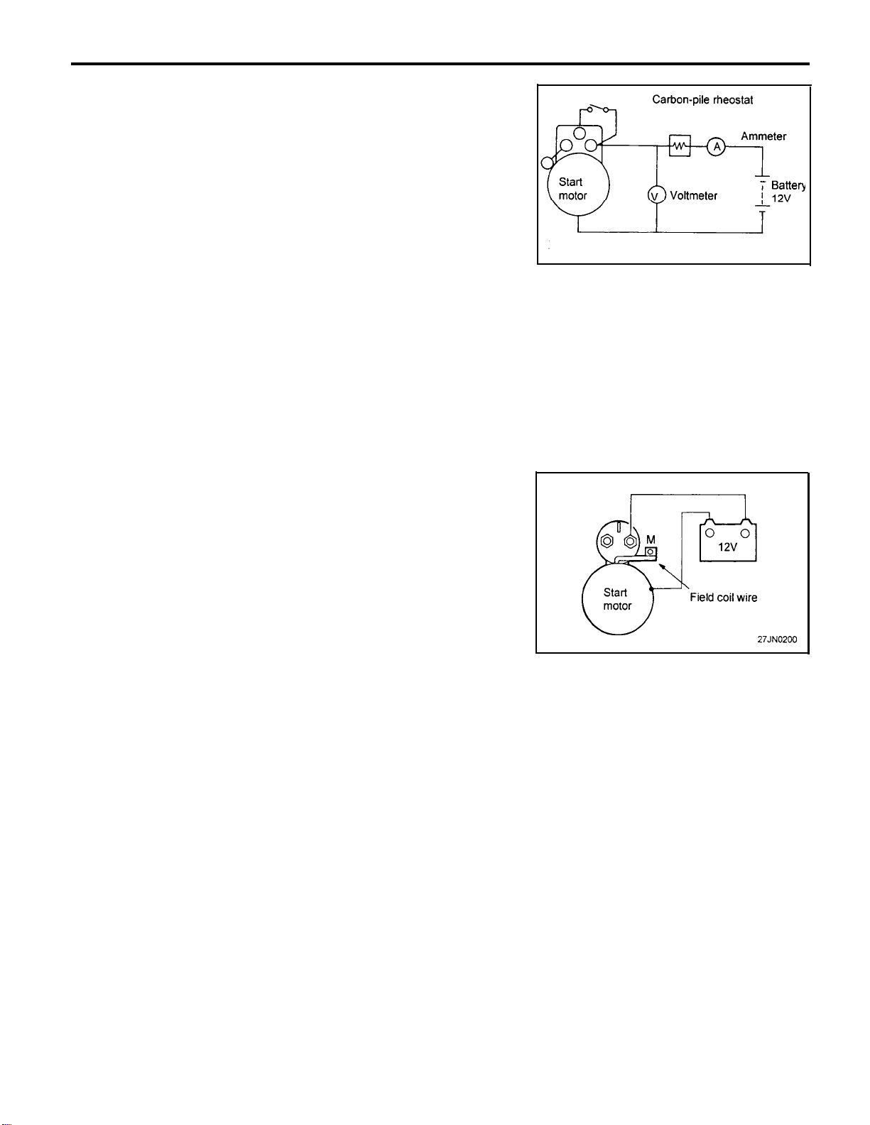
FREE RUNNING TEST
1.
Place the start motor in a vise equipped with soft jaws and
connect a fully-charged 12-volt battery to start motor as
follows:
2.
Connect a test ammeter (100-ampere scale) and carbon pile
rheostat as shown is the illustration.
3.
Connect a voltmeter (15-volt scale) across start motor.
4.
Rotate carbon pile to the off position.
5.
Connect battery cable from battery negative post to start motor
body.
6.
Adjust until battery voltage shown on the voltmeter reads 11
volts.
7.
Confirm that the maximum amperage is within the specifications and that the start motor turns smoothly and freely.
Current: Max. 90 Amps
Speed: Min. 3,000 rpm
27-31
MAGNETIC SWITCH RETURN TEST
1.
Disconnect field coil wire from the M-terminal of the magnetic
switch.
2.
Connect a 12V battery between M-terminal and the body.
NOTE
This test must be performed quickly (in less than 10
seconds) to prevent the coil from burning.
3.
Pull pinion out and release. If pinion returns quickly to its original
position, everything is in order. If it doesn’t, replace the magnetic switch.
Page 32
27-32
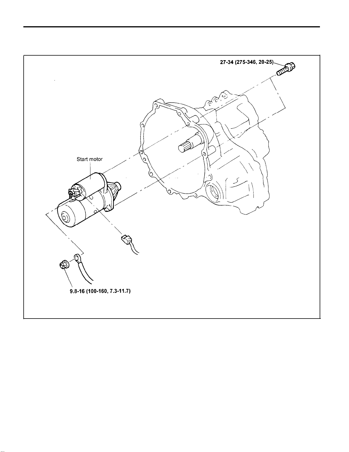
START MOTOR
REMOVAL AND INSTALLATION
STARTING SYSTEM
TORQUE : Nm (kg-cm, Ib.ft)
Page 33
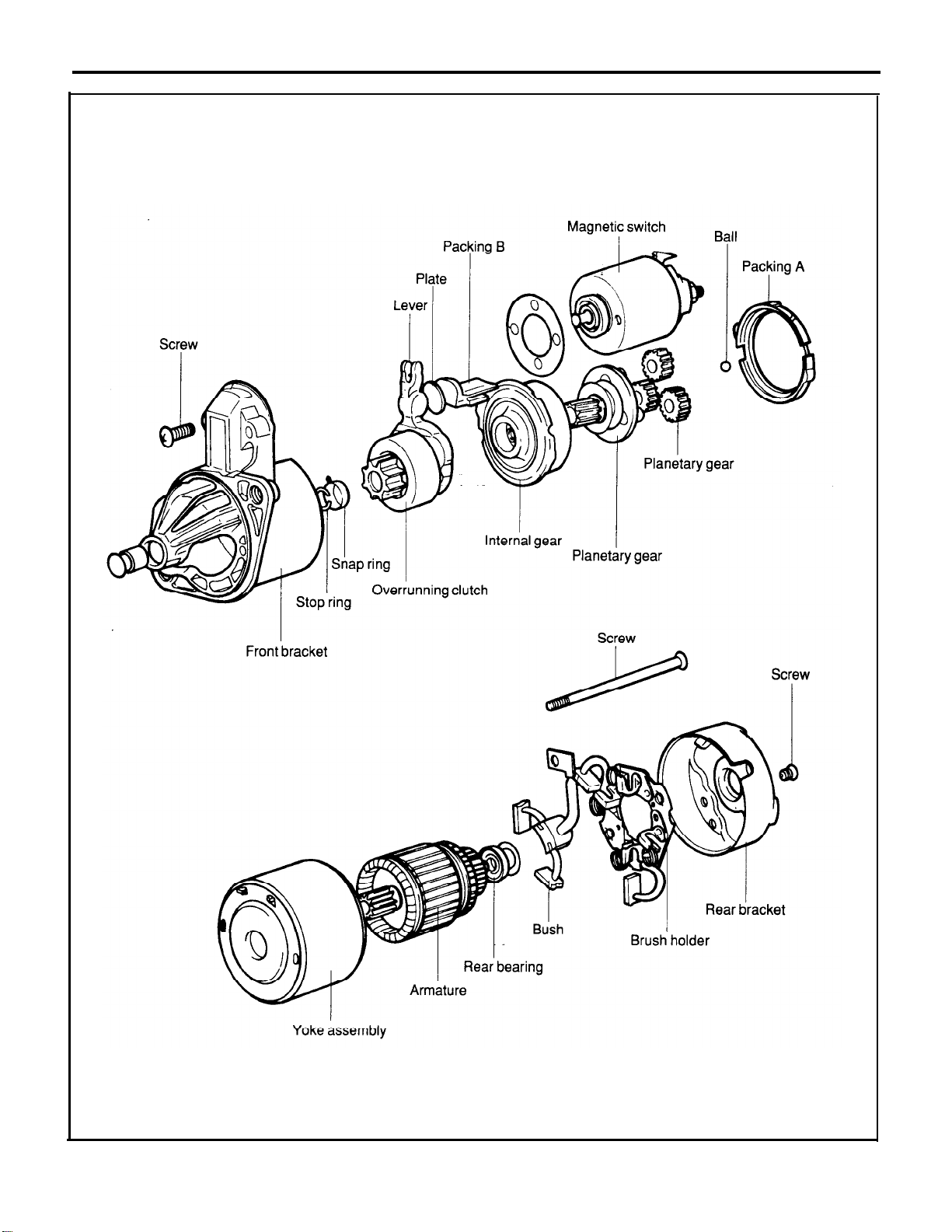
COMPONENTS
STARTING SYSTEM
27-33
Page 34
27-34
STARTING SYSTEM
DISASSEMBLY
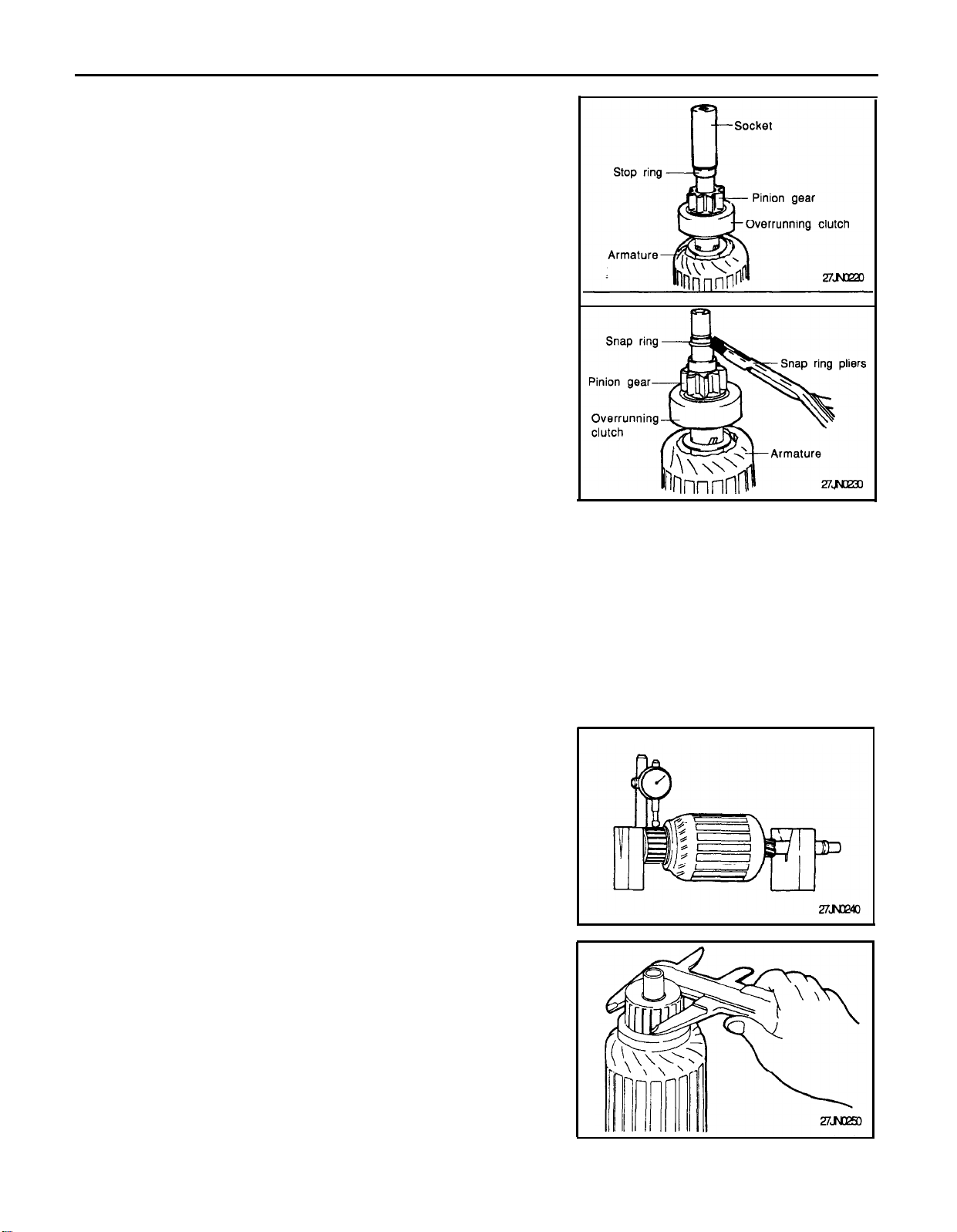
REMOVAL OF SNAP RING AND STOP RING
1.
Press the stop ring, by using an appropriate socket wrench, to
the snap ring side.
2.
After removing the snap ring (by using snap-ring pliers), re-
move the stop ring and the overrunning clutch.
CLEANING STARTER MOTOR PARTS
1.
Do not immerse parts in cleaning solvent. Immersing the yoke
and field coil assembly and/or armature will damage insulation.
Wipe these parts with a cloth only.
2.
Do not immerse drive unit in cleaning solvent. Overrunning
clutch is pre-lubricated at the factory and solvent will wash
lubrication from clutch.
3.
The drive unit may be cleaned with a brush moistened with
cleaning solvent and wiped dry with a cloth.
INSPECTION
CHECKING THE COMMUTATOR
1.
Place the armature on a pair of V-blocks, and check the
deflection by using a dial gage.
Standard value: 0.05 mm (0.002 in.)
Limit: 0.1 mm (0.0039 in.)
2.
Check the outer diameter of the commutator.
Standard value: 29.4 mm (1.157 in.)
Limit: 28.4 mm (1.118 in.)
Page 35
STARTING SYSTEM 27-35
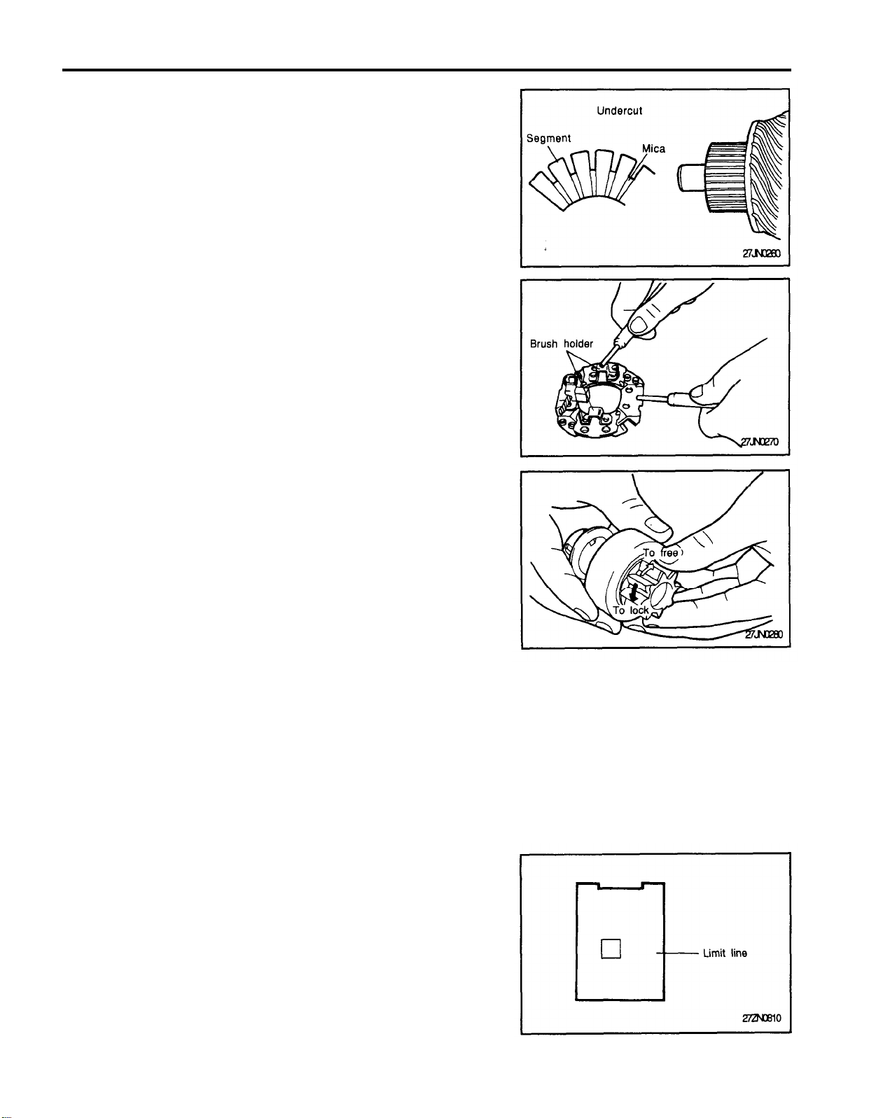
3. Check the depth of the undercut between segments.
Standard value: 0.5 mm (0.020 in.)
Limit: 0.2 mm (0.0079 in.)
BRUSH HOLDER
Check for continuity between the brush holder plate and the brush
holder.
The normal condition is no continuity.
OVERRUNNING CLUTCH
1.
While holding clutch housing, rotate the pinion. Drive pinion
should rotate smoothly in one direction, but should not rotate in
opposite direction. If clutch does not function properly, replace
overrunning clutch assembly.
2.
Inspect pinion for wear or burrs. If pinion is worn or burred,
replace overrunning clutch assembly. If pinion is damaged,
also inspect ring gear for wear or burrs.
FRONT AND REAR BRACKET BUSHING
Inspect bushing for wear or burrs. If bushing is worn or burred,
replace front bracket assembly or rear bracket assembly.
REPLACEMENT OF BRUSHES AND SPRINGS
1.
Brushes that are worn beyond wear limit line, or oil-soaked,
should be replaced.
2.
When replacing field coil brushes, crush worn brush with pliers,
taking care not to damage pigtail.
Page 36
27-36
3.
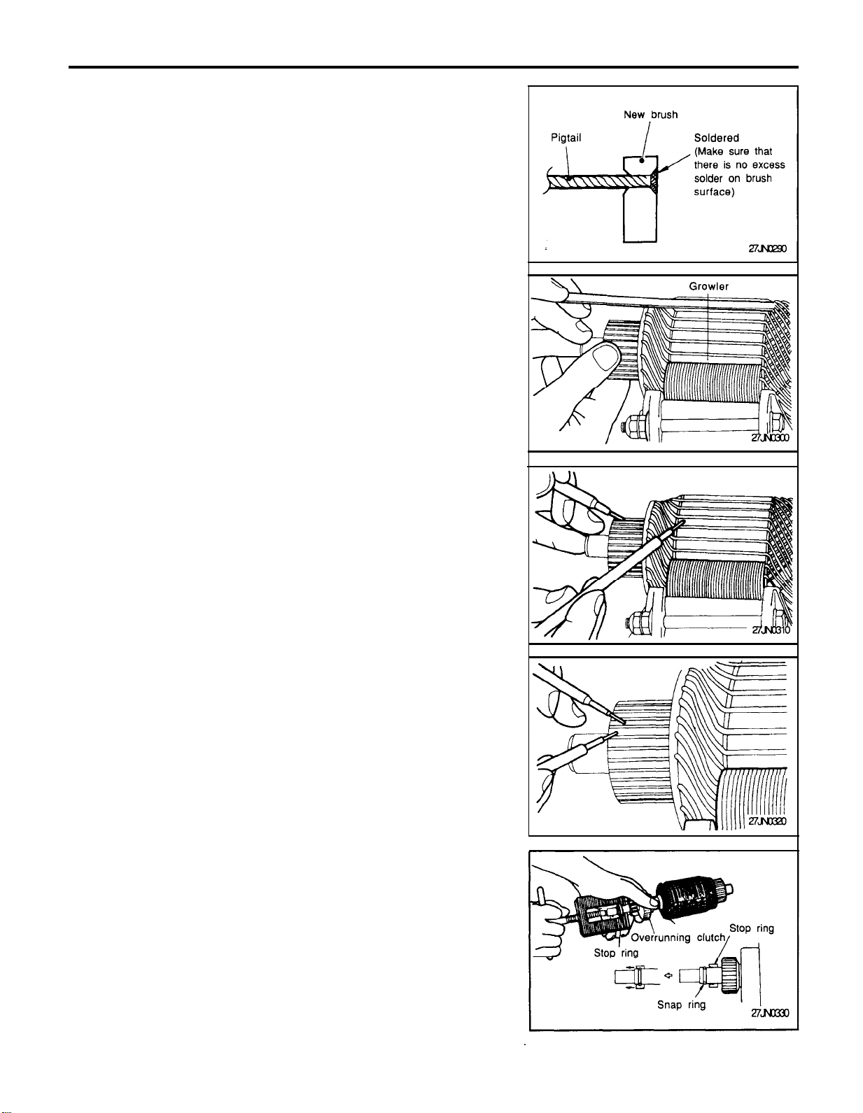
Sand pigtail end with sandpaper to ensure good soldering..
4.
Insert pigtail into hole provided in new brush and solder it. Make
sure that pigtail and excess solder do not come out onto brush
surface.
5.
When replacing ground brush, slide the brush from brush
holder by prying retaining spring back.
STARTING SYSTEM
TESTING ARMATURE
TESTING ARMATURE FOR SHORT-CIRCUIT
1. Place armature in a growler.
2, Hold a thin steel blade parallel and just above while rotating
armature slowly in growler. A shorted armature will cause bladeto vibrate and be attracted to the core. Replace shorted
armature.
TESTING ARMATURE FOR GROUNDING
Check the insulation between the armature coil cores and the
commutator segments. They are normal if there is no continuity.
CHECKING FOR ARMATURE COIL WIRING
DAMAGE/DISCONNECTION
Check for continuity between segments. The condition is normal if
there is continuity.
SERVICE POINTS OF ASSEMBLY
INSTALLATION OF THE STOP RING AND SNAP
RING
Using a suitable pulling tool, pull overrunning clutch stop ring over
snap ring.
Page 37
STARTING SYSTEM
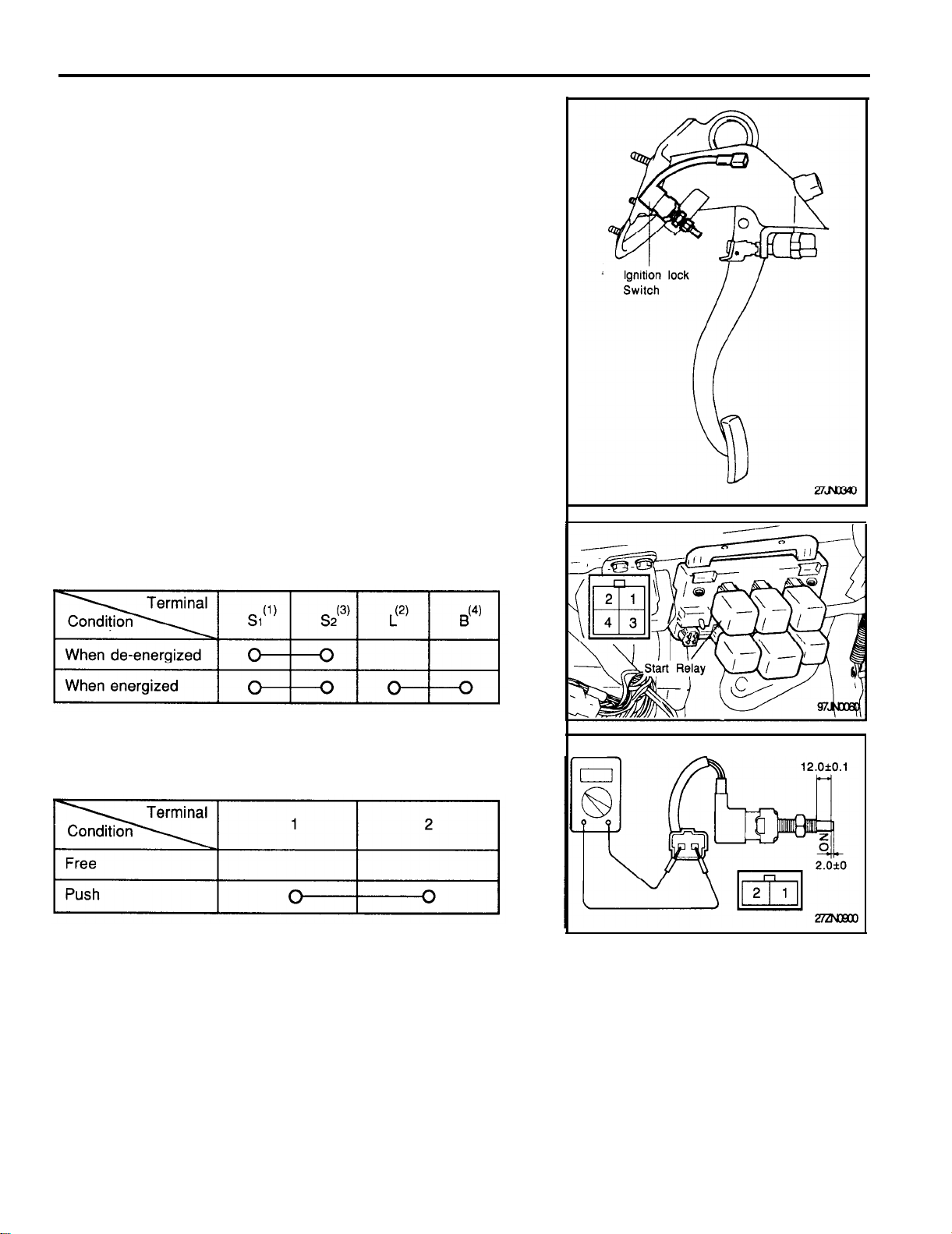
INSPECTION OF CLUTCH START SYSTEM
(IGNITION LOCK SYSTEM)
Check clutch pedal
Check that pedal height, pedal freeplay and clutch pedal clevis pin
play are correct. (Refer to clutch group)
27-37
Check starter relay
Remove the starter relay and check continuity between the terminals. If the continuity is not as specified, replace the relay.
Check ignition lock switch
Remove the ignition lock switch and check continuity between
terminals. If the continuity is not as specified, replace the switch.
Page 38
27-38
CRUISE CONTROL
SPECIFICATIONS
CRUISE CONTROL
Items
Speed control module
Operating voltage range
Operating temperature
Voltage drop between module and actuator
Operating speed range
Vacuum pump
Type
Actuator
Drive system
Stroke mm (in.)
Cruise main switch
Rated voltage
Operating force
Voltage drop
Stop lamp switch
Rated voltage
Rated load
Stop lamp
Specifications
DC 10 ~ 16 V
-30 ~ + 100oC (-22 ~ + 167oF)
0.4 V
Low speed limit : 40 ± 3 km/h (25 ± 2 mph)
High speed limit : 160 ± 5 km/h (90 ± 3 mph)
Diaphragm type
Vacuum type
36-42 (1.5-1.7)
DC12V
0.3 ~ 1.0 kg
0.15 V or less
DC 12 V
21 x 5 W (lamp load)
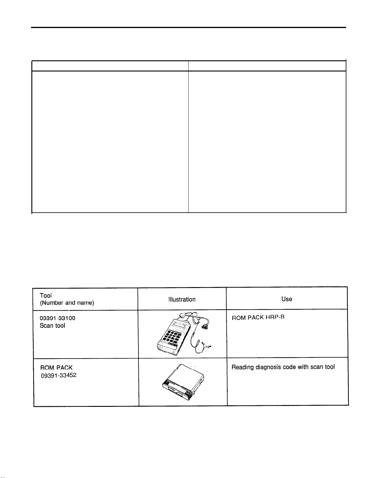
SPECIAL SERVICE TOOL
Page 39
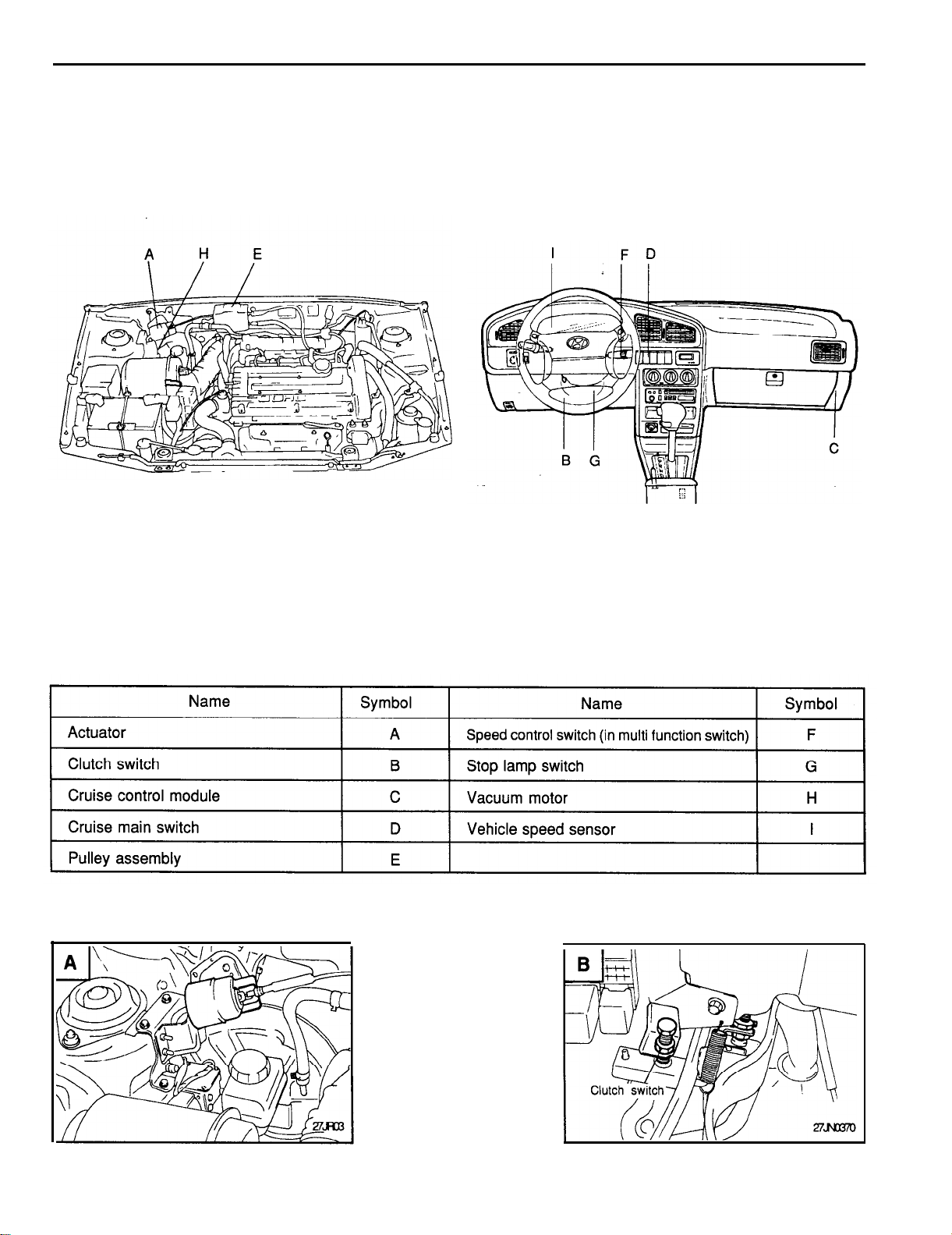
COMPONENTS LOCATION
CRUISE CONTROL
27-39
Engine compartment
Interior
Page 40
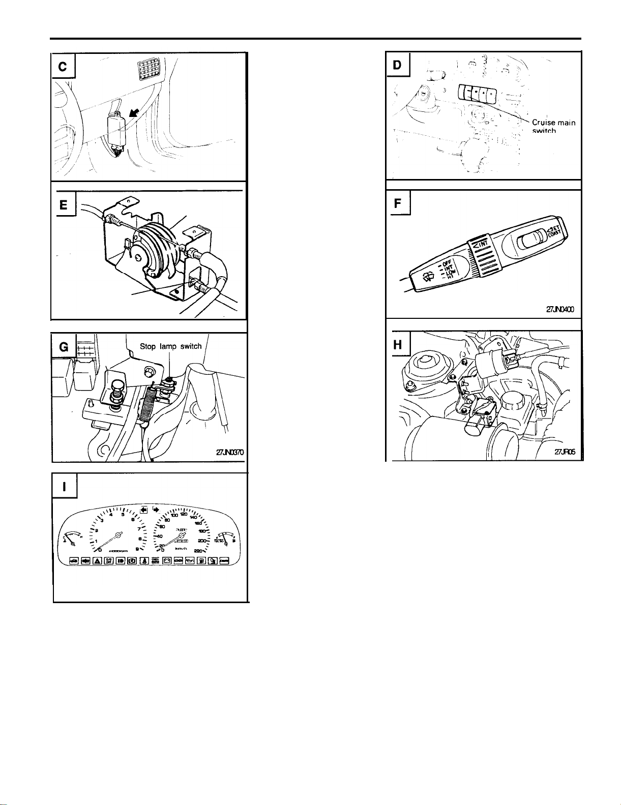
27-40
CRUISE CONTROL
Page 41
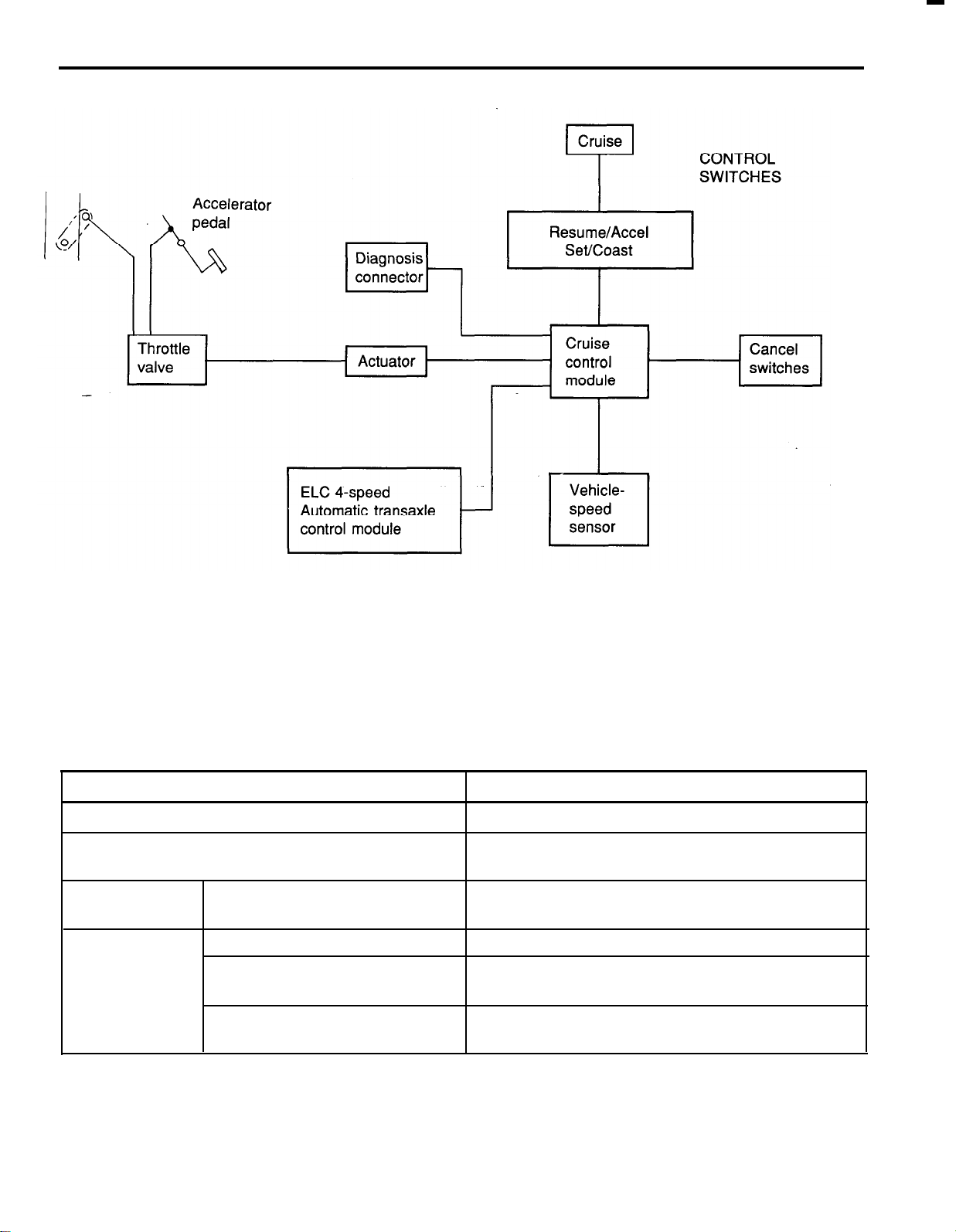
System Block Diagram
CRUISE CONTROL
27-41
Component parts and function outline
COMPONENT PART
Vehicle-speed sensor
Cruise control module (CCM)
Actuator
CRUISE main switch
Control switch
SET switch
RESUME switch
CRUISE main switch indicator
* CCM : Cruise Control Module
FUNCTION
Converts vehicle speed to pulse.
Receives signals from sensor and control switches;
CCM controls all automatic speed control functions.
Regulates the throttle valve to the set opening by signal
from the CCM.
Switch for automatic speed control power supply.
Controls automatic speed control functions by SET
(COAST) and RESUME (ACCEL).
Illuminates when CRUISE main switch is ON (Built into
cluster).
Page 42
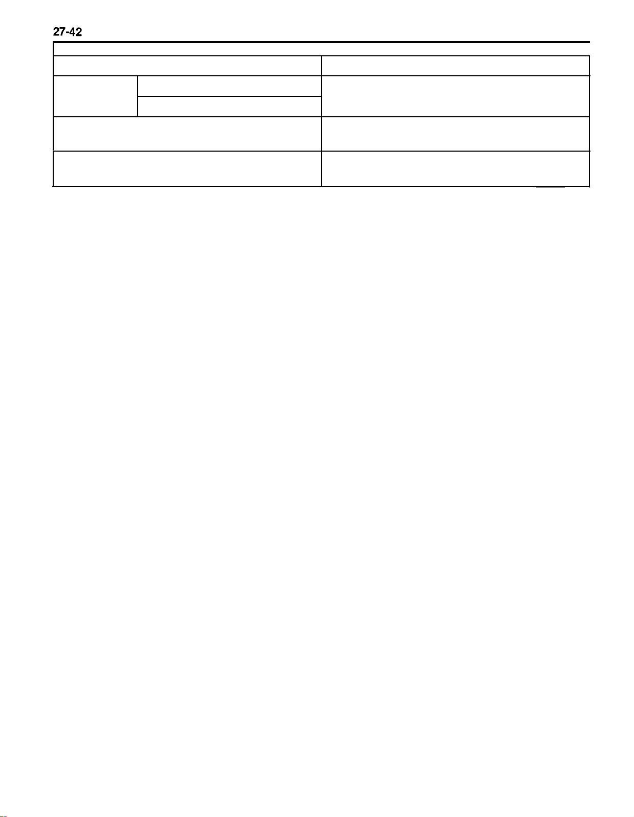
CRUISE CONTROL
FUNCTION
Cancel switch
COMPONENT PART
Stop lamp switch/Clutch switch (M/T)
Sends cancel signals to the CCM.
Inhibitor switch
ELC 4-speed automatic transaxle control module
Controls the overdrive ON and OFF, based on signals
from the CCM for the CC.
Data link connector By connecting the check light or scan tool, control unit
diagnostic codes can be read.
* CC : Cruise Control
Page 43
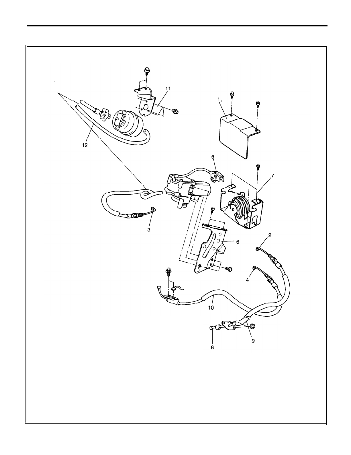
REMOVAL AND INSTALLATION
COMPONENTS
CRUISE CONTROL
27-43
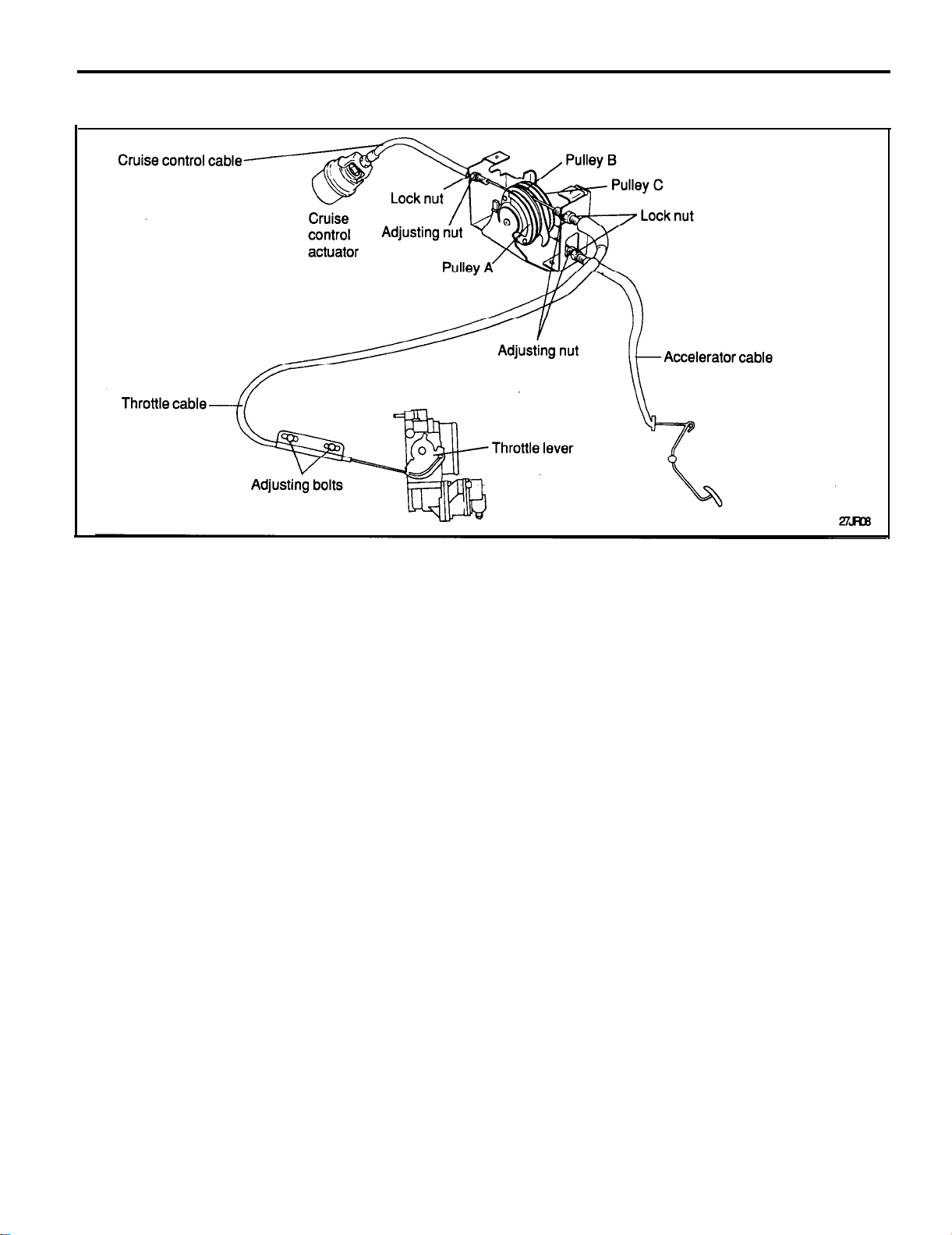
1. Pulley protector
2. Accelerator cable and pulley assembly connection
3. Cruise control cable and pulley assembly connection
4. Throttle cable and pulley assembly connection
5. Vacuum pump connector
6. Pump bracket and pump assembly
7. Pulley assembly
8. Accelerator cable and pedal connection
9. Accelerator cable
10. Throttle cable
11. Actuator
12. Vacuum hose
Page 44
27-44
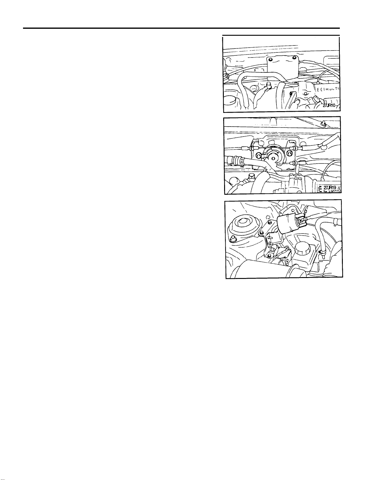
1. Remove the battery negative terminal.
2. Remove the pulley cover.
3.
Disconnect the accelerator cable and pulley assembly connec-
tion.
4.
Disconnect the cruise control cable and pulley assembly connec-
tion.
5.
Disconnect the throttle body cable and pulley assembly connection with turning throttle lever to full open position.
6.
Disconnect the vacuum pump connector and remove the
vacuum pump assembly.
CRUISE CONTROL
7.
Remove the actuator bracket and disconnect vacuum hose.
8.
Installation is the reverse order of removal.
Page 45
CRUISE CONTROL
CRUISE CONTROL CABLES INSPECTION AND ADJUSTMENT
27-45
Adjustment conditions
o
Turn A/C and all lights OFF.
Inspect and adjust at no load.
o
Warm engine until stabilized at idle.
Confirm idle speed is at specified RPM.
o Then, ignition switch OFF.
Inspection
1.
Confirm there are no sharp bends in cables.
2.
Depress the accelerator pedal and check if the throttle lever
moves smoothly from fully closed to fully open.
3.
Check inner cables for correct slack.
4.
If there is too much slack or no slack, adjust play by the following
procedures.
SERVICE HINT
1.
If the cable is very loose, the loss of speed going uphill will be
large.
2.
If the cable is too tight, the idle RPM will become high.
Page 46
27-46
CRUISE CONTROL
ADJUSTMENT
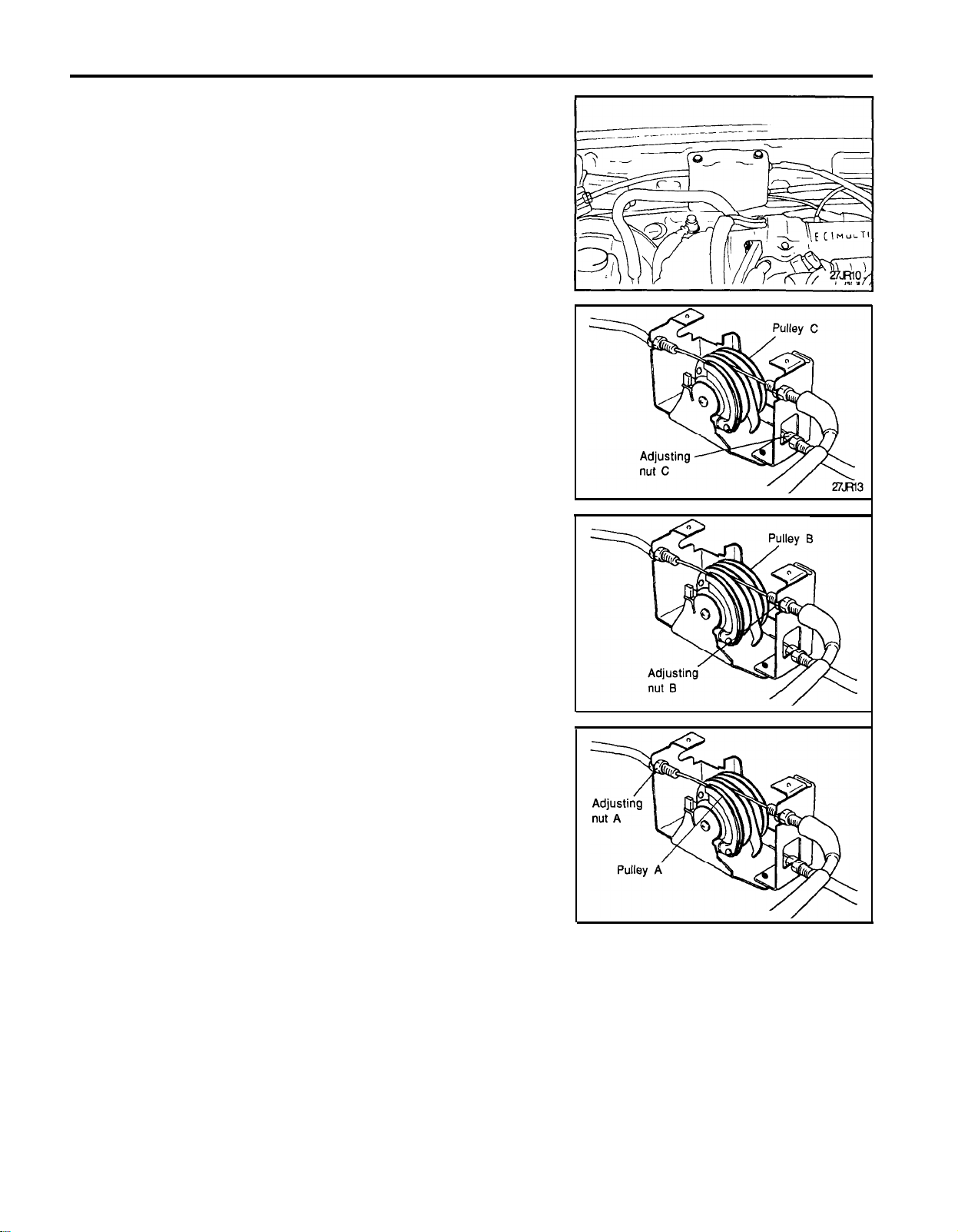
1.
Remove the cover of actuator.
2.
Loosen the adjusting nuts and lock nuts of the throttle lever and
intermediate pulley A, B and C, so that the intermediate pulley
A, B and C and the throttle lever can move freely.
3.
Turn the ignition switch to the ON position (without starting the
engine).
4.
Rotate the intermediate pulley C in the direction shown in the
diagram, and while keeping it touching the stopper, tighten the
adjusting nut C in the direction to lessen the inner cable play of
the accelerator cable. Then unscrew the adjusting nut C the
specified number of turns just before the intermediate pulley C
begins to move.
Amount to unscrew the adjusting nut C:
<A/T> 2-3 mm (0.08-0.12 inch)
Approx. 1/2 turns
<M/T> 0-1 mm (0-0.04 inch)
5.
Fix the accelerator cable with lock nut.
6.
Tighten the adjusting nut B in the direction to lessen the inner
cable play of the throttle cable. At the position where the
intermediate pulley B lever touches the intermediate pulley C,
unscrew the adjusting nut B the specified number of turns.
Amount to unscrew the adjusting nut B:
Approx. 1 turn [inner cable play 1-2 mm (.04-.08)]
7.
Fix the throttle cable with the lock nut.
8.
Tighten the adjusting nut A in the direction to lessen the inner
cable play of the cruise control cable. At the position where the
intermediate pulley A lever touches the intermediate pulley B,
unscrew the adjusting nut A the specified number of turns.
Amount to unscrew the adjusting nut A:
Approx. 1 turn [inner cable play 1-2 mm (.04-.08 in.)]
9.
Fix the cruise cable with the lock nut.
10. After adjusting, check if the end of the fixed SAS is touching the
throttle lever stopper.
Page 47
CRUISE CONTROL
TROUBLESHOOTING
BEFORE TROUBLESHOOTING
Before commencing troubleshooting, inspect each of the following
sections, and if there is an abnormality, carry out a repair.
(1)
Check if the installation and connection routes of the cables and
vacuum hoses of the cruise vacuum pump assembly,
actuator and pulley assembly are all normal.
(2) Check if the pulley assembly and the movement of all cables
are all working smoothly.
(3) Check if there is no excessive play or tension in each cable.
27-47
SELF-DIAGNOSIS CHECKING
Self-diagnosis checking is performed when there has been an
automatic cancellation, without cancel switch operation.
1.
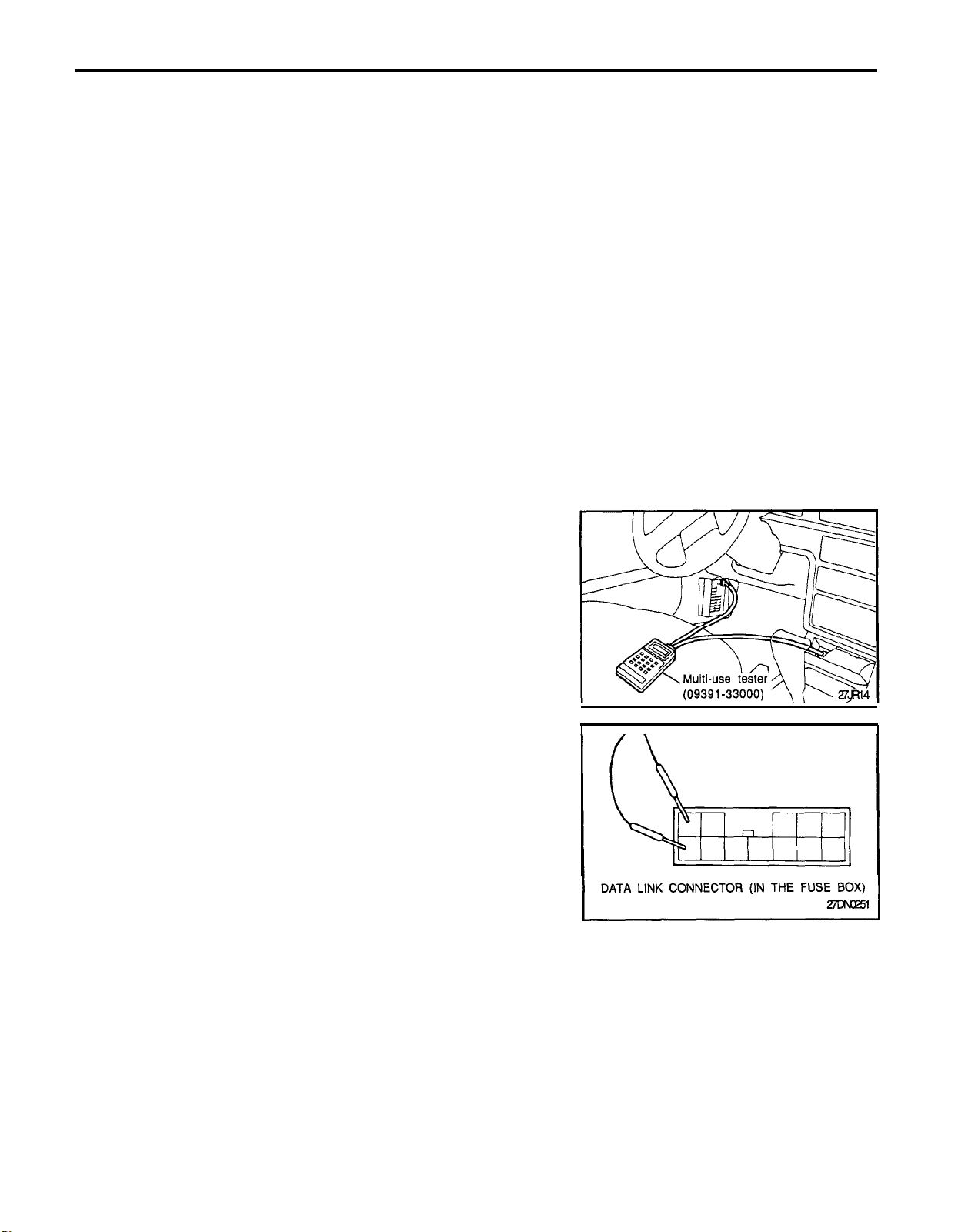
The following two methods can be used for checking the
diagnosis. Note that the data link connector is located in the
fuse box.
1)
If a multi-use tester is used.
Connect the scan socket and connector to the cigarette
lighter socket and the data link connector, and set the scan
tool.
Use the scan tool according to its operation instructions;
display the diagnosis code number and then check.
2)
If a indicator lamp is used.
Connect directly between the ground terminal and the
terminal for CC of the data link connector.
It is possible to discover which circuit is the cause of the
cancellation by verifying the indication shown by the indi-
cator lamp with the display patterns shown on the next
page.
CAUTION
The ignition switch should be turned OFF when con-
necting and disconnecting the scan tool.
2.
All diagnostic trouble codes are stored so that it is possible to
check if a problem occurred in the pastor not until disconnecting
the battery terminals, even when the ignition key is turned to
OFF.
CC : Cruise Control
Page 48
27-48
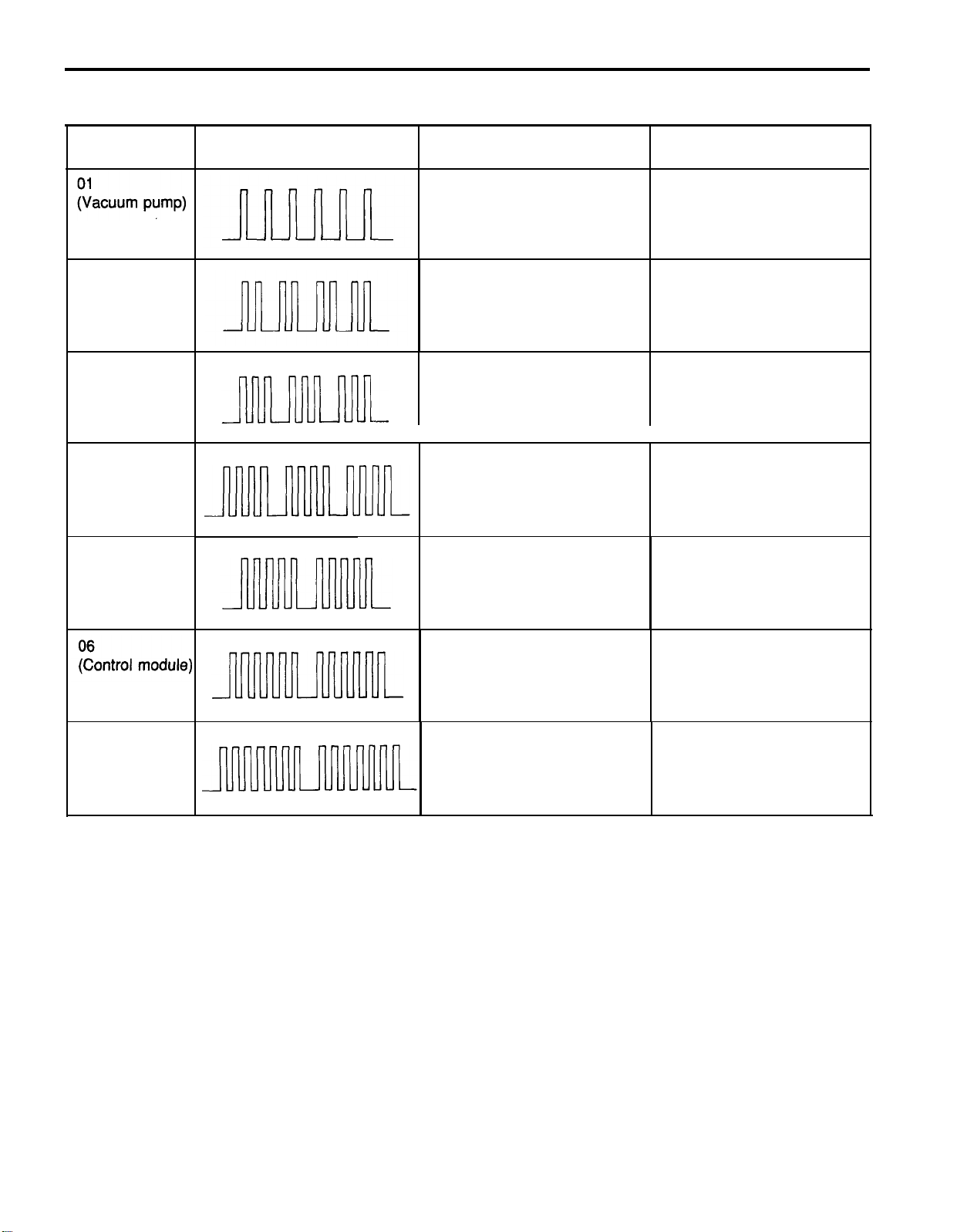
3. Diagnosis display patterns and codes
CRUISE CONTROL
CODE NO.
02
(Speed sensor)
03
(Low speed
limit)
04
(Redundant
brake)
05
(Control switch)
DISPLAY PATTERNS
(Use with check light)
PROBABLE CAUSE
Abnormal condition of auto cruise
vacuum pump drive system 2. Cruise CCM
Abnormal condition of vehicle 1. Vehicle speed sensor
speed signal system
Vehicle speed less than 40km/h
Vehicle speed less than memory
speed by 15km/h
SET and RESUME switches on
simultaneously
CHECK ITEMS
1. Vacuum pump assembly
3. Relevant wiring
2. Relevant wiring
07
(Cancel signal)
Abnormal condition of cruise 1. Cruise CCM
CCM
Cancel switch ON
2. Relevant wiring
1. Brake switch
2. P/N position switch
3. Clutch switch
4. Relevant wiring
Page 49

CRUISE CONTROL
TROUBLESHOOTING PROCEDURES
First, select the applicable malfunction symptom from the Trouble
Symptom Charts. Conduct the self-diagnostic test following the
directions on the charts.
Determine the condition of all function circuits.
CAUTION
Because the computer (self-diagnosis) memory data will be
erased, when the system is unintentionally canceled during
fixed-speed driving, the ignition switch and/or the cruise
main switch of the CCC system should not be switched OFF,
and the battery should not be disconnected.
Make the following preliminary inspections.
1.
1)
Check that the installation of the actuator, accelerator
cables are correct, and that the cables and links are
securely connected.
2)
Check that the accelerator pedal moves smoothly.
3)
Adjust the cable so there is no excessive tension or
excessive play on the accelerator cable.
4)
Check that the CCM, actuator, cruise main and control
switch and the connector of each cancel switch are
connected securely.
2.
Check in the sequence indicated in the Trouble Symptom
Chart.
3.
If these checks indicate a normal condition, replace the cruise
control module.
27-49
Page 50
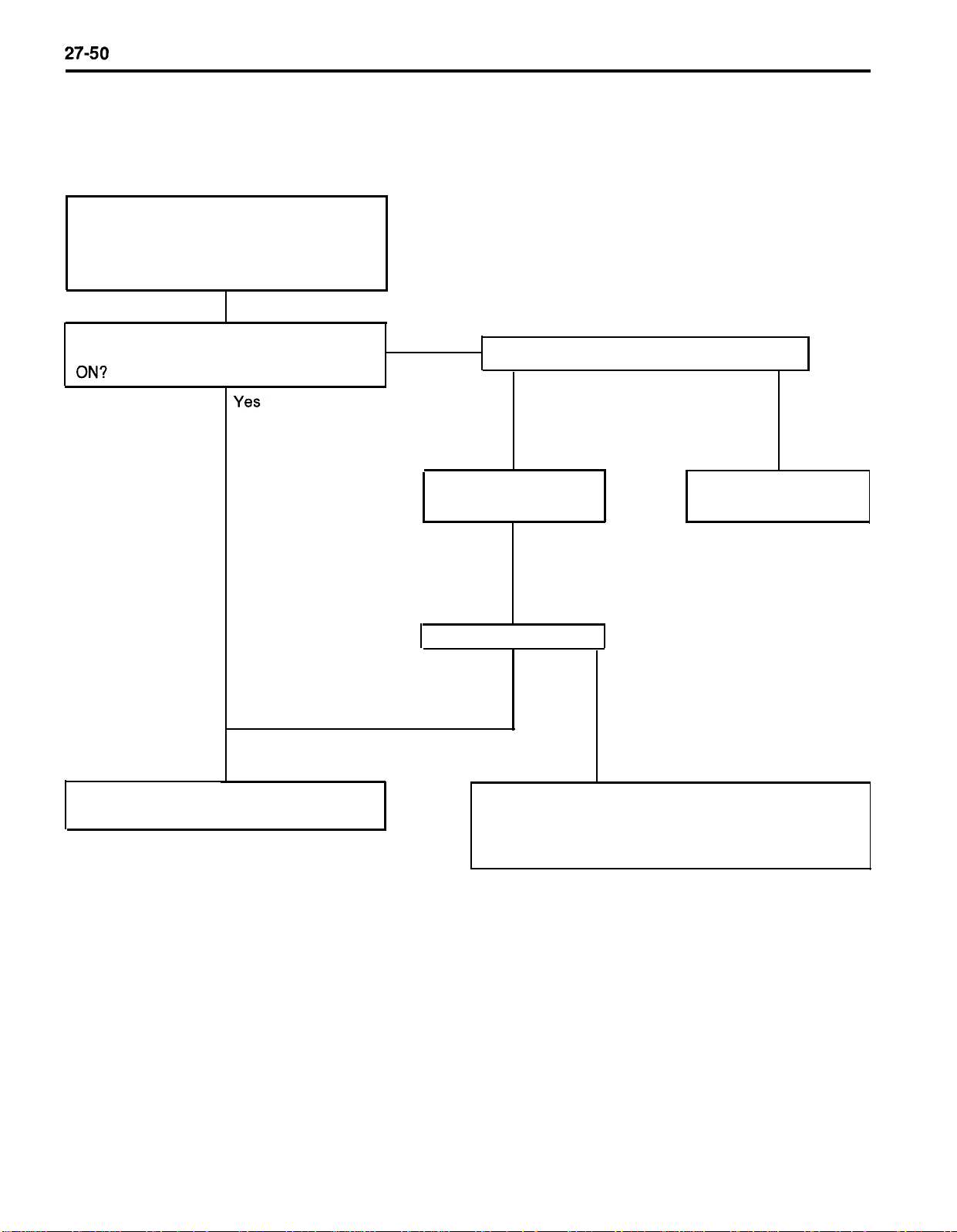
TROUBLE SYMPTOM CHARTS
Trouble Symptom 1
CC symptom is canceled when cancellation
not wanted.
Or, the CC system cannot be set after an
automatic cancellation.
CRUISE CONTROL
After the occurrence of the problem, was the
ignition switch and cruise main switch left
No
Yes No
Set the-CC system and
conduct a road test.
Did the problem reoccur?
Yes
Can the CC System be set now?
Check for trouble codes.
No (now normal)
With the cruise main switch ON and the
engine running, check for trouble codes.
CC : Cruise Control
Check whether or not, the vehicle was driven on a steep
slope, or the SET and RESUME control switches were
operated simultaneously. (The cause is not clear under
the present circumstances.)
Page 51
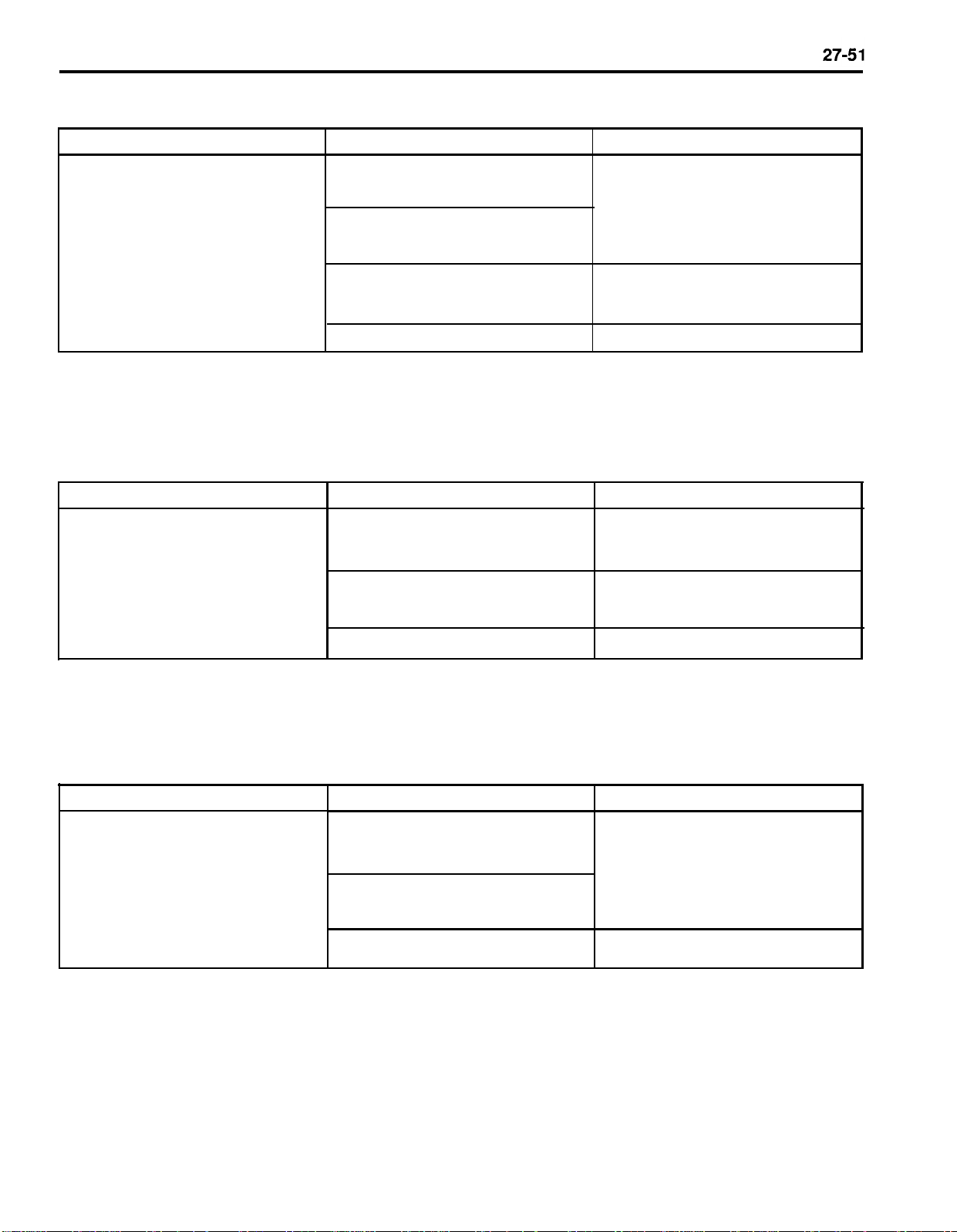
Trouble Symptom 2
CRUISE CONTROL
Trouble symptom
o The set vehicle speed varies
greatly upward or downward
o “Surging” (repeated alternating
acceleration and deceleration)
occurs after setting
Trouble Symptom 3
Trouble symptom
The CC system is not canceled when
the brake pedal is depressed
Probable cause
Malfunction of the vehicle
speed sensor circuit
Malfunction of the speedometer
cable or speedometer drive gear
Cruise vacuum pump circuit poor
contact
Malfunction of the CCM
Probable cause
Damaged or disconnected wiring of
the stop lamp switch
Cruise vacuum pump drive circuit
short-circuit
Remedy
Repair the vehicle speed sensor
system, or replace the part
Repair the actuator system, or
replace the part
Replace the CCM
Remedy
Repair the harness or replace the
stop lamp switch
Repair the harness or replace the
vacuum pump
Trouble Symptom 4
Trouble symptom
The CC system is not canceled when
the shift lever is moved to the “N”
position
(it is canceled, however, when the
brake pedal is depressed)
Malfunction of the CCM
Probable cause
Damaged or disconnected wiring
of inhibitor switch input circuit
improper adjustment of inhibitor
switch
Malfunction of the CCM
Replace the CCM
Remedy
Repair the harness or repair or re-
place the inhibitor switch
Replace the CCM
Page 52
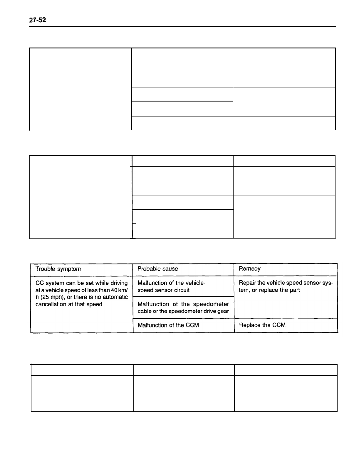
Trouble Symptom 5
CRUISE CONTROL
Trouble symptom
Cannot decelerate (coast) by using
the SET switch
Trouble Symptom 6
Trouble symptom
Cannot accelerate or resume speed
by using the RESUME switch
Probable cause
Temporary damaged or disconnected wiring of SET switch input
circuit
Actuator circuit poor contact
Malfunction of the actuator
Malfunction of the CCM
Probable cause
Damaged or disconnected wiring, or
short circuit, or RESUME switch in-
put circuit
Actuator circuit poor contact
Malfunction of the actuator
Remedy
Repair the harness or replace the
SET switch
Repair the harness or renlace the
actuator
Replace the CCM
Remedy
Repair the harness or replace the
RESUME switch
Repair the harness or replace the
actuator
Malfunction of the CCM
Trouble symptom 7
Trouble Symptom 8
Trouble symptom
The cruise main switch indicator lamp
Probable cause Remedy
Damaged or disconnected bulb of
does not illuminate cruise main switch indicator lamp
(But CC system is normal.)
Harness damaged or disconnected
Replace the CCM
Repair the harness or replace the
part.
Page 53
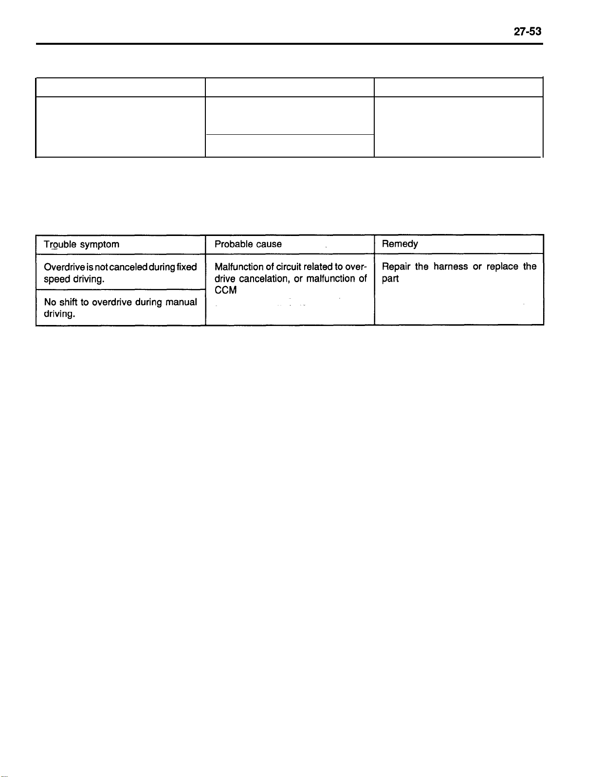
Trouble Symptom 9
CRUISE CONTROL
Trouble symptom
Malfunction of control function by
ON/OFF switching of idle switch
Trouble Symptom 10
Probable cause
Malfunction of circuit related to idle
switch function
Malfunction of the CCM
Remedy
Repair the harness or replace the
part
Page 54
27-54
CRUISE CONTROL
PARTS INSPECTION
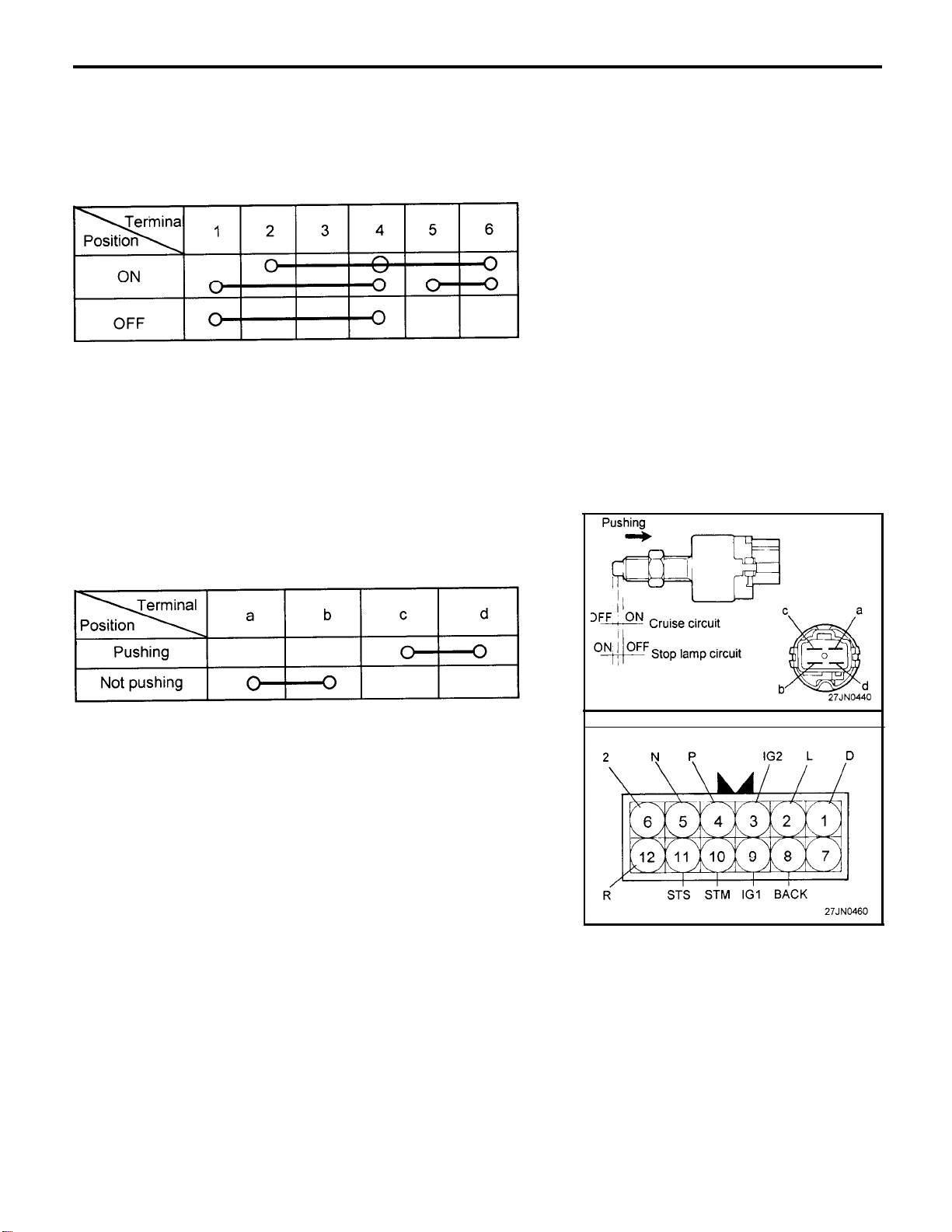
CRUISE CONTROL MAIN SWITCH
1.
Operate the switch, and check for the continuity between the
terminals.
2.
If continuity is not as specified, replace the switch.
STOP LAMP SWITCH
After operating the stop lamp switch, check for continuity between
the terminals.
P/N POSITION SWITCH
1. Disconnect the connector.
2.
Check that there is continuity between connector terminals 10
and 11 when the shift lever is moved to the “N” range.
Page 55
CRUISE CONTROL
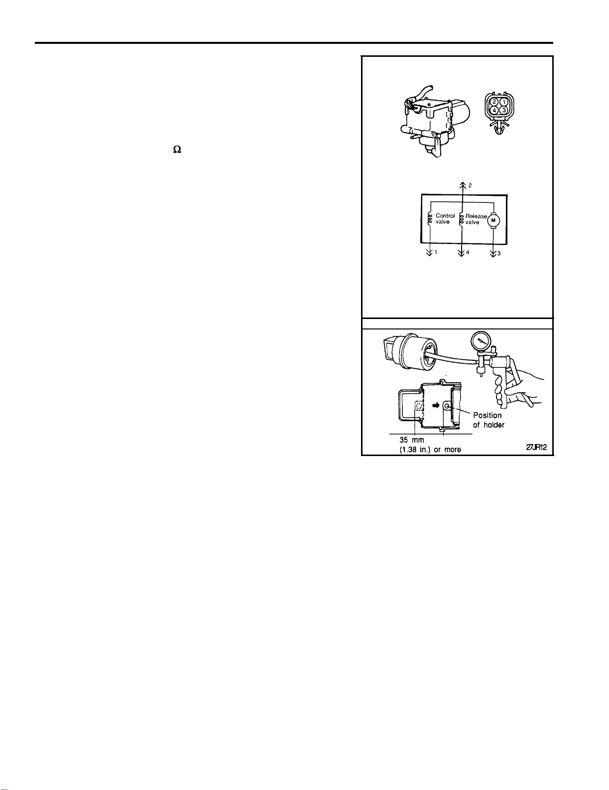
CRUISE VACUUM PUMP
INSPECTION OF SOLENOID VALVE (CONTROL
VALVE, RELEASE VALVE)
1.
Remove the auto-cruise vacuum pump connector.
2.
Measure the resistance value between connector terminal 1
and 2, and connector terminals 2 and 4.
Standard value : 50-60
3.
Check that the solenoid valve makes an operating noise when
battery voltage is impressed between terminals 2 and 1, and
connector terminals 2 and 4.
4.
if there is a malfunction of the solenoid valve, replace the cruise
vacuum pump assembly.
MOTOR INSPECTION
1.
Remove the cruise vacuum pump connector.
2.
Check that the motor revolves when battery voltage applyed
between connector terminals 2 and 3.
27-55
ACTUATOR
1. Remove the actuator.
2.
Apply negative pressure to the actuator with the vacuum pump
and check that the holder moves more than 35 mm (1.38 in.).
in addition, check that there is no change in the position of the
holder when negative pressure is maintained in that condition.
3.
First install the actuator and then inspect and adjust the cruise
control cable.
Page 56

 Loading...