


D525ML_ENG_01.indd 1 2008.9.4 1:33:27 PM

U.S.A.
U.S.FEDERAL COMMUNICATIONS COMMISSION
RADIO FREQUENCY INTERFERENCE STATEMENT
INFORMATION TO THE USER
NOTE : This equipment has been tested and found to comply with the limits for a Class B digital device pursuant to Part 15
of the FCC Rules.
These limits are designed to provide reasonable protection against harmful interference in a residential installation.This
equipment generates, uses, and can radiate radio frequency energy and, if not installed and used in accordance with the
instructions, may cause harmful interference to radio communications.
However, there is no guarantee that interference will not occur in a particular installation.
If this equipment does cause harmful interference to radio or television reception, which can be determined by turning the
equipment off and on, the user is encouraged to try to correct the interference by one or more of the following measures:
• Reorient or relocate the receiving antenna.
• Increase the separation between the equipment and receiver.
• Connect the equipment into an outlet of a circuit different from that to which the receiver is connected.
• Consult the dealer or an experienced radio/TV technician for assistance.
Changes or modification not expressly approved by the party responsible for compliance could void the user's authority to
operate the equipment.
Connecting of peripherals requires the use of grounded shielded signal cables.
D525ML_ENG_01.indd 2 2008.9.4 1:33:30 PM

DIGITAL SIGNAGE
DECLARATION OF CONFORMITY
WE HYUNDAI IT CORP.
Ami-ri Bubal-Eub Ichon-Si Kyungki-Do
467-860 KOREA
declare under our sole responsibility that the product:
to which this declaration relates is in conformity with the following
standard(s) or other normative document(s)
following the provisions of the Low Voltage Directive 73/23/EEC,
93/68/EEC and the EMC Directive 89/336/EEC.
Jong Won, Choi Ho Suk, Chon
(Name and signature of authorized person)
KOREA / July 1, 2008
(Place and date of issue)
Kind of equipment : DID
Type-Designation : S40M0G010 / LT46DW001 / S57M0F010
Safety : EN60950-1:2002
EMC : EN 55022/1998+A1:2000+A2:2003
EN 55024 :1998+A1:2001+A2:2003
EN 61000-3-2:2000
EN 61000-3-3:1995+A1:2001
TUV SUD Product Service GmbH
Zertifizierstelle, Ridlerstrasse
65, 80339 Munchen, Germany
Accredited testlaboratory
TÜV Rheinland
Am Grauen Stein
51105 Köln
LT46DW001 :
S40M0G010 :
S57M0F010
D525ML_ENG_01.indd 3 2008.9.4 1:33:31 PM

DIGITAL SIGNAGE
Major features ...................................................... 1/34
Direction for the use ........................................... 1/34
Be sure to understand ......................................... 3/34
Checking product list .......................................... 5/34
Proper place for product
Installation
........................................................... 6/34
Title and function of each part .......................... 7/34
Front part .............................................................. 7/34
Rear part .............................................................. 8/34
Remote control ...................................................... 9/34
How to insert battery into remote control .............. 9/34
How to connect HDMI ....................................... 10/34
Support timing for Digital RGB ........................... 11/34
Corrections
How to connect analog RGB (PC D_SUB) ........12/34
Supporting timing for PC ..................................13/34
How to Connect component ..........................14/34
Supporting timing for component & AV ............15/34
How to Connect the video ..............................16/34
OSD adjustment and fucntion .........................17/34
Diagnosis ...........................................................31/34
Product specification .......................................33/34
ENGLISH
D525ML_ENG_01.indd 4 2008.9.4 1:33:33 PM

DIGITAL SIGNAGE
-1/34-
DIGITAL SIGNAGE
Major features
Direction for the use
This product has been designed to enable the user ease of use, and display information
effectively and conveniently.
• TFT LCD Module adopted
D320ML/D400ML/D420ML/D460ML : 1366 x 768 WXGA (HD)
D525ML/D575ML/D705ML : 1920 x 1080 UWXGA (FHD)
• vivid digital color display
• OSD control function
• Automatic Image control
• Automatic temperature control
• Analog/Digital RGB(HDMI) input and output
• Y Pb Pr/AV input and output
• Built in multi-vision function
This Product is designed to ensure user's safety.
Avoid the following items prevents from serious electric shot and other dangers.
- Do not place wet objects on or around the product or the power cord.
- Do not cover or insert anything over or into the ventilation openings.
- Do not place in a location where damaged from oil, Smoke, high temperature, high
humidity, dust etc can be caused.
D525ML_ENG_01.indd 1 2008.9.4 1:33:33 PM

DIGITAL SIGNAGE
-2/34-
ENGLISH
- The product is not suitable for use at visual display workplaces according to §2
of the German Ordinance for Work with Visual Display Units.
- The mains plug of the power supply cord shall remain readily operable.
- An apparatus with CLASS I construction shall be connected to a Mains socket outlet
with a protective earthing connection.
- Make sure the power cord and other cables are correctly plugged in.
- Plug the power cord correctly into the end, do not wobble/jiggle, it may cause electric shock fire.
- Do not touch the power cord with wet hands, it may cause electric shock.
- Overloaded AC outlets and extension cables are as dangerous as the power cord being
damaged, call service engineer for replacement as it may cause electric shock or fire.
- Do not use multiple devices in a single power outlet, it may cause overheating or fire.
- Do not use or place sharp objects near the LCD surface, as this can cause damage to the screen
itself.
- When cleaning the LCD screen / Surface, do not use chemical cleaning products as this can
seriously damage the special coatings on the screen. Only use water to dampen a soft cloth
and lightly clear the screen.
- Over time dust deposits can build up inside the product, this can cause the product to overheat
thus causing premature malfunction or fire. Please do not attempt to clean the inside of the
product yourself, please contact the local service agent.
- Do not use alcohol or strong chemical solvent such as methyl, ethyl or a Isopropyl.
- In the case of cleaning, be sure to remove the power cord and wip with a soft dry fabric.
- Keep batteries for the remote control out of children's sight.
- Make sure that power cord or other cables are correctly plugged in.
D525ML_ENG_01.indd 2 2008.9.4 1:33:34 PM

DIGITAL SIGNAGE
-3/34-
DIGITAL SIGNAGE
Be sure to
understand
- Batteries should be inserted using the correct polarity (+,-).
- Use only new batteries, do not mix old & new.
- Place unit on a stable bracket or surace.
- More than 2 persons should work together when moving or installing.
- Do not hang on or jump to the product or mounting rack.
- When the product be left unused for a long time, be sure to unplug the power cord.
- In the case of damage or breakage do not attempt to self repair, please contact local
service engineer.
Image quality of the product
CAUSE
- Due to the nature of LCD's property, Afterimage can occur. Afterimage appears when
identical frames / images are displayed continuasly. If displayed for prolonged periods
of time this can become permanent.
PREVENTION
When you display a freeze frame for a long time, lower the brightness and contrast
(Brightness, 70/ Contrast, 80). Also it can be prevented by using moving frame.
D525ML_ENG_01.indd 3 2008.9.4 1:33:34 PM

DIGITAL SIGNAGE
-4/34-
ENGLISH
PREVENTION
Temporary afterimage can be alleviated by displaying white or moving frame about 10
hours.(But, permanent afterimage cannot be disappeared according to the property of
LCD) This method is used to remove temporary afterimage that may occur after
displaying a still frame for a certain times.
It can take several minutes or hours to remove afterimage according to the severity. In
the case that your cannot avoid displaying identical still image continuously, you can
prevent it by displaying moving image for 2 or 3 minutes in every hour. As the
brightness of still image and time of display are the cause of afterimage, you are
recommended to lower the brightness in that case.
Above problem shall not be covered by warranty.
!
D525ML_ENG_01.indd 4 2008.9.4 1:33:34 PM

DIGITAL SIGNAGE
-5/34-
DIGITAL SIGNAGE
Please check the following components provided with the product after you open the box.
please check the following components provided with the product after you open
the box and contact the dealer if any missing.
Check the product
list
!
HDMI cable
Remote control &
batteries
Power Cord
User's manual
Product
HDMI to DVI Cable
(Option)
D-SUB Cable
(Option)
RS232C Cable
(Option)
D525ML_ENG_01.indd 5 2008.9.4 1:33:36 PM

DIGITAL SIGNAGE
-6/34-
ENGLISH
Proper location for
product installation
1. Locate the product at least 30cm away from the electric appliance or heating product.
2. The product must be placed at least 10cm away from the wall and ground.
3. Keep the product out of direct ray of light and locate screen not to be reflected by the
sunlight.
4. Make sure the mounting rack firmly tightened before installation.
Please take extra care during installation, it is possible to cause damage if the unit is
handled badly or knocked.
!
D525ML_ENG_01.indd 6 2008.9.4 1:33:37 PM

DIGITAL SIGNAGE
-7/34-
DIGITAL SIGNAGE
Title and function of
each part
Front panel
A
Remote control receiving sensor.
2
Power display LED red-stand by/ Green-working.
3
~ OSD button.
3
Power button ; to turn the power on or off.
4
Input selection button : to select other connected
device.
5
Menu button : to display menu or exit from the menu.
6
select button.
7
To move down in OSD menu.
8
To move up in OSD menu.
9
To move left and control the volume down in OSD menu.
To move right and control the volume up OSD menu.
A
2 3 4 5 6 7 8 9
POWER
SOURCE MENU
SELECT
VOL
J
J
J
D525ML_ENG_01.indd 7 2008.9.4 1:33:38 PM
DIGITAL SIGNAGE
-8/34-
ENGLISH
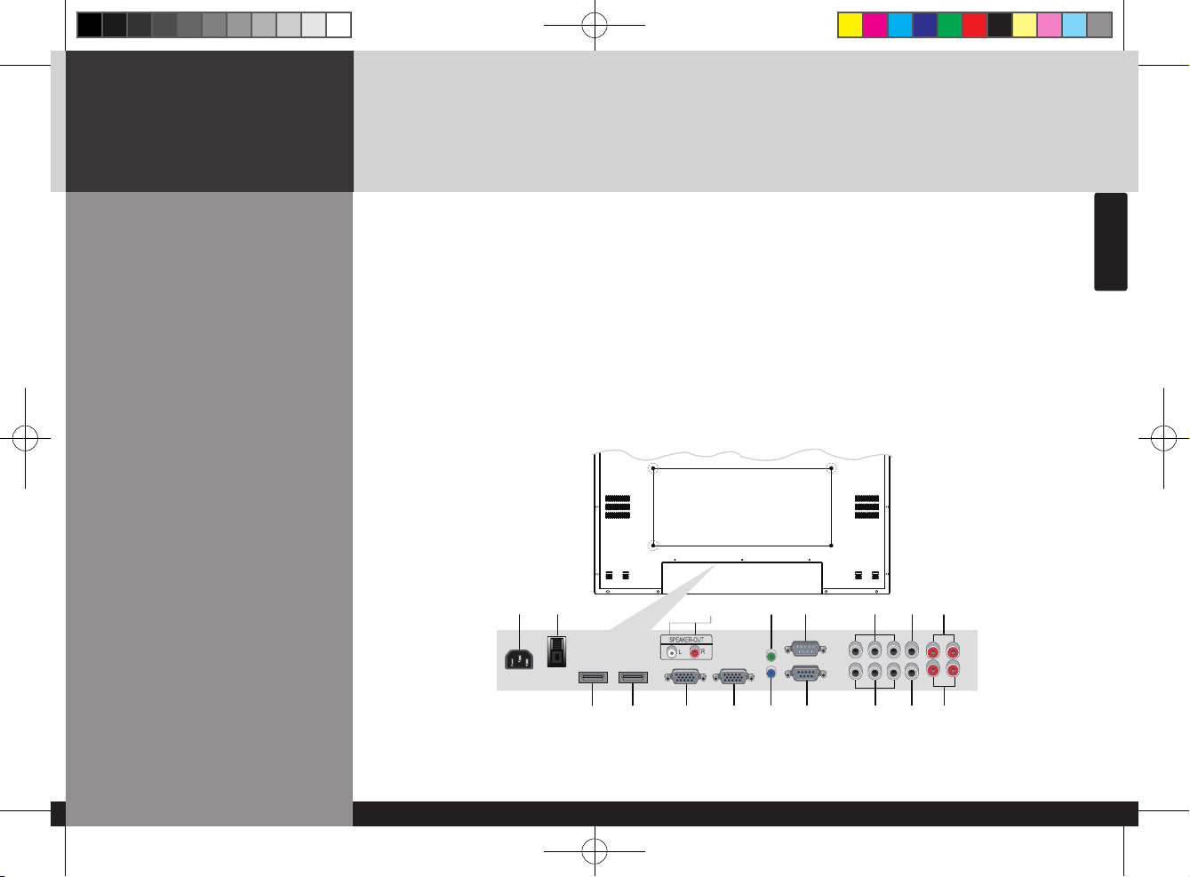
Rear panel
A
AC IN
2
AC POWER SWITCH
3
HDMI IN
4
HDMI OUT
5
SPEAKER OUT
6
PC D-SUB IN
7
PC D-SUB OUT
8
UPGRADE
9
PC AUDIO IN
J
RS-232C OUT
K
RS-232C IN
L
COMPONENT IN (Y Pb Pr)
M
COMPONENT OUT (Y Pb Pr)
CVBS IN
CVBS OUT
COMPONENT AUDIO IN (L R)
COMPOSITE AUDIO IN (L R)
A
8
K
M
2
3
5
6
J
L
74
9
D525ML_ENG_01.indd 8 2008.9.4 1:33:39 PM

DIGITAL SIGNAGE
-9/34-
DIGITAL SIGNAGE
Remote control
How to insert batteries
Pull while pressing ∆ at rear lid. Insert the batteries into proper polarities
(+,-).
Use after the lid closed.
1 2 3
A
To turn the power on or off.
2
Move up in OSD menu.
3
To move left or control the volume down in OSD
menu.
4
To move right or control the volume up in OSD menu.
5
To move down in OSD menu.
6
Select in OSD menu.
7
Display the menu screen.
8
Close the menu screen.
9
Convert the input signal.
A
2
3 4
5
6
7
8
9
D525ML_ENG_01.indd 9 2008.9.4 1:33:41 PM

DIGITAL SIGNAGE
-10/34-
ENGLISH
How to Connecting
Digital RGB(HDMI)
1. Please ensure that the power to the device is switched off, then connect each cable
one after another before restoring power.
A
when connect HDMI to HDMI cable
2
when connect DVI to HDMI cable
– must utilize device with DVI signal output from peripheral device
2. Connect the power code to the product.
3. Turn on the power of product and peripheral device. Screen shows up within 10
seconds.
4. Select "HDMI" input by pressing "SOURCE" on OSD button or remote control.
– HDMI input gives better video quality than analog RGB input.
– Both HDMI and analog RGB support plug and play.
A
2
D525ML_ENG_01.indd 10 2008.9.4 1:33:42 PM

DIGITAL SIGNAGE
-11/34-
DIGITAL SIGNAGE
Support timing for
HDMI
9, 10, 11 and 12 are only for Full HD
1
2
3
4
5
6
7
8
9
10
11
12
480p
576p
720p
1080i
640 x 480
800 x 600
1024 x 768
1360 x 768
1280 x 1024
1600 x 1200
1920 x 1080
1080p
640 x 480p
720 x 576p
1280 x 720p
1920 x 1080i
31.47
37.88
48.36
47.70
64.00
75.00
67.50
1920 x 1080p
60
50
50 / 60
50 / 60
59.94
60.32
60
60
60
60
60
60
Vertical frequency
(Hz)
Horizontal frequency
(KHz)
Resolution
NO
!
D525ML_ENG_01.indd 11 2008.9.4 1:33:43 PM

DIGITAL SIGNAGE
-12/34-
ENGLISH
1. Please ensure that the power to the device is switched off, then connect each cable one
after another before restoring power.
2. Connect D-SUB to D-Sub cable. Then tighten the screw of the cable after connecting PC
D-SUB.
3. Connect the power cord to the product.
4. Turn on the power of product and PC . The screen will appear within 10 seconds.
5. Select "PC" input by pressing "SOURCE" on OSD button or remote control.
– HDMI input gives better video quality than analog RGB input.
– Both HDMI and analog RGB support plug and play.
How to Connecting
analog RGB
(PC D-SUB)
D525ML_ENG_01.indd 12 2008.9.4 1:33:44 PM

DIGITAL SIGNAGE
-13/34-
DIGITAL SIGNAGE
Support timing for PC
1
2
3
4
5
6
7
640 x 480
800 x 600
1024 x 768
1360 x 768
1280 x 1024
1600 x 1200
1920 x 1080
31.47
37.88
48.36
47.71
64.00
75.00
67.50
59.94
60.32
60.00
60.00
60.00
60.00
60.00
Vertical frequency(Hz)
Horizontal frequency(KHz)
ResolutionNO
!
5, 6 and 7 are only for Full HD
D525ML_ENG_01.indd 13 2008.9.4 1:33:44 PM

DIGITAL SIGNAGE
-14/34-
ENGLISH
1. Please ensure that the power to the device is switched off, then connect each cable one
after another before restoring power.
2. Connect the component cables to Y, Pb, and Pr correctly.
Connect BNC cable and tighten.
3. Connect the power cord to the product.
4. Turn on the power of product and peripheral device .
The screen will appear within 10 seconds.
5. Select "COMPONENT" input by pressing "SOURCE" on OSD button or remote control.
How to Connecting
the component
D525ML_ENG_01.indd 14 2008.9.4 1:33:46 PM

DIGITAL SIGNAGE
-15/34-
DIGITAL SIGNAGE
Support timing for
component & AV
1
2
3
4
5
6
7
480i
480p
576i
576p
720p
1080i
1080p
720 x 480i
640 x 480p
420 x 480p
720 x 576i
720 x 576p
1280 x 720p
1920 x 1080i
1920 x 1080p
59.94 / 60
59.94 / 60
59.94 / 60
50
50
59.94 / 60 / 50
59.94 / 60 / 50
60 / 50
Vertical frequency
(Hz)
Horizontal frequency
(KHz)
Resolution
NO
!
7 is only for Full HD
D525ML_ENG_01.indd 15 2008.9.4 1:33:46 PM

DIGITAL SIGNAGE
-16/34-
ENGLISH
How to Connecting
the the video
1. Please ensure that the power to the device is switched off, then connect each cable
one after another before restoring power.
2. Connect video cable and BNC cable, and then tighten.
3. Connect the power cord to the product.
4. Turn on the power of product and peripheral device .
The screen will appear within 10 seconds.
5. Select AV input by pressing "SOURCE" on OSD button or remote control.
D525ML_ENG_01.indd 16 2008.9.4 1:33:47 PM

DIGITAL SIGNAGE
-17/34-
DIGITAL SIGNAGE
Adjusting OSD and
explanation of its
function
How to Select the
Picture Mode
Users can automatically adjust the picture mode
according to the input mode.
1. Press Menu button. Menu items appear on the screen.
2. Press ↲ button to select "Picture" Icon. "PICTURE MODE" is highlighted.
3. Press ▶ or ↲ buttons to select "Picture mode".
4. The menu changes in the following order.
AV/Component input : Custom -> Dynamic -> Standard -> Movie -> Mild
PC/HDMI Input : Custom -> High -> Middle -> Low
5. Press EXIT button to escape OSD MENU or press MENU button to return to the previous menu.
- Custom : When the user wants to set the values directly.
- Dynamic : Clear display
- Standard : Most video contents are appropriate to this mode.
- Movie : When watching a movie
- Mild : Soft display.
D525ML_ENG_01.indd 17 2008.9.4 1:33:49 PM

DIGITAL SIGNAGE
-18/34-
ENGLISH
How to Set the Desired
Picture
Users can manually adjust their desired picture
1. Press Menu button.
Menu items appear on the screen.
2. Press ↲ button to select Picture Icon.
"PICTURE MODE" is highlighted.
3. Press ▲ / ▼ buttons to move to Custom and press ▶or
↲ buttons to select “CUSTOM”.
4. Select required option by pressing the ▲ / ▼ or button,
then Press◀ / ▶ button to adjust.
5. Press EXIT button to escape OSD MENU or press MENU
button to return to the previous menu.
- BRIGHTNESS : Adjust the brightness of the entire picture.
- CONTRAST : Adjust the brightness and darkness of the object and backgrounds.
- COLOUR : Adjust colors into deeper or lighter colors.(not operational in pc and HDMI mode)
- TINT : Adjust colors naturally.(not operational in pc, HDMI and component mode)
- SHARPNESS : Adjust the clarity of object outlines.(not operational in pc and HDMI mode)
D525ML_ENG_01.indd 18 2008.9.4 1:33:49 PM
DIGITAL SIGNAGE
-19/34-
DIGITAL SIGNAGE
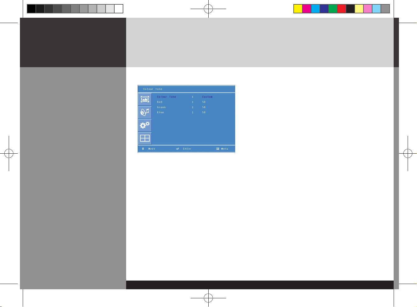
Users can adjust Color as users want.
1. Press Menu button.
Menu items appear on the screen.
2. Press ↲ button to select Picture Icon.
"Picture Mode" is highlighted.
3. Press ▲ / ▼ buttons to move to "Color Tone"
4. Press ▶ or ↲ buttons to select "Color Tone" .
5. Press ▲ / ▼ buttons, then the menu changes in the
following order.
Custom -> Cool2 -> Cool1 -> Normal
-> Warm1 -> Warm2
6. Press EXIT button to escape OSD menu or press MENU button to return to the previous
menu.
- Custom : When the user wants to set the degree of RGB directly.
- Cool : For cool colors with bluish tone.
- Normal : For a general Color Tone.
- Warm : For warm colors with reddish tone.
How to Select a Color
Tone
D525ML_ENG_01.indd 19 2008.9.4 1:33:50 PM

DIGITAL SIGNAGE
-20/34-
ENGLISH
Users can adjust the display scale as they want
How to Set the Display
Size
1. Press Menu button. Menu items appear on the screen.
2. Press ↲ button to select Picture Icon. "Picture Mode" is highlighted.
3. Press ▲ / ▼ buttons to move to "Size".
4. Press ◀ / ▶ or ↲ buttons and press ▲ / ▼ then the mode change in the following order.
AV/Component Inputs : Auto Size ->Wide -> Panorama -> Zoom -> 4 : 3 -> 14 : 9
PC input : Wide -> 4 : 3
DVI input : 4 : 3 -> Wide -> 1 : 1
5. Press EXIT button to escape OSD MENU or press MENU button to return to the previous menu.
- Auto Size - Screen size adjust automatically by screen signal.
- Wide - General broadcast picture is adjusted to 16:9.
- Panorama - Picture enlarged to 16:9 format, letter box format.
- Zoom - Zoom in 16:9 in vertical direction
- 4 : 3 - 4 : 3 general picture size
- 14 : 9 - 14 : 9 picture size
- 1 : 1 - 1 : 1 real size
D525ML_ENG_01.indd 20 2008.9.4 1:33:51 PM

DIGITAL SIGNAGE
-21/34-
DIGITAL SIGNAGE
How to Set Image
Adjust in PC Mode
(Supported only in PC
mode)
1. Press Menu button.
Menu items appear on the screen.
2. Press ↲ button to select "Picture" Icon.
"Picture Mode" is highlighted.
3. Press ▲ / ▼ buttons to move to PC and Press
▶ or ↲ buttons to select to "pc"
4. "Auto Adjust" is high lighted.
5. Press ↲ button to execute the "Auto Adjust"
6. Select required option by pressing the ◀ / ▶ or ↲
buttons, then press ◀ / ▶button to adjust
7. Press EXIT button to escape OSD MENU or press NEW button to return to the previous menu.
- Auto Adjust : Horizontal/vertical positions are automatically adjusted.
- Phase : To eliminate the shake of the picture.
- H-Position : To adjust the horizontal position of the picture.
- V-Position : To adjust the vertical position of the picture.
- Frequency : To eliminate the shake of picture.
D525ML_ENG_01.indd 21 2008.9.4 1:33:52 PM

DIGITAL SIGNAGE
-22/34-
ENGLISH
User can eliminate noises on the screen in AV/Component/HDMI mode.(Not supported in PC mode)
Users can adjust sound mode automatically as they want.
How to Set Noise
Reduction(NR)
How to Select the
Audio Mode
1. Press Menu button.
Menu items appear on the screen.
2. Press ↲ button to select Picture Icon.
"Picture Mode" is highlighted.
3. Press ▲ / ▼ buttons to move to "NR" .
4. Press ◀ / ▶ buttons to select to "NR".
5. Press ▲ / ▼ or ↲ buttons to set "On/Off".
6. Press EXIT button to escape OSD MENU or press
MENU button to return to the previous menu.
1. Press Menu button. Menu items appear on the
screen.
2. Press ▲ / ▼ buttons to move to "Sound" icon.
3. Press ↲ button to select "Sound" Icon. "Mode" is
highlighted.
4. Press ▶ or ↲ buttons, to select to "Sound Mode"
then the menu changes in the following order.
Custom->Standard -> Music -> Movie -> Speech
5. Press EXIT button to escape OSD MENU or press
MENU button to return to the previous menu.
- Custom : When the user wants to set the values directly.
- Standard : For the general sound. Most audio contents are appropriate to this mode.
- Music : For enjoying original sound.
- Movie : Grandiose sound.
- Speech : Clear sound.
D525ML_ENG_01.indd 22 2008.9.4 1:33:53 PM

DIGITAL SIGNAGE
-23/34-
DIGITAL SIGNAGE
Users can adjust sound mode automatically as they want.
How to Adjust the
Desired Audio Mode
1. Press Menu button. Menu items appear on the screen.
2. Press ▲ / ▼ buttons to move to "Sound" icon.
3. Press ↲ button to select "Sound" icon. "Mode" is highlighted.
4. Press ▲ / ▼ buttons to move to Balance or Equalizer .
5. Press ↲ buttons to select “Balance or Equalizer”. Balance or Equalizer menu appears.
6. Select required option by pressing the ▲ / ▼ buttons, then Press ◀ / ▶ buttons to adjust.
7. Press EXIT button to escape OSD MENU or press MENU button to return to the previous menu.
- Balance : Adjusts the balance of left and right speakers.
- Equalizer : Adjusts the audio output signal in the desired band.
D525ML_ENG_01.indd 23 2008.9.4 1:33:54 PM

DIGITAL SIGNAGE
-24/34-
ENGLISH
How to Select Auto
Volume
How to Select Sound
Mode
This function will automatically give a similar volume size to each channel.
1. Press Menu button.
Menu items appear on the screen.
2. Press ▲ / ▼ buttons to move to "Sound" icon.
3. Press ↲ button to select "Sound" icon.
"Mode" is highlighted.
4. Press ▲ / ▼ buttons to move to "Auto Volume".
5. Press ◀ / ▶ or ↲ buttons to select "On/Off".
6. Press ▲ / ▼ or ↲ buttons to set to "On/Off".
7. Press EXIT button to escape OSD MENU or press MENU
button to return to the previous menu
- Choose "Stereo" for channels that are broadcasting in Stereo.
- Choose "Mono" for channels that are broadcasting in Mono, or if you are having difficultly receiving
a Stereo signal.
1. Press Menu button.
Menu items appear on the screen.
2. Press ↲ button to select "Sound" Icon.
"Mode" is highlighted.
3. Press ▲ / ▼ buttons to move to "Sound Mode".
4. Press ▶ or ↲ buttons to select to "Sound Mode".
5. Press ▲ / ▼ buttons to select to "Mono" or "Stereo".
6. Press exit button to escape OSD MENU or press MENU
button to return to the previous menu
Depending on the particular program being broadcast, you can select stereo or mono.
D525ML_ENG_01.indd 24 2008.9.4 1:33:55 PM

DIGITAL SIGNAGE
-25/34-
DIGITAL SIGNAGE
How to Reset
How to Set Clock,Sleep
Time, ON/OFF Time
1. Press Menu button.
Menu items appear on the screen.
2. Press ↲ button to select Set up Icon.
"Reset" is highlighted.
3. Press ▶ or ↲ buttons to select to "Reset".
4. Press ↲ buttons to choose to "Reset".
5. Press EXIT button to escape OSD MENU or press MENU
button to return to the previous menu.
1. Press Menu button.
Menu items appear on the screen.
2. Press ↲ button to select "Set-Up" Icon.
"Reset" is highlighted.
3. Press ▲ / ▼ buttons to move to "Time".
4. Press ▶ or ↲ buttons to select "Time".
Time menu appears, then "Clock" is highlighted.
5. Press ◀ / ▶ buttons to move between Hour, Minute and
Press ▲ / ▼ buttons to set Hour, Minute.
When the power supply(AC main power) is cut off, the clock is reset to the value before the Timer set.
When you select "Reset" user setting Value will initialize.
D525ML_ENG_01.indd 25 2008.9.4 1:33:56 PM

DIGITAL SIGNAGE
-26/34-
ENGLISH
Choosing the Your
Languages
<Go to step 6 if you need to set the "On or Off Timer">
6. Press ▲ / ▼ buttons to move to "On or Off Timer".
7. Press ▶ or ↲ buttons to select "On or Off Timer" .
8. Press ◀ / ▶ buttons to move between Hour, Minute and
on/off and Press ▲ / ▼ buttons to set Hour, Minute and
on/off
<go to step 9 if you need to set the "On Time Volum">
9. Press ▲ / ▼ buttons to move to "On Time Volum".
10. Press ◀ / ▶ buttons to adjust Volume.
<go to step 11 if you need to set the "Source">
11. Press ▲ / ▼ buttons to move to "Source"
12. Press ▶ or ↲ buttons to select to "Source"
13. Press
▲ / ▼
buttons to set to Source
1. Press Menu button.
Menu items appear on the screen.
2. Press ↲ button to select "Setup" Icon.
"Reset" is highlighted.
3. Press ▲ / ▼ button to move to "Language" and press
▶ or ↲ button to select to Language.
4. Press EXIT button to escape OSD MENU or press MENU
button to return to the previous menu.
D525ML_ENG_01.indd 26 2008.9.4 1:33:57 PM
DIGITAL SIGNAGE
-27/34-
DIGITAL SIGNAGE
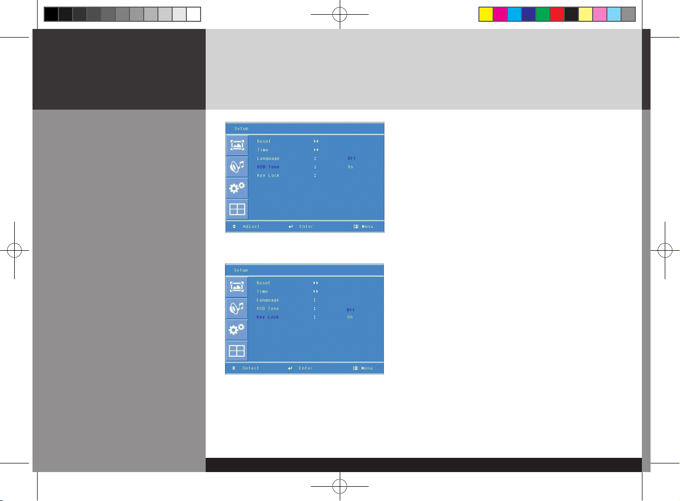
How to set osd tone
How to Set Key-Lock
1. Press Menu button.
Menu items appear on the screen.
2. Press ↲ button to select "setup" icon.
"Reset" is highlighted.
3. Press ▲ / ▼ buttons to move to "OSD tone"
4. Press ▶ or ↲ buttons to select to "OSD tone".
5. Press ▲ / ▼ or ↲ buttons to set to "On/Off".
User can lock the control buttons on the front bottom of the Monitor.
1. Press Menu button.
Menu items appear on the screen.
2. Press ▲ / ▼ button to move to "Setup" Icon.
3. Press ↲ button to select "Setup" Icon.
"Reset" is highlighted
4. Press ▲ / ▼ buttons to move to "Key Lock".
5. Press ▶ or ↲ buttons to select to "Key Lock".
6. Press ▲ / ▼ or ↲ buttons to set to "On/Off".
7. Press EXIT button to escape OSD MENU or press MENU
button to return to the previous menu.
D525ML_ENG_01.indd 27 2008.9.4 1:33:58 PM

DIGITAL SIGNAGE
-28/34-
ENGLISH
How to Set the Multi
Function
1. Press Menu button.Menu items appear on the screen.
2. Press ▲ / ▼ button to move to "Multi" Icon.
3. Press ↲ button to select "Mutli" Icon. "Mutli Function" is highlighted
4. Press ▲ / ▼ buttons to set up and change the location of the screen to be displyed. H Set Count/
V Set Count/Display Sequence / H Edge ADJ / V Edge ADJ / SET ID/ Master
Product
1
Product
2
Product
3
Product
4
Product
5
Product
6
(Example of installation) install 3x2 with 6 units
D525ML_ENG_01.indd 28 2008.9.4 1:33:59 PM

DIGITAL SIGNAGE
-29/34-
DIGITAL SIGNAGE
H Set Count
V Set Count
Display Sequence
H Edge ADJ / V Edge ADJ
SET ID
Master
3
2
2
3
2
1
3
2
3
3
2
4
3
2
5
3
2
6
installation item
Product 1 Product 2 Product 3 Product 4 Product 5
Product 6
These are the set up value to make up the un-displayed area of Bezel Part.
It can be adjustable according to the contents
It is necessary to control via RS232 communication port on PC. But do not
need to set up or change when they are not controlled by PC
You are recommended to use the Master on state only one of products that
you are using
Set up Value
[Cautions]
- In case of connecting the products in series from the input device, up to about 25 units are possible.
(when over 25 units are connected, the screen may not be displayed peoperly)
- You are recommended to use the component and progressive frequency of digital RGB in case of using multivision function.
(It may not be displayed properly when using Video input and interlace frequency)
D525ML_ENG_01.indd 29 2008.9.4 1:33:59 PM

DIGITAL SIGNAGE
-30/34-
ENGLISH
1. Press Menu button. Menu items appear on the screen.
2. Press ▲ / ▼ button to move to "Multi" Icon.
3. Press ↲ button to select "Multi" Icon. "Multi Function" is highlighted
4. Press ▲ / ▼ buttons to move to "Heat Control".
5. Press ▶ or ↲ buttons to set up and change the Heat Control.
“Fan Control" - AS the fan operation options, following 3 options are available
- Off : Fan is idle in Off status.
- On : Fan is working in On-status.
- Auto : Fan start working when the working temperature is higher than the measured temperature.
• Fan active Temp -set up value to start the fan.
• Hysteresis- tolerance value of fan operation temperature.
• temperature- measured current temperature by sensor affixed to PCB'A
How to Set the Heat
Control
"Heat control" allows you set up fan operation according to interior temperture of the product
D525ML_ENG_01.indd 30 2008.9.4 1:34:0 PM

DIGITAL SIGNAGE
-31/34-
DIGITAL SIGNAGE
Diagnosis
When the product is not working properly, please check before you call customer center.
How to solve the problem
It happens not to show the screen noise when the power is on.
Therefore it is not a defect. But if the screen doesn't show up within
5 minutes from turning on, please contact the customer center.
Adjust the brightness or contrast.
You are using a signal which is outside the operating frequencies
of the product (Unsupported), please change you video
signal.
please check the cable connection and the signal generator and
contact customer center.
Automatic switching-on function is working when the product
has been turned off via remote control or power button on main
body. It is because that the set-up values are deleted when the
power cord is unplugged.
Check if the power is on, suspended or is correctly plugged into
the outlet. Plug the power cord of other peripheral device to the
outlet that the product is being connected.
Symptoms
Screen displays late
after the power is on.
The screen is too dark
or bright?
The screen doesn't
show up indicating "
Out of range".
when the screen is
scrambled.
Automatic switching-on
function is not working
/ the input data were
disapperared when
reboot the system after
setting up the time
The screen and sound
are not synchronized
D525ML_ENG_01.indd 31 2008.9.4 1:34:1 PM

DIGITAL SIGNAGE
-32/34-
ENGLISH
• If any problem unsolved by above diagnosis, please call customer center.
How to solve the problem
check the volume up and down with remote control and audio
connection cable
Confirm the status of the sound balance on OSD menu and check
the connection of speaker cable.
Check if any foreign substances in the sensor and the polarity of
battery inserted. If the batteries are drained, replace them with
new batteries.
Set up the resolution referring to frequency table of input
terminal. And re-boot the system as it supports Plug and Play.
Check the status of temperature control on OSD menu
check if it is set up to video input.
Confirm if Interlace Timing was inputted.
( Refer to the cautions on Page 21 )
Symptoms
The screen displays
without the sound.
No sound from either
right speaker or left
speaker.
Remote control doesn't
work.
PC D-SUB doesn't
work.
Fan on the rear doesn't
work.
The screen doesn't
show up when display
the multi-vision.
D525ML_ENG_01.indd 32 2008.9.4 1:34:1 PM

DIGITAL SIGNAGE
-33/34-
DIGITAL SIGNAGE
Product certification
D320ML/D400ML
D420ML/D460ML
• Above specification may be changed without prior notification for quality improvement.
Model
LCD
Screen size (HxV/mm)
Recommended resolution
Input
Output
Power
Consumption(Typical)
Dimemsion(WxDxH/mm)
Interior dimension of box
(WxDxH/mm)
Weight(Kg)
Control type
D320ML/D400ML /D420ML/ D460ML
1366 x 768 Pixel(HD)
D320ML : 697.7 x 392.3 / Pixel pitch 0.51
D400ML : 885.2 x 497.7 / Pixel pitch 0.65
D420ML : 930.3 x 523.0 / Pixel pitch 0.68
D460ML : 1018.4 x 572.5 / Pixel pitch 0.75
1360 x 768 @60hz
Digital RGB, Analog RGB, Component, Video, PC Audio L/R,
Component Audio L/R, Video Audio L/R, RS232C
Digital RGB, Analog RGB, Component, Video,
Audio L/R, RS232C
AC 100- 240V 50/60Hz
D320ML:170W / D400ML:200W / D420ML:220W / D460ML:260W
D320ML : 766 X 456 X 122 / D400ML : 920 X 532 X 123
D420ML : 990 X 585 X 123 / D460ML : 1056 X 608 X 123
D400ML : 1032 X 647 X 245
D460ML : 1171 X 721 X 245
D320ML:22.0 / D400ML:30.0 / D420ML:32.0 / D460ML : 36.5
Remote control, key control
D525ML_ENG_01.indd 33 2008.9.4 1:34:1 PM

DIGITAL SIGNAGE
-34/34-
ENGLISH
D525ML/D575ML
D705ML
• Above specification may be changed without prior notification for quality improvement.
Model
LCD
Screen size (HxV/mm)
Recommended resolution
Input
Output
Power
Consumption(Typical)
Dimemsion(WxDxH/mm)
Weight(Kg)
Control type
D525ML/D575ML/D705ML
1920 x 1080 Pixel( Full HD)
D525ML : 1152.00 x 684.00 / Pixel pitch 0.60
D575ML : 1251.36 x 703.89 / Pixel pitch 0.65
D705ML : 1549.44 x 871.56 / Pixel pitch 0.81
1920 x 1080 @ 60Hz
Digital RGB, Analog RGB, Component, Video, PC Audio L/R,
Component Audio L/R, Video Audio L/R, RS232C
Digital RGB, Analog RGB, Component, Video,
Audio L/R, RS232C
AC 100- 240V 50/60Hz
D525ML : 320W / D575ML : 450W / D705ML : TBD
D525ML : 1198.4 X 694.4 X 128.6
D575ML : 1334.4 X 770.4 X 130.7
D705ML : 1636.4 X 958.4 X 148.0
D525ML: 42.0 / D575ML : 60.0 / D705ML : TBD
Remote control, key control
D525ML_ENG_01.indd 34 2008.9.4 1:34:2 PM
 Loading...