

Page 1
To open the menu
please click on the icon
near the top left
of this page.
To find keywords
Enter the word in the “Find”
Or “Search” box at the top.
Page 2
m
4 Wheel Drive (4WD) System > General Information > Specifications
s
s
Specification
Items Specification
Oil
Type Hypoid gear oil, SAE 75w/90, API GL-5
Capacity 0.6L (0.16 U.S.gal., 0.63 U.S.qt, 0.53 Imp.qt.)
4 Wheel Drive (4WD) System > Transfer Assembly > Front Wheel Transfer Assembly >
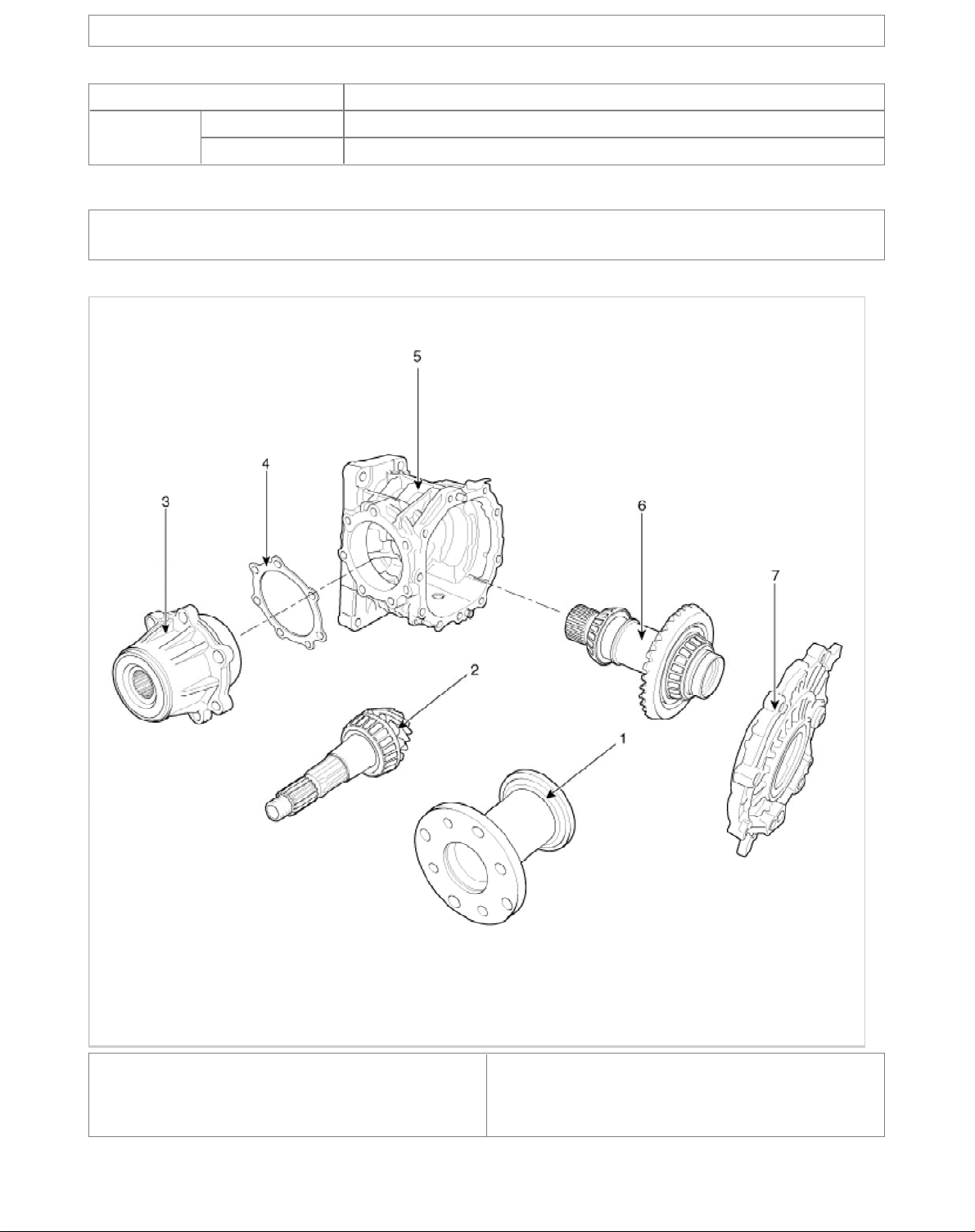
Components and Components Location
Component
1. Rear flange assembly
2. Pinion shaft
3. Pinion case
4. Spacer
5. Transfer housing
6. Hypoid gear shaft assembly
7. Transfer cover
Page 3
4 Wheel Drive (4WD) System > Transfer Assembly > Front Wheel Transfer Assembly > Repair
l
procedures
Inspection
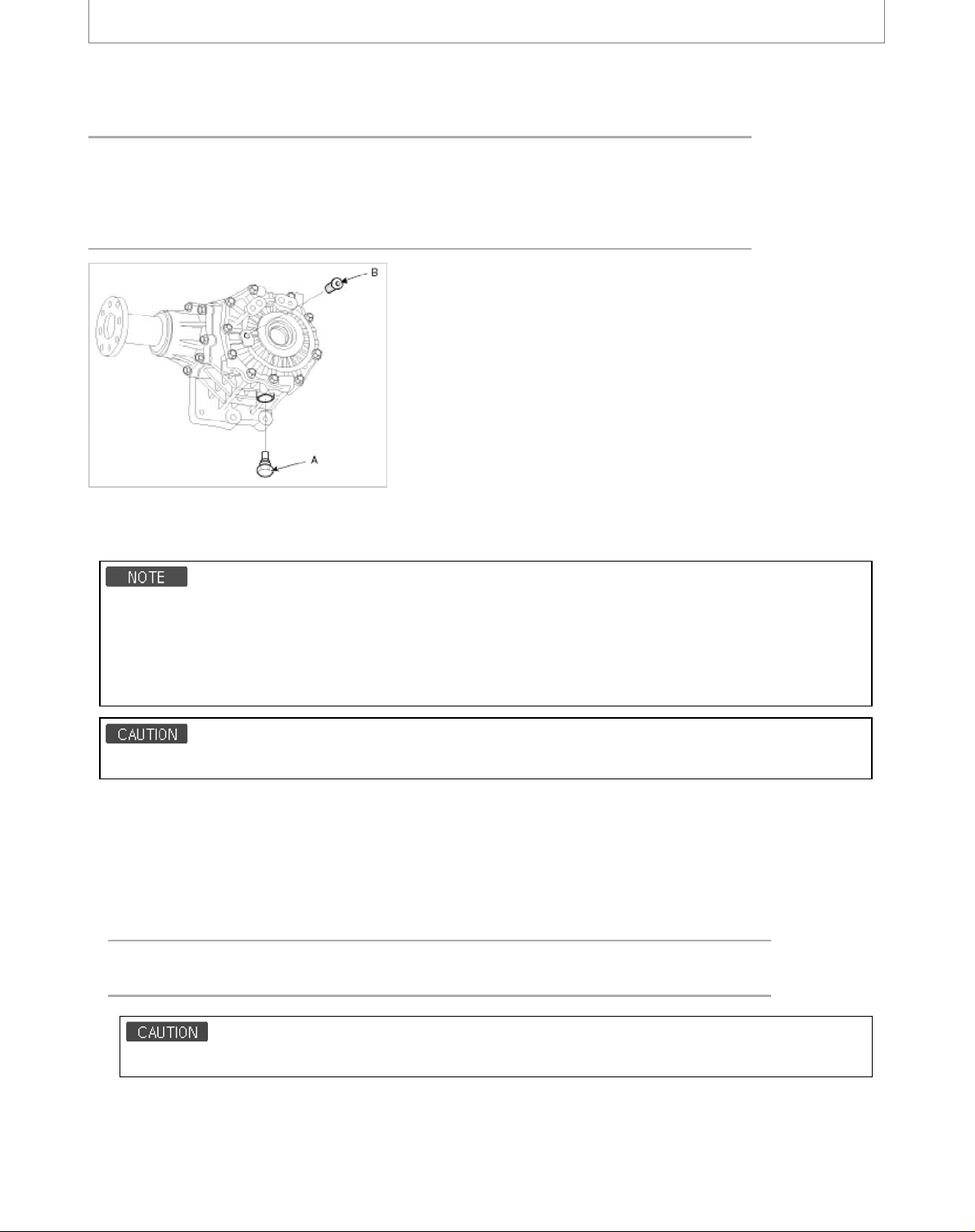
Transfer Oil Inspection
Transfer oil should be inspected and refilled every 30 months or 37,500 miles.
Tightening torque
Oil drain pulg(A) :
39.2~58.8N.m (4.0~6.0kgf.m, 28.9~43.4lb-ft)
Filler pulg(B) :
39.2~58.8N.m (4.0~6.0kgf.m, 28.9~43.4lb-ft)
Transfer Oil Replacement
1. Transfer oil is not replaced in normal condition.But it shoud be replaced every 75,000 miles in severe driving conditions.
Severe driving conditions
1. Driving in dusty, rough roads
2. Drivng in mountains areas
3. Driving for patrol car, taxi, commercial car or vehicle towing
4. Driving over 170Km/h
Transfer oil should be replaced if the transfer assembly is fall into the water.
Remova
1. Disconnect the (-) terminal from the battery.
2. Lift up the vehicle.
3. Remove the front muffler
4. Remove the propeller shaft bolts.(A-4ea)
Tightening torque :
49.0~68.6N.m (5.0~7.0kgf.m, 36.2~50.6lb-ft)
Install the propeller shaft to be near runout marking (Transfer assembly 1ea, Propeller shaft 1ea) each other.
Page 4
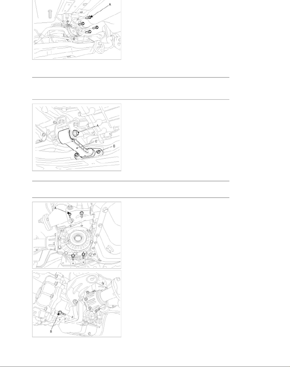
5. Remove the right driveshaft (passanger side) from the transfer case. (Refer to "Drive shaft" in DS group)
6. Remove the roll lod bracket(C) after removing bolt(A,B).
Tightening torque :
(A) 107.9~127.5N.m (11~13kgf.m, 79.6~94.1lb-ft)
(B) 49.0~63.7N.m (5.0~6.5kgf.m, 36.2~47.0lb-ft)
7. Remove the transfer case up and down mounting bolt (A-4ea, B-1ea).
Tightening torque :
(A, B) 60.8~65.7N.m (6.2~6.7kgf.m, 44.8~48.5lb-ft)
8. Remove the transfer case with the lever after supporting the transfer case with a jack.
Page 5
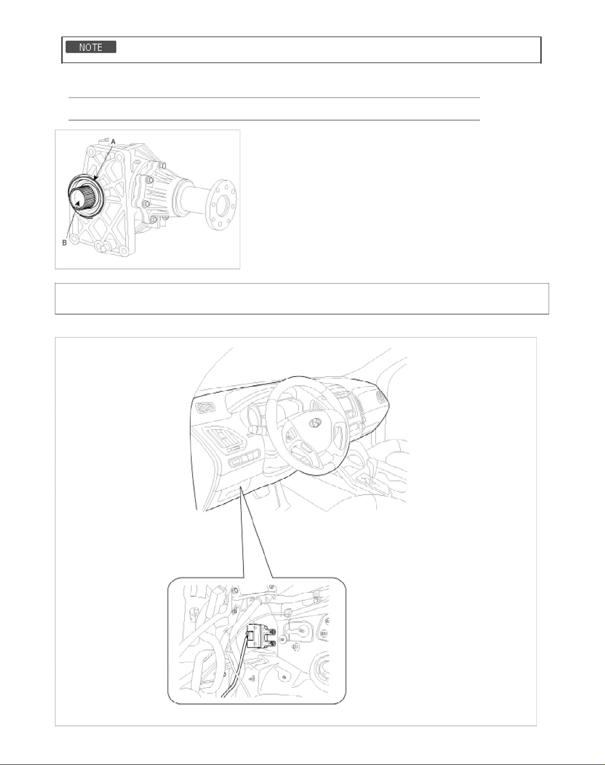
Installation
1. Installation is the reverse of removal.
• Be careful not to damage the O-ring (A). If the O-ring take damage, replace new one.
• Smear involute splines (B) all covering with molybdenum type high pressure grease.
TECHLUBE MEGAMAX - ALPHA OR EQUIVALENT
4 Wheel Drive (4WD) System > 4WD Control System > 4WD ECU > Components and
Components Location
Components Location
Page 6
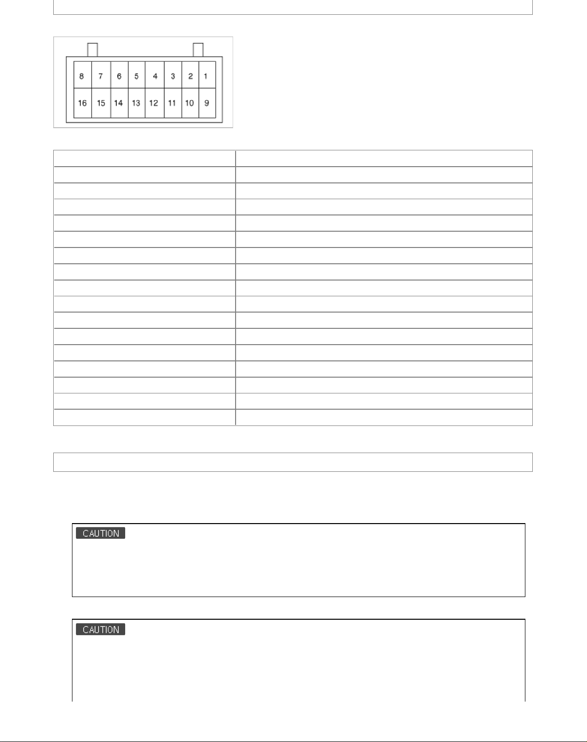
4 Wheel Drive (4WD) System > 4WD Control System > 4WD ECU > Schematic Diagrams
r
1. 4WD ECU Harness connecto
2. 4WD ECU Terminal Function
Pin No. Description
1NC
2NC
3NC
4CAN HIGH
5IG
6 BATTERY
7NC
84WD SOL +
9 LOCK MODE SW
10 NC
11 NC
12 CAN LOW
13 NC
14 NC
15 GROUND
16 4WD SOL -
4 Wheel Drive (4WD) System > 4WD Control System > 4WD ECU > Description and Operation
Description
Four Wheel Drive (4WD) transfer mode selection
1. AUTO MODE:
- When driving in 4WD AUTO mode, the vehicle operates similar to conventional 2WD vehicles under normal
operating conditions. However, if the system determines that there is a need for the 4WD mode, the engine’s
driving power is distributedto all four wheels automatically without driver intervention.
- When driving on normal roads and pavement, the vehicle moves similar to conventional 2WD vehicles.
2. LOCK MODE:
- This mode is used for climbing or descending sharp grades, off-road driving, driving on sandy and muddy roads,
etc., to maximize traction.
- This mode automatically begins to deactivate at speeds above 30 km/h (19 mph) and is shifted to 4WD AUTO
mode at speed above 40 km/h (25 mph). If the vehicle speed decelerates to below 30 km/h (19 mph), however,
Page 7
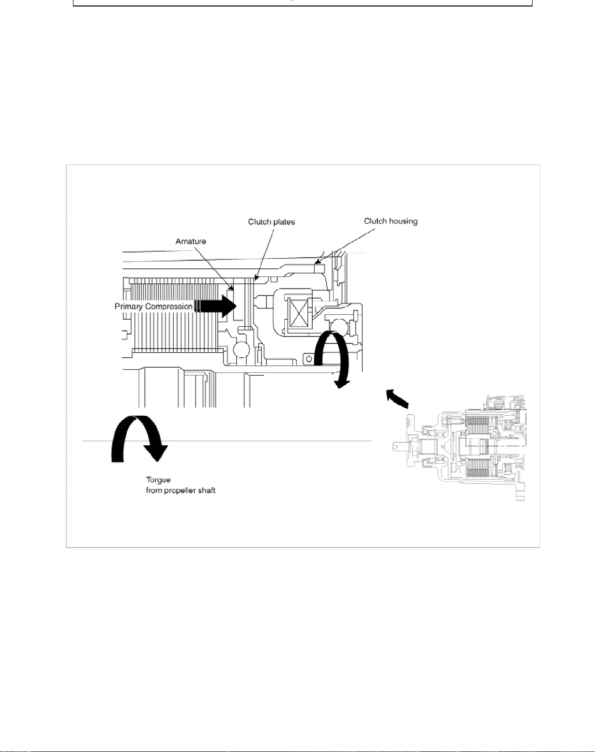
Operation
• Normal driving situation: 2WD base driving
• 4WD driving in driving situations (rapid activation, cornering etc.)
1. Input the information from each sensor in vehicle
A. Input torque (Throttle position sensor)
B. Cornering situation (Steering angle sensor)
C. Vehicle speed and different wheel speed front &rear (Wheel speed sensor)
D. Braking situation (Brake signal and ABS signal)
2. Distributed the required driving force after 4WD ECU operates.
3. EMC (Electric Magnetic Clutch) operates the primary clutch.
4. Control the cam's opening gap by operation of primary clutch.
Page 8
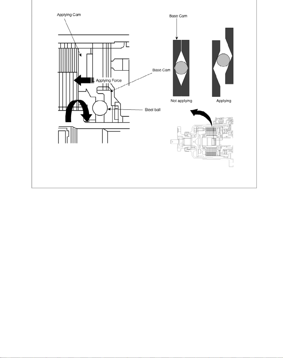
5. Control the slip of inner & outer plate.
Control variably the driving force distribution to optimize front & rear driving force.
Page 9
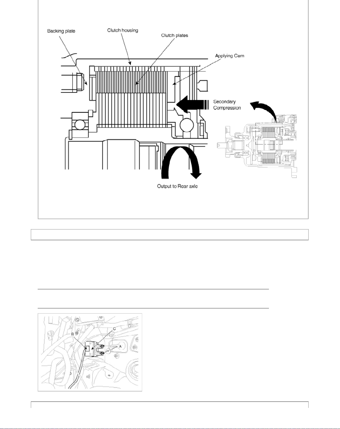
4 Wheel Drive (4WD) System > 4WD Control System > 4WD ECU > Repair procedures
p
lacement
Re
1. Remove the lower panel. (Refer to "Crash Pad" in BD group)
2. Remove the IPM.(Refer to "Fuses and Relays" in BE group)
3. Remove the parking brake pedal.(Refer to "Parking Brake System" in BR group)
4. Remove the 4WD ECU(C) after removing the nut (A-2ea) and the connector (B).
Tightening torque:
9.8 ~ 11.8 N.m (1.0 ~ 1.2 kgf.m, 7.2 ~ 8.7 lb-ft)
Page 10
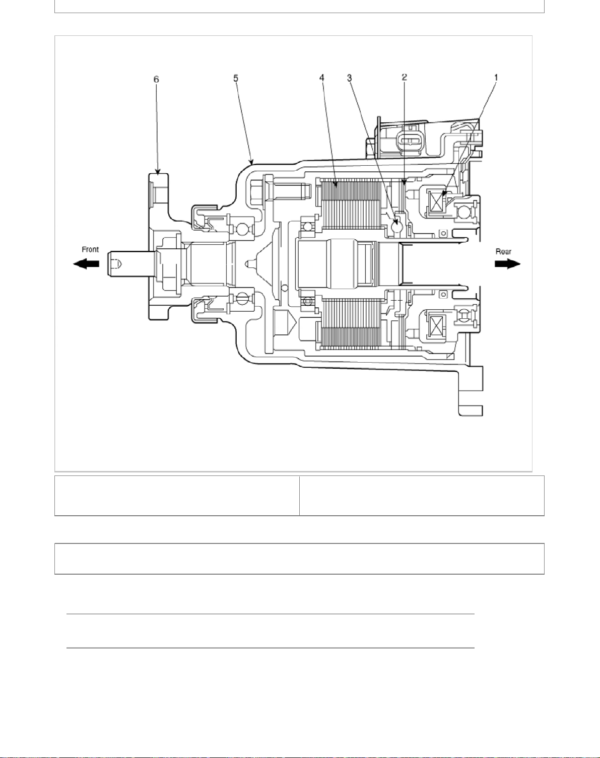
(ITCC) > Components and Components Location
s
l
Component
1. Magnetic Clutch
2. Pilot clutch
3. Cam
4. Main clutch
5. Housing
6. Flange
4 Wheel Drive (4WD) System > Coupling Assembly > Intelligent Torque controlled Coupling
(ITCC) > Repair procedures
Remova
1. Remove the 4WD coupling assembly bolts (A-3ea) mounted to the rear propellar shaft (B).
Tightening torque :
49.0~68.6N.m (5.0~7.0kgf.m, 36.2~50.6lb-ft)
Page 11
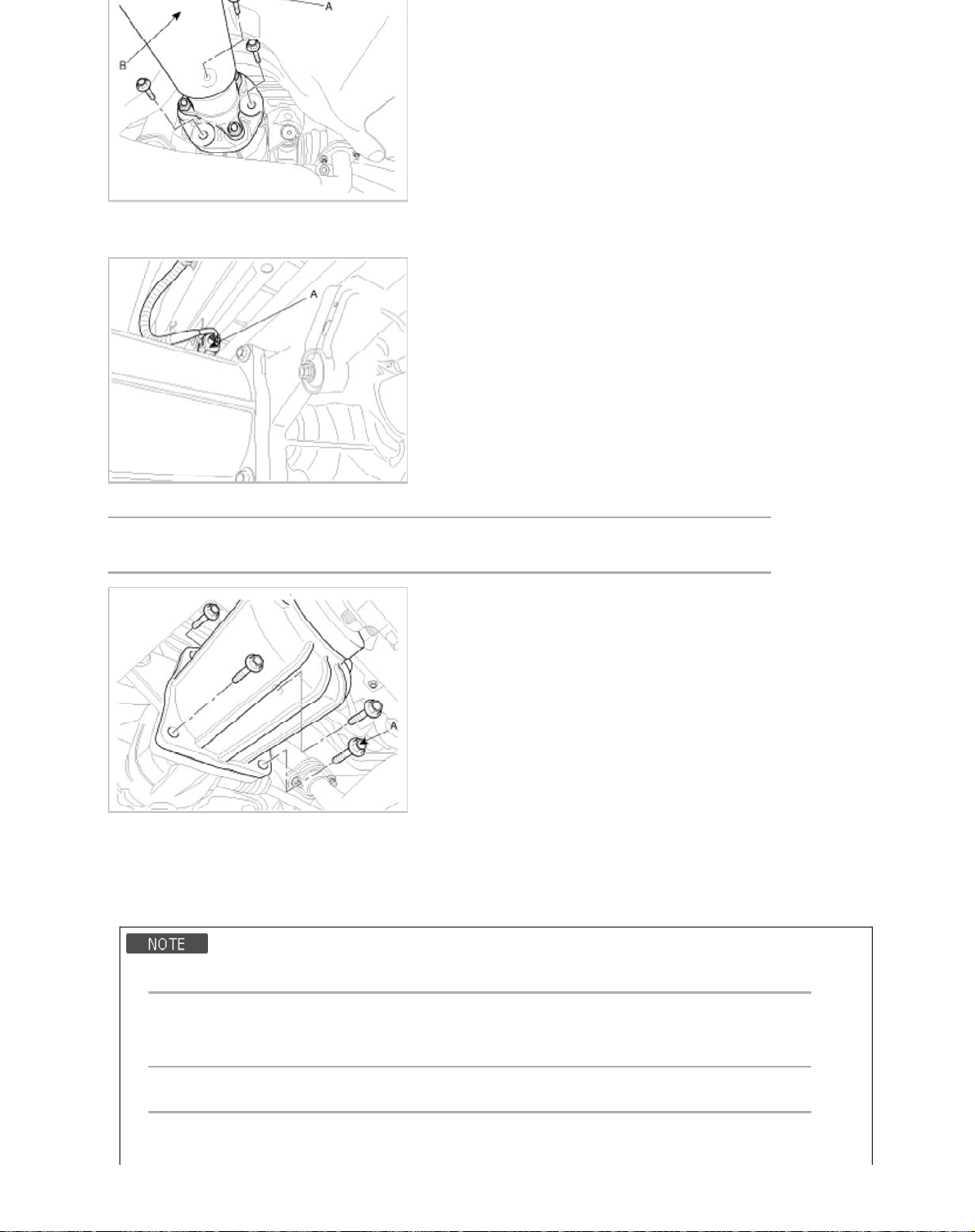
2. Using a flat tool, separate the propellar shaft from 4WD coupling assembly.
:
E
3. Remove the electric magnetic clutch connector(A).
4. Remove the 4WD coupling assembly mounting bolts (A-4ea).
Tightening torque :
58.8~63.7N.m (6.0~6.5kgf.m, 43.4~47.0lb-ft)
5. Using a flat tool, separate the 4WD coupling assembly from the rear differential carrier assembly.
Installation
1. Installation is the reverse of removal.
• Grease the drive gear of the differential carrier assembly.
High pressure grease
KLUBER MICROLUBE GNY 202 or equivalent
GREAS
• Spread sealant on the matching face of coupling & differential carrier.
Sealant material
FIPG(Formed in Place Gaskets)-B (MS721-40) or equivalent to LT5702
-TRANSMISSION (MS511-55, TMG-2)
Page 12
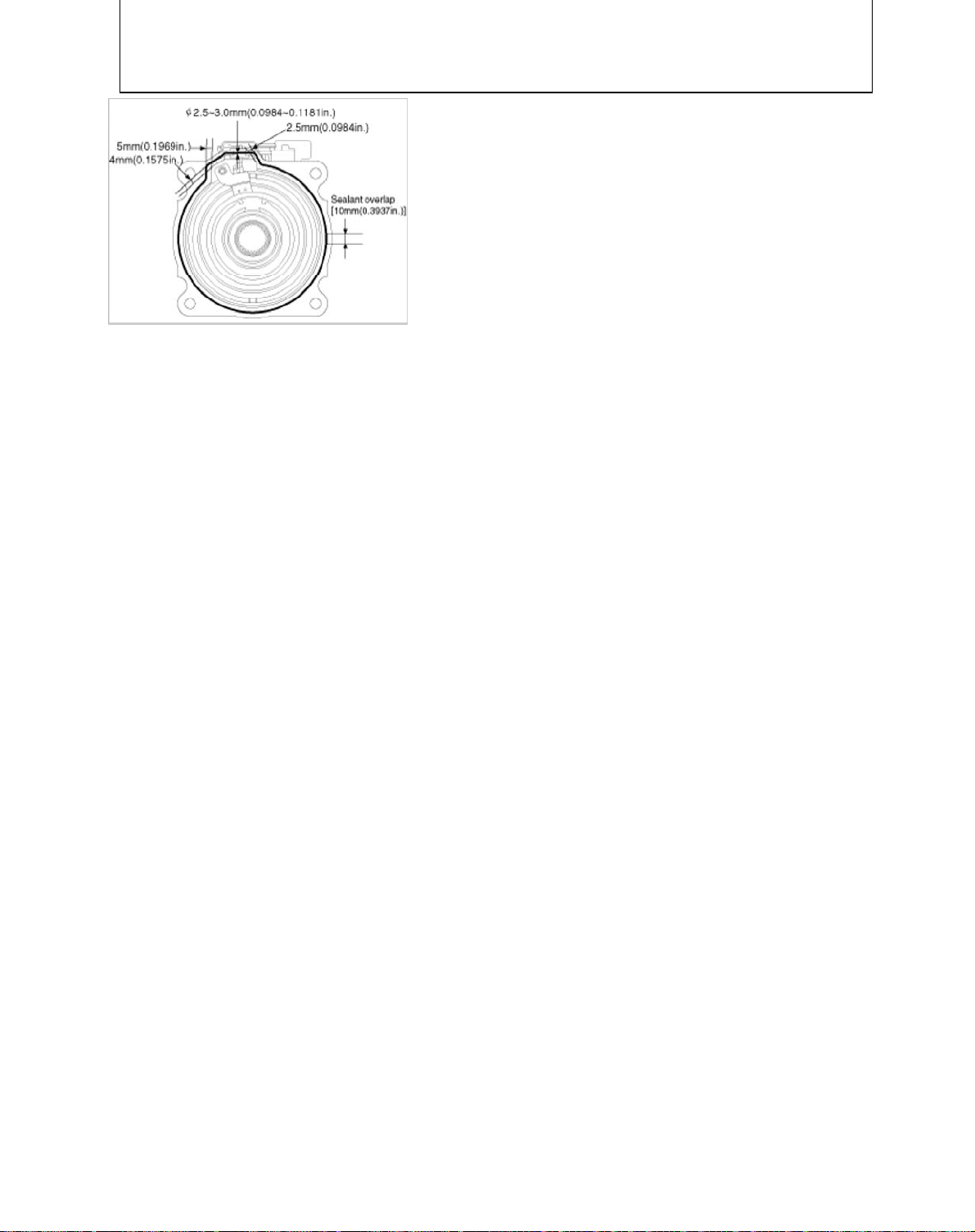
• Remove oil on the matching face before spread sealant.
• Refer to instruction drawing for spreading line.
• Staring point anding point should be overlapped (min.10mm(0.3937in.))
• Be sure to assemble part "Coupling & Differential carrier" within 3 minutes after spread sealant.
Page 13

m
Automatic Transaxle System > General Information > Specifications
p
s
s
6
ecification
S
Item Specification
Transmission type A6MF1
Engine model Gasoline 2.0 Gasoline 2.4
Torque converter type 3-element, 1-stage, 2-phase type
Torque converter size Ø236 mm (9.2913 in.)
Oil pump system Parachoid
Clutch: 2EA
Friction elements
Planetary gear 3EA
1st 4.162 4.212
2nd 2.575 2.637
3rd 1.772 1.800
Gear ratio
Final gear ratio 3.648 3.195
Fluid pressure balance piston 3EA
Accumulator 4EA
Solenoid valve 8EA (VFS:6EA, ON/OFF:2EA)
Shift lever position 4 Range (P,R,N,D)
Oil filter 1EA
4th 1.369 1.386
5th 1.000 1.000
6th 0.778 0.772
Reverse 3.500 3.385
Brake: 3EA
OWC : 1EA
VFS: Variable Force Solenoid
Tightening Torque
Item N.m Kgf.m lb-ft
TCM installation mounting bolt 7.8 ~ 11.8 0.8 ~ 1.2 5.8 ~ 8.7
Shift cable bracket mounting bolt 14.7 ~ 21.6 1.5 ~ 2.2 10.9 ~ 15.9
Input shaft speed sensor mounting bolt 9.8 ~ 11.8 1.0 ~ 1.2 7.2 ~ 8.7
Output shaft speed sensor mounting bolt 9.8 ~ 11.8 1.0 ~ 1.2 7.2 ~ 8.7
Shift lever assembly bolt 8.8 ~ 13.7 0.9 ~ 1.4 6.5 ~ 10.1
Inhibitor switch mounting bolt 9.8 ~ 11.8 1.0 ~ 1.2 7.2 ~ 8.7
Valve body cover mounting bolt 9.8 ~ 11.8 1.0 ~ 1.2 7.2 ~ 8.7
Eyebolt 34.3 ~ 44.1 3.5 ~ 4.5 25.3 ~ 32.6
Oil drain plug 34.3 ~ 44.1 3.5 ~ 4.5 25.3 ~ 32.6
Oil level plug 34.3 ~ 44.1 3.5 ~ 4.5 25.3 ~ 32.6
Torque converter mounting bolt 45.1 ~ 52.0 4.6 ~ 5.3 33.3 ~ 38.3
Automatic transaxle upper mounting bolt 42.2 ~ 53.9 4.3 ~ 5.5 31.3 ~ 39.8
Page 14
Automatic transaxle support bracket bolt 88.3 ~107.9 9.0~11.0 65.1 ~ 79.8
s
s
6
Lubricant
Item Specified lubricant Quantity
SK ATF SP-Ⅳ, MICHANG ATF SP-Ⅳ, NOCA ATF SP-
Transaxle fluid
Ⅳ, Hyundai Genuine ATF SP-Ⅳ
or other brands meeting the above specification
approved by Hyundai Motors Corp.
7.1L (1.88 U.S gal., 7.50 U.S.qt.,
6.24 Imp.qt.)
Sealant
Item Specified sealant
Rear cover
Torque converter housing
Valve body cover
LOCTITE FMD-546 or THREE-BOND TB1281B
Automatic Transaxle System > General Information > Special Service Tools
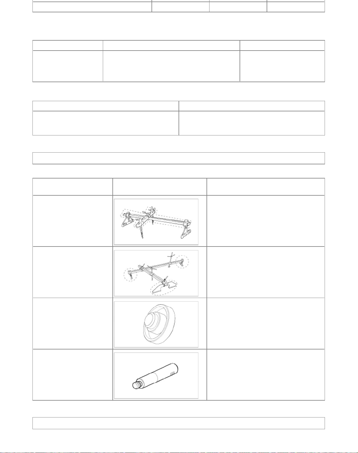
Special Service Tool
Tools
(Number and name)
09200-38001
Engine support fixture
(Beam)
09200-2S000
Engine support fixture
(Supporter)
09453-3L241
Oil seal installer
09231-H1100
Bar
Illustration Use
Removal and installation of the transaxle.
Except lower supporter, use beam only with
new engine support fixture supporter(SST
No.:09200-2S000)
Removal and installation of the transaxle.
Use this supporter with the upper beam of the
engine support fixture(SST No.:09200-38001)
Installation of transaxle case oil seal.
[Using with handle (SST No.:09231-H1100)]
Installation of transaxle case oil seal.
[Using with oil seal installer (SST No.:094533L241)]
Automatic Transaxle System > Automatic Transaxle System > Repair procedures
Page 15
Oil level Check
b
6
A check of ATF level is not normally required during scheduled services. If an oil leak is found, perform the oil level
check procedure after repairs are completed.
When checking the oil level, be careful not to enter dust, foreign matters, etc. from fill hole.
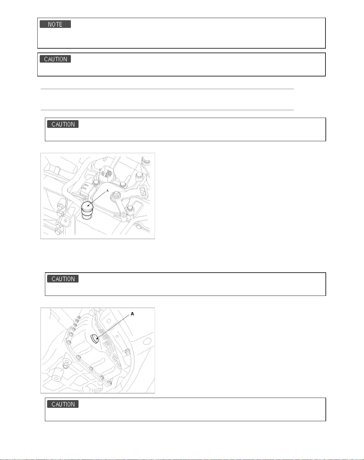
1. Remove the eyebolt (A).
Eyebolt tightening torque:
34.3~44.1 N.m (3.5~4.5 kgf.m, 25.3~32.6 l
The gasket of the eyebolt use new one.
2. Add ATF SP-IV 700cc to the ATF injection hole.
-ft)
3. Start the engine. (Don’t step on brake and accelerator simultaneously.
4. Confirm that the temperature of the A/T oil temperature sensor is 50~60°C(122~140°F) with the GDS.
5. Shift the select lever slowly from “P” to “D”, then “D” to “P” and repeat one more at idle.
Keep on each speed position more than 2 sec.
6. Lift the vehicle, then remove the oil level plug (A) from the valve body cover.
At this time, the vehicle must be a horizontal state.
7. If the oil flows out of the overflow plug in thin steady stream, the oil level is correct.
Page 16
Oil level check (excess or shortage) method
b
b
6
• Excess: Oil flows out in thick stream.
• Shortage: No oil flows out of the overflow plug.
If there is no damage at the automatic transaxle and the oil cooler, the oil cooler hose, transaxle case, valve body
tightening state are normal, ATF must drop out after performing above 1 to 7 procedures. After performing above 1
to 7 procedures, if the oil doesn’t drop out, inspect the automatic transaxle assembly.
The gasket of the oil level plug use new one.
Oil level plug tightening torque:
34.3 ~ 44.1 N.m (3.5 ~ 4.5 kgf.m, 25.3 ~32.6 l
8. Put down the vehicle with the lift and then tighten the eyebolt.
-ft)
Replacement
ATF of 6 speed automatic transaxle doesn’t be replaced. But, if the vehicle is severe use or business use, replace
ATF every 60,000 miles for severe usage.
Severe usage is defined as
• Driving in rough road (Bumpy, Gravel, Snowy, Unpaved road, etc)
• Driving in mountain road, ascent/descent
• Repetition of short distance driving
• More than 50% operation in heavy city traffic during hot weather above 32°C(89.6°F) .
• Police, Taxi, Commercial type operation or trailer towing, etc
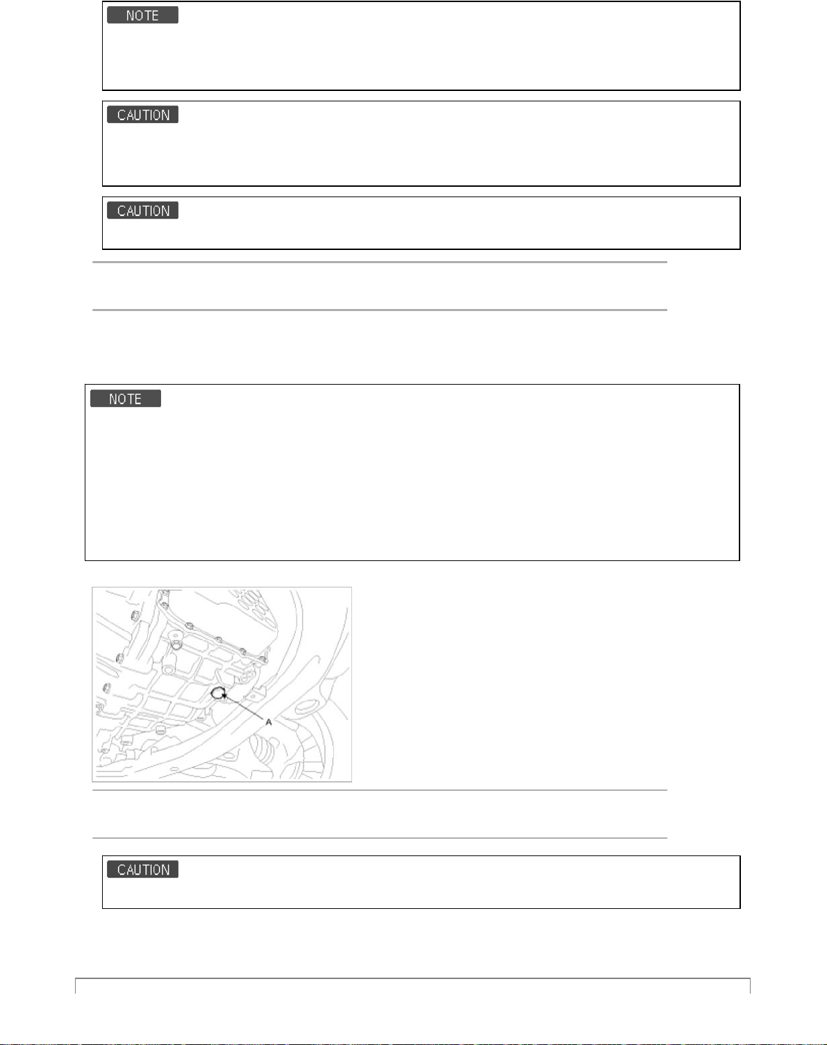
1. Remove the drain plug (A) and reinstall the drain plug after draining ATF totally.
Drain plug tightening torque:
34.3 ~ 44.1 N.m (3.5 ~ 4.5 kgf.m, 25.3 ~32.6 l
The gasket of the drain plug use new one.
2. Fill the oil about 5 liters.
3. Check the oil level. (Refer to Oil level check procedure.)
-ft)
Page 17
Components and Components Location
)
)
6
Components (1
Components (2
Page 18
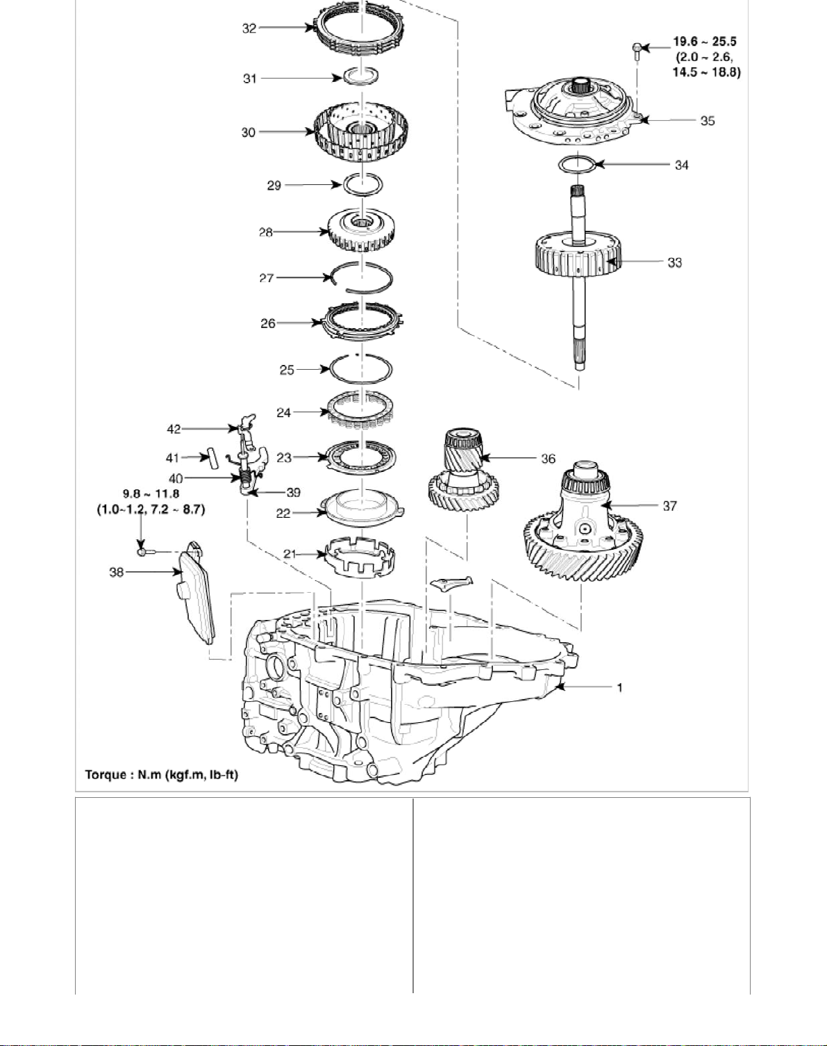
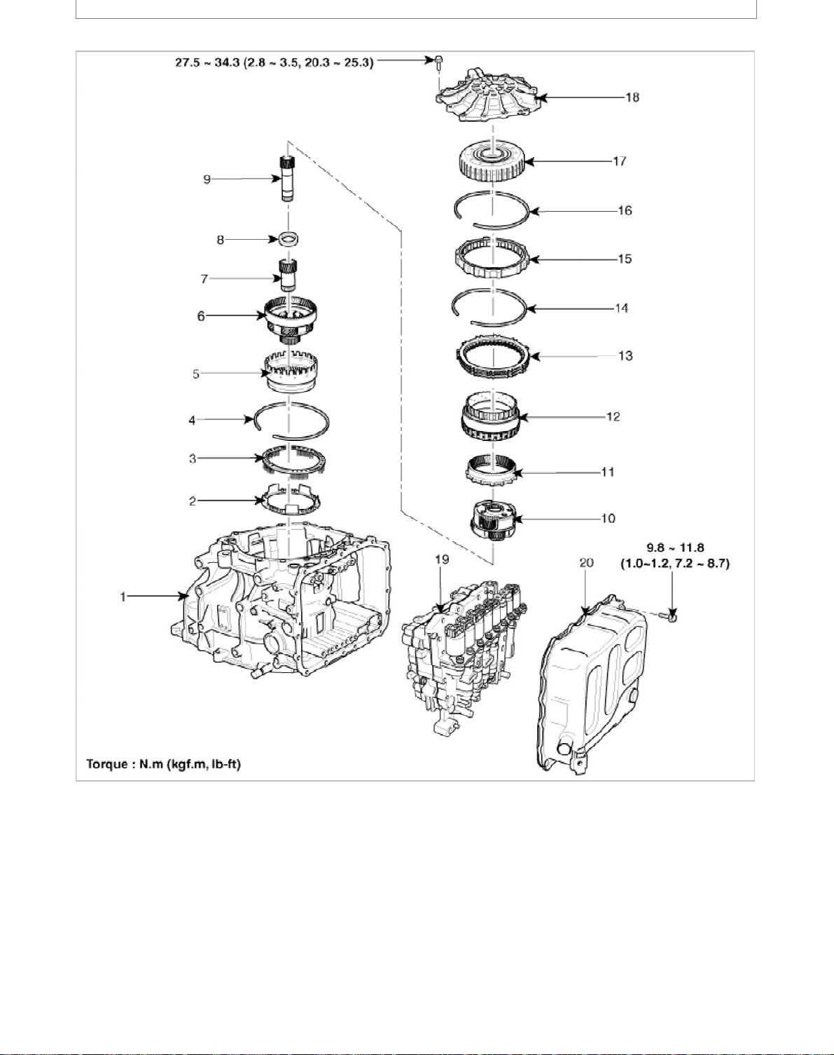
1. Automatic transaxle case
6
2. Low & reverse brake piston
3. Low & reverse brake return spring
4. Snap ring
5. Front annulus gear assembly
6. Front planetary gear assembly
7. Front sun gear assembly
8. Bearing
9. Middle sun gear assembly
10. Middle & rear planetary gear assembly
11. Rear annulus gear assembly
22. Under drive brake chamber
23. Under drive brake piston
24. Under drive brake spring
25. Snap ring
26. Under drive brake disc set
27. Snap ring
28. Under drive brake hub assembly
29. Thrust washer
30. 35R & 2/6 hub assembly
31. Thrust bearing
32. 2/6 brake disc set
Page 19
13. Low & reverse brake disc set
n
6
14. Snap ring
15. One way clutch assembly
16. Snap ring
17. Overdrive clutch assembly
18. Rear cover assembly
19. Valve body assembly
20. Valve body cover
21.Under drive brake retainer
Components Locatio
34. Thrust washer
35. Oil pump assembly
36. Transfer driven gear assembly
37. Differential assembly
38. Oil filter assembly
39. Parking sprag
40. Parking sprag shaft & spring
41. Support shaft
42. Parking load guide
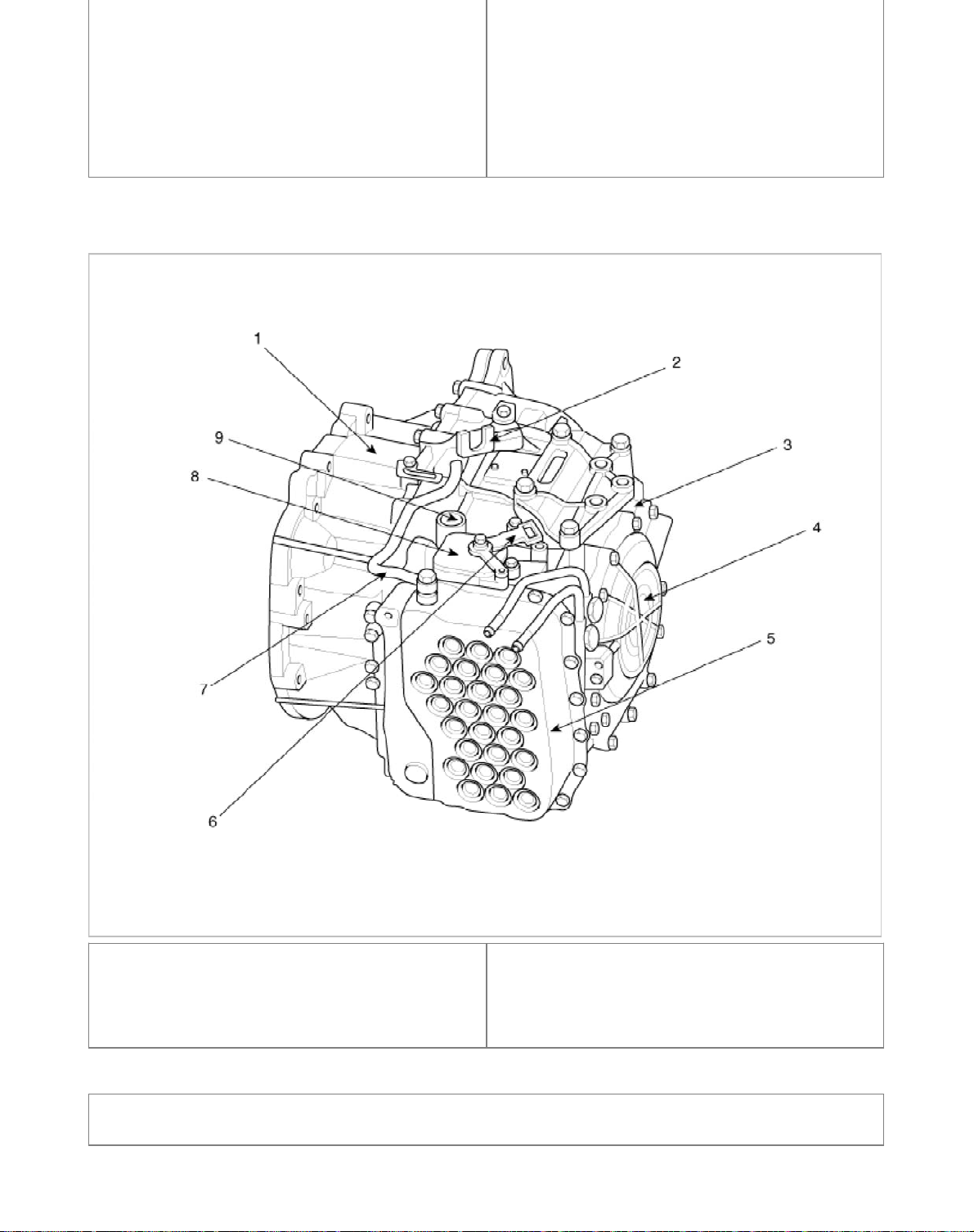
1. Converter housing
2. Shift cable bracket
3. Automatic transaxle case
4. Rear cover
5. Valve body cover
6. Manual control lever
7. Air breather hose
8. Inhibitor switch
9. Solenoid valve connector
Automatic Transaxle System > Automatic Transaxle System > Automatic Transaxle >
Repair procedures
Page 20
l
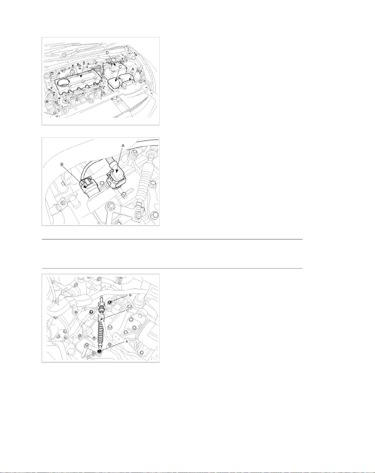
1. Remove the following items;
T
b
b
6
A. Air duct (A) and engine cover (B). (Refer to "Intake and Exhaust system" in EM group.)
B. Air cleaner assembly (C). (Refer to "Intake and Exhaust system" in EM group.)
C. Battery and battery tray (D). (Refer to "Charging system" in EE group.)
2. Dissconnect the solenoid valve connector (A) and inhibitor switch connector (B).
3. Remove the shift cable (C) after removing the nut (A) and the bolt (B).
ightening torque:
(A) 7.8 ~ 11.8 N.m (0.8 ~ 1.2 kgf.m, 5.8 ~ 8.7 l
(B) 14.7 ~21.6 N.m(1.5 ~2.2 kgf.m, 10.9 ~15.9 l
4. Remove the ground line after removing the bolt (A).
-ft)
-ft)
Page 21
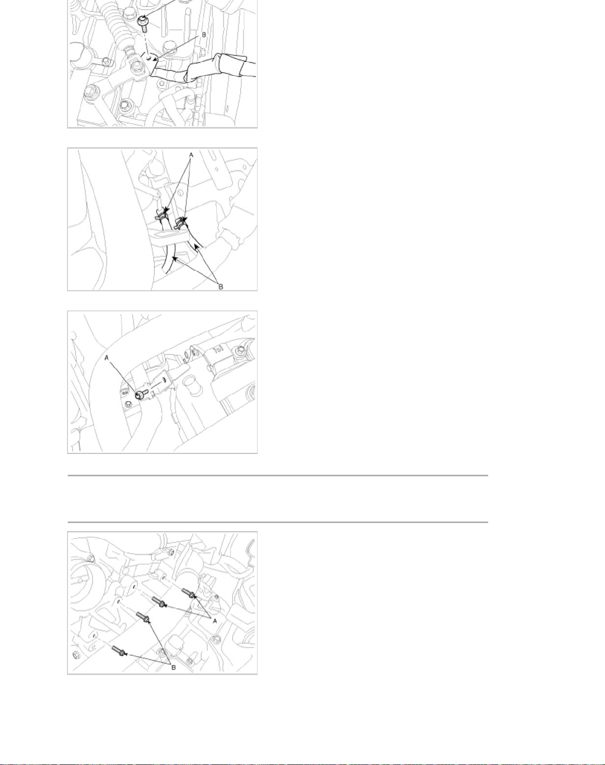
5. Disconnect the hose (B) after removing the automatic transaxle fluid cooler hose clamp (A).
T
b
b
6
6. Remove the wiring bracket installation bolt (A).
7. Remove the automatic transaxle upper mounting bolt (A-2ea) and the starter motor mounting bolt (B-2ea).
ightening torque:
(A) 42.2 ~ 54.0 N.m (4.3 ~5.5 kgf.m, 31.1 ~ 39.8 l
(B) 49.0 ~ 63.7 N.m (5.0 ~6.5 kgf.m, 36.2 ~ 47.0 l
8. Remove the cowl top cover or wiper motor. (Refer to "Windshield Wiper/Washer" in BE group.)
9. Remove the cowl complete assembly panel(A).
-ft)
-ft)
Page 22
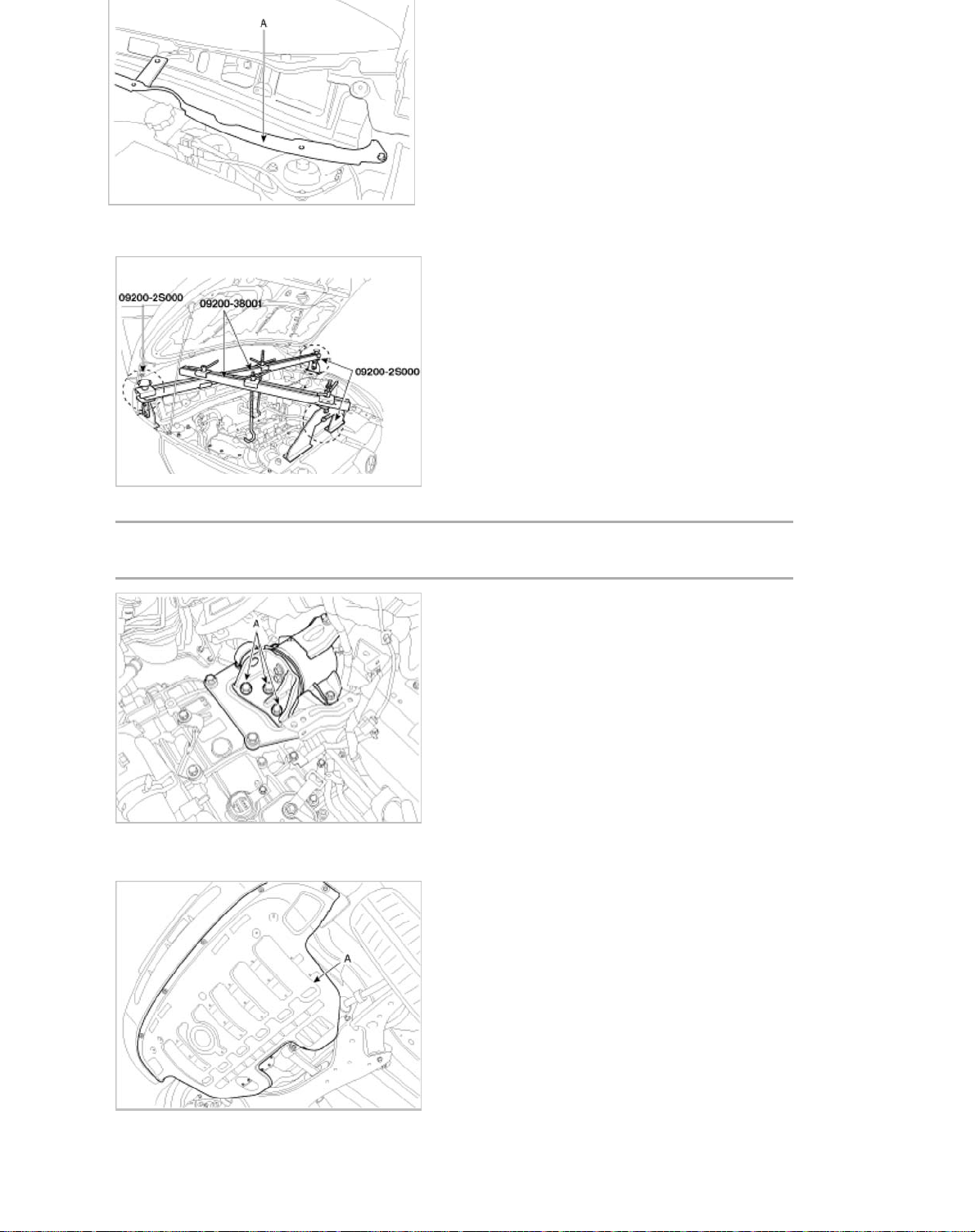
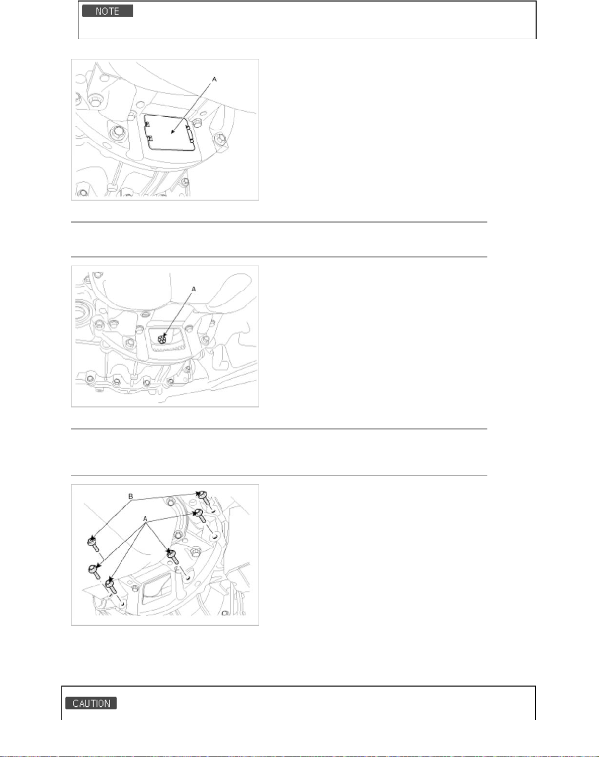
10. Using the engine support fixture (Support SST No.: 09200-2S000, Beam SST No.: 09200-38001), hold the engine and
6
transaxle assembly safely.
11. Remove the automatic transaxle mounting support bracket bolt (A).
Tightening torque:
88.3 ~ 107.9 N.m (9.0 ~ 11.0 kgf.m, 65.1 ~ 79.8 lb-ft)
12. Lift the vehicle with a jack.
13. Remove the under cover (A).
14. Remove the Sub frame assembly. (Refer to "Front suspension system" in SS group.)
15. Remove the drive shaft assembly. (Refer to "Drive shaft assembly " in DS group.)
Page 23
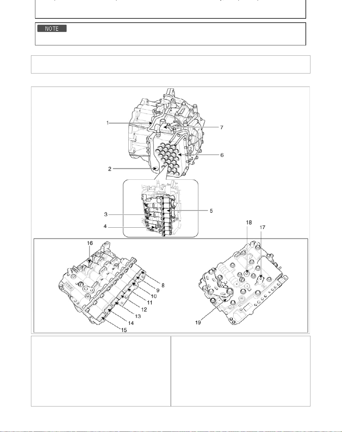
In the case of 2WD vehicle, not remove the transfer assembly.
n
6
17. Remove the dust cover(A).
18. Remove the torque converter mounting bolt (A-4ea) with rotating the crankshaft.
Tightening torque:
45.1 ~ 52.0 N.m (4.6 ~ 5.3 kgf.m, 33.3 ~ 38.3 lb-ft)
19. Remove the automatic transaxle with a jack after removing the mounting bolt (A-4ea, B-2ea).
Tightening torque:
(A) 29.4 ~ 41.2 N.m (3.0 ~ 4.2 kgf.m, 21.7 ~ 30.4 lb-ft)
(B) 42.2 ~ 54.0 N.m (4.3 ~5.5 kgf.m, 31.1 ~ 39.8 lb-ft)
Installatio
1. Installation is the reverse of removal.
Page 24
• Power steering fluid replacement and air bleeding (Refer to "General information" in ST group.)
n
2
6
• Adding automatic transaxle fluid. (Refer to "automatic transaxle system" in this group.)
• When replacing the automatic transaxle, reset the automatic transaxle's values by using the GDS.
Automatic Transaxle System > Valve Body System > Components and Components
Location
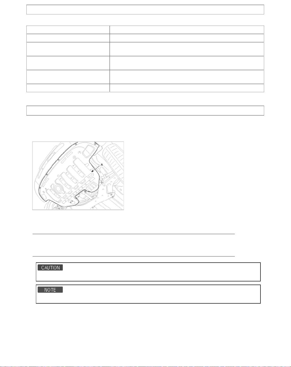
Component Locatio
1. Air breather hose
2. Oil level plug
3. Valve body assembly
4. Oil temperature sensor
5. Solenoid valve
6. Valve body cover
7. Inhibitor switch
8. T/Con (VFS N/L)
9. 35R(VFS,N/H)
10. 2/6B (VFS,N/L)
11. UD(VFS,N/H)
12. OD(VFS,N/H)
13. SS-B(ON/OFF)
14. SS-A(ON/OFF)
15. LINE pressure(VFS,N/H)
16. PCV adjust screw
17. UD/B pressure
18. LR/B pressure(Low & Reverse Brake)
19. Accumulator
Page 25
Automatic Transaxle System > Valve Body System > Valve Body > Specifications
p
n
l
T
b
b
3
6
ecificatio
S
Piece 3pcs
Spool 20ea
Control
Solenoid valve
Pressure adjusting
Terminal type Module
Line pressure (1), Reducing pressure (2), PCV (4)
Full line pressure variable control
Torque converter release control
VFS : 6ea
ON/OFF: 2ea
7ea
Automatic Transaxle System > Valve Body System > Valve Body > Repair procedures
Remova
1. Remove the battery and the battery tray. (Refer to "Charging system" in EE group.)
2. Remove the under cover (A).
3. Replace new gasket and the plug after drining the automatic transaxle fluid by removing the drain plug.
(Refer to "Automatic transaxle system" in this group.)
4. Remove the valve body cover (A) and eyebolt (B).
ightening torque:
(A) 9.8 ~ 11.8 N.m (1.0 ~ 1.2 kgf.m, 7.2 ~ 8.7 l
(B) 34.3 ~ 44.1 N.m (3.5 ~ 4.5 kgf.m, 25.3 ~ 32.6 l
The gasket of the eyebolt use new one.
Remove installation bolts in the engin room first and then remove others under the vehicle.
-ft)
-ft)
Page 26
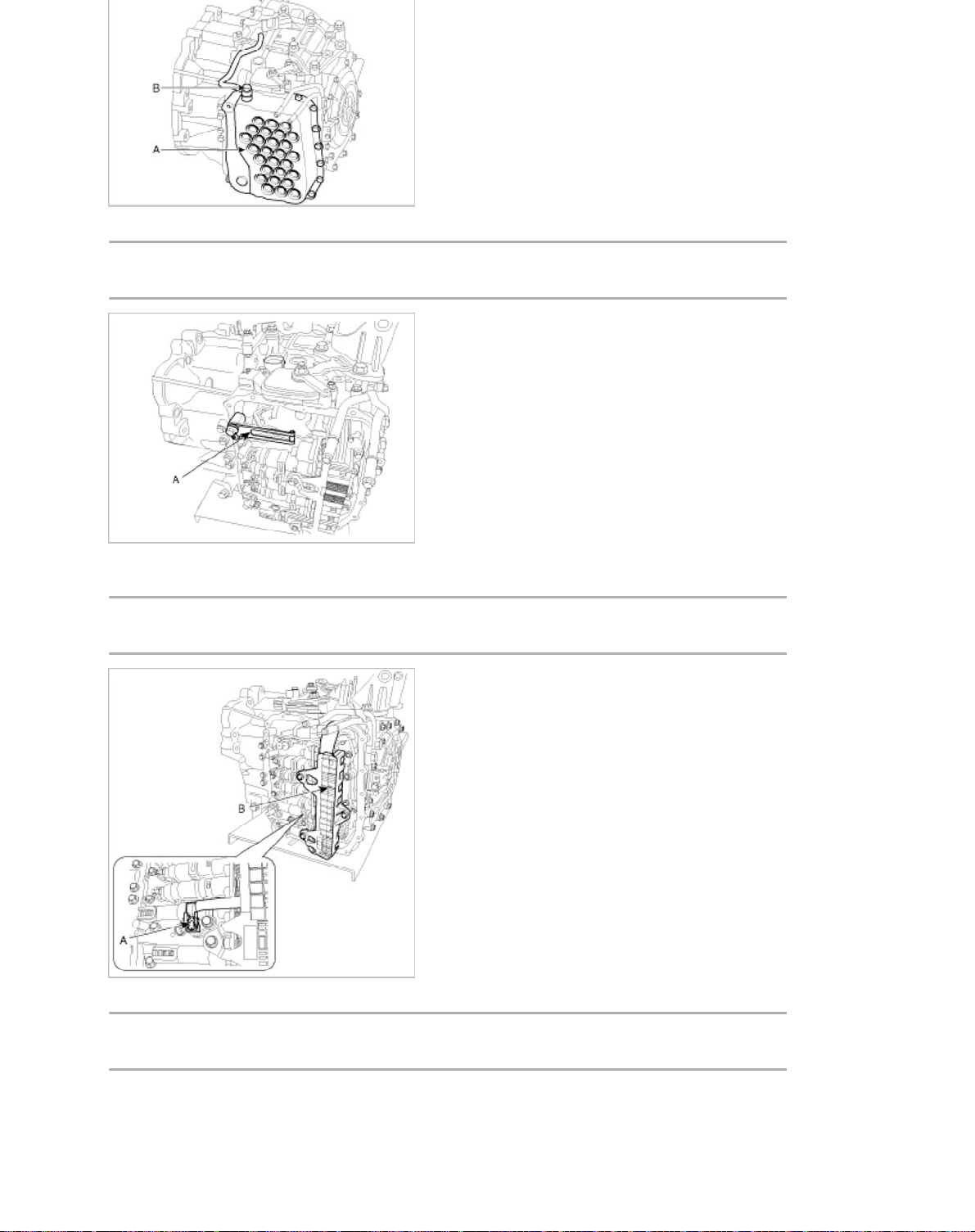
5. Remove the plate and the detend spring (A) after removing the bolt.
T
2
T
b
T
b
4
6
ightening torque:
4.5 ~ 35.3 N.m (2.5 ~ 3.6 kgf.m, 18.1 ~ 26.0 lb-ft)
6. Remove the bolt (3ea) after disconnecting the solenoid valve (B) connector and the oil temperature sensor connector
(A).
ightening torque:
9.8 ~ 11.8 N.m (1.0 ~ 1.2 kgf.m, 7.2 ~ 8.7 l
-ft)
7. Remove the valve body assembly (A).
ightening torque:
9.8 ~ 11.8 N.m (1.0 ~ 1.2 kgf.m, 7.2 ~ 8.7 l
-ft)
Page 27
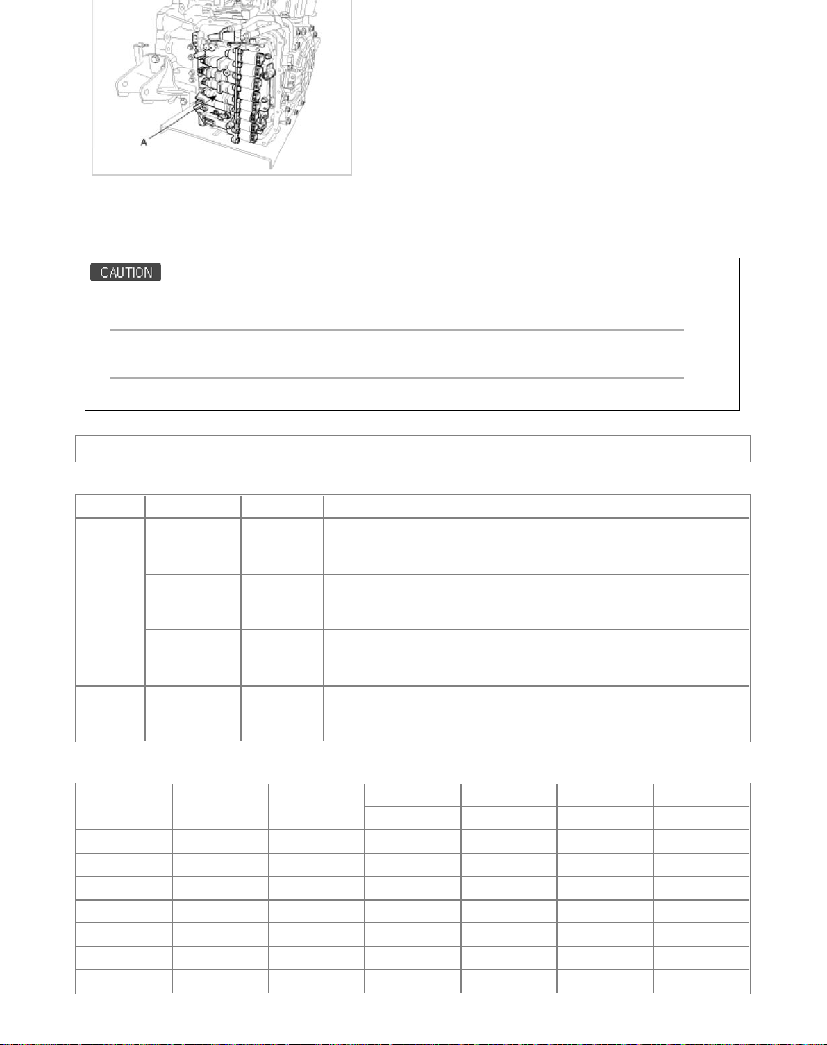
Installatio
n
n
5
6
1. Installation is the reverse of removal.
After replacement or reinstallation procedure of the valve body assembly, must perform procedures below.
• Continue to apply liquid gasket at application points at the valve body cover with Ø2.5mm (0.0984in.) thickness.
Liquid gasket Part name :
Threebond 1281B or LOCTITE FMD-546
• Adding automatic transaxle fluid. (Refer to "automatic transaxle system" in this group.)
Automatic Transaxle System > Valve Body System > Solenoid valve > Specifications
Specificatio
Item Function Piece Specification
Control pressure: 9.81~500.14kpa (0.1~5.1kgf/cm², 1.42~72.54 psi)
Current value: 50~850mA
Low Type, 5.1Ω
Control pressure: 500.14~9.81kpa (5.1~0.1kgf/cm², 72.54~1.42psi)
Current value: 50~850mA
High Type, 5.1Ω
Control pressure: 500.14~9.81kpa (5.1~0.1kgf/cm², 72.54~1.42psi)
Current value: 50~850mA
High Type, 5.1Ω
Control pressure: 490.33kpa (5.0kgf/cm², 71.12psi)
10~11Ω
Low Type
VFS
On/Off
26/B
T/Con
Line pressure
control
35R
UD
OD
SS-A
SS-B
2
1
3
2
Solenoid Valve Operation Table
SS-A SS-B
N, P ●●●
1 ΔΔ●
2 ●●●
3 ●●
4 ●
5 ●●
UD-VFS OD-VFS 35R-VFS 26-VFS
N/H N/H N/H N/L
Page 28
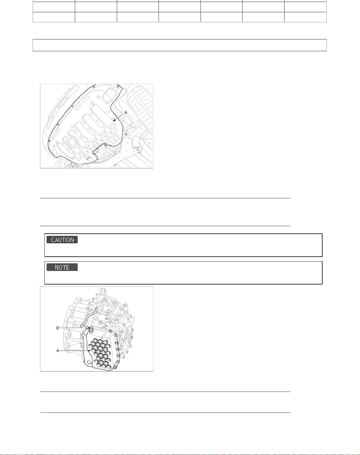
L ●●
l
T
b
b
T
b
6
6
R ●●●
Automatic Transaxle System > Valve Body System > Solenoid valve > Repair procedures
Remova
1. Remove the battery and the battery tray. (Refer to "Charging system" in EE group.)
2. Remove the under cover (A).
3. Replace new gasket and the plug after drining the automatic transaxle fluid by removing the drain plug.
(Refer to "Automatic transaxle system" in this group.)
4. Remove the valve cover (A) and eyebolt (B).
ightening torque:
(A) 9.8 ~ 11.8 N.m (1.0 ~ 1.2 kgf.m, 7.2 ~ 8.7 l
(B) 34.3 ~ 44.1 N.m (3.5 ~ 4.5 kgf.m, 25.3 ~ 32.6 l
The gasket of the eyebolt use new one.
Remove installation bolts in the engin room first and then remove others under the vehicle.
5. Remove the bolt (3ea) after disconnecting the solenoid valve connector (B) and the oil temperature sensor connector
(A).
-ft)
-ft)
ightening torque:
9.8 ~ 11.8 N.m (1.0 ~ 1.2 kgf.m, 7.2 ~ 8.7 l
-ft)
Page 29
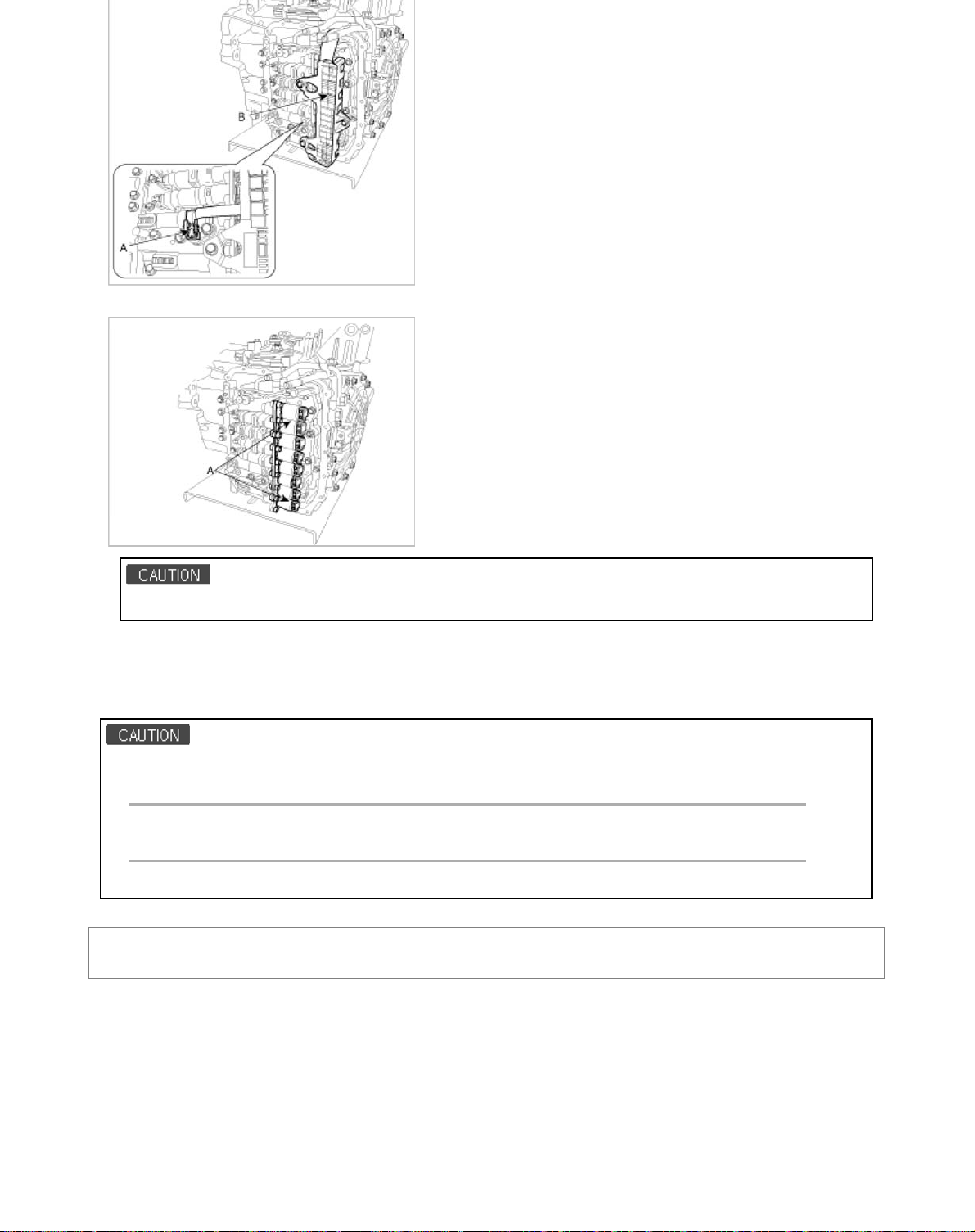
6. Remove the solenoid valve (A) after removing the solenoid support.
n
n
7
6
When installing, apply the ATF oil or White Vaseline to the O-ring not to be damaged.
Installatio
1. Installation is the reverse of removal.
After replacement or reinstallation procedure of the valve body assembly, must perform procedures below.
• Continue to apply liquid gasket at application points at the valve body cover with Ø2.5mm (0.0984in.) thickness.
Liquid gasket Part name :
Threebond 1281B or LOCTITE FMD-546
• Adding automaticmatic transaxle fluid. (Refer to "automaticmatic transaxle system" in this group.)
Automatic Transaxle System > Automatic Transaxle Control System > Components and
Components Location
Components Locatio
Page 30
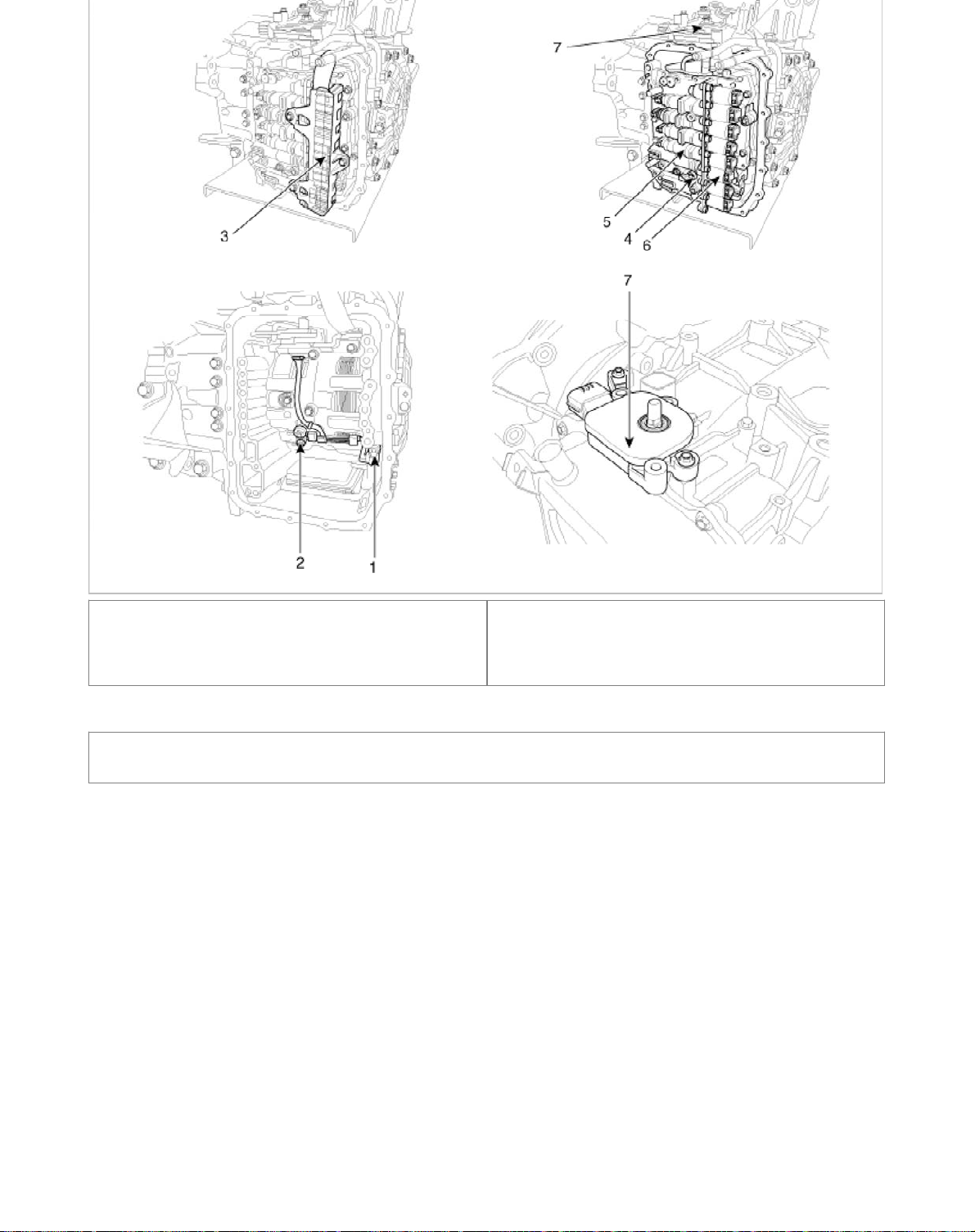
1. Input speed sensor
s
6
2. Output speed sensor
3. Solenoid valve connector
4. Oil temperature sensor
5. Valve body assembly
6. Solenoid valve
7. Inhibitor switch
Automatic Transaxle System > Automatic Transaxle Control System > Shift Lever >
Components and Components Location
Component
Page 31
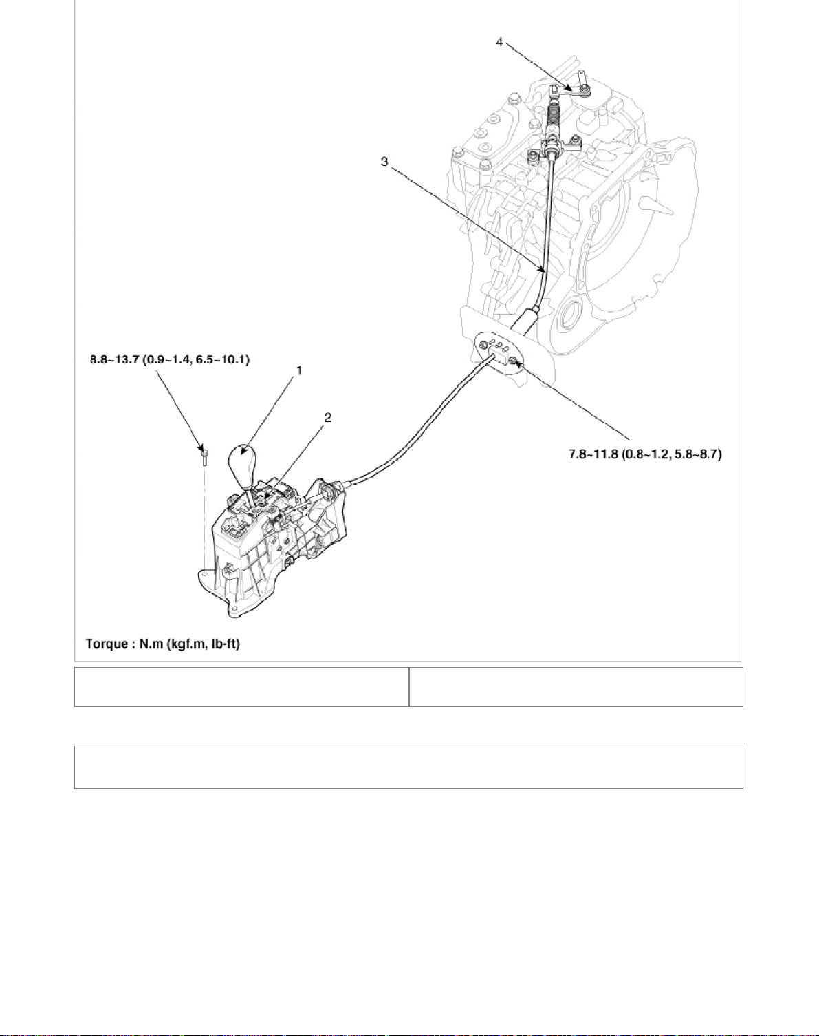
1. Shift lever knob
l
9
6
2. Shift lever assembly
3. Control cable assembly
4. Shift lever assembly(AT side)
Automatic Transaxle System > Automatic Transaxle Control System > Shift Lever > Repair
procedures
Remova
1. Pull the gear knob (A) in the directionof the "F" and remove it, and then remove the console upper cover (B). (Refer to
"Interior" in BD group)
Page 32
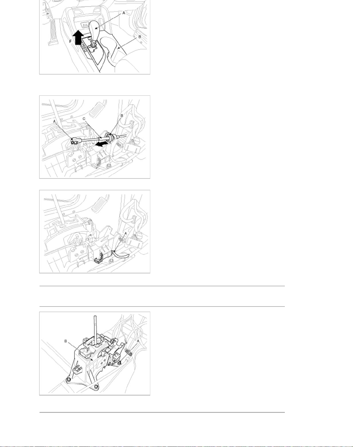
2. Remove the center console assembly. (Refer to "Interior" in BD group.)
T
b
T
6
3. Take off the clip (A) and the clamp (B) and then remove the shift cable (C).
4. Disconnect sports mode connector (A).
5. Remove the shift lever assembly (B) by removing the bolts (A-4ea).
ightening torque:
8.8 ~ 13.7 N.m (0.9 ~ 1.4 kgf.m, 6.5 ~ 10.1 l
6. Remove the shift cable assembly in the vehicle after removing the nuts (B) and the retainer (A).
ightening torque:
-ft)
Page 33
b
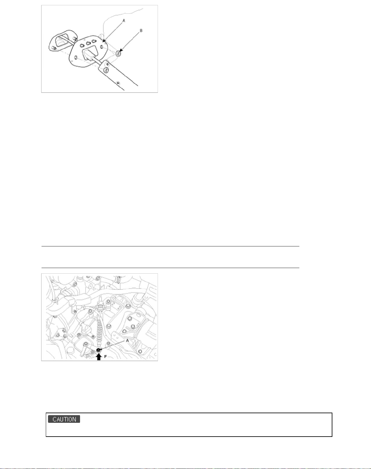
7. Remove the cable from the bracket at transaxle assembly side (Refer to "Automatic Transaxle" in this group).
n
T
b
n
6
8. Remove the shift cable at cabin room.
Inspectio
1. Check the damage and operation of the control cable.
2. Check the damage of the boot.
3. Check the damage and corrosion of the bushing.
4. Check the damage or weakening of the spring.
Adjustment
Adjusting method for T/M control cable
1. Set room side lever and T/M side lever to "N" position.
2. Connect room side lever and shift cable.
3. Push cable to "F" direction shown to eliminate FREE PLAY.
4. Tighten adjusting nut (A).
ightening torque:
7.8 ~ 11.8 N.m (0.8 ~ 1.2 kgf.m, 5.8 ~ 8.7 l
-ft)
5. After adjusting according Check to be sure that this part operates surely at each range of T/M side corresponding to
each position of room lever.
Installatio
1. Installation is the reverse of removal.
Set room side lever and T/M side lever to "N" position.
Page 34
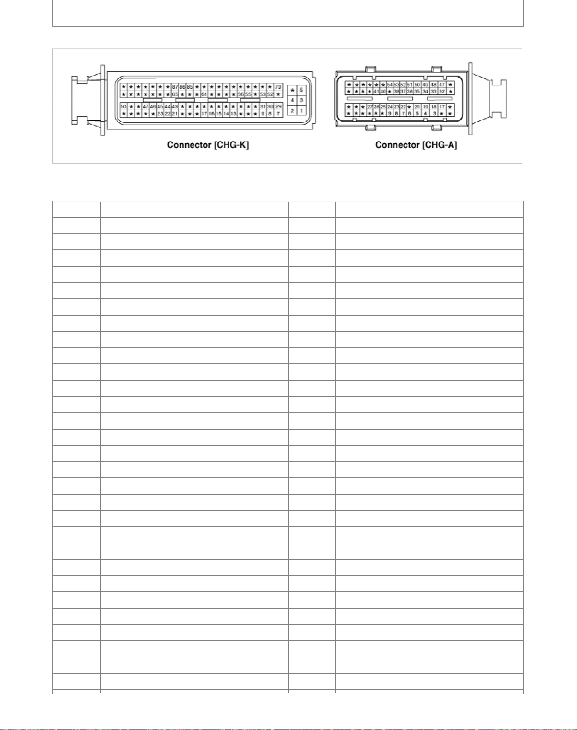
Automatic Transaxle System > Automatic Transaxle Control System > Transaxle Control
n
n
2
6
Module (TCM) > Schematic Diagrams
1. TCM connector and terminal functio
2. TCM terminal functio
Connector [CHG-A]
Pin Description Pin Description
1-31-
2 - 32 Shift solenoid F(SS-B)
3 Pressure control solenoid A(VFS-LINE) 33 Shift solenoid E(SS-A)
4 Torque Converter Clutch solenoid (VFS-T/Con) 34 Ground (Power 1)
5 Shift solenoid C(35R_VFS) 35 Ground (Power 2)
6 Input speed sensor power 36 Sports mode down switch
7 Output speed sensor power 37 Sports mode up switch
8 Input speed sensor signal 38 Sports mode Select switch
9 Output speed sensor signal 39 -
10 - 40 Inhibitor switch signal (S1)
11 - 41 -
12 - 42 -
13 - 43 -
14 - 44 -
15 - 45 -
16 - 46 -
17 Shift solenoid A(VFS-UD) 47 Solenoid supply power 1
18 Shift solenoid B(VFS-26) 48 Solenoid supply power 2
19 Shift lock solenoid 49 TCM Input power 1 (For solenoid)
20 Shift solenoid D(VFS-OD) 50 TCM Input power 2 (For solenoid)
21 - 51 Reserved
22 Rear lamp relay 52 Reserved
23 - 53 Oil temperature sensor (-)
24 Start relay 54 Oil temperature sensor (+)
25 Inhibitor switch signal (S2) 55 -
26 Inhibitor switch signal (S3) 56 -
27 Inhibitor switch signal (S4) 57 -
28 - 58 -
29 - 59 -
Page 35
Connector [CHG-K]
l
3
6
Pin Description Pin Description
1 Power ground 31 Power ground
2 Battery power (B+) 32 Battery power (B+)
3 Power ground 33 CAN High
4 Battery power (B+) 34 CAN Low
3. TCM Terminal input/ output signa
Connector [CHG-A]
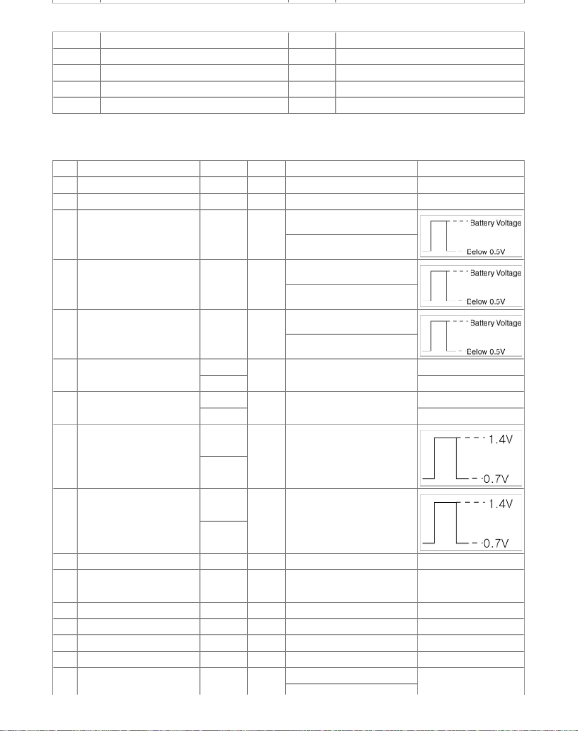
Pin Description Condition Type Level Test result
1-
2-
Pressure control solenoid A
3
4
5 Shift solenoid C(35R_VFS) Output
6 Input speed sensor power
7 Output speed sensor power
8 Input speed sensor signal
(VFS-LINE)
Torque Converter Clutch
solenoid (VFS-T/Con)
ON
OFF 0.3 V
ON
OFF 0.3 V
High
Low
Output
Output
Power 0V/7.5V
Power 0V/7.5V
Input 0.7V/1.4V
0V/Battery voltage level
9V < Battery voltage level < 16V
0V/Battery voltage level
9V < Battery voltage level < 16V
0V/Battery voltage level
9V < Battery voltage level < 16V
7.5V
7.5V
High
9 Output speed sensor signal
Low
10 -
11 -
12 -
13 -
14 -
15 -
16 -
Input 0.7V/1.4V
0V/Battery voltage level
Page 36
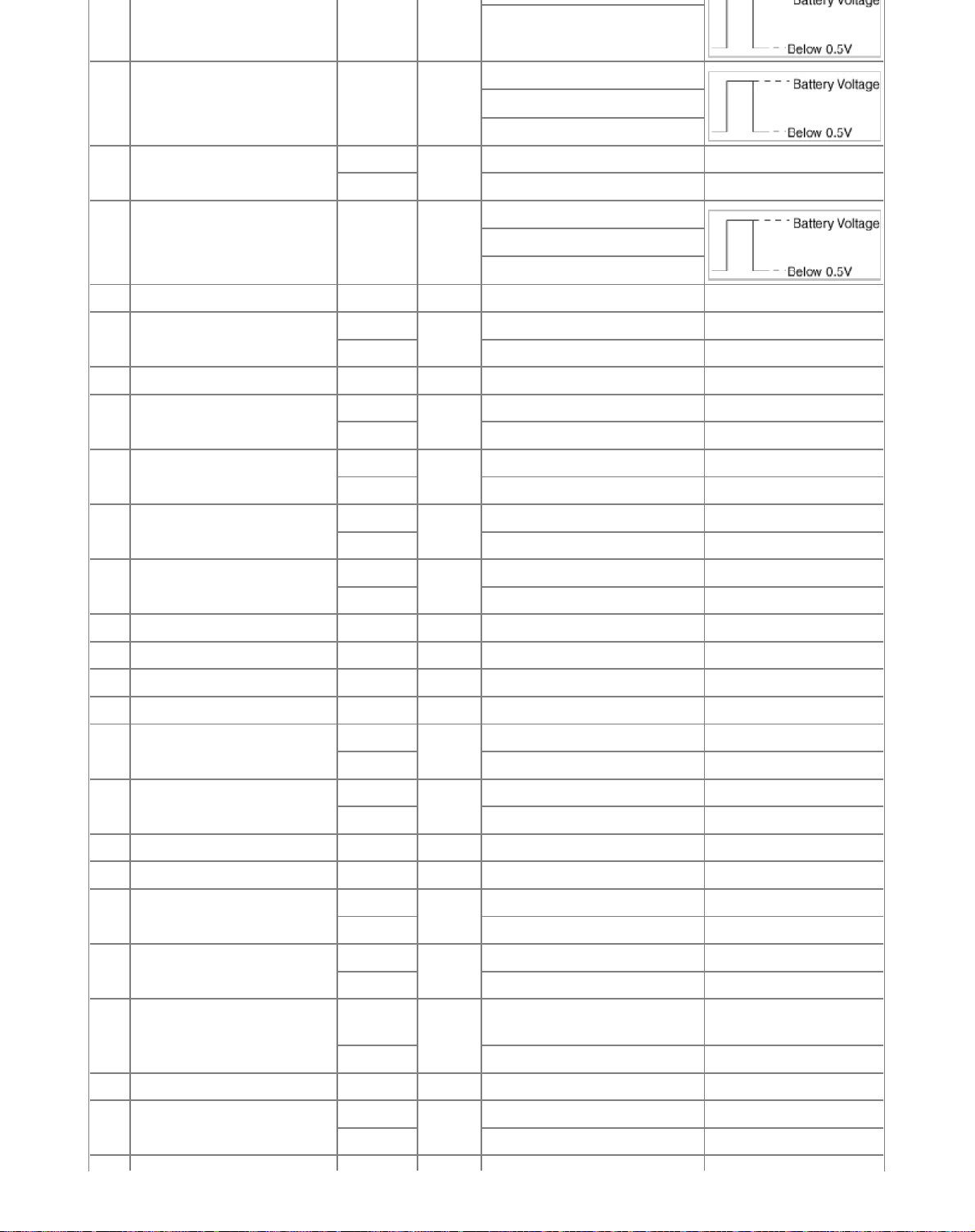
17 Shift solenoid A(VFS-UD) Output
4
6
Power supply : V_SOL2
0V/Battery voltage level
18 Shift solenoid B(VFS-26) Output
19 Shift lock solenoid
20 Shift solenoid D(VFS-OD) Output
21 -
22 Rear lamp relay
23 -
24 Start relay
25 Inhibitor switch signal (S2)
26 Inhibitor switch signal (S3)
27 Inhibitor switch signal (S4)
28 -
29 -
30 -
31 -
32 Shift solenoid F(SS-B)
33 Shift solenoid E(SS-A)
34 Ground (Power 1) Ground 0V 0V
35 Ground (Power 2) Ground 0V 0V
36 Sports mode down switch
37 Sports mode up switch
38 Sports mode select switch
39 -
40 Inhibitor switch signal (S1)
High
Low 9V < Battery voltage level < 16V 0.3 V
R ON
Other 9V < Battery voltage level < 16V Battery voltage level
High
Low 9V < Battery voltage level < 16V 0.3 V
High
Low 9V < Battery voltage level < 16V 0.3 V
High
Low 9V < Battery voltage level < 16V 0.3 V
High
Low 9V < Battery voltage level < 16V 0.3 V
High
Low 9V < Battery voltage level < 16V 0.3 V
High
Low 9V < Battery voltage level < 16V 0.3 V
Down ON
Other 9V < Battery voltage level < 16V Battery voltage level
Up ON
Other 9V < Battery voltage level < 16V Battery voltage level
Sport
mode
Other 9V < Battery voltage level < 16V Battery voltage level
High
Low 9V < Battery voltage level < 16V 0.3 V
Output
Output
Output
Input
Input
Input
Output
Output
Input
Input
Input
Input
9V < Battery voltage level < 16V
Power supply : V_SOL2
0V/Battery voltage level Battery voltage level
0V/Battery voltage level
9V < Battery voltage level < 16V
Power supply : V_SOL1
0V/Battery voltage level 0.3V
0V/Battery voltage level Battery voltage level
0V/Battery voltage level Battery voltage level
0V/Battery voltage level Battery voltage level
0V/Battery voltage level Battery voltage level
0V/Battery voltage level Battery voltage level
0V/Battery voltage level Battery voltage level
0V/Battery voltage level 0.3V
0V/Battery voltage level 0.3V
0V/Battery voltage level 0.3V
0V/Battery voltage level Battery voltage level
Page 37

42 -
5
6
43 -
44 -
45 -
46 -
47 Solenoid supply power 1
48 Solenoid supply power 2
49
50
51 -
52 -
53 Oil temperature sensor (-) Ground 0V 0V
54 Oil temperature sensor (+)
54 -
55 -
56 -
57 -
58 -
59 -
60 -
TCM Input power 1
(For solenoid)
TCM Input power 2
(For solenoid)
ON
Power
OFF 9V < Battery voltage level < 16V 0.3 V
ON
Power
OFF 9V < Battery voltage level < 16V 0.3 V
Power
Power
ON
Input 0V/3.3V
OFF 0.3V
0V/Battery voltage level Battery voltage level
0V/Battery voltage level Battery voltage level
Battery voltage level
Battery voltage level
9V < Battery voltage level < 16V
Battery voltage level
Battery voltage level
9V < Battery voltage level < 16V
Sensor level
(0V~3.3V)
Connector [CHG-K]
Pin Description Condition Type Level Test result
1 Power ground Ground 0V 0V
2 Battery power (B+)
3 Power ground Ground 0V 0V
4 Battery power (B+)
5 Power ground Ground 0V 0V
6 Battery power (B+) Power
ON
Power
OFF 9V < Battery voltage level < 16V 0.3 V
ON
Power
OFF 9V < Battery voltage level < 16V 0.3 V
0V/Battery voltage level Battery voltage level
0V/Battery voltage level Battery voltage level
Battery voltage level
Battery voltage level
9V < Battery voltage level < 16V
Automatic Transaxle System > Automatic Transaxle Control System > Transaxle Control
Module (TCM) > Repair procedures
Replacement
Page 38
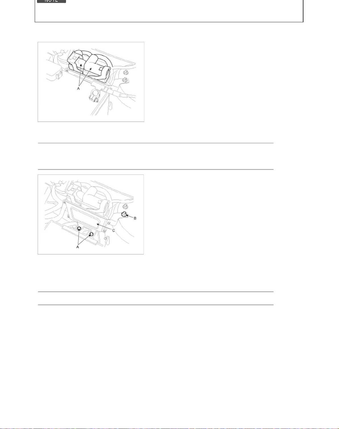
In the case of the vehicle equipped with immobilizer or button engine start system, perform "Key Teaching" procedure
T
b
b
6
6
together (Refer to "Immobilizer" or "Button Engine Start System in BE group).
1. Turn ignition switch OFF and disconnect the negative (-) battery cable.
2. Disconnect the TCM Connector (A).
3. Remove the battery (Refer to "Chargin System" in EE group).
4. Remove the mounting bolts (A) and nut (B), and then remove the TCM (C).
ightening torque:
(A) 21.6 ~ 32.4 N.m (2.2 ~ 3.3 kgf.m, 15.9 ~ 23.9 l
(B) 9.8 ~ 14.7 N.m (1.0 ~ 1.5 kgf.m, 7.2 ~ 10.9 l
-ft)
-ft)
TCM Problem Inspection Procedure
1. TEST TCM GROUND CIRCUIT: Measure resistance between TCM and chassis ground using the backside of TCM
harness connector as TCM side check point. If the problem is found, repair it.
Specification: Below 1Ω
2. TEST TCM CONNECTOR: Disconnect the TCM connector and visually check the ground terminals on TCM side and
harness side for bent pins or poor contact pressure. If the problem is found, repair it.
3. If problem is not found in Step 1 and 2, the TCM could be faulty. If so, make sure there were no DTC's before swapping
the TCM with a new one, and then check the vehicle again. If DTC's were found, examine this first before swapping
TCM.
4. RE-TEST THE ORIGINAL TCM: Install the original TCM (may be broken) into a known-good vehicle and check the
vehicle. If the problem occurs again, replace the original TCM with a new one. If problem does not occur, this is
intermittent problem (Refer to “Intermittent Problem Inspection Procedure” in Basic Inspection Procedure).
Adjustment
TCM Learning
When shift shock is occurred or parts related with the transaxle are replaced, TCM learning should be performed.
Page 39
• Transaxle assembly replacement
n
n
l
7
6
• TCM replacement
• TCM upgrading
1. TCM learning condition
- ATF temperature: 60~115°C (140~239°F)
2. TCM learning procedure
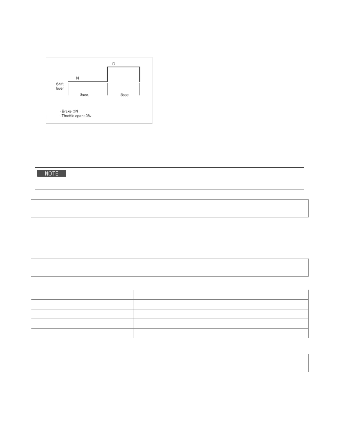
A. Stop learning
Repeat the below shift pattern four times or more with stepping on the brake.
B. Driving learning
1. Drive the vehicle through all gears at D range. Drive from stop to 1st to 2nd to 3rd to 4th to 5th to 6th with keeping
fixed throttle open.
2. Down shift from 6th to 5th, 5th to 4th, 4th to 3rd, 3rd to 2nd, 2nd to 1st.
3. Repeat the above driving pattern four times or more.
Up-shift throttle open : 15~30%
Automatic Transaxle System > Automatic Transaxle Control System > Input Speed Sensor
> Description and Operation
Descriptio
- Integrated one unit for input & output speed sensor
- Differential current type (low: 7mA, high: 14mA)
- Failsafe: 4th gear hold (D), 2nd ~ 4th manual shift (S)
Automatic Transaxle System > Automatic Transaxle Control System > Input Speed Sensor
> Specifications
Specificatio
Item Specification
Type Hall Effect Sensor, 2pins (Power: 9V, Signal)
Operation condition -40 ~150°C [-40 ~ 302°F]
Sensor length 52.7~52.9mm (2.0748~2.0827in.)
Air gap 0.95~1.65mm (0.0374~0.0650in.)
Automatic Transaxle System > Automatic Transaxle Control System > Input Speed Sensor
> Repair procedures
Remova
1. Remove the battery and the battery tray. (Refer to "Charging system" in EE group.)
2. Remove the under cover (A).
Page 40
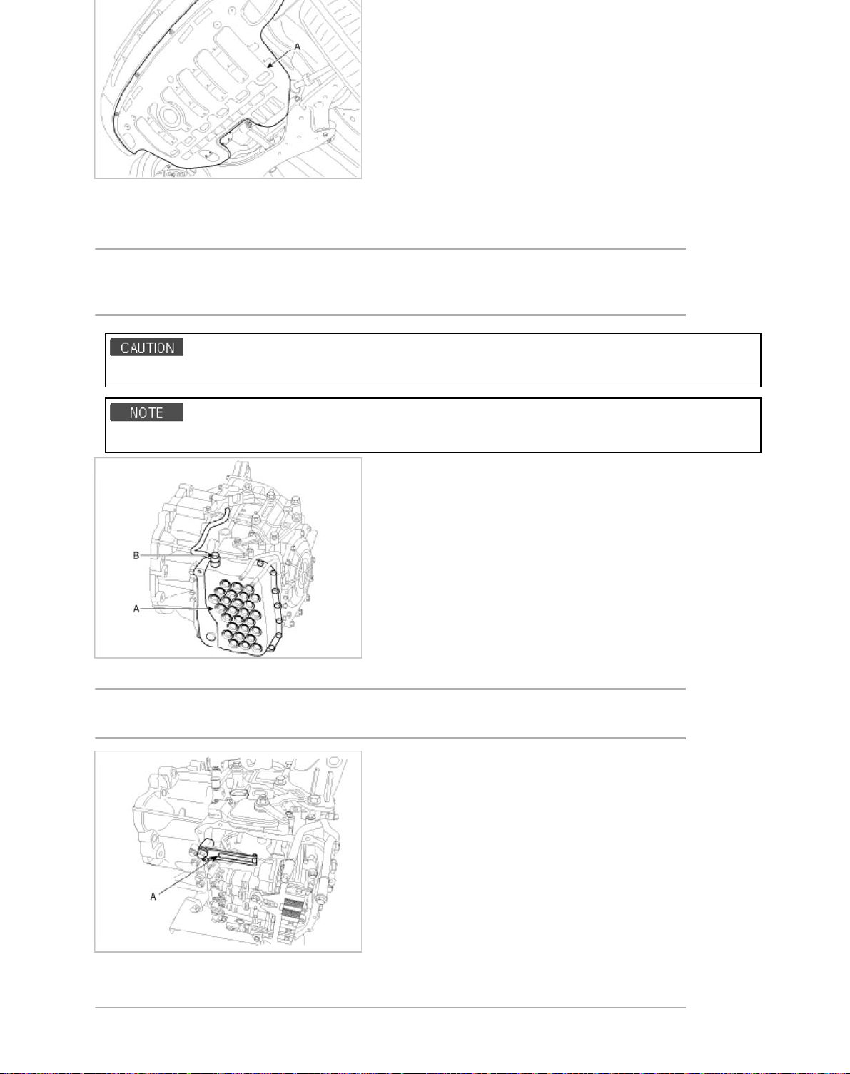
3. Replace new gasket and the plug after drining the automatic transaxle fluid by removing the drain plug.
T
b
b
T
2
6
(Refer to "Automatic transaxle system" in this group.)
4. Remove the valve body cover (A) and eyebolt (B).
ightening torque:
(A) 9.8 ~ 11.8 N.m (1.0 ~ 1.2 kgf.m, 7.2 ~ 8.7 l
(B) 34.3 ~ 44.1 N.m (3.5 ~ 4.5 kgf.m, 25.3 ~ 32.6 l
The gasket of the eyebolt use new one.
Remove installation bolts in the engin room first and then remove others under the vehicle.
-ft)
-ft)
5. Remove the plate and the detend spring (A) after removing the bolt.
ightening torque:
4.5 ~ 35.3 N.m (2.5 ~ 3.6 kgf.m, 18.1 ~ 26.0 lb-ft)
6. Remove the bolt (3ea) after disconnecting the solenoid valve connector (A) and the oil temperature sensor connector
(B).
Page 41
T
9.8 ~ 11.8 N.m (1.0 ~ 1.2 kgf.m, 7.2 ~ 8.7 l
b
T
b
T
b
9
6
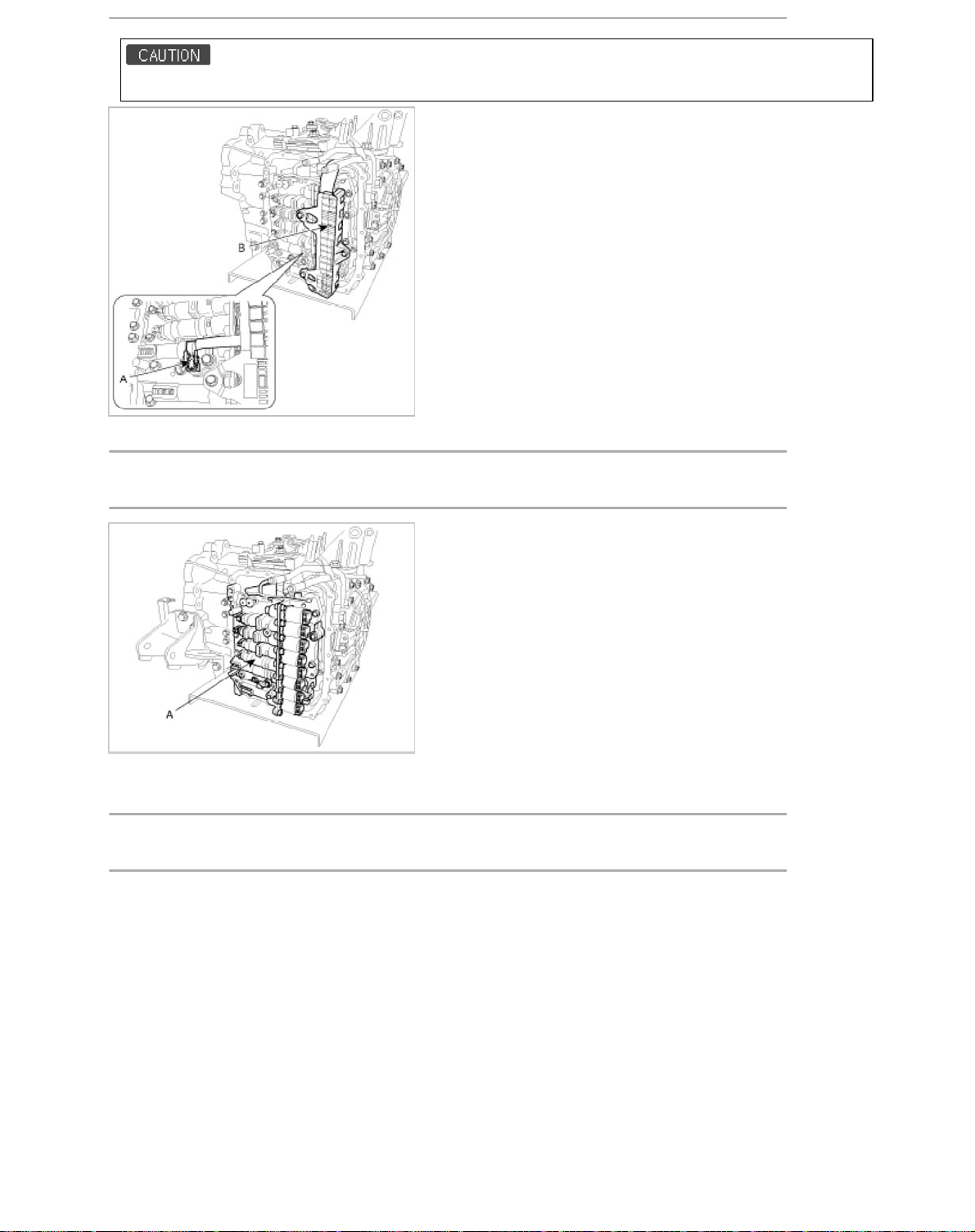
Be careful not to damage the harness lock connector.
7. Remove the valve body assembly (A).
ightening torque:
9.8 ~ 11.8 N.m (1.0 ~ 1.2 kgf.m, 7.2 ~ 8.7 l
-ft)
-ft)
8. Disconnect the input & output speed sensor connector(A).
9. Remove the input & output speed sensor (B) after removing the bolts(2ea).
ightening torque:
9.8 ~ 11.8 N.m (1.0 ~ 1.2 kgf.m, 7.2 ~ 8.7 l
-ft)
Page 42
Installatio
n
n
n
l
6
1. Installation is the reverse of removal.
After replacement or reinstallation procedure of the valve body assembly, must perform procedures below.
• Continue to apply liquid gasket at application points at the valve body cover with Ø2.5mm (0.0984in.) thickness.
Liquid gasket Part name :
Threebond 1281B or LOCTITE FMD-546
• Adding automaticmatic transaxle fluid. (Refer to "automaticmatic transaxle system" in this group.)
Automatic Transaxle System > Automatic Transaxle Control System > Output Speed
Sensor > Description and Operation
Descriptio
- Integrated one unit for input & output speed sensor
- Differential current type (low: 7mA, high: 14mA)
- Failsafe: 4th gear hold (D), 2nd ~ 4th manual shift (S)
Automatic Transaxle System > Automatic Transaxle Control System > Output Speed
Sensor > Specifications
Specificatio
Item Specification
Type
Operation condition -40 ~150°C [-40 ~ 302°F]
Sensor length 33.6~33.8mm (1.3228~1.3307in.)
Air gap 0.25~1.9mm (0.0098~0.0748in.)
Hall Effect Sensor, 2pins
(Power: 9V, Signal)
Automatic Transaxle System > Automatic Transaxle Control System > Output Speed
Sensor > Repair procedures
Remova
Page 43
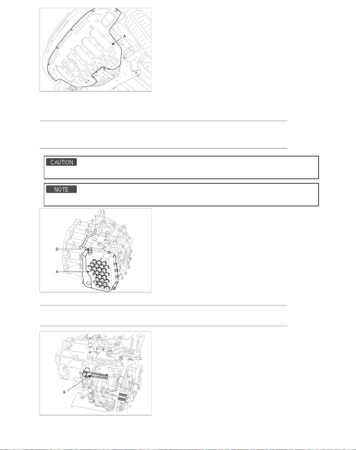
2. Remove the under cover (A).
T
b
b
T
2
6
3. Replace new gasket and the plug after drining the automatic transaxle fluid by removing the drain plug.
(Refer to "Automatic transaxle system" in this group.)
4. Remove the valve body cover (A) and eyebolt (B).
ightening torque:
(A) 9.8 ~ 11.8 N.m (1.0 ~ 1.2 kgf.m, 7.2 ~ 8.7 l
(B) 34.3 ~ 44.1 N.m (3.5 ~ 4.5 kgf.m, 25.3 ~ 32.6 l
The gasket of the eyebolt use new one.
-ft)
-ft)
Remove installation bolts in the engin room first and then remove others under the vehicle.
5. Remove the plate and the detend spring (A) after removing the bolt.
ightening torque:
4.5 ~ 35.3 N.m (2.5 ~ 3.6 kgf.m, 18.1 ~ 26.0 lb-ft)
6. Remove the bolt (3ea) after disconnecting the solenoid valve connector (A) and the oil temperature sensor connector
Page 44
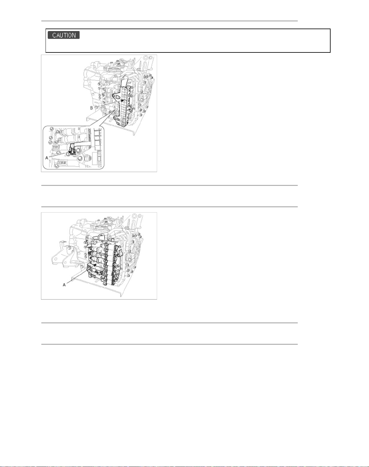
T
ightening torque:
b
T
b
T
b
2
6
9.8 ~ 11.8 N.m (1.0 ~ 1.2 kgf.m, 7.2 ~ 8.7 l
Be careful not to damage the harness lock connector.
7. Remove the valve body assembly (A).
-ft)
ightening torque:
9.8 ~ 11.8 N.m (1.0 ~ 1.2 kgf.m, 7.2 ~ 8.7 l
8. Disconnect the input & output speed sensor connector (A).
9. Remove the input & output speed sensor (B) after removing the bolts(2ea).
ightening torque:
9.8 ~ 11.8 N.m (1.0 ~ 1.2 kgf.m, 7.2 ~ 8.7 l
-ft)
-ft)
Page 45
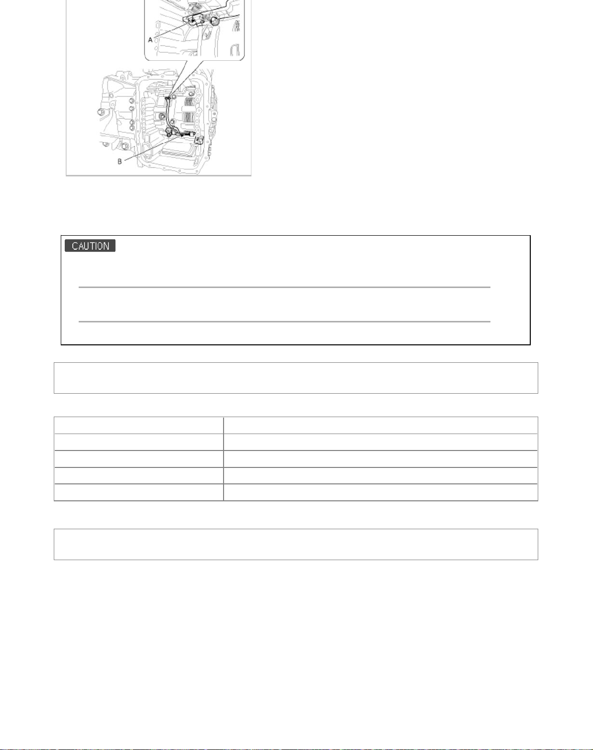
Installatio
n
n
l
3
6
1. Installation is the reverse of removal.
After replacement or reinstallation procedure of the valve body assembly, must perform procedures below.
• Continue to apply liquid gasket at application points at the valve body cover with Ø2.5mm (0.0984in.) thickness.
Liquid gasket Part name :
Threebond 1281B or LOCTITE FMD-546
• Adding automaticmatic transaxle fluid. (Refer to "automaticmatic transaxle system" in this group.)
Automatic Transaxle System > Automatic Transaxle Control System > Transaxle Oil
Temperature Sensor > Specifications
Specificatio
Item Specification
Type Negative Thermal Coefficient Type
Operation temperature -40~165°C [-40~329°F]
Resistance 4.81kΩ~39 Ω
Failsafe Oil temperature set to default value [80°C(176°F)]
Automatic Transaxle System > Automatic Transaxle Control System > Transaxle Oil
Temperature Sensor > Repair procedures
Remova
1. Remove the battery and the battery tray. (Refer to "Charging system" in EE group.)
2. Remove the under cover (A).
Page 46
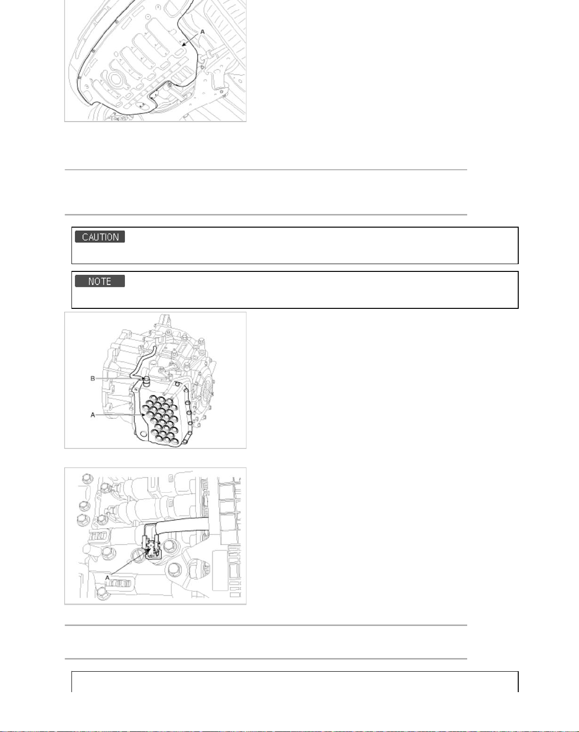
3. Replace new gasket and the plug after drining the automatic transaxle fluid by removing the drain plug.
T
b
b
T
b
4
6
(Refer to "Automatic transaxle system" in this group.)
4. Remove the valve body cover (A) and eyebolt (B).
ightening torque:
(A) 9.8 ~ 11.8 N.m (1.0 ~ 1.2 kgf.m, 7.2 ~ 8.7 l
(B) 34.3 ~ 44.1 N.m (3.5 ~ 4.5 kgf.m, 25.3 ~ 32.6 l
The gasket of the eyebolt use new one.
Remove installation bolts in the engin room first and then remove others under the vehicle.
-ft)
-ft)
5. Disconnect the oil temperature sensor connector (A).
6. Remove the oil temperature sensor (A) after removing a bolt.
ightening torque:
9.8 ~ 11.8 N.m (1.0 ~ 1.2 kgf.m, 7.2 ~ 8.7 l
-ft)
Page 47
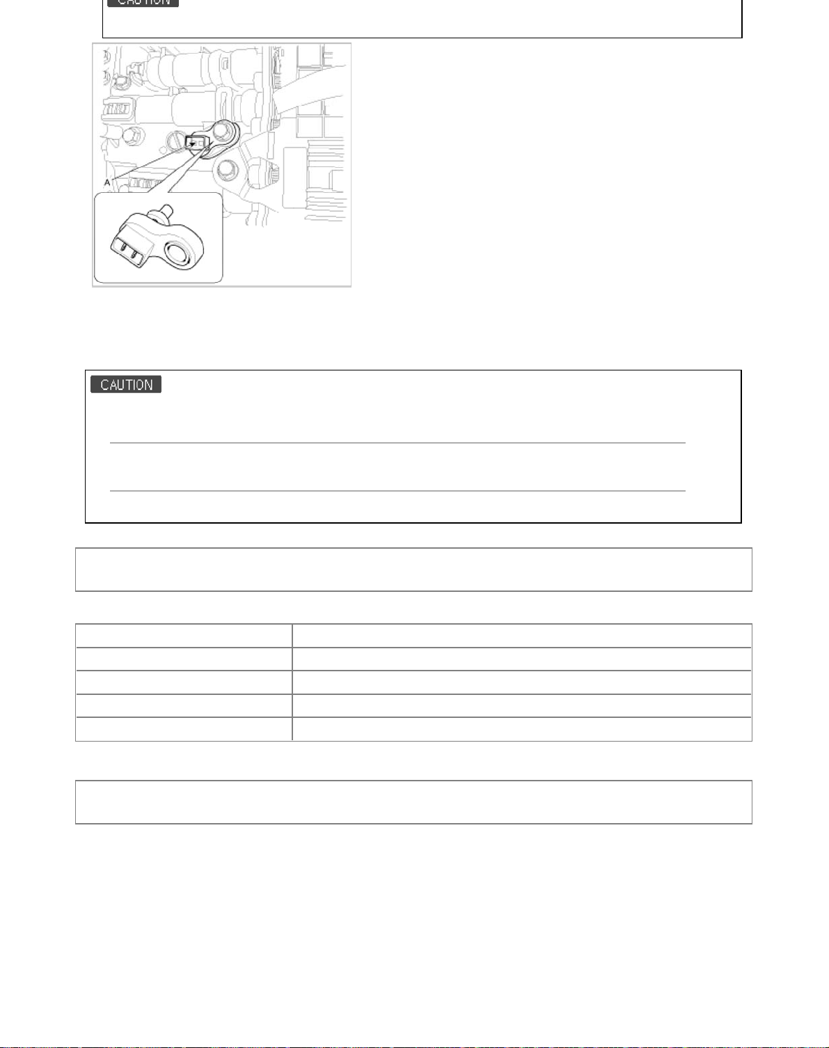
Be careful not to damage the harness lock connector.
n
n
l
5
6
Installatio
1. Installation is the reverse of removal.
After replacement or reinstallation procedure of the valve body assembly, must perform procedures below.
• Continue to apply liquid gasket at application points at the valve body cover with Ø2.5mm (0.0984in.) thickness.
Liquid gasket Part name :
Threebond 1281B or LOCTITE FMD-546
• Adding automaticmatic transaxle fluid. (Refer to "automaticmatic transaxle system" in this group.)
Automatic Transaxle System > Automatic Transaxle Control System > Inhibiter Switch >
Description and Operation
Descriptio
Item Specification
Type Combination of output signals from 4 terminals
Power supply 12V
Range detection 7-position (P, R, N, D, X, Y, Z)
Failsafe 1st, 2nd gear is prohibited.
Automatic Transaxle System > Automatic Transaxle Control System > Inhibiter Switch >
Repair procedures
Remova
1. Set room side lever and T/M side lever to "N" position.
2. Remove the battery and the battery tray. (Refer to "Charging system" in EE group.)
3. Remove the air cleaner assembly. (Refer to "Intake manifold" in EM group.)
4. Remove the shift cable mounting nut (B).
5. Disconnect the inhibitor switch connector (A).
Page 48
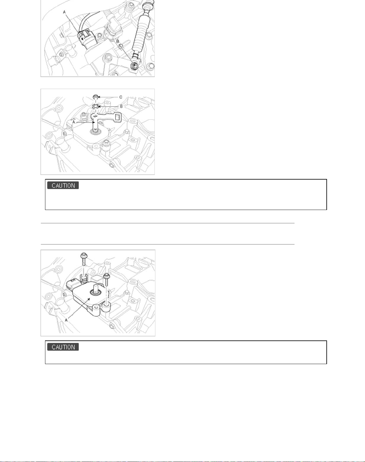
6. Remove the manual control lever (A) and the washer (B) after removing a nut (C).
T
b
n
6
6
When installing, fix the manual control lever and the inhibitor switch with Ø5mm (0.1969in.) fixing jig.
And then tighten the inhibitor assembly mounting bolts.
7. Remove the inhibitor assembly (A) after removing the bolts (2ea).
ightening torque:
9.8 ~ 11.8 N.m (1.0 ~ 1.2 kgf.m, 7.2 ~ 8.7 l
-ft)
When installing, tighten the inhibitor assembly mounting bolt lightly.
Installatio
1. Installation is the reverse of removal.
Page 49

Body (Interior and Exterior) > General Information > Specifications
s
Specification
Items Specification
Hood Type Rear hinged, front opening type
Front Door Construction Front hinged, full door construction
Regulator system Wire-drum type
Locking system Pin-fork system
Rear Door Construction Front hinged, full door construction
Regulator system Wire-drum type
Locking system Pin-fork system
Tail Gate Type Front hinged, gas lifter type
Seat Belts Front 3 point type with Emergency Locking Retractor (E.L.R)
Rear 3 point type with Emergency Locking Retractor (E.L.R)
2 point type
Tightening Torque
Items N.m Kgf.m lb-ft
Front andrear doors Door hinge to body 34.3 ~ 41.2 3.5 ~ 4.2 25.3 ~ 30.4
Door hinge to door 9.8 ~ 19.6 1.0 ~ 2.0 7.2 ~ 14.5
Door checker to door 3.9 ~ 5.9 0.4 ~ 0.6 2.9 ~ 4.3
Door checker to body 16.7 ~ 21.6 1.7 ~ 2.2 12.3 ~ 15.9
Door glass mounting bolt 6.9 ~ 10.8 0.7 ~ 1.1 5.1 ~ 8.0
Outside handle base mounting bolt 6.9 ~ 10.8 0.7 ~ 1.1 5.1 ~ 8.0
Door channel mounting nuts 6.9 ~ 10.8 0.7 ~ 1.1 5.1 ~ 8.0
Latch mounting bolts 6.9 ~ 10.8 0.7 ~ 1.1 5.1 ~ 8.0
Door module mounting bolts 6.9 ~ 10.8 0.7 ~ 1.1 5.1 ~ 8.0
Door striker mounting bolts 8.8 ~ 13.7 0.9 ~ 1.4 6.5 ~ 10.1
Tail gate Tail gate hinge to tail gate 21.6 ~ 26.5 2.2 ~ 2.7 15.9 ~ 19.5
Tail gate hinge to body 21.6 ~ 26.5 2.2 ~ 2.7 15.9 ~ 19.5
Tail gate latch mounting bolts 6.9 ~ 10.8 0.7 ~ 1.1 5.1 ~ 8.0
Tail gate striker mounting bolts 21.6 ~ 26.5 2.2 ~ 2.7 15.9 ~ 19.5
Hood Hood hinge to body 21.6 ~ 26.5 2.2 ~ 2.7 15.9 ~ 19.5
Hood hinge to hood 21.6 ~ 26.5 2.2 ~ 2.7 15.9 ~ 19.5
Hood latch to body 7.8 ~ 11.8 0.8 ~ 1.2 5.8 ~ 8.7
Seat Front seat mounting bolts 44.1 ~ 58.8 4.5 ~ 6.0 32.5 ~ 43.4
Front seat frame mounting bolts 44.1 ~ 58.8 4.5 ~ 6.0 32.5 ~ 43.4
Rear seat mounting bolts 44.1 ~ 58.8 4.5 ~ 6.0 32.5 ~ 43.4
Seat belt Height adjuster mounting bolts 39.2 ~ 53.9 4.0 ~ 5.5 28.9 ~ 39.8
Front seat belt upper anchor mounting bolt 39.2 ~ 53.9 4.0 ~ 5.5 28.9 ~ 39.8
Front seat belt lower anchor mounting bolt 39.2 ~ 53.9 4.0 ~ 5.5 28.9 ~ 39.8
Front seat belt retractor mounting bolt 39.2 ~ 53.9 4.0 ~ 5.5 28.9 ~ 39.8
Rear seat belt lower anchor mounting bolt 39.2 ~ 53.9 4.0 ~ 5.5 28.9 ~ 39.8
Page 50
Seat belt buckle mounting bolt 39.2 ~ 53.9 4.0 ~ 5.5 28.9 ~ 39.8
p
Quarter fixed glass Quarter fixed glass mounting nuts 3.9 ~ 4.4 0.4 ~ 0.45 2.9 ~ 3.3
Outside rearview mirror Outside rearview mirror mounting nuts 6.9 ~ 10.8 0.7 ~ 1.1 5.1 ~ 8.0
Panoramaroof Panoramaroof mounting nuts 19.6 ~ 29.4 2.0 ~ 3.0 14.5 ~ 21.7
Panoramaroof mounting bolts 19.6 ~ 29.4 2.0 ~ 3.0 14.5 ~ 21.7
Panoramaroof earthing mounting bolt 10.8 ~ 13.7 1.1 ~ 1.4 8.0 ~ 10.1
Body (Interior and Exterior) > General Information > Special Service Tools
S
ecial Tools
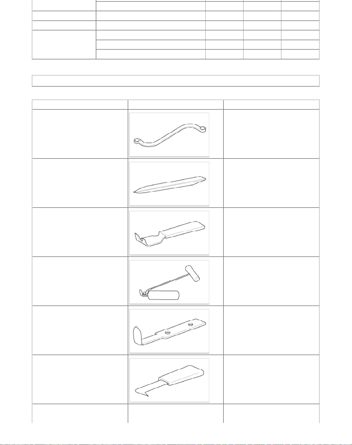
Tool (Number and name) Illustration Use
09793-21000
Door hinge adjusting wrench
Adjustment, removal and installationof
the door hinge
09800-21000
Ornament remover
09853-31000
Headliner clip remover
09861-31100
Sealant cut-out tool
09861-31200
Sealant cutting blade
Trim removal
Headliner clip removal
Cutting windshield sealant
(Use with 09861-31200)
Cutting windshield sealant
(Use with 09861-31100)
09861-31000
Windshield molding remover
09880-4F000
Hog ring clip installer
Windshield molding removal
Hog ring clip Installation
Page 51
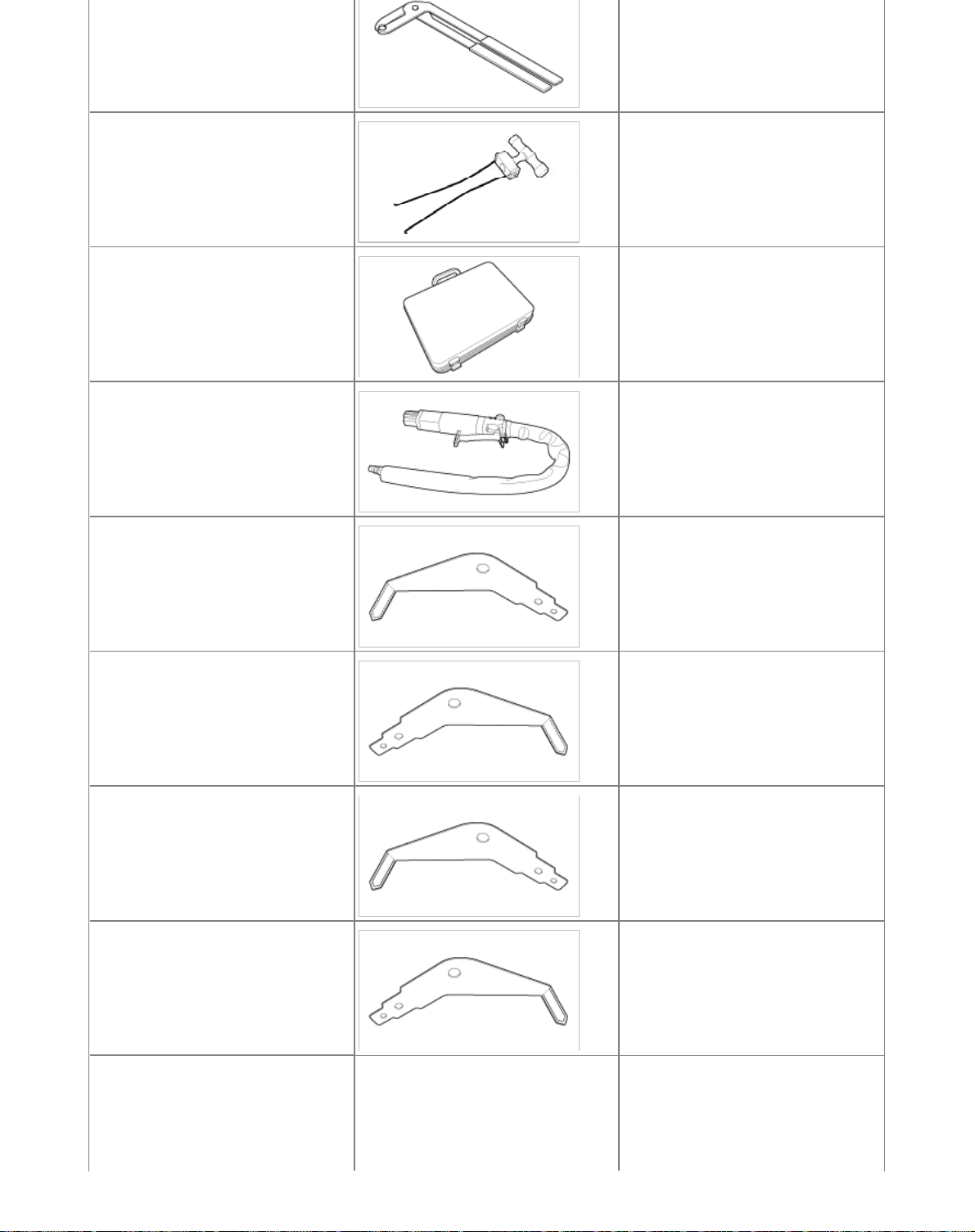
09840-1M100
Air vent remover
Air vent removal
09816-2P100
Power silent cutting tool
09816-2P110
Air power tool
09816-2P121
Cutter-1
09816-2P122
Cutter-2
Tool box for removing panorama sunroof
Air tool for installing blade
Blade for removing the front and side
area of panorama sunroof
(This blade has a inclination to push
upward.)
Blade for removing the front and side
area of panorama sunroof
(This blade has a inclination to push
upward.)
09816-2P123
Cutter-3
09816-2P124
Cutter-4
09816-2P130
Cutter-10
Blade for removing the front and side
area of panorama sunroof
(This blade has a inclination to push
downward.)
Blade for removing the front and side
area of panorama sunroof
(This blade has a inclination to push
downward.)
Blade for removing the edge area of
panorama sunroof
Page 52
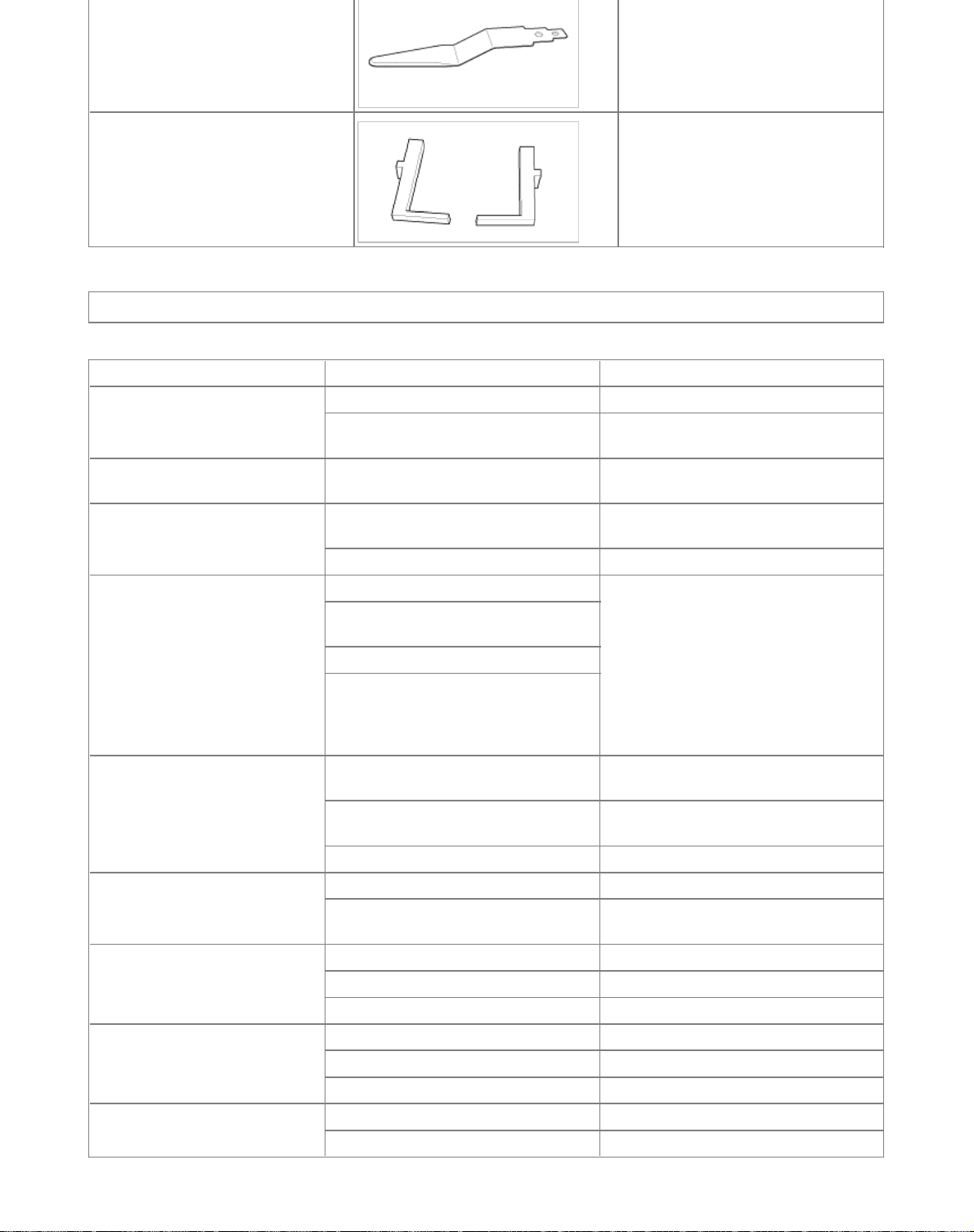
09816-2S100
g
Fixed glass fixture
Installation the fixed glass
Body (Interior and Exterior) > General Information > Troubleshooting
Troubleshootin
Symptom Suspect Area Remedy
Water leaks from panoramaroof Deteriorated roof lid weatherstrip Replace
Excessive roof lid-to-body clearance
andImproperly fitted weatherstrip
Wind noise around sunroof Loose or deformed deflector, gapsIn body
work
Noise heard when opening/ closing
panoramaroof
Motor runs but sunroof does not
move or moves only partially
Noise in motor (clutch slipping noise
from motor when sunroof is fully
opened or closed is not an unusual
noise
Door glass fails to operateUp and
Down
Door does not open or
closecompletely
Hood does not open or close
completely
Water leak through windshield and
rear window
Foreign particles lodged in guide rail Check drive cable and guide rails for
Loose guide rails and lid Retighten
Foreign particles lodged in guide rail Adjust or replace
Incorrect engagement of motor pinion with
drive cable
Decrease in motor`s clutch slipping force
Increased sunroof sliding resistance or
interference of sunroof with drive cables,
weatherstrip, etc. due to maladjustment of
sunroof
Incorrect engagement of motor pinion with
drive cable
Worn out or damaged motor pinion
bearing
Worn out or deformed drive cable Replace
Incorrect window glass installation Adjust position
Damaged or faulty regulator arm or
regulator
Incorrect door installation Adjust position
Defective door check assembly Correct or replace
Door hinge requires grease Apply grease
Striker and latch not properly aligned Adjust
Incorrectly installed hood Adjust
Incorrect hood bumper height Adjust
Defective seal Fill with sealant
Defective flange Correct
Adjust
Retighten adjust or replace
foreign particles
Check pinion installation and retighten
motor
Replace motor assembly
Correct or replace
Page 53
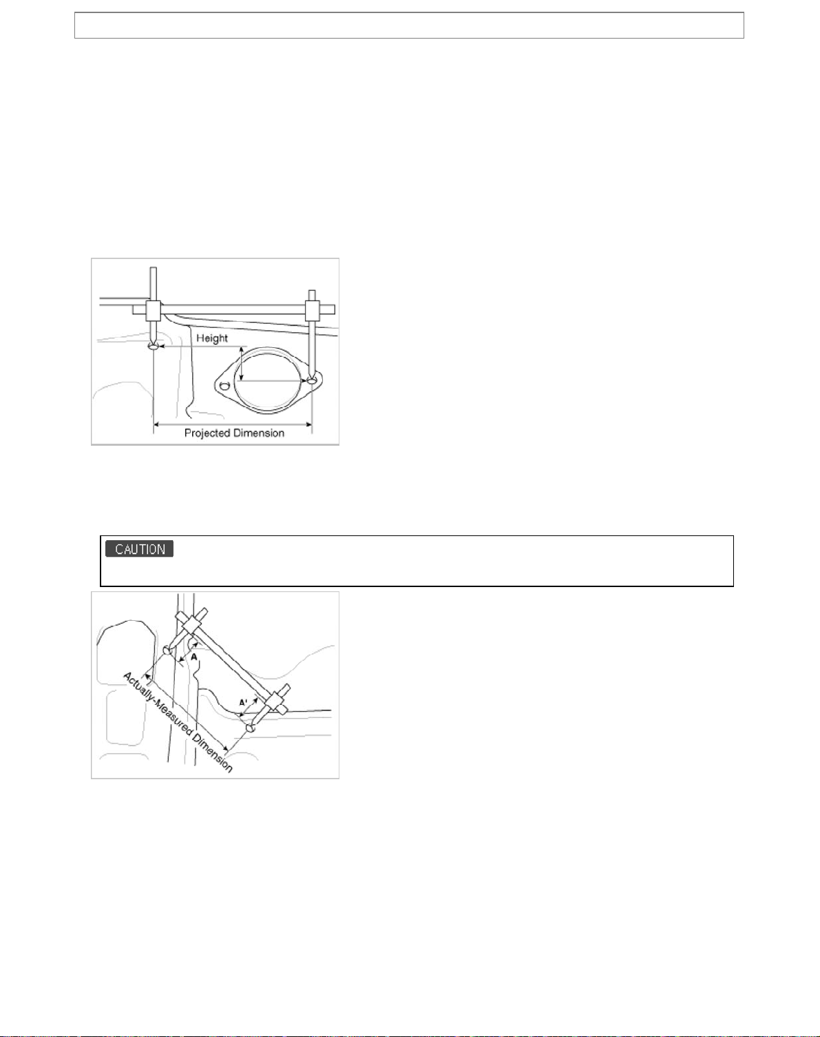
Body (Interior and Exterior) > Body Dimensions > General Information
l
d
Genera
1. Basically, all measurements in this manual are taken with a tracking gauge.
2. When a measuring tape is used, check to be sure there is no elongation, twisting or bending.
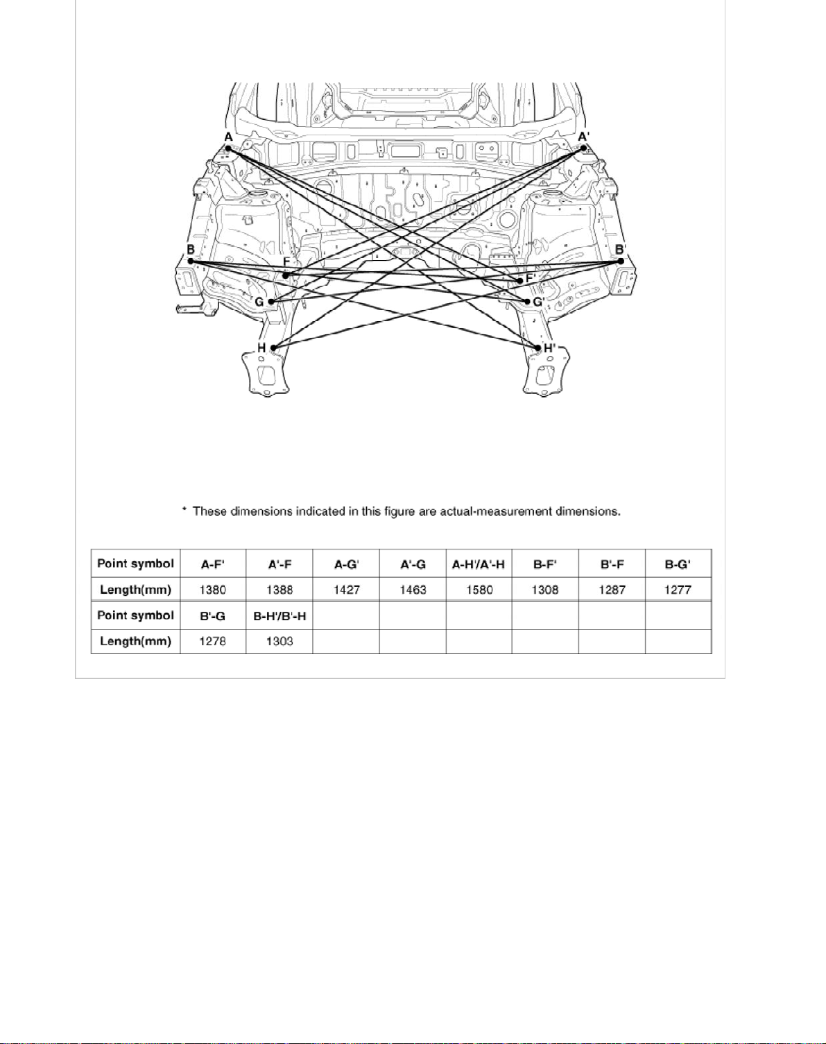
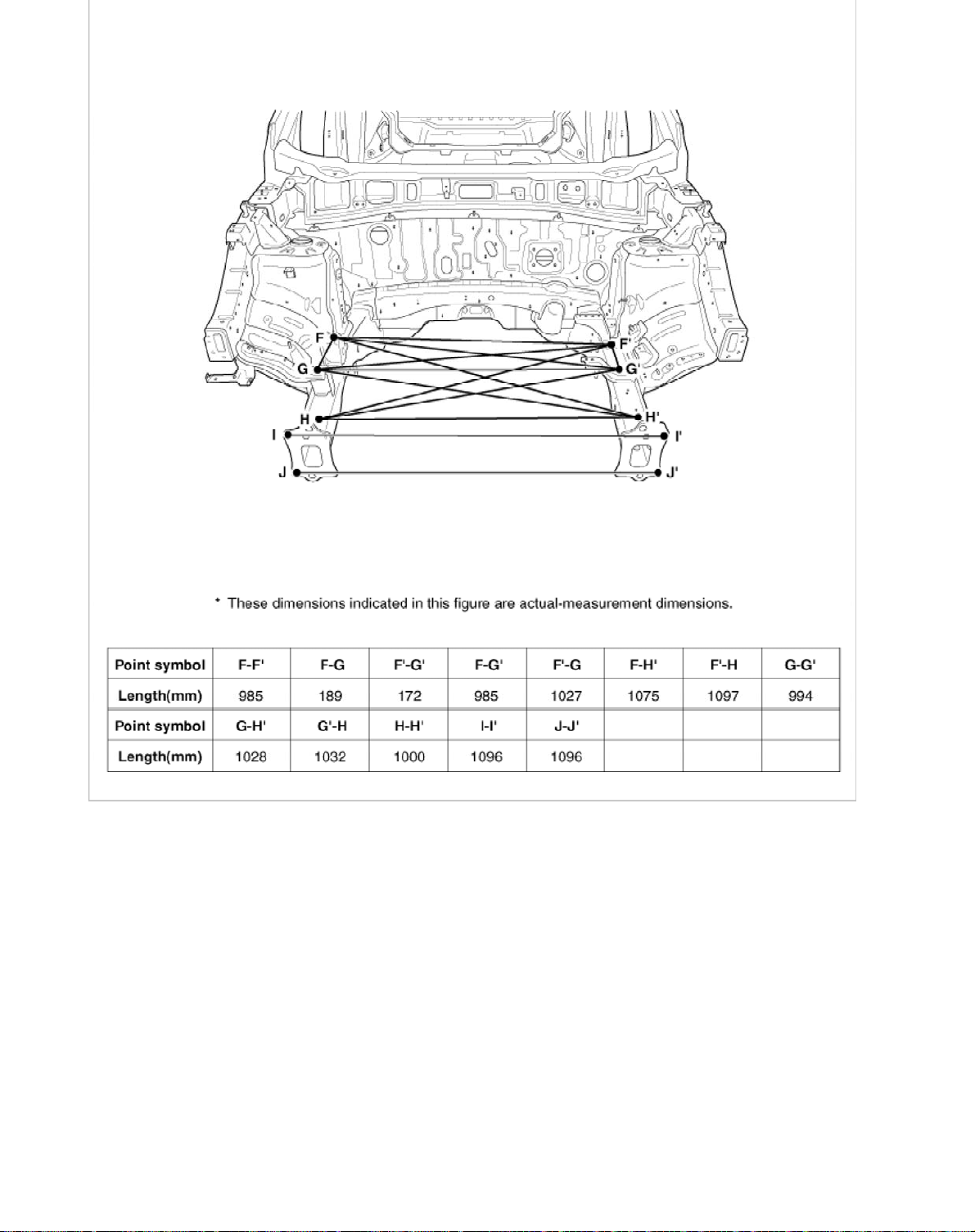
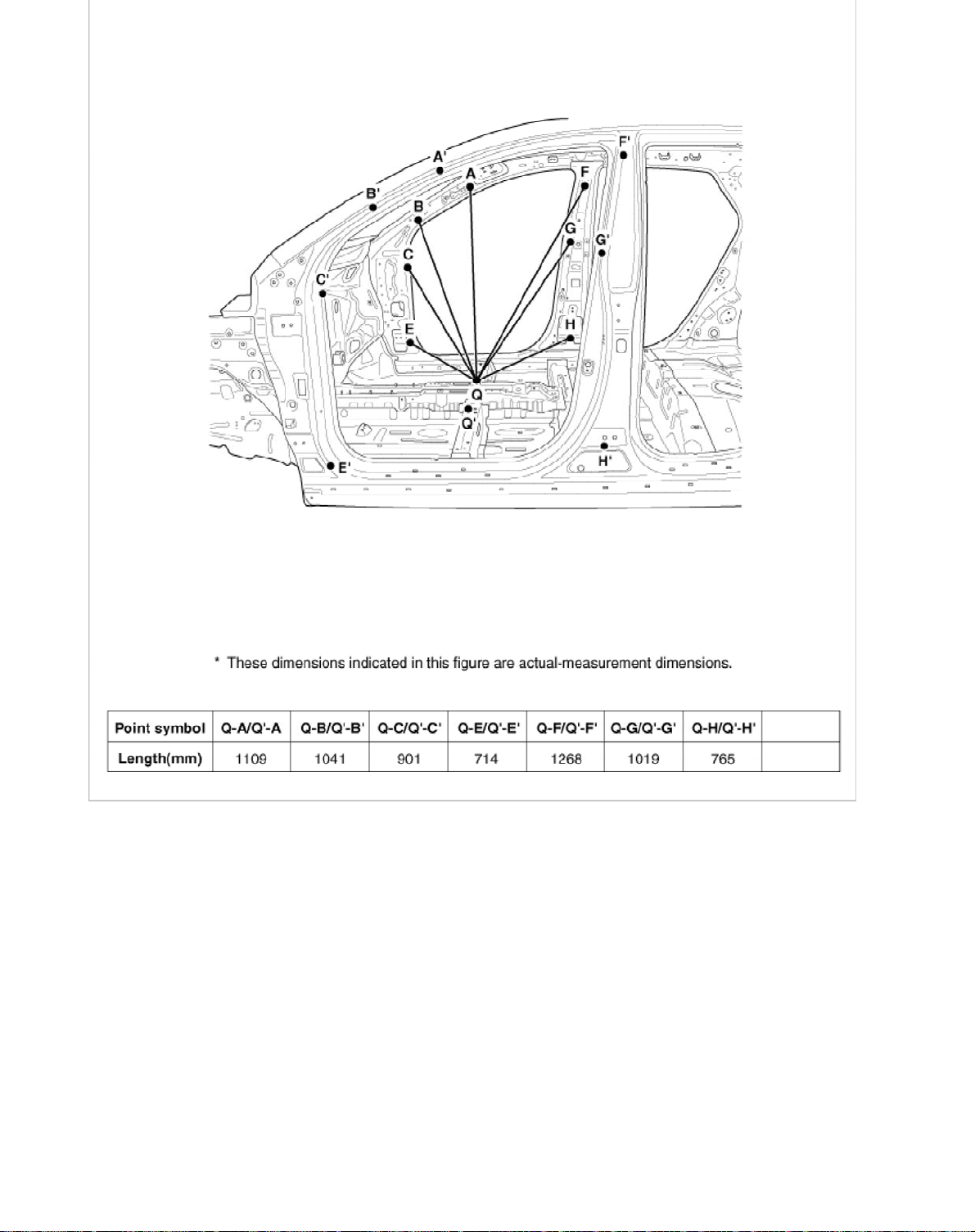
3. For measuring dimensions, both projected dimension and actual-measurement dimension are used in this manual.
Measurement Metho
Projected Dimensions
1. These are the dimensions measured when the measurement points are projected into the reference plane, and are the
reference dimensions used for body alterations.
2. If the length of the tracking gauge probes is adjustable, make the measurement by lengthening one probe by the amount
equivalent to the difference in height of the two surfaces.
Actual-Measurement Dimensions
1. These dimensions indicate the actual linear distance between measurement points, and are the reference dimensions for
use if a tracking gauge is used for measurement.
2. Measure by first adjusting both probes to the same length (A=A').
Check the probes and gauge itself to make sure there is no free play.
Measurement Point
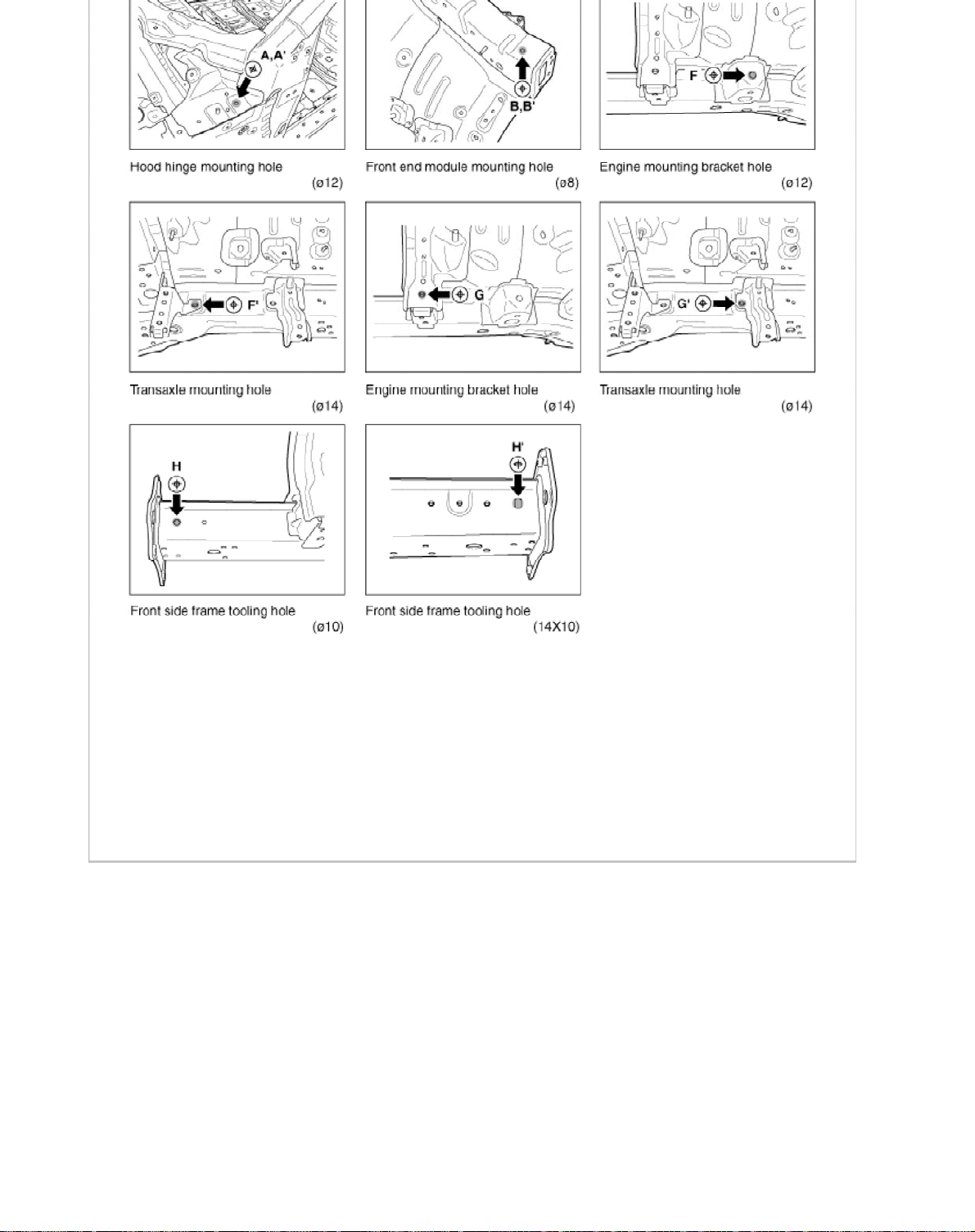
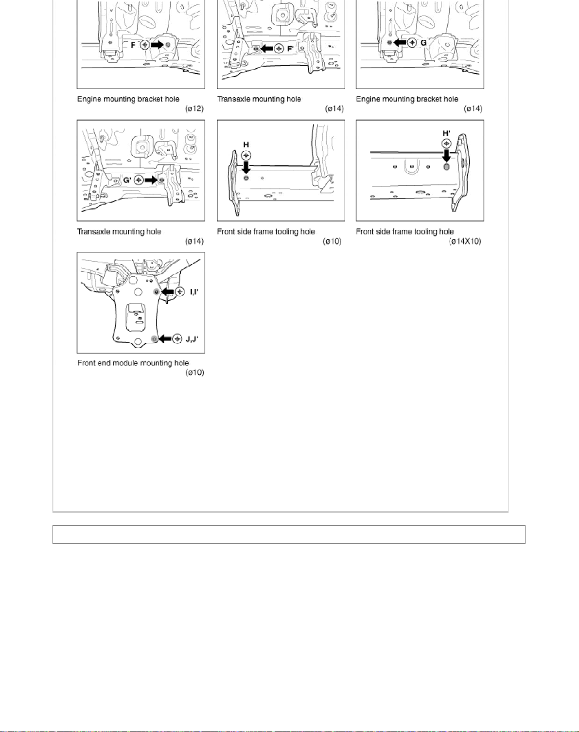
1. Measurements should be taken at the hole center.
Page 54
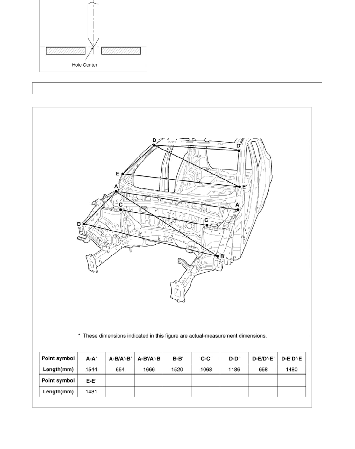
Body (Interior and Exterior) > Body Dimensions > Front Body > Body Repair
y A
Front bod
Page 55
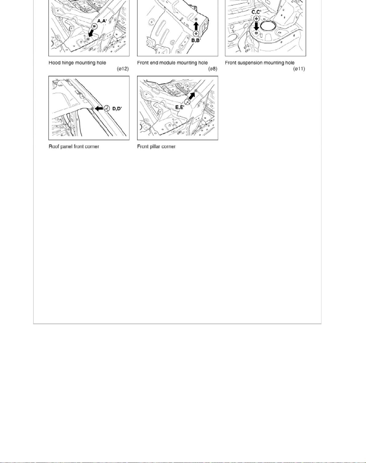
Front body B
Page 56
Page 57
Front body C
Page 58
Page 59
Body (Interior and Exterior) > Body Dimensions > Side Body > Body Repair
y A
Side bod
Page 60
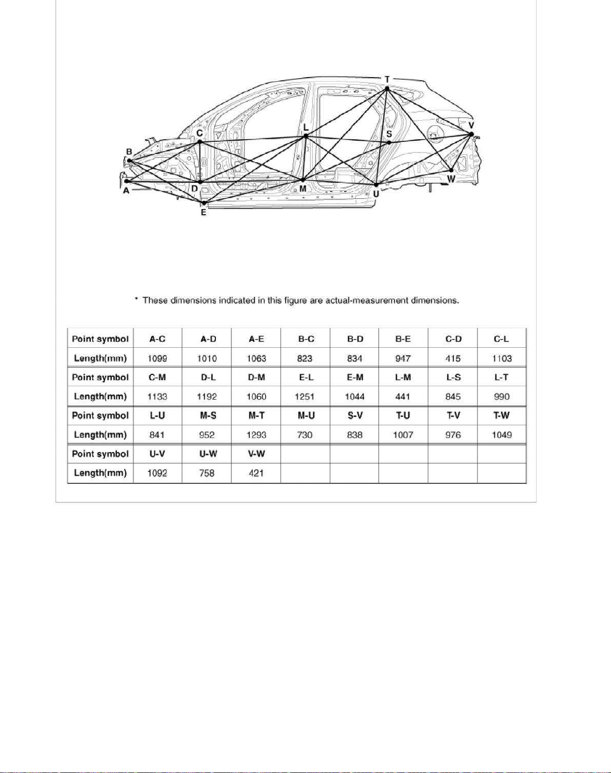
2
Page 61
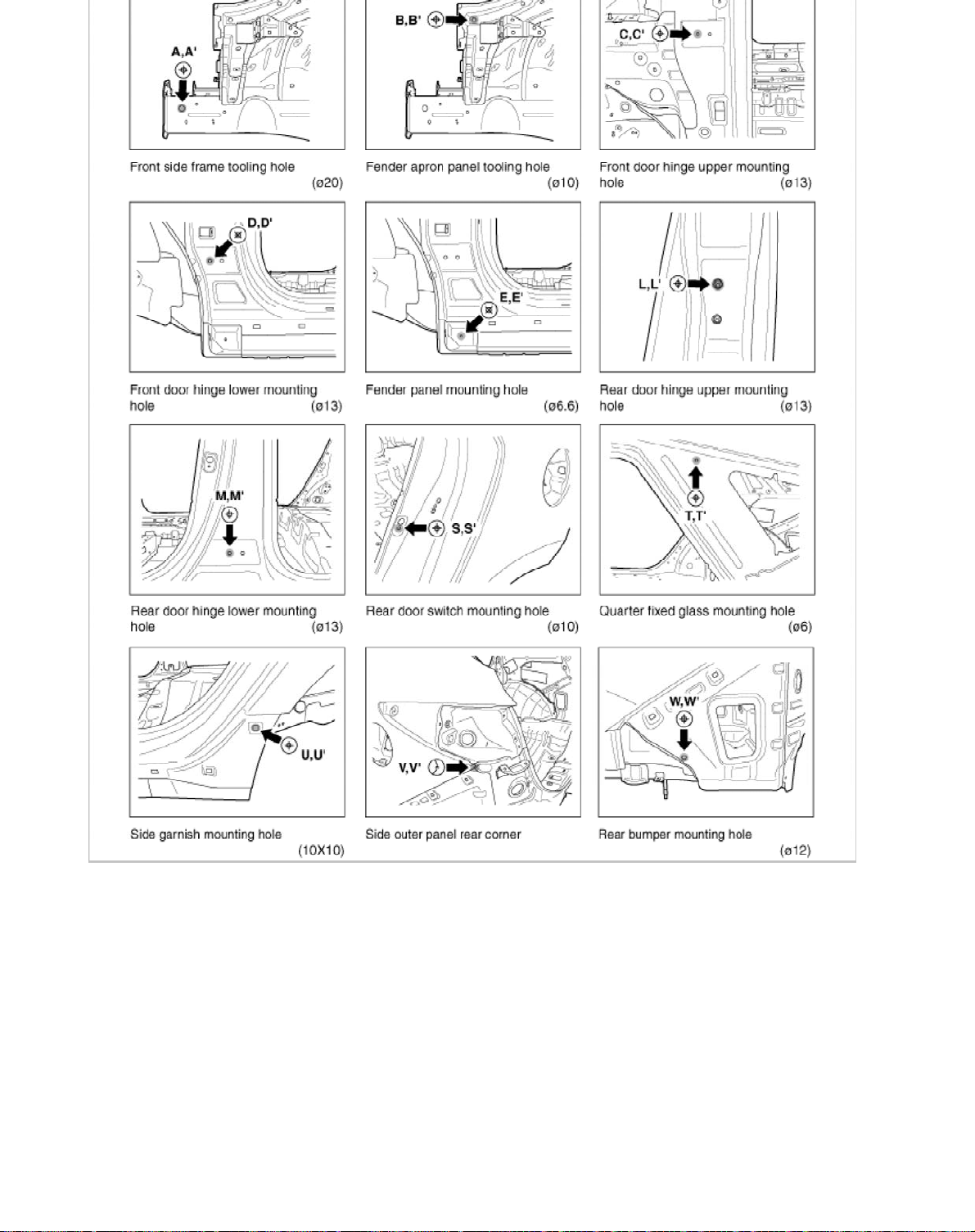
Side body B
3
Page 62
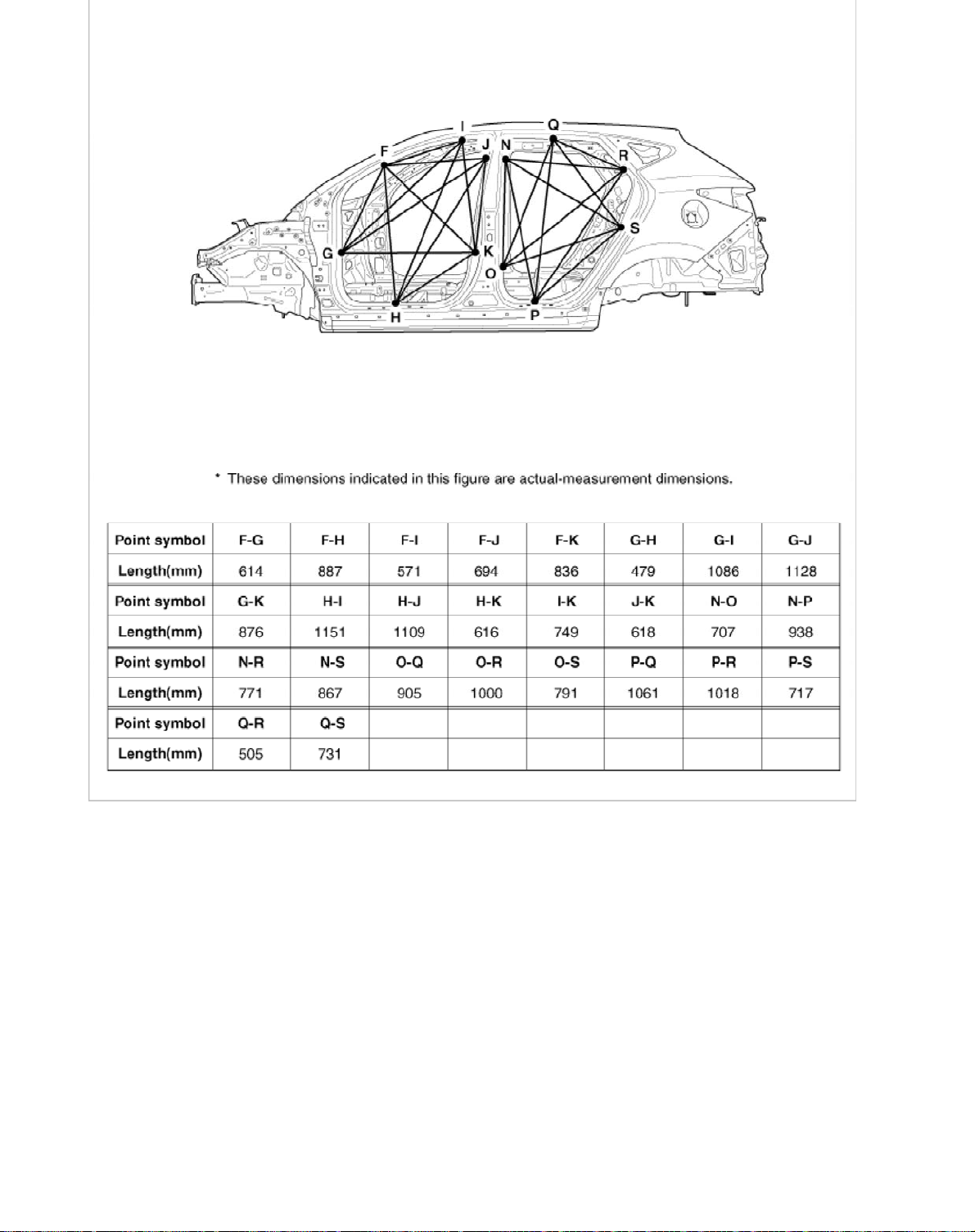
4
Page 63
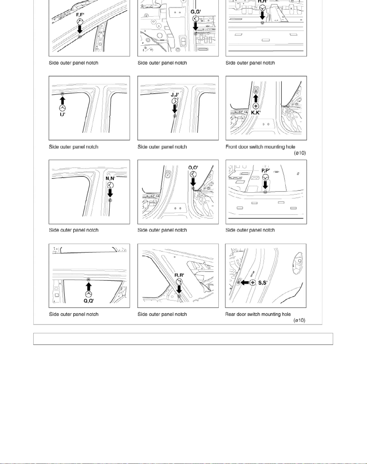
Body (Interior and Exterior) > Body Dimensions > Interior > Body Repair
A
5
Interior
Page 64
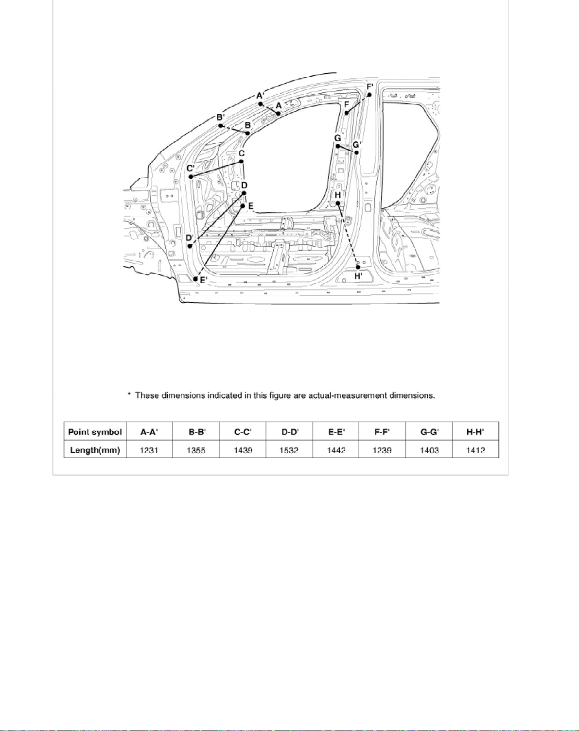
6
Page 65
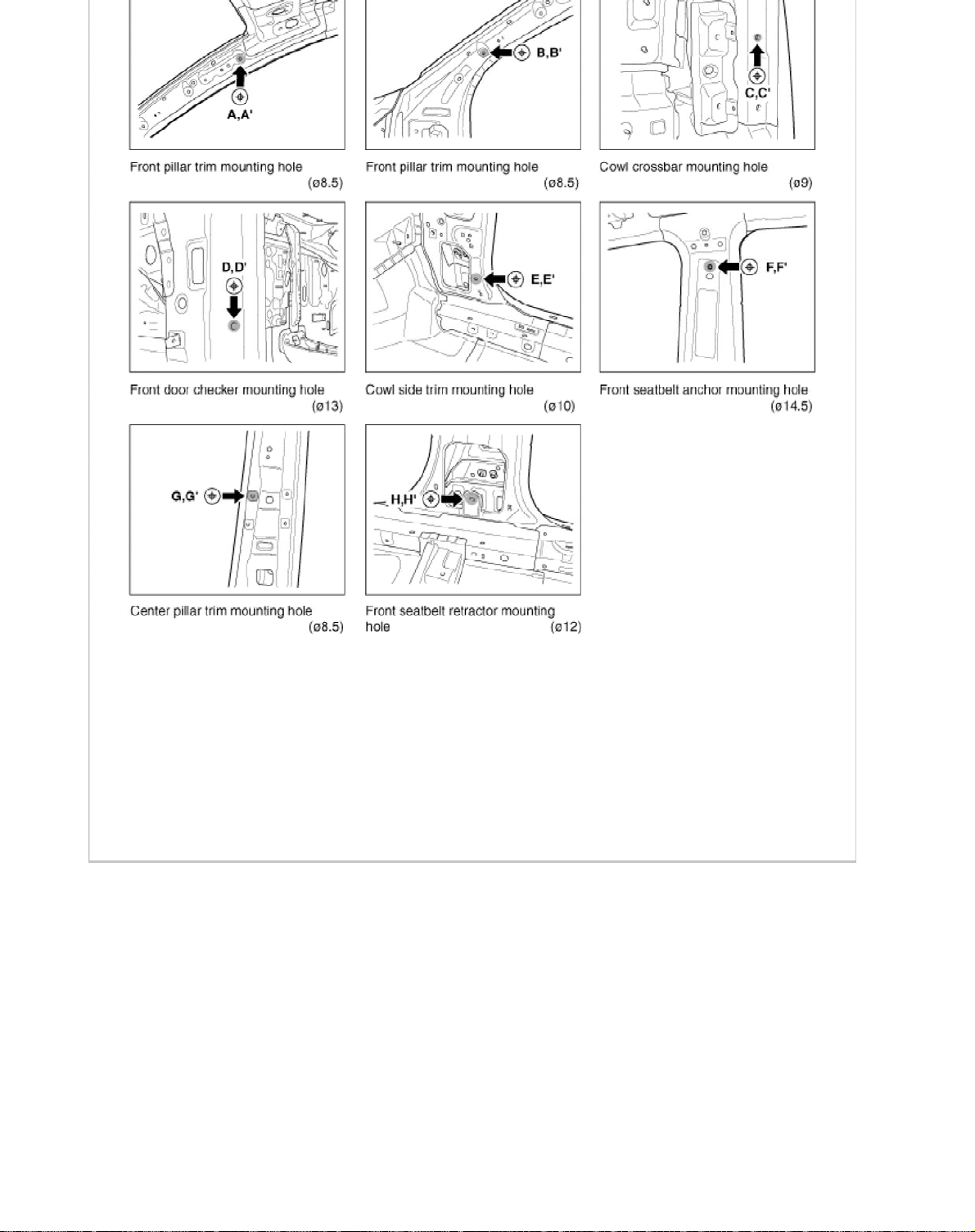
Interior B
7
Page 66
Page 67
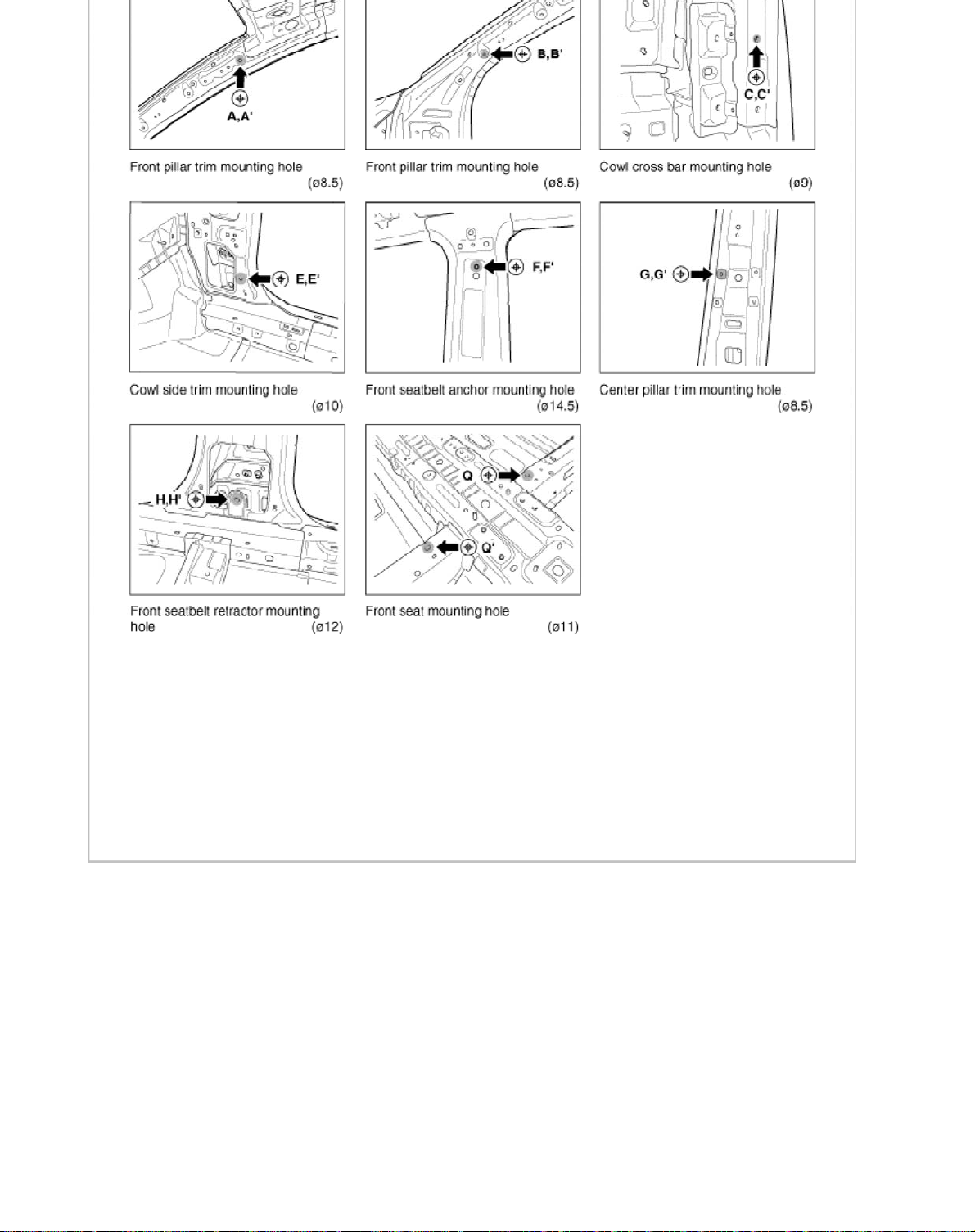
Interior C
9
Page 68
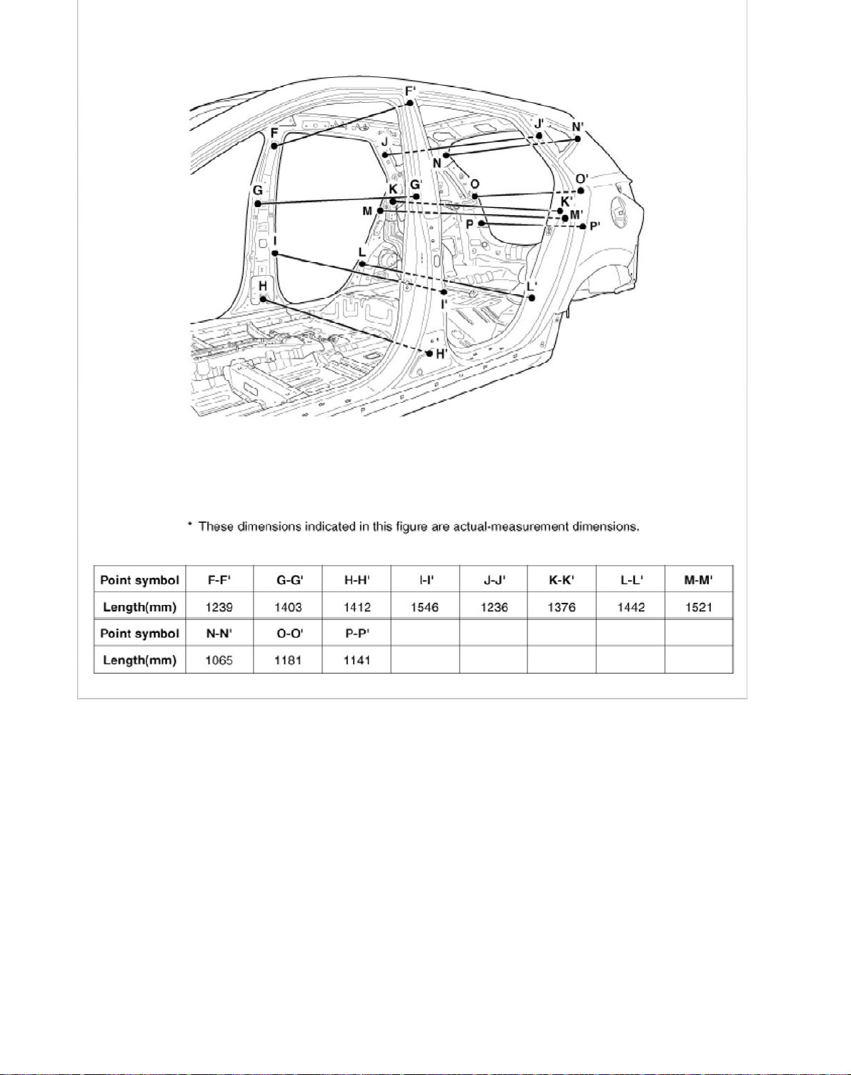
Page 69
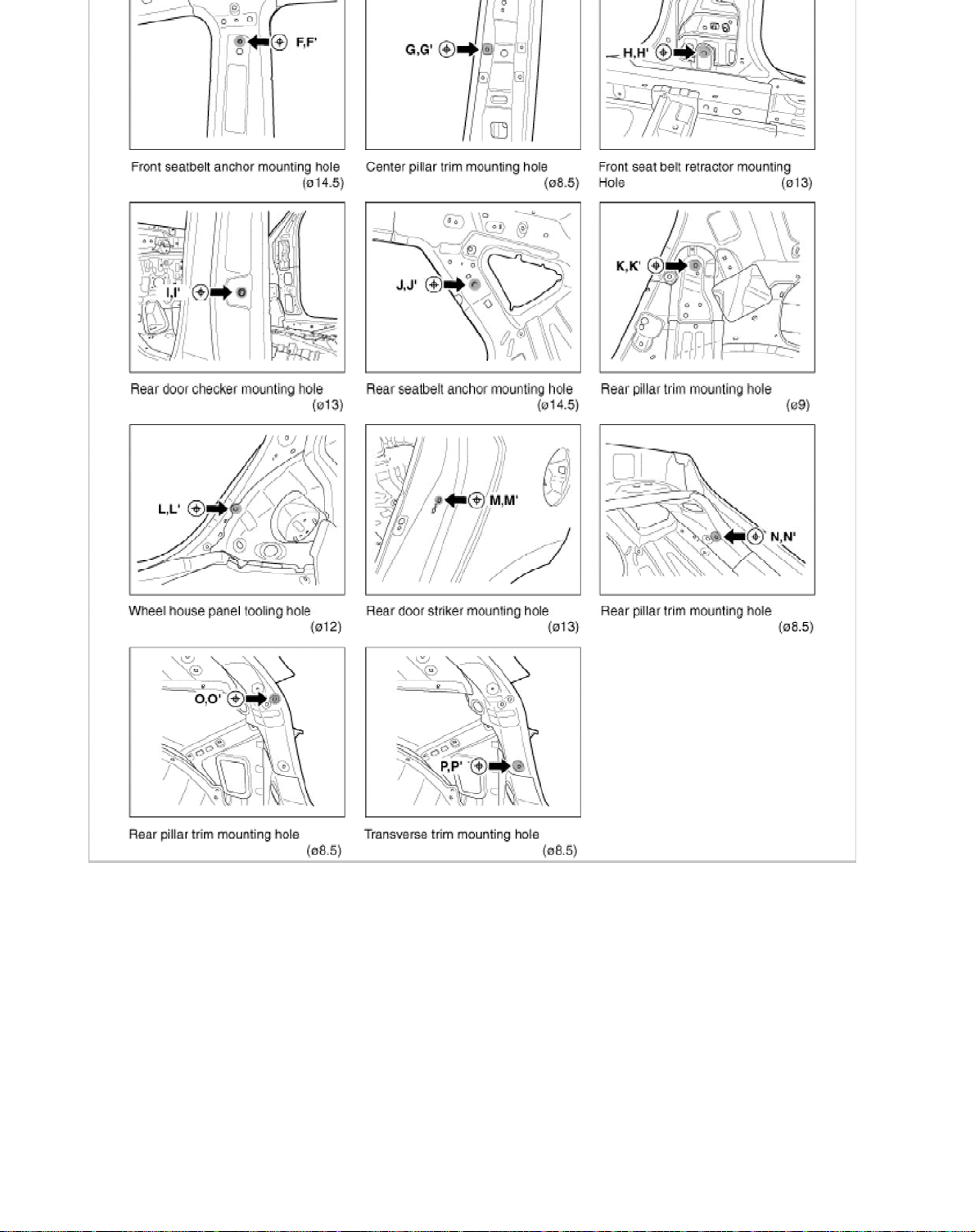
Interior D
Page 70
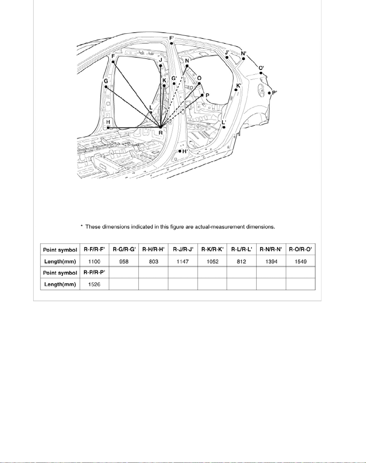
2
Page 71
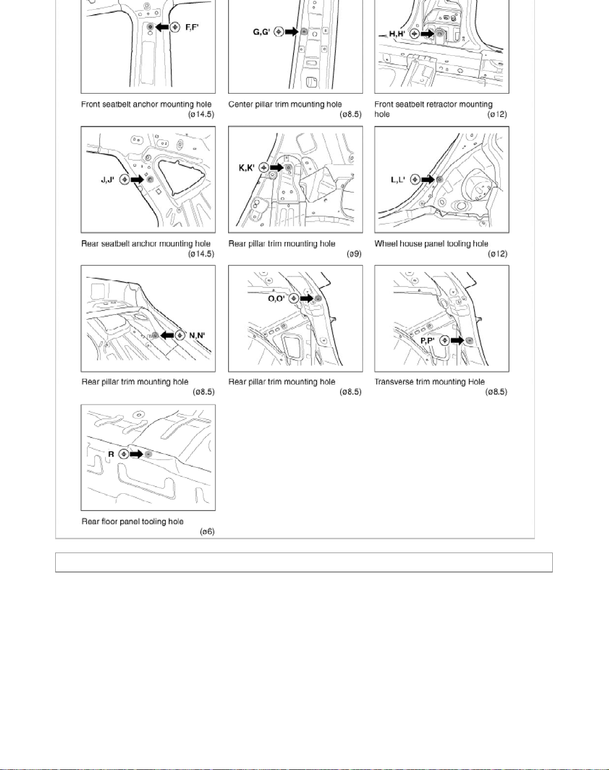
Body (Interior and Exterior) > Body Dimensions > Rear Body > Body Repair
3
Page 72
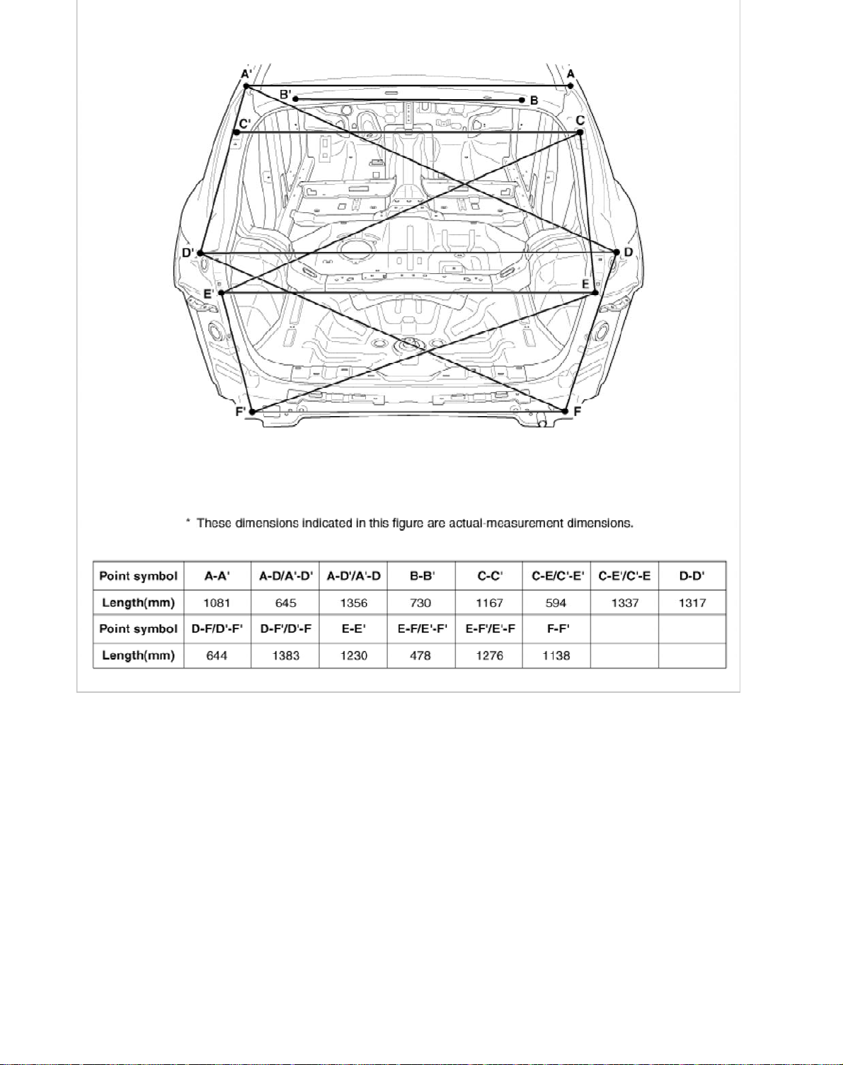
4
Page 73

Body (Interior and Exterior) > Body Dimensions > Under Body > Body Repair
j
s
5
Pro
ected Dimension
Page 74
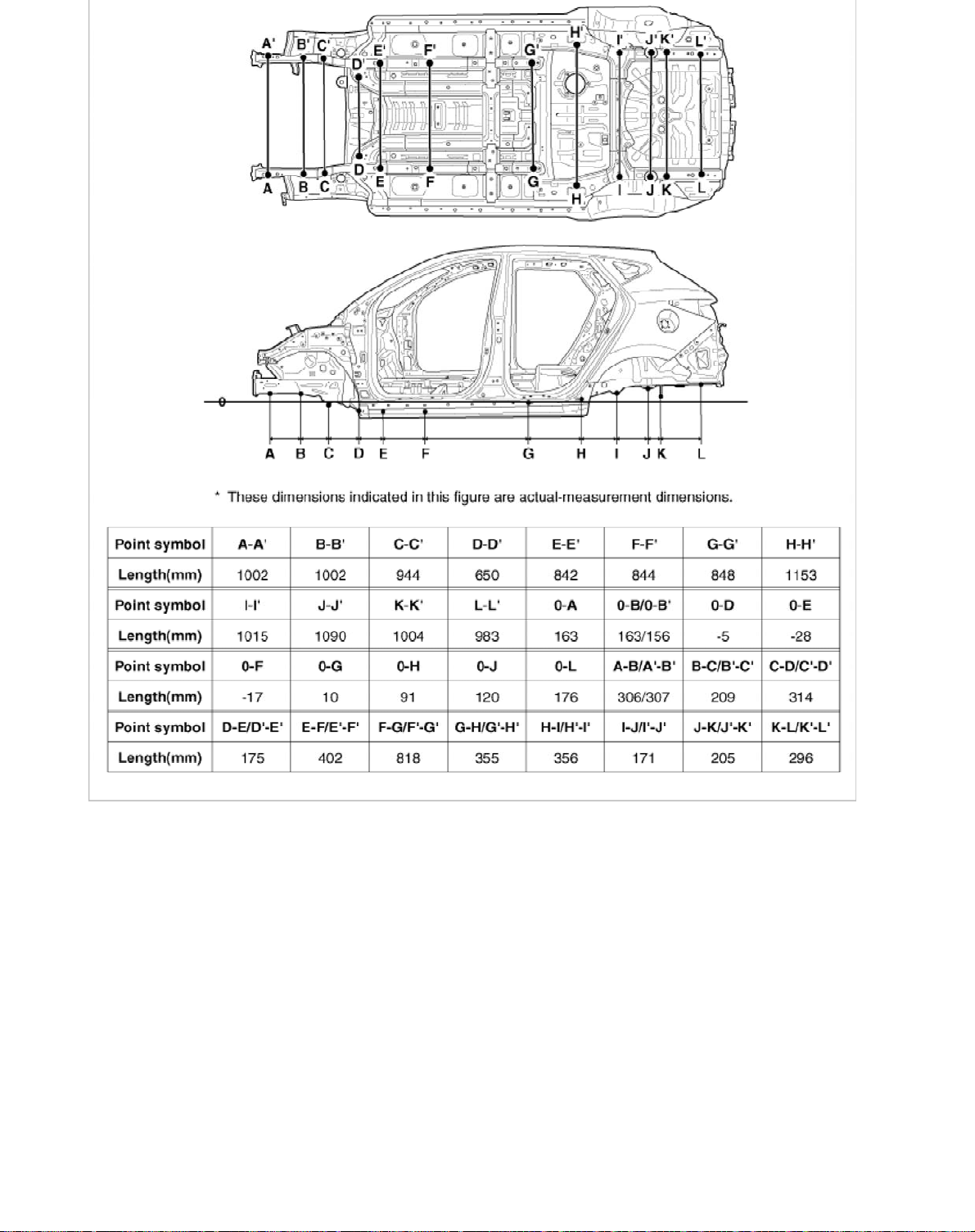
6
Page 75
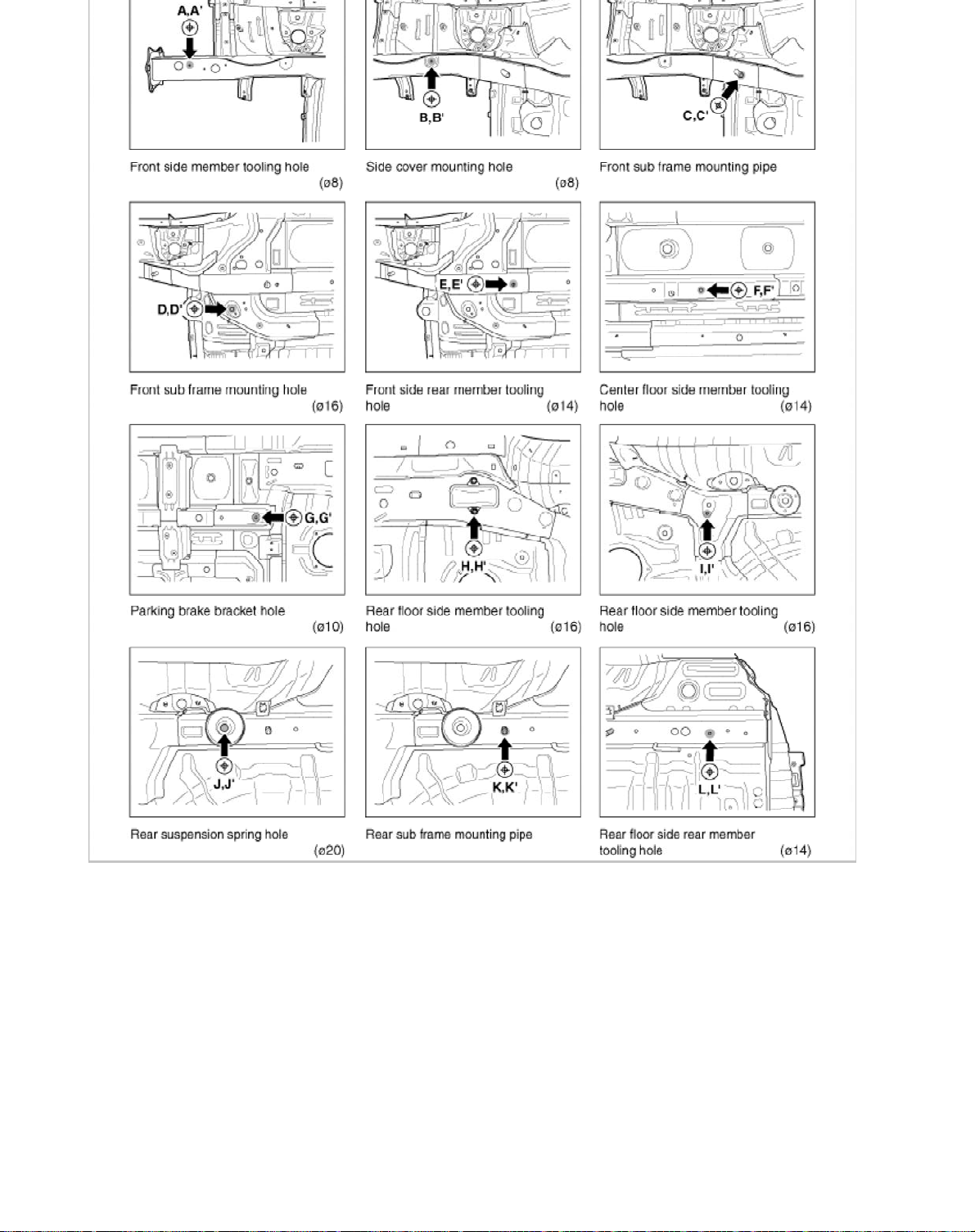
Actual- Measurement Dimension
s
7
Page 76
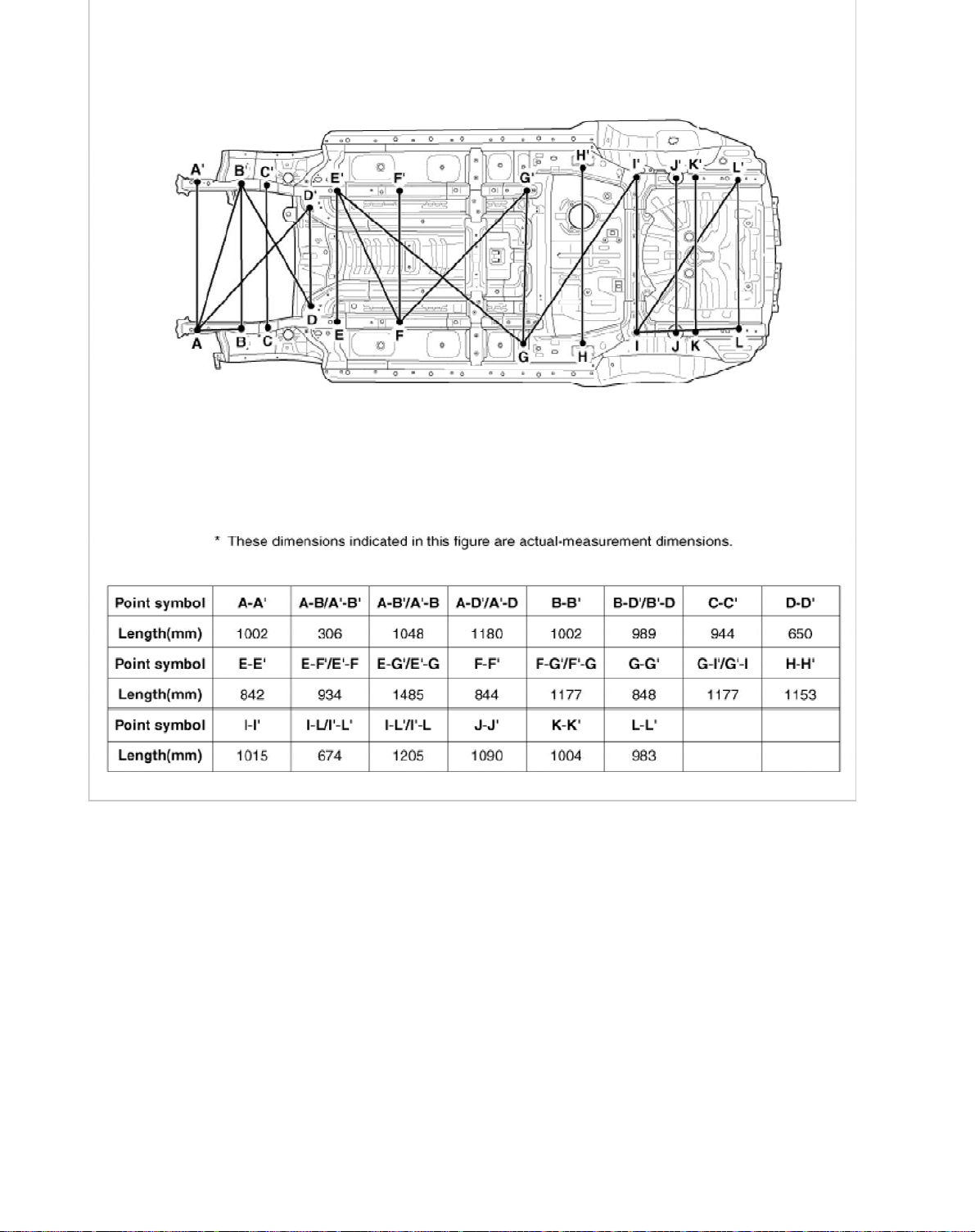
Page 77
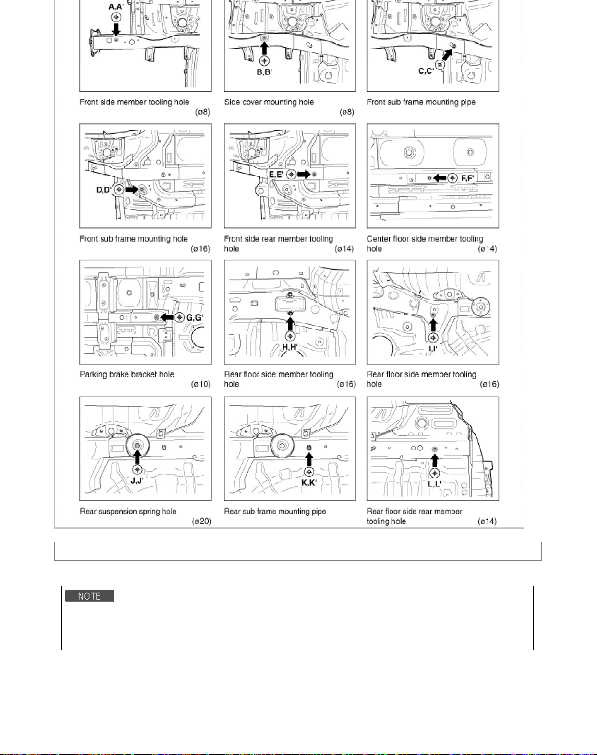
Body (Interior and Exterior) > Exterior > Fender > Repair procedures
9
Replacement
• When removing and installing the hood, an assistant is necessary.
• Be careful not to damage the hood and body.
• When removing the clips, use a clip remover.
1. Remove the front bumper.
(Refer to the BD group – “Front Bunper” )
2. Loosen the mud guard mounting screws.
Page 78
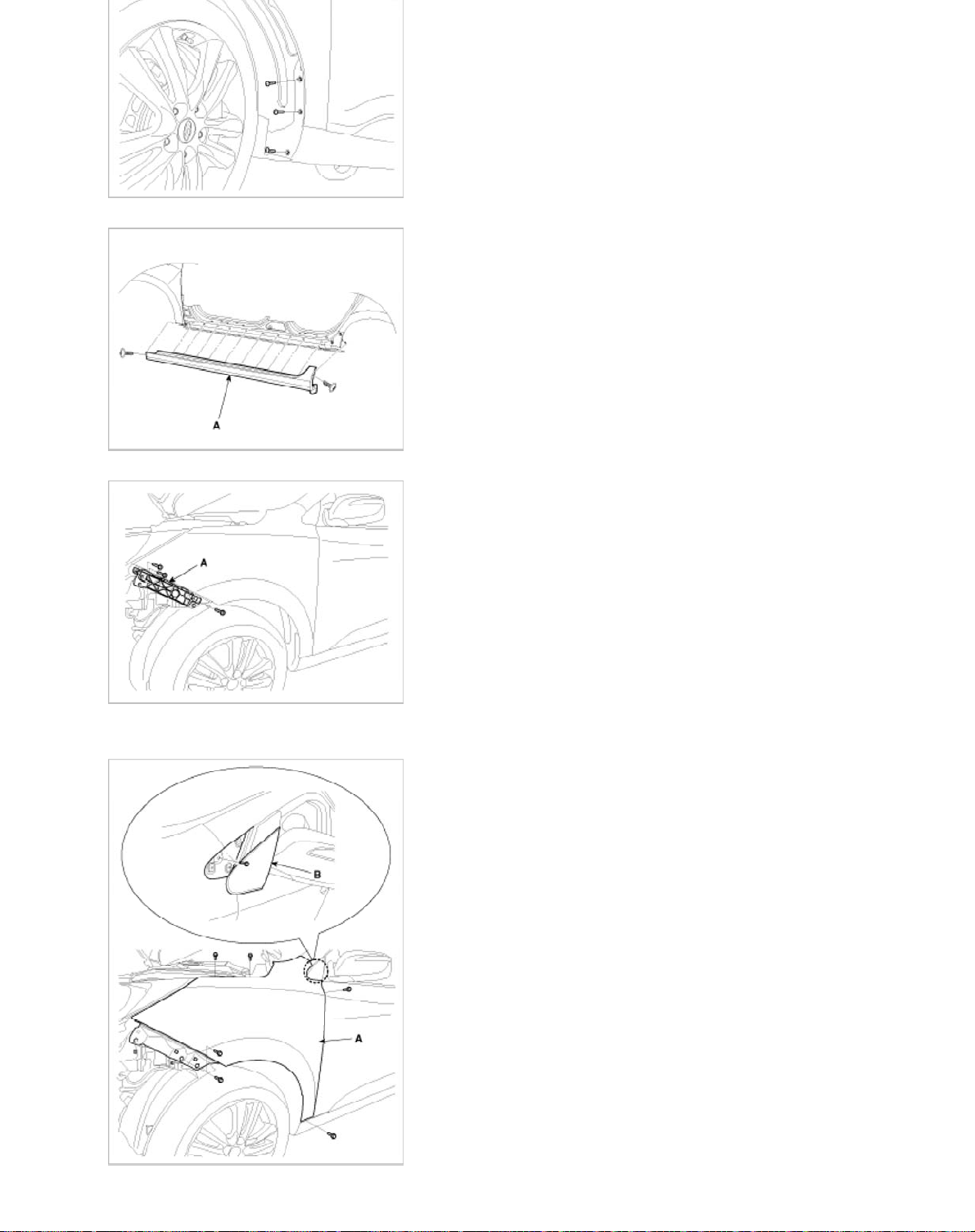
3. After loosening the mounting screws and clips, then remove the side sill garnish (A).
4. After loosening the mounting screws, then remove the front bumper side mounting bracket (A).
5. Using a screwdriver, remove the fender side cover (B).
6. After loosening the mounting bolts, then remove the fender (A).
Page 79
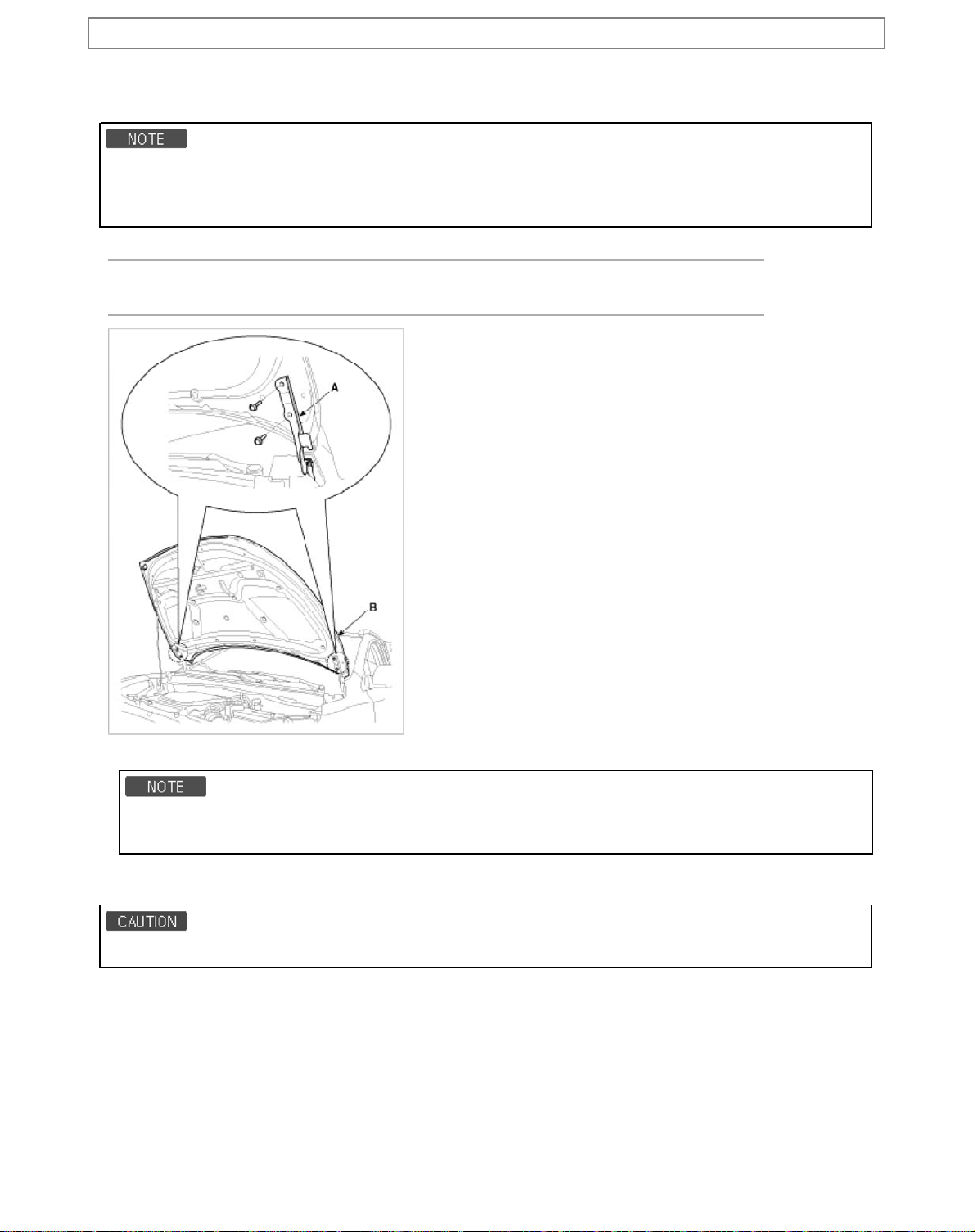
Body (Interior and Exterior) > Exterior > Hood > Repair procedures
p
Re
lacement
Hood Assembly Replacement
• When removing and installing the hood, an assistant is necessary.
• Take care not to damaged the hood and body.
• When removing the clips, use a clip remover.
1. Loosen the hood hinge (A) mounting bolts, remove the hood (B).
Tightening torque:
21.6 ~ 26.5 N.m (2.2 ~ 2.7 kgf.m 15.9 ~ 19.5 lb-ft )
2. Installation is the reverse of removal.
• Make sure the hood locks/ unlocks and opens/ closes properly.
• Adjust the hood alignment.
Hood Insulator Pad Replacement
• Take care not to scratch the hood panel.
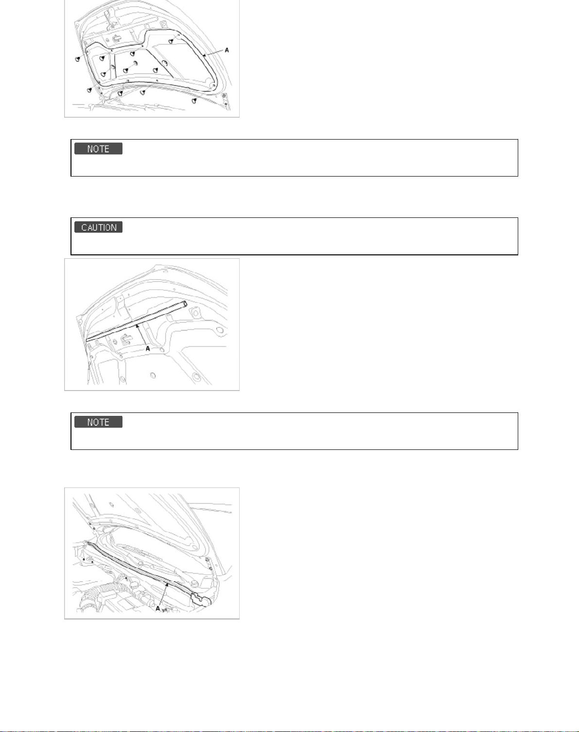
1. Using a clip remover, remove the clips.
2. Remove the hood insulator pad (A).
Page 80
3. Installation is the reverse of removal.
2
• Replace any damaged clips.
Hood Seal Weatherstrip Replacement
1. Detach the clips, then remove the hood weatherstrip(A).
• Take care not to scratch the hood seal weatherstrip.
2. Installation is the reverse of removal.
• Replace any damaged clips.
Hood Weatherstrip Replacement
1. Remove the hood weatherstrip (A).
2. Installation is the reverse of removal.
Hood Latch Release Handle Replacement
1. Remove the hood release handle (A).
Page 81
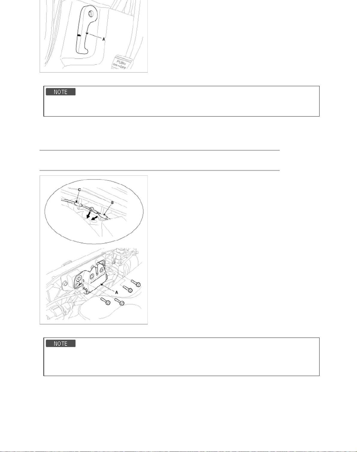
2. Installation is the reverse of removal.
d
3
• Make sure the hood latch release cable is connected properly.
• Make sure the hood locks/unlocks and opens/closes properly.
Hood Latch Replacement
1. Loosen the hood latch (A) mounting bolts.
2. Disconnect the hood latch cable (B) and release cable (C).
Tightening torque :
7.8 ~ 11.8 N.m (0.8 ~ 1.2 kgf.m, 5.8 ~ 8.7 lb-ft)
3. Installation is the reverse of removal.
• Make sure the hood latch release cable is connected properly.
• Make sure the door locks/unlocks and opens/closes properly.
• Adjust the latch alignment.
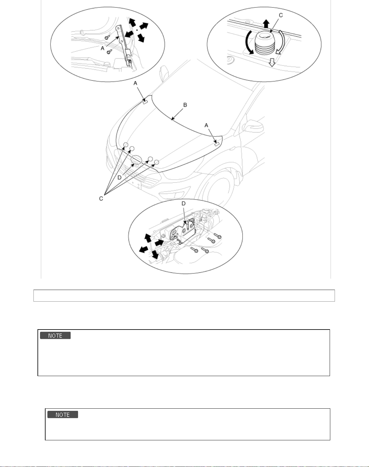
Adjustment
Adjust Hoo
1. After loosening the hinge (A) mounting bolt, adjust the hood (B) by moving it up or down, or right or left.
2. Adjust the hood height by turning the hood over slam bumpers (C).
Page 82
Body (Interior and Exterior) > Exterior > Tail Gate > Repair procedures
4
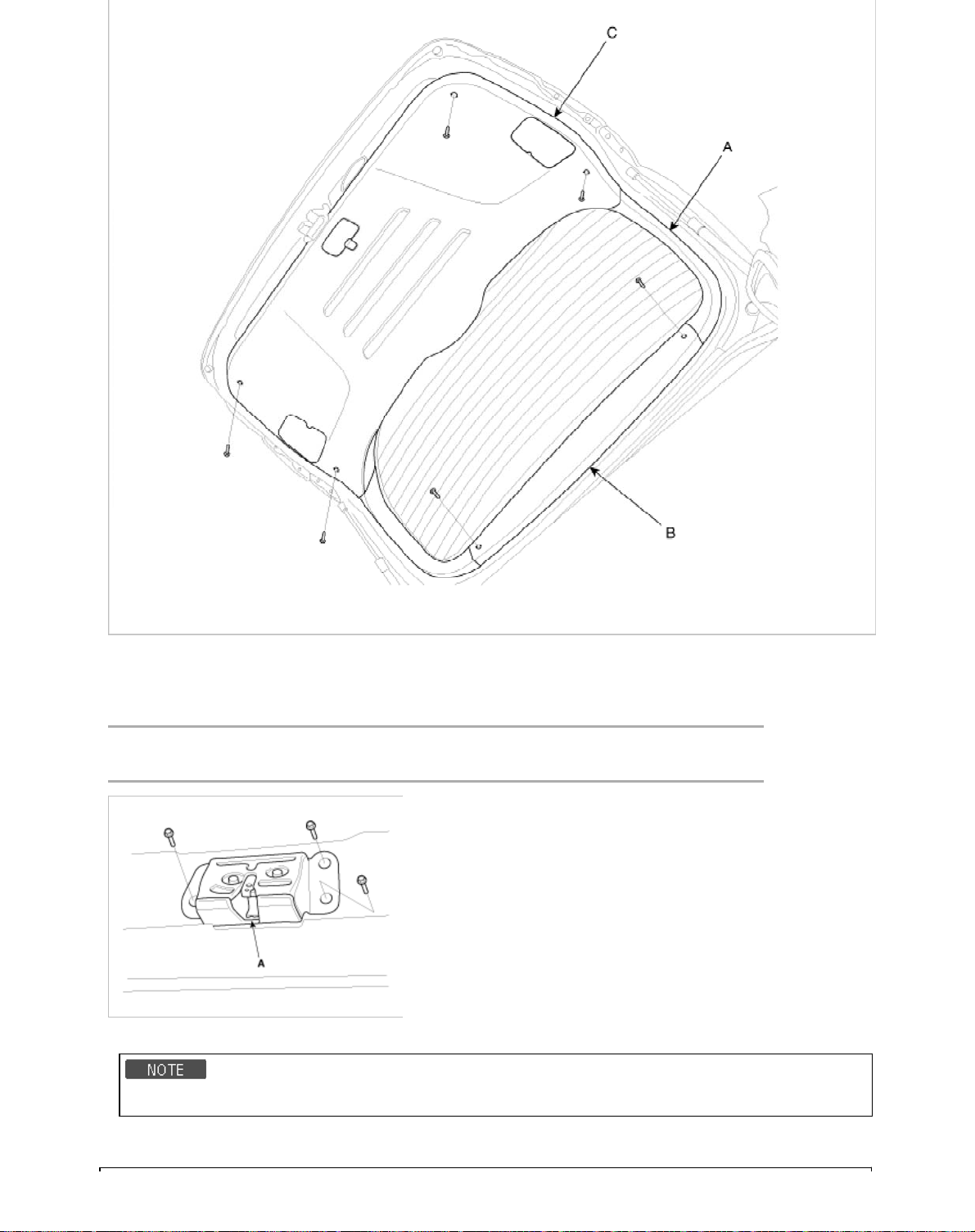
Replacement
Tail Gate Trim Replacement
• When prying with a flat-tipped screwdriver, wrap it with protective tape, and apply protective tape around the related
parts, to prevent damage.
• Put on gloves to protect your hands.
• Make sure the tailgate locks/unlocks and opens/closes properly.
1. Remove the upper trim(B).
2. After loosening the mounting screws, then remove the tailgate trim (C) and side trim(A).
3. Installation is the reverse of removal.
• Replace and damaged clips.
• Make sure the opens securely
Page 83
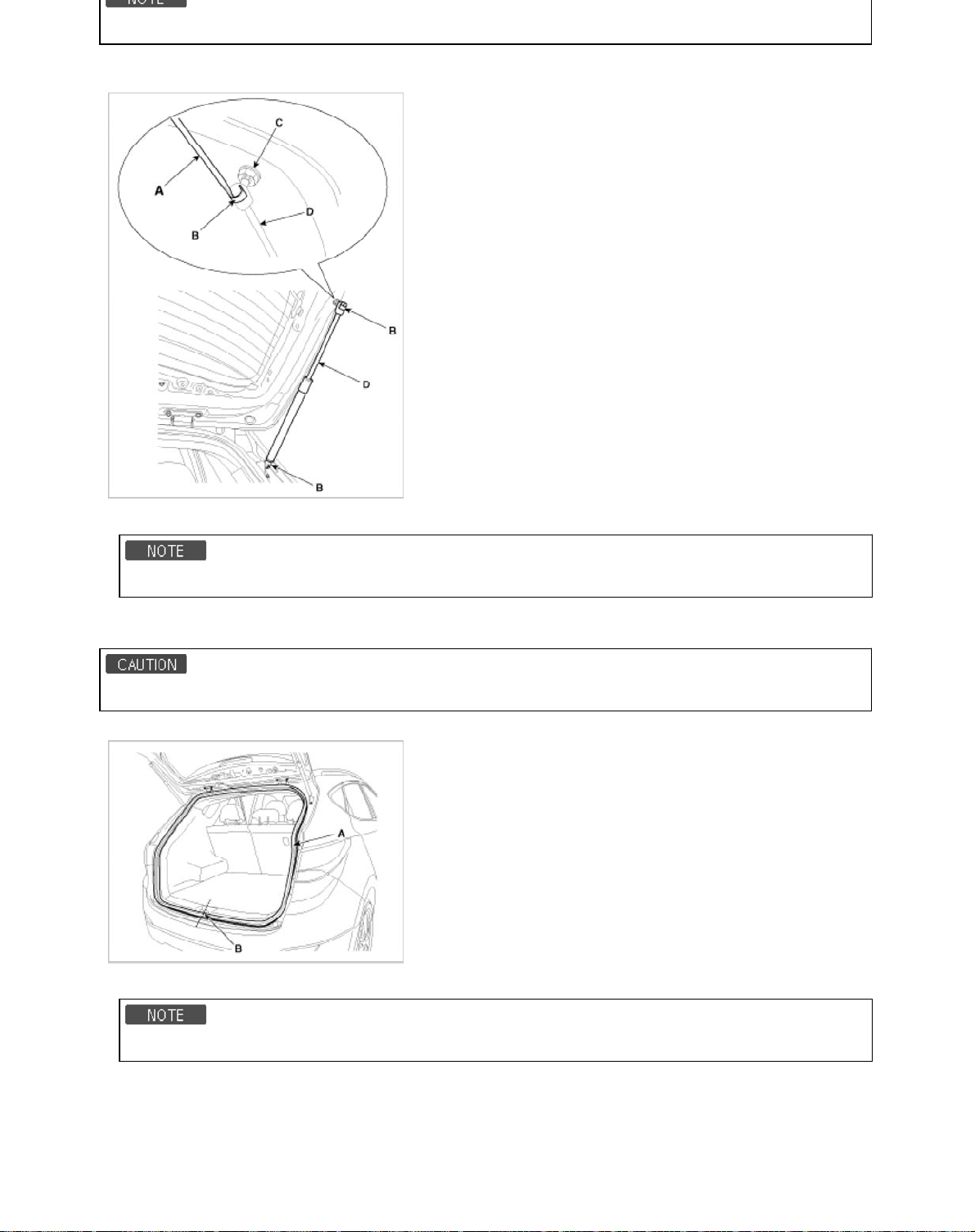
Tail Gate Latch Replacement
5
1. Remove the tail gate trim.
2. After loosening the mounting bolts, then remove the latch assembly (A).
Tightening torque :
6.9 ~ 10.8 N.m (0.7 ~ 1.1 kgf.m, 5.1 ~ 8.0 lb-ft)
3. Installation is the reverse of removal
• Make sure the tail gate opens properly.
Tail Gate Lift Replacement
Page 84
• Take care not to be closed the tail gate, when removing the life.
6
1. Using a screwdriver (A), lift the socket clip (B) up slightly on both ends of the lifter (D), and then remove the lifter from the
bracket (C).
2. Push the socket of the lifter into the bracket for installation.
• Make sure the tailgate locks/unlocks and opens/closes properly.
Tail Gate weatherstrip Replacement
• Do not apply sealant to the body.
1. Remove the tail gate weatherstrip (A).
2. Installation is the reverse of removal.
• Install the weatherstrip aligned with canter line (B).
Adjustment
1. Check that the door and body edges are parallel.
2. After loosening the tailgate hinge (A) mounting bolt, adjust the tailgate by moving it up or down, or right or left.
Page 85
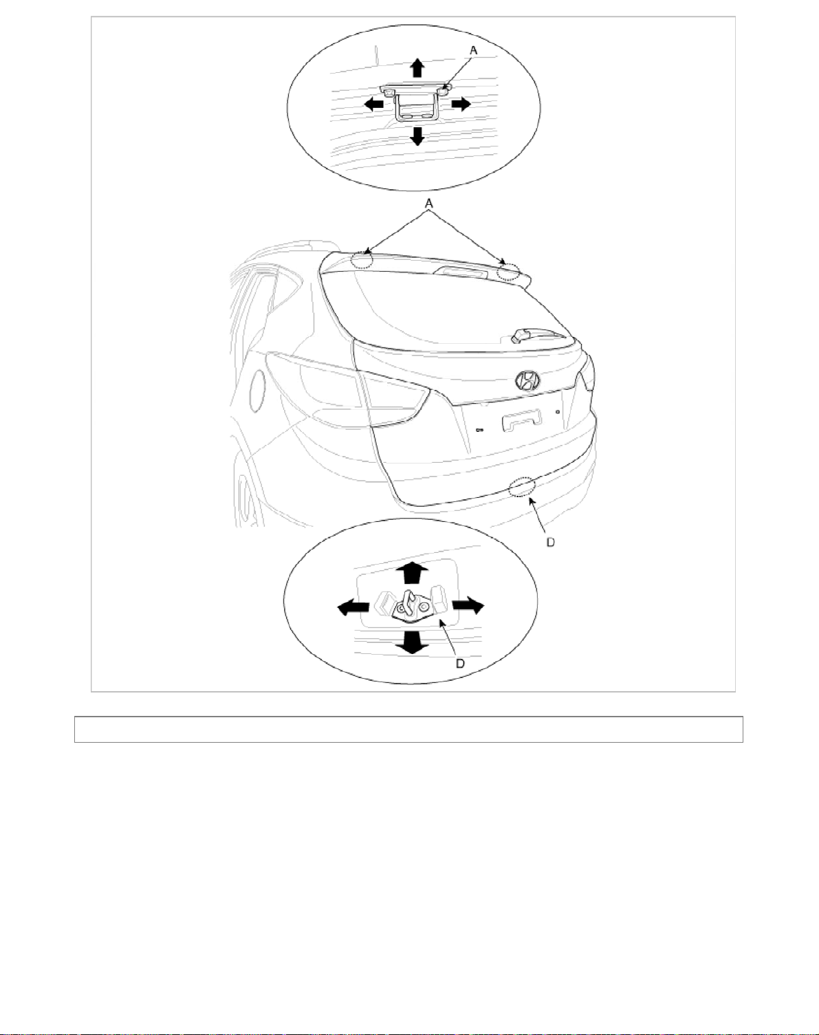
4. Make sure the trunk lid opers and locks securely.
p
7
Body (Interior and Exterior) > Exterior > Front Door > Components and Components Location
Com
onents
Page 86
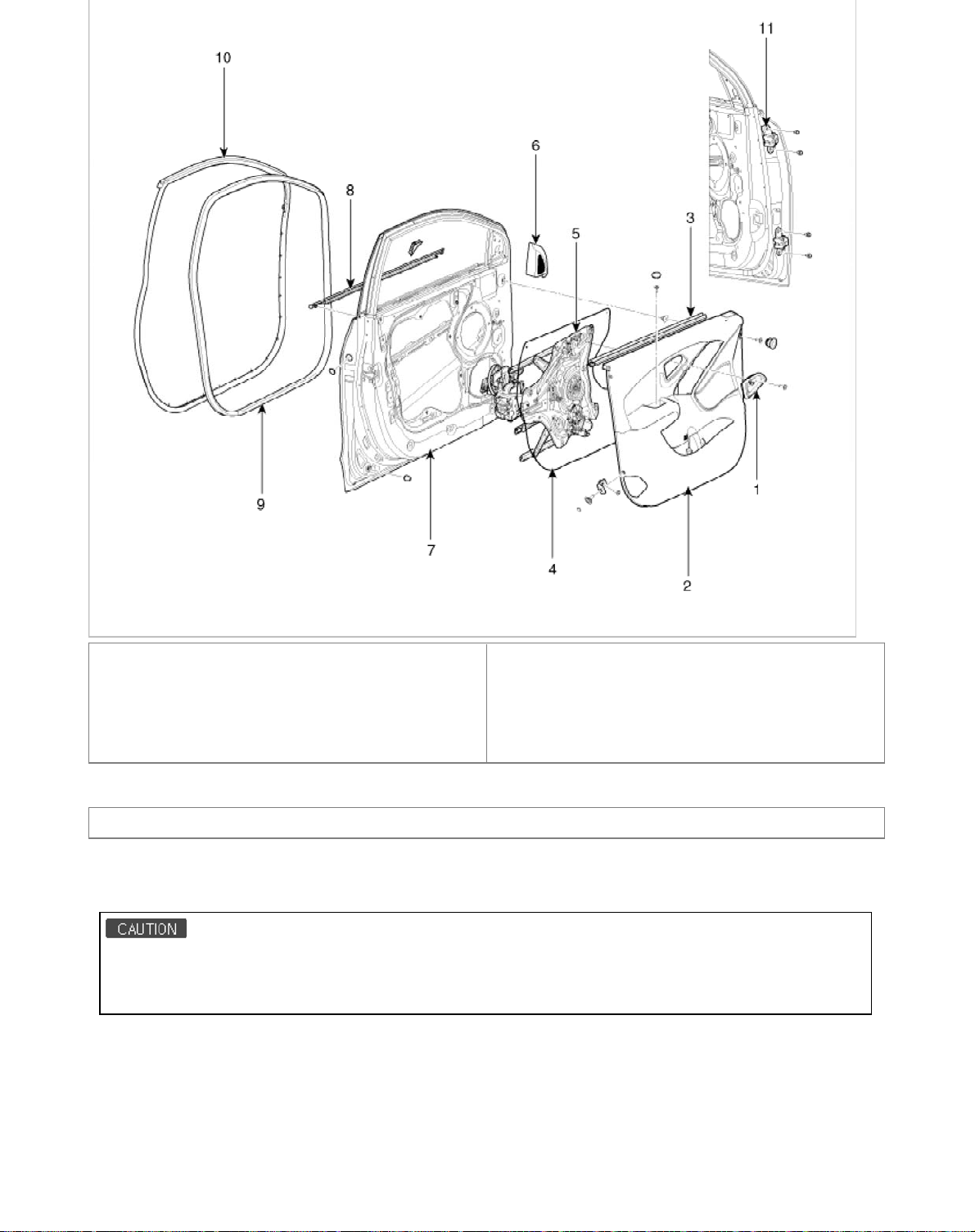
1.Door inside handle housing
p
2. Door trim
3. Door belt inner weatherstrip
4. Door screen
5. Door module
6. Quadrant inner cover
7. Door panel
8. Door belt outside weatherstrip
9. Door side weatherstrip
10. Body side weatherstrip
11. Door hinge
Body (Interior and Exterior) > Exterior > Front Door > Repair procedures
Re
lacement
Front Door Trim Replacement
• When prying with a flat-tipped screwdriver, wrap it with protective tape, and apply protective tape around the related
parts, to prevent damage.
• Put on gloves to protect your hands.
1. Using a screwdriver or remover, remove the quadrant inner cover (A).
2. Disconnect the tweeter speaker connector (B).
Page 87
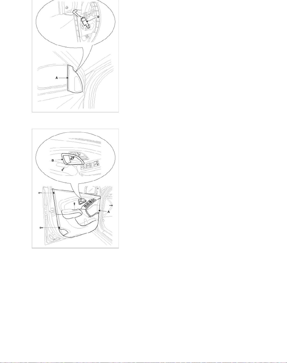
3. After loosening the mounting screws, then remove the door inside handle housing (B).
9
4. After loosening the mounting screws, then remove the door trim (A).
5. Push the lock pin (A), disconnect the connectors (B).
Page 88
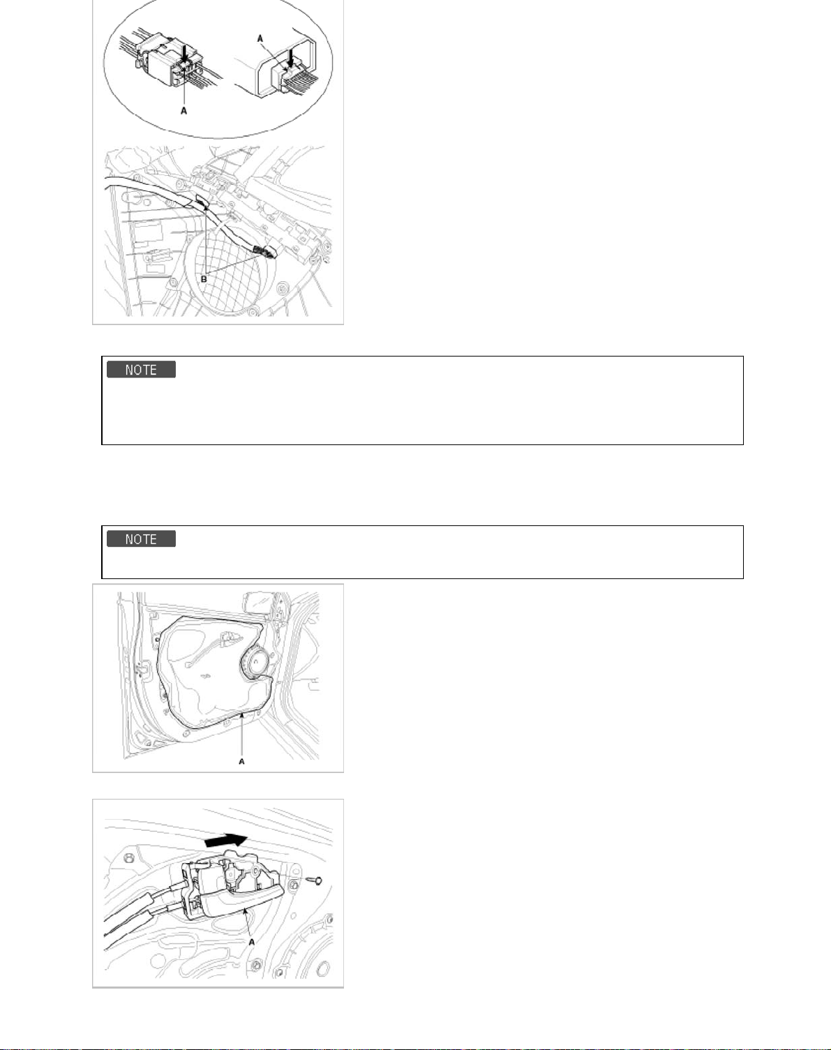
6. Installation is the reverse of removal.
• Make sure connectors are connected properly and each rod is connected securely.
• Make sure the door locks/unlocks and opens/closes properly.
• Replace and damaged clips.
Inside Handle Replacement
1. Remove the door trim.
2. Remove the door screen (A).
• Replace ant damaged screen.
3. After loosening the mounting screws, then remove the inside handle (A).
Page 89
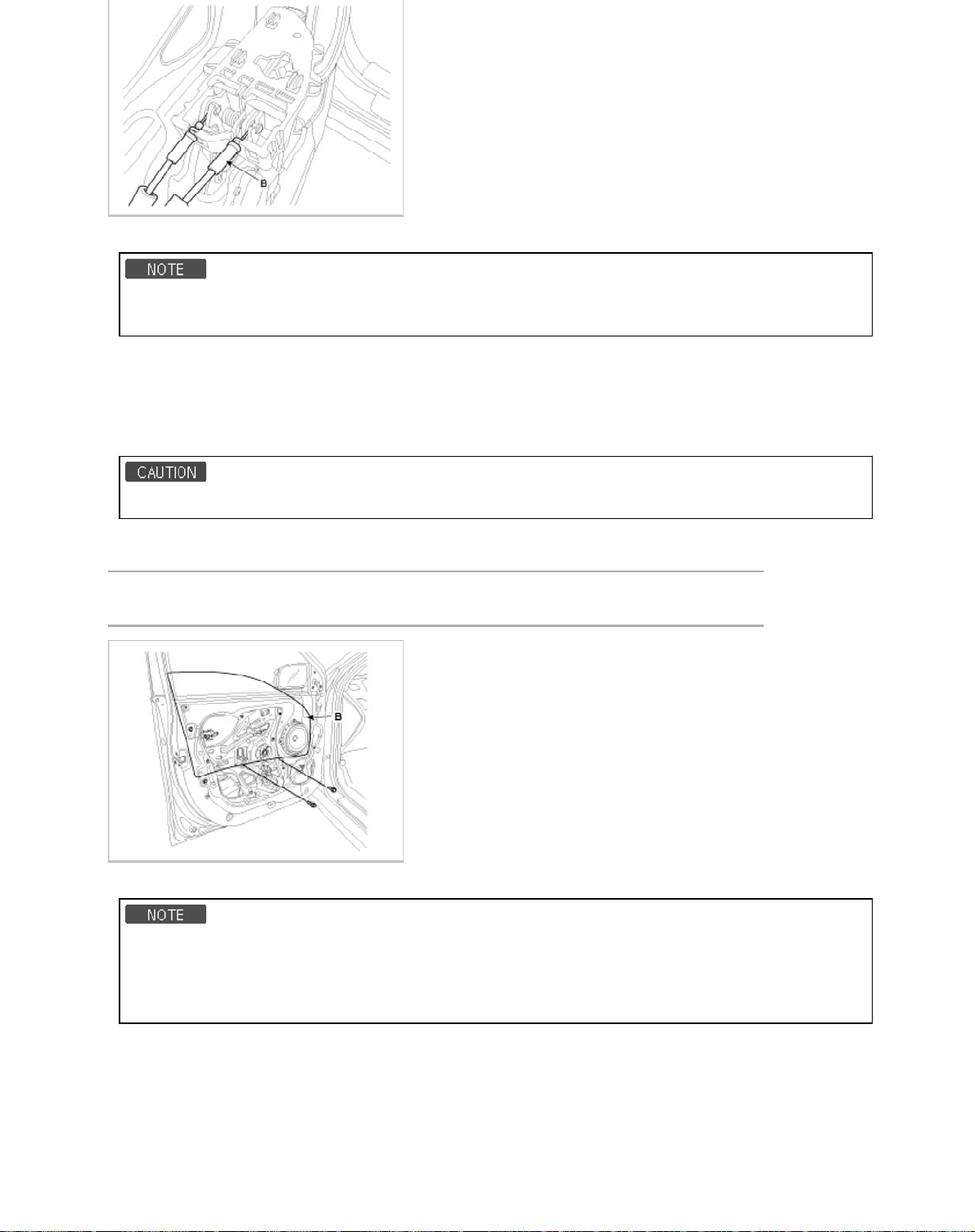
5. Installation is the reverse of removal.
• Make sure the door locks/unlocks and opens/closes properly.
• Replace ant damaged clips.
Glass Replacement
1. Remove the front door trim.
2. Remove the door screen.
3. Remove the glass mounting plug hole.
• Take care not to drop to glass and scratch the glass surface.
4. Carefully adjust the glass (B) until you can see the bolts, then loosen them. Separate the glass from the glass run and
carefully pull the glass out through the window slot.
Tightening torque :
6.9 ~ 10.8 N.m (0.7 ~ 1.1kgf.m 5.1 ~ 8.0 lb-ft )
5. Installation is the reverse of removal.
• Roll the glass up and down to see if it move freely without binding.
• Adjust glass position as needed.
• Replace ant damaged clips.
• Make sure the door locks/unlocks and opens/closes properly.
Speaker Replacement
1. Remove the door trim.
2. Remove the door screen.
3. After loosening the mounting screws, remove the speaker (B).
4. Disconnect the speaker connector (A).
Page 90
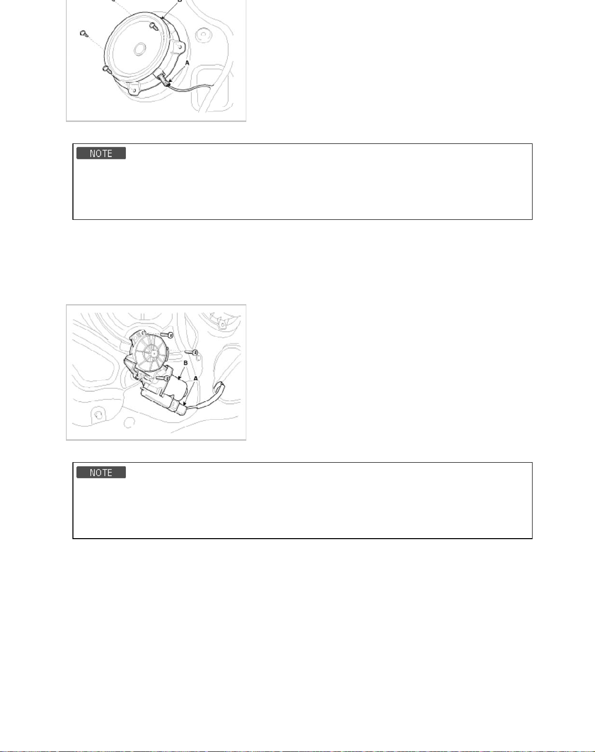
5. Installation is the reverse of removal.
2
• Use sheet metal screws to secure the speaker.
• Replace ant damaged clips.
• Make sure connectors are connected properly and each rod is connected securely.
• Make sure the door locks/unlocks and opens/closes properly.
Power Window Motor Replacement
1. Remove the door trim.
2. Remove the door screen.
3. Disconnect the connector (A), then loosen the mounting screws.
4. Remove the power window motor (B).
5. Installation is the reverse of removal.
• Grease should be applied to areas where there is rotational parts and springs.
• Roll the glass up and down to see if it move freely without binding.
• Replace ant damaged clips.
• Make sure the door locks/unlocks and opens/closes properly.
Door Module Assembly Replacement
1. Remove the following parts :
A. Front door trim
B. Door screen.
C. Window glass
D. Outside handle
2. Loosen the outside handle base mounting screw (A).
Page 91
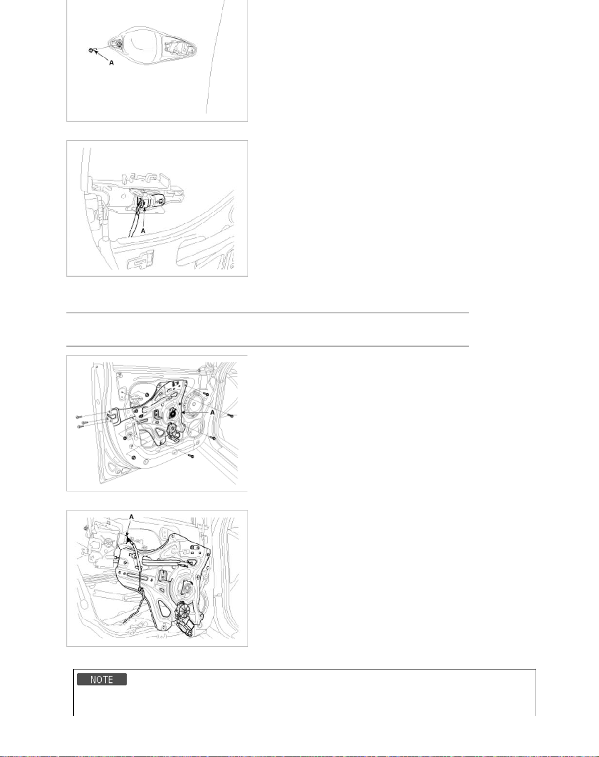
3. Disconnect the outside handle connector (A).
3
4. Loosen the module mounting bolts.
5. Loosen the latch mounting nuts, remove the module (A).
Tightening torque :
6.9 ~ 10.8 N.m (0.7 ~ 1.1 kgf.m, 5.1 ~ 8.0 lb-ft)
6. Disconnect the connector (A) and clip.
7. Installation is the reverse of removal.
• The area of whole parts should be applied with sufficient grease.
Page 92
• Make sure the door locks/unlocks and opens/closes properly.
4
• Replace ant damaged clips.
Outside Handle Replacement
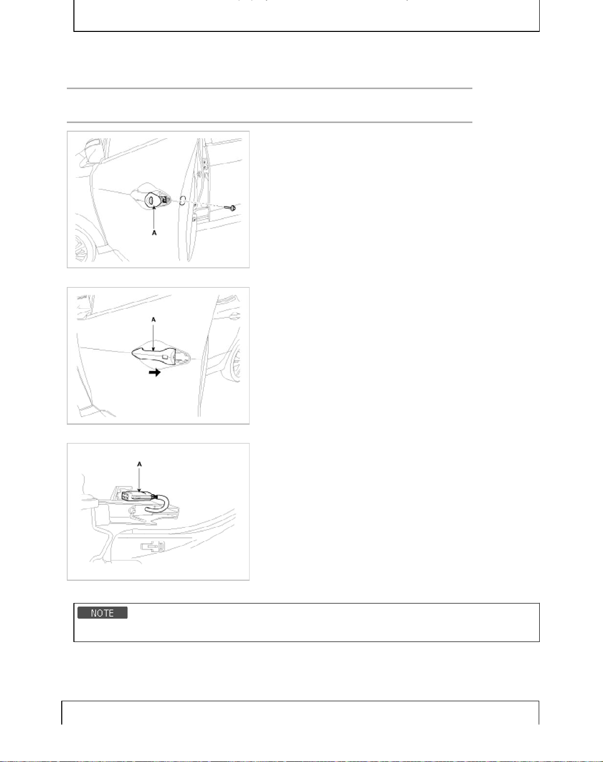
1. Remove the cap, loosen the mounting bolt.
2. Remove the outside handle cover (A).
Tightening torque :
6.9 ~ 10.8 N.m (0.7 ~ 1.1kgf.m 5.1 ~ 8.0 lb-ft )
3. Remove the outside handle (A), by sliding it rearward.
4. Disconnect the outside handle connector (A).
5. Installation is the reverse the removal.
• Make sure the door locks/unlocks and opens/closes properly.
Adjustment
Glass Adjustment
Page 93
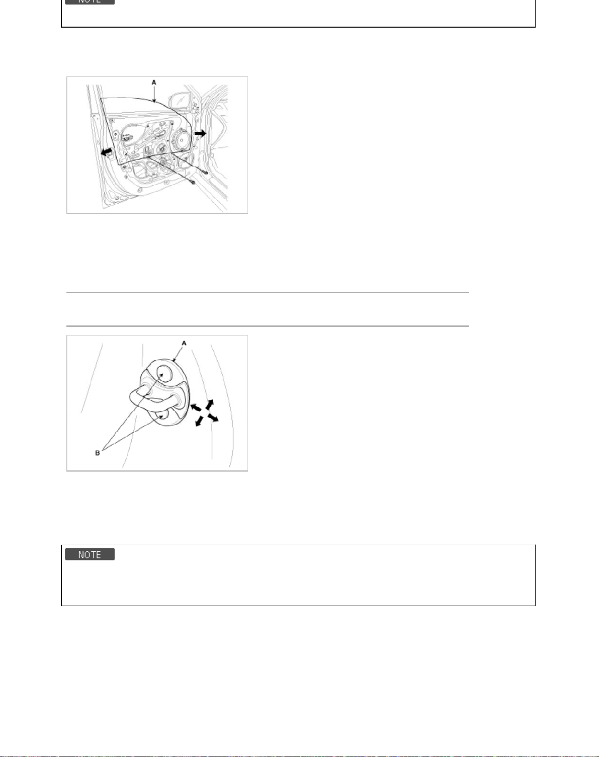
• Check the glass run channel for damage or deterioration, and replace them necessary.
5
1. Remove the door trim.
2. Remove the door screen.
3. Carefully move the glass (A) until the glass mounting bolt are visible, then loosen them.
4. Check that the glass moves smoothly.
Door Striker Adjustment
Make sure the door latches securely without slamming it. If necessary adjust the striker (A): The striker nuts are fixed. The
striker can be fine adjusted up or down, and in or out.
1. Loosen the screws (B) just enough for the striker to move.
Tightening torque (B):
8.8 ~ 13.7 N.m (0.9 ~ 1.4 kgf.m, 6.5 ~ 10.1 lb-ft )
2. Tap on the striker with a plastic hammer to adjust the striker. The striker will not move much, but will give some adjustment.
3. Hold the outer handle out, and push the door against the body to be sure the striker allows a flush fit. If the door latches
properly, tighten the screws and recheck.
Door Position Adjustment
• After installing the door, check for a flush fit with the body, then check for equal gaps between the front, rear, and
bottom, door edges and the body. Check that the door and body edges are parallel. Before adjusting, replace the
mounting bolts.
1. Place the vehicle on a firm, level surface when adjusting the doors.
2. Check that the door and body edges are parallel.
Page 94
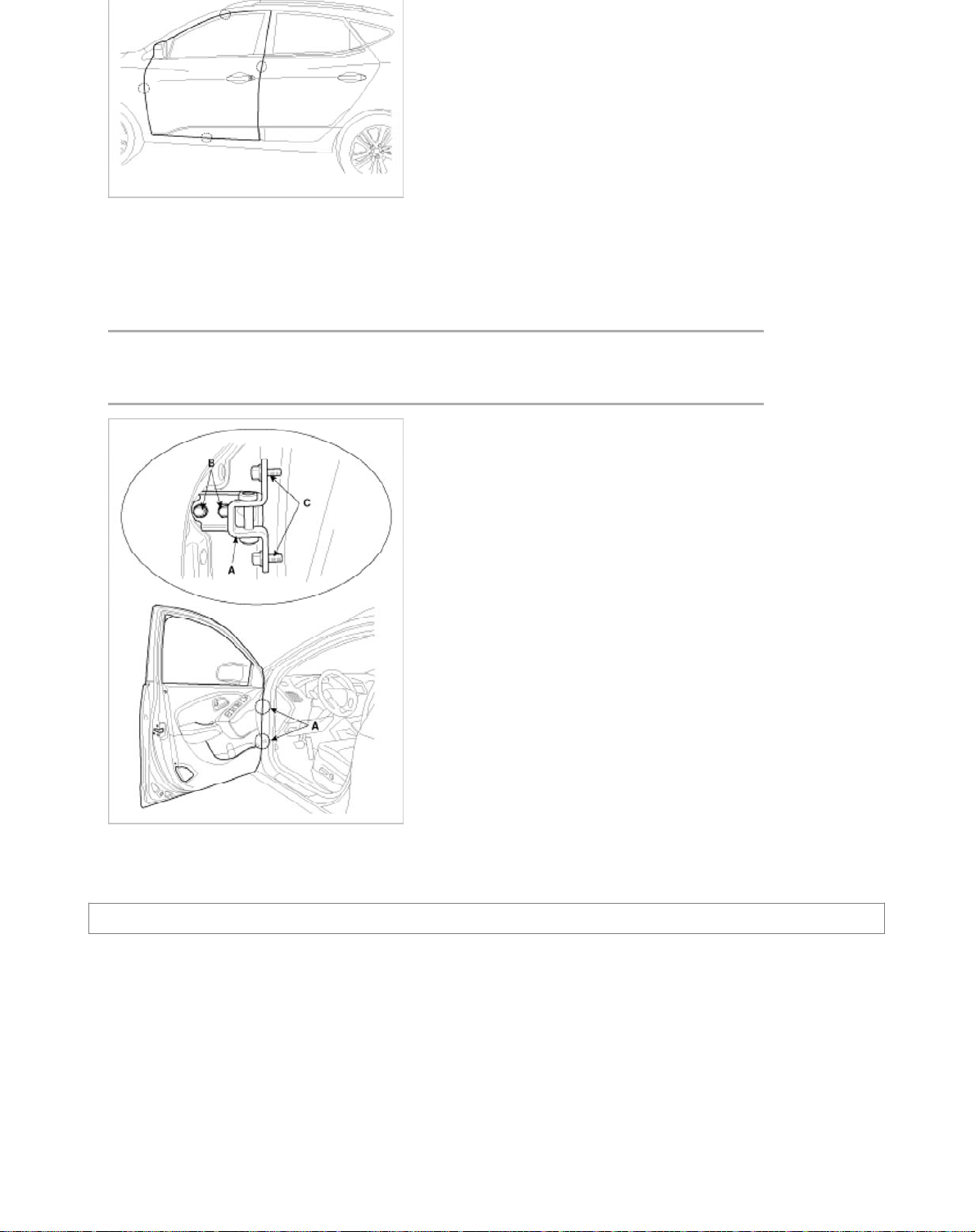
3. Adjust at the hinges (A):
s
6
A. Loosen the door mounting bolts slightly, and move the door IN or OUT until it aligns flush with the body.
B. Loosen the hinge mounting bolts slightly, and move the door backward or forward, up or down as necessary to equalize
the gaps.
C. Place a shop towel on the jack to prevent damage to the door when adjusting the door.
(Special service tool : 09793-21000)
Tightening torque :
(B) : 34.3 ~ 41.2 N.m (3.4 ~ 4.2 kgf.m, 25.3 ~ 30.4 lb-ft)
(C) : 9.8 ~ 19.6 N.m (1.0 ~ 2.0 kgf.m, 7.2 ~ 14.5 lb-ft)
4. Grease the pivot portions of the hinges indicated.
5. Check for water leaks.
Body (Interior and Exterior) > Exterior > Rear Door > Components and Components Location
Component
Page 95
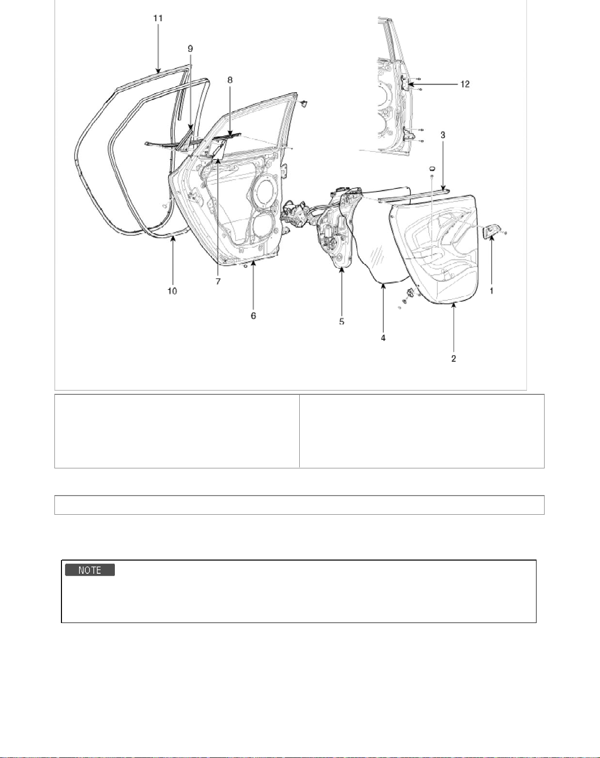
1. Door inside handle housing
7
2. Door trim
3. Door belt inner weatherstrip
4. Door screen
5. Door module
6. Door panel
7. Door delta inner cover
8. Door belt outside weatherstrip
9. Door delta molding cover
10. Door side weatherstrip
11. Body side weatherstrip
12. Door hinge
Body (Interior and Exterior) > Exterior > Rear Door > Repair procedures
Replacement
Door Trim Replacement
• When prying with a flat-tipped screwdriver, wrap it with protective tape, and apply protective tape around the related
parts, to prevent damage.
• Put on gloves to protect your hands.
1. Using a screwdriver or remover, remove the delta inner cover (A).
Page 96
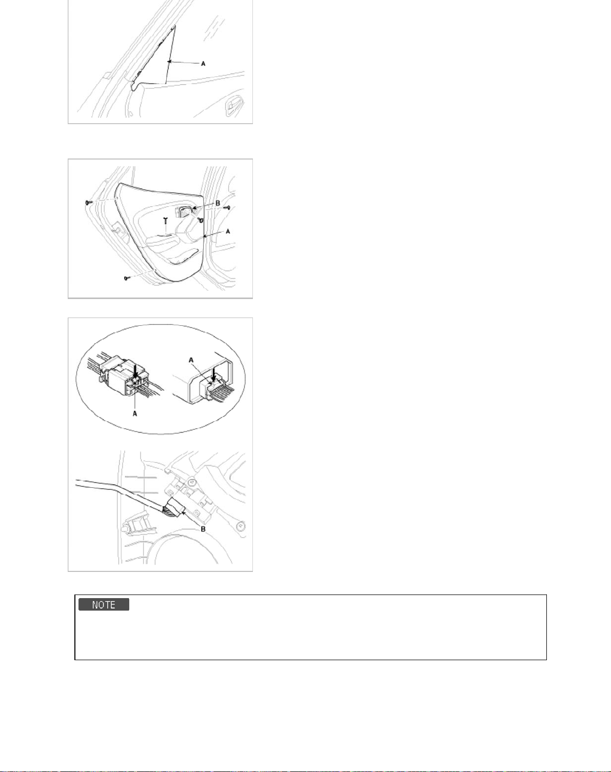
2. After loosening the mounting screw, then remove the door inside handle housing (B).
3. Loosen the mounting screws, then remove the door trim (A).
4. Push the lock pin (A), disconnect the power window connector (B).
5. Installation is the reverse of removal.
• Make sure connectors are connected properly and each rod is connected securely.
• Make sure the door locks/unlocks and opens/closes properly.
• Replace ant damaged clips.
Inside Handle Replacement
1. Remove the door trim.
2. Remove the door screen (A).
Page 97
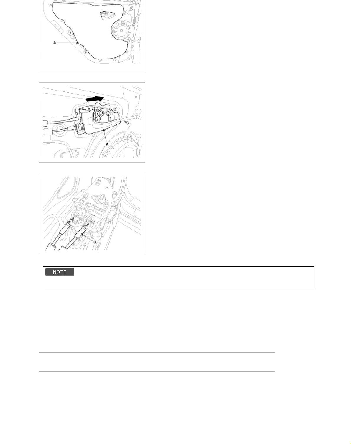
3. After loosening the mounting screws, then remove the inside handle (A).
9
4. Disconnect the inside handle cable (B).
5. Installation is the reverse of removal.
• Make sure the door locks/unlocks and opens/closes properly.
Glass Replacement
1. Remove the following parts.
A. Door trim
B. Door screen
C. Door belt weatherstrip
D. Door delta molding cover
2. After loosening the mounting nuts, then remove the rear channel (A).
Tightening torque :
6.9 ~ 10.8 N.m (0.7 ~ 1.1kgf.m 5.1 ~ 8.0 lb-ft )
Page 98
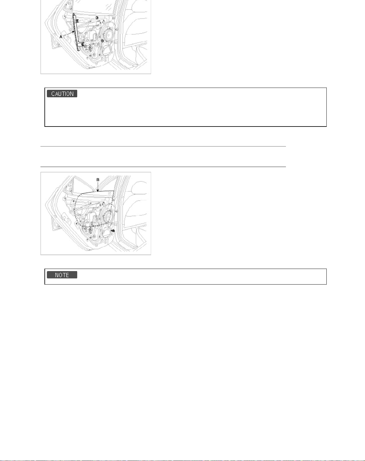
3. Remove the glass mounting plug hole.
• Using the door switch to align the mounting hole with the hole on the door glass.
• If it is impossible, align the hole by hand after removing the motor.
• Be careful not to drop to glass and scratch the glass surface.
4. Carefully adjust the glass (B) until you can see the bolts, then loosen them. Separate the glass from the glass run and
carefully pull the glass out through the window slot.
Tightening torque :
6.9 ~ 10.8 N.m (0.7 ~ 1.1kgf.m 5.1 ~ 8.0 lb-ft )
5. Installation is the reverse the removal.
A. Roll the glass up down to see if it move freely without binding
B. Adjust the position of the glass as needed.
C. Make sure the door locks/unlocks and opens/closes properly.
D. Replace ant damaged clips
Speaker Replacement
1. Remove the door trim.
2. Disconnect the speaker connector (A).
3. After loosening the mounting screws, then remove the speaker (B).
Page 99
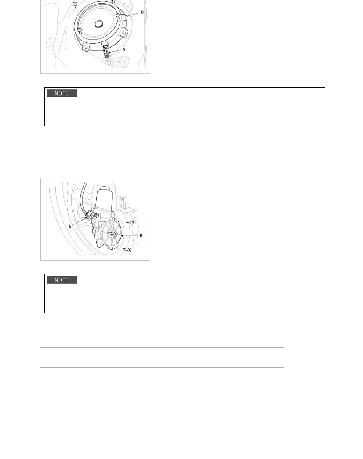
4. Installation is the reverse of removal.
• Use sheet metal screws to secure the speaker.
• Make sure the door locks/unlocks and opens/closes properly.
• Make sure the connector is connected properly.
Power Window Motor Replacement
1. Remove the door trim.
2. Remove the door screen.
3. Disconnect the connector (A)
4. After loosening the mounting screws, then remove the power window motor (B).
5. Installation is the reverse of removal.
• Grease should be applied to areas where there is rotational parts and springs.
• Roll the glass up and down to see if it move freely without binding.
• Make sure the door locks/unlocks and opens/closes properly.
Outside Handle Replacement
1. Disconnect cap, loosen the mounting bolt.
2. Remove the handle cover (A).
Tightening torque :
6.9 ~ 10.8 N.m (0.7 ~ 1.1kgf.m, 5.1 ~ 8.0 lb-ft )
Page 100
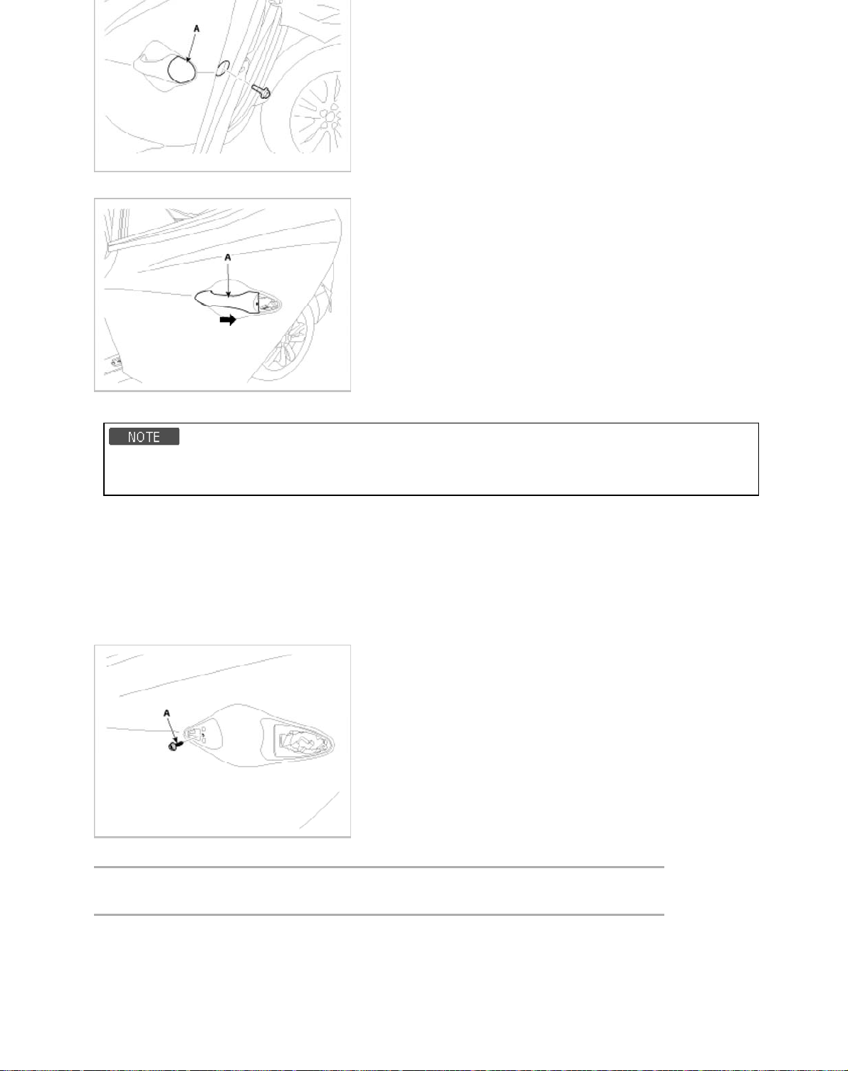
3. Remove the outside handle (A), by sliding it rearward.
2
4. Installation is the reverse of removal.
• Roll the glass up and down to see if it move freely without binding.
• Make sure the door locks/unlocks and opens/closes properly.
Door Module Assembly Replacement
1. Remove the following parts.
A. Door trim
B. Door screen
C. Window glass
D. Outside handle
2. Loosen the mounting screw (A).
3. After loosening the mounting nuts, then remove the rear channel (A).
Tightening torque :
6.9 ~ 10.8 N.m (0.7 ~ 1.1 kgf.m, 5.1 ~ 8.0 lb-ft)
 Loading...