

Hytronik Electronics HC418VRF User Manual
HYTRONIK ELECTRONICS CO.,LTD
Block A6, Nan’pu Science & Technology Park, Hao’si,
Shajing Street, Bao’an District, Shenzhen, P.R.C. 518104
T: 86 755 27322200 F: 86 755 27308687
E: info@hytronik.com W: www.hytronik.com
WORKING TEMPERATURE
PROTECTION LEVEL
STANDBY PERIOD
STANDBY DIMMING LEVEL
Detection area
Hold-time
Daylight threshold
Stand-by period
Stand-by dimming level
HC418V/RF
120~277VAC 60Hz
HC424RF
120~277VAC 60Hz
200W@120VAC; 500W@277 VAC(capatitive Load)
Up to 30 meters indoor transmission and 100
meters in open area.
Fixed address coding with 10 channels (max. 10 groups)
Diameter Max. 12m
5s~30min
Max. 6m Max. 6m
-20 ~ +60℃
-20 ~ +60℃
0s, 10s~1h, + 0s, 10s~1h, +
10~50% 10~50%
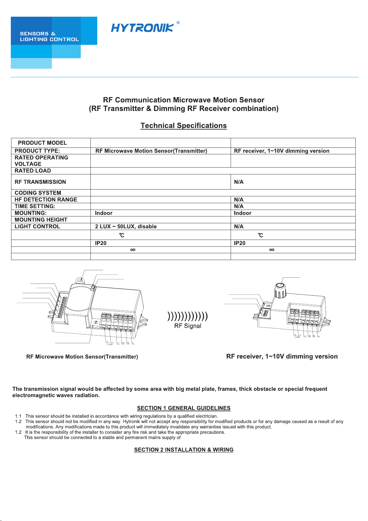
RF Antenna
LED indication
Daylight sensor
Rotary coding switch
Stand-by period
Stand-by dimming level
RF antenna
Rotary coding switch
Model NO.:HC418V/RF Model NO.:HC424RF
1.4
2.1 Ensure that the electricity supply is switched off completely before installing or servicing this product.
2.2 Keep the RF antenna at least 3cm away from the driver or ballast.
120~277VAC 60Hz.

Wring with any 1~10V control gear to achieve dimming function.
HC418V/RF
LED Driver
HC424RF
LED Driver
RF wireless communication makes installation easier with no cables connection.The motion at 1 sensor (the master unit) can
be passed onto other pre-defined individuals (the slave units) through RF transmission. This wireless radio wave transmission
can reach 100 meters in open area with internal RF antenna, 30 meters blocked by one wall, 20 meters blocked by two walls.
Settings for HC418V/RF
Detection Area:
This determines the effective range of the motion detector and is set by DIP switches at the sensor itself, refer to figure.
Note that reducing the sensitivity will also narrow the detection range.The following settings are available:
I
II
III
IV
V
VI
VII
I
II
III
IV
1 2 3
1 2
100%
75%
50%
10%
5S
30S
1min
5min
10min
20min
30min
I – maximum range up to 100%
II – 75%
III – 50%
IV – 10%
Hold time:
This determines the time the fitting remains at 100% level on motion detection and is set sith DIP swiches at the sensor
itself, refer to figure. The walk test seing is useful when installing the fitting to establish correct operation and range.
The following settings are available:
I – 5S
II – 30S
III – 1 minute
IV – 5 minutes
V – 10 minutes
VI – 20 minutes
VII – 30 minutes
Daylight sensor:
This setting holds off the 100% light output should there sufficient daylight and is set using DIP switches at the sensor, refer
to figure. The following settings are available:
I – Disable
II – 50 lux
III – 10 lux
IV – 2 lux
*In disable mode the lamp(s) will always be on with motion detected and operate at 100% light output, even in bright daylight.
II
III
IV
I
1 2
Disable
50 lux
10 lux
2 lux
Stand-by period (corridor function)
This is the time period you would like to keep at the low light output level before it is completely switched off in the long absence of people.
I – 0S
II – 10S
III – 1 minute
IV – 5 minutes
V – 10 minutes
VI – 30 minutes
VII – 1 hour
VIII – +
∞
III
IV
VI
VII
VIII
II
V
I
1 2 3
0S
10S
1min
5min
10min
30min
1h
+∞
Note: “0s” means on/off control; “+∞” means 2 steps of dimming control, fixture never switch off.
Stand-by dimming level
This is the dimmed low light output level you would like to have after the hold-time in the absence of people.
I – 10%
II – 20%
III – 30%
IV – 50%
III
IV
I
II
1 2
10%
20%
30%
50%
 Loading...