

Hytronik HED1050L + SAM7 / HIR02 Instruction Manual
INSTRUCTION MANUAL FOR 50W HEX DRIVE
MODEL NO.: HED1050L + SAM7 / HIR02
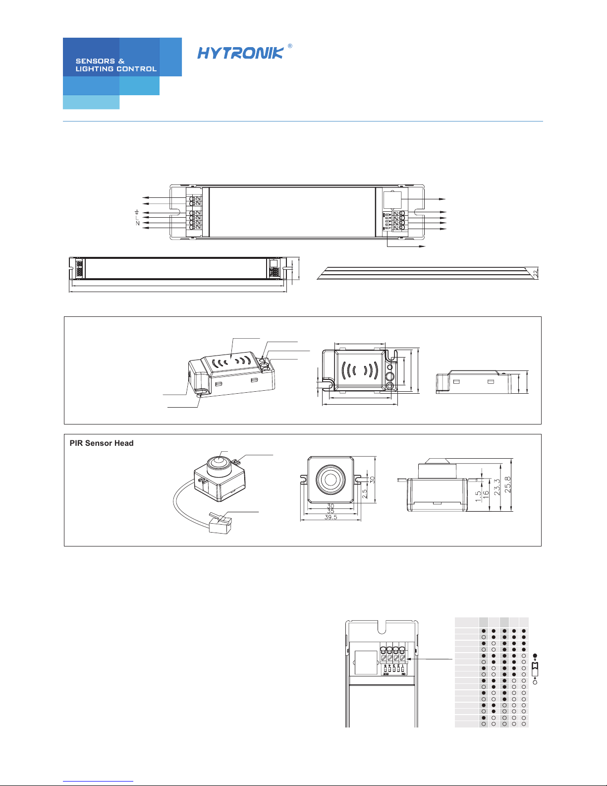
PIR Sensor Head
Model: HIR02
Lens
RJ12 connector
Installation hole
35.2
43.3
52.5
4.2
19.3
28.5
31.2
13.5
16
Detection range (DxH): 12 x 6m
Detection range (DxH): 6 x 3m
Antenna module
LED indication
Daylight sensor
Installation hole
Cable entry
Infrared remote receiver
Model: SAM7
DALI
RJ12 sensor antenna
+
1-10V
-
+
-
LED
DIP switch (for LED
current seclection)
DALI
Switch-Dim
HIGHLIGHTS
• Flicker-free dimming from 100%~30%
• In compliance with DALI 2 standard.
• DALI and switch-Dim can be used at the same time.
• Standby power < 0.5W
• Automatic output reduction 80%--60%--40%--20% against overheat
• Failure DALI feedback
LED CURRENT SELECTION
The current can be easily configured by choosing the correct
combination of the DIP switches (see table below):
mA 12345
600mA
575mA
550mA
525mA
500mA
475mA
450mA
425mA
400mA
375mA
350mA
325mA
300mA
275mA
250mA
225mA
379.5
4.5
40.5
390
HF sensor antenna
3rd Floor, block C, complex building, 155#, Bai'gang road south,
Bai'gang village, Xiao Jin Kou town, Huicheng district, Huizhou 516023
Tel:86-752-2772020 F:86-752-2777877
E: info@hytronik.com W:www.hytronik.com
CHINA FACTORY
Room D, 10/f, Tower A, Billion Center, 1 wang Kwong Road,
Kowloon Bay, Kowloon, Hongkong
T: 00852-35197525 F: 00852-30116936
E: info@hytronik.com
HYTRONIK INDUSTRIAL LIMITED
Switch-dim
2.1 Functions for driver only (without sensor head)
Synchronization
push and hold to dim
On/off control: short push (<0.4s) on the switch.
Note: Short push should be at least 0.12s, and the time interval between two pushes should be longer than 0.12s also.
Stepless dimming: long push (>0.9s) on the switch.
For fine tuning of light level: with every alternate long push, the light level goes to the opposite direction.
Built-in permanent memory: light returns to the previous dimming level when switched off and on again,
even after power failure.
Up to 64 drivers can be connected to the same switch, thanks to the programme. This means there is no need for any additional synchrony wire in
large installation, where many drivers should be controlled by one switch.
Please follow the step below to achieve synchronization function if more than one driver is connected to the same push button:
Do a long push for more than 15s, then the system is synchronized and all lights in the group dim down to 50%.
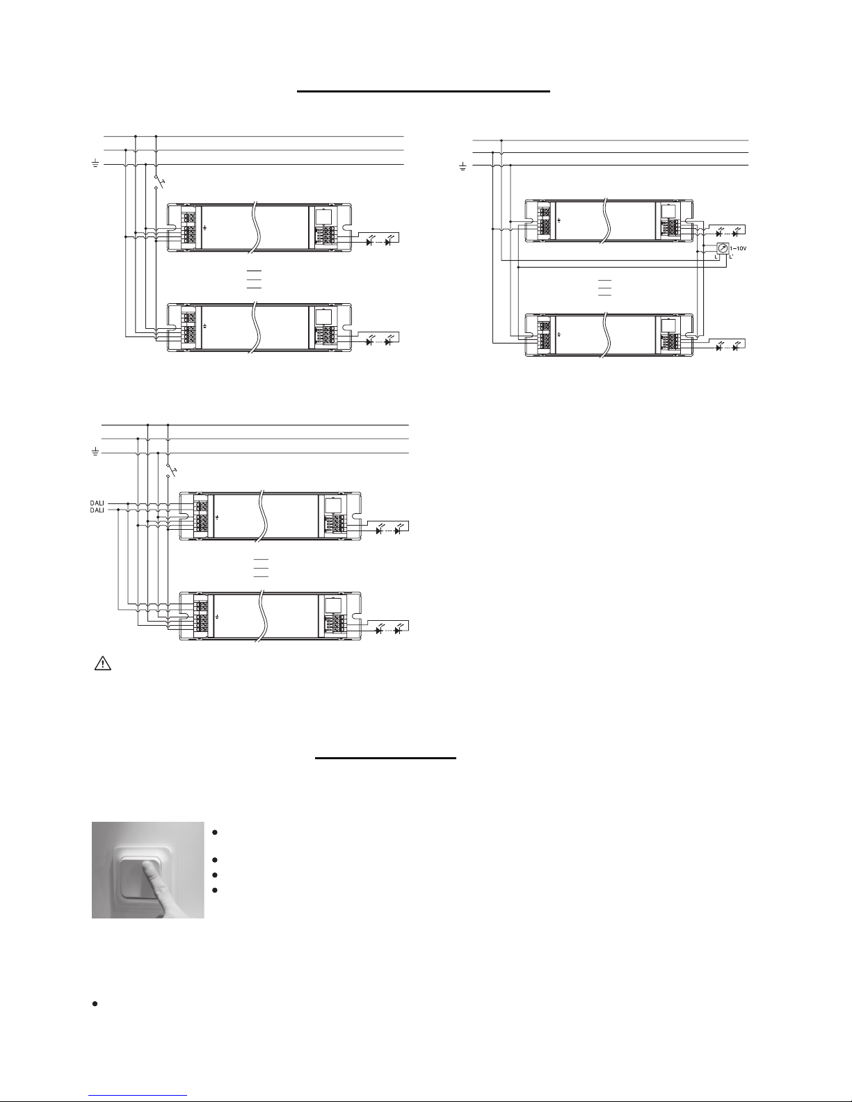
Switch-Dim Wiring Diagram
DALI + Switch-Dim Wiring Diagram
1-10V Wiring Diagram
Warning: Please make sure the correct current is selected before starting the driver!
SECTION 2 FUNCTION
SECTION 1 INSTALLATION AND WIRING
L
N
Switch-Dim
DALI
1-10V
+
-
+
-
LED
DALI
L
N
Switch-Dim
DALI
1-10V
+
-
+
-
LED
DALI
L
N
Switch-Dim
L
N
Switch-Dim
DALI
1-10V
+
-
+
-
LED
DALI
L
N
Switch-Dim
DALI
1-10V
+
-
+
-
LED
DALI
L
N
Switch-Dim
DALI
1-10V
+
-
+
-
LED
DALI
L
N
Switch-Dim
DALI
1-10V
+
-
+
-
LED
DALI
L
N
Switch-Dim
L
N
Note:1. "DALI" is prior to both "Switch-Dim" and "1-10V".
2. "Switch-Dim" is prior to "1-10V". To shift dimming from "Switch-Dim" to "1-10V", the end-user should short-circuit "1-10V" first for at least 3S.
 Loading...